Installation and operating instructions -...
64
30 61 872_0407 Subject to modifications 6 6701 623 04/07 GB Wolf GmbH · Postfach 1380 · D-84048 Mainburg · Tel. +49-8751/74-0 · Fax +49-8751/741600 · Internet: www.wolf-heiztaechnik.de die dem Menschen dient. Technik, Installation and operating instructions Programming module BM
Transcript of Installation and operating instructions -...
30 61 872_0407 1Subject to modifications 6 6701 623 04/07 GB
Wolf GmbH · Postfach 1380 · D-84048 Mainburg · Tel. +49-8751/74-0 · Fax +49-8751/741600 · Internet: www.wolf-heiztaechnik.de
die dem Menschen dient .Technik ,
Installation andoperating instructions
Programming module BM

2 30 61 872_0407
Index
Safety instructions ............................................................... 3
Standards / Regulations ...................................................... 4
Installation• Installation / Wall mounting base installation ............... 5• Electrical connection, remote control ......................... 6• Remote switching contact ........................................... 6• Outside temperature sensor ....................................... 7• Boiler integration .......................................................... 8• Integration into a gas fired boiler ................................ 9• Module installation ...................................................... 10
eBUS interface settings .................................................... 11
Overview .............................................................................. 12
Control level 1• Description l.h. / r.h. rotary selector ......................... 12• Symbol description ............................................... 12-13• Function: Flue gas test / temperature selection ....... 14• Info pushbutton .......................................................... 15• Single cylinder heating pushbutton ........................... 16• Heating pushbutton .................................................... 16• Setback pushbutton ................................................... 16• Display ................................................................... 17-18
Control level 2• Control level 2 – Summary ......................................... 19• Standard settings ...................................................... 20
- Parameters overview, standard settings .......... 20- Time ...................................................................... 20- Day ....................................................................... 21- Time program ....................................................... 21- Day temperature .................................................. 22- Setback temperature ........................................... 23- Heating curve .................................................. 24-25- Room influence .................................................... 26- S/W changeover, subject to outside temp. .... 27-28- ECO/RED ......................................................... 29-30- DHW temperature ................................................ 31- Language ............................................................. 31- Pushbutton lock ................................................... 32
• Time program (setting switching times, example) .. 33-34• Contractor
- Code scan ............................................................ 35- Overview, Contractor menu ............................... 36
• Summary – system parameters ................................ 37- Room influence (A00) ......................................... 38- Heat-up optimisation (A01) ................................. 39- Maximum heat-up time (A02) ......................... 39-40

30 61 872_0407 3
- Required heat-up time (A03) .............................. 40- Adjusted outside temperature (A04) ................. 41- Room temperature sensor matching (A05) ....... 41- External sensor (A06) ......................................... 42- Pasteurisation function (A07) ............................. 43- Maintenance message (A08) ............................. 44- Frost protection limit (A09) ................................. 44- Parallel DHW operation (A10) ............................. 45- Room temp. summer/winter changeover (A11) ... 46- Setback stop (A12) ............................................. 47- Minimum DHW temperature (A13) ...................... 48
• Summary – changing boiler parameters .............. 49-50• Summary – changing mixer parameters ................... 51• Summary – changing solar parameters ................... 52• Summary – changing other parameters ................... 53
- Screed drying, direct heating circuit ............. 54-55Reset ......................................................................... 55
Operating mode status boiler HG ................................... 56
Settings report• Standard settings parameters ............................. 56-57• Time programs ....................................................... 58-59• System parameters ................................................... 60
NTC sensor resistances ................................................... 61
Fault messages .............................................................. 62-63
Specification ......................................................................... 64
Index / Safety instructions
The following symbols are used in conjunction with theseimportant instructions concerning personal safety as well asoperational reliability.
"Safety instructions" are instructions with which you mustcomply exactly, to prevent injury and material losses.
Danger through 'live' electrical components.NB Switch OFF the ON / OFF switch before removing thecasing.
Never touch electrical components or contacts when theON / OFF switch is in the ON position. This brings a risk ofelectrocution, which may result in injury or death.
The main supply terminals are 'live' even when the ON / OFFswitch is in the OFF position.
This indicates technical instructions which you must observe toprevent material losses and boiler malfunctions.
NB
Safety instructions
4 30 61 872_0407
Standards / Regulations
- According to DIN EN 50110-1, only qualified electricians maycarry out the installation and commissioning of the heatingcontrol unit and connected accessories.
- Observe all regulations stipulated by your local power supplyutility and all VDE or local regulations.
- DIN VDE 0100 regulations regarding the installation of highvoltage systems up to 1000V
- DIN VDE 0105-100 operation of electrical systems
- DIN EN 50165 electrical equipment for non-electrical devicesfor domestic use and similar purposes
- EN 60335-1 safety equipment of electrical devices for domesticuse and similar purposes.
Installation / Commissioning
Warnings - Never remove, bypass or disable safety and monitoringequipment.
- Only operate the system in perfect technical condition.Immediately remove / remedy any faults and damage that mayimpact on safety.
- Always ensure that cold water is mixed in with hot water,when the DHW temperature is set above 60 °C or whenoperating the pasteurisation system at a temperature higherthan 60 °C (risk of scalding).
Maintenance / Repair - Regularly check the perfect function of all electrical equipment.
- Only qualified personnel may remove faults or repair damage.
- Only replace faulty components or equipment with originalWolf spare parts.
- Always maintain prescribed electrical protection values (seespecification).
Any damage or loss resulting from technical modifications toWolf control units is excluded from our liability.
NB

30 61 872_0407 5
Installation
Remote control The BM programming module can be used as remote control (e.g.in the living room). Using a remote control makes both the walkto the boiler / installation room superfluous and provides additionalfunctions (e.g. room temperature hook-up).If there are several heating circuits with controllers from the Wolfcontrol unit range, a single BM programming module canoperate and adjust all heating circuits.However, an individual BM programming module can also beallocated as remote control to each heating circuit.Only a two-wire BUS is required for the use as remote control.
Installation information - Install the wall mounting base (available as option) on aninternal wall at a height of approx. 1.5 m above the floor.
- For an optimum room temperature sensor function, install theBM programming module in a living room (reference room) thatis representative of the entire accommodation or the entirehouse.
- The BM programming module must not be subject to draughtsor direct radiated heat.
- The BM programming module must not be obstructed byfurniture or curtains.
- In the reference room, all radiator valves must be fully opened.
Wall mountingbase installation
- Remove the wall mounting base from its packing.
- Secure the wall mounting base on a flush-mounting box(Ø 55 mm) or directly on the wall.
Wall mounting base
Fixing holes Fixing holes

6 30 61 872_0407
Installation
All accessories are connected in parallel to the control unit eBUSwhen connecting several remote control units or a radio clockmodule.
Note
- Click the BM programming module into the wall mounting baseas shown in the diagram.
- Switch ON the ON / OFF switch at the boiler.
Remote switchingcontact
A remote switching contact offers the possibility of switchingthe heating system to enable 24 h central heating and DHW, usinga zero-volt contact (e.g. a telecontrol contact). The control unitoperates with the set time programs if the remote switchingcontact remains open.
- Switch OFF the ON / OFF switch at the boiler.- Wire the remote switching contact with a 2-core cable (minimum
cross-section 0.5 mm²) in accordance with the diagram.
21 gr
ün
Terminal stripWall mounting base
Green plug ofthe control unit
eBUS
Remote switching contact (on site)e.g. telecontrol contact
Electrical connectionRemote control
The electrical connection must only be carried out by a qualifiedelectrician.
Never route sensor leads alongside mains power cables.
- Switch OFF the ON / OFF switch at the boiler.- Set the rotary temperature selector for central heating and the
DHW selector into their central positions (5).- Wire the wall mounting base with a two-core cable (minimum
cross-section 0.5 mm²) in accordance with the diagram.
21 gr
üneBUS
- Connect the optional outside temperature sensor to the wallmounting base.
- Connect the remote switching contact to the wall mounting base.- Check the eBUS address (see chapter "eBUS interface settings").- Click the BM programming module into the wall mounting base as
shown in the diagram.- Switch ON the ON / OFF switch at the boiler.
Green plug ofthe control unit
Terminal stripWall mounting base
gre
eng
reen

30 61 872_0407 7
Installation
Outside temperaturesensor
Installation at the boiler
The outside temperature sensor can either be connected directlyto the boiler (preferred option) or at the BM programming module.Join the on-site lead of the outside temperature sensor with theplug supplied in the boiler control unit. Insert the plug into thedesignated location in the plug-in connector strip of the boilercontrol unit, and secure the lead with its strain relief. Route thelead through the boiler casing cutout. Fit the outside temperaturesensor to the north or northeast wall, 2 to 2.5 m above groundlevel (cable entry pointing down).
A wireless outside temperature sensor can also be used if thereis no cable or conduit available on site for the outside temperaturesensor.
A wireless outside temperature sensor or a radio clock modulewith outside temperature sensor is available as optionalaccessory.
External wireless sensor
eBUS21
2
ϑ
Radio clock module withoutside temperature sensor
eBUS2
21
ϑ
Outside temperature sensor
OS at theboiler
2
ϑ
21 gr
ün
ϑ
- Click the BM programming module into the wall mounting baseas shown in the diagram.
- Switch ON the ON / OFF switch at the boiler.
Terminal stripWall mounting base
Green plug ofthe control unit
eBUS
Outside temp. sensor
Installation at theprogramming module
- Switch OFF the system ON / OFF switch at the boiler controlunit.
- Wire the outside temperature sensor with a 2-core lead (minimumcross-section 0.5 mm²) in accordance with the diagram.
gre
en

8 30 61 872_0407
Installation
The BM programming module can also be integrated into the boilercontrol unit. That means that all settings are made at the boilercontrol unit.In addition, all heating circuits can be controlled and adjustedfrom the boiler control unit, if there are several heating circuitsthat are operated with components from the Wolf range ofcontrol equipment.
The electrical connection must only be carried out by a qualifiedelectrician.
- Switch OFF the ON / OFF switch at the boiler.- Set the rotary temperature selector for central heating and the
DHW selector into their central positions (5).- Check the eBUS address (see chapter "eBUS interface
settings").- Remove the facia or the BM programming module from the
boiler control unit as shown in the diagram.- Click the BM programming module or facia into the boiler control
unit as shown in the diagram.- Switch ON the ON / OFF switch at the boiler.
Boiler integration

30 61 872_0407 9
Installation
The BM programming module can also be integrated into thecontrol unit of gas fired boilers. That means that all settings aremade at the control unit of the gas fired boiler.In addition, all heating circuits can be controlled and adjustedfrom the control unit of the gas fired boiler, if there are severalheating circuits that are operated with components from the Wolfrange of control equipment.
The electrical connection must only be carried out by a qualifiedelectrician.
- Switch OFF the ON / OFF switch at the boiler.- Set the rotary temperature selector for central heating and the
DHW selector into their central positions (5). Check the eBUSaddress (see chapter "eBUS interface settings").
- Remove the facia from the control unit of the gas fired boileras shown in the diagram.
- Click the BM programming module into the control unit of the gasfired boiler as shown in the diagram.
- Switch ON the ON / OFF switch at the boiler.
Integration into a gasfired boiler

10 30 61 872_0407
Installation
The BM programming module can also be integrated into modules(e.g. mixer module MM, solar module SM). That means that allsettings are made at the relevant module.
The electrical connection must only be carried out by a qualifiedelectrician.
- Switch OFF the ON / OFF switch (or system ON / OFF switch)at the module.
- Remove the facia from the module as shown in the diagram.- Check the eBUS address of the BM programming module and
the module (see chapter "eBUS interface settings").- Click the BM programming module into the module as shown
in the diagram.- Switch ON the ON / OFF switch (or system ON / OFF switch)
at the module.
Module installation

30 61 872_0407 1 1
eBUS interface settings
The BM programming module is factory-set so that all connectedcomponents of the heating system are controlled from theprogramming module. You can ignore the following chapter, ifonly one BM programming module is to be installed as part of theheating system.
In addition, the programming module can be used to provide thecomplete control of an extension module (see the illustrationbelow as example).For this, set the DIP switch at the back of the programming moduleinto the correct position (see illustration).
Note:One BM with address 0 must always be part of the system.Up to seven extension modules can be connected.
SettingeBUS interface
1 2 3 4
Dip 1-4
ON
OFF
ON DIP
(Werkseinstellung)
Adresse 2 Adresse 3 Adresse 4 Adresse 5 Adresse 6 Adresse 7
Einstellung eBUS
Adresse 0 Adresse 1
A correct BUS address and consequently the communication ofall users with each other is indicated in the display of theconnected BM programming module after approx. one minute bysymbol (see diagram) or by an LED in the expansion modules.
eBUS connectionenabled
Address 0 (factory settings)Address 1
Address 2
Address 3
Address 4
Address 5
Address 6Address 7
Setting eBUS
12 30 61 872_0407
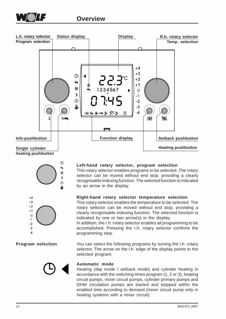
Automatic modeHeating (day mode / setback mode) and cylinder heating inaccordance with the switching times program (1, 2 or 3), heatingcircuit pumps, mixer circuit pumps, cylinder primary pumps andDHW circulation pumps are started and stopped within theenabled time according to demand (mixer circuit pump only inheating systems with a mixer circuit).
Program selection You can select the following programs by turning the l.h. rotaryselector. The arrow on the l.h. edge of the display points to theselected program.
Overview
L.h. rotary selectorProgram selection
R.h. rotary selectorTemp. selection
Info pushbutton
Single cylinderheating pushbutton
Heating pushbutton
Right-hand rotary selector temperature selectionThis rotary selector enables the temperature to be selected. Therotary selector can be moved without end stop, providing aclearly recognisable indexing function. The selected function isindicated by one or two arrow(s) in the display.In addition, the r.h. rotary selector enables all programming to beaccomplished. Pressing the r.h. rotary selector confirms theprogramming step.
Left-hand rotary selector, program selectionThis rotary selector enables programs to be selected. The rotaryselector can be moved without end stop, providing a clearlyrecognisable indexing function. The selected function is indicatedby an arrow in the display.
Function display
DisplayStatus display
Setback pushbutton

30 61 872_0407 1 3
Control level 1
Summer mode (heating OFF)Summer mode (heating OFF) means only cylinder heating inaccordance with the switching times program. Frost protectionfor the central heating system and anti-seizing pump protectionare enabled.
Constant DHW and central heating operationThe switching times program (1, 2 or 3) for heating and cylinderheating are disabled. With this setting, the day mode for centralheating and cylinder heating are enabled for 24 hours. The heatingcircuit pump, mixer circuit pump and cylinder primary pump arestarted and stopped according to demand. The DHW circulationpump is started and stopped in accordance with the switching timesprogram (mixer circuit pump only for heating systems with mixercircuit). No summer/winter changeover.
Constant setback modeThe switching times program (1, 2 or 3) for heating is disabled. Withthis setting, the heating operates in setback mode for 20 hours. Theheating circuit and mixer circuit pumps are started and stoppedaccording to demand.The cylinder primary pump and the DHW circulation pumps are startedand stopped in accordance with the switching times program (1, 2or 3) (mixer circuit pump only for heating systems with mixer circuit).Summer/winter changeover and ECO/RED are enabled.
Standby modeBurner and circulation pumps are OFF, cylinder heating andpasteurisation are OFF, frost protection and anti-seizing pumpprotection are enabled.Frost protection:At outside temperatures below the set value (factory setting +2 °C),the boiler and mixer circuit pumps (mixer circuit pump only in heatingsystems with mixer circuit) run permanently, the mixers open.Anti-seizing pump protection:After no more than 24 hours idle, the pumps will run for approx. 20seconds. This prevents the pumps from seizing up.
Flue gas testThe flue gas test is required by your flue gas inspector or aspecialist contractor for measuring the emissions.
- This selection is not available if the BM programming moduleis installed as remote control (e.g. in a living room). In that case,the emissions test mode is activated at the boiler control unitvia the heating water temperature selector and is indicated bythe signal ring flashing in yellow.
- If the BM programming module is integrated into the boilercontrol unit, activating the emissions test mode is thenindicated by an arrow in the display (next to the chimneysweep symbol) as well as by the signal ring flashing in yellow.
For the flue gas test function, see the next page.

14 30 61 872_0407
Temperature selectionBy turning the r.h. rotary selector, the required room temperaturecan be raised or lowered by a maximum of 4 K by turning theselector respectively anti-clockwise or clockwise. Subject tothe direction of rotation, the arrow on the r.h. side of the displaydrifts either up or down.
Example:+1: The set room temperature is raised by approx. 1 K.- 1: The set room temperature is reduced by approx. 1 K.
If two arrows are displayed one above the other, the selectedvalue will be between both.
Example:Arrow 1 +1, arrow 2 +2: The set room temperature is raised byapprox. 1.5 K.
0 corresponds to the selected room temperature (factory setting:day mode 20 °C, setback mode 12 °C).
The current room temperature will not be captured, if the BMprogramming module is integrated into the boiler control unit orif it is operated as remote control with room influence switchedOFF. The selected room temperatures are simply reference andcalculating values for the heating curve; therefore the actualroom temperature can deviate from these values.
Control level 1
Freestanding boilers:The heating system will not operate in weather-compensatedmode, when the emission test is running. Instead it operatesat maximum output and tries to hold a mean constant boilerwater temperature of 60 °C. Only the burner will operate, i.e.the pump is OFF, if the boiler water temperature is lower than60 °C. The boiler circuit pump will be started when the boilerwater temperature exceeds 60 °C. The DHW cylinder primarypump only runs until the set DHW temperature has beenreached. The burner is switched OFF when the max. boilerwater temperature has been reached, if the heating energysupplied cannot be transferred.
Wall mounted boilers:In emissions test mode, the heating system will not operate inweather-compensated mode, but with maximum output. Anyprevious cycle block will be cancelled. The heating circuitpump runs permanently.
The emissions test mode terminates either after 15 minutes orautomatically, if the maximum flow temperature has beenexceeded. For a repeat activation, turn the heating watertemperature selector or the l.h. rotary selector (programselector) first anti-clockwise and then back into position .
Function: Flue gas test

30 61 872_0407 1 5
Control level 1
Info pushbuttonAll available set and actual temperatures, burner starts andhours run as well as other system values can be displayed withthe Info pushbutton.Pressing the Info pushbutton several times displays the followingvalues in sequence, subject to the relevant sensor beingconnected. Any circuits that are not connected are skipped, asonly available values can be displayed.The relevant parameters are displayed if additional programmingmodules BM are integrated into the Wolf control system or areinstalled as remote control units.
Display NameDHW TEMP Actual DHW cylinder temp., heating (°C)
Set DHW temp., heating (°C)Solar dhw 1 Actual DHW temp., solar heating system (°C)dhw SOL 24H Max. temp., solar cylinder sensor (°C)
Min. temp., solar cylinder sensor (°C)Collector 1 Collector temp., solar heating system (°C)Collect 24H Max. temp., collector, solar heating system (°C)
Min. collector temp., solar heating system (°C)Return Return temp., solar heating system (°C)Flow rate Throughput of the solar circuit (l / min)opERATION H Hours run, solar circuit pump (h) **Sol. output Current output, solar heating system (kW)OUTPUT 24 H Current yield, day, solar heating system (kWh) **OUTPUT KWH Total yield, solar heating system (kWh) **OUTPUT MWH Total yield, solar heating system (MWh) **SOL STATUS DHW heating, solar heating system
Pasteurisation(0 = not successful / 1 = successful)
OUT TEMP Outside temperature (°C)ES AVERAGE Average outside temp. (°C)ES MAX MIN Max. outside temp. (°C, 0 to 24 h)
Min. outside temp. (°C, 0 to 24 h)ROOM TEMP Actual room temp. (°C)
Set room temp. (°C)MODE HC Operating mode, heating circ. (sun, moon, standby)BOILER TEMP Actual boiler water temp. (°C)
Set boiler water temp. (°C)MIX VALVE 1 Actual mixer temp. (°C)(mixer 2-7) Set mixer temp. (°C)
Mixer circuit operating mode (sun, moon, standby)RETURN Actual return temp. (°C)STATUS HG Boiler statusBURN RUN H Burner hours runBURN START Boiler burner starts
Example:
* No values are displayed for modules that are not connected(mixer module MM, solar module SM).
** This value can be reset to 0 by holding down the rotaryselector for at least 10 seconds.
**
**
********
*
dhw TEMP

16 30 61 872_0407
Control level 1
Setback pushbuttonTo avoid the need for changing the switching times programduring absence or holidays, the setback temperature can beselected by pressing the Setback pushbutton, independent ofthe Switching times program or the program selection.After pressing the Setback pushbutton, setback mode will bedisplayed automatically for three hours. Pressing the r.h. rotaryselector enables the selection of the required time in hours ordays (up to 30 days).Pressing the r.h. rotary selector enables the Setback function.To signal this event, the moon symbol or Standby (ECO/REDfunction) flashes in the display during the unscheduled setback.This function is stopped automatically after the set time hasexpired (hours or days).Pressing the Setback pushbutton again terminates this functionearly.
Heating pushbuttonTo avoid the need for changing the switching times programduring bank holidays, parties or illness, the day temperature canbe selected by pressing the Heating pushbutton, independent ofthe Switching times program or the program selection.After pressing the Heating pushbutton, heating mode will bedisplayed automatically for three hours. Pressing the r.h. rotaryselector enables the selection of the required time in hours ordays (up to 30 days).Pressing the r.h. rotary selector enables the Heating function.To signal this event, the sun symbol flashes in the display duringthe unscheduled heating operation.This function is stopped automatically after the set time hasexpired (hours or days).Pressing the Heating pushbutton again terminates this functionearly.
Single cylinder heating pushbuttonPressing the single cylinder heating pushbutton enables anunscheduled single cylinder heating, if DHW is required outsidethe selected DHW switching times. To signal this event, the tapsymbol flashes in the display during the unscheduled cylinderheating. The single cylinder heating terminates automaticallyafter one hour, and the control unit continues to operate inaccordance with the current switching times program.Pressing the single cylinder heating pushbutton again terminatesthis function early.
30 61 872_0407 1 7
Display
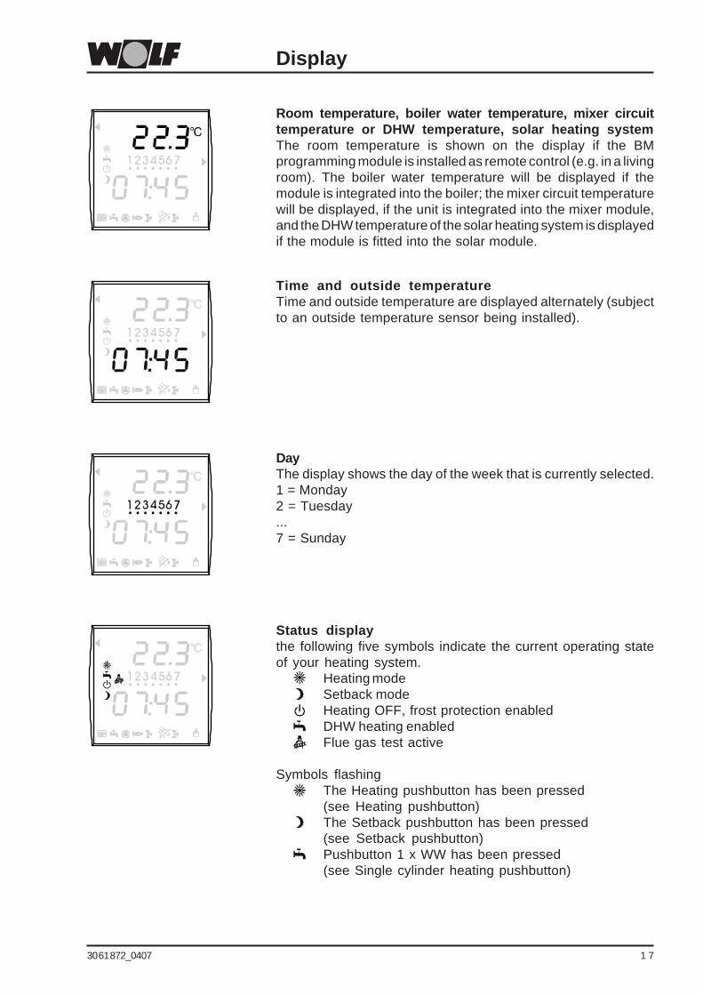
Room temperature, boiler water temperature, mixer circuittemperature or DHW temperature, solar heating systemThe room temperature is shown on the display if the BMprogramming module is installed as remote control (e.g. in a livingroom). The boiler water temperature will be displayed if themodule is integrated into the boiler; the mixer circuit temperaturewill be displayed, if the unit is integrated into the mixer module,and the DHW temperature of the solar heating system is displayedif the module is fitted into the solar module.
Time and outside temperatureTime and outside temperature are displayed alternately (subjectto an outside temperature sensor being installed).
DayThe display shows the day of the week that is currently selected.1 = Monday2 = Tuesday...7 = Sunday
Status displaythe following five symbols indicate the current operating stateof your heating system.
Heating modeSetback modeHeating OFF, frost protection enabledDHW heating enabledFlue gas test active
Symbols flashingThe Heating pushbutton has been pressed(see Heating pushbutton)The Setback pushbutton has been pressed(see Setback pushbutton)Pushbutton 1 x WW has been pressed(see Single cylinder heating pushbutton)

18 30 61 872_0407
Display
Submenu available
Right hand arrowselected temperature
Left hand arrowselected heating program
Function displays:
Boiler in heating mode
Boiler in DHW mode
Boiler pump ON
Burner ON
Mixer circuit pump mixer 1 ON
Mixer circuit pump mixer 2 ON
Programmable output ON
BUS connection enabled
Solar circuit pump enabled
DISPLAY
30 61 872_0407 1 9
Control level 2 – Summary
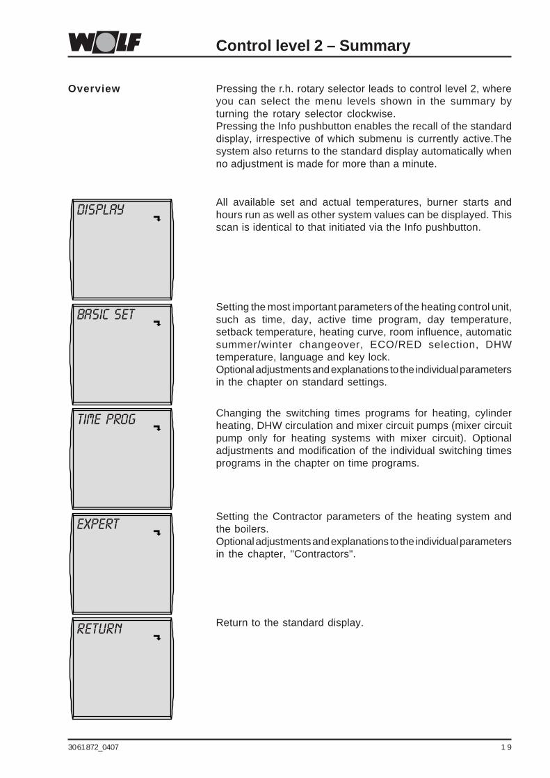
BASIC SETSetting the most important parameters of the heating control unit,such as time, day, active time program, day temperature,setback temperature, heating curve, room influence, automaticsummer/winter changeover, ECO/RED selection, DHWtemperature, language and key lock.Optional adjustments and explanations to the individual parametersin the chapter on standard settings.
Time prog Changing the switching times programs for heating, cylinderheating, DHW circulation and mixer circuit pumps (mixer circuitpump only for heating systems with mixer circuit). Optionaladjustments and modification of the individual switching timesprograms in the chapter on time programs.
RETURN Return to the standard display.
EXPERTSetting the Contractor parameters of the heating system andthe boilers.Optional adjustments and explanations to the individual parametersin the chapter, "Contractors".
Pressing the r.h. rotary selector leads to control level 2, whereyou can select the menu levels shown in the summary byturning the rotary selector clockwise.Pressing the Info pushbutton enables the recall of the standarddisplay, irrespective of which submenu is currently active.Thesystem also returns to the standard display automatically whenno adjustment is made for more than a minute.
Overview
DisplayAll available set and actual temperatures, burner starts andhours run as well as other system values can be displayed. Thisscan is identical to that initiated via the Info pushbutton.

20 30 61 872_0407
Parameter Setting range Factory settingTime 0 to 24 h -Day 1 (Mon) to 7 (Sun) -Time program 1 / 2 / 3 1Day temp. 5 to 30 °C 20 °CSetback temp. 5 to 30 °C 16 °CHeating curve Boiler circuit 0 to 3.0 1.2
Mixer circuit 0 to 3.0 0.8Room influence ON / OFF OFFSummer/winter changeover 0 to 40 °C 20 °CECO/RED -10 to 40 °C 10 °CDHW temp. Freestanding boiler 15 to 60 °C 55 °C
Wall mounted boiler with cylinder 15 to 65 °C 55 °CWall mounted combi boiler 40 to 65 °C 55 °C
Language German, English, GermanFrench, Dutch,
Spanish,Portuguese,
Italian, Czech,Polish, Slovakian,
Hungarian,Russian,
Greek, TurkishPushbutton lock ON / OFF OFF
Parameter overview, standard settings(Settings and functions on the following pages)
Control level 2 – Standard settings
Time
08:30
Press the r.h. rotary selector to change to control level 2. Turnthe r.h. rotary selector clockwise to select the Standard settingssubmenu and confirm the selection by pressing the r.h. rotaryselector again.
The time is changed by pressing (display indication flashes)and then turning the r.h. rotary selector.
Turning slowly = Changing the minutesTurning quickly = Changing the hour
After setting or changing the current time, pressing the r.h.rotary selector again confirms the input.
Pressing the Info pushbutton returns the standarddisplay.
There will be no automatic change between summer and wintertime. Reset the time if the control unit has been disconnected fromthe power supply longer than 48 hours.The time will be displayed automatically if a radio clock moduleis connected. However, the time cannot then be changed.
Time
Setting range: 0 to 24 h

30 61 872_0407 2 1
Control level 2 – Standard settings
Press the r.h. rotary selector to change to control level 2. Turnthe r.h. rotary selector clockwise to select the Standard settingssubmenu and confirm the selection by pressing the r.h. rotaryselector again. Select the Time program parameter by turningthe rotary selector further clockwise.
The time program 1, 2 or 3 is selected by pressing (displayindication flashes) and then turning the r.h. rotary selector.After selecting the time program, pressing the r.h. rotary selectoragain confirms the input.
Pressing the Info pushbutton returns the standarddisplay.
Please note:You can match the switching times to individual requirements.For setting options and explanations to the programming ofswitching times, see the chapter on switching times programming.
Time program
Factory setting: 1Setting range: 1 / 2 / 3
Individual settings: _______
Time prog
1
Day
08:30
Press the r.h. rotary selector to change to control level 2. Turnthe r.h. rotary selector clockwise to select the Standard settingssubmenu and confirm the selection by pressing the r.h. rotaryselector again. Select the Day parameter by turning the rotaryselector further clockwise.
The day is changed by pressing (display indication flashes)and then turning the r.h. rotary selector. After setting or changingthe current day (1 = Monday .... 7 = Sunday), pressing the r.h.rotary selector again confirms the input.
Pressing the Info pushbutton returns the standarddisplay.
Reset the day if the control unit has been disconnected from thepower supply longer than 48 hours. The time will be displayedautomatically if a radio clock module is connected. However, thetime cannot then be changed.
Day
Setting range: 1 (Mon) to 7 (Sun)

22 30 61 872_0407
Control level 2 – Standard settings
If several heating circuits are connected, that heating circuit isselected at this point the settings of which are to be changed.
If settings are made for the mixer circuits (day temperature,setback temperature, heating curve, room influence, SU / WIchangeover, ECO/RED) at the programming module, call up therespective value from the mixer module. It may, therefore, takeseveral seconds before the value can be changed.
Info
TEMP DAY
20.0 °C
Press the r.h. rotary selector to change to control level 2. Turnthe r.h. rotary selector clockwise to select the Standard settingssubmenu and confirm the selection by pressing the r.h. rotaryselector again. Select the Day temperature parameter by turningthe rotary selector further clockwise.
Note:If more than one heating circuit is present in the heating system(mixer circuit 1 up to mixer circuit 7), select heating circuit (HK)or mixer circuit 1 ...7 (mixer 1...7) by turning the r.h. rotary selectoragain clockwise at the standard settings menu level, and confirmthe selection by pressing the r.h. rotary selector. Select the Daytemperature parameter by turning the rotary selector furtherclockwise.
The day temperature is changed by pressing (display indicationflashes) and then turning the r.h. rotary selector. After selectingthe day program, pressing the r.h. rotary selector again confirmsthe setting.
Pressing the Info pushbutton returns the standarddisplay.
Please note:A different day temperature can be selected for each of theheating circuits remotely controlled by this programming module.
For control units that are purely room temperature-dependent(Room influence OFF parameter or programming module onlyintegrated into the boiler control unit), the selected day temperatureis only an approximation and serves as calculation value for theheating curve.
Day temperature(set room temperature,heating mode)
Factory setting: 20 °CSetting range: 5 to 30 °C
Individual settings:
Heating circuit: ____________
Mixer circuit 1: ____________
Mixer circuit 2: ____________
Mixer circuit 3: ____________
Mixer circuit 4: ____________
Mixer circuit 5: ____________
Mixer circuit 6: ____________
Mixer circuit 7: ____________
30 61 872_0407 2 3
Control level 2 – Standard settings
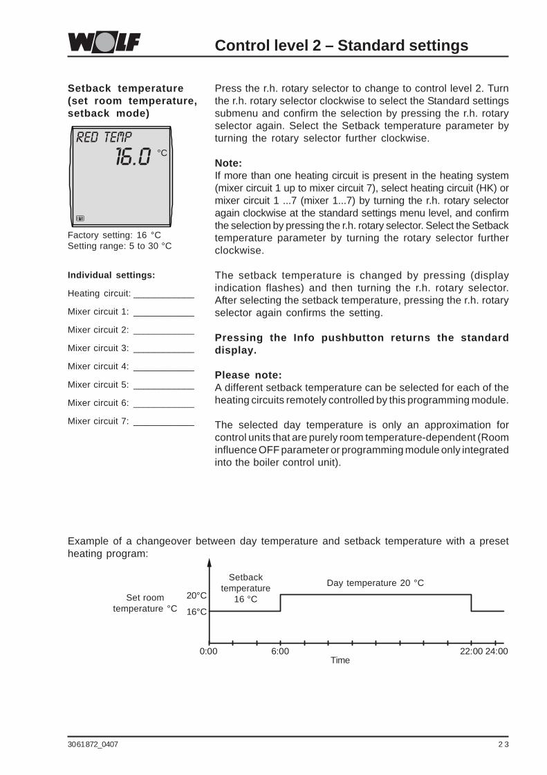
RED TEMP
16.0 °C
Press the r.h. rotary selector to change to control level 2. Turnthe r.h. rotary selector clockwise to select the Standard settingssubmenu and confirm the selection by pressing the r.h. rotaryselector again. Select the Setback temperature parameter byturning the rotary selector further clockwise.
Note:If more than one heating circuit is present in the heating system(mixer circuit 1 up to mixer circuit 7), select heating circuit (HK) ormixer circuit 1 ...7 (mixer 1...7) by turning the r.h. rotary selectoragain clockwise at the standard settings menu level, and confirmthe selection by pressing the r.h. rotary selector. Select the Setbacktemperature parameter by turning the rotary selector furtherclockwise.
The setback temperature is changed by pressing (displayindication flashes) and then turning the r.h. rotary selector.After selecting the setback temperature, pressing the r.h. rotaryselector again confirms the setting.
Pressing the Info pushbutton returns the standarddisplay.
Please note:A different setback temperature can be selected for each of theheating circuits remotely controlled by this programming module.
The selected day temperature is only an approximation forcontrol units that are purely room temperature-dependent (Roominfluence OFF parameter or programming module only integratedinto the boiler control unit).
Setback temperature(set room temperature,setback mode)
Factory setting: 16 °CSetting range: 5 to 30 °C
Individual settings:
Heating circuit: ____________
Mixer circuit 1: ____________
Mixer circuit 2: ____________
Mixer circuit 3: ____________
Mixer circuit 4: ____________
Mixer circuit 5: ____________
Mixer circuit 6: ____________
Mixer circuit 7: ____________
Example of a changeover between day temperature and setback temperature with a presetheating program:
Day temperature 20 °CSetback
temperature16 °C
Time
Set roomtemperature °C
0:00
16°C
20°C
6:00 22:00 24:00

24 30 61 872_0407
Control level 2 – Standard settings
GRADIENT
1.2
The Heating curve parameter will not be displayed whenthe system is regulated only in room temperature-dependent mode.
Press the r.h. rotary selector to change to control level 2. Turnthe r.h. rotary selector clockwise to select the Standard settingssubmenu and confirm the selection by pressing the r.h. rotaryselector again. Select the Heating curve parameter by turningthe rotary selector further clockwise.
Note:If more than one heating circuit is present in the heating system(mixer circuit 1 up to mixer circuit 7), select heating circuit (HK) ormixer circuit 1 ...7 (mixer 1...7) by turning the r.h. rotary selectoragain clockwise at the standard settings menu level, and confirmthe selection by pressing the r.h. rotary selector.Select the Heating curve parameter by turning the rotary selectorfurther clockwise.
The Heating curve parameter is set by pressing (displayindication flashes) and then turning the r.h. rotary selector.After changing the Heating curve parameter, pressing the r.h.rotary selector again confirms the setting.
Pressing the Info pushbutton returns the standarddisplay.
Please note:A different heating curve can be selected for each of the heatingcircuits remotely controlled by this programming module.
Heating curve
Factory setting:Boiler circuit: 1.2Mixer circuit: 0.8
Setting range: 0 to 3.0
Individual settings:
Heating circuit: ____________
Mixer circuit 1: ____________
Mixer circuit 2: ____________
Mixer circuit 3: ____________
Mixer circuit 4: ____________
Mixer circuit 5: ____________
Mixer circuit 6: ____________
Mixer circuit 7: ____________
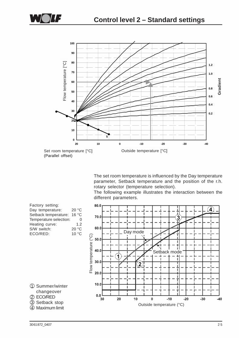
This setting will be made by the heating contractor for each heatingcircuit separately, subject to the heating system, the thermalinsulation of the building and the relevant climatic zone.Setting the slope will match the heating water temperature tothese conditions.The following diagram indicates an example applicable to thefollowing heating system:- Climate zone with an average minimum outside temperature of -14 °C- Radiator for flow/return temperatures 60/50 °C, with direct control- Thermal building insulation in accordance with current regulationsFor all other conditions, match the slope to the prevailingcircumstances. The slope must always be set so that, at the min.outside temperature, the maximum flow temperature for the radiatorsor the underfloor heating system will be achieved.As rule of thumb, a slope of 1.0 can be used for a radiator heatingsystem, and a slope of 0.4 for underfloor heating systems in awell insulated house. Similarly, a slope of 1.4 can be used for aradiator heating system, and a slope of 0.8 for underfloor heatingsystems in a less well insulated house.
Function explainedHeating curve
30 61 872_0407 2 5
Control level 2 – Standard settings
Outside temperature [°C]
Gra
die
nt
Set room temperature [°C](Parallel offset)
0
10
20
30
40
50
60
70
80
90
100
-40-30-20-1001020
Aussentemperatur [°C]
Vo
rlau
ftem
per
atu
r
5
0.2
0.4
0.6
0.8
1.0
1.2F
low
tem
pera
ture
[°C
]
The set room temperature is influenced by the Day temperatureparameter, Setback temperature and the position of the r.h.rotary selector (temperature selection).The following example illustrates the interaction between thedifferent parameters.
Flo
w te
mpe
ratu
re (
°C)
Outside temperature (°C)
1 Summer/winterchangeover
2 ECO/RED3 Setback stop4 Maximum limit
Factory setting:Day temperature: 20 °CSetback temperature: 16 °CTemperature selection: 0Heating curve: 1.2S/W switch: 20 °CECO/RED: 10 °C
Setback mode
Day mode

26 30 61 872_0407
Control level 2 – Standard settings
ROOM INFLu
OFF
Room influence
Factory setting: OFFSetting range: ON / OFF
Individual settings:
Heating circuit: ____________
Mixer circuit 1: ____________
Mixer circuit 2: ____________
Mixer circuit 3: ____________
Mixer circuit 4: ____________
Mixer circuit 5: ____________
Mixer circuit 6: ____________
Mixer circuit 7: ____________
The Room influence parameter will not be displayed ifthe BM programming module is integrated into theboiler control unit.Press the r.h. rotary selector to change to control level 2. Turnthe r.h. rotary selector clockwise to select the Standard settingssubmenu and confirm the selection by pressing the r.h. rotaryselector again. Select the Room influence parameter by turningthe rotary selector further clockwise.
Note:If more than one heating circuit is present in the heating system(mixer circuit 1 up to mixer circuit 7), select heating circuit (HK)or mixer circuit 1 ...7 (mixer 1...7) by turning the r.h. rotaryselector again clockwise at the standard settings menu level,and confirm the selection by pressing the r.h. rotary selector.Select the Room influence parameter by turning the rotaryselector further clockwise.
The Room influence parameter is set by pressing (displayindication flashes) and then turning the r.h. rotary selector.After changing the Room influence parameter, pressing the r.h.rotary selector again confirms the setting.
Pressing the Info pushbutton returns the standarddisplay.
Please note:A Room influence can be switched ON or OFF for each of theheating circuits remotely controlled by this programming module.
Function explainedRoom influence
Using room influence, room temperature fluctuations due toexternal heat or cold (e.g. solar irradiation, woodburning stoveor open windows) can be compensated. Room influence willonly work if the BM programming module is operated as remotecontrol. A room temperature sensor is integrated into theprogramming module that captures the actual room temperatureand compares it with the set value (day or setback temperature).Activating room influence results in a correction of the weather-compensated calculated flow temperature via a room temperaturesensor, either upwards (actual room temperature lower than theset room temperature) or downwards (actual room temperaturehigher than the set room temperature). The level of temperaturecorrection can be set via system parameter A00 (see the"Contractor" chapter).

30 61 872_0407 2 7
Control level 2 – Standard settings
W/S SWITCH
20.0 °C
The summer/winter changeover parameter will not bedisplayed when the system is regulated only in roomtemperature-dependent mode (no outside temperaturesensor).
Press the r.h. rotary selector to change to control level 2. Turnthe r.h. rotary selector clockwise to select the Standard settingssubmenu and confirm the selection by pressing the r.h. rotaryselector again. Select the summer/winter changeover parameterby continuing to turn the selector clockwise.
Note:If more than one heating circuit is present in the heating system(mixer circuit 1 up to mixer circuit 7), select heating circuit (HK)or mixer circuit 1 ...7 (mixer 1...7) by turning the r.h. rotaryselector again clockwise at the standard settings menu level,and confirm the selection by pressing the r.h. rotary selector.Select the summer/winter changeover parameter by continuingto turn the selector clockwise.
The summer/winter changeover parameter is set by pressing(display indication flashes) and then turning the r.h. rotaryselector. After changing the summer/winter changeoverparameter, pressing the r.h. rotary selector again confirms thesetting.
Pressing the Info pushbutton returns the standarddisplay.
Please note:A different summer/winter changeover can be selected foreach of the heating circuits remotely controlled by thisprogramming module.
Summer/winterchangeover, subject tooutside temperature
Factory setting: 20 °CSetting range: 0 to 40 °C
Individual settings:
Heating circuit: ____________
Mixer circuit 1: ____________
Mixer circuit 2: ____________
Mixer circuit 3: ____________
Mixer circuit 4: ____________
Mixer circuit 5: ____________
Mixer circuit 6: ____________
Mixer circuit 7: ____________

28 30 61 872_0407
The control unit constantly calculates an average outsidetemperature over several hours, i.e. during day and nightoperation (setback mode).
- The heating system will be immediately switched OFF, if theadjusted outside temperature exceeds the preselected setvalue.
- The heating system will be automatically switched ON, if theadjusted average temperature falls more than 2 K below thepreselected set value.
The DHW cylinder heating continues in accordance with theselected switching times program.
Example 1:Temperature setting 20 °C.Time setting: 3 hAverage temperature over the last 3 h = 21 °C.The heating system remains OFF (pumps OFF, mixer closed).
Example 2:Temperature setting 20 °C.Time setting: 3 hAverage temperature over the last 3 h = 17 °C.The heating system is switched ON.
Example 3:Temperature setting 18 °C.Time setting: 0 hAt outside temperatures above 18 °C, the heating system isswitched OFF. At outside temperatures below 16 °C, the heatingsystem is switched ON.
Function explainedSummer/winterchangeover, subject tooutside temperature
Control level 2 – Standard settings

30 61 872_0407 2 9
Control level 2 – Standard settings
ECO-RED
10.0 °C
The ECO/RED parameter will not be displayed if the systemis regulated only in room temperature-dependent mode.
Press the r.h. rotary selector to change to control level 2. Turnthe r.h. rotary selector clockwise to select the Standard settingssubmenu and confirm the selection by pressing the r.h. rotaryselector again. Select the ECO/RED parameter by turning therotary selector further clockwise.
Note:If more than one heating circuit is present in the heating system(mixer circuit 1 up to mixer circuit 7), select heating circuit (HK)or mixer circuit 1 ...7 (mixer 1...7) by turning the r.h. rotaryselector clockwise again at the standard settings menu level,and confirm the selection by pressing the r.h. rotary selector. Select the ECO/RED parameter by turning the rotary selectorfurther clockwise.
The ECO/RED parameter is set by pressing (display indicationflashes) and then turning the r.h. rotary selector. After changingthe ECO/RED parameter, pressing the r.h. rotary selector againconfirms the setting.
Pressing the Info pushbutton returns the standarddisplay.
Please note:The ECO/RED function can be set differently for each of theheating circuits remotely controlled by this programming module.
ECO/RED
Factory setting: 10 °CSetting range: -10 to 40 °C
Individual settings:
Heating circuit: ____________
Mixer circuit 1: ____________
Mixer circuit 2: ____________
Mixer circuit 3: ____________
Mixer circuit 4: ____________
Mixer circuit 5: ____________
Mixer circuit 6: ____________
Mixer circuit 7: ____________

30 30 61 872_0407
The function is similar to the summer/winter changeover.However, it only applies to the setback mode.The control unit constantly calculates an average outsidetemperature over several hours.
- In setback mode, the heating system will be immediatelyswitched OFF, if the adjusted outside temperature exceedsthe preselected set value.
- The heating system will be automatically switched to setbackmode, if the adjusted average temperature falls more than2 K below the preselected set value.
The DHW cylinder heating continues in accordance with theselected switching times program.
Example 1:Temperature setting 10 °C.Time setting: 3 hAverage temperature over the last 3 h = 11 °C.The control unit will not switch over from heating mode tosetback mode in accordance with the switching times programbut instead switches OFF (ECO) immediately (pumps OFF, mixerclosed).
Example 2:Temperature setting 10 °C.Time setting: 3 hAverage temperature over the last 3 h = 7 °C.The control unit switches from heating mode to setback mode(RED) in accordance with the switching program.
The aim is to switch the central heating OFF automatically whenhigh outside temperatures prevail at night.
Function explainedECO/RED
Control level 2 – Standard settings

30 61 872_0407 3 1
Control level 2 – Standard settings
The DHW temperature parameter will not be displayedwhen the heating system provides no DHW heating (nocylinder sensor installed).
Press the r.h. rotary selector to change to control level 2. Turnthe r.h. rotary selector clockwise to select the Standard settingssubmenu and confirm the selection by pressing the r.h. rotaryselector again. Select the DHW temperature parameter by turningthe rotary selector further clockwise.
The DHW temperature is changed by pressing (display indicationflashes) and then turning the r.h. rotary selector. After selectingthe DHW temperature, pressing the r.h. rotary selector againconfirms the setting.
Pressing the Info pushbutton returns the standarddisplay.Please note:This parameter enables the selection of the required DHWtemperature.The DHW will be heated to the selected value if DHW heating isenabled via the switching times program.Where higher DHW temperatures than 60 / 65 °C are required,enable these via the Contractor parameter HG23 (see chapter"Contractor, boiler parameters").
Always ensure that cold water is mixed in with hot water,when the DHW temperature is set above 60 °C or when operatingthe pasteurisation system at a temperature higher than 60 °C(risk of scalding).
DHW temperature
Factory setting: 55 °CSetting range:
Freestanding boiler: 15 to 60 °CWall mounted boilers:15 to 65 °C
Individual settings: _______
DHW TEMP
55.0 °C
Press the r.h. rotary selector to change to control level 2. Turnthe r.h. rotary selector clockwise to select the Standard settingssubmenu and confirm the selection by pressing the r.h. rotaryselector again. Select the Language parameter by turning therotary selector further clockwise.
The Language is changed by pressing (display indicationflashes) and then turning the r.h. rotary selector. After selectingthe language, pressing the r.h. rotary selector again confirmsthe setting.
Pressing the Info pushbutton returns the standarddisplay.
Language
Factory setting: GermanSetting range:German / English / French /Dutch / Spanish / Portuguese /Italian / Czech / Polish /Slovakian / Hungarian / Russian /Greek / Turkish
Individual settings: _______
Language
NB

32 30 61 872_0407
Control level 2 – Standard settings
Press the r.h. rotary selector to change to control level 2. Turnthe r.h. rotary selector clockwise to select the Standard settingssubmenu and confirm the selection by pressing the r.h. rotaryselector again. Select the Pushbutton lock parameter by turningthe rotary selector further clockwise.
The pushbutton lock is changed by pressing (display indicationflashes) and then turning the r.h. rotary selector. After selectingthe pushbutton lock, pressing the r.h. rotary selector againconfirms the setting.
Pressing the Info pushbutton returns the standarddisplay.
Please note:The Pushbutton lock parameter is designed to prevent anunintentional adjustment of the heating system (e.g. throughchildren or when cleaning).
If the Pushbutton lock parameter is set to ON, the pushbutton lockwill be activated automatically one minute after the last adjustment.No adjustments or scans can be implemented when thepushbutton lock is enabled. If, nevertheless, a pushbutton orrotary selector is activated, then the display shows KEY LOCK.
The pushbutton lock can be lifted for a single adjustment or todisplay the set/actual values by holding down the r.h. rotaryselector for approx. one second.To disable the pushbutton lock permanently, the Pushbutton lockparameter must be set to OFF again (for setting, see above).
Pushbutton lock
Factory setting: OFFSetting range: ON / OFF
Individual settings: _______
KEY LOCK
OFF

30 61 872_0407 3 3
Time Block Switch. HK Mixer DHW DHW circ. lineprogram time ON OFF ON OFF ON OFF ON OFF
Time prog. 1 Mo-Fr 1 6:00 22:00 5:00 21:00 5:30 22:00 6:00 6:302 17:00 18:303
Sa-Su 1 7:00 23:00 6:00 22:00 6:30 23:00 6:30 7:002 11:00 12:003 17:00 18:30
Time prog. 2 Mo-Fr 1 6:00 8:00 5:00 7:00 5:00 6:00 6:00 6:152 15:00 22:00 14:00 21:00 17:00 18:003
Sa-Su 1 7:00 22:00 6:00 21:00 6:00 7:00 6:30 6:452 16:00 21:00 16:30 17:003
Time prog. 3 Mon 1 5:30 21:00 4:30 20:00 5:00 7:00 6:00 6:302 15:00 21:00 17:00 17:303
Tue 1 5:30 21:00 4:30 20:00 5:00 7:00 6:00 6:302 15:00 21:00 17:00 17:303
Wed 1 5:30 21:00 4:30 20:00 5:00 7:00 6:00 6:302 15:00 21:00 17:00 17:303
Thu 1 5:30 21:00 4:30 20:00 5:00 7:00 6:00 6:302 15:00 21:00 17:00 17:303
Fr 1 5:30 21:00 4:30 20:00 5:00 7:00 6:00 6:302 15:00 21:00 17:00 17:303
Sa 1 5:30 21:00 4:30 20:00 5:00 7:00 6:00 6:302 15:00 21:00 17:00 17:303
Su 1 5:30 21:00 4:30 20:00 5:00 7:00 6:00 6:302 15:00 21:00 17:00 17:303
Control level 2 – Time program
Setting switching timesfor time program
At the factory, three non-volatile time programs are preset. Theactive time program is selected via the Standard settings parameterTime prog (see standard settings).Changing the Standard settings parameter Time prog switchesthe ON and OFF time blocks for heating, DHW and DHW circulationover to the relevant time program.The following table shows the factory-set switching times.The switching times of the mixer circuits will not bedisplayed if only heating circuits are controlled (nomixer circuit installed).

34 30 61 872_0407
Control level 2 – Time program
ProgrammingexampleFor DHW heating, switchingtime 1 is to be changed intime program 1 as follows:
from: SA - SU 6:00 h ONSA - SU 21:00 h OFF
to: SA - SU 8:00 h ONSA - SU 22:00 h OFF
Press the r.h. rotary selector to change to control level 2. Turnthe r.h. rotary selector clockwise to select the Time prog menulevel and confirm the selection by pressing the r.h. rotaryselector again. Select the DHW parameter by turning the rotaryselector further clockwise.Push the r.h. rotary selector and select the block SA-SU, thenconfirm the selection by pressing the r.h. rotary selector again.Switching time 1 will then be shown.The start time is changed by pressing (display flashes 6:00)and then turning the r.h. rotary selector. After selecting thestart time, pressing the r.h. rotary selector again confirms thesetting; the display then changes automatically to the stop time(display flashes 21:00). Turning the r.h. rotary selector changesthe stop time, which is then confirmed by pressing the r.h.rotary selector again.
Pressing the Info pushbutton returns the standarddisplay.
Notes:- You can adjust the switching times program in steps of
15 minutes.
- Switching times must always be programmed in chronologicalorder.Correct: Switching time 1: 6:00 – 10:00 h
Switching time 2: 15:00 – 22:00 hIncorrect: Switching time 1: 15:00 – 22:00 h
Switching time 2: 6:00 – 10:00 h
- When forming a time block, a time entry beyond midnight mustbe made according to the following example:Example: In time program 1, central heating should take place
from 16:00 h to 3:00 h the following day. For this,set the following times:Switching time 1: 0:00 h – 3:00 hSwitching time 2: 16:00 h – 24:00 h

30 61 872_0407 3 5
Boiler 1The boiler parameters (e.g. maximum boiler water temperature,input 1, output 1) can be adjusted via the BM programmingmodule. The boiler parameters may vary, subject to the respectiveboiler version.Possible adjustments and explanations regarding the individualparameters are shown in the respective boiler or control unitinstallation instructions.
After selecting the parameter, the details are obtained from theboiler control unit and displayed approx. 5 seconds later.The currently selected value will be shown in the display and canbe modified, subject to the parameter being available in the boilercontrol unit.A display of four lines indicates that the parameter is not availablein the connected boiler control unit.
Overview
SystemSetting the system parameters for the heating control unit. Forthe optional adjustments and explanation of individual parameters,see chapter "System parameters".
Control level 2 – Contractor
Press the r.h. rotary selector to change to control level 2. Turnthe r.h. rotary selector clockwise to select the menu levelContractor and confirm the selection by pressing the r.h. rotaryselector again.The display shows the code scan.
The correct code is set by pressing (display indication flashes)and then turning the r.h. rotary selector from 0 to 1. Afterchanging the code from 0 to 1, pressing the r.h. rotary selectoragain confirms the setting; you are then at the Contractor level.
Code scan
Factory setting: 1
CODE-NO
- - - -

36 30 61 872_0407
Mix VALVE 1 The menu level Mixer will not be displayed if only heatingcircuits are controlled (no mixer circuit installed).
The parameters for mixer circuits 1-7 (e.g. configuration, heatingcurve gap) can be adjusted via the BM programming module.Possible adjustments and explanations regarding the individualparameters are shown in the installation instructions of the mixermodule or boiler.
OTHERS Other parameters (e.g. fuel consumption, screed drying, etc.)can be adjusted via the BM programming module. Possibleadjustments and explanations regarding the individual parametersare shown in the respective boiler or control unit installationinstructions.
Control level 2 – Contractor
Solar The menu level Solar will not be displayed if no solarmodule is installed.
Parameters (e.g. start-up differential, shutdown differential)can be adjusted via the BM programming module.Possible adjustments and explanations regarding the individualparameters are shown in the solar module installation instructions.

30 61 872_0407 3 7
Control level 2 – Contractor
System parameter overview, Contractor menu(Settings and functions on the following pages)
Parameters Setting range Factory setting
A00 Room influence 1 to 20 K / K 4 K / K
A01 Heat-up optimisation 0 / 1 0
A02 Max. heat-up time 0 to 180 min 0
A03 Required heat-up time - -
A04 Adjusted outside temperature sensor 0 to 24 h 3 h
A05 Room temperature sensor matching -5 to +5 K 0 K
A06 External room temperature sensor 0 to 1 1
A07 Pasteurisation function 0 to 8 0
A08 Service message 0 to 104 weeks 0
A09 Frost protection level -20 to +10 °C +2 °C
A10 Parallel DHW operation 0 / 1 0
A11 Room temperature-dependent OFF / ON ONSummer/winter changeover
A12 Setback stop OFF, -39 to 0 °C -16 °C
A13 Minimum DHW temperature 0 to 60 °C 40 °C

38 30 61 872_0407
With the r.h. rotary selector, select the Room influence systemparameter A00 from the Contractor menu level (after enteringthe correct code).
The Room influence parameter is changed by pressing (displayindication flashes) and then turning the r.h. rotary selector.After setting the Room influence parameter, pressing the r.h.rotary selector again confirms the setting.
Pressing the Info pushbutton returns the standarddisplay.
Note:Small room influencing factor ! little effect on the flowtemperature.Greater room influencing factor ! stronger effect on the flowtemperature.
Room influenceParameter A00
A00
4
Factory setting: 4 K / KSetting range: 1 to 20 K / K
Individual settings: _______
Thermostat function The programming module will also function as a remote control;if it is fitted in a wall mounting base and is connected as aremote control, and the room influence (standard settings) hasbeen enabled. If the room temperature is more than 1 K higherthan the set room temperature, the heating circuit pump will beswitched OFF (exception frost protection). The heating circuitpump will only restart, if the actual room temperature falls belowthe required set room temperature.If this is not required, disable the room influence (standardsettings) or the room temperature-dependent summer/winterchangeover (parameter A11).
Using room influence, room temperature fluctuations due toexternal heat or cold (e.g. solar irradiation, woodburning stoveor open windows) can be compensated. Room influence willonly function if the BM programming module is operated asremote control. A room temperature sensor is integrated intothe programming module that captures the actual roomtemperature and compares it with the set value (day or setbacktemperature). A set value deviation is multiplied with the setroom influencing factor (0 to 20 K / K) and the heating curve.The boiler or mixer is adjusted by this value.
Example:Set room temperature 20 °CHeating curve: 1.2Actual room temperature 18 °C (e.g. after airing) ! deviation 2 KRoom influence boiler circuit: Setting 4 K / KDeviation 2 K x room influence 4 K / K x heating curve 1.2 = 10 KThe heating water temperature is raised by 10 °C to quickly raisethe room temperature to the set value of 20 °C.
Function explainedRoom influence
Control level 2 – Contractor

30 61 872_0407 3 9
With the r.h. rotary selector, choose the Heat-up optimisationsystem parameter A01 from the Contractor menu level (afterentering the correct code).
The Heat-up optimisation parameter is changed by pressing(display indication flashes) and then turning the r.h. rotaryselector. After setting the Heat-up optimisation parameter,pressing the r.h. rotary selector again confirms the setting.
Pressing the Info pushbutton returns the standarddisplay.
Please note:The heat-up optimisation calculates the required heat-up time insetback mode, enabling the required room temperature to beachieved at the time selected by the time program.The calculation can be implemented subject to the outside or theroom temperature. The heat-up time optimisation is switched ONwith parameter A02 (maximum heat-up time).
The settings have the following meaning:0 ! Programming the heat-up OFF1 ! Weather-compensated heat-up optimisation2 ! Room-temperature-dependent heat-up optimisation
Heat-up optimisationParameter A01
A01
0
Factory setting: 0Setting range: 0 to 2
Individual settings: _______
Control level 2 – Contractor
With the r.h. rotary selector, choose the Maximum heat-up timesystem parameter A02 from the Contractor menu level (afterentering the correct code).
The Maximum heat-up time parameter is changed by pressing(display indication flashes) and then turning the r.h. rotaryselector. After setting the Maximum heat-up time parameter,pressing the r.h. rotary selector again confirms the setting.
Pressing the Info pushbutton returns the standarddisplay.
Please note:The poorer the building insulation, the longer the maximum heat-up time.
Maximum heat-up timeParameter A02
A02
0
Factory setting: 0Setting range: 0 to 180 min
Individual settings: _______

40 30 61 872_0407
Control level 2 – Contractor
This parameter specifies the maximum heat-up time. Startingfrom the changeover command of the time switch (minusselected maximum heat-up time), the boiler control unit calculatesthe latest possible start-up time for the changeover point, so thatthe required room temperature is achieved at the selected time.Heat-up optimisation will not take place, if 0 has been entered formaximum heat-up time.
Example:Start time heating mode in accordance with the time program:6:00 hMaximum heat-up time: 120 minFrom 4:00 h, the boiler control unit starts to calculate the lateststart-up point "t”, so that the required room temperature will beachieved by 6:00 h.
Function explainedMaximum heat-up time
This parameter will only be displayed if the Heat-upoptimisation parameter A01 has been enabled.
With the r.h. rotary selector, choose the required Heat-up timesystem parameter A03 from the Contractor menu level (afterentering the correct code).
The required Heat-up time parameter indicates the last heat-uptime that was required in minutes.This parameter is merely an indicator and cannot be changed.
Pressing the Info pushbutton returns the standarddisplay.
Required heat-up timeParameter A03
A03
----
30 61 872_0407 4 1
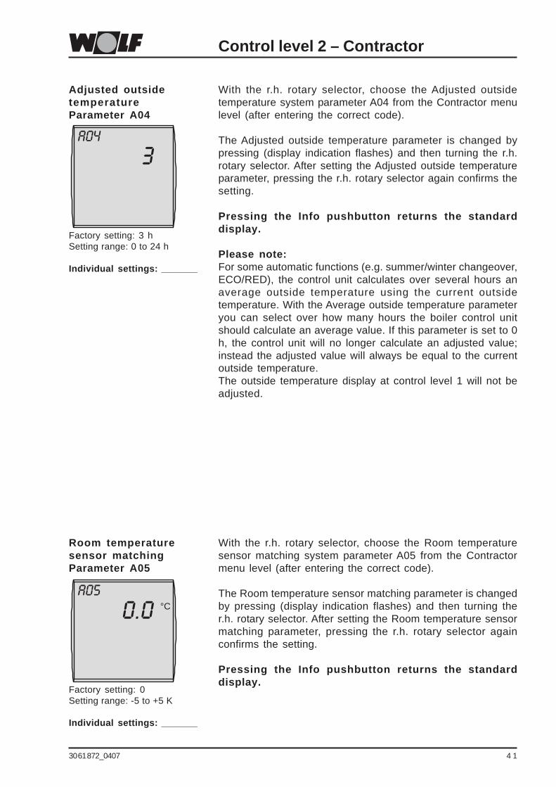
With the r.h. rotary selector, choose the Adjusted outsidetemperature system parameter A04 from the Contractor menulevel (after entering the correct code).
The Adjusted outside temperature parameter is changed bypressing (display indication flashes) and then turning the r.h.rotary selector. After setting the Adjusted outside temperatureparameter, pressing the r.h. rotary selector again confirms thesetting.
Pressing the Info pushbutton returns the standarddisplay.
Please note:For some automatic functions (e.g. summer/winter changeover,ECO/RED), the control unit calculates over several hours anaverage outside temperature using the current outsidetemperature. With the Average outside temperature parameteryou can select over how many hours the boiler control unitshould calculate an average value. If this parameter is set to 0h, the control unit will no longer calculate an adjusted value;instead the adjusted value will always be equal to the currentoutside temperature.The outside temperature display at control level 1 will not beadjusted.
Adjusted outsidetemperatureParameter A04
A04
3
Factory setting: 3 hSetting range: 0 to 24 h
Individual settings: _______
Control level 2 – Contractor
With the r.h. rotary selector, choose the Room temperaturesensor matching system parameter A05 from the Contractormenu level (after entering the correct code).
The Room temperature sensor matching parameter is changedby pressing (display indication flashes) and then turning ther.h. rotary selector. After setting the Room temperature sensormatching parameter, pressing the r.h. rotary selector againconfirms the setting.
Pressing the Info pushbutton returns the standarddisplay.
Room temperaturesensor matchingParameter A05
A05
0.0 °C
Factory setting: 0Setting range: -5 to +5 K
Individual settings: _______

42 30 61 872_0407
With the r.h. rotary selector, choose the External sensor systemparameter A06 from the Contractor menu level (after enteringthe correct code).
The External sensor parameter is changed by pressing (displayindication flashes) and then turning the r.h. rotary selector.After setting the External sensor parameter, pressing the r.h.rotary selector again confirms the setting.
Pressing the Info pushbutton returns the standarddisplay.
Please note:If the programming module is used as remote control fitted intoa wall mounted base, the terminal 5 / 6 of the terminal strip insidethe wall mounting base (see chapter "Installation"), an externalroom temperature sensor or an external outside temperaturesensor can be connected. This sensor can have a functionallocated via the External sensor system parameter A06.
The settings have the following meaning:0 ! External room temperature sensor1 ! External outside temperature sensor
External sensorParameter A06
A06
1
Factory setting: 1Setting range: 0 to 1
Individual settings: _______
Control level 2 – Contractor
Please note:The current display can be changed by + / - 5 K, to match theroom temperature display to the installation conditions or otherthermometers. The corrected display value will be applied to allcalculations of relevant functions.
Example:The remote control indicates a room temperature of 20 °C.In the living area, a temperature of 22 °C is measured with athermometer.The set value must be changed to +2 °C. That way, the actualtemperature measured by the remote control will always beindicated 2 °C higher.

30 61 872_0407 4 3
Control level 2 – Contractor
With the r.h. rotary selector, choose the Pasteurisation functionsystem parameter A07 from the Contractor menu level (afterentering the correct code).
The Pasteurisation function parameter is changed by pressing(display indication flashes) and then turning the r.h. rotaryselector. After setting the Pasteurisation function parameter,pressing the r.h. rotary selector again confirms the setting.
Pressing the Info pushbutton returns the standarddisplay.
Please note:• Systems without solar module:
If pasteurisation has been enabled, the DHW cylinder will beheated to 65 °C during the first cylinder heating of the selectedday. This set temperature will be maintained for one hour.
• Systems with solar module:The pasteurisation function will be safeguarded by the boileror the solar heating system, if pasteurisation has been enabled.
a. Pasteurisation by the solar heating systemThe pasteurisation function via the boiler will be blocked if thesolar yield has achieved a cylinder temperature in excess of65 °C for at least one hour. Blocking the pasteurisation bythe boiler is indicated at the info level STATUS SOL.
b. Pasteurisation by the boilerIf the solar yield is insufficient for a pasteurisation, the setDHW temperature is set to 65 °C for one hour at 18:00 h onthe selected day.
The settings have the following meaning:0 ! Pasteurisation disabled
1 to 7 ! Pasteurisation once a week (1 = Mon; 7 = Sun)8 ! Daily pasteurisation
Pasteurisation functionParameter A07
A07
0
Factory setting: 0Setting range: 1 to 8
Individual settings: _______

44 30 61 872_0407
Control level 2 – Contractor
With the r.h. rotary selector, choose the Service message systemparameter A08 from the Contractor menu level (after enteringthe correct code).
The Service message parameter is changed by pressing(display indication flashes) and then turning the r.h. rotaryselector. After setting the Service message parameter, pressingthe r.h. rotary selector again confirms the setting.
Pressing the Info pushbutton returns the standarddisplay.
Please note:Enabling the Service message parameter, e.g. set value greaterthan 0, the display will show Service after expiry of the selectednumber of weeks. You can acknowledge this message bypressing the Setback pushbutton (control level 1). Afterwards,the cycle restarts again.
The settings have the following meaning:0 weeks ! Service message disabled52 weeks ! Annual service message
Service messageParameter A08
A08
0
Factory setting: 0Setting range: 1 to 104 weeks
Individual settings: _______
With the r.h. rotary selector, choose the Frost protection limitsystem parameter A09 from the Contractor menu level (afterentering the correct code).
The Frost protection limit parameter is changed by pressing(display indication flashes) and then turning the r.h. rotaryselector. After setting the Frost protection limit parameter,pressing the r.h. rotary selector again confirms the setting.
Pressing the Info pushbutton returns the standarddisplay.
The boiler circuit pump operates constantly if the outsidetemperature stays below the selected value.The burner starts and heats the boiler up to the minimum boilerwater temperature, if the boiler water temperature falls belowthe permanently set value of +5 °C.
Note:Only change the factory setting if you can ensure that theheating system and its components will not freeze up at lowoutside temperatures.
Frost protection limitParameter A09
A09
2.0 °C
Factory setting: 2 °CSetting range: -20 to +10 °C
Individual settings: _______

30 61 872_0407 4 5
Control level 2 – Contractor
With the r.h. rotary selector, choose the Parallel DHW operationsystem parameter A10 from the Contractor menu level (afterentering the correct code).
The Parallel DHW operation parameter is changed by pressing(display indication flashes) and then turning the r.h. rotaryselector. After setting the Parallel DHW operation parameter,pressing the r.h. rotary selector again confirms the setting.
Pressing the Info pushbutton returns the standarddisplay.
The boiler circuit pump is switched OFF during DHW cylinderheating with DHW priority (0). The boiler energy will then beused exclusively for heating the DHW cylinder. The cylinderprimary pump will only start, if the boiler water temperature is5 °C higher than the actual cylinder temperature. The burnershuts down and the heating circuit pump is started, as soon asthe cylinder has reached its set temperature. The cylinderprimary pump runs on for the time selected under parameterHG19 (cylinder primary pump run-on time).The heating circuit pump continues to operate in parallel DHWmode (1). The cylinder primary pump starts, if the boiler watertemperature is 5 °C warmer than the cylinder temperature. Thecylinder is fully heated up when the cylinder has reached theselected water temperature. The cylinder primary pump runson for the maximum period selected under parameter HG19(cylinder primary pump run-on time).
In the parallel DHW mode (1), the heating circuit can temporarilybe operated at a higher temperature.
For wall mounted boilers, this parameter has no function.
NB
Parallel DHW operationParameter A10
A10
0
Factory setting: 0Setting range: 0 / 1
Individual settings: _______

46 30 61 872_0407
Control level 2 – Contractor
Function explainedRoom temperature-dependentsummer/winterchangeover
Using room influence, room temperature fluctuations due toexternal heat or cold (e.g. solar irradiation, woodburning stoveor open windows) can be compensated. With room influenceenabled or in case of simple room control, if the room temperatureexceeds the selected set room temperature by 1 K, then thesystem changes over from winter to summer operation, subjectto this parameter being enabled.The summer/winter changeover can be enabled / disabled viathis parameter.
The settings have the following meaning:OFF ! Summer/winter changeover OFFON ! Summer/winter changeover ON
Example 1:The summer/winter changeover (ON) prevents the area beingoverheated, if room influence is enabled and the accommodationis only heated by a boiler.
Example 2:A summer/winter changeover can occur, if a room, where theprogramming module is installed (e.g. living room) is heated by asecond heat source (e.g. a woodburning stove), and roominfluence is enabled. This would result in other rooms getting cold.Remedy: Disable room temperature-dependent summer/winterchangeover (OFF).
Room temperature-dependent summer/winter changeoverParameter A11
A11
ON
Factory setting: ONSetting range: ON / OFF
Individual settings: _______
With the r.h. rotary selector, choose the Room temperature-dependent summer/winter changeover parameter A11 from theContractor menu level (after entering the correct code).
The Room temperature-dependent summer/winter changeoverparameter is set by pressing (display indication flashes) andthen turning the r.h. rotary selector. After changing the Roomtemperature-dependent summer/winter changeover parameter,pressing the r.h. rotary selector again confirms the setting.
Pressing the Info pushbutton returns the standarddisplay.
This parameter is only active if room influence is enabled.

30 61 872_0407 4 7
Control level 2 – Contractor
Setback stopParameter A12
A12
- 16.0 °C
Factory setting: -16 °CSetting range: OFF, -39 to 0 °C
Individual settings: _______
With the r.h. rotary selector, choose the Setback stop systemparameter A12 from the Contractor menu level (after enteringthe correct code).
The Setback stop parameter is changed by pressing (displayindication flashes) and then turning the r.h. rotary selector.After setting the Setback stop parameter, pressing the r.h. rotaryselector again confirms the setting.
Pressing the Info pushbutton returns the standarddisplay.
Please note:The boiler control unit returns from setback mode to heatingmode, if the adjusted outside temperature falls below theselected value.Otherwise, if the adjusted outside temperature lies below theradiator design temperature, the required room temperaturewould not be able to be achieved for a considerable period oftime after the temperature setback.
Example 1:Setting: -16 °CAdjusted outside temperature: -16 °CThere will also be no changeover to setback mode, even outsidethe selected switching times.
Example 2:Setting -16 °CAdjusted outside temperature: -10 °COutside the selected switching times, the system changes fromday mode to setback mode.
Set Setback stop parameter to OFF, if no setback stop isrequired.

48 30 61 872_0407
Control level 2 – Contractor
Minimum DHWtemperatureParameter A13
A13
40.0 °C
Factory setting: 40 °CSetting range: 0 to 40 °C
Individual settings: _______
With the r.h. rotary selector, choose the Minimum DHWtemperature parameter A13 from the Contractor menu level(after entering the correct code).
The Minimum DHW temperature parameter is changed bypressing (display indication flashes) and then turning the r.h.rotary selector. After setting the Minimum DHW temperatureparameter, pressing the r.h. rotary selector again confirms thesetting.
Pressing the Info pushbutton returns the standarddisplay.
Please note:The setting for the minimum DHW temperature is enabled whena solar extension module is connected. This parameter has nofunction for the heating system if no solar module is connected.
The set DHW temperature will be adjusted to the minimum DHWtemperature (parameter A13) until 14:00 h the following day, ifthe solar heating has been completed successfully (selectedDHW temperature is exceeded at the solar cylinder sensor).The boiler provides no cylinder heating, when the selected DHWtemperature is not achieved.Only when the minimum DHW temperature is not achieved andcylinder heating has been enabled by the DHW time program, willthe boiler heat the cylinder to the minimum DHW temperature.
The set DHW temperature remains at the value of the selectedDHW temperature, if solar heating is not completed successfully.
Pressing the pushbutton Single cylinder heating sets the requiredDHW from minimum DHW temperature to DHW temperature(standard settings parameter), even if the solar heating wassuccessful.

30 61 872_0407 4 9
Control level 2 – Contractor
Boiler 1The boiler parameters (e.g. maximum boiler water temperature,input 1, output 1) can be adjusted via the BM programmingmodule. The boiler parameters may vary, subject to the respectiveboiler version.Possible adjustments and explanations regarding the individualparameters are shown in the respective boiler or control unitinstallation instructions.
After selecting the parameter, the details are obtained from theboiler control unit and displayed approx. 5 seconds later.The currently selected value will be shown in the display and canbe modified, subject to the parameter being available in the boilercontrol unit.A display of four lines indicates that the parameter is not availablein the connected boiler control unit.
With the r.h. rotary selector, choose the boiler parameter to bemodified (HG..) from the Contractor menu level (after enteringthe correct code).
The boiler parameter to be modified (HG..) is changed bypressing (display indication flashes) and then turning the r.h.rotary selector. After setting the boiler parameter to be modified(HG..), pressing the r.h. rotary selector again confirms thesetting.
Pressing the Info pushbutton returns the standarddisplay.
Changing the boilerparameters HG...
An incorrect adjustment of these parameters can result in afaulty boiler operation.
NB

50 30 61 872_0407
Boiler parameter overview, Contractor menu(Setting and function in the installation instructions of theboiler or the boiler control unit)
Parameters
HG00 Matching the pipe length
HG01 Burner switching differential
HG02 Low end fan speed HZ
HG03 High end fan speed WW
HG04 High end fan speed HZ
HG06 Pump operating mode
HG07 Boiler circuit pump run-on time
HG08 Maximum limit boiler circuit TV-max.
HG09 Burner cycle block
HG10 eBUS address
HG11 DHW quick start
HG12 Gas type
HG13 Programmable input E1
HG14 Programmable output A1
HG15 Cylinder hysteresis
HG16 Pump rate HK, minimum
HG17 Pump rate HK, maximum
HG19 Cylinder primary pump run-on time
HG20 Max. cylinder heating time
HG21 Minimum boiler temperature TK-min.
HG22 Maximum boiler water temperature TK-max.
HG23 Maximum DHW temperature
HG24 DHW sensor operating mode
HG25 Boiler excess temperature during cylinder heating
HG26 Boiler soft start
HG27 Burner stage during cylinder heating
HG28 Burner operating mode
HG29 Modulation block
HG30 Modulation dynamic
HG31 Blocking time, burner stage 2
HG32 Return temperature raising
HG33 Hysteresis time
HG34 eBUS feed
HG50 Test functions
Control level 2 – Contractor

30 61 872_0407 5 1
Control level 2 – Contractor
Mix valve 1 The menu level Mixer will not be displayed if only heatingcircuits are controlled (no mixer circuit installed).
The parameters for mixer circuits 1-7 (e.g. configuration, heatingcurve gap) can be adjusted via the BM programming module.Possible adjustments and explanations regarding the individualparameters are shown in the installation instructions of the mixermodule or boiler.
After selecting the parameter, the details are obtained from themixer module and displayed approx. 5 seconds later.
With the r.h. rotary selector, choose the mixer parameter to bemodified (MI..) from the Contractor menu level (after enteringthe correct code).
The mixer parameter to be modified (MI..) is changed by pressing(display indication flashes) and then turning the r.h. rotaryselector. After setting the mixer parameter to be modified (MI..),pressing the r.h. rotary selector again confirms the setting.
Pressing the Info pushbutton returns the standarddisplay.
Changing the mixerparameter MI...
Mixer parameter overview, Contractor menu(Setting and function in the installation instructions of themixer module or the boiler control unit.)
ParametersMI 01 Minimum limit mixer circuit TV-min.
MI 02 Maximum limit mixer circuit TV-max.
MI 03 Heating curve gap
MI 04 Screed drying
MI 05 Configuration
MI 06 Mixer circuit pump run-on time
MI 07 P range, mixer
MI 08 Set return temperature
MI 09 Max. cylinder heating time
MI 10 eBUS feed
MI 11 Hysteresis, bypass sensor
MI 12 Primary pump block
MI 13 Primary pump run-on time
MI 14 Constant temperature
MI 15 dTAus (shutdown differential)
MI 16 dTEin (start-up differential)
MI 17 Excess boiler temperature during cylinder heating
MI SO Relay test

52 30 61 872_0407
Control level – Contractor
Solar The menu level MSolar will not be displayed if onlyheating circuits are controlled (no solar circuit installed).
Solar module parameters (e.g. start-up differential, shutdowndifferential) can be adjusted via the BM programming module.Possible adjustments and explanations regarding the individualparameters are shown in the solar module installation instructions.
After selecting the parameter, the details are obtained from thesolar module and displayed approx. 5 seconds later.
With the r.h. rotary selector, choose the solar parameter to bemodified (SOL..) from the Contractor menu level (after enteringthe correct code).
The solar parameter to be modified (SOL..) is changed bypressing (display indication flashes) and then turning the r.h.rotary selector. After setting the solar parameter to be modified(SOL..), pressing the r.h. rotary selector again confirms thesetting.
Pressing the Info pushbutton returns the standarddisplay.
Changing the mixerparameter SOL...
Solar parameter overview, Contractor menu(Setting and function in the installation instructions of thesolar module.)
ParameterSOL 01 Start-up differential
SOL 02 Shutdown differential
SOL 03 Collector protection function
SOL 04 Critical collector temperature
SOL 05 Maximum collector temperature
SOL 06 Maximum cylinder temperature
SOL 07 Cylinder allocation
SOL 08 Capturing the heat volume
SOL 09 Pulse transducer, flow rate
SOL 10 Medium selection
SOL 11 eBUS feed
SOL SO Relay test

30 61 872_0407 5 3
Control level 2 – Contractor
OTHERS Other parameters (e.g. screed drying) can be adjusted via theBM programming module.Possible adjustments and explanationsregarding the individual parameters are shown in the respectiveboiler or control unit installation instructions.
With the r.h. rotary selector, choose the parameter to be modified(SO..) from the Contractor menu level (after entering the correctcode).
The parameter to be modified (SO..) is changed by pressing(display indication flashes) and then turning the r.h. rotaryselector. After setting the parameter to be modified (SO..),pressing the r.h. rotary selector again confirms the setting.
Pressing the Info pushbutton returns the standarddisplay.
Changing otherparameters SO...
Other parameter overview, Contractor menu
Parameter
SO 01 N / A
SO 02 N / A
SO 03 N / A
SO 04 N / A
SO 05 N / A
SO 06 N / A
SO 07 Screed drying, direct heating circuit
SO 08 Screed temperature

54 30 61 872_0407
If an underfloor heating system is started for the first time innew buildings, the set flow temperature may, as an option, becontrolled independent of the outside temperature either to aconstant value or to control the set flow temperature inaccordance with an automatic screed drying program.If this function has been enabled (setting 1 or 2), it can beterminated by resetting parameter SO 07 to 0.
SO 07 = 0 no functionSO 07 = 1 constant temperature heating circuitThe heating circuit is heated to the set flow temperature. Theset flow temperature is regulated permanently to thetemperature selected in parameter SO 08.
To change the constant temperature for screed drying, proceedas follows:1. Press the r.h. rotary selector2. Turn the r.h. rotary selector clockwise until EXPERT is
displayed.3. Press the r.h. rotary selector.4. CODE-NO will be displayed.5. Press the r.h. rotary selector to be able to enter the
contractor code.6. Set code to 1.7. Press the r.h. rotary selector to be able to confirm the code.8. Turn the r.h. rotary selector clockwise until OTHERS is
displayed.9. Press the r.h. rotary selector.10. Turn the r.h. rotary selector clockwise until SO 08 is displayed.11. Press the r.h. rotary selector.12. Select the required constant temperature in accordance
with the heat-up curve by turning the r.h. rotary selector.13. Press the r.h. rotary selector.14. Press the Info pushbutton to return to the standard display.
SO 07 = 2 Screed drying functionFor the first two days, the set flow temperature will remainconstant at 25 °C. It will then be automatically raised every day(at 0.00 h) by 5 °C up to the screed temperature (SO 08). Thattemperature will then be held for two days. Subsequently, theflow temperature is automatically reduced again in 5 °C stepsper day to 25 °C. The program sequence is terminated after afurther two days.
Screed drying, directheating circuitParameter SO 07Parameter SO 08
Control level 2 – Contractor

30 61 872_0407 5 5
Reset Observe the following steps to implement a reset:- The ON / OFF switch of the boiler control unit must be set
to O (OFF).- Press and hold down the rotary selector of the programming
module whilst setting the ON / OFF switch to I (ON).- Keep holding down the reset button for at least 2 seconds after
the system has started.
All parameters (individual settings) are returned to their factorysettings by a reset. As a check, EEPROM will be shownafterwards for approx. 3 seconds in the programming moduledisplay.
Control level 2 – Contractor / Reset
Agree the time sequence and the maximum flow temperaturewith the screed contractor, otherwise the screed may bedamaged, particularly through cracking.
The screed drying program continues uninterrupted after apower failure. The remaining time in days is shown on thedisplay.
Fig.:Flow temperature progress over time during screed drying(parameter SO 08 = 50 °C)
120
25
30
35
40
45
50
55
2 3 4 5 6 7 8 9 10 11 12 13 14 15 16 17F
low
tem
pera
ture
(°C
)Screed drying runtime (days)
NB

56 30 61 872_0407
Parameters Setting range Factory Individualsetting setting
Time 0 to 24 h -Day 1 (Mon) to 7 (Sun) -Time program 1 / 2 / 3 1Day temp. Boiler circuit 5 to 30 °C 20 °C
Mixer circuit 1 5 to 30 °C 20 °CMixer circuit 2 5 to 30 °C 20 °CMixer circuit 3 5 to 30 °C 20 °CMixer circuit 4 5 to 30 °C 20 °CMixer circuit 5 5 to 30 °C 20 °CMixer circuit 6 5 to 30 °C 20 °CMixer circuit 7 5 to 30 °C 20 °C
Setback temp. Boiler circuit 5 to 30 °C 16 °CMixer circuit 1 5 to 30 °C 16 °CMixer circuit 2 5 to 30 °C 16 °CMixer circuit 3 5 to 30 °C 16 °CMixer circuit 4 5 to 30 °C 16 °CMixer circuit 5 5 to 30 °C 16 °CMixer circuit 6 5 to 30 °C 16 °CMixer circuit 7 5 to 30 °C 16 °C
Heating curve Boiler circuit 0 to 3.0 1.2Mixer circuit 1 0 to 3.0 0.8Mixer circuit 2 0 to 3.0 0.8Mixer circuit 3 0 to 3.0 0.8Mixer circuit 4 0 to 3.0 0.8Mixer circuit 5 0 to 3.0 0.8Mixer circuit 6 0 to 3.0 0.8Mixer circuit 7 0 to 3.0 0.8
Room influence Boiler circuit ON / OFF OFFMixer circuit 1 ON / OFF OFFMixer circuit 2 ON / OFF OFFMixer circuit 3 ON / OFF OFFMixer circuit 4 ON / OFF OFFMixer circuit 5 ON / OFF OFFMixer circuit 6 ON / OFF OFFMixer circuit 7 ON / OFF OFF
Wolf recommends you complete the settings report carefully and to keep it safe to enable a quicksolution to be found during service and in case of a full reset.
Settings reportStandard settings parameters
For further parameters, see next page.

30 61 872_0407 5 7
Parameters Setting range Factory Individualsetting setting
Summer/winter changeoverBoiler circuit 0 to 40 °C 20 °CMixer circuit 1 0 to 40 °C 20 °CMixer circuit 2 0 to 40 °C 20 °CMixer circuit 3 0 to 40 °C 20 °CMixer circuit 4 0 to 40 °C 20 °CMixer circuit 5 0 to 40 °C 20 °CMixer circuit 6 0 to 40 °C 20 °CMixer circuit 7 0 to 40 °C 20 °C
ECO/RED Boiler circuit -10 to 40 °C 10 °CMixer circuit 1 -10 to 40 °C 10 °CMixer circuit 2 -10 to 40 °C 10 °CMixer circuit 3 -10 to 40 °C 10 °CMixer circuit 4 -10 to 40 °C 10 °CMixer circuit 5 -10 to 40 °C 10 °CMixer circuit 6 -10 to 40 °C 10 °CMixer circuit 7 -10 to 40 °C 10 °C
DHW temperatureFreestanding boiler 15 to 60 °C 60 °CWall mounted boilerwith cylinder 15 to 65 °C 60 °CWall mountedcombi boiler 40 to 65 °C 60 °C
Language German, English, GermanFrench, Dutch,
Spanish,Portuguese,
Italian, Czech,Polish, Slovakian,
Hungarian,Russian,
Greek, Turkish
Settings reportStandard settings parameters

58 30 61 872_0407
Wolf recommends you complete the settings report carefully and to keep it safe to enable a quicksolution to be found during service and in case of a full reset.
Tim
eB
lock
Sw
itch
.H
CM
ixer
1M
ixer
2M
ixer
3M
ixer
4p
rog
ram
tim
eO
NO
FFO
NO
FFO
NO
FFO
NO
FFO
NO
FFTi
me
prog
. 1M
o-Fr
1 2 3S
a-S
u1 2 3
Tim
e pr
og. 2
Mo-
Fr1 2 3
Sa-
Su
1 2 3Ti
me
prog
. 3M
ON
1 2 3TU
E1 2 3
WED
1 2 3TH
U1 2 3
FRI
1 2 3S
AT
1 2 3SU
N1 2 3
For further time programs, see next page.
Settings report, time programs

30 61 872_04075
9
Time Block Switch. Mixer 5 Mixer 6 Mixer 7 DHW DHW circ. lineprogram time ON OFF ON OFF ON OFF ON OFF ON OFF
Time prog. 1 Mo-Fr 123
Sa-Su 123
Time prog. 2 Mo-Fr 123
Sa-Su 123
Time prog. 3 MON 123
TUE 123
WED 123
THU 123
FRI 123
SAT 123
SUN 123
Settin
gs rep
ort, tim
e pro
gram
s

60 30 61 872_0407
Operating mode, boiler status / Settingsreport, system parameters
Parameter Setting range Factory Individualsetting setting
A00 Room influence 1 to 20 K / K 4 K / KA01 Heat-up optimisation 0 / 1 0A02 Max. heat-up time 0 to 180 min 0A03 Required heat-up time - - -A04 Adjusted outside temp. sensor 0 to 24 h 3 hA05 Room sensor matching -5 to +5 K 0 KA06 External room temp. sensor 0 to 1 1A07 Pasteurisation function 0 to 8 0A08 Service message 0 to 104 weeks 0A09 Frost protection level -20 to +10 °C +2 °CA10 Parallel DHW operation 0 / 1 0A11 Room temperature-dependent OFF / ON ON
summer/winter changeoverA12 Setback stop OFF, -39 to 0°C -16 °CA13 Minimum DHW temp. 0 to 60 °C 40 °C
Wolf recommends you complete the settings report carefully and to keep it safe to enable a quicksolution to be found during service and in case of a full reset.
Operating modeBoiler status
Boiler status0 Standby
1 Emission test mode
2 Soft start
3 Heat demand (heating mode)
5 Heat demand with cycle block
6 Cycle block
7 Frost protection – heating
8 Soft start
11 DHW draw-off
12 DHW reheating
13 Minimum combi time
14 DHW quick start reheating
15 Cylinder mode
16 Frost protection – cylinder
17 Pump run-on – cylinder
18 Boil dry
19 dt output reduction
20 Parallel cylinder mode
21 Max. cylinder heating time exceeded
22 Sensor operating mode 2, contact closed
23 Sensor operating mode 3, contact closed

30 61 872_0407 6 1
NTCSensor resistances
Boiler sensor, cylinder sensor, solar cylinder sensor, outsidetemperature sensor, flow sensor, central sensor
Sensor resistances
Temp. Resist. Temp. Resist. Temp. Resist. Temp. Resist.
°C Ohm °C Ohm °C Ohm °C Ohm-21 51393 14 8233 49 1870 84 552-20 48487 15 7857 50 1800 85 535-19 45762 16 7501 51 1733 86 519-18 43207 17 7162 52 1669 87 503-17 40810 18 6841 53 1608 88 487-16 38560 19 6536 54 1549 89 472-15 36447 20 6247 55 1493 90 458-14 34463 21 5972 56 1438 91 444-13 32599 22 5710 57 1387 92 431-12 30846 23 5461 58 1337 93 418-11 29198 24 5225 59 1289 94 406-10 27648 25 5000 60 1244 95 393-9 26189 26 4786 61 1200 96 382-8 24816 27 4582 62 1158 97 371-7 23523 28 4388 63 1117 98 360-6 22305 29 4204 64 1078 99 349-5 21157 30 4028 65 1041 100 339-4 20075 31 3860 66 1005 101 330-3 19054 32 3701 67 971 102 320-2 18091 33 3549 68 938 103 311-1 17183 34 3403 69 906 104 3020 16325 35 3265 70 876 105 2941 15515 36 3133 71 846 106 2852 14750 37 3007 72 818 107 2773 14027 38 2887 73 791 108 2704 13344 39 2772 74 765 109 2625 12697 40 2662 75 740 110 2556 12086 41 2558 76 716 111 2487 11508 42 2458 77 693 112 2418 10961 43 2362 78 670 113 2359 10442 44 2271 79 649 114 228
10 9952 45 2183 80 628 115 22211 9487 46 2100 81 608 116 21612 9046 47 2020 82 589 117 21113 8629 48 1944 83 570 118 205

62 30 61 872_0407
Fault messages
If a fault is indicated by the signal ring of the control unit flashing red, a fault code is displayedvia the Wolf-control accessory with eBUS capability that allows a cause to be allocated usingthe following table.This list of fault messages is designed to allow your heating contractor to trace the fault moreeasily.
Note: Faults that are not listed may be faults of the air-condition or ventilation control.
1 TB excess temperature The external temp. limiter has shut down the system.
4 No flame established No flame established during the burner start
5 Flame failure during Flame failure during the safety time
6 TW excess temperature The boiler water temp. has exceeded the limitfor the TW (e.g. 95 °C)
7 STBA - excess temperature The temperature limiter has shut down the system
8 No flue gas damper response Flue gas damper or damper feedback faulty
11 False flame indication A flame is recognised before the burner starts
12 Boiler sensor faulty The boiler water temp. sensor or sensor lead is faulty
13 Flue gas temp. sensor faulty The flue gas sensor or sensor lead is faulty
14 Cylinder sensor faulty The DHW temp. sensor or sensor lead is faulty
15 Outside temperature sensor The outside temperature sensor is faulty (shortfaulty circuit or break, wireless reception interference,
battery of the wireless outside temperature sensordead), power supply boiler interrupted or boilerfuse blown / tripped
16 Return sensor faulty The return sensor or the sensor lead is faulty
17 Fault modulation current The modulation current is outside its set range
20 Faulty gas valve V1 The gas valve is faulty
21 Faulty gas valve V2 The gas valve is faulty
22 Lack of air The air pressure switch does not switch ON
23 Faulty air pressure switch The air pressure switch does not switch OFF
24 Gas fan, fault The gas fan does not reach the requiredpre-purging speed
25 Gas fan, fault The fan does not reach the ignition speed
26 Gas fan, fault The fan does not stop
30 CRC fault, boiler Internal device error
31 CRC fault, burner Internal device error
32 Power failure 24 V 24 V power supply faulty
No. Fault Cause

30 61 872_0407 6 3
33 CRC fault, factory setting Internal device error
34 CRC fault, BCC Faulty boiler coding card
35 BCC missing Boiler coding card was removed
36 CRC fault, BCC Faulty boiler coding card
37 Incorrect BCC The boiler coding card is incompatible with thecontrol unit PCB
38 BCC no. invalid Faulty boiler coding card
39 BCC system error Faulty boiler coding card
40 Faulty flow limiter The flow limiter does not switch OFF or ON
41 Faulty flow limiter The return temperature is at least 12 K higher thanthe flow temperature
52 Max. cylinder heating time The cylinder heating takes longer than permittedexceeded
60 Siphon back pressure The siphon or the flue gas system is blocked
61 Flue gas system back pressure The flue gas system is blocked
64 Pulse transducer faulty The pulse transducer of the solar module is faultyor the solar heating system has no circulation
70 Mixer circuit sensor faulty The mixer circuit sensor or the sensor lead is faulty
71 Sensor faulty The cylinder sensor of the solar module or themulti-function sensor input E1 of the mixer moduleis faulty
72 Return sensor faulty The return sensor of the sensor module is faulty
76 Cylinder sensor faulty The cylinder sensor or the sensor lead is faulty
78 Central sensor faulty The central sensor or the sensor lead is faulty
79 Sensor faulty The multi-function sensor input E1 of the boilercontrol units R1, R2, R3 or the multi-function sensorinput E2 of the mixer module or the collector sensorof the solar moduleis faulty
80 Outside temperature sensor The outside temperature sensor or the sensor leadaccessory controller is faulty at the accessory controller is faulty
81 EEPROM fault Internal equipment error at the accessory controller
82 Oil level fault The oil tank is empty or check the oil level transducer
91 Fault eBUS parameter One BUS address was allocated more than once
97 Bypass pump faulty The bypass pump of the mixer module is faulty
No. Fault Cause
Fault messages

64 30 61 872_0407
Specification
Specification Supply voltage: eBUS 15-24 V
Power consumption: Max. 0.5 W
Protection: Wall mounting base: IP 30Boiler: as per control unit protectionlevel
Battery backup: > 48 h
Ambient temp.: 0....50 °C
Storage temperature: -20....+60 °C
Data memory: EEPROM (non-volatile)
Wolf GmbH · Postfach 1380 · D-84048 Mainburg · Tel. +49-8751/74-0 · Fax +49-8751/741600 · Internet: www.wolf-heiztechnik.de