Technical Feasibility Assessment of LED Roadway...
120
Technical Feasibility Assessment of LED Roadway Lighting on the Golden Gate Bridge September 2012 Prepared for: Solid-State Lighting Program Building Technologies Program Ofce of Energy Efciency and Renewable Energy U.S. Department of Energy Prepared by: Pacifc Northwest National Laboratory © Golden Gate Bridge Highway & Transportation District
Transcript of Technical Feasibility Assessment of LED Roadway...

Technical Feasibility Assessment of LED Roadway Lighting on the Golden Gate Bridge
September 2012
Prepared for:
Solid-State Lighting Program Building Technologies Program Office of Energy Efficiency and Renewable Energy U.S. Department of Energy
Prepared by:
Pacific Northwest National Laboratory
© G
olde
n G
ate
Brid
ge H
ighw
ay &
Tra
nspo
rtat
ion
Dis
tric
t


PNNL-21894
Technical Feasibility Assessment of LED Roadway Lighting on the
Golden Gate Bridge
JR Tuenge
September 2012
Prepared for the U.S. Department of Energy under Contract DE-AC05-76RL01830
Pacific Northwest National Laboratory Richland, Washington 99352
Phot
o cr
edit:
© M
oulin
Stu
dios
Phot
o cr
edit:
© M
oulin
Stu
dios

iii
Preface
This document is a report of observations and analysis performed in preparation for a potential lighting demonstration project to be conducted in cooperation with the U.S. Department of Energy (DOE) GATEWAY Demonstration Program. The program supports demonstrations of high-performance solid-state lighting (SSL) products in order to develop empirical data and experience with in-the-field applications of this advanced lighting technology. The DOE GATEWAY Demonstration Program focuses on providing a source of independent, third-party data for use in decision-making by lighting users and professionals; this data should be considered in combination with other information relevant to the particular site and application under examination. Each GATEWAY Demonstration compares SSL products against the incumbent technologies used in that location. Depending on available information and circumstances, the SSL product may also be compared to alternate lighting technologies. Though products demonstrated in the GATEWAY program have been prescreened for performance, DOE does not endorse any commercial product or in any way guarantee that users will achieve the same results through use of these products.

iv
Executive Summary
Following is an assessment of the technical feasibility of LED roadway lighting on the Golden Gate Bridge. Economic feasibility is beyond the scope of this report. The analysis was supported by these organizations and individuals:
• The Golden Gate Bridge Highway & Transportation District (GGB), represented by Kevin Raddatz
• Pacific Gas & Electric (PG&E), represented by Dave Alexander and Jack D’Angelo • The DOE GATEWAY Demonstration program, represented by Bruce Kinzey and
Jason Tuenge of the Pacific Northwest National Laboratory (PNNL).
Subsequent to preliminary investigations by the GGB, in coordination with PG&E, the GATEWAY Demonstration program was asked to evaluate the feasibility of replacing existing roadway lighting on the bridge with products utilizing LED technology. GGB and PG&E also indicated interest in induction (i.e., electrodeless fluorescent) technology, since both light source types can feature rated lifetimes significantly exceeding those of the existing high-pressure sodium (HPS) and low-pressure sodium (LPS) products. Regardless of the technology chosen, the goal of the study was to identify solutions which would reduce maintenance and energy use without compromising the quantity or quality of existing illumination.
It is assumed that existing light levels must be preserved. A new analysis would need to be performed if the GGB ultimately determines reduced illumination would be acceptable. For example, if a product which reduces existing light levels by over 50% is deemed adequate, LED products matching this reduced illumination should be sought. This would enable the use of lower wattage products, thereby increasing energy savings and improving the feasibility of LED technology in this application.
Photometric and colorimetric analyses were performed based on manufacturer-provided data for commercially-available alternatives to the existing roadway luminaires, supplemented by laboratory testing of the special bridge paint and the historic amber-lensed shoebox luminaire type. It was determined that induction technology does not appear to represent a viable alternative for the roadway luminaires in this application; any energy savings would be attributable to a reduction in light levels. Although no suitable LED retrofit kits were identified for installation within existing luminaire housings, several complete LED luminaires were found to offer energy savings of 6-18%, suggesting custom LED retrofit kits could be developed to match or exceed the performance of the existing shoeboxes. Luminaires utilizing ceramic metal halide (CMH) were also evaluated, and some were found to offer 28% energy savings, but these products might actually increase maintenance due to the shorter rated lamp life.
Color is a primary consideration for this project. Whereas the light emitted by the existing luminaires is yellow or very yellowish in appearance, the light emitted by the alternative technologies considered can be more accurately described as white in appearance. Based on the findings of this assessment, it is recommended that relatively inexpensive mock-ups of CMH products be performed to determine whether a whiter light would be appropriate in this application. If whiter light is deemed acceptable—or even preferable—this will increase the viability of LED alternatives by allowing for the use of more efficacious products. Performance criteria would then need to be developed to inform the design and evaluation of

v
custom retrofit kits; guidance is offered in the Conclusions section to assist in the development of such specifications.
Although no suitable commercially-available LED product was identified, it appears feasible to develop an LED retrofit kit which would save energy while maintaining HPS light levels. However, the following issues will present challenges for manufacturers of custom retrofit kits and will require substantial coordination with the GGB project team:
• A carefully selected mixture of differently-colored LEDs may be required to avoid a greenish hue when operated behind the amber lens
• Since different types of LEDs may degrade at different rates, products incorporating more than one type of LED may require specialized electronics to prevent color shift over time
• Retrofit kits must be tested in situ (in the existing shoebox housing) to capture thermal effects on photometry, colorimetry, and ISTMT
• Retrofit kits must be securely mounted in the existing housing and demonstrate adequate resistance to vibration
• The added weight of retrofit kits must be determined and approved by GGB to ensure the existing poles and mounting arms are not overloaded.
There does not yet appear to be a simple means of reducing energy use and maintenance while preserving the quality and quantity of illumination for this historic landmark. Analysis provided in this report was completed in May 2012; although LED technologies are expected to become increasingly viable over time, and product mock-ups may reveal near-term solutions, some options not currently considered by GGB may ultimately merit evaluation. For example, it would be preferable in terms of performance to simply replace existing luminaires (some of which may already be nearing end of life) with fully-integrated LED or CMH luminaires rather than replacing internal components. Among other benefits, this would allow reputable manufacturers to offer standard warranties for their products. Similarly, the amber lenses might be reformulated such that they do not render white light sources in a greenish cast, thereby allowing the use of off-the-shelf LED or CMH products. Last, it should be noted that the existing amber-lensed shoeboxes bear no daytime resemblance to the LPS luminaires originally used to light the roadway.
vi
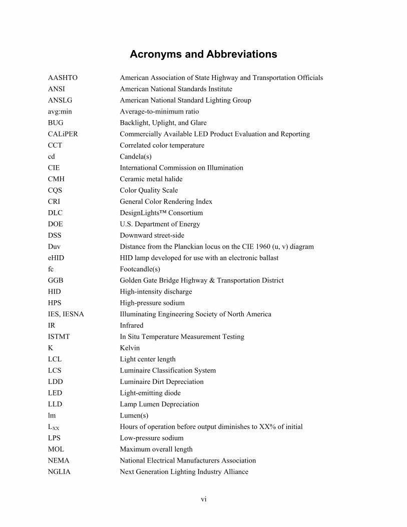
Acronyms and Abbreviations
AASHTO American Association of State Highway and Transportation Officials ANSI American National Standards Institute ANSLG American National Standard Lighting Group avg:min Average-to-minimum ratio BUG Backlight, Uplight, and Glare CALiPER Commercially Available LED Product Evaluation and Reporting CCT Correlated color temperature cd Candela(s) CIE International Commission on Illumination CMH Ceramic metal halide CQS Color Quality Scale CRI General Color Rendering Index DLC DesignLights™ Consortium DOE U.S. Department of Energy DSS Downward street-side Duv Distance from the Planckian locus on the CIE 1960 (u, v) diagram eHID HID lamp developed for use with an electronic ballast fc Footcandle(s) GGB Golden Gate Bridge Highway & Transportation District HID High-intensity discharge HPS High-pressure sodium IES, IESNA Illuminating Engineering Society of North America IR Infrared ISTMT In Situ Temperature Measurement Testing K Kelvin LCL Light center length LCS Luminaire Classification System LDD Luminaire Dirt Depreciation LED Light-emitting diode LLD Lamp Lumen Depreciation lm Lumen(s) LXX Hours of operation before output diminishes to XX% of initial LPS Low-pressure sodium MOL Maximum overall length NEMA National Electrical Manufacturers Association NGLIA Next Generation Lighting Industry Alliance

vii
NIST National Institute of Standards and Technology NRTL Nationally Recognized Testing Laboratory NVLAP National Voluntary Laboratory Accreditation Program pcLED Phosphor-converted LED PG&E Pacific Gas & Electric Co. PNNL Pacific Northwest National Laboratory QGG Qi modified for GGB paint Qi CQS individual score R9 Special Color Rendering Index for Test Color Sample “Strong Red” R10 Special Color Rendering Index for Test Color Sample “Strong Yellow” Ra General Color Rendering Index RGG Ri modified for GGB paint Ri Special Color Rendering Index S/P Scotopic/Photopic SPD Spectral power distribution SRD Spectral reflectance distribution STD Spectral transmittance distribution SSL Solid-state lighting TCS Test Color Sample Ts In situ case temperature for the device under testing UV Ultraviolet V(λ) Photopic luminous efficiency function W Watt(s)


ix
Contents
Preface .............................................................................................................................................. iii Executive Summary ........................................................................................................................... iv Acronyms and Abbreviations ............................................................................................................ vi 1.0 Introduction ............................................................................................................................. 1.1 2.0 Color Considerations ............................................................................................................... 2.1 3.0 Shoebox Performance—HPS (Existing) .................................................................................. 3.1 4.0 Shoebox Performance—Induction........................................................................................... 4.1 5.0 Shoebox Performance—LED .................................................................................................. 5.1 6.0 Shoebox Performance—Other Technologies .......................................................................... 6.1 7.0 Cobrahead Alternatives ........................................................................................................... 7.1 8.0 Experimenting with CCT ......................................................................................................... 8.1 9.0 Conclusions ............................................................................................................................. 9.1 10.0 References ............................................................................................................................. 10.1 Appendix A Excerpts from the GGB Online Research Library ..................................................... A.1 Appendix B Paint Sample Test Data ............................................................................................... B.1 Appendix C Amber Lens Specification .......................................................................................... C.1 Appendix D HPS Shoebox Test Data—Lens A .............................................................................. D.1 Appendix E HPS Shoebox Test Data—Lens B .............................................................................. E.1 Appendix F HPS Shoebox Test Data—No Lens ............................................................................. F.1 Appendix G HPS Shoebox Test Data—Bare Lamp ....................................................................... G.1 Appendix H Excerpts from PG&E and DLC QPL Websites .......................................................... H.1 Appendix I Sample LED Efficacies at 3000 and 4000 K ................................................................ I.1


1.1
1.0 Introduction
The original roadway luminaires on the bridge, visible in the photo which precedes the Preface, incorporated low-pressure sodium (LPS) lamps.1 These LPS luminaires, which featured curved reflectors resembling the wings of a bird in flight, were replaced in 1972 with the shoebox-style luminaires shown in Figure 1.0.
Figure 1.0. Existing HPS luminaire with amber lens (Photo credit: PG&E)
The yellowish-white light emitted by the high-pressure sodium (HPS) lamps used in the shoeboxes was somewhat broader in spectrum than the essentially monochromatic yellowish-orange light emitted by LPS. Consequently, an amber lens was incorporated into the shoebox housings to filter light and thereby more closely match the light emitted by post-top LPS luminaires still bounding the sidewalk around each tower base. HPS floodlighting luminaires with spectrally neutral (rather than amber) lenses were subsequently installed for decorative tower lighting in 1987.2 Due to their combined function in above-roadway bridge illumination, these three existing luminaire types—shown together in Figure 1.1—must be considered as a system:
1. Floodlights with 400 W HPS lamps for decorative up-lighting of the two towers, indicated with a green arrow
2. Post-tops with 35 W LPS lamps for diffuse fill lighting of tower bases and adjacent sidewalks, indicated with a magenta arrow
3. Shoeboxes with 250 W HPS lamps and amber lenses for illumination of the roadway and sidewalks, indicated with a yellow arrow.
1 The website (http://www.goldengatebridge.org/research/factsGGBLighting.php) was accessed on December 30, 2011, and archived in Appendix A. Note that a horizontal plate appears to have been installed immediately above the lamp sometime after the original construction. 2 The color of the floodlight lenses varies from neutral to slightly yellowish. It is assumed any yellowness of these lenses is attributable to deterioration from exposure to UV and IR radiation.

1.2
Figure 1.1. Three existing above-roadway luminaire types
(Photo credit: PG&E)
Figure 1.2 shows the combined effect of the bridge lighting system, alongside a photograph of an earlier mock-up using searchlights. The bridge was designated as California Historical Landmark No. 974 in 1990, effectively precluding future replacement of visible luminaire components such as the amber lens on the shoeboxes.3
3 For more information, visit http://ohp.parks.ca.gov.

1.3
Phot
o cr
edit:
San
Fra
ncis
co H
isto
ry C
ente
r, Sa
n Fr
anci
sco
Publ
ic L
ibra
ry
Phot
o cr
edit:
© R
on N
iebr
ugge
Figure 1.2. Tower floodlighting mock-up in 1947 (left) and current installation (right)
The ten cobrahead-style roadway luminaires at the south end of the bridge—pictured in Figure 1.3—cast light onto the painted guardrails and thus are also considered as part of the analysis. This fourth luminaire type utilizes 250 W HPS lamps.
Figure 1.3. First ten cobraheads at south end of bridge (Photo credit: Google)


2.1
2.0 Color Considerations
Color is a primary concern for this national landmark, and must be considered when evaluating lighting products. According to a report issued by the bridge architect prior to completion of construction, darkness would be preferable to poor color quality:
“The color of the bridge is unhesitatingly put forward as of more importance than the illumination [of the painted structure]. If this possible economy in current [i.e., electricity] consumption is a controlling consideration, then the recommendation is to abandon decorative illumination and preserve the right color [of paint as viewed under daylight].” (GGB 1935)
Roadway lighting is primarily directed at the drivelanes and sidewalks, but some light from roadway luminaires can and should illuminate the specially painted surfaces of the bridge, including the handrails and the bases of the two towers. Even the utilitarian cobraheads at the south end of the bridge will illuminate the painted guardrails, and thus should be evaluated for color characteristics.
“While the roadway lighting is installed for practical purposes, it will have decorative value as well. The long line of yellow glow marking the roadway will serve as the one constant bond uniting the various parts of the structure.” (GGB 1935)
Care should be taken to ensure the apparent color of the towers is acceptably close to the rest of the like-painted surfaces of the bridge. However, differences in color characteristics between the four existing luminaire types are likely mitigated somewhat by the inevitable variation in paint color across the bridge, attributable to manufacturing tolerances and weathering.
“the irregular variation in tone due to repaintings will have positive value as picturesqueness […] the magnitude of the structure and the great distances separating its parts could absorb considerable of the kind of variation of tone and ‘weathering’ that we admire in the great monuments of the past.” (GGB 1935)
Basic color criteria can be summarized as follows: • Products must render the color of the bridge paint in a uniform and appealing manner • The luminous portions of luminaires should appear similar in color when viewed at night.
Two metrics are commonly applied to lighting products when evaluating color: the Color Rendering Index (CRI) and correlated color temperature (CCT).1 CRI is poor for HPS (rated at ∼ 21 out of a possible score of 100) and terrible for LPS (often reported as zero but actually negative in value), so other technologies such as LED and induction generally represent improvements in this aspect. CCT, reported in kelvin (K), provides an indication of hue for white light sources. Lower CCTs (e.g., 2100 K for HPS) indicate a yellowish-white appearance, whereas higher CCTs (e.g., 6500 K for daylight) indicate a bluish-white appearance. CRI and other color rendering metrics should not be compared between products differing widely in CCT.
1 For more on these and other color metrics, see the “LED Color Characteristics” fact sheet, available online at www.ssl.energy.gov/factsheets.html.

2.2
CCT is often supplemented with another metric, Duv, to ensure products do not shift toward greenish or pinkish hues (ANSLG 2008). It is not clear whether Duv is relevant at very low CCTs beyond the typical range of light sources considered white in appearance. Although CCT and Duv do not perfectly capture the color appearance of a light source when viewed directly, these metrics serve as a good starting point in preliminary product evaluation. By contrast, the CRI metric may not be particularly relevant for this application, given the current acceptance of very low values on this and most other roadways (DOE 2011).
To ensure consistent color across the bridge, CCT should be fairly consistent across all four luminaire types, and—depending on the direction of drift—Duv generally should not be allowed to fall far outside ANSI tolerances (ANSI 2011).2 This is significant in terms of energy savings because within any given LED product family, and given equal drive current and CRI, efficacy is largely a function of CCT. Figure 2.0 summarizes sample data from Philips-Hadco (see Appendix I), showing minimal differences in efficacy between 4000 and 5700 K. By contrast, the efficacy for this product family at 3000 K is on average 26% lower than at 4000 K, outweighing other factors such as the choice of optical system (spatial distribution of light). Consequently, the ability of LED products to outperform HPS may greatly depend on the range of CCTs deemed appropriate for this application.
Figure 2.0. Hadco LED efficacy as a function of CCT
The perceived color of the painted surfaces is a function of the spectral power distribution (SPD) of incident light and the spectral reflectance distribution (SRD) of the paint. Whereas the SPDs of the LPS post-top and HPS floodlights were estimated by assuming spectrally neutral lenses, laboratory testing was performed as part of this study to determine the effect of the amber lens on the HPS shoebox. The series of tests is summarized in Table 2.0 and the test reports are compiled in Appendices D-G.3 To ensure the
2 Although ANSI C136.37 incorporates the ANSI C78.377 tolerances, less stringent criteria may be adequate in many roadway lighting applications. 3 Note that due the compromised surface area ratio between luminous opening and sphere interior, the lumen output values derived from luminaire goniophotometry are to be used in lieu of those from integrating sphere photometry.

2.3
equipment selected for testing was representative of the other luminaires on the bridge, additional data from other sources was also evaluated for comparison.

2.4
Table 2.0. HPS shoebox test configurations Testing (apparatus) Lens A Lens B No lens Bare lamp
Photometry (goniophotometer) Photometry (integrating sphere) Colorimetry (integrating sphere)
Testing was performed using two amber lenses differing slightly in appearance, perhaps due to deterioration and/or the material used. The variety of tests allows for determination of lens spectral transmittance distribution (STD), luminaire SPD, luminaire output, and spatial distribution of light. Figure 2.1 illustrates the STD of the amber material used by GGB staff to fashion the five-sided lens; manufacturer-provided data is shown alongside test data for comparison.4 Whereas nearly all light is transmitted for wavelengths above 550 nm, most light below 500 nm is effectively blocked by the lens. It is assumed that the intermediate curve, obtained by averaging the STDs for samples A and B, is representative of other lenses installed on the bridge. The segmented reflector SRD is also shown to demonstrate that, being in essence spectrally neutral, its effect on calculated lens STD (due to interreflected light) can be assumed to be negligible. It is not clear whether the apparent trend of increasing transmittance for wavelengths around and below 400 nm may be attributed to near-UV measurement error.
Figure 2.1. Rated and measured STDs for amber lens material
4 The specification for this product is provided in Appendix C for reference. According to a Dow Chemical Co. representative, the Plexiglas product formerly sold by Rohm & Haas is now manufactured by Altuglas International under product code MC 2208.

2.5
Very little of the HPS lamp output is filtered-out by the amber lens since most of the light is produced at wavelengths greater than 550 nm. Figure 2.2 illustrates the unique SPDs of each of the existing luminaire types under consideration:
• Floodlights and cobraheads—HPS without amber lens • Shoeboxes—HPS with amber lens • Post-tops—LPS without amber lens.5
Figure 2.2. Estimated SPDs for the four existing luminaire types
(scale is normalized for equal lumen output)
The optical transmittance of the amber lens is lower for sources emitting a significant proportion of radiant energy at wavelengths below 500 nm. SPDs for two LED products tested by the DOE Commercially Available Lighting Product Evaluation and Reporting (CALiPER) program are shown in Figure 2.3.6
5 LPS data courtesy of Osram Sylvania. 6 For details of the CALiPER testing, visit www.ssl.energy.gov/caliper.html.

2.6
Figure 2.3. Effect of amber lens on warm-white and cool-white LED products
Product 09-62 was nominally 3000 K and product 09-113 was nominally 5000 K. The SPDs were first normalized for equal lumen output, and then scaled-down by applying the STD of the amber lens to demonstrate that the overall effect generally decreases with decreasing CCT. Note that the peak below 500 nm, characteristic of phosphor-converted LED (pcLED) products and most prominent for cool-white products exhibiting high CCT, is nearly eliminated by the amber lens and is thus largely wasted in this application. However, the photopic luminous efficiency function, V(λ), mitigates the relative impact of losses at shorter wavelengths. Whereas optical transmittance is calculated by taking the ratio of radiant energy in the visible spectrum (optical radiation) with/without lens, luminous transmittance is calculated by taking the ratio of lumens with/without lens. Thus, the relationship between CCT and efficacy losses associated with Stokes’ shift (DOE 2011) appears to be much stronger than the relationship between CCT and the luminous transmittance of the lens, as illustrated in Figure 2.4.7 Luminous transmittance of the amber lens is estimated at 93% for HPS, as shown in Figure 2.5.
7 Manufacturer-provided induction SPDs courtesy of the QL Company and Osram Sylvania.

2.7
Figure 2.4. Optical and luminous transmittance across product types
Figure 2.5. Luminous transmittance by product type
According to the GGB website, the bridge is painted “Golden Gate Bridge International Orange,” inspired by the “orange vermillion” color of the red lead primer which had been applied by the steel fabricator prior to shipping.8 The CMYK color mixing formula is 0% cyan (C), 69% magenta (M), 100% yellow (Y), and 6% black (K). To enable more detailed analysis, three paint samples were mailed to a laboratory for SRD testing. Of these, only two—designated B and C in Figure 2.6—proved mechanically compatible with the test apparatus.
8 The website (http://goldengatebridge.org/research/factsGGBIntOrngColor.php) was accessed on January 3, 2012, and archived in Appendix A.

2.8
Figure 2.6. Paint samples used for testing (Photo credit: GGB)
The complete test report is included in Appendix B, and the averaged SRD (designated SRDGG) is illustrated in Figure 2.7. 9 Similar SRDs defined by the International Commission on Illumination (CIE 1995) and the National Institute of Standards and Technology (NIST 2010) are also shown for reference.
Figure 2.7. SRDs for test samples
The CIE Test Color Method defines a number of Special Color Rendering Indices (Ri) which are each a function of an associated Test Color Sample (TCS), along with the more commonly used CRI which is calculated as the average of scores R1 through R8. Whereas CRI addresses a set of pastel colors, special indices R9 through R12 address saturated colors; TCS 09 is used to calculate R9 (strong red) and TCS 10 is 9 It was assumed that the specular reflection component should be excluded from the total hemispherical reflectance measurement to better represent typical (diffuse reflection) viewing conditions. Total reflectance (including the specular component) would be more appropriate for indoor applications such as office lighting, where interreflected light is more substantial.

2.9
used to calculate R10 (strong yellow). These metrics are useful for general purposes, but knowledge of the GGB paint SRD allows for more refined evaluation of bridge color. An analogous special color rendering index—designated RGG—was calculated by arbitrarily replacing TCS 14 with SRDGG and then evaluating the resulting R14 score.10 Another metric—designated QGG—was calculated in a similar manner as an alternative to RGG. This metric is analogous to the individual scores used in the Color Quality Scale (CQS), a system developed by NIST as an alternative to the CIE Test Color Method. Whereas RGG is expected to characterize color fidelity relative to the reference source, blackbody radiation, QGG is expected to serve as a better predictor of color preference.
The V(λ) function is applied to the SPD of a lighting product to calculate its lumen output; similarly, an SRD must be applied to the SPD of incident light to accurately determine the lumens reflected from surfaces painted a color which is not spectrally neutral. The product of V(λ) and SRDGG—designated V(λ)∙SRDGG and normalized in Figure 2.8—indicates SPDs peaking near 600 nm will be most effective in terms of generating paint luminance.
Figure 2.8. V(λ), SRDGG and their product
The light emitted by LPS is nearly monochromatic, with a dominant wavelength near 590 nm. The selection of a light source having an SPD which aligns with the V(λ)∙SRDGG peak was likely coincidental, given the limited technology options available at the time of bridge construction. The 1000 W flood lights originally specified by the bridge architect for decorative tower illumination were presumably intended to be lamped with incandescent, given that he characterized LPS as a light source known for “destroying all colors” (NPS 1935).
Table 2.1 suggests the amber lens can be expected to reduce CCT, increase Duv, and compromise color rendition for most white light sources. Red text indicates SPDs outside tolerances for white light or deficient in the red portion of the spectrum; LPS is shown without lens for comparison.
10 Calculations were performed by PNNL using a modified version of a spreadsheet provided by Yoshi Ohno of NIST (CQS 9.0.b 1 nm version (Win).xls).

2.10
Table 2.1. Color characteristics for LPS, HPS, and amber-filtered HPS Product Lens CCT (K) Duv CRI R9 RGG QGG
HPS (CALiPER BK 09-105)
neutral 2131 0.000 11 -261 -63 45 amber 2020 0.008 7 -269 -70 32
HPS (CALiPER BK 08-122)
neutral 2043 0.001 21 -208 -42 53 amber 1951 0.007 17 -215 -49 34
HPS (GGB shoebox)
neutral 1977 0.000 26 -182 -32 57 amber 1887 0.006 22 -189 -38 37
LPS (Sylvania) neutral 1776 0.007 -45 -495 -170 0
Due to distortions in the red portion of the color space used for calculation of the R9 metric, a positive value (greater than zero) is generally considered acceptable for most indoor applications.11 Given the similarity between SRDGG and CIE TCS09, it might be assumed that this criterion for R9 is also applicable to the RGG metric. However, in spite of RGG scores as low as -32 for standard HPS (well below zero), this light source is already considered acceptable for the purpose of tower floodlighting. It is assumed that QGG will serve as a more meaningful metric for this application since standard HPS can be expected to receive a suitably moderate score in the 50’s. However, note that the current use of LPS lamps for fill lighting at sidewalk level around the base of each tower suggests the value could be as low as zero for the cobraheads and shoeboxes.12
Table 2.2 suggests both LED and induction can generally be expected to receive QGG scores above 60, even with the amber lens. However, the amber lens greatly increases Duv for both LED and induction, yielding values which far exceed ANSI tolerances; this effect tends to be more pronounced at higher CCTs, as illustrated in Figure 2.9. This is attributable to the higher proportion of short-wavelength (blue) content in the broad spectrum, and may result in an unacceptably greenish hue.
11 There is no standard for minimum R9 in outdoor applications. A positive R9 value is required for ENERGY STAR® qualification of LED integral replacement lamps; see http://www.energystar.gov/lightbulbs for details. 12 Given the acceptance of LPS, it is assumed that application of more sophisticated metrics is not warranted. For example, ∆u’v’ could be calculated for the light reflected from the paint for each pair of SPDs considered.

2.11
Table 2.2. Effect of amber lens on color characteristics for white LED and induction Product Lens CCT (K) Duv CRI R9 RGG QGG
LED (CALiPER 09-113)
neutral 5058 0.003 70 -28 47 78 amber 3582 0.032 61 -70 24 72
Induction (CALiPER BK 08-153)
neutral 4323 -0.002 80 25 86 94 amber 3252 0.026 72 -16 67 80
Induction (QL 4000K)
neutral 3910 -0.002 76 13 88 94 amber 3121 0.025 72 -20 73 76
Induction (CALiPER BK 08-152)
neutral 3847 -0.009 78 15 83 91 amber 2992 0.021 72 -24 64 78
Induction (Sylvania 3500K)
neutral 3335 -0.001 80 12 93 97 amber 2825 0.020 77 -14 81 74
LED (CALiPER 09-62)
neutral 3080 0.006 69 -20 45 81 amber 2729 0.020 64 -36 36 62
Induction (QL 3000K)
neutral 2939 -0.005 79 -3 90 96 amber 2567 0.016 78 -25 79 68
Induction (QL 2700K)
neutral 2636 0.001 78 -23 80 93 amber 2400 0.015 76 -37 73 57
Figure 2.9. Effect of amber lens on Duv for different source types
Amber-colored LEDs featuring an SPD peak near 600 nm may also merit consideration, although few manufacturers offer roadway luminaires which utilize these light sources. The SPD of an amber luminaire from BetaLED is illustrated in Figure 2.10, with and without amber lens.

2.12
Figure 2.10. Normalized SPD for amber LED luminaire from BetaLED
A comparison of this and another luminaire by BetaLED suggests that, holding other parameters equal (including wattage and spatial distribution), a 4300 K luminaire might be expected to produce nearly twice as much light as a luminaire having only amber LEDs.13 Considering this apparent difference in efficacy, the improvement in luminous transmittance of the amber lens would be negligible. However, the overall luminous reflectance of the paint would be higher for these amber LEDs (16%) than for the 3000 K LED product designated CALiPER 09-62 (13%) when contained by the amber lens, thereby yielding 24% higher exitance for equal illuminance. Furthermore, the Duv of 0.007 (see Table 2.3) suggests this light source would not be perceived as greenish in hue after being filtered by the amber lens.
Table 2.3. Effect of amber lens on color characteristics for amber LED Product Lens CCT (K) Duv CRI R9 RGG QGG
BetaLED
neutral 1825 0.005 39 -109 -7 48 amber 1790 0.007 38 -110 -9 9
It might be argued that nighttime illumination should replicate daytime illumination from the sky and sun, which is broad in spectrum and features a relatively cool bluish-white appearance. However, the greater proportion of long-wavelength spectral content exhibited by warmer-appearing light sources can offer an interesting contrast between daytime and nighttime bridge appearance.
“The object is to reveal aspects of a great monument which are unsuspected under the conditions of natural, or day lighting.” (GGB 1935)
There appears to be a widely held belief that yellowish light performs better in fog by scattering less than white light. However, fog scatters light independent of wavelength—this is why clouds appear neutral in color (white or gray) in broad daylight. Thus, any preference for yellowish light in foggy conditions is likely attributable to differences in perceived brightness rather than disability glare. Still, it
13 Based on catalog numbers ARE-EDG-3M-DA-24-C-UL-xx-AMB-350 (amber) and ARE-EDG-3M-DA-24-C-UL-xx-43K-350 (4300 K), from cutsheets dated 2010-11-09.

2.13
is assumed that light sources should remain relatively warm in appearance in order to preserve the desired contrast between the daytime and nighttime appearance of the bridge. Additional support for this approach is offered by the higher paint reflectance at longer wavelengths, which generally translates to higher luminous reflectance for lower CCT light sources.
Given its use in floodlighting the primary luminous elements at night—the two towers—the CCT of HPS with neutral lens (nominally 2100 K) is clearly deemed appropriate for this application. Further, given that LPS (nominally 1800 K) is also deemed acceptable in this outdoor application, it appears likely that a nominally 2400 K luminaire would similarly prove compatible, provided the LPS post-tops were also retrofitted as part of the project. A review of CALiPER data for a variety of LED products suggests the amber lens would reduce the CCT of a 3000 K warm-white LED light source to roughly 2600 K, as illustrated in Figure 2.11. By comparison, a 4200 K light source would be expected to appear roughly 3200 K when viewed through the amber lens. LED products above 3500 K are generally not characterized as being warm in appearance (ANSI 2011).
Figure 2.11. Effect of amber lens on CCT for different source types
The following analysis assumes a luminaire CCT of approximately 3000 K would be acceptable, particularly if utilized for all four luminaire types. However, the exact threshold for acceptably warm appearance can only be determined through visual evaluation, and simple CCT could ultimately prove to be an inadequate metric for this purpose.
“There is only one sure way to select colors for anything, and that is to see fairly extensive samples of the actual materials which are to be used, in the actual place where they are to be used.” (GGB 1935)
If the CCT of any of the four luminaire types is increased substantially the others should also be replaced or modified to maintain uniform color. A broader spectrum could improve safety and security by increasing the visual contrast of pedestrians and obstacles against a background of different color. LED and induction appear to offer improved color rendition of the bridge paint. However, a custom SPD may

2.14
be required to ensure a greenish hue is not produced when these light sources are placed behind the amber lens.

3.1
3.0 Shoebox Performance—HPS (Existing)
Following is the set of AGi32 inputs representing the typical luminaire layout between the two towers, as illustrated in Figure 3.0:
• Opposite pole arrangement • 150' between poles in the direction of traffic flow • 23'-3" from pavement to luminaire aperture (mounting height) • 5' from center of luminaire aperture to center of pole (arm length) • 11' sidewalk width and distance from pole to road (setback) • 6 drivelanes each 11' wide.
Figure 3.0. Typical four-pole layout with illuminance grids (plan view)
Dimensions were based on Google Maps data; scaled drawings of the bridge were not available according to GGB staff. Pole spacing is considerably shorter for the north-most 26 poles (i.e., 13 poles on either side of the road). Calculation grids were defined as follows:
• Horizontal illuminance at pavement in each drivelane per IES RP-8 (IES 2000) • Veiling luminance per IES RP-8 • Horizontal illuminance at pavement for two lanes on sidewalk • Vertical illuminance 4.9' above pavement for both lanes on sidewalk, oriented in both
directions of travel per IES RP-8 • Vertical illuminance normal to a vertical grid above the outer guardrail, which spans the area
from 5 to 23' above pavement, as illustrated in Figure 3.1.

3.2
Figure 3.1. Location of calculation grid for spill light
(adapted from Google photography)
The reflector pans used in the existing luminaires were reportedly manufactured by Philips-Gardco Lighting. Table 3.0 shows good agreement between values calculated using the manufacturer-provided IES file for their type “3” distribution Form 10 optic (having a spectrally-neutral flat glass lens) and the IES file generated by the laboratory for the luminaire tested with no lens.1 The greatest discrepancies are found in comparing the uniformity ratios; this may merely be attributable to sensitivity to the minimum (darkest) point.
Table 3.0. Simulated shoebox illumination without light loss factors Test Input
power (W)
Drivelanes Sidewalks Avg
horiz illum (fc)
Avg:Min uniformity
ratio
Max veiling
lum ratio
Avg horiz illum (fc)
Avg:Min uniformity
ratio
Min vert illum (fc)
Gardco (neutral lens)
- 1.88 2.2 0.55 2.99 4.8 0.01
No lens 314 1.89 3.2 0.62 2.93 8.1 0.01 Lens A 319 1.66 3.4 0.63 2.76 8.4 0.02 Lens B 315 1.39 3.4 0.68 2.38 7.7 0.05
Avg Lens A&B
317 1.53 3.4 0.66 2.57 8.0 0.04
The luminaire housing, shown with Lens A in Figure 3.2, was considered to be in good condition and typical of luminaires in service on the bridge. Lenses A and B were selected to approximately represent
1 Data file “EH19-3-250H.IES” downloaded 2011-11-15 from www.sitelighting.com.

3.3
newer and more weathered assemblies, respectively. The lamp sample was seasoned for 100 hours before testing to ensure stable operation (IES 1999). The luminaire, which was not removed from service but rather had been stored for prior testing, was tested as delivered.
Figure 3.2. View into tested shoebox with lens A
(Photo credit: Luminaire Testing Laboratory)
Table 3.1 uses the Luminaire Classification System (LCS) to illustrate how the amber lens creates uplight and increases the percentage of light emitted just below horizontal (IES 2011a). The weathered lens B exacerbates these spatial effects, which combine with spectral effects (luminous transmittance) to further reduce average illuminance on the roadway. Conversely, the slight increase in vertical illuminance for pedestrians is likely attributable to the increased high-angle brightness.
Table 3.1. High-angle and upward-directed light LCS zone(s)
≥ 80° from nadir Percentage of luminaire output No lens Lens A Lens B
FVH 0.1 0.4 1.3 BVH 0.1 0.4 1.1 UL 0.0 0.2 1.7 UH 0.0 2.4 4.8
FVH+BVH+UL+UH 0.2 3.4 8.9
Stray light should be evaluated in terms of initial uplight and average illuminance on the vertical plane above the outer guardrail; averaging tests for lenses A and B yields 830 lm of uplight and 1.9 fc of spill light, respectively.2 In many roadway lighting applications with adjacent pedestrian ways, use of simple luminaire metrics such as house-side lumens and the Backlight portion of BUG Ratings can result in inadvertent penalization of useful flux. However, due to the relatively short distance to edge of sidewalk behind the shoeboxes in this application (0.2 to 0.3 mounting height), it is clear that intensity 2 Grid spacing was 3' by 3' across 50 columns and 7 rows, for a total of 350 spill light calculation points.

3.4
distributions being essentially symmetric front-to-back (equal flux street-side and house-side) will invariably waste an excessive amount of light behind the pole. Thus, preliminary evaluation on the basis of downward street-side (DSS) output is helpful in this particular application by distinguishing intensity distributions being asymmetric front-to-back.
Most luminaires exhibit a gradual reduction in lumen output over time and thus must be effectively oversized initially to ensure adequate maintained illumination for the duration of operation. The primary light loss factors associated with outdoor lighting are lamp lumen depreciation (LLD)—also known as lumen maintenance—and luminaire dirt depreciation (LDD). Because different luminaires generally degrade in output at different rates, it is standard practice to assign a specific LLD and LDD to each luminaire type.
LLD for HPS is commonly determined by taking the ratio of rated mean lumens to rated initial lumens, where the mean value is set by the lamp manufacturer at 40 or 50% of rated life, depending on the manufacturer and specific lamp (IES 2011c). By contrast, IES DG-4 recommends streamlining maintenance by proactively group relamping and cleaning at approximately 70% of rated lamp life. However, the GGB estimates one third of luminaires are relamped each year, meaning that if luminaires are operated 11 hours per day on average the actual service life is roughly 12,000 hours—just half of the rated value.3 Consequently, assuming HPS lumen maintenance follows the curve provided in Figure 1 of IES DG-4 (for a clear 400 W HPS lamp operated horizontally), LLD is estimated at 90% prior to relamping. The abbreviated service life may be attributable to bridge vibration (IDOT 2002).
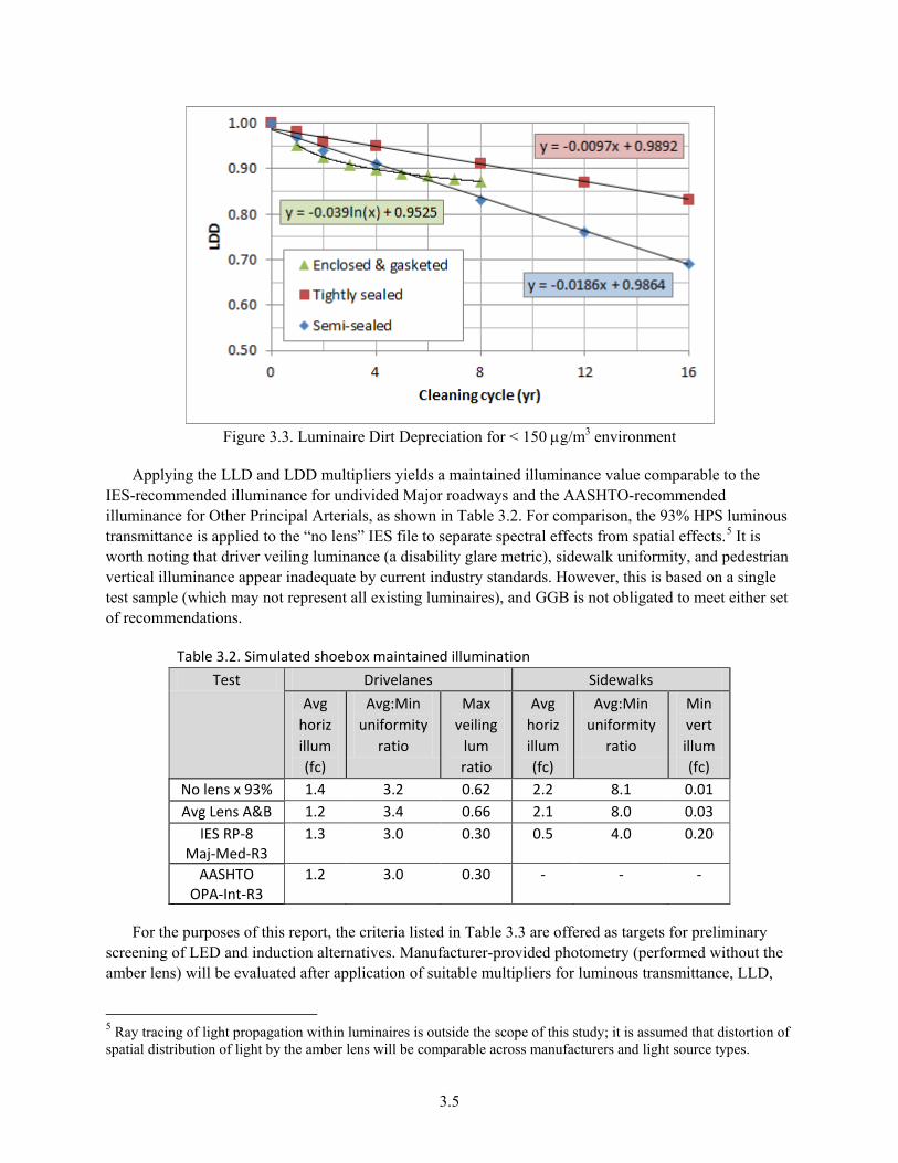
Luminaire dirt depreciation is a function of luminaire design, time between cleanings, and ambient particulate level. According to data published by the Environmental Protection Agency (EPA), concentrations of airborne particulate matter in San Francisco appear to be well below 150 µg/m3, indicating a “very clean” environment.4 Whereas an earlier models assumed linear degradation (IES 1971), current recommendations assume the effect is exponential (IES 2003); these estimates are illustrated in Figure 3.3. LDD is estimated at 91% prior to relamping, given a cleaning interval of three years, and assuming the luminaire can be accurately characterized as “enclosed and gasketed.”
3 The GGB standard 250 W HPS lamp is GE #85377 (rated 24,000+ hours). It is not clear whether newer alternatives such as Sylvania #67578 (rated 30,000 hours), non-cycling, or dual arc tube “standby” HPS would offer greater vibration resistance and service life. 4 Based on “coarse” particles between 2.5 and 10 µm in diameter (PM10) at site 060750005. Data is available online at http://www.epa.gov/airtrends/pm.html.
3.5
Figure 3.3. Luminaire Dirt Depreciation for < 150 µg/m3 environment
Applying the LLD and LDD multipliers yields a maintained illuminance value comparable to the IES-recommended illuminance for undivided Major roadways and the AASHTO-recommended illuminance for Other Principal Arterials, as shown in Table 3.2. For comparison, the 93% HPS luminous transmittance is applied to the “no lens” IES file to separate spectral effects from spatial effects.5 It is worth noting that driver veiling luminance (a disability glare metric), sidewalk uniformity, and pedestrian vertical illuminance appear inadequate by current industry standards. However, this is based on a single test sample (which may not represent all existing luminaires), and GGB is not obligated to meet either set of recommendations.
Table 3.2. Simulated shoebox maintained illumination Test Drivelanes Sidewalks
Avg horiz illum (fc)
Avg:Min uniformity
ratio
Max veiling
lum ratio
Avg horiz illum (fc)
Avg:Min uniformity
ratio
Min vert illum (fc)
No lens x 93% 1.4 3.2 0.62 2.2 8.1 0.01 Avg Lens A&B 1.2 3.4 0.66 2.1 8.0 0.03
IES RP-8 Maj-Med-R3
1.3 3.0 0.30 0.5 4.0 0.20
AASHTO OPA-Int-R3
1.2 3.0 0.30 - - -
For the purposes of this report, the criteria listed in Table 3.3 are offered as targets for preliminary screening of LED and induction alternatives. Manufacturer-provided photometry (performed without the amber lens) will be evaluated after application of suitable multipliers for luminous transmittance, LLD,
5 Ray tracing of light propagation within luminaires is outside the scope of this study; it is assumed that distortion of spatial distribution of light by the amber lens will be comparable across manufacturers and light source types.

3.6
and LDD. Note that the sidewalk appears to be overlit relative to IES recommendations; however, illumination here should remain comparable to the roadway illumination for monitoring purposes.
Table 3.3. Suggested criteria for maintained shoebox performance Application Metric Target
Drivelanes Avg horizontal illum (fc) ≥ 1.4
Avg:Min uniformity ratio ≤ 3.0 Veiling luminance ratio ≤ 0.6
Sidewalks Avg horizontal illum (fc) ≥ 1.4 Avg:Min uniformity ratio ≤ 6.0
Min vertical illum (fc) ≥ 0.02
With its release in July 2011, IES HB-10 introduced guidance for the use of scotopic/photopic (S/P) ratios to calculate mesopic multipliers for streets with a speed limit of 25 mph or less. Given the posted speed limit of 45 mph, only photopic quantities—rather than mesopic or scotopic—are applicable to roadway lighting on the bridge. Similarly, whereas improved uniformity can give LED products a competitive edge in parking lot applications (which use minimum illuminance as the criterion), improved uniformity is not necessarily of any benefit in roadway applications (which use average illuminance as the criterion). Hence, barring an improved utilization factor (percentage of luminaire output delivered to the roadway), LED luminaires must produce maintained output comparable to HPS. Assuming LED and induction luminaires would feature a service life greatly exceeding HPS, their LLDs and LDDs must likely be lower (harsher) than for HPS. Given the desire for energy savings, products drawing no more than 315 W of input power are targeted for this analysis.6
If no commercially-available LED or induction luminaire can be found which produces illumination equivalent to HPS in terms of quality and quantity, it is doubtful any commercially-available LED or induction retrofit kit would prove adequate, either. Luminaire manufacturers have the ability to integrate electrical, thermal, and optical components for optimal system performance. By contrast, commercially-available retrofit kits are generally designed for installation in a variety of housings, and thus are not optimized for any given housing. However, it may be possible to develop a custom retrofit kit which approaches or exceeds the performance of commercially-available luminaires in this particular application.
6 HPS lamp voltage and ballast input wattage vary with time but are expected to remain within ANSI tolerances (ANSLG 2009).

4.1
4.0 Shoebox Performance—Induction
Induction luminaire manufacturers were considered on the basis of IES-format photometric files being available for download from their websites (IES 2002).1 In addition, manufacturers with products eligible for incentives from BC Hydro as replacements for 250 W HPS luminaires were asked to provide this data if it was not available online.2 It was determined that some files by some manufacturers were identical to files by other manufacturers; in such cases only data by the manufacturer publishing more data online was used in the analysis. No verification testing of product samples was performed as part of this analysis.
Normalization of the IES files required an understanding of the lamps and ballasts used in each luminaire.3 Whereas cutsheets for luminaires utilizing QL or Sylvania lamps usually made this clear, cutsheets for other products generally did not specify the manufacturer of the lamp-ballast system. Table 4.0 provides an overview of lamp wattages and shapes considered. The Fulham lamp-ballast product line bears a striking resemblance to product lines offered by Global, Think, and others; however, performance claims vary between these manufacturers.
Table 4.0. Common induction lamp wattages Manufacturer (Min. CCT)
Shape/format Arbitrary/Globe Circle Rectangle
Fulham* (2700 K)
35, 55, 85, 100, 120, 165, 200, 250
40, 70, 80, 100, 120, 150, 200, 250,
300, 400
40, 70, 80, 100, 120, 150, 200, 250,
300, 400 QL**
(2700 K) 55, 85, 165 n/a n/a
Sylvania* (3500 K)
n/a 40 40, 70, 100, 150
* Values shown exclude ballast losses. ** Values shown are nominal—actual values are a function of nominal line voltage.
DSS output is a particularly useful metric for induction luminaires in this application since, due to lamp-reflector proximity, it is difficult to control the spatial distribution of light without incurring undesirable losses.4 Table 4.1 shows that of the induction luminaires considered, none appear likely to match initial HPS illumination while also providing energy savings. Of these manufacturers, only Kim and Visionaire offered IES files for distributions being asymmetric front-to-back at these wattages. The Deco luminaire incorporates two 150 W lamps. Although 1st Source does not offer IES files on their website, products by the company were already under consideration by GGB before PNNL became involved in the project, and IES files were provided upon request.
1 IES-format files are required to calculate uniformity and veiling luminance ratios, etc. Although some manufacturers may claim otherwise, such data is not proprietary in nature. 2 The website www.bchydro.com/ecatalog was accessed 2012-01-13. 3 IES files for induction luminaires are usually based on relative photometry, allowing adjustment of rated lamp lumens when using lighting software. The IES does not offer a recommended test method for induction luminaires. 4 Downward street-side lumens are calculated by summing lumens in LCS zones FL, FM, FH, and FVH.

4.2
Table 4.1. Initial luminaire performance characteristics excluding amber lens Product (Lamp) Lamp
output (lm)
Luminaire output
(lm)
DSS output
(lm)
Input power
(W)
DSS efficacy (lm/W)
Shoebox (HPS) without amber lens
28890 20493 12139 314 39
GE Lighting Solutions (Sylvania) MSCL-15T-4E21-GSC2
12000 10536 5237 156 34
Hubbell Kim (QL) 1A-AR3-165-IF-277
12000 5886 3828 165 23
Visionaire (QL) AME-2-I-T3-165G-IND-3K-4
12000 7015 4476 165 27
Philips Wide-Lite (QL) EALQL-165-5V-277
12000 8364 4188 165 25
Neptun 37250
20000 16717 7420 250 30
Everlast ESB-EC-250W-120-4000K
21000 14132 7056 265 27
1st Source (Sylvania) UISB-IT-2-150-150-35K-M4-2
24000 17130 8568 312 27
Deco (Sylvania) D828i-300-35-277
24000 15471 7728 312 25
Induction lamp-ballast systems are generally rated for 100,000 hours of service life, but published lumen maintenance data indicates 60,000 hours (60% of rated life) may be a better estimate for design purposes:
• QL only publishes LLD to 60,000 hours (78% LLD at that point) • Sylvania, Fulham, and Think are rated for 70% LLD at 60,000 hours • Documentation provided by Everlast indicates 78% LLD at 60,000 hours.
Assuming cleaning accompanies the replacement of components, LDD is estimated at 85%. For simplicity, luminous transmittance is somewhat liberally estimated at 91% regardless of CCT.
Table 4.2 shows that the higher luminous transmittance, LLD and LDD values for HPS only broaden the expected performance gap. Red text indicates values which miss the mark by more than 10%. Horizontal illuminance on the roadway is less than half the target for all luminaires, and uniformity is substantially worsened. The reduced disability glare is directly attributable to light being effectively contained to the areas around poles, leaving intermediate areas relatively dark. Consequently, it is deemed highly unlikely an induction retrofit kit could be developed which could maintain HPS illumination levels while also providing energy savings.
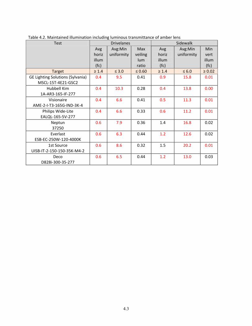
4.3
Table 4.2. Maintained illumination including luminous transmittance of amber lens Test Drivelanes Sidewalk
Avg horiz illum (fc)
Avg:Min uniformity
Max veiling
lum ratio
Avg horiz illum (fc)
Avg:Min uniformity
Min vert illum (fc)
Target ≥ 1.4 ≤ 3.0 ≤ 0.60 ≥ 1.4 ≤ 6.0 ≥ 0.02 GE Lighting Solutions (Sylvania)
MSCL-15T-4E21-GSC2 0.4 9.5 0.41 0.9 15.8 0.01
Hubbell Kim 1A-AR3-165-IF-277
0.4 10.3 0.28 0.4 13.8 0.00
Visionaire AME-2-I-T3-165G-IND-3K-4
0.4 6.6 0.41 0.5 11.3 0.01
Philips Wide-Lite EALQL-165-5V-277
0.4 6.6 0.33 0.6 11.2 0.01
Neptun 37250
0.6 7.9 0.36 1.4 16.8 0.02
Everlast ESB-EC-250W-120-4000K
0.6 6.3 0.44 1.2 12.6 0.02
1st Source UISB-IT-2-150-150-35K-M4-2
0.6 8.6 0.32 1.5 20.2 0.01
Deco D828i-300-35-277
0.6 6.5 0.44 1.2 13.0 0.03


5.1
5.0 Shoebox Performance—LED
Given the low sensitivity of its luminous transmittance to the SPD of the light source, preliminary screening of LED shoebox alternatives was performed without consideration of the amber lens. Candidate luminaire manufacturers were identified by searching the following product listings:
• LED Lighting Facts products listed under the “outdoor area/roadway” fixture type 1 • DesignLights Consortium (DLC) Qualified Products List (QPL) “outdoor pole/arm-mounted”
categories.2
Table 5.0 lists a number of manufacturers offering LED luminaires which—in this application— produce illumination comparable to HPS while requiring less input power.3 In an attempt to normalize the data, only luminaires featuring a nominal CCT below 5000 K (without amber lens) were considered, as the amber lens would be expected to decrease such CCTs to 3500 K or lower.
Table 5.0. Initial luminaire performance characteristics excluding amber lens Product CCT
(K) DSS
output (lm)
Input power
(W)
DSS efficacy (lm/W)
Shoebox (HPS) without amber lens
- 12139 314 39
Acuity Lithonia CSX2LED4-30B700-40K-SR3
4000 17393 294 59
Cooper McGraw-Edison VTS-C11-LED-E1-T3-7040
4000 13733 279 49
Cree BetaLED ARE-EDG-3M-16-D-UL-525-43K
4300 12207 256 48
GE Lighting Solutions ERS4-0-TX-CX-5-40
4000 15169 258 59
Leotek GC2-120E-MV-NW-3-GY-700
4300 12085 271 45
Philips Gardco RL-1-4V3-260LA-NW-UNIV
4000 14085 258 55
Philips Hadco RX2160-X-3-N-A-5-X-X-N
4000 12791 278 46
Philips Roadway RVM-270W160LED4K-LE3-277
4100 14255 271 53
Philips Wide-Lite ASA-128G1-700-NW-2L0-120
4125 16243 277 59
1 Accessed www.lightingfacts.com on 2012-04-24. 2 Accessed http://designlights.org on 2012-04-24. 3 Visionaire was in the process of updating their product and photometry at the time this report was published.

5.2
Of these manufacturers only Hadco published lumen output for a nominal CCT at or below 3000 K, indicating efficacy at 3000 K is 75% of the efficacy at 4000 K for this particular configuration (data for others is provided in Appendix I). The other manufacturers were asked whether CCTs at or below 3000 K were available (if this was not already indicated on product cutsheets) and, if so, what multiplier should be applied to accurately adjust available data for higher CCTs. Claimed multipliers varied widely among manufacturers, ranging from 63 to 85% of efficacy at the higher CCT, but were roughly centered around the Hadco multiplier. Lower values are reportedly due in part to the use of warm white LED packages designed for interior applications, where efficacy is compromised to some extent in the pursuit of higher CRI. Conversely, LED packages marketed as “outdoor white”—which usually target 4100 K—generally compromise CRI somewhat in order to increase efficacy. In other words, multipliers are generally lowest (greatest penalty) when CRI is higher at the lower CCT.
IES TM-21 (IES 2011b) offers two methods of determining LLD and LED lumen maintenance life: Either LLD is specified and extrapolation is used to determine LED lumen maintenance life, or LED lumen maintenance is specified and extrapolation is used to determine LLD. TM-21 also defines two different designations for characterization of LED lumen maintenance life, namely “Reported” or “Calculated” values, indicated in hours.4 Whereas Reported values must not exceed six times the IES LM-80 (IES 2008b) test duration,5 Calculated values are unrestricted and consequently may have little or no statistical basis.
IES HB-10 differs from TM-21 in its recommendation that LLD be no higher than 70% for LED products, based on the conservative assumption that these products will be allowed to operate until they have visibly diminished in output (IES 2011c). However, L70 values (hours of operation until output diminishes to 70% of initial) often greatly exceed the so-called “six times” limit prescribed by TM-21 for Reported lumen maintenance life. Thus, this approach effectively encourages manufacturers to emphasize the less substantiated Calculated values.
The TM-21 methodology allows for determination of unique LLD values for each LED product, rather than simply applying an assumed value of 70% to all products; this can potentially result in reduced LED quantity, product cost, and energy use. However, estimates based solely on LM-80 data are liberal when applied directly to luminaires, even when combined with In Situ Temperature Measurement Testing (ISTMT) data, since other unaccounted-for failure mechanisms may accelerate lumen depreciation (EPA 2010, NGLIA 2011).
For the purpose of this report, LED components are assumed to require replacement after approximately 50,000 hours of operation (over 12 years when operated 11 hours every night),6 accompanied by cleaning of the luminaire for an LDD of 87%. Implicit in this assumption is that the LED light sources will also be replaced at this time, to reduce labor costs and to ensure compatibility with the new drivers. It seems unlikely that the LED light sources would be allowed to continue operating until they visibly diminish in output, given that the currently high initial cost of LEDs is expected to continue to decrease over time. By the time a driver or another component fails, LEDs will likely be replaced proactively—just as HPS lamps are often replaced when their ballasts fail.
4 The term “Projected” is used interchangeably with the term “Calculated.” 5 Extrapolation is limited to 5.5 times the test duration if fewer than 20 samples are tested. 6 The DLC currently requires an L70 of 50,000 hours for associated product categories (“Outdoor Pole/Arm-Mounted Area and Roadway Luminaires”, and “Retrofit Kits for Outdoor Area and Roadway Luminaires”).

5.3
TM-21 calculations were performed using the ENERGY STAR TM-21 spreadsheet tool,7 based on nominal LED drive current, LM-80 reports, and ISTMT documentation provided by each manufacturer. For simplicity, ambient temperature effects were assumed negligible in terms of instantaneous and long-term performance. In addition, it was assumed that other variables such as bridge vibration will not compromise service life. Table 5.1 summarizes LLD values calculated per TM-21; following is a summary of adjustments and assumptions made while performing these calculations:
• Although LED Lighting Facts allows LM-80 drive current to differ by 5% from nominal (i.e., rated by luminaire manufacturer), for conservative calculation no such tolerance was used.8
• The ENERGY STAR calculator does not report values if one of the LM-80 lumen maintenance curves (at a given Ts and drive current) has positive slope; in such scenarios only the curve with negative slope was used.
• Time points within 50 hours (1% of 5,000 hours) of the last LM-80 measurement were adjusted slightly as needed to be considered by the ENERGY STAR calculator; for example, if the last measurement was after 6,048 hours of operation and a prior measurement had been performed after 1,008 hours of operation, these values were changed to 6,028 and 1,028 respectively.
• The LM-80 reports for the BetaLED and GE Lighting Solutions products included 6,048 hours of test data for 25 samples, with additional data to 10,080 hours of operation for 20 of these samples. The five samples not included in the 10,080 hour set were among the lowest six in terms of lumen maintenance at 6,048 hours. Values shown are based on the 20 samples operated 10,080 hours, yielding LLDs approximately 3-4% higher than LLDs based on 25 samples operated 6,048 hours.
7 Available for download at www.energystar.gov/TM-21calculator. 8 From the LED Lighting Facts Partner Participation Manual, Version 3.1, available at www.lightingfacts.com.

5.4
Table 5.1. Lamp lumen depreciation (LLD) estimates Product Nominal
LED drive current
(mA)
Ts from ISTMT
(°C)
LLD at 36,000 h
LLD at 50,000 h
*
Reported L80 (h)
Acuity Lithonia CSX2LED4-30B700-40K-SR3
700 83.0 0.95 0.93 > 60,000
Cooper McGraw-Edison VTS-C11-LED-E1-T3-7040
1000 76.0 0.99 0.97 > 54,000
Cree BetaLED ARE-EDG-3M-16-D-UL-525-43K
525 73.9 0.96 0.94 > 60,000
GE Lighting Solutions ERS4-0-TX-CX-5-40
525 74.0 0.96 0.94 > 60,000
Leotek GC2-120E-MV-NW-3-GY-700
700 72.2 0.72 (0.65) 25,000
Philips Gardco RL-1-4V3-260LA-NW-UNIV
530 66.0 0.91 (0.87) > 36,000
Philips Hadco RX2160-X-3-N-A-5-X-X-N
530 74.6 0.91 (0.88) >36,000
Philips Roadway RVM-270W160LED4K-LE3-277
530 88.4 0.85 0.80 50,000
Philips Wide-Lite ASA-128G1-700-NW-2L0-120
700 88.5 0.86 (0.80) >42,000
* LLD values at 50,000 h are shown in parentheses if the extrapolation exceeds TM-21 limits for Reported values.
The available data and calculation methods indicate most of these integrated luminaires will exhibit excellent lumen maintenance, with all but Leotek ranging from 85% to 99% of initial output after 36,000 hours of operation. This duration corresponds to 9 years of service when operated 11 hours every night, and also serves as the Reported extrapolation limit for some of the luminaires considered. Predicted and actual lumen maintenance can be expected to vary from luminaire to luminaire depending on product design. However, for the purpose of this report, a single LLD of 0.80 was artificially applied to all LED luminaires considered to simply strike a balance between the 0.70 LLD recommended in IES HB-10 and the generally higher LLDs calculated using IES TM-21. This value also roughly corresponds to the lowest estimated LLDs at 50,000 hours (excluding Leotek). Table 5.2 compares performance against the target criteria in this scenario, assuming 88% luminous transmittance for nominally 4000-4300 K LEDs. Red text indicates values which miss the mark by more than 10%.

5.5
Table 5.2. Maintained illumination including luminous transmittance of amber lens Product Drivelanes Sidewalk
Avg horiz illum (fc)
Avg:Min uniformity
Max veiling
lum ratio
Avg horiz illum (fc)
Avg:Min uniformity
Min vert illum (fc)
Target ≥ 1.4 ≤ 3.0 ≤ 0.60 ≥ 1.4 ≤ 6.0 ≥ 0.02 Acuity-Lithonia
CSX2LED4-30B700-40K-SR3 1.8 2.6 0.63 1.3 4.3 0.07
Cooper McGraw-Edison VTS-C11-LED-E1-T3-7040
1.4 2.1 0.57 1.5 2.6 0.06
Cree-BetaLED ARE-EDG-3M-16-D-UL-525-43K
1.3 3.3 0.40 1.1 3.6 0.05
GE Lighting Solutions ERS4-0-TX-CX-5-40
1.5 4.0 0.43 1.8 5.2 0.01
Philips-Gardco RL-1-4V3-260LA-NW-UNIV
1.4 4.9 0.55 1.5 6.3 0.01
Philips-Hadco RX2160-X-3-N-A-5-X-X-N
1.2 3.1 0.48 1.8 6.0 0.01
Philips Roadway RVM-270W160LED4K-LE3-277
1.4 2.9 0.42 1.9 6.0 0.02
Philips Wide-Lite ASA-128G1-700-NW-2L0-120
1.6 7.5 0.80 1.8 4.4 0.01
Several of the luminaires appear to satisfy or nearly satisfy all of the photometric targets; others might prove adequate depending on finalized GGB criteria and the planned maintenance program. Some of these manufacturers have expressed interest in developing a custom retrofit kit, but would require additional information and coordination before committing to the project. These results suggest it may be technically feasible to develop an LED retrofit kit which saves energy while matching HPS light levels.
Another item not yet considered is the thermal management limitations imposed by the existing HPS shoebox housings, which—unlike many LED luminaire housings—are neither ventilated nor finned for passive heat dissipation. The existing shoebox housing weighs approximately 85 pounds (excluding remote ballast) and measures approximately 26" wide by 39" long by 12" tall (excluding the protruding amber lens).9 By comparison, the Lithonia LED luminaire shown in Figure 5.0 is rated to weigh 59 pounds (driver included) and measure less than 19" wide by 36" long by 6" tall. The larger form factor of the existing housing suggests it could enable adequate heat dissipation, depending on its material content and thermal characteristics.
9 The weight of internal components which would be removed during a retrofit has not yet been determined.

5.6
Figure 5.0. Lithonia LED luminaire without visible heat fins
Once it is confirmed a given retrofit kit—presumably somewhat smaller than a complete luminaire—would physically fit in the existing housing, the following tests should be performed with the product installed in the existing housing (in situ) and enclosed by the amber lens:
• IES LM-79, to verify initial performance parameters such as lumen output, input power, color characteristics, and spatial distribution of light (IES 2008a).
• ISTMT, to enable estimation of long-term performance by capturing actual LED operating temperature.
This methodology is used by the DLC to ensure retrofit kit performance is not overstated by manufacturers, as described in Appendix H. Perhaps due to such thermal management limitations, only two retrofit kits on the DLC QPL were listed for more than 12,000 lm of total output.
• A 4500 K product offered by Noribachi (Qnuru) was listed at 16,400 lm and 250 W. • A 4900 K retrofit kit offered by Xeralux was listed at 12,300 lm and 168 W.
No photometry or cutsheet was available on the Noribachi website, but an LM-79 report and IES file were provided upon request. This product was only offered in an axially symmetric (Type VS) distribution, which would broadcast excessive illumination behind the luminaire, yielding an initial DSS efficacy of just 33 lm/W (comparable to the induction luminaires). Uniformity would also be poor.
Xeralux was one of a handful of LED manufacturers already under consideration by GGB prior to DOE involvement in the project. Photometry was available online, and according to the cutsheet the DLC-approved product was the highest-output version offered. In addition to data for this standard product (intended for broad application), Xeralux provided PNNL with photometry for a custom LED module which had been designed specifically for the bridge. Although both products were tested in shoebox housings to roughly capture thermal effects, they have not yet been tested in one of the existing housings with amber lens. Table 5.3 summarizes lumen maintenance characteristics of the 4000 K version of the standard DLC-listed product, and Table 5.4 gives an estimate of maintained light levels, again applying 0.80 LLD (consistent with the LED luminaires). Red text indicates values which miss the mark by more than 10%.

5.7
Table 5.3. Lamp lumen depreciation (LLD) estimate for 4000 K version of standard Xeralux kit Product Nominal
LED drive current
(mA)
Ts from ISTMT
(°C)
LLD at 36,000 h
LLD at 50,000 h
*
Reported L80 (h)
Xeralux XLE-L2S-418-40P7
700 64.8 92 (90) > 36,000
* LLD values at 50,000 h are shown in parentheses if the extrapolation exceeds TM-21 limits for Reported values (provided in the next column).
Table 5.4. Maintained illumination including luminous transmittance of amber lens
Product Drivelanes Sidewalk Avg
horiz illum (fc)
Avg:Min uniformity
Max veiling
lum ratio
Avg horiz illum (fc)
Avg:Min uniformity
Min vert illum (fc)
Target ≥ 1.4 ≤ 3.0 ≤ 0.60 ≥ 1.4 ≤ 6.0 ≥ 0.02 Xeralux
XLE-L2S-418-40P7 0.8 5.1 0.51 1.3 12.2 0.00
The standard Xeralux retrofit kit would fall well short of the target light levels while also compromising uniformity. Table 5.5 summarizes the anticipated effect of the amber lens on color characteristics for the module developed by Xeralux specifically for the bridge. This product was designed to eliminate any greenish hue, and the results suggest careful mixing of differently-colored LEDs can indeed improve Duv in this manner. In addition, QGG would be compromised but still acceptable. However, Xeralux estimates the existing shoebox housings could accommodate no more than four of the 40.5 W modules. Consequently, initial illuminance would be reduced by at least 38% relative to the already inadequate standard retrofit kit, greatly outweighing any improvement in luminous transmittance of the amber lens. LM-80 data was not available for the differently-colored LEDs used in the mix.
Table 5.5. Effect of amber lens on color characteristics for custom Xeralux module Product Lens CCT (K) Duv CRI R9 RGG QGG
Xeralux
Neutral 1819 -0.002 70 -7 44 82 Amber 1730 0.005 67 -15 38 46
Although no suitable commercially-available LED product was identified, it appears feasible to develop an LED retrofit kit which would save energy while maintaining HPS light levels. However, the following issues will present challenges for manufacturers of custom retrofit kits and will require substantial coordination with the GGB project team:
• A carefully selected mixture of differently-colored LEDs may be required to avoid a greenish hue when operated behind the amber lens
• Since different types of LEDs may degrade at different rates, products incorporating more than one type of LED may require specialized electronics to prevent color shift over time

5.8
• Retrofit kits must be tested in situ (in the existing shoebox housing) to capture thermal effects on photometry, colorimetry, and ISTMT
• Retrofit kits must be securely mounted in the existing housing and demonstrate adequate resistance to vibration
• The added weight of retrofit kits must be determined and approved by GGB to ensure the existing poles are not overloaded.

6.1
6.0 Shoebox Performance—Other Technologies
In addition to LED and induction, two high-intensity discharge (HID) light source technologies also merit discussion due to their compactness (enabling optical control) and high lamp-ballast efficacies:
• Next-generation ceramic metal halide (CMH) lamps optimized for use with electronic ballasts, often referred to as eHID. A number of major manufacturers offer eHID lamp-ballast systems, e.g., the Philips Elite product family, which is offered in CCTs of 3000 or 4200 K at lamp wattages of 210 and 315 W.1
• An electrodeless HID technology commonly denoted plasma. Luxim and Topanga are the only known manufacturers of plasma lamp-ballast systems.2 As of May 2012, Luxim did not offer a nominal CCT below 5200 K, and although Topanga offered 4000 K this light source was not yet offered in any commercially available roadway luminaire.
Table 6.0 below summarizes performance for commercially available luminaires incorporating a 210 W Elite lamp, which features luminaire input power of 227 W—lower than any of the LED products considered. Red text indicates values which miss the mark by more than 10%. Ballast input power is rated at 341 W for the higher output version of the lamp and thus would not represent an energy saving alternative to the existing HPS lamp-ballast system, which was measured at 317 W. Assuming that—as with HPS—lamps would fail at 50% of rated life, LLD is estimated at 85% after 14,000 hours of operation (just over three years) and LDD is estimated at 90%. At 3000 K, luminous transmittance of the amber lens would be approximately 90%.
Table 6.0. Maintained illumination including luminous transmittance of amber lens Product Drivelanes Sidewalk
Avg horiz illum (fc)
Avg:Min uniformity
Max veiling
lum ratio
Avg horiz illum (fc)
Avg:Min uniformity
Min vert illum (fc)
Target ≥ 1.4 ≤ 3.0 ≤ 0.60 ≥ 1.4 ≤ 6.0 ≥ 0.02 Acuity-AEL *
125-21-MC-ELBD-277-R2-FG 1.1 3.0 0.61 1.9 7.1 0.01
Hubbell-Kim 1SA-WP9LE3-210CMH-277
1.5 2.8 0.39 1.4 3.6 0.01
Philips-Gardco EH19-1-3-210MCE-3K-QUAD
1.1 2.7 0.47 1.4 7.5 0.01
Philips Wide-Lite OPP-210-A-277E-Sx
0.8 3.3 0.41 0.4 2.3 0.02
* A 315 W IES file was scaled by PNNL to approximate 210 W performance.
Although the expected service life would not be appreciably greater than the existing HPS, the rated performance of the Elite lamp in the Kim luminaire suggests this configuration (not yet catalogued) 1 For reference, the City of Chicago began installing luminaires utilizing the Elite and related Cosmopolis lamp-ballast systems in late 2011. 2 The terms “plasma” and “solid-state” are used in marketing material by both companies. Note that “plasma” is actually applicable to any gas-discharge source (such as fluorescent), and “solid-state” is actually applicable to any electronic ballast.

6.2
merits consideration; Kim has expressed interest in developing a custom induction retrofit kit for this project. However, similar to white LED and induction, the amber lens may render CMH lamps somewhat greenish in appearance by increasing Duv outside ANSI tolerances; Table 6.1 summarizes color characteristics based on data provided by Philips.
Table 6.1. Effect of amber lens on color characteristics for CMH Product Lens CCT (K) Duv CRI R9 RGG QGG
Philips MasterColor CDM-T Elite 210W/930
neutral 2911 -0.004 92 74 99 98 amber 2471 0.012 89 47 85 78

7.1
7.0 Cobrahead Alternatives
The first 10 cobraheads south of the bridge are evenly spaced at approximately 160' along the road, and the cross-section here is essentially identical to the center of the bridge, with a span of approximately 88' between poles. By contrast, heading south from this 2x5 array of poles the roadway rapidly widens to 14 lanes—a span of approximately 213' between poles—and pole spacing along either side of the road is reduced to as little as 80' in places, as shown in Figure 7.0. These six luminaires just north of the tollbooths, which would merit different treatment in terms of criteria for spatial distribution of light, are considered outside the scope of this analysis since they do not cast light on any of the specially painted bridge surfaces. Luminaires are approximately 35'-6" above pavement on mast arms 6' to 8' in length; input power is rated at 305 W (less than for the shoeboxes) and wiring is 277 V.
Figure 7.0. Cobraheads just north of the tollbooths (Photo credit: Google)
Table 7.0 summarizes estimated maintained performance for the HPS cobraheads, using an IES file obtained from the manufacturer website and the measured output of the lamp sample which was used to test the shoebox. No amber lens is used for these luminaires; LLD and LDD are assumed equal to the shoebox values. Unfortunately, uplight cannot be evaluated since the manufacturer did not measure intensity at angles above horizontal.
Table 7.0. Estimated maintained illumination produced by existing HPS cobraheads Product Drivelanes Sidewalk
Avg horiz illum (fc)
Avg:Min uniformity
Max veiling
lum ratio
Avg horiz illum (fc)
Avg:Min uniformity
Min vert illum (fc)
GE Lighting Solutions M2AR-25S-0A1-GMS2-2
2.0 1.6 0.33 1.6 2.2 0.25
Note that illumination appears to be better under the cobraheads than under the shoeboxes in every aspect but horizontal illuminance on the sidewalks, which is still comparable to the roadway illumination and adequate per IES. It is not clear whether this discrepancy is accidental (merely attributable to use of the same lamp in a more cost-effective luminaire) or deemed necessary for transitional lighting to and

7.2
from the bridge. Consistent with section 4.7 of IES RP-8, it is assumed that transitional lighting is not necessary in this application; consequently, the less stringent shoebox criteria are considered adequate for cobrahead replacements. It is not clear whether historical status is strictly applicable to these luminaires; PNNL was directed by GGB to restrict the product search to those luminaires resembling HID cobraheads in terms of daytime appearance. Products were further filtered on the basis of availability in a nominal CCT below 3500 K, as shown in Table 7.1.
Table 7.1. HPS cobrahead alternatives Manufacturer (light source)
Appearance < 3500 K available?
Acuity-AEL (Philips Elite eHID)
(3000 K)
Cooper-Lumark (LED)
(3000 K)
Cree-BetaLED (LED)
GE Lighting Solutions (LED)
GE Lighting Solutions (QL induction)
(2700 or 3000 K)
Leotek (LED)
Philips-Hadco (LED)
(3000 K)

7.3
Note that whereas the LED alternatives would produce no direct uplight, the existing HPS luminaires and the eHID and induction alternatives emit some light upward due to the protruding lens. Table 7.2 summarizes maintained performance for commercially available cobrahead-style luminaires utilizing induction, LED, and eHID light sources. Red text indicates values which miss the mark by more than 10%. The same LLD and LDD values were applied here as in preceding sections of this report.
Table 7.2. Estimated maintained illumination for HPS cobrahead alternatives Product (source)
Drivelanes Sidewalk Avg
horiz illum (fc)
Avg:Min uniformity
Max veiling
lum ratio
Avg horiz illum (fc)
Avg:Min uniformity
Min vert illum (fc)
Target ≥ 1.4 ≤ 3.0 ≤ 0.60 ≥ 1.4 ≤ 6.0 ≥ 0.02 Acuity-AEL
125-21-MC-ELBD-277-R2-DG (CMH 3000 K)
1.6 2.5 0.26 1.3 3.2 0.08
Cooper-Lumark* LDRL-T3S-B06-E-8030
(LED 3000 K)
1.1 2.0 0.22 0.6 1.8 0.03
GE Lighting Solutions MSRL-64Q-4EX1-RSS3
(induction 3000 K)
0.5 3.2 0.22 0.4 3.2 0.03
Philips-Hadco RX2160-X-3-W-A-5-X-X-N
(LED 3000 K)
1.0 2.0 0.18 1.0 2.8 0.04
* IES file for 4000 K was scaled by 0.63 per manufacturer to approximate 3000 K performance.
It is assumed that, given the relatively low initial cost of HPS cobraheads, complete luminaire replacements will be preferable to retrofit kits. Induction does not perform as well in this application due to the lower luminaire efficiency, and LED performance is greatly compromised by the criterion of less than 3500 K for nominal CCT.
Although the 227 W eHID product from Acuity-AEL may not represent a desirable long-term alternative to the existing HPS cobraheads due to the comparable expected life, this luminaire offers energy savings and a simple means of exploring the acceptability of ∼3000 K light sources on the bridge. If this option is pursued, lamps should be seasoned in situ (operated in luminaires which are oriented as they will be installed) for 100 hours prior to visual evaluation. Given the high profile of the bridge and associated public scrutiny, bench-top or off-site seasoning would be preferable to on-site seasoning.

8.1
8.0 Experimenting with CCT
If the HPS floodlights and LPS post-tops were retrofitted to yield 3000 K output, this would enable retrofitting of the amber-lensed shoeboxes with 4200 K LED light sources. Higher efficacy would be achieved than for LEDs at 3000 K, and the amber lens would yield roughly 3200 K with minimal impact on lumen output. Further, the replacement of HPS and LPS with such warm-white broad spectrum sources would be expected to result in improved color rendition of the bridge paint. However, the acceptability of 3000 K illumination should be confirmed via careful mock-ups before committing to any large-scale retrofit project. In addition, it is likely that many off-the-shelf white light sources will yield some degree of greenish hue after being filtered by the amber lens; this could be resolved by tuning the SPD—possibly by mixing LEDs of different colors—or by replacing the existing lenses with a similar material which does not cause this green shift.
Assuming an efficiency of approximately 60-70% for the tower floodlights, the rated 51,000 lumens (51,000 lm) of the 400 W HPS lamps would translate to an initial luminaire output of roughly 30,000-36,000 lm for approximately 465 W of input power. This appears to be beyond the reach of commercially available floodlights and retrofit kits below 3500 K, regardless of the light source used—LED, induction, or eHID. However, a variety of HID alternatives merit consideration as direct replacements for the existing HPS lamps. By allowing the HPS ballast to remain, such products present an opportunity for relatively simple and inexpensive exploration of higher CCTs and the possible benefits of broad spectrum illumination—likely without any compromise to the spatial distribution of light.
It appears CMH replacements would be preferable to color-enhanced super HPS due to differences in lumen output and rated life, as shown in Table 8.0. Further, the greater maximum overall length (MOL) and light center length (LCL) may cause the super HPS lamp to be misaligned relative to the optical system or to simply not fit in the luminaire. The rated life of the CMH lamp is slightly lower than standard HPS, but it is not clear which would fare better in this reportedly high-vibration application. Possibly of greater significance is the reduction in lumen output relative to standard HPS, but this may be mitigated by the improved color rendition (CSJ 2010, CSJ 2011). Further, unlike illumination of the road and sidewalks, a slight reduction in tower illumination would be unlikely to pose a safety issue. If reduced output is then deemed acceptable, other lower-output HID or LED alternatives might be considered.
In any case, HID lamps should be allowed to operate in situ for 100 hours (10 days if operated 10 hours each day) to ensure they have stabilized before their color characteristics or light output are evaluated. Existing lamp orientation must also be determined to ensure compatibility of proposed alternatives; for example, a number of high-wattage CMH lamps are only rated for operation in a base-up (axis vertical) position. Lenses which have yellowed over time should also be replaced with newer lenses to allow for direct comparison of lamp CCTs.

8.2
Table 8.0. Comparison of standard HPS and alternative HID lamps for floodlights1 Parameter GE
# 85379 (standard HPS)
EYE # 67365
(super HPS)
GE # 93295 (CMH)
Philips # 130948 (CMH)
CCT (K) 2100 2500 3000 2 4000 CRI 22 85 80 80
Mean output (lm) 45,000 22,000 31,000 29,000 Life (h) 24,000+ 9,000 20,000 20,000
Bulb shape ED18 T15 ED18 ED18 MOL (in) 9.7500 11.1875 9.7500 9.7500 LCL (in) 5.7500 6.7188 5.7500 5.7500
It is doubtful any currently available lamp-ballast replacement could match the initial LPS lamp-ballast efficacy of over 140 lm/W. Assuming an efficiency of 50% and one 35 W LPS lamp rated 7800 lm per dual-lensed luminaire, initial post-top output is estimated at 3900 lm for approximately 54 W of input power. A custom LED or induction solution may merit consideration since, as with the floodlights, it may be determined that improved color rendition allows for some reduction in output. However, sidewalk illumination must be preserved. In addition, coordination with manufacturers would be required to address spatial restrictions and the thermal environment in the existing housings. Resistance to bridge vibration would also need to be reviewed.
1 All lamps are universal-burn with clear envelope and mogul base. Comparable alternatives to these products may be offered by other manufacturers such as Sylvania, Venture, etc. Note that basis for calculation of mean lumens and lifetime can vary somewhat from manufacturer to manufacturer. 2 The CCT of this CMH lamp is a function of operating position: 3000 K if lamp axis is oriented horizontally and 3600 K if vertical.

9.1
9.0 Conclusions
The historic status and high efficacy of the existing HPS and LPS luminaires present challenges for any energy-saving alternatives. In addition, the already-accepted color characteristics of these limited-spectrum light sources further limit the breadth and efficacy of suitable alternatives. Four luminaire types are currently used to illuminate the roadway, the two walkways, and the two towers; the CCTs of these luminaires range from approximately 1800 to 2100 K. By contrast, most white light alternatives (including LED, induction, and CMH) are offered in nominal CCTs of 2700 K or higher. Although the efficacy of other technologies is not strongly tied to CCT, the efficacy of pcLED products generally diminishes substantially at CCTs below 4000 K. All of the white light sources considered are expected to improve color rendition of the special bridge paint, but preliminary analysis suggests many of these sources may appear somewhat greenish in hue when installed in the amber-lensed shoebox luminaires.
Viability of the various technologies can be summarized as follows: • Due to its relatively limited efficacy once integrated into luminaires, induction does not
appear to be a viable alternative for the HPS shoeboxes, cobraheads, or floodlights. This technology may, however, merit consideration in the post-top LPS luminaires if sidewalk illumination is not overly compromised.
• LED technologies may merit consideration in the shoeboxes and the post-tops, offering approximately 6-18% energy savings for the former. Few luminaires resemble the daytime appearance of cobraheads, and efficacy at 3000 K is currently inferior to HPS. The substantial size and limited lumen packages of currently-available products further reduces the viability of LEDs as an alternative for the floodlights. However, LED may ultimately prove viable for all four luminaire types as technologies continue to improve.
• Although it would likely increase maintenance costs somewhat, CMH merits consideration as an energy-saving alternative for the cobraheads, and may also merit consideration for the shoeboxes—offering approximately 28% energy savings in either case. It also offers a relatively inexpensive means of evaluating higher CCT in the floodlights, and its improved color may demonstrate the acceptability of reduced tower illumination.
It is assumed that existing light levels must be preserved. A new analysis would need to be performed if the GGB ultimately determines reduced illumination would be acceptable. For example, if a product which reduces existing light levels by over 50% is deemed adequate, LED products matching this reduced illumination should be sought. This would enable the use of lower wattage products, thereby increasing energy savings and improving the feasibility of LED technology in this application.
It is similarly assumed that all four luminaire types should remain comparable in CCT, and that the allowable CCT range should remain centered at a fairly low value—probably no higher than 3000 K. CCT should be supplemented by other metrics (e.g., Duv and QGG) since it does not capture all color characteristics. Although the various metrics and criteria can help in preliminary product screening and selection, it is well established that lighting systems cannot be truly optimized using numerical methods alone. Final product selection should be preceded by physical mock-ups, as there is no substitute for visual evaluation. In addition, given that color preference is highly subjective and varies from individual to individual, all key stakeholders should be given an opportunity to voice opinions.

9.2
Based on the findings of this preliminary analysis, it is suggested that GGB begin with relatively straightforward and inexpensive replacements of HPS lamps and luminaires to explore the acceptability of CCTs higher than currently used on the bridge. The goal of these mock-ups is not to verify a color match with the remaining 1800 to 2100 K luminaires on the bridge, but rather to ascertain whether the bridge paint would retain an acceptably warm appearance if all four luminaire types were changed to approximately 3000 K. The following approaches balance associated costs and benefits:
1. Merely relamp all six floodlights up-lighting one side of a tower (as indicated in Figure 9.0) with the 3000 K CMH lamp from GE identified in Table 8.0. This retrofit would be relatively inexpensive but very high profile. Note that the remaining LPS post-tops at the base of the tower will be expected to visibly differ in color during this temporary evaluation.
2. Completely replace most or all of the 10 cobraheads at the south end of the bridge with the 3000 K CMH luminaire from Acuity-AEL identified in Table 7.2. This retrofit would be somewhat more costly but relatively low profile in comparison with the floodlights.
Figure 9.0. One of four possible sets of six floodlights to relamp with CMH
(adapted from Google photography)
These mock-ups would either result in approval or rejection of 3000 K as the new target CCT for the four luminaire types. If 3000 K is not deemed acceptable, it is unlikely that LED products of 4000 to 4300 K—approximately 3100 to 3300 K after filtering through the amber lens—would be appropriate for the shoeboxes. In this possible scenario, it might eventually be determined that light sources installed in the shoeboxes can be no higher than perhaps 2700 K; the CCT produced after filtering by the amber lens would then be at or below approximately 2400 K—quite close to the current range of 1800 to 2100 K. This would effectively preclude the use of currently available LED products, since their efficacy is significantly diminished at CCTs below 4000 K. A restriction of 2700 K would also limit options for other technologies; for example, the Philips CDM product is not currently offered in a nominal CCT below 3000 K.
If instead 3000 K is accepted (or even preferred), retrofit kits for the shoeboxes and post-top luminaires might be developed to produce a cohesive appearance across all four luminaire types. Although it may seem obvious, it bears mentioning that it would not be difficult to produce retrofit kits which reduce input power while also reducing light output; this could be achieved most cost-effectively by simply replacing existing lamp-ballast systems with lower-wattage versions (i.e., still HPS or LPS).

9.3
This illustrates the importance of developing a set of specifications to guide manufacturers and to enable apples-to-apples comparison of alternatives.
A model specification was recently developed by the DOE Municipal Solid-State Street Lighting Consortium to serve as a template, and PNNL could assist the GGB in tailoring this document to meet the particular needs of this project.1 Items which should be addressed in a specification and coordinated with manufacturers include:
• Photometric and colorimetric criteria such as those utilized in this assessment. Retrofit kits should be tested (LM-79 and ISTMT) in an existing amber-lensed shoebox to accurately capture thermal effects, spectral effects, and the impact on spatial distribution of light.
• Warranty requirements and criteria for maintained performance over time. • Criteria for electrical immunity and interference. • Criteria for testing to demonstrate resistance to bridge vibration. • Criteria for resistance to the elements in this coastal environment. • The loading capacity of the poles—the weight of existing components to be removed and the
weight of retrofit kits must both be ascertained. • Precise space constraints and other mechanical compatibility considerations.
The GGB will need to determine whether an open RFP should be issued using such a specification, or if it would be preferable to instead begin by coordinating with a small set of preferred manufacturers such as those identified in this assessment. Following is a summary of the manufacturers not already in contact with GGB which—based on the screening process implemented for this assessment—currently appear best suited to developing retrofit kits for the amber-lensed shoeboxes or complete replacements for the cobraheads:
• Acuity-AEL, www.americanelectriclighting.com (CMH cobrahead) • Acuity-Lithonia, www.lithonia.com (LED shoebox) • Cooper-McGraw, www.cooperindustries.com/content/public/en/lighting/brands/mcgraw-
edison.html (LED shoebox) • Cree-BetaLED, www.betaled.com (LED shoebox) • Hubbell-Kim, www.kimlighting.com, (CMH shoebox) • Philips Roadway, www.usa.lighting.philips.com/us_en/subsites/roadway (LED shoebox).
Of the luminaire manufacturers listed above for shoebox alternatives, none are accustomed to developing custom retrofit kits, but indicated interest due to the unusually high profile of this project. This interest may diminish as more information is gleaned through coordination with GGB staff, and in time these and other manufacturers will likely develop products superior to those evaluated in this assessment. For these reasons, the manufacturers identified in this assessment are merely offered for reference—providing a realistic sense of current technological capabilities—and as a suggested starting point.
Although no suitable commercially-available LED product was identified, it appears feasible to develop an LED retrofit kit which would save energy while maintaining HPS light levels. However, the
1 The model specification can be downloaded at www.ssl.energy.gov/specification.html. Of the two versions posted online, the “System” version is recommended to more directly address illuminance levels, uniformity, etc.

9.4
following issues will present challenges for manufacturers of custom retrofit kits and will require substantial coordination with the GGB project team:
• A carefully selected mixture of differently-colored LEDs may be required to avoid a greenish hue when operated behind the amber lens
• Since different types of LEDs may degrade at different rates, products incorporating more than one type of LED may require specialized electronics to prevent color shift over time
• Retrofit kits must be tested in situ (in the existing shoebox housing) to capture thermal effects on photometry, colorimetry, and ISTMT
• Retrofit kits must be securely mounted in the existing housing and demonstrate adequate resistance to vibration
• The added weight of retrofit kits must be determined and approved by GGB to ensure the existing poles are not overloaded.
There does not yet appear to be a simple means of reducing energy use and maintenance while preserving the quality and quantity of illumination for this historic landmark. Although LED technologies are expected to become increasingly viable over time, and product mock-ups may reveal near-term solutions, some options not currently considered by GGB may ultimately merit evaluation. For example, it would be preferable in terms of performance to simply replace existing luminaires (some of which may already be nearing end of life) with fully-integrated LED or CMH luminaires rather than replacing internal components. Among other benefits, this would allow reputable manufacturers to offer standard warranties for their products. Similarly, the amber lenses might be reformulated such that they do not render white light sources in a greenish cast, thereby allowing the use of off-the-shelf LED or CMH products. It also bears repeating that the amber-lensed shoeboxes bear no resemblance to the LPS luminaires originally used to light the roadway.

10.1
10.0 References
ANSI 2011. ANSI C136 Committee. ANSI C136.37-2011, “American National Standard for Roadway and Area Lighting Equipment – Solid State Light Sources Used in Roadway and Area Lighting.” National Electrical Manufacturers Association, Rosslyn, VA. ANSLG 2008. American National Standard Lighting Group. ANSI_NEMA_ANSLG C78.377-2008, “American National Standard for Electric Lamps – Specifications for the Chromaticity of Solid State Lighting (SSL) Products.” National Electrical Manufacturers Association, Rosslyn, VA. ANSLG 2009. American National Standard Lighting Group. ANSI_ANSLG C78.42-2009, “American National Standard for Electric Lamps: High-Pressure Sodium Lamps.” National Electrical Manufacturers Association, Rosslyn, VA. CIE 1995. CIE Division 1, Vision and Colour. CIE 13.3-1995, “Technical Report: Method of Measuring and Specifying Colour Rendering Properties of Light Sources.” International Commission on Illumination, Vienna, Austria. CSJ 2010. Mutmansky, M., et al. “Advanced Street Lighting Technologies Assessment Project – City of San Jose.” San Jose, CA. CSJ 2011. City of San Jose. “Public Streetlight Design Guide.” San Jose, CA. DOE 2011. Bardsley Consulting, et al. “Solid-State Lighting Research and Development: Multi-Year Program Plan.” March 2011. Lighting Research and Development, Building Technologies Program, Office of Energy Efficiency & Renewable Energy. U.S. Department of Energy, Washington, D.C. EPA 2010. ENERGY STAR Manufacturer’s Guide for Qualifying Solid State Lighting Luminaires – Version 2.1. April 2010. Office of Air and Radiation. U.S. Environmental Protection Agency, Washington, DC. GGB 1935. Morrow, I.F. “Report on Color and Lighting for the Golden Gate Bridge, San Francisco.” Golden Gate Bridge Highway & Transportation District, San Francisco, CA. IDOT 2002. Dunker, K.F. et al. “Report on Vibration Monitoring of Luminaires on the Burlington Cable-Stayed Bridge.” Iowa Department of Transportation, Ames, IA. IES 1971. Van Dusen, H. A. Jr. “Maintenance and Adjustment Factors in Street Lighting Design Calculations.” Journal of the Illuminating Engineering Society, October 1971, p. 62. Illuminating Engineering Society of North America, New York, NY. IES 1999. IESNA Testing Procedures Committee, Subcommittee on Photometry of Light Sources. IESNA LM-54-99, “IESNA Guide to Lamp Seasoning.” Illuminating Engineering Society of North America, New York, NY. IES 2000. IESNA Roadway Lighting Committee, Standard Practice Subcommittee. ANSI / IESNA RP-8-00, “American National Standard Practice for Roadway Lighting.” Illuminating Engineering Society of North America, New York, NY.

10.2
IES 2002. IESNA Computer Committee, Subcommittee on Photometry. ANSI/IESNA LM-63-02, “IESNA Standard File Format for the Electronic Transfer of Photometric Data and Related Information.” Illuminating Engineering Society of North America, New York, NY. IES 2003. IESNA Roadway Lighting Committee, Subcommittee on Lighting Maintenance & Light Sources. IESNA DG-4-03, “Design Guide for Roadway Lighting Maintenance.” Illuminating Engineering Society of North America, New York, NY. IES 2008a. IES Testing Procedures Committee, Subcommittee on Solid-State Lighting. IES LM-79-08, “Approved Method: Electrical and Photometric Measurements of Solid-State Lighting Products.” Illuminating Engineering Society of North America, New York, NY. IES 2008b. IES Testing Procedures Committee, Subcommittee on Solid-State Lighting. IES LM-80-08, “IES Approved Method for Measuring Lumen Maintenance of LED Light Sources.” Illuminating Engineering Society of North America, New York, NY. IES 2011a. IES Luminaire Classification Task Group. IES TM-15-11, “Luminaire Classification System for Outdoor Luminaires.” Illuminating Engineering Society of North America, New York, NY. IES 2011b. IES Testing Procedures Committee, Subcommittee on Solid-State Lighting. IES TM-21-11, “Projecting Long Term Lumen Maintenance of LED Light Sources.” Illuminating Engineering Society of North America, New York, NY. IES 2011c. DiLaura et al. IES HB-10-11, “The Lighting Handbook, Tenth Edition, Reference and Application.” Illuminating Engineering Society of North America, New York, NY. NGLIA 2011. “LED Luminaire Lifetime: Recommendations for Testing and Reporting,” Second Edition, June 2011. U.S. Department of Energy, Washington, D.C. NIST 2010. Davis, W., and Ohno, Y. “Color quality scale.” Optical Engineering, Vol. 49(3), 033602-1, March 2010.

A.1
Appendix A
Excerpts from the GGB Online Research Library

A.2

A.3

A.4

A.5

A.6

Appendix B
Paint Sample Test Data


B.1

B.2

B.3

B.4

Appendix C
Amber Lens Specification


C.1


Appendix D
HPS Shoebox Test Data—Lens A


D.1

D.2

D.3

D.4

D.5

D.6

Appendix E
HPS Shoebox Test Data—Lens B

E.2

E.3

E.4

E.5

E.6

E.7


Appendix F
HPS Shoebox Test Data—No Lens

F.2

F.3

F.4

F.5

F.6

F.7


Appendix G
HPS Shoebox Test Data—Bare Lamp

G.2

G.3
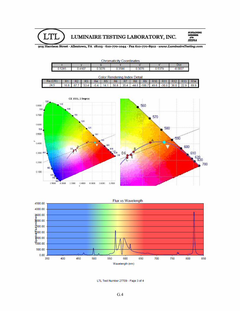
G.4

G.5


Appendix H
Excerpts from PG&E and DLC QPL Websites

H.2

H.3

H.4

H.5


Appendix I
Sample LED Efficacies at 3000 and 4000 K
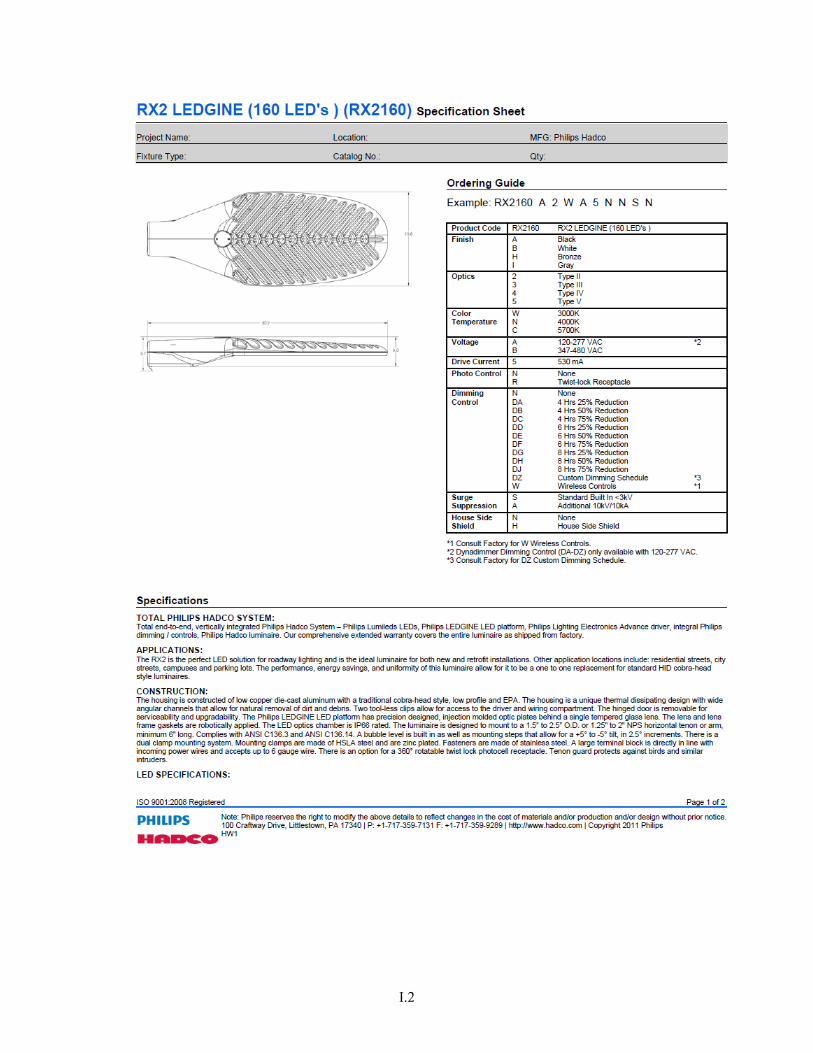
I.2

I.3

I.4


BUILDING TECHNOLOGIES PROGRAM