Technical documentation MGK-2 gas condensing...
12
Technical documentation MGK-2 gas condensing boiler MGK-2 - 130, 170, 210, 250, 300 MGK-2 - 390, 470, 550, 630
Transcript of Technical documentation MGK-2 gas condensing...

Technical documentation
MGK-2 gas condensing boilerMGK-2 - 130, 170, 210, 250, 300 MGK-2 - 390, 470, 550, 630

2
5 Jahre Systemgarantie
• with modulating output 17–100 %,
• Highly compact dimensions, minimum appliance width for handling through 80 cm doorways
• May be combined with BM-2 programming module of AM display module
• Spread via external heating circuit pump integrated in the control unit. The spread control optimises the utilisation of the boiler's condensing effect and minimises the power consumption of the boiler circuit pump
• Slot at the back for pallet or forklift truck forks to facilitate handling
• Service exclusively frons front and right. Boiler may thus be put directly to the wall with rear and left side.
• Heat exchanger made from proven aluminium:silicon alloy; fully insulated
• Cascade control of up to four gas condensing boilers provides an output range of up to 2.5 MW
• No return temperature raising facility or minimum water circulation required
• Easy, quick installation thanks to pre-fitted thermal insulation and casing; ready for hydraulic and electrical connection
• Very clean combustion, high standard seasonal efficiency [to DIN] up to 110 % (Hi[gross cv]) / 99 % (Hs[net cv]) for the best possible energy utilisation
• Neutralizer kit with booster and condensate rising facility may be integrated within the casing
• communication via smartphone, laptop or PC possible through LAN/WLANmodule ISM7i
• 0-10V input for building management systems,• fault signal output 230V• sensor for header may be connected
MGK-2-130-300 gas condensing boilerfive types of boilers in two sizes with modulating regulated output ranging from 23 kW to 294 kW for open flue or balanced flue operation.
Gas condensing boiler for condensing operation and DHW heatingTested to DIN EN 13836 / DIN EN 15420 / DIN EN 15417 and current EC directives.Approved for: natural gas E/H, LL For heating systems to DIN EN 12828
3
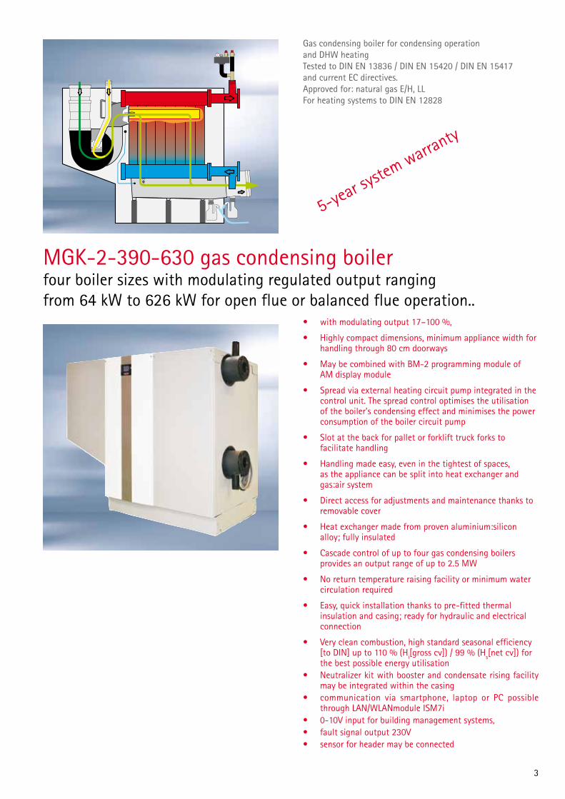
Gas condensing boiler for condensing operation and DHW heatingTested to DIN EN 13836 / DIN EN 15420 / DIN EN 15417 and current EC directives.Approved for: natural gas E/H, LL For heating systems to DIN EN 12828
5-year sy
stem warranty
• with modulating output 17–100 %,
• Highly compact dimensions, minimum appliance width for handling through 80 cm doorways
• May be combined with BM-2 programming module of AM display module
• Spread via external heating circuit pump integrated in the control unit. The spread control optimises the utilisation of the boiler's condensing effect and minimises the power consumption of the boiler circuit pump
• Slot at the back for pallet or forklift truck forks to facilitate handling
• Handling made easy, even in the tightest of spaces, as the appliance can be split into heat exchanger and gas:air system
• Direct access for adjustments and maintenance thanks to removable cover
• Heat exchanger made from proven aluminium:silicon alloy; fully insulated
• Cascade control of up to four gas condensing boilers provides an output range of up to 2.5 MW
• No return temperature raising facility or minimum water circulation required
• Easy, quick installation thanks to pre-fitted thermal insulation and casing; ready for hydraulic and electrical connection
• Very clean combustion, high standard seasonal efficiency [to DIN] up to 110 % (Hi[gross cv]) / 99 % (Hs[net cv]) for the best possible energy utilisation
• Neutralizer kit with booster and condensate rising facility may be integrated within the casing
• communication via smartphone, laptop or PC possible through LAN/WLANmodule ISM7i
• 0-10V input for building management systems,• fault signal output 230V• sensor for header may be connected
MGK-2-390-630 gas condensing boilerfour boiler sizes with modulating regulated output ranging from 64 kW to 626 kW for open flue or balanced flue operation..

4
Specification MGK-2-130-300Typ MGK-2 130 170 210 250 300
Rated heating output at 80/60 °C kW 118 157 196 233 275
Rated heating output at 50/30 °C kW 126 167 208 250 294
Rated heat input kW 120 160 200 240 280
Low heating output (modul.) at 80/60 °C kW 23 27 34 39 45
Low heating output (modul.) at 50/30 °C kW 24 30 37 44 49
Low heat input (modulating) kW 23 28 35 41 46
Heat input modulation range % 19-100 17-100 17-100 17-100 17-100
Efficiency η 80/60 at Qmax % 98,1 98,0 98,1 97,2 98,0
η 50/30 at Qmax % 104,1 104,2 104,3 103,9 105,2
η TR30 at 30 % % 107,8 106,5 106,2 105,5 106,8
Overall height A mm 1300 1300 1300 1300 1300
Overall width B mm 995 1355 1355 1355 1355
Total depth / depth excl. casing C mm 640 640 640 640 640
Flue diameter mm 160 160 160 160 200
Combustion air supply 4) mm 160 160 160 160 160
Heating flow G 1½“ 2“ 2“ 2“ 2“
Heating return G 1½ 2“ 2“ 2“ 2“
Gas connection R 1“ 1½“ 1½“ 1½“ 1½“
Air/flue gas routing Type B23, B33C33, C43C53, C63
C83
B23, B33C33, C43C53, C63
C83
B23, B33C33, C43C53, C63
C83
B23, B33C33, C43C53, C63
C83
B23, B33C33, C43C53, C63
C83
Gas category Germany II2ELL3P II2ELL3P II2ELL3P II2ELL3P II2ELL3P
Austria II2H3P II2H3P II2H3P II2H3P II2H3P
Switzerland I2H I2H I2H I2H I2H
Gas supply details:
Natural gas E/H (Hi[net cv] = 9.5 kWh/m³ = 34.2 MJ/m³ m³/h 13,1 16,8 21 25,2 29,4
Natural gas LL (Hi[net cv] = 8.6 kWh/m³ = 31.0 MJ/m³) 1) m³/h 14,6 18,6 23,3 27,9 32,6
Flüssiggas P (Hi = 12,8 kWh/kg = 46,1 MJ/kg) 2) kg/h 9,7 12,5 15,6 18,7 21,8
Gas supply pressure: Natural gas E/LL mbar 20 20 20 20 20
Gas supply pressure: Flüssiggas P mbar 50 50 50 50 50
Water content, heating water heat exchanger l 12 15,4 16 20 22
Max. permissible boiler pressure bar 6 6 6 6 6
Max. permissible flow temperature °C 90 90 90 90 90
Available gas fan draught Pa 10-200 10-150 10-150 10-150 10-150
Flue gas temperature 80/60-50/30 at Qmax °C 65-45 65-45 65-45 65-45 65-45
Flue gas temperature 80/60-50/30 at Qmin °C 55-35 55-35 55-35 55-35 55-35
Flue gas mass flow rate g/s 56,7 72,6 90,8 108,9 127,1
Flue gas category to DVGW G 635 G52 G52 G52 G52 G52
Heating water pressure drop mbar 95 100 115 135 160
Power supply V~/Hz 1~ NPE / 230VAC / 50Hz
Fitted fuse (medium slow)) A 4 4 4 4 4
Power consumption in standby W 5,0 5,0 5,0 5,0 5,0
Power consumption (partial load / full load) W 30 / 240 42 / 258 42 / 291 43 / 326 48 / 350
IP rating IP20 IP20 IP20 IP20 IP20
Sound pressure level at carga completa 3) dB(A) <54 <54 <54 <54 <54
Total weight (dry) kg 195 250 271 292 313
Condensate volume at 40/30 °C Ltr./h 12 16 20 24 28
Condensate pH value ca. 4,0 ca. 4,0 ca. 4,0 ca. 4,0 ca. 4,0
CE ID 0085CN0326 0085CN0326 0085CN0326 0085CN0326 0085CN03261) Not applicable to Austria / Switzerland2) Not applicable to Switzerland3) This value depends on general system conditions, such as: Type/version of flue system, size and nature of installation room

5
Specification MGK-2-130-300
Connections:
1 Flue gas connection2 Heating flow3 Combustion air supply4 Heating return5 Gas connection6 Cable passage
MGK-2-170/210/250/300
1187
9353
350
730890
344
9353
290420
545664
850
344
480
1 2 3 4 5 6 1 23 4 5 6
140
C
A
B
MGK-2-130

6
Specification MGK-2-390-630Type MGK-2 390 470 550 630
Rated heating output at 80/60 °C kW 366.7 434.7 511.6 584.4
Rated heating output at 50/30 °C kW 392.0 467.1 549.3 626.6
Rated heat input kW 371.2 443.6 521.0 593.9
Low heating output (modul.) at 80/60 °C kW 58.5 70.7 84.5 96.7
Low heating output (modul.) at 50/30 °C kW 64.2 78.7 94.0 106.8
Low heat input (modulating) kW 59.5 73.2 86.8 98.5
Heat input modulation range % 17-100 17-100 17-100 17-100
Efficiency η 80/60 at Qmax % 98.8 98.0 98.2 98.4
η 50/30 at Qmax % 105.6 105.3 105.4 105.5
η TR30 at 30 % % 107.8 108.9 108.6 107.6
standardised efficiency factor bei 40 / 30°C % 109,9 110,1 110,3 110,4
bei 75 / 60°C % 106,4 106,4 106,3 106,3
Overall height D/A mm 1460/1420 1460/1420 1460/1420 1460/1420
Overall widthB mmE mm
1860(1295 geteilt)
1860(1295 geteilt)
1860(1295 geteilt)
1860(1295 geteilt)
Total depth / depth excl. casing C mm 850 / 790 850 / 790 850 / 790 850 / 790
Flue diameter mm 250 250 250 250
Combustion air supply mm 200 200 200 200
Heating flow DN 80 PN6 80 PN6 80 PN6 80 PN6
Heating return DN 80 PN6 80 PN6 80 PN6 80 PN6
Gas connection R 2" 2" 2" 2"
Air/flue gas routing Type B23, B23P, C33, C43, C53, C63,
C83, C93
B23, B23P, C33, C43, C53, C63,
C83, C93
B23, B23P, C33, C43, C53, C63,
C83, C93
B23, B23P, C33, C43, C53, C63,
C83, C93
Gas category Germany I2ELL I2ELL I2ELL I2ELL
Austria / Switzerland I2H I2H I2H I2H
Gas supply details:
Natural gas E/H (Hi[net cv] = 9.5 kWh/m³ = 34.2 MJ/m³) m³/h 39.1 46.7 54.8 62.5
Natural gas LL (Hi[net cv] = 8.6 kWh/m³ = 31.0 MJ/m³) 1) m³/h 43.2 51.6 60.6 69.1
Gas supply pressure: Natural gas E/H/LL mbar 20 20 20 20
Water content, heating water heat exchanger l 50 56 62 68
Max. permissible boiler pressure bar 6 6 6 6
Max. permissible flow temperature °C 85 85 85 85
Available gas fan draught Pa 150 150 150 150
Stand-by losses overtemperature 30/50 K % 0,11 / 0,18 0,10 / 0,17 0,09 / 0,15 0,09 / 0,14
Flue gas temperature 80/60-50/30 at Qmax °C 65-35 65-35 65-35 65-35
Flue gas temperature 80/60-50/30 at Qmin °C 60-30 60-30 60-30 60-30
Flue gas mass flow rate g/s 156.3 185.2 225.3 247.4
Flue gas category to DVGW G 635 G 52 G 52 G 52 G 52
Heating water pressure drop mbar 120 113 126 118
Power supply protection V~/Hz1~ NPE / 230 V AC / 50 Hz
Alternative: 3~ PE / 400 V AC / 50 Hz
Heating circuit pump output / ZHP protection V~/Hz1~ NPE / 230 V AC / 50 Hz / 4 A
Alternative: 3~ PE / 400 V AC / 50 Hz / 4 A
Power consumption (partial load / full load) W 42 - 410 45 - 490 48 - 580 50 - 660
Power consumption in standby W 11 11 11 11
IP rating IP20 IP20 IP20 IP20
Sound power level to DIN EN 150036 part 1, balanced flue dB(A) 61 66 68 68
Sound pressure level at 1 m distance from the MGK-2, balanced flue 2) dB(A) 44 49 50 50
Sound power level to DIN EN 150036 part 1, open flue dB(A) 78 82 84 84
Sound pressure level at 1 m distance from the MGK-2, balanced flue 2) dB(A) 60 64 65 65
Total weight (dry) kg 390 420 450 480
Condensate volume at 40/30 °C l/h 39 46 52 59
Condensate pH value approx. 4.0 approx. 4.0 approx. 4.0 approx. 4.0
CE ID 0085CN0326 0085CN0326 0085CN0326 0085CN03261) Not applicable to Austria / Switzerland2) This value depends on general system conditions, such as: Type/version of flue system, size and nature of installation room
7
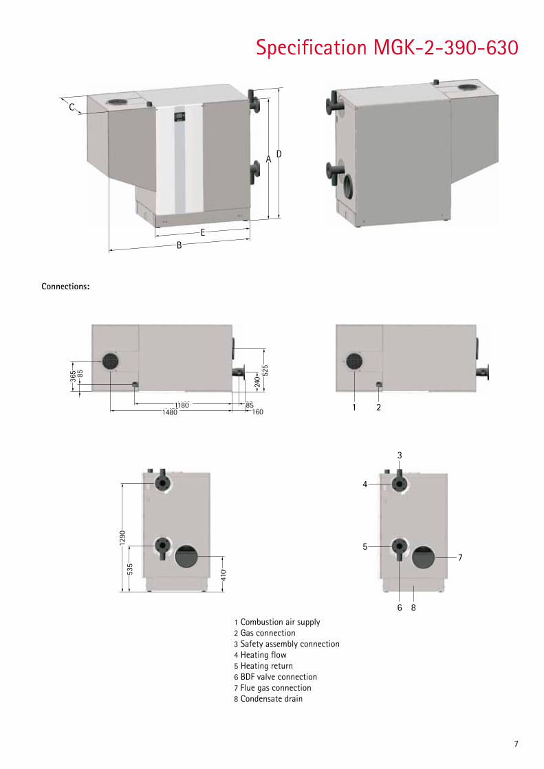
Specification MGK-2-390-630
1 Combustion air supply2 Gas connection3 Safety assembly connection4 Heating flow5 Heating return6 BDF valve connection7 Flue gas connection8 Condensate drain
535
1290
410
1 2
3
4
5
6 8
7
A
C
BB
E
D
85
85
1601480
1180
525
240365
365 85
11801480
240 52
5
85160
Connections:
C
A
B
D
E
535
1290
410

8
Standard control unit
The operation of the MGK-2 requires either an AM display module or a BM-2 programming module.
The BM-2 (programming module) communicates with all connected extension modules and with the boiler via the eBUS.
Specification:• 3.5"colourdisplay• 4functionkeys• 1rotaryselectorwithkeyfunction• SDcardslotforsoftwareupdate• Centralprogrammingunitwithweather-compensated
flow temperature• Timeprogramsforheating,DHWheatingand
DHW circulation
The AM acts exclusively as display module for the boiler. Pa-rameter and values that are specific to the individual boiler can be programmed or displayed.
Specification:• 3"LCD• 4quickstartkeys• 1rotaryselectorwithkeyfunction
Please note:• RequirediftheBM-2isusedasremotecontrol
or in a cascade• AMalwaysontheboiler
AM
BM2
14:12 20.01.2013
1,5 bar
25,2 °C
boiler temperature
heater
heating-/hot water generation
pressure1x
Operating mode
Heating mode
Burner status
On
Status

9
Control accessories
Either an AM display module or BM-2 programming module is required
BM-2 programming module (incl. outside temperature sensor)Weather-compensated flow temperature•Timeprogramsforheating,DHWheating
and DHW circulation•3.5"colourdisplay•Easyuserpromptswithplaintextdisplay•Operationbyrotaryselectorwithkeyfunction•4functionkeysforfrequentlyusedfunctions•Installationeitherinsidetheboilercontrolunit,or
as a remote control in a wall mounting base•Onlyoneprogrammingmodulerequiredformulti
boiler systems•CanbeextendedwithMMmixermodule
(up to 7 heating circuits with mixer)
AM display module•Boilerdisplaymodule•OnlyrequirediftheBM-2isusedas
remote control or in a cascade•Operationbyrotaryselectorwithkeyfunction•4quickstartkeysforfrequentlyusedfunctions•BacklitLCD
2-w
ire e
BUS
conn
ectio
n
or
BM-2 programming module (if the BM-2 is fitted inside the boiler then up to 6 additional remote control units may be used)Weather-compensated flow temperature•Timeprogramsforheating,DHWheatingandDHWcirculation•3.5"colourdisplay•Easyuserpromptswithplaintextdisplay•Operationbyrotaryselectorwithkeyfunction•4functionkeysforfrequentlyusedfunctions•Installationeitherinsidetheboilercontrolunit,orasaremotecontrol
in a wall mounting base•Onlyoneprogrammingmodulerequiredformultiboilersystems•CanbeextendedwithMMmixermodule(upto7heatingcircuitswithmixer)

10
KM cascade module•Extensionmoduleforcontrollingsystemswithalow
loss header or in a cascade•Canbeusedforconventionalgasboilercontrolunits
(4 appliances)•Easycontrollerconfigurationbyselectingoneof
the preset system versions•Controlofoneheatingcircuitwithmixer•BM-2programmingmodulecanbeextendedtoactasaremotecontrol•0-10VinputforBMS;faultmessageoutput230V•eBUSinterfacewithautomaticenergymanagement•Rast5connectiontechnology
Control accessories2-
wire
eBU
S co
nnec
tion
MM mixer module•Extensionmoduleforregulatingoneheatingcircuit
with mixer•Weather-compensatedflowtemperaturecontrol•Easycontrollerconfigurationbyselectingoneof
the preset system versions•BM-2programmingmoduleextended
with a wall mounting base to act as a remote control
•Rast5connectiontechnology•Incl.flowtemperaturesensor
1 ... 7
SM2 solar module•Extensionmoduletocontrolonesolarthermal
system with up to 2 cylinders and 2 collector arrays, incl. 1 collector sensor and 1 cylinder sensor, each with sensor well
•Easycontrollerconfigurationbyselectingoneofthe preset system versions
•InconjunctionwithWolfboilers,greaterenergysavings through intelligent cylinder reheating, i.e. blocking cylinder reheating when there is sufficient solar yield
•Capturingtheamountofheat•DisplayofthesetandactualvaluesontheBM-2programmingmodule•eBUSinterfacewithautomaticenergymanagement•Rast5connectiontechnology
SM1 solar module•Extensionmoduleforregulatingonesolarcircuit• InconjunctionwithWolfboilers,greaterenergysavings
through intelligent cylinder reheating, i.e. blocking cylinder reheating when there is sufficient solar yield
•Temperaturedifferentialcontrolforoneheatconsumer•Maximumcylindertemperaturelimit•DisplayofthesetandactualvaluesontheBM-2
programming module•Integralhoursrunmeter•Optionalconnectionofheatmeters•Rast5connectiontechnology•Incl.collectorsensorandcylindersensor,eachwithsensorwell

11
Wolf-Portal-Server
local (Home-) Network
DSL-Router(LAN / WLAN)
WLA
N
LAN / WLAN
LAN
/ W
LAN
LAN
ISM7i
LAN / WLAN interface
Control accessories2-
wire
eBU
S co
nnec
tion
Wireless receiver for wireless outside temperature sensor and wireless remote controlincl. wireless clock (DCF77 signal)
Wireless remote control (only in conjunction with a receiver for wireless outside temperature sensor and remote control) up to one wireless remote control per heating circuit with mixer.
Wireless outside temperature sensor (only in conjunction with receiver for wireless outside temperature sensor and remote control, part no. 27 44 209)
Wireless clock (DCF77 signal) with outside temperature sensorfor automatic time setting.
Wireless clock (DCF77 signal)for automatic time setting.
ISM7i LAN / WLAN interface for access to the control unit via the internet or a local area network. Operation via iPhone app, Wolf-Portal or PC software.Comprising an ISM7i interface module and PC software for loading into the appliance control unit.

12
Wolf GmbH, PO Box 1380, D-84048 Mainburg, Tel.: +49 87 51 / 74-0, Fax: +49 87 51 / 74-1600, Internet: www.wolf-heiztechnik.de
The comprehensive equipment range from system supplier Wolf offers the ideal solution for commercial and industrial buil-dings, for new build and for modernisation projects alike. The range of Wolf control units fulfils every need where heating con-venience is concerned. The products are easy to operate, energy-efficient and reliable. Photovoltaic and solar heating systems can be quickly integrated into existing systems. All Wolf products can be easily and rapidly commissioned and maintained.
The competence brand for energy saving systems
Art.Nr. 4800745 Subj
ect
to t
echn
ica
mod
ifica
tions
2015
/02
GB