Technical Description of the 2.3m Telescope...
46
ARISTARCHOS 2.3m Telescope System Documentation Volume 5 Technical Description 5_4 doc. no: TELEGR_CZJ_5_4_TD_01.doc date: 31/03/2005 issue: 01 Carl Zeiss Jena Acquisition and Guiding System page : 1/ 46 Print date: 17.03.2005 Technical Description of the 2.3m Telescope System Volume 5_4 Acquisition and Guiding System (AGU) Content of Volume 5_4 Technical Description of the 2.3m Telescope System ............................................................................................1 Volume 5_4 Acquisition and Guiding System (AGU) ..............................................................................................1 5.4 Acquisition and Guiding Unit....................................................................................................................3 5.4.1 Overview ..........................................................................................................................................3 5.4.2 AGU modules housing .....................................................................................................................4 5.4.3 Introduction to the electrics installation............................................................................................5 5.4.4 AGU module 1 with AGS probe arms ..............................................................................................7 5.4.4.1 Auto guider probe patrol fields .....................................................................................................9 5.4.4.2 Guider probe positions.................................................................................................................9 5.4.4.3 Probe arm movements ..............................................................................................................12 5.4.4.4 Linear movement .......................................................................................................................12 5.4.4.5 Swivel motion .............................................................................................................................13 5.4.4.6 Pick up mirror .............................................................................................................................15 5.4.4.7 Astigmatism corrector ................................................................................................................16 5.4.4.8 Astigmatism corrector drive .......................................................................................................17 5.4.4.9 Shortener system.......................................................................................................................18 5.4.4.10 Focus movement ...................................................................................................................18 5.4.4.11 Focus drive ............................................................................................................................18 5.4.4.12 Auto guiding filter wheel .........................................................................................................20 5.4.4.13 Auto guider filter wheel drive .................................................................................................25 5.4.4.14 General electrics installation of module 1 ..............................................................................26 5.4.5 Module 2 with science fold mirror and rotator................................................................................27 5.4.5.1 Module 2 General description ....................................................................................................27 5.4.5.2 General electrics installation for module 2.................................................................................29 5.4.5.3 Rotary table................................................................................................................................30 5.4.5.4 Science fold mirror in mount ......................................................................................................32 5.4.5.5 Linear movement for science fold mirror ...................................................................................32 5.4.5.6 Science fold mirror tilt ................................................................................................................33 5.4.5.7 Module 2 housing with instrument side ports ............................................................................34 5.4.5.8 Filter unit ....................................................................................................................................35 5.4.5.9 External filter unit drive and electrics .........................................................................................41 5.4.6 Module 3 with main port and corrector optics ................................................................................42 5.4.6.1 Module 3 general description.....................................................................................................42 5.4.6.2 Corrector optics system .............................................................................................................43 5.4.6.3 Science CCD camera –mechanical and optical interface .........................................................46
-
Upload
vuongkhanh -
Category
Documents
-
view
217 -
download
1
Transcript of Technical Description of the 2.3m Telescope...
ARISTARCHOS 2.3m Telescope System
Documentation Volume 5 Technical Description 5_4
doc. no: TELEGR_CZJ_5_4_TD_01.doc date: 31/03/2005 issue: 01
Carl Zeiss Jena Acquisition and Guiding System page : 1/ 46
Print date: 17.03.2005
Technical Description of the 2.3m Telescope System
Volume 5_4 Acquisition and Guiding System (AGU)
Content of Volume 5_4
Technical Description of the 2.3m Telescope System ............................................................................................1 Volume 5_4 Acquisition and Guiding System (AGU) ..............................................................................................1
5.4 Acquisition and Guiding Unit....................................................................................................................3 5.4.1 Overview ..........................................................................................................................................3 5.4.2 AGU modules housing.....................................................................................................................4 5.4.3 Introduction to the electrics installation............................................................................................5 5.4.4 AGU module 1 with AGS probe arms..............................................................................................7
5.4.4.1 Auto guider probe patrol fields.....................................................................................................9 5.4.4.2 Guider probe positions.................................................................................................................9 5.4.4.3 Probe arm movements ..............................................................................................................12 5.4.4.4 Linear movement .......................................................................................................................12 5.4.4.5 Swivel motion.............................................................................................................................13 5.4.4.6 Pick up mirror.............................................................................................................................15 5.4.4.7 Astigmatism corrector ................................................................................................................16 5.4.4.8 Astigmatism corrector drive .......................................................................................................17 5.4.4.9 Shortener system.......................................................................................................................18 5.4.4.10 Focus movement ...................................................................................................................18 5.4.4.11 Focus drive ............................................................................................................................18 5.4.4.12 Auto guiding filter wheel.........................................................................................................20 5.4.4.13 Auto guider filter wheel drive .................................................................................................25 5.4.4.14 General electrics installation of module 1..............................................................................26
5.4.5 Module 2 with science fold mirror and rotator................................................................................27 5.4.5.1 Module 2 General description....................................................................................................27 5.4.5.2 General electrics installation for module 2.................................................................................29 5.4.5.3 Rotary table................................................................................................................................30 5.4.5.4 Science fold mirror in mount ......................................................................................................32 5.4.5.5 Linear movement for science fold mirror ...................................................................................32 5.4.5.6 Science fold mirror tilt ................................................................................................................33 5.4.5.7 Module 2 housing with instrument side ports ............................................................................34 5.4.5.8 Filter unit ....................................................................................................................................35 5.4.5.9 External filter unit drive and electrics .........................................................................................41
5.4.6 Module 3 with main port and corrector optics................................................................................42 5.4.6.1 Module 3 general description.....................................................................................................42 5.4.6.2 Corrector optics system .............................................................................................................43 5.4.6.3 Science CCD camera –mechanical and optical interface .........................................................46
ARISTARCHOS 2.3m Telescope System
Documentation Volume 5 Technical Description 5_4
doc. no: TELEGR_CZJ_5_4_TD_01.doc date: 31/03/2005 issue: 01
Carl Zeiss Jena Acquisition and Guiding System page : 2/ 46
Print date: 17.03.2005
List of figures Fig. 5.4_1. Scheme of the Acquisition and Guiding Unit (AGU) ........................................................................3 Fig. 5.4_2. Connector interfaces........................................................................................................................6 Fig. 5.4_3. Additional Interfaces ........................................................................................................................6 Fig. 5.4_4. Power supply for guider cameras ....................................................................................................6 Fig. 5.4_5. AGS probe arms (module 1 housing removed) ...............................................................................7 Fig. 5.4_6. AGS probe arm details ....................................................................................................................8 Fig. 5.4_7. Home position ..................................................................................................................................9 Fig. 5.4_8. Probe arm axis parallel to the slide axis ........................................................................................10 Fig. 5.4_9. 180°position ...................................................................................................................................10 Fig. 5.4_10. 270°position ...................................................................................................................................11 Fig. 5.4_11. 360° position ..................................................................................................................................11 Fig. 5.4_12. Linear movement drive ..................................................................................................................12 Fig. 5.4_13. Linear tape encoder.......................................................................................................................12 Fig. 5.4_14. Swivel drive....................................................................................................................................13 Fig. 5.4_15. Swivel axis limits ............................................................................................................................14 Fig. 5.4_16. Swivel sensor.................................................................................................................................14 Fig. 5.4_17. Collision switches ..........................................................................................................................14 Fig. 5.4_18. Pick up mirror, fixed on the AGS probe arm..................................................................................15 Fig. 5.4_19. AGS optical elements ....................................................................................................................16 Fig. 5.4_20. Astigmatism drive ..........................................................................................................................17 Fig. 5.4_21. Init sensor ......................................................................................................................................17 Fig. 5.4_22. Drive interface for astigmatism correction .....................................................................................17 Fig. 5.4_23. Focus drive ....................................................................................................................................18 Fig. 5.4_24. Focus limit......................................................................................................................................19 Fig. 5.4_25. Blue filter (B) ..................................................................................................................................20 Fig. 5.4_26. Red filter (R)...................................................................................................................................21 Fig. 5.4_27. Red filter (R0.3)..............................................................................................................................22 Fig. 5.4_28. Green filter (V) ...............................................................................................................................23 Fig. 5.4_29. IR filter (I) .......................................................................................................................................24 Fig. 5.4_30. Filter wheel at probe arms .............................................................................................................25 Fig. 5.4_31. Internal interfaces ..........................................................................................................................26 Fig. 5.4_32. Cables input and distribution .........................................................................................................26 Fig. 5.4_33. Cable chains ..................................................................................................................................26 Fig. 5.4_34. Module 2, SFM in working position................................................................................................27 Fig. 5.4_35. Module 2, SFM in home position ...................................................................................................28 Fig. 5.4_36. Interface for electrics hardware unit 3 ...........................................................................................29 Fig. 5.4_37. Cable installation for science fold system......................................................................................29 Fig. 5.4_38. View at the drive system................................................................................................................30 Fig. 5.4_39. Turn table init sensor .....................................................................................................................30 Fig. 5.4_40. Brake mechanism ..........................................................................................................................31 Fig. 5.4_41. Limit switches for rotary table ........................................................................................................31 Fig. 5.4_42. Linear drive system........................................................................................................................32 Fig. 5.4_43. Limit switches.................................................................................................................................33 Fig. 5.4_44. Science fold mirror drive ................................................................................................................33 Fig. 5.4_45. Side port interfaces........................................................................................................................34 Fig. 5.4_46. Filter unit, change of user filter ......................................................................................................35 Fig. 5.4_47. Blue filter (B) ..................................................................................................................................36 Fig. 5.4_48. Red filter (R)...................................................................................................................................37 Fig. 5.4_49. Green filter (V) ...............................................................................................................................38 Fig. 5.4_50. Infra red filter (I) .............................................................................................................................39 Fig. 5.4_51. UV filter (U) ....................................................................................................................................40 Fig. 5.4_52. External filter unit, shown without filter ..........................................................................................41 Fig. 5.4_53. Module 3 inside view .....................................................................................................................42 Fig. 5.4_54. Module 3 backside view with the assembled filter unit and CCD camera.....................................43 Fig. 5.4_55. Module 3 instrument interface .......................................................................................................44 Fig. 5.4_56. Main port instrument interface with science filter unit....................................................................45 Fig. 5.4_57. Science CCD camera with adapter ...............................................................................................46

ARISTARCHOS 2.3m Telescope System
Documentation Volume 5 Technical Description 5_4
doc. no: TELEGR_CZJ_5_4_TD_01.doc date: 31/03/2005 issue: 01
Carl Zeiss Jena Acquisition and Guiding System page : 3/ 46
Print date: 17.03.2005
5.4 Acquisition and Guiding Unit Reference drawing: a) 019904:001.26 (0), pg.1
Fig. 5.4_1. Scheme of the Acquisition and Guiding Unit (AGU)
5.4.1 Overview The Acquisition and Guiding Unit (AGU) is mounted on the Cassegrain rotator of the telescope. The AGU provides 5 focal stations for the astronomical instruments, one for the corrected field with 1.05° diameter and four side looking focal stations for the field with 10arcmin diameter. The science fold Mirror directs the light from the telescope to any of the side looking focal stations. The AGU also provides an offset guiding system (AGS). The AGS patrols a wide field to find bright stars, off axis from the target of interest to the astronomer. All these functions are to be carried out with reduced vignette of the path of the science beam, or without introducing stray light or extra emission at the science focal plane. The AGU has the following functions: 1. Instrument support:
The unit supports different scientific instruments on five ports. The most important port is located on the backside. This is the port for the corrected field of view (1.05°). Four other ports are located at the sides of the unit (side looking ports).
The summary of the weight of four instrument in the side looking support can be 300 kg with a distance of the centre of gravity of the instrument ≤ 300mm from the instrument flange. The mass of one instrument should not be more than 100kg.
The mass of the instrument at the backside focus can be 300kg with a distance of the instrument centre of gravity ≤ 300mm from the instrument flange.
The distance of the focal plane from the instrument port flanges will be 130mm (nominal). By integration of the filter unit the distance will be reduced to 70mm (nominal). The detailed value can be seen in the description of the optical system.
Module 1
Module 2
Camera
Cover for AGS
Side port for instruments
Flange to rotator
Module 3
ARISTARCHOS 2.3m Telescope System
Documentation Volume 5 Technical Description 5_4
doc. no: TELEGR_CZJ_5_4_TD_01.doc date: 31/03/2005 issue: 01
Carl Zeiss Jena Acquisition and Guiding System page : 4/ 46
Print date: 17.03.2005
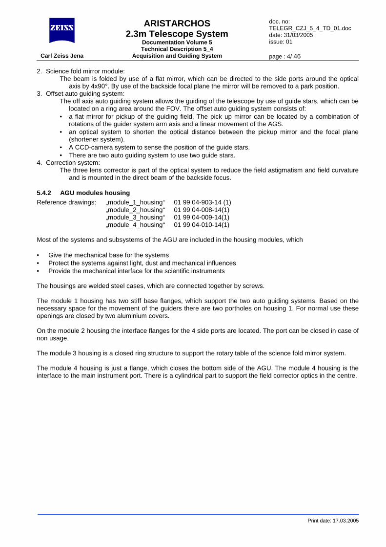
2. Science fold mirror module: The beam is folded by use of a flat mirror, which can be directed to the side ports around the optical
axis by 4x90°. By use of the backside focal plane the mirror will be removed to a park position. 3. Offset auto guiding system:
The off axis auto guiding system allows the guiding of the telescope by use of guide stars, which can be located on a ring area around the FOV. The offset auto guiding system consists of:
• a flat mirror for pickup of the guiding field. The pick up mirror can be located by a combination of rotations of the guider system arm axis and a linear movement of the AGS.
• an optical system to shorten the optical distance between the pickup mirror and the focal plane (shortener system).
• A CCD-camera system to sense the position of the guide stars. • There are two auto guiding system to use two guide stars.
4. Correction system: The three lens corrector is part of the optical system to reduce the field astigmatism and field curvature
and is mounted in the direct beam of the backside focus.
5.4.2 AGU modules housing Reference drawings: „module_1_housing“ 01 99 04-903-14 (1) „module_2_housing“ 01 99 04-008-14(1) „module_3_housing“ 01 99 04-009-14(1) „module_4_housing“ 01 99 04-010-14(1) Most of the systems and subsystems of the AGU are included in the housing modules, which • Give the mechanical base for the systems • Protect the systems against light, dust and mechanical influences • Provide the mechanical interface for the scientific instruments The housings are welded steel cases, which are connected together by screws. The module 1 housing has two stiff base flanges, which support the two auto guiding systems. Based on the necessary space for the movement of the guiders there are two portholes on housing 1. For normal use these openings are closed by two aluminium covers. On the module 2 housing the interface flanges for the 4 side ports are located. The port can be closed in case of non usage. The module 3 housing is a closed ring structure to support the rotary table of the science fold mirror system. The module 4 housing is just a flange, which closes the bottom side of the AGU. The module 4 housing is the interface to the main instrument port. There is a cylindrical part to support the field corrector optics in the centre.
ARISTARCHOS 2.3m Telescope System
Documentation Volume 5 Technical Description 5_4
doc. no: TELEGR_CZJ_5_4_TD_01.doc date: 31/03/2005 issue: 01
Carl Zeiss Jena Acquisition and Guiding System page : 5/ 46
Print date: 17.03.2005
5.4.3 Introduction to the electrics installation Reference drawings: a) 019904:001.26 (Sp), pg. 1 b) 019904:001.26 (Sp), pg. 2 c) 019904:001.26 (Sp), pg. 3 d) 160601:001.26 (Sp), pg. 13 e) 160601:001.26 (Sp), pg. 8 The electrics installation of the AGU unit consists of three components, electrics hardware unit 1 (ref. a), electrics hardware unit 2 (ref. b) and electrics hardware unit 3 (ref. c). The expression „electrics hardware unit“ means a complete probe-arm. The electrics hardware units 1 and 2 are both by principle identical. So the description of one unit is representative for both. The electrics hardware unit 3 is the complete science fold mechanism, including rotary table. The electrics hardware unit 3 is completely different and will be described separately. The AGU is integrated at the rotator axis of the telescope. That’s why the cable installation for all consumers is accomplished through the rotator cable wrap. For cables and signals of the AGU supply refer to reference e). Each of the units has its own connector interface. To minimize the number of installed cables through the telescope, the voltages for the encoder supply will be distributed from unit 2 (voltage input from cable wrap) to electrics hardware unit 1 and 3 by cables G-W120 and G-W121. Axes controller, power amplifier, power supplies, interpolation units for the HEIDENHAIN encoders etc. are integrated in the JAT control cabinet. For the linear LIE NUMERIK encoders, the interpolation electronics is placed in the encoder heads itself. Onto the housings of the AGU modules the scientific CCD controller is installed. The integrated guider cameras implement the appropriate controller. The mains supply units are also fixed onto the AGU- housing from the outside. For details of the CCD-mains supply and fibre-optics interfaces refer to reference d).
ARISTARCHOS 2.3m Telescope System
Documentation Volume 5 Technical Description 5_4
doc. no: TELEGR_CZJ_5_4_TD_01.doc date: 31/03/2005 issue: 01
Carl Zeiss Jena Acquisition and Guiding System page : 6/ 46
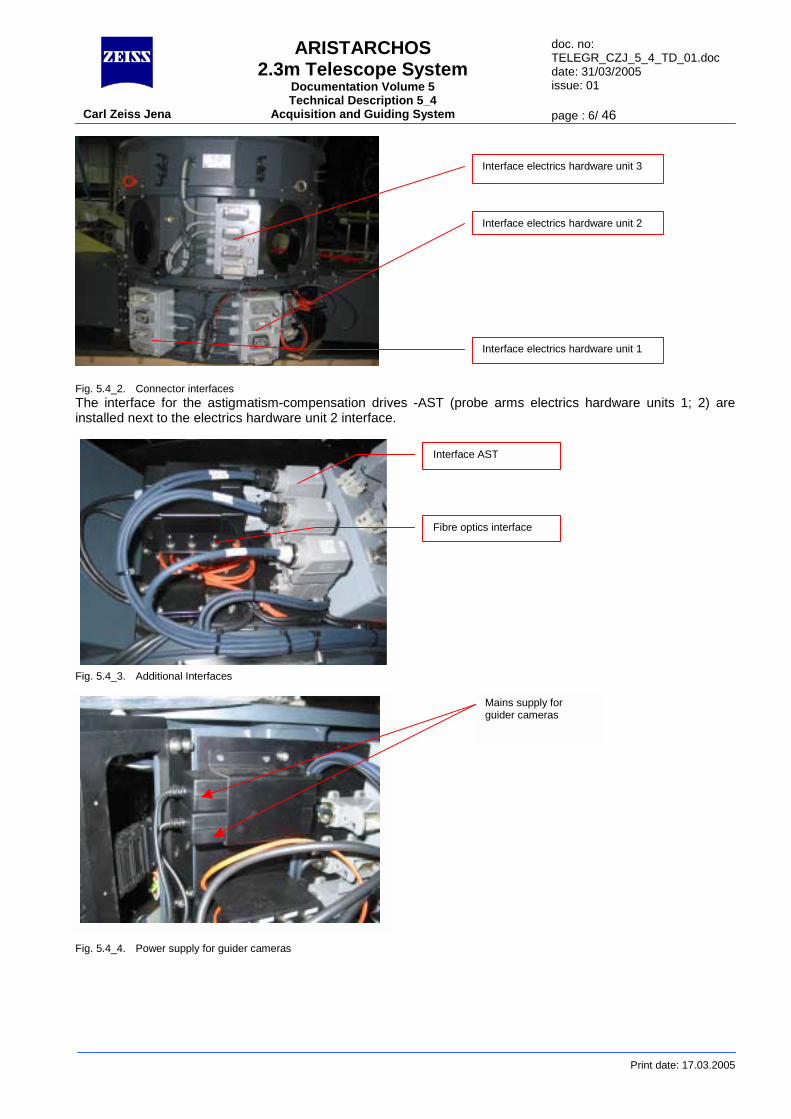
Fig. 5.4_2. Connector interfaces The interface for the astigmatism-compensation drives -AST (probe arms electrics hardware units 1; 2) are installed next to the electrics hardware unit 2 interface.Interface electrics hardware unit 3
Interface electrics hardware unit 2
Interface electrics hardware unit 1
Interface AST
Print date: 17.03.2005
Fig. 5.4_3. Additional Interfaces Fig. 5.4_4. Power supply for guider cameras
Mains supply for guider cameras
Fibre optics interface
ARISTARCHOS 2.3m Telescope System
Documentation Volume 5 Technical Description 5_4
doc. no: TELEGR_CZJ_5_4_TD_01.doc date: 31/03/2005 issue: 01
Carl Zeiss Jena Acquisition and Guiding System page : 7/ 46
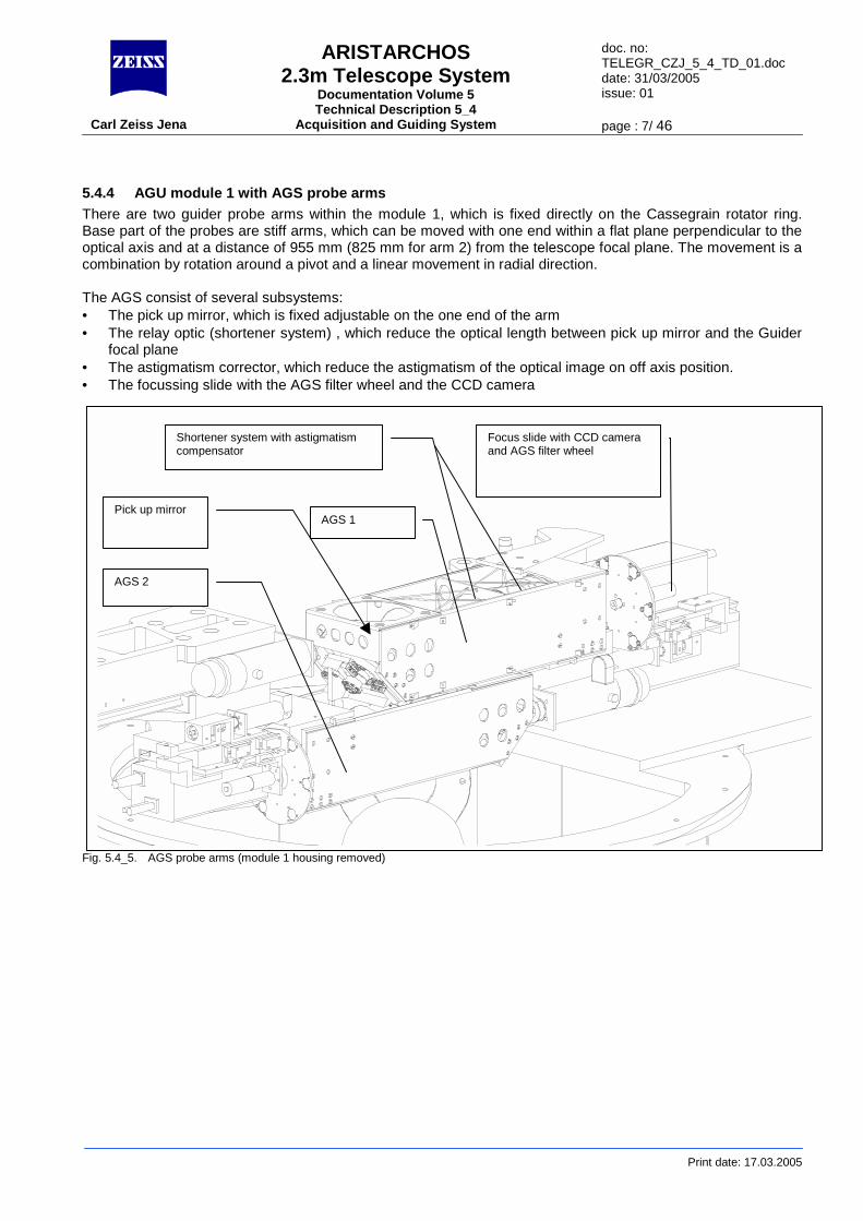
5.4.4 AGU module 1 with AGS probe arms There are two guider probe arms within the module 1, which is fixed directly on the Cassegrain rotator ring. Base part of the probes are stiff arms, which can be moved with one end within a flat plane perpendicular to the optical axis and at a distance of 955 mm (825 mm for arm 2) from the telescope focal plane. The movement is a combination by rotation around a pivot and a linear movement in radial direction. The AGS consist of several subsystems: • The pick up mirror, which is fixed adjustable on the one end of the arm • The relay optic (shortener system) , which reduce the optical length between pick up mirror and the Guider
focal plane • The astigmatism corrector, which reduce the astigmatism of the optical image on off axis position. • The focussing slide with the AGS filter wheel and the CCD camera
Fig
. 5.4_5. AGS probe arms (module 1 housing removed)
AGS 2
AGS 1 Pick up mirror
Shortener system with astigmatism compensator
Focus slide with CCD camera and AGS filter wheel
Print date: 17.03.2005

ARISTARCHOS 2.3m Telescope System
Documentation Volume 5 Technical Description 5_4
doc. no: TELEGR_CZJ_5_4_TD_01.doc date: 31/03/2005 issue: 01
Carl Zeiss Jena Acquisition and Guiding System page : 8/ 46
Print date: 17.03.2005
Fig. 5.4_6. AGS probe arm details
Swivel axis
Pick up mirror
Astigmatism compensator
Shortener system
Filter wheel
Focus drive
CCD camera
Drive for linear arm movement
ARISTARCHOS 2.3m Telescope System
Documentation Volume 5 Technical Description 5_4
doc. no: TELEGR_CZJ_5_4_TD_01.doc date: 31/03/2005 issue: 01
Carl Zeiss Jena Acquisition and Guiding System page : 9/ 46
Print date: 17.03.2005
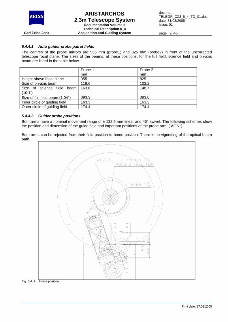
5.4.4.1 Auto guider probe patrol fields The centres of the probe mirrors are 955 mm (probe1) and 825 mm (probe2) in front of the uncorrected telescope focal plane. The sizes of the beams, at these positions, for the full field, science field and on-axis beam are listed in the table below. Probe 1
mm Probe 2 mm
Height above focal plane 955 825 Size of on-axis beam 119.6 103.2 Size of science field beam (10.1′)
163.6 148.7
Size of full field beam (1.04°) 393.3 383.0 Inner circle of guiding field 163.3 163.3 Outer circle of guiding field 174.4 174.4
5.4.4.2 Guider probe positions Both arms have a nominal movement range of ± 132.5 mm linear and 45° swivel. The following schemes show the position and dimension of the guide field and important positions of the probe arm. ( AGS1). Both arms can be rejected from their field position to home position. There is no vignetting of the optical beam path.
Fig. 5.4_7. Home position
ARISTARCHOS 2.3m Telescope System
Documentation Volume 5 Technical Description 5_4
doc. no: TELEGR_CZJ_5_4_TD_01.doc date: 31/03/2005 issue: 01
Carl Zeiss Jena Acquisition and Guiding System page : 10/ 46
Print date: 17.03.2005
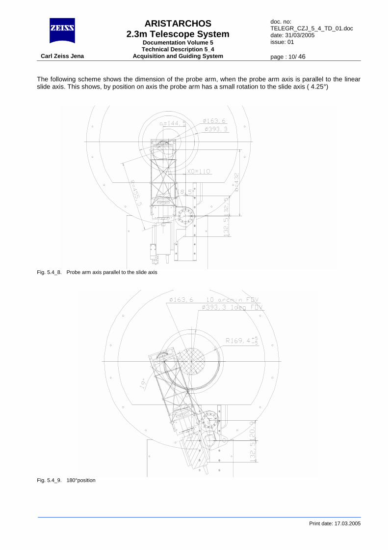
The following scheme shows the dimension of the probe arm, when the probe arm axis is parallel to the linear slide axis. This shows, by position on axis the probe arm has a small rotation to the slide axis ( 4.25°)
Fig. 5.4_8. Probe arm axis parallel to the slide axis
Fig. 5.4_9. 180°position
ARISTARCHOS 2.3m Telescope System
Documentation Volume 5 Technical Description 5_4
doc. no: TELEGR_CZJ_5_4_TD_01.doc date: 31/03/2005 issue: 01
Carl Zeiss Jena Acquisition and Guiding System page : 11/ 46
Print date: 17.03.2005
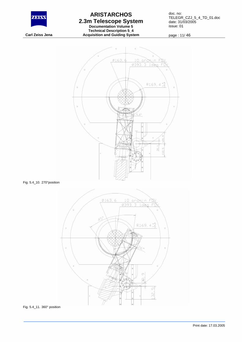
Fig. 5.4_10. 270°position
Fig. 5.4_11. 360° position
ARISTARCHOS 2.3m Telescope System
Documentation Volume 5 Technical Description 5_4
doc. no: TELEGR_CZJ_5_4_TD_01.doc date: 31/03/2005 issue: 01
Carl Zeiss Jena Acquisition and Guiding System page : 12/ 46
Print date: 17.03.2005
5.4.4.3 Probe arm movements The probe arms can move within a range of ±132.5 mm linear and 45° swivel. The base of the linear slides are fixed on a stiff plate of the module 1 housing. To save space, probe arm 1 is inversely arranged to arm 2, means, arm 1 is sitting upon the ground plate, whereas arm 2 is hanging on the top plate on the module 1 housing. The swivel pivot is moving with the linear slide.
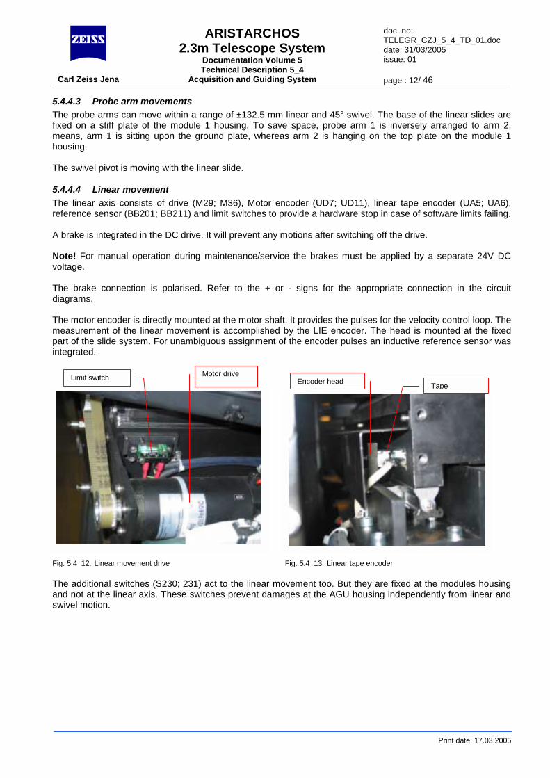
5.4.4.4 Linear movement The linear axis consists of drive (M29; M36), Motor encoder (UD7; UD11), linear tape encoder (UA5; UA6), reference sensor (BB201; BB211) and limit switches to provide a hardware stop in case of software limits failing. A brake is integrated in the DC drive. It will prevent any motions after switching off the drive. Note! For manual operation during maintenance/service the brakes must be applied by a separate 24V DC voltage. The brake connection is polarised. Refer to the + or - signs for the appropriate connection in the circuit diagrams. The motor encoder is directly mounted at the motor shaft. It provides the pulses for the velocity control loop. The measurement of the linear movement is accomplished by the LIE encoder. The head is mounted at the fixed part of the slide system. For unambiguous assignment of the encoder pulses an inductive reference sensor was integrated. Fig. 5.4_12. Linear movement drive Fig. 5.4_13. Linear tape encoder The additional switches (S230; 231) act to the linear movement too. But they are fixed at the modules housing and not at the linear axis. These switches prevent damages at the AGU housing independently from linear and swivel motion.
Limit switch Motor drive Tape Encoder head
ARISTARCHOS 2.3m Telescope System
Documentation Volume 5 Technical Description 5_4
doc. no: TELEGR_CZJ_5_4_TD_01.doc date: 31/03/2005 issue: 01
Carl Zeiss Jena Acquisition and Guiding System page : 13/ 46
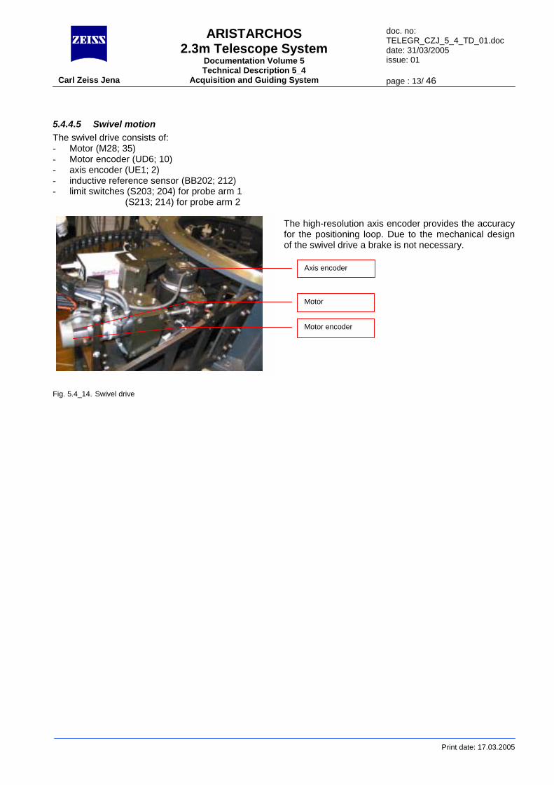
5.4.4.5 Swivel motion The swivel drive consists of: - Motor (M28; 35) - Motor encoder (UD6; 10) - axis encoder (UE1; 2) - inductive reference sensor (BB202; 212) - limit switches (S203; 204) for probe arm 1 (S213; 214) for probe arm 2
The high-resolution axis encoder provides the accuracy
Print date: 17.03.2005
for the positioning loop. Due to the mechanical design of the swivel drive a brake is not necessary.
Fig. 5.4_14. Swivel drive
Axis encoder
Motor
Motor encoder

ARISTARCHOS 2.3m Telescope System
Documentation Volume 5 Technical Description 5_4
doc. no: TELEGR_CZJ_5_4_TD_01.doc date: 31/03/2005 issue: 01
Carl Zeiss Jena Acquisition and Guiding System page : 14/ 46
An additional set of limit switches (S231; 233) was installed. These switches are not installed at the swivel axis (like ordinary switches mentioned above), but at the inside of the modules housing. They will prevent collision independently from the linear position.
Fig. 5.4_15. Swivel axis limits Fig. 5.4_17. Collision switches
Init sensor Limit switchLimit switches
Fig. 5.4_16. Swivel sensor
Axis encoder
Collision switches
Print date: 17.03.2005
ARISTARCHOS 2.3m Telescope System
Documentation Volume 5 Technical Description 5_4
doc. no: TELEGR_CZJ_5_4_TD_01.doc date: 31/03/2005 issue: 01
Carl Zeiss Jena Acquisition and Guiding System page : 15/ 46
Print date: 17.03.2005
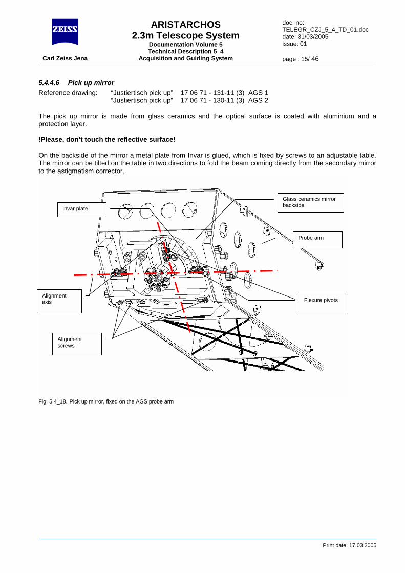
5.4.4.6 Pick up mirror Reference drawing: “Justiertisch pick up” 17 06 71 - 131-11 (3) AGS 1
“Justiertisch pick up” 17 06 71 - 130-11 (3) AGS 2 The pick up mirror is made from glass ceramics and the optical surface is coated with aluminium and a protection layer. !Please, don’t touch the reflective surface! On the backside of the mirror a metal plate from Invar is glued, which is fixed by screws to an adjustable table. The mirror can be tilted on the table in two directions to fold the beam coming directly from the secondary mirror to the astigmatism corrector.
Fig. 5.4_18. Pick up mirror, fixed on the AGS probe arm
Probe arm
Glass ceramics mirror backside Invar plate
Alignment screws
Flexure pivots Alignment axis
ARISTARCHOS 2.3m Telescope System
Documentation Volume 5 Technical Description 5_4
doc. no: TELEGR_CZJ_5_4_TD_01.doc date: 31/03/2005 issue: 01
Carl Zeiss Jena Acquisition and Guiding System page : 16/ 46
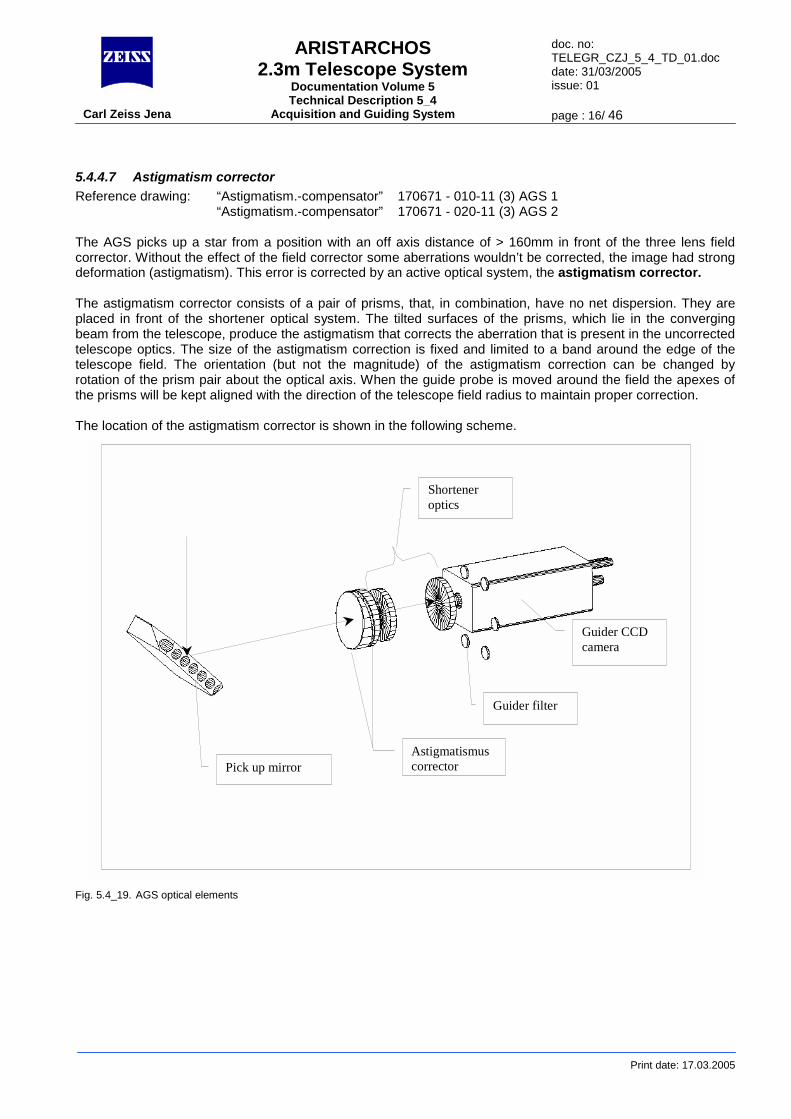
5.4.4.7 Astigmatism corrector Reference drawing: “Astigmatism.-compensator” 170671 - 010-11 (3) AGS 1 “Astigmatism.-compensator” 170671 - 020-11 (3) AGS 2 The AGS picks up a star from a position with an off axis distance of > 160mm in front of the three lens field corrector. Without the effect of the field corrector some aberrations wouldn’t be corrected, the image had strong deformation (astigmatism). This error is corrected by an active optical system, the astigmatism corrector. The astigmatism corrector consists of a pair of prisms, that, in combination, have no net dispersion. They are placed in front of the shortener optical system. The tilted surfaces of the prisms, which lie in the converging beam from the telescope, produce the astigmatism that corrects the aberration that is present in the uncorrected telescope optics. The size of the astigmatism correction is fixed and limited to a band around the edge of the telescope field. The orientation (but not the magnitude) of the astigmatism correction can be changed by rotation of the prism pair about the optical axis. When the guide probe is moved around the field the apexes of the prisms will be kept aligned with the direction of the telescope field radius to maintain proper correction. The location of the astigmatism corrector is shown in the following scheme.
Fig
Print date: 17.03.2005
Pick up mirrorAstigmatismuscorrector
Shorteneroptics
Guider filter
Guider CCDcamera
. 5.4_19. AGS optical elements
ARISTARCHOS 2.3m Telescope System
Documentation Volume 5 Technical Description 5_4
doc. no: TELEGR_CZJ_5_4_TD_01.doc date: 31/03/2005 issue: 01
Carl Zeiss Jena Acquisition and Guiding System page : 17/ 46
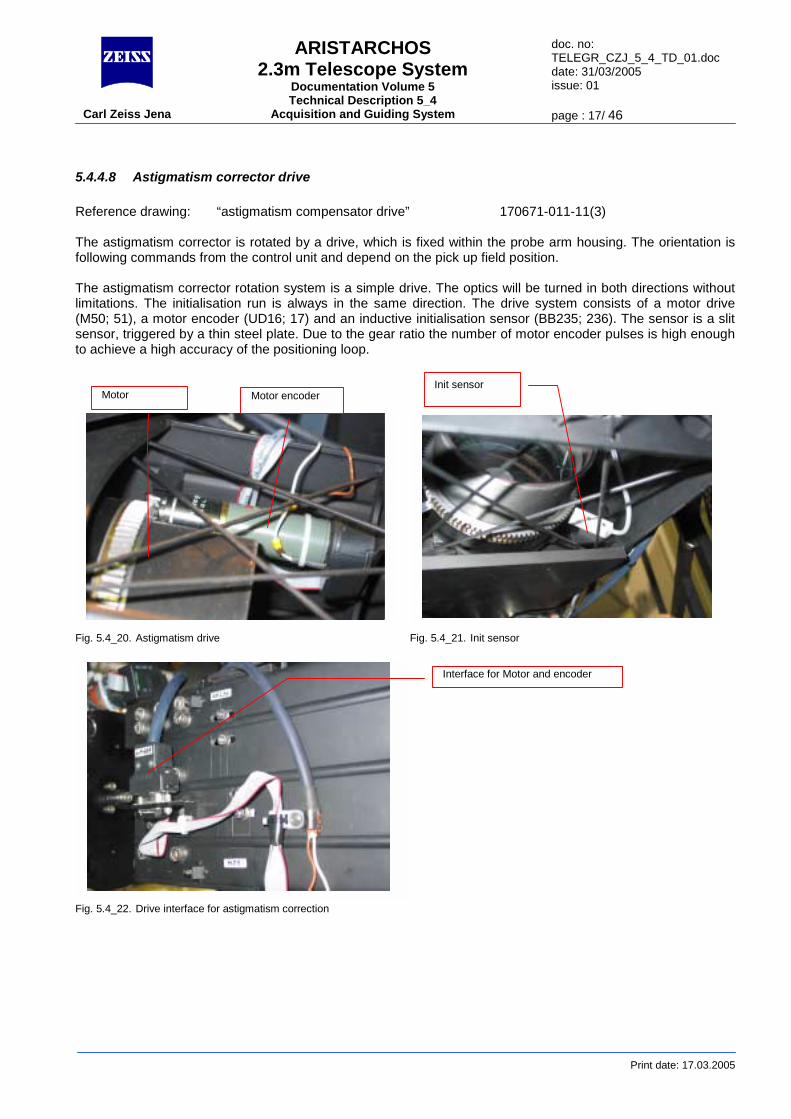
5.4.4.8 Astigmatism corrector drive Reference drawing: “astigmatism compensator drive” 170671-011-11(3) The astigmatism corrector is rotated by a drive, which is fixed within the probe arm housing. The orientation is following commands from the control unit and depend on the pick up field position. The astigmatism corrector rotation system is a simple drive. The optics will be turned in both directions without limitations. The initialisation run is always in the same direction. The drive system consists of a motor drive (M50; 51), a motor encoder (UD16; 17) and an inductive initialisation sensor (BB235; 236). The sensor is a slit sensor, triggered by a thin steel plate. Due to the gear ratio the number of motor encoder pulses is high enough to achieve a high accuracy of the positioning loop.
F F
Motor Motor encoder Init sensor
Print date: 17.03.2005
ig. 5.4_20. Astigmatism drive Fig. 5.4_21. Init sensor
ig. 5.4_22. Drive interface for astigmatism correction
Interface for Motor and encoder
ARISTARCHOS 2.3m Telescope System
Documentation Volume 5 Technical Description 5_4
doc. no: TELEGR_CZJ_5_4_TD_01.doc date: 31/03/2005 issue: 01
Carl Zeiss Jena Acquisition and Guiding System page : 18/ 46
5.4.4.9 Shortener system Reference drawing: 01 99 04 - 005-13(3) The shortener system consists of a meniscus lens and a back side coated lens (Maksutov System). This system reduces the geometrical distance between the pick up mirror and the focal plane and therefore allows a compact design of the guiding system. The shortener optical elements are assembled in a mount, which is the mechanical base for the astigmatism corrector bearing. The shortener system is reducing the system focal length for the telescope-guider system to 12021.34 mm for system 1 and to 12322.5 mm for system 2.
5.4.4.10 Focus movement Reference drawing: “Fokussierantrieb” 019904-008-11(3) To position the AGS sensor (Sensicam CCD camera) to the place with the optimum focus, a linear movement is possible within a range of ±13 mm. The camera is moving together with the filter wheel.
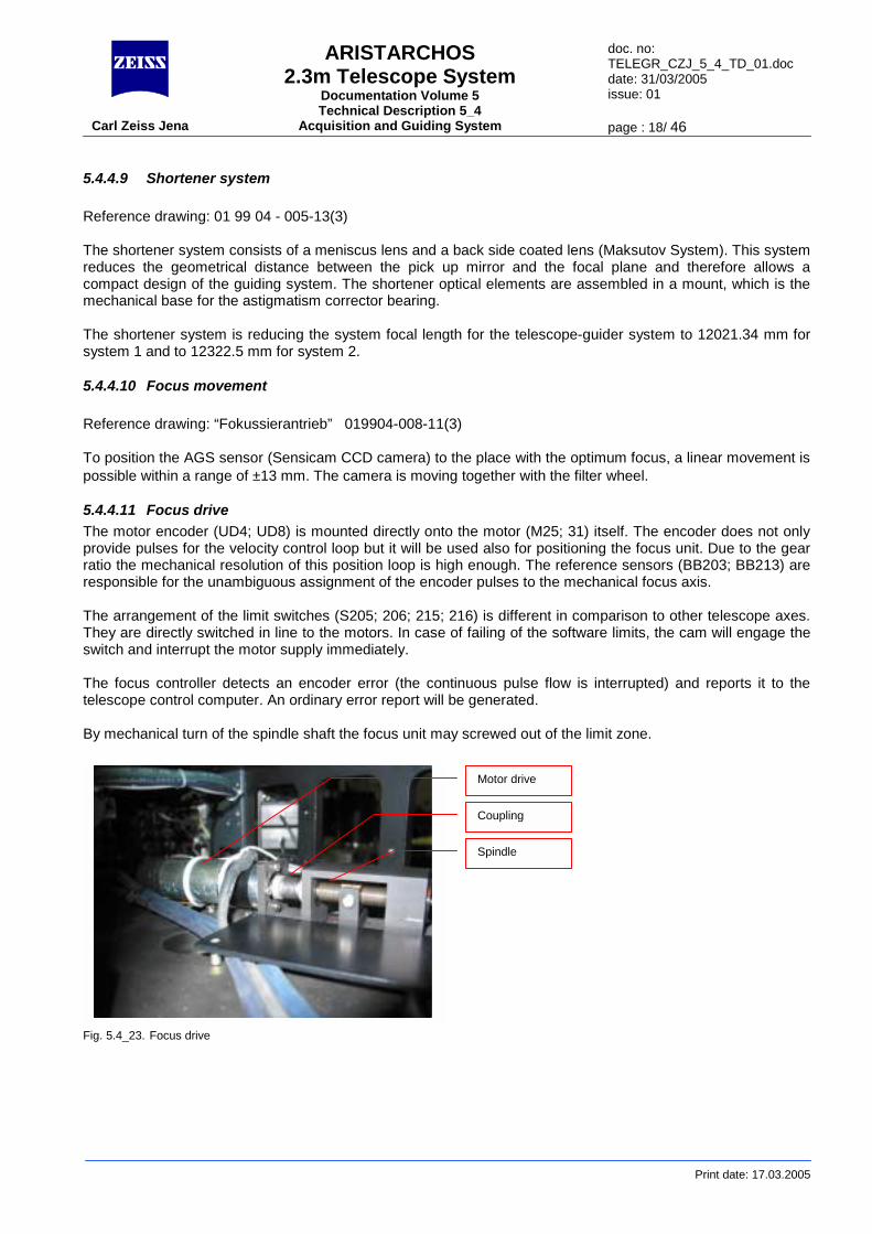
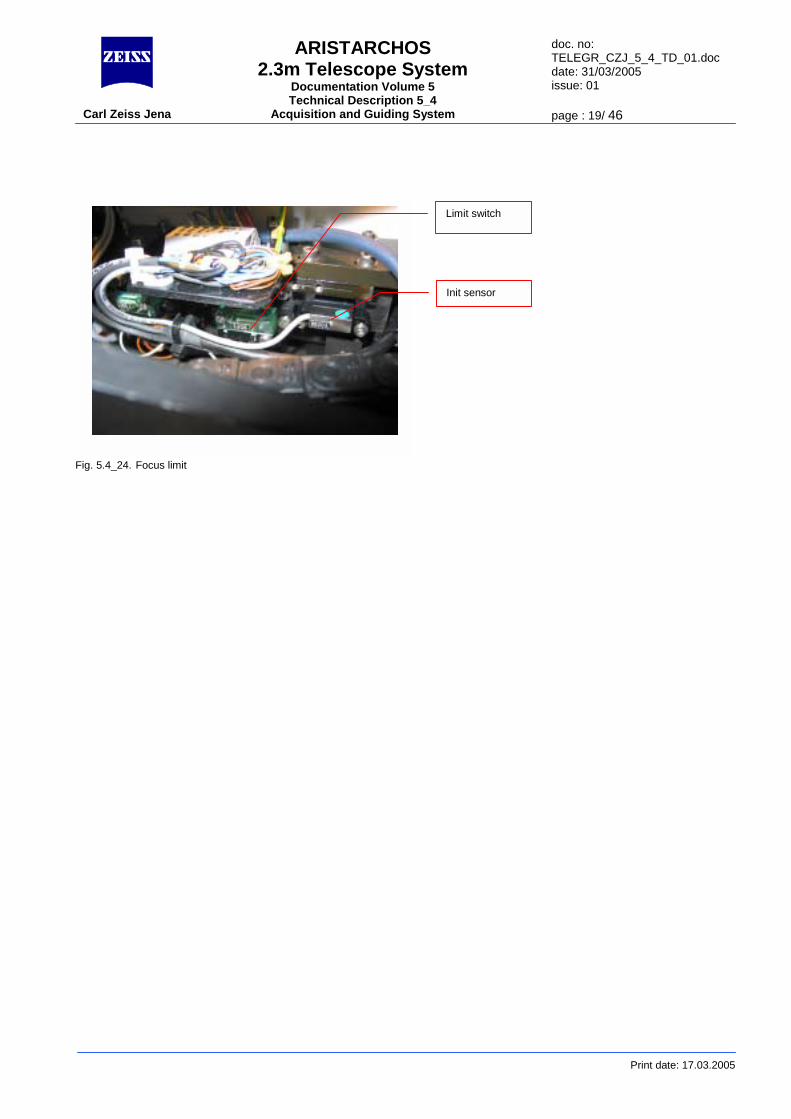
5.4.4.11 Focus drive The motor encoder (UD4; UD8) is mounted directly onto the motor (M25; 31) itself. The encoder does not only provide pulses for the velocity control loop but it will be used also for positioning the focus unit. Due to the gear ratio the mechanical resolution of this position loop is high enough. The reference sensors (BB203; BB213) are responsible for the unambiguous assignment of the encoder pulses to the mechanical focus axis. The arrangement of the limit switches (S205; 206; 215; 216) is different in comparison to other telescope axes. They are directly switched in line to the motors. In case of failing of the software limits, the cam will engage the switch and interrupt the motor supply immediately. The focus controller detects an encoder error (the continuous pulse flow is interrupted) and reports it to the telescope control computer. An ordinary error report will be generated. By mechanical turn of the spindle shaft the focus unit may screwed out of the limit zone. F
Motor drive
Print date: 17.03.2005
ig. 5.4_23. Focus drive
Coupling
Spindle
ARISTARCHOS 2.3m Telescope System
Documentation Volume 5 Technical Description 5_4
doc. no: TELEGR_CZJ_5_4_TD_01.doc date: 31/03/2005 issue: 01
Carl Zeiss Jena Acquisition and Guiding System page : 19/ 46
Print date: 17.03.2005
Fig. 5.4_24. Focus limit
Limit switch
Init sensor
ARISTARCHOS 2.3m Telescope System
Documentation Volume 5 Technical Description 5_4
doc. no: TELEGR_CZJ_5_4_TD_01.doc date: 31/03/2005 issue: 01
Carl Zeiss Jena Acquisition and Guiding System page : 20/ 46
Print date: 17.03.2005
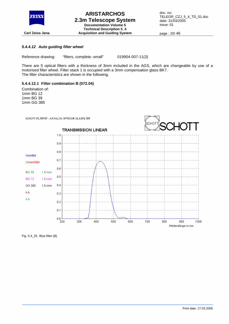
5.4.4.12 Auto guiding filter wheel Reference drawing: “filters, complete.-small” 019904-007-11(3) There are 5 optical filters with a thickness of 3mm included in the AGS, which are changeable by use of a motorised filter wheel. Filter stack 1 is occupied with a 3mm compensation glass BK7. The filter characteristics are shown in the following.
5.4.4.12.1 Filter combination B (072.04) Combination of: 1mm BG 12 1mm BG 39 1mm GG 385
Fig. 5.4_25. Blue filter (B)
ARISTARCHOS 2.3m Telescope System
Documentation Volume 5 Technical Description 5_4
doc. no: TELEGR_CZJ_5_4_TD_01.doc date: 31/03/2005 issue: 01
Carl Zeiss Jena Acquisition and Guiding System page : 21/ 46
Print date: 17.03.2005
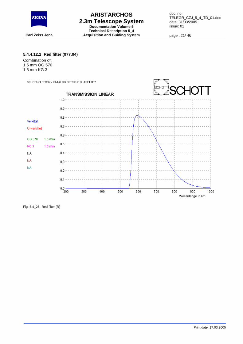
5.4.4.12.2 Red filter (077.04) Combination of: 1.5 mm OG 570 1.5 mm KG 3
Fig. 5.4_26. Red filter (R)
ARISTARCHOS 2.3m Telescope System
Documentation Volume 5 Technical Description 5_4
doc. no: TELEGR_CZJ_5_4_TD_01.doc date: 31/03/2005 issue: 01
Carl Zeiss Jena Acquisition and Guiding System page : 22/ 46
Print date: 17.03.2005
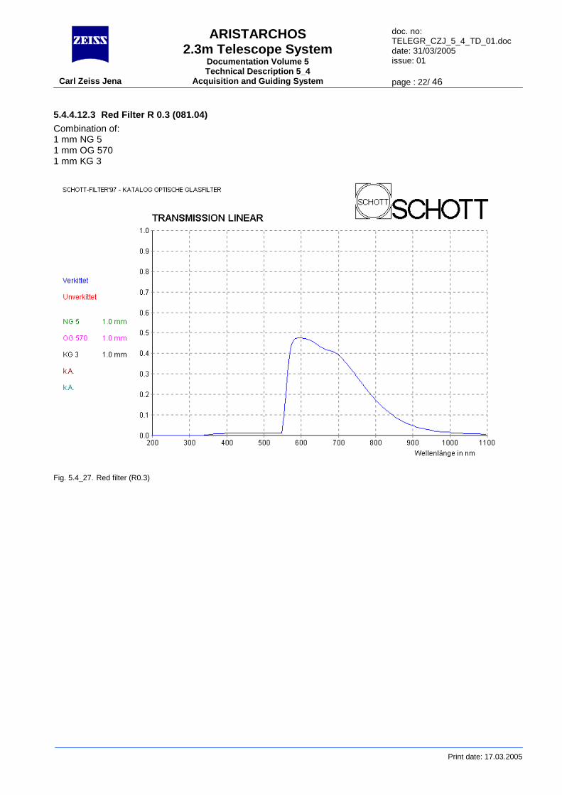
5.4.4.12.3 Red Filter R 0.3 (081.04) Combination of: 1 mm NG 5 1 mm OG 570 1 mm KG 3
Fig. 5.4_27. Red filter (R0.3)

ARISTARCHOS 2.3m Telescope System
Documentation Volume 5 Technical Description 5_4
doc. no: TELEGR_CZJ_5_4_TD_01.doc date: 31/03/2005 issue: 01
Carl Zeiss Jena Acquisition and Guiding System page : 23/ 46
Print date: 17.03.2005
5.4.4.12.4 Filter V (075.04) Combination of: 1.5 mm BG 39 1.5 mm GG 495
Fig. 5.4_28. Green filter (V)
ARISTARCHOS 2.3m Telescope System
Documentation Volume 5 Technical Description 5_4
doc. no: TELEGR_CZJ_5_4_TD_01.doc date: 31/03/2005 issue: 01
Carl Zeiss Jena Acquisition and Guiding System page : 24/ 46
Print date: 17.03.2005
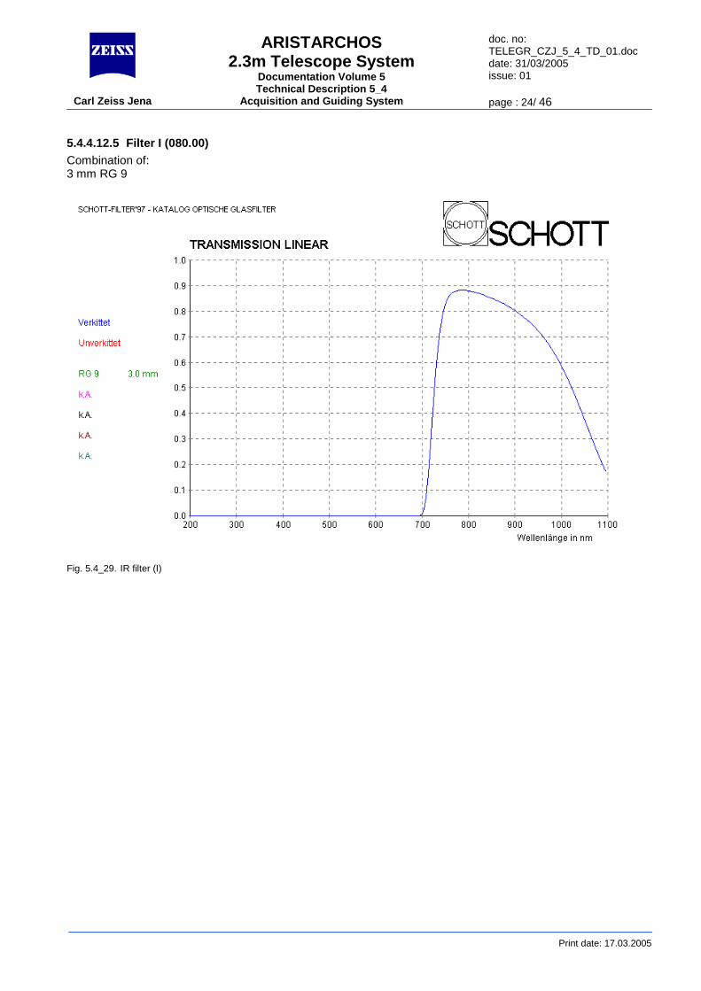
5.4.4.12.5 Filter I (080.00) Combination of: 3 mm RG 9
Fig. 5.4_29. IR filter (I)
ARISTARCHOS 2.3m Telescope System
Documentation Volume 5 Technical Description 5_4
doc. no: TELEGR_CZJ_5_4_TD_01.doc date: 31/03/2005 issue: 01
Carl Zeiss Jena Acquisition and Guiding System page : 25/ 46
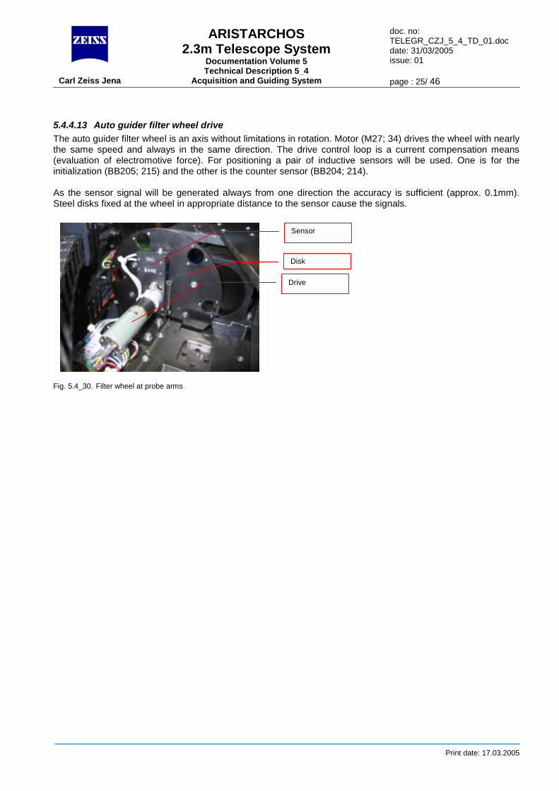
5.4.4.13 Auto guider filter wheel drive The auto guider filter wheel is an axis without limitations in rotation. Motor (M27; 34) drives the wheel with nearly the same speed and always in the same direction. The drive control loop is a current compensation means (evaluation of electromotive force). For positioning a pair of inductive sensors will be used. One is for the initialization (BB205; 215) and the other is the counter sensor (BB204; 214). As the sensor signal will be generated always from one direction the accuracy is sufficient (approx. 0.1mm). Steel disks fixed at the wheel in appropriate distance to the sensor cause the signals. F
sensors
Sensor
Print date: 17.03.2005
ig. 5.4_30. Filter wheel at probe arms
Disk
Drive
ARISTARCHOS 2.3m Telescope System
Documentation Volume 5 Technical Description 5_4
doc. no: TELEGR_CZJ_5_4_TD_01.doc date: 31/03/2005 issue: 01
Carl Zeiss Jena Acquisition and Guiding System page : 26/ 46
Print date: 17.03.2005
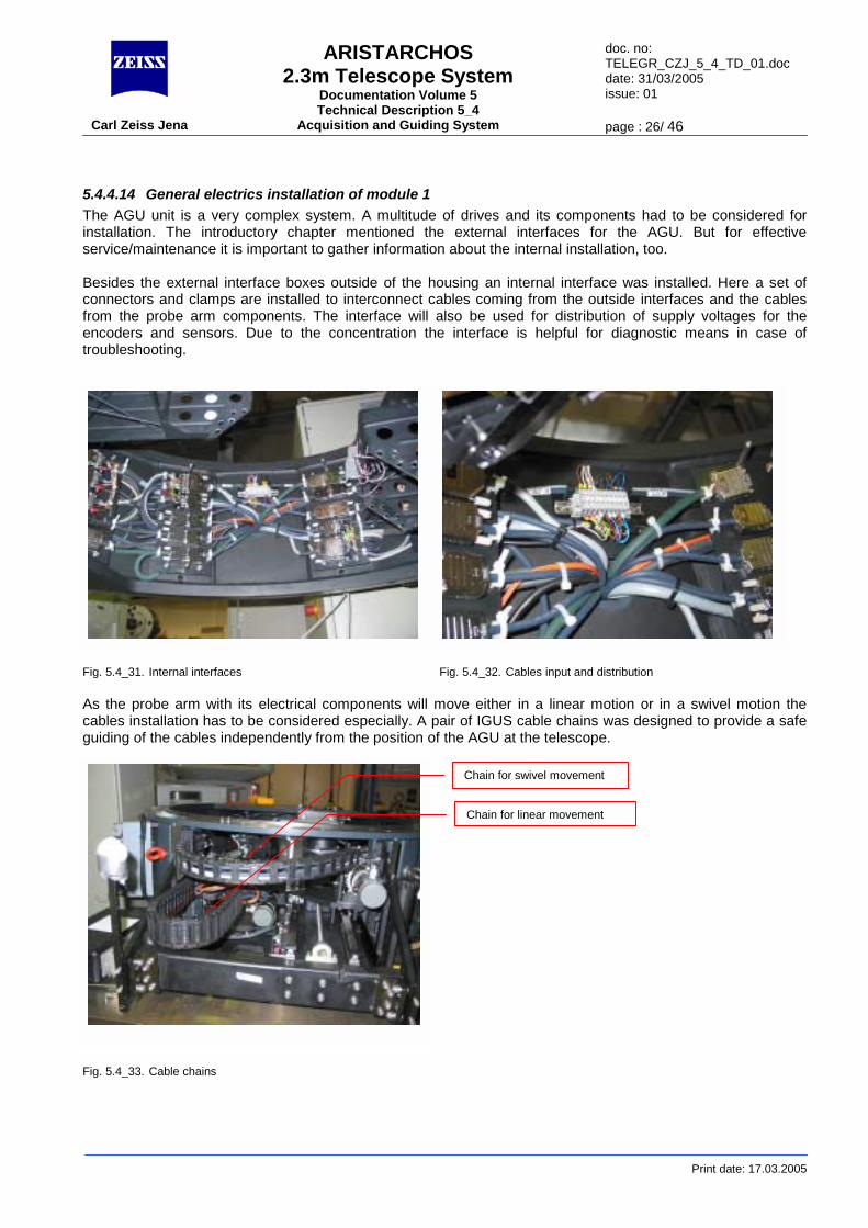
5.4.4.14 General electrics installation of module 1 The AGU unit is a very complex system. A multitude of drives and its components had to be considered for installation. The introductory chapter mentioned the external interfaces for the AGU. But for effective service/maintenance it is important to gather information about the internal installation, too. Besides the external interface boxes outside of the housing an internal interface was installed. Here a set of connectors and clamps are installed to interconnect cables coming from the outside interfaces and the cables from the probe arm components. The interface will also be used for distribution of supply voltages for the encoders and sensors. Due to the concentration the interface is helpful for diagnostic means in case of troubleshooting.
Fig. 5.4_31. Internal interfaces Fig. 5.4_32. Cables input and distribution As the probe arm with its electrical components will move either in a linear motion or in a swivel motion the cables installation has to be considered especially. A pair of IGUS cable chains was designed to provide a safe guiding of the cables independently from the position of the AGU at the telescope.
Fig. 5.4_33. Cable chains
Chain for swivel movement
Chain for linear movement
ARISTARCHOS 2.3m Telescope System
Documentation Volume 5 Technical Description 5_4
doc. no: TELEGR_CZJ_5_4_TD_01.doc date: 31/03/2005 issue: 01
Carl Zeiss Jena Acquisition and Guiding System page : 27/ 46
Print date: 17.03.2005
5.4.5 Module 2 with science fold mirror and rotator Reference drawings: 019904:002.25(0) Bl 1
019904:002.25(0) Bl 2 019904:002.25(0) Bl 3
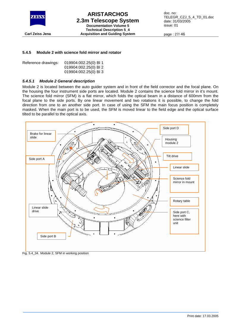
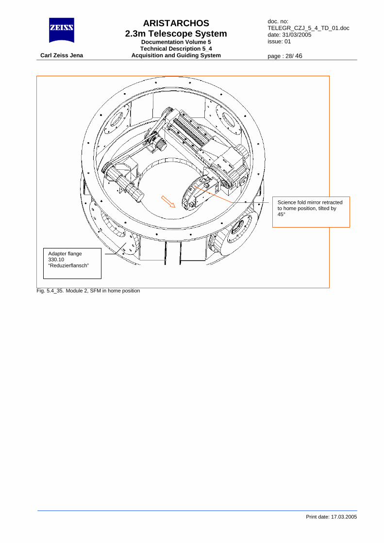
5.4.5.1 Module 2 General description Module 2 is located between the auto guider system and in front of the field corrector and the focal plane. On the housing the four instrument side ports are located. Module 2 contains the science fold mirror in it’s mount. The science fold mirror (SFM) is a flat mirror, which folds the optical beam in a distance of 600mm from the focal plane to the side ports. By one linear movement and two rotations it is possible, to change the fold direction from one to an another side port. In case of using the SFM the main focus position is completely masked. When the main port is to be used, the SFM is moved linear to the field edge and the optical surface tilted to be parallel to the optical axis.
Fig. 5.4_34. Module 2, SFM in working position
Housing module 2
Rotary table
Linear slide
Science fold mirror in mount
Side port D
Side port C, here with science filter unit
Side port B
Side port A
Linear slide drive
Brake for linear slide
Tilt drive
ARISTARCHOS 2.3m Telescope System
Documentation Volume 5 Technical Description 5_4
doc. no: TELEGR_CZJ_5_4_TD_01.doc date: 31/03/2005 issue: 01
Carl Zeiss Jena Acquisition and Guiding System page : 28/ 46
Print date: 17.03.2005
Fig. 5.4_35. Module 2, SFM in home position
Science fold mirror retracted to home position, tilted by 45°
Adapter flange 330.10 “Reduzierflansch”
ARISTARCHOS 2.3m Telescope System
Documentation Volume 5 Technical Description 5_4
doc. no: TELEGR_CZJ_5_4_TD_01.doc date: 31/03/2005 issue: 01
Carl Zeiss Jena Acquisition and Guiding System page : 29/ 46
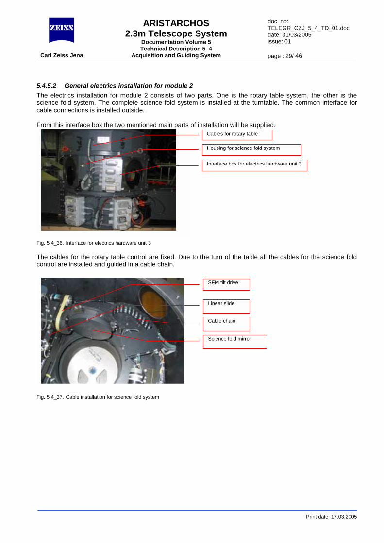
5.4.5.2 General electrics installation for module 2 The electrics installation for module 2 consists of two parts. One is the rotary table system, the other is the science fold system. The complete science fold system is installed at the turntable. The common interface for cable connections is installed outside. From this interface box the two mentioned main parts of installation will be supplied. Fig. 5.4_36. Interface for electrics hardware unit 3 The cables for the rotary table control are fixed. Due to the turn of the table all the cables for the science fold control are installed and guided in a cable chain. F
Cables for rotary table
Housing for science fold system
Interface box for electrics hardware unit 3
SFM tilt drive
Print date: 17.03.2005
ig. 5.4_37. Cable installation for science fold system
Linear slide
Cable chain
Science fold mirror
ARISTARCHOS 2.3m Telescope System
Documentation Volume 5 Technical Description 5_4
doc. no: TELEGR_CZJ_5_4_TD_01.doc date: 31/03/2005 issue: 01
Carl Zeiss Jena Acquisition and Guiding System page : 30/ 46
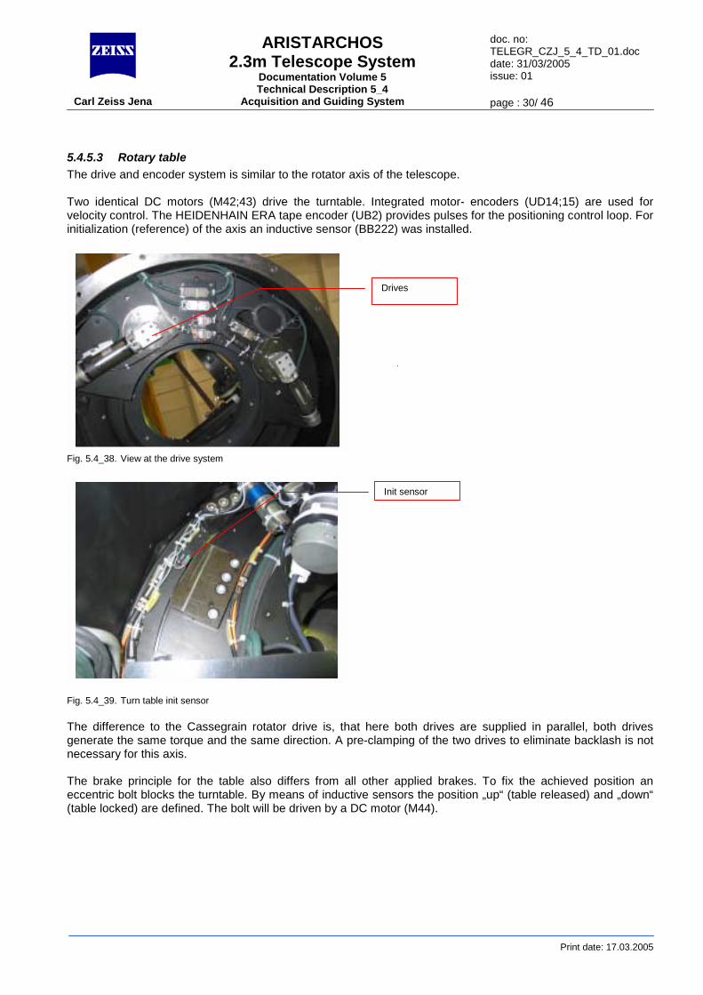
5.4.5.3 Rotary table The drive and encoder system is similar to the rotator axis of the telescope. Two identical DC motors (M42;43) drive the turntable. Integrated motor- encoders (UD14;15) are used for velocity control. The HEIDENHAIN ERA tape encoder (UB2) provides pulses for the positioning control loop. For initialization (reference) of the axis an inductive sensor (BB222) was installed. F F Tgn Te(
Print date: 17.03.2005
ig. 5.4_38. View at the drive system
ig. 5.4_39. Turn table init sensor
he difference to the Cassegrain rotator drive is, that here both drives are supplied in parallel, both drives enerate the same torque and the same direction. A pre-clamping of the two drives to eliminate backlash is not ecessary for this axis.
he brake principle for the table also differs from all other applied brakes. To fix the achieved position an ccentric bolt blocks the turntable. By means of inductive sensors the position „up“ (table released) and „down“ table locked) are defined. The bolt will be driven by a DC motor (M44).
Drives
Init sensor
ARISTARCHOS 2.3m Telescope System
Documentation Volume 5 Technical Description 5_4
doc. no: TELEGR_CZJ_5_4_TD_01.doc date: 31/03/2005 issue: 01
Carl Zeiss Jena Acquisition and Guiding System page : 31/ 46
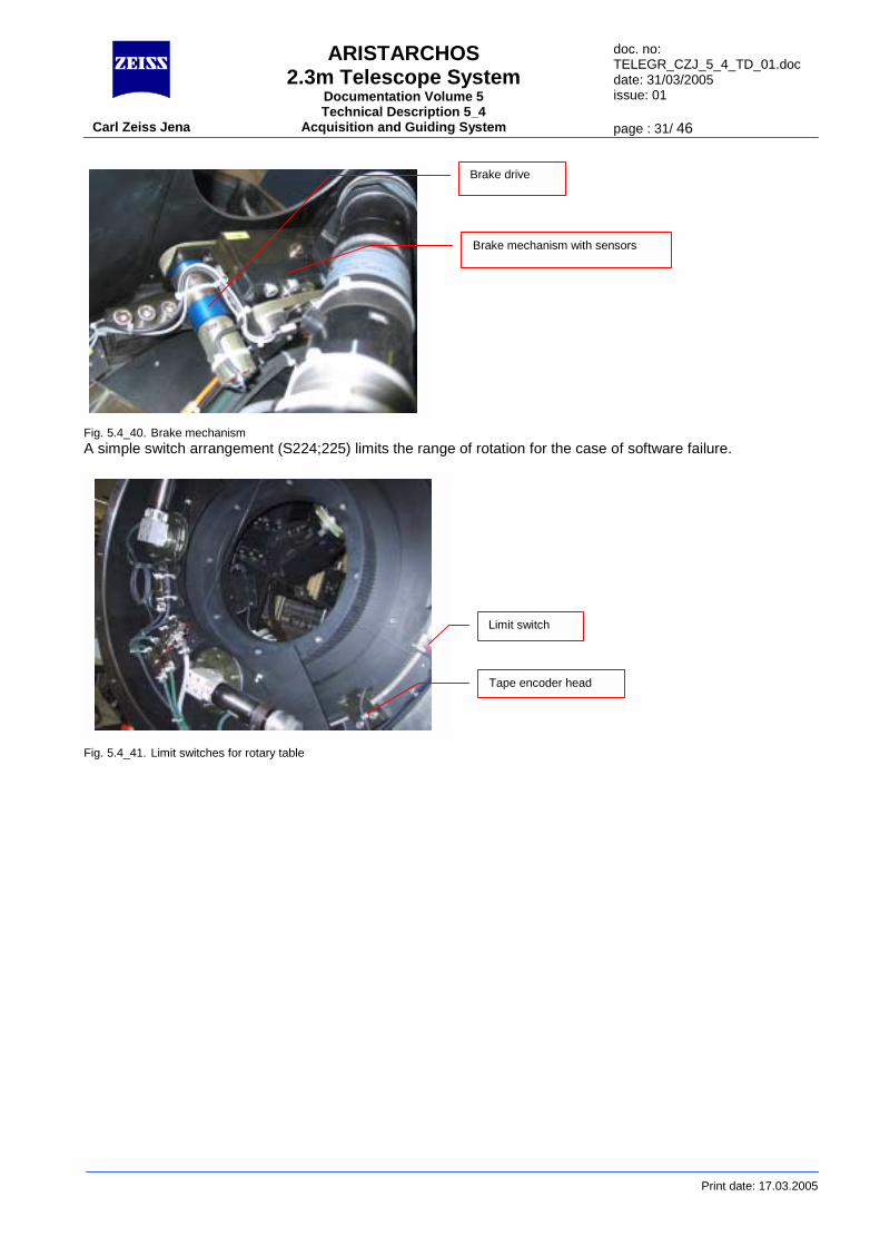
Brake drive
Print date: 17.03.2005
Fig. 5.4_40. Brake mechanism A simple switch arrangement (S224;225) limits the range of rotation for the case of software failure. Fig. 5.4_41. Limit switches for rotary table
Brake mechanism with sensors
Limit switch
Tape encoder head
ARISTARCHOS 2.3m Telescope System
Documentation Volume 5 Technical Description 5_4
doc. no: TELEGR_CZJ_5_4_TD_01.doc date: 31/03/2005 issue: 01
Carl Zeiss Jena Acquisition and Guiding System page : 32/ 46
Print date: 17.03.2005
5.4.5.4 Science fold mirror in mount Reference drawing: 019904:030.11(2) The science fold mirror is made from glass ceramics and has a flat optical surface with an useful area 186x 130 mm (elliptical). It is coated with aluminium with a protective layer of Magnesium fluorite. The mirror is supported in it’s mount on three axial points near the edge. Three safety pads, located on bags in the mirror body, hold the mirror fixed in axial direction. The mirror is fixed in radial direction by three systems, which compensate the difference of the thermal expansion between the metallic mount and the mirror. The mount is directly fixed on the tilt axis.
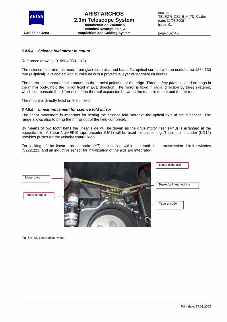
5.4.5.5 Linear movement for science fold mirror The linear movement is important for setting the science fold mirror at the optical axis of the telescope. The range allows also to bring the mirror out of the field completely. By means of two tooth belts the linear slide will be driven as the drive motor itself (M40) is arranged at the opposite site. A linear NUMERIK tape encoder (UA7) will be used for positioning. The motor encoder (UD12) provides pulses for the velocity control loop. For locking of the linear slide a brake (Y7) is installed within the tooth belt transmission. Limit switches (S222;221) and an inductive sensor for initialization of the axis are integrated. Fig. 5.4_42. Linear drive system
Motor encoder
Linear slide axis
Brake for linear locking
Tape encoder
Motor drive
ARISTARCHOS 2.3m Telescope System
Documentation Volume 5 Technical Description 5_4
doc. no: TELEGR_CZJ_5_4_TD_01.doc date: 31/03/2005 issue: 01
Carl Zeiss Jena Acquisition and Guiding System page : 33/ 46
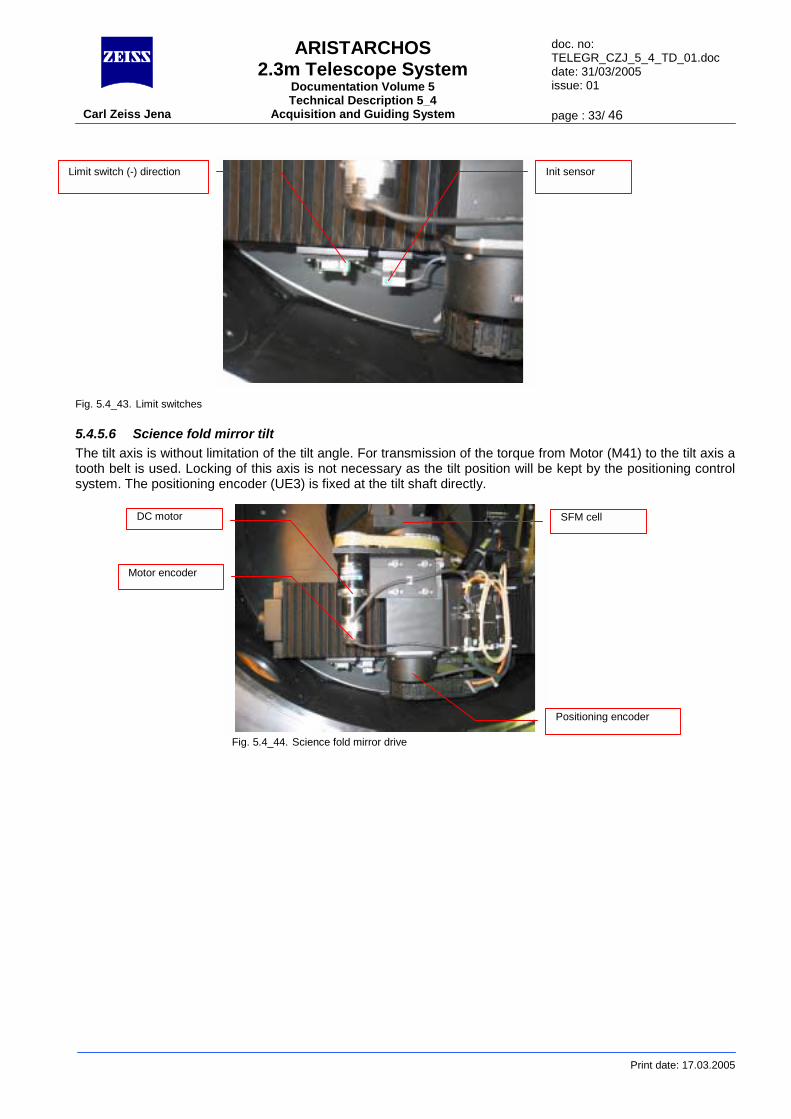
Fig. 5.4_43. Limit switches
5.4.5.6 Science fold The tilt axis is without litooth belt is used. Locksystem. The positioning
Limit switch (-) direction Init sensor
DC motor
Motor encoder
Print date: 17.03.2005
mirror tilt mitation of the tilt angle. For transmission of the torque from Motor (M41) to the tilt axis a ing of this axis is not necessary as the tilt position will be kept by the positioning control encoder (UE3) is fixed at the tilt shaft directly.
Fig. 5.4_44. Science fold mirror drive
SFM cell
Positioning encoder
ARISTARCHOS 2.3m Telescope System
Documentation Volume 5 Technical Description 5_4
doc. no: TELEGR_CZJ_5_4_TD_01.doc date: 31/03/2005 issue: 01
Carl Zeiss Jena Acquisition and Guiding System page : 34/ 46
Print date: 17.03.2005
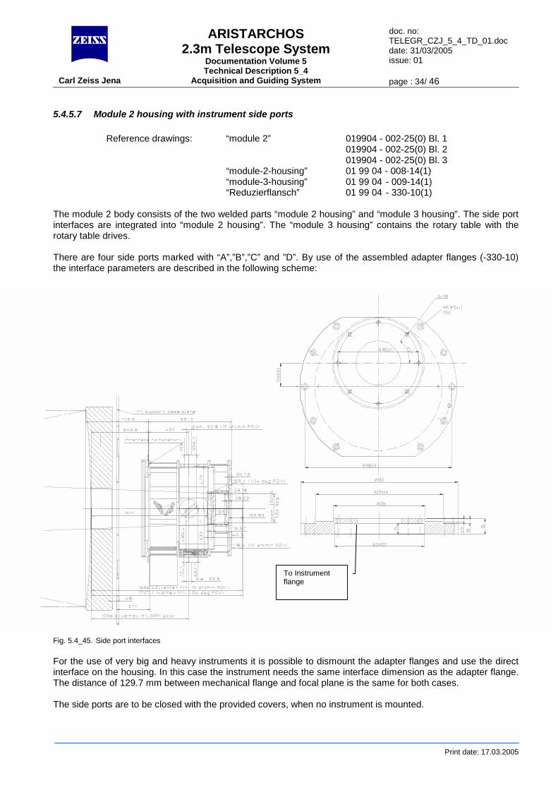
5.4.5.7 Module 2 housing with instrument side ports Reference drawings: “module 2” 019904 - 002-25(0) Bl. 1 019904 - 002-25(0) Bl. 2 019904 - 002-25(0) Bl. 3 “module-2-housing” 01 99 04 - 008-14(1) “module-3-housing” 01 99 04 - 009-14(1) “Reduzierflansch” 01 99 04 - 330-10(1)
The module 2 body consists of the two welded parts “module 2 housing” and “module 3 housing”. The side port interfaces are integrated into “module 2 housing”. The “module 3 housing” contains the rotary table with the rotary table drives. There are four side ports marked with “A”,”B”,”C” and ”D”. By use of the assembled adapter flanges (-330-10) the interface parameters are described in the following scheme:
Fig. 5.4_45. Side port interfaces For the use of very big and heavy instruments it is possible to dismount the adapter flanges and use the direct interface on the housing. In this case the instrument needs the same interface dimension as the adapter flange. The distance of 129.7 mm between mechanical flange and focal plane is the same for both cases. The side ports are to be closed with the provided covers, when no instrument is mounted.
To Instrument flange
ARISTARCHOS 2.3m Telescope System
Documentation Volume 5 Technical Description 5_4
doc. no: TELEGR_CZJ_5_4_TD_01.doc date: 31/03/2005 issue: 01
Carl Zeiss Jena Acquisition and Guiding System page : 35/ 46
Print date: 17.03.2005
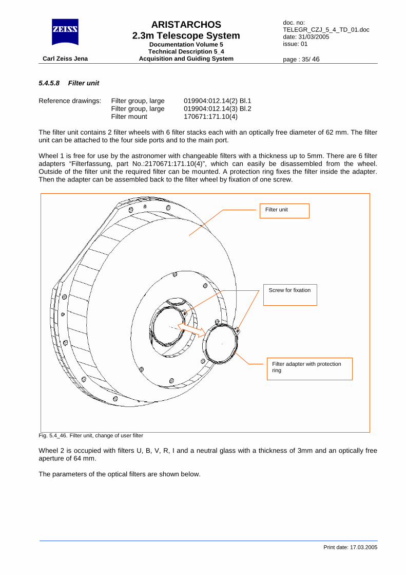
5.4.5.8 Filter unit Reference drawings: Filter group, large 019904:012.14(2) Bl.1
Filter group, large 019904:012.14(3) Bl.2 Filter mount 170671:171.10(4)
The filter unit contains 2 filter wheels with 6 filter stacks each with an optically free diameter of 62 mm. The filter unit can be attached to the four side ports and to the main port. Wheel 1 is free for use by the astronomer with changeable filters with a thickness up to 5mm. There are 6 filter adapters “Filterfassung, part No.:2170671:171.10(4)”, which can easily be disassembled from the wheel. Outside of the filter unit the required filter can be mounted. A protection ring fixes the filter inside the adapter. Then the adapter can be assembled back to the filter wheel by fixation of one screw.
Fig. 5.4_46. Filter unit, change of user filter Wheel 2 is occupied with filters U, B, V, R, I and a neutral glass with a thickness of 3mm and an optically free aperture of 64 mm. The parameters of the optical filters are shown below.
Filter unit
Filter adapter with protection ring
Screw for fixation
ARISTARCHOS 2.3m Telescope System
Documentation Volume 5 Technical Description 5_4
doc. no: TELEGR_CZJ_5_4_TD_01.doc date: 31/03/2005 issue: 01
Carl Zeiss Jena Acquisition and Guiding System page : 36/ 46
Print date: 17.03.2005
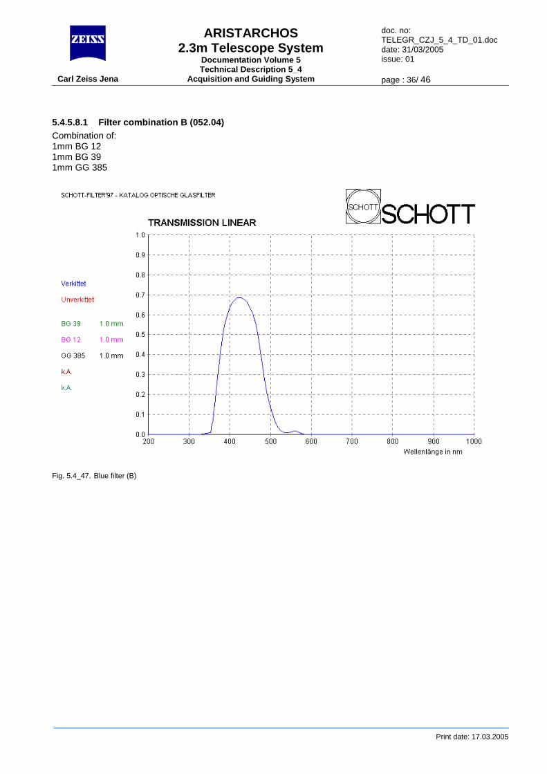
5.4.5.8.1 Filter combination B (052.04) Combination of: 1mm BG 12 1mm BG 39 1mm GG 385
Fig. 5.4_47. Blue filter (B)
ARISTARCHOS 2.3m Telescope System
Documentation Volume 5 Technical Description 5_4
doc. no: TELEGR_CZJ_5_4_TD_01.doc date: 31/03/2005 issue: 01
Carl Zeiss Jena Acquisition and Guiding System page : 37/ 46
Print date: 17.03.2005
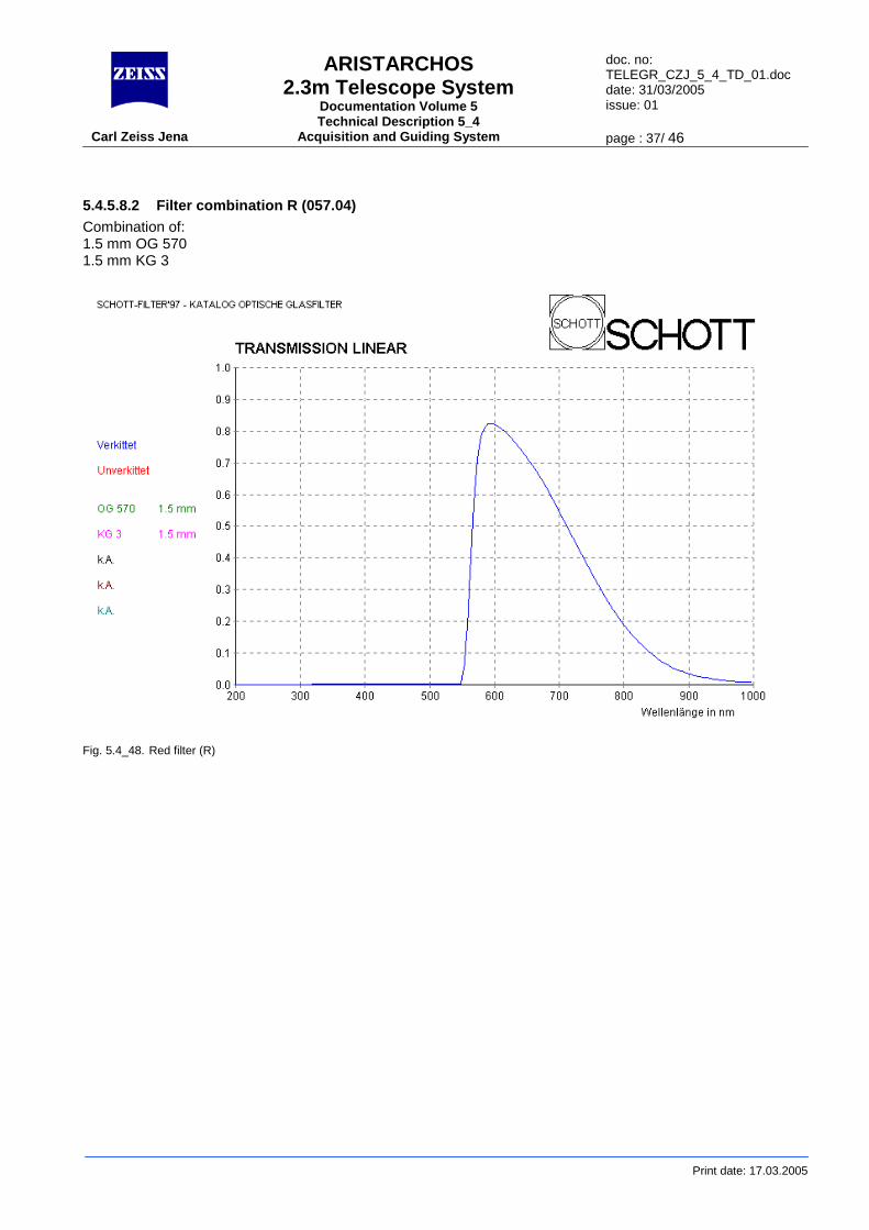
5.4.5.8.2 Filter combination R (057.04) Combination of: 1.5 mm OG 570 1.5 mm KG 3
Fig. 5.4_48. Red filter (R)
ARISTARCHOS 2.3m Telescope System
Documentation Volume 5 Technical Description 5_4
doc. no: TELEGR_CZJ_5_4_TD_01.doc date: 31/03/2005 issue: 01
Carl Zeiss Jena Acquisition and Guiding System page : 38/ 46
Print date: 17.03.2005
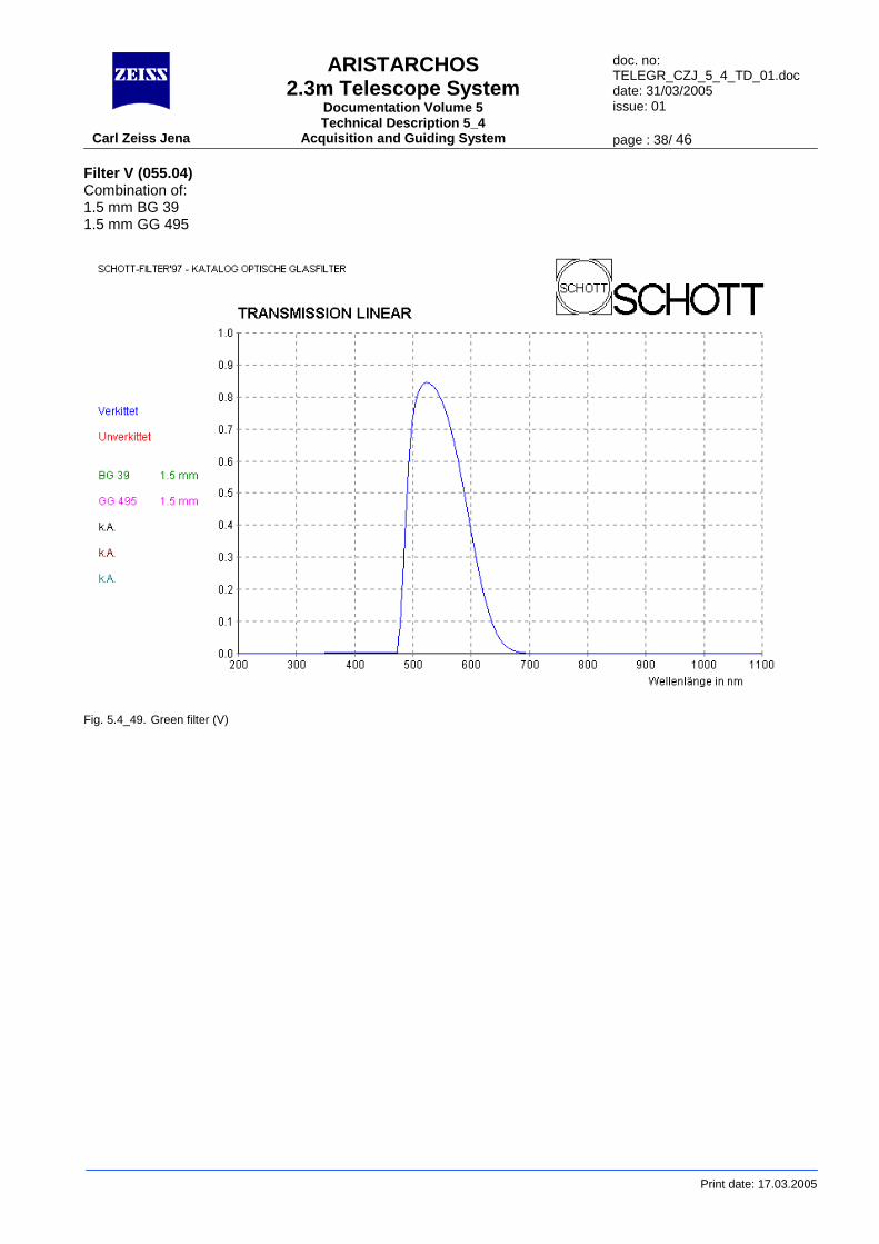
Filter V (055.04) Combination of: 1.5 mm BG 39 1.5 mm GG 495
Fig. 5.4_49. Green filter (V)
ARISTARCHOS 2.3m Telescope System
Documentation Volume 5 Technical Description 5_4
doc. no: TELEGR_CZJ_5_4_TD_01.doc date: 31/03/2005 issue: 01
Carl Zeiss Jena Acquisition and Guiding System page : 39/ 46
Print date: 17.03.2005
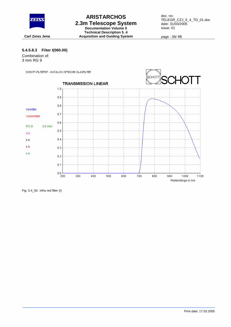
5.4.5.8.3 Filter I(060.00) Combination of: 3 mm RG 9
Fig. 5.4_50. Infra red filter (I)
ARISTARCHOS 2.3m Telescope System
Documentation Volume 5 Technical Description 5_4
doc. no: TELEGR_CZJ_5_4_TD_01.doc date: 31/03/2005 issue: 01
Carl Zeiss Jena Acquisition and Guiding System page : 40/ 46
Print date: 17.03.2005
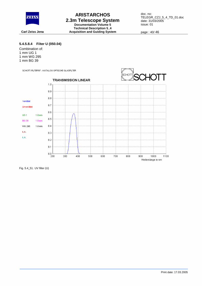
5.4.5.8.4 Filter U (050.04) Combination of: 1 mm UG 1 1 mm WG 295 1 mm BG 39
Fig. 5.4_51. UV filter (U)
ARISTARCHOS 2.3m Telescope System
Documentation Volume 5 Technical Description 5_4
doc. no: TELEGR_CZJ_5_4_TD_01.doc date: 31/03/2005 issue: 01
Carl Zeiss Jena Acquisition and Guiding System page : 41/ 46
Print date: 17.03.2005
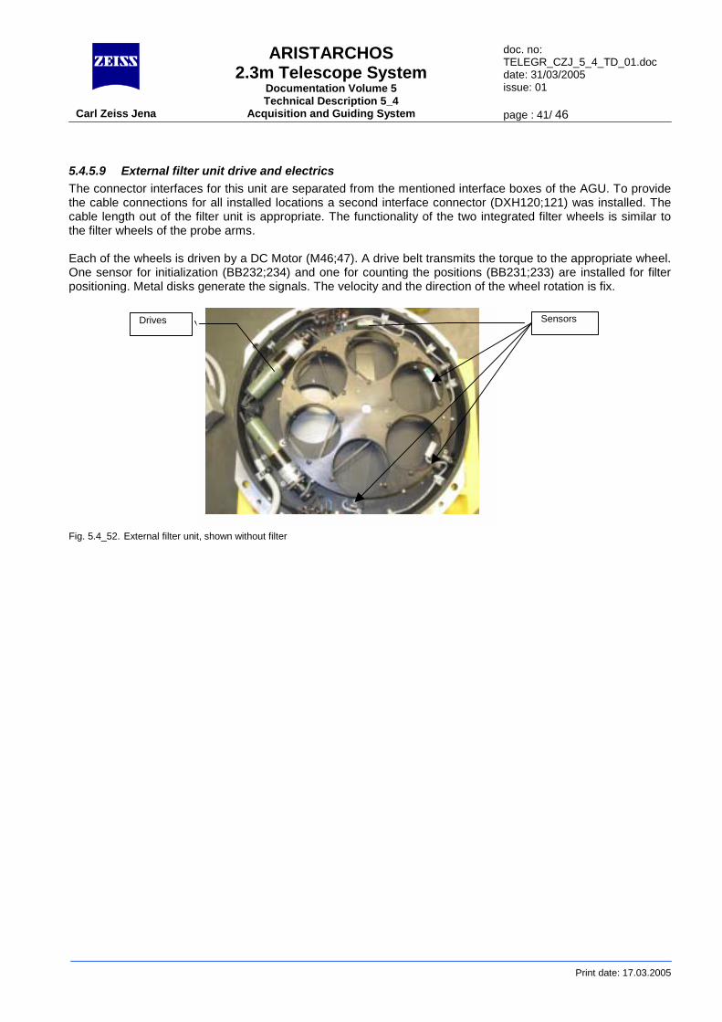
5.4.5.9 External filter unit drive and electrics The connector interfaces for this unit are separated from the mentioned interface boxes of the AGU. To provide the cable connections for all installed locations a second interface connector (DXH120;121) was installed. The cable length out of the filter unit is appropriate. The functionality of the two integrated filter wheels is similar to the filter wheels of the probe arms. Each of the wheels is driven by a DC Motor (M46;47). A drive belt transmits the torque to the appropriate wheel. One sensor for initialization (BB232;234) and one for counting the positions (BB231;233) are installed for filter positioning. Metal disks generate the signals. The velocity and the direction of the wheel rotation is fix. Fig. 5.4_52. External filter unit, shown without filter
Drives Sensors
ARISTARCHOS 2.3m Telescope System
Documentation Volume 5 Technical Description 5_4
doc. no: TELEGR_CZJ_5_4_TD_01.doc date: 31/03/2005 issue: 01
Carl Zeiss Jena Acquisition and Guiding System page : 42/ 46
Print date: 17.03.2005
5.4.6 Module 3 with main port and corrector optics Reference drawings: module 4 housing 019904:010.14(0) Objektiv, gefasst 019904:040.25(3) Filter unit flange 170671:111.10(3) Camera adapter 170671:113.10(3)
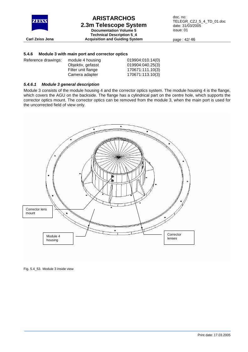
5.4.6.1 Module 3 general description Module 3 consists of the module housing 4 and the corrector optics system. The module housing 4 is the flange, which covers the AGU on the backside. The flange has a cylindrical part on the centre hole, which supports the corrector optics mount. The corrector optics can be removed from the module 3, when the main port is used for the uncorrected field of view only.
Fig. 5.4_53. Module 3 inside view
Module 4 housing
Corrector lenses
Corrector lens mount
ARISTARCHOS 2.3m Telescope System
Documentation Volume 5 Technical Description 5_4
doc. no: TELEGR_CZJ_5_4_TD_01.doc date: 31/03/2005 issue: 01
Carl Zeiss Jena Acquisition and Guiding System page : 43/ 46
Print date: 17.03.2005
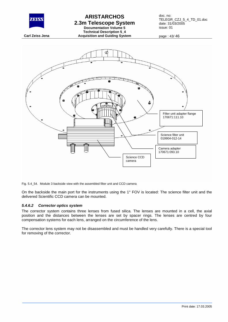
Fig. 5.4_54. Module 3 backside view with the assembled filter unit and CCD camera On the backside the main port for the instruments using the 1° FOV is located: The science filter unit and the delivered Scientific CCD camera can be mounted.
5.4.6.2 Corrector optics system The corrector system contains three lenses from fused silica. The lenses are mounted in a cell, the axial position and the distances between the lenses are set by spacer rings. The lenses are centred by four compensation systems for each lens, arranged on the circumference of the lens. The corrector lens system may not be disassembled and must be handled very carefully. There is a special tool for removing of the corrector.
Science CCD camera
Camera adapter 170671:093.10
Science filter unit 019904-012-14
Filter unit adapter flange 170671:111.10
ARISTARCHOS 2.3m Telescope System
Documentation Volume 5 Technical Description 5_4
doc. no: TELEGR_CZJ_5_4_TD_01.doc date: 31/03/2005 issue: 01
Carl Zeiss Jena Acquisition and Guiding System page : 44/ 46
Print date: 17.03.2005
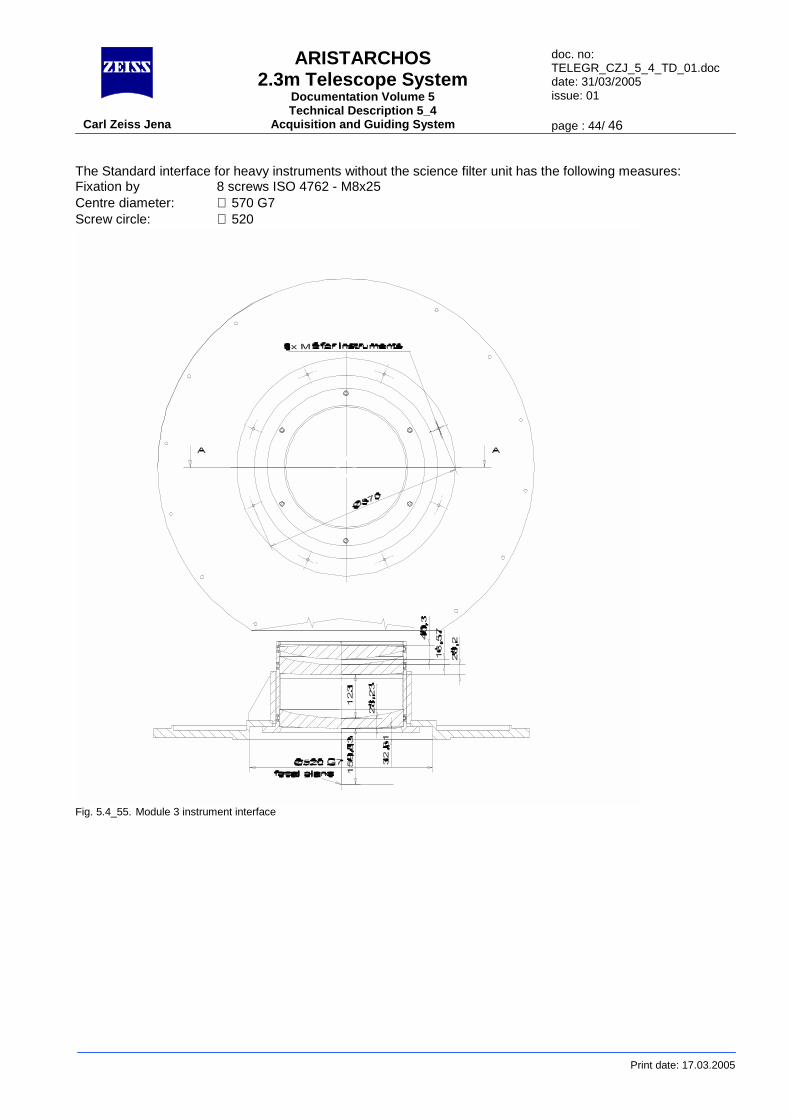
The Standard interface for heavy instruments without the science filter unit has the following measures: Fixation by 8 screws ISO 4762 - M8x25 Centre diameter: ∅ 570 G7 Screw circle: ∅ 520
Fig. 5.4_55. Module 3 instrument interface
ARISTARCHOS 2.3m Telescope System
Documentation Volume 5 Technical Description 5_4
doc. no: TELEGR_CZJ_5_4_TD_01.doc date: 31/03/2005 issue: 01
Carl Zeiss Jena Acquisition and Guiding System page : 45/ 46
Print date: 17.03.2005
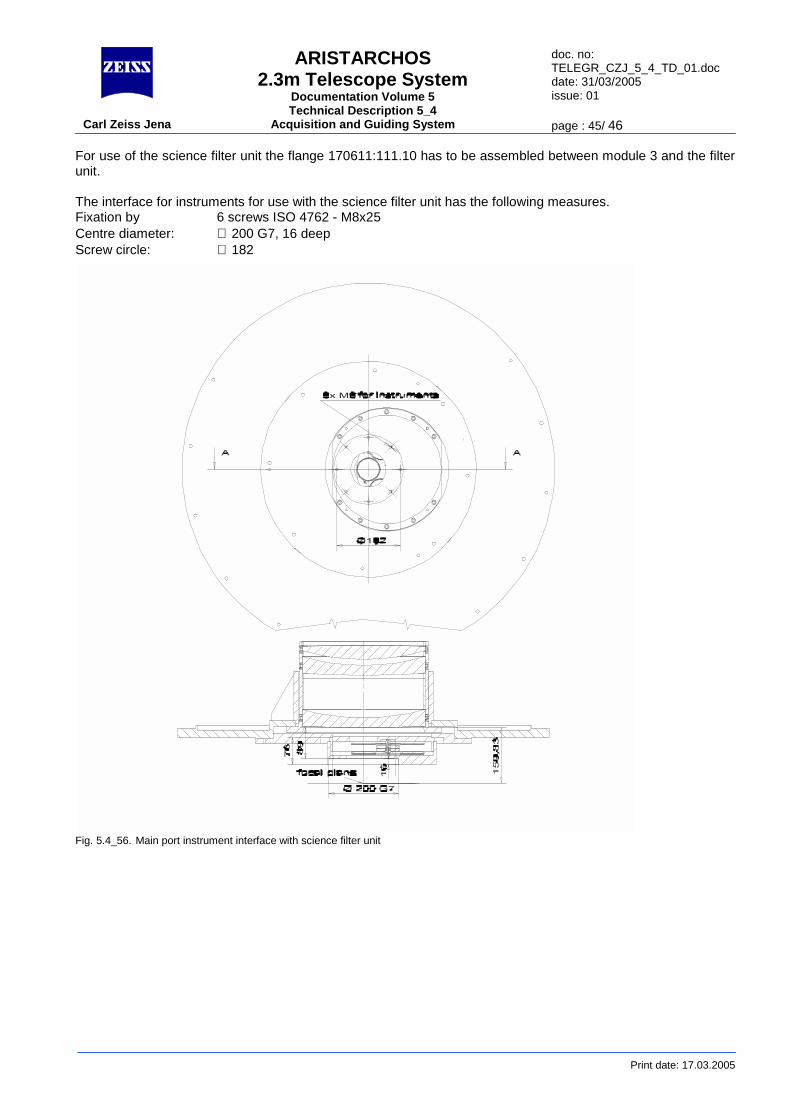
For use of the science filter unit the flange 170611:111.10 has to be assembled between module 3 and the filter unit. The interface for instruments for use with the science filter unit has the following measures. Fixation by 6 screws ISO 4762 - M8x25 Centre diameter: ∅ 200 G7, 16 deep Screw circle: ∅ 182
Fig. 5.4_56. Main port instrument interface with science filter unit
ARISTARCHOS 2.3m Telescope System
Documentation Volume 5 Technical Description 5_4
doc. no: TELEGR_CZJ_5_4_TD_01.doc date: 31/03/2005 issue: 01
Carl Zeiss Jena Acquisition and Guiding System page : 46/ 46
Print date: 17.03.2005
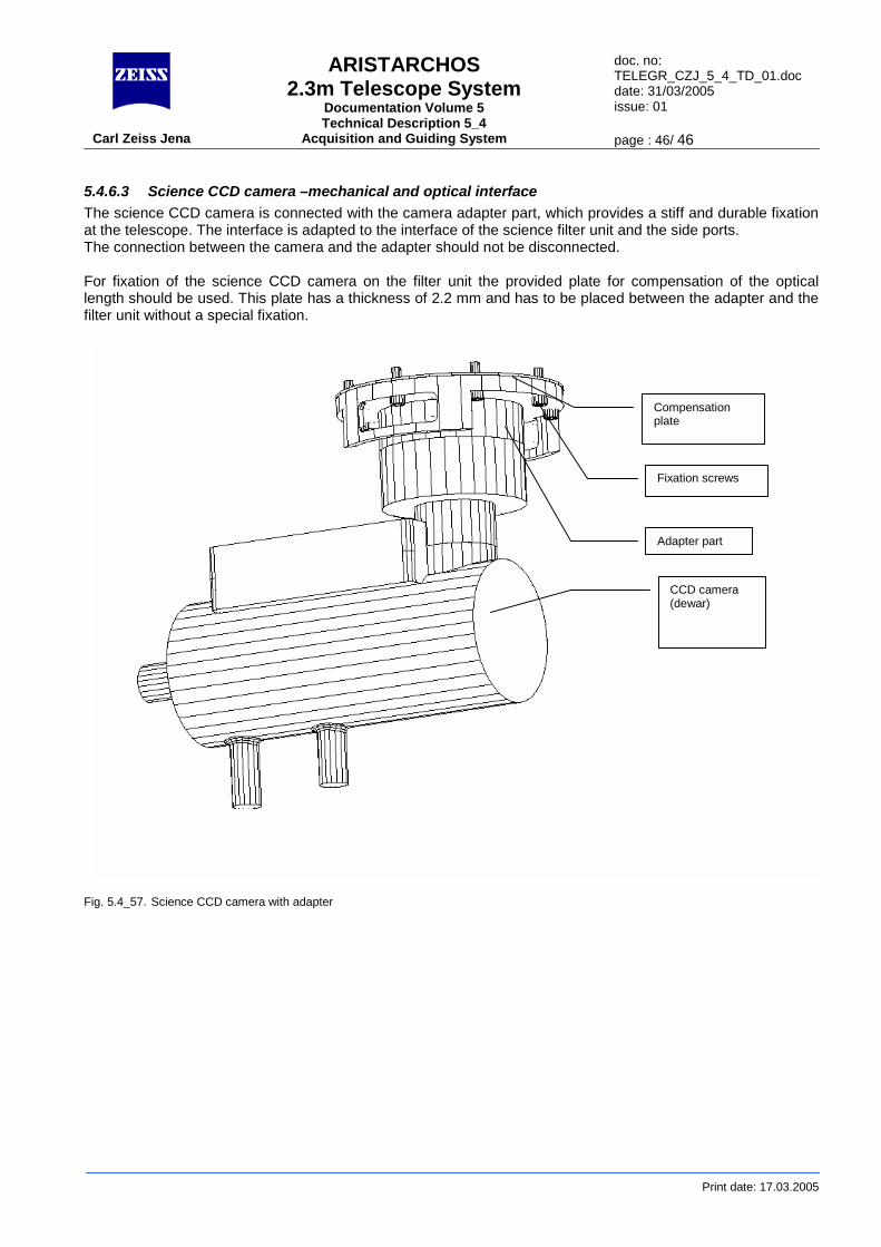
5.4.6.3 Science CCD camera –mechanical and optical interface The science CCD camera is connected with the camera adapter part, which provides a stiff and durable fixation at the telescope. The interface is adapted to the interface of the science filter unit and the side ports. The connection between the camera and the adapter should not be disconnected. For fixation of the science CCD camera on the filter unit the provided plate for compensation of the optical length should be used. This plate has a thickness of 2.2 mm and has to be placed between the adapter and the filter unit without a special fixation.
Fig. 5.4_57. Science CCD camera with adapter
CCD camera (dewar)
Adapter part
Compensation plate
Fixation screws