Technical characteristics of air interfaces for global ... · Technical characteristics of air...
46
Rec. ITU-R S.1709-1 1 RECOMMENDATION ITU-R S.1709-1 Technical characteristics of air interfaces for global broadband satellite systems (Question ITU-R 269/4) (2005-2007) Scope This Recommendation proposes air interface characteristics which can be used as guidance by designers of broadband satellite networks. The substance of the text is divided into four Annexes, the first being a generic description of the network architecture of broadband satellite networks. The remaining Annexes each contain a summary of existing air interface standards that have been approved by various standardization bodies. Annex 2 contains a summary of TIA-1008-A dealing with Internet protocol (IP) over satellite (IPoS). Annex 3 contains a summary of the DVB-RCS standard as described in ETSI Document EN 301 790. Annex 4 contains a summary of the air interface specification for global broadband communications between earth stations and regenerative satellites based on ETSI BSM/RSM-A. The ITU Radiocommunication Assembly, considering a) that satellite telecommunications technology has the potential to accelerate the availability of broadband communications both on a global and regional basis; b) that operational experience with the deployment of broadband satellite networks has demonstrated the practicality and usefulness of these networks; c) that several different types of architectures are used in broadband satellite systems; d) that these varying uses have led to the development of various air interface standards in order to allow seamless transportation of broadband signals over different networks, recommends 1 that when broadband radiocommunications are being designed based on the use of satellites, the generic satellite network architecture and protocol structures defined in Annex 1 may be used; 2 that when broadband radiocommunications are being provided between earth stations and geostationary satellites, the specifications contained in Annexes 2 to 4 may be used.
Transcript of Technical characteristics of air interfaces for global ... · Technical characteristics of air...
Rec. ITU-R S.1709-1 1
RECOMMENDATION ITU-R S.1709-1
Technical characteristics of air interfaces for global broadband satellite systems (Question ITU-R 269/4)
(2005-2007)
Scope
This Recommendation proposes air interface characteristics which can be used as guidance by designers of broadband satellite networks. The substance of the text is divided into four Annexes, the first being a generic description of the network architecture of broadband satellite networks. The remaining Annexes each contain a summary of existing air interface standards that have been approved by various standardization bodies. Annex 2 contains a summary of TIA-1008-A dealing with Internet protocol (IP) over satellite (IPoS). Annex 3 contains a summary of the DVB-RCS standard as described in ETSI Document EN 301 790. Annex 4 contains a summary of the air interface specification for global broadband communications between earth stations and regenerative satellites based on ETSI BSM/RSM-A.
The ITU Radiocommunication Assembly,
considering a) that satellite telecommunications technology has the potential to accelerate the availability of broadband communications both on a global and regional basis;
b) that operational experience with the deployment of broadband satellite networks has demonstrated the practicality and usefulness of these networks;
c) that several different types of architectures are used in broadband satellite systems;
d) that these varying uses have led to the development of various air interface standards in order to allow seamless transportation of broadband signals over different networks,
recommends
1 that when broadband radiocommunications are being designed based on the use of satellites, the generic satellite network architecture and protocol structures defined in Annex 1 may be used;
2 that when broadband radiocommunications are being provided between earth stations and geostationary satellites, the specifications contained in Annexes 2 to 4 may be used.
2 Rec. ITU-R S.1709-1
Annex 1
Generic network architecture for global broadband satellite systems
1 Introduction The inherent characteristics of satellite communications, that is their wide-coverage, broadcast mode of operation and multicasting, make them capable of providing high-speed Internet connection and multimedia long-distance transmissions. There are many possible implementations of broadband by satellite, however, certain fundamental features such as protocol stacks, satellite dependant and independent functions, user-access to the system and air interface are very similar. This Recommendation addresses three distinct standardization efforts as follows: – Telecommunication Industry Association (TIA) IPoS as summarized in Annex 2; – European Telecommunication Standards Institute (ETSI) (2000) DVB, interactive channel
for satellite distribution systems as summarized in Annex 3; – Air interface specifications for global broadband communications between earth stations
and regenerative satellites based on ETSI BSM/RSM-A as summarized in Annex 4.
These three standards as summarized in Table 1 could be applied for high-speed Internet access services either for individual households or collective residential services. Satellite interconnectivity with the terrestrial networks in a seamless fashion is very crucial for the broadband satellite service success. The architectures described in the following sections would provide a guidance to the system designers and the evaluators with respect to the system design and deployment. This Annex describes a global broadband network scenario along with common applications and services. In addition, the normal network topologies such as star and mesh are described. This Annex provides a basis for the remainder of the Recommendation describing the three standards development for broadband satellite networks. Appendix 1 to Annex 1 provides a list of references for all the specifications described in this Recommendation.
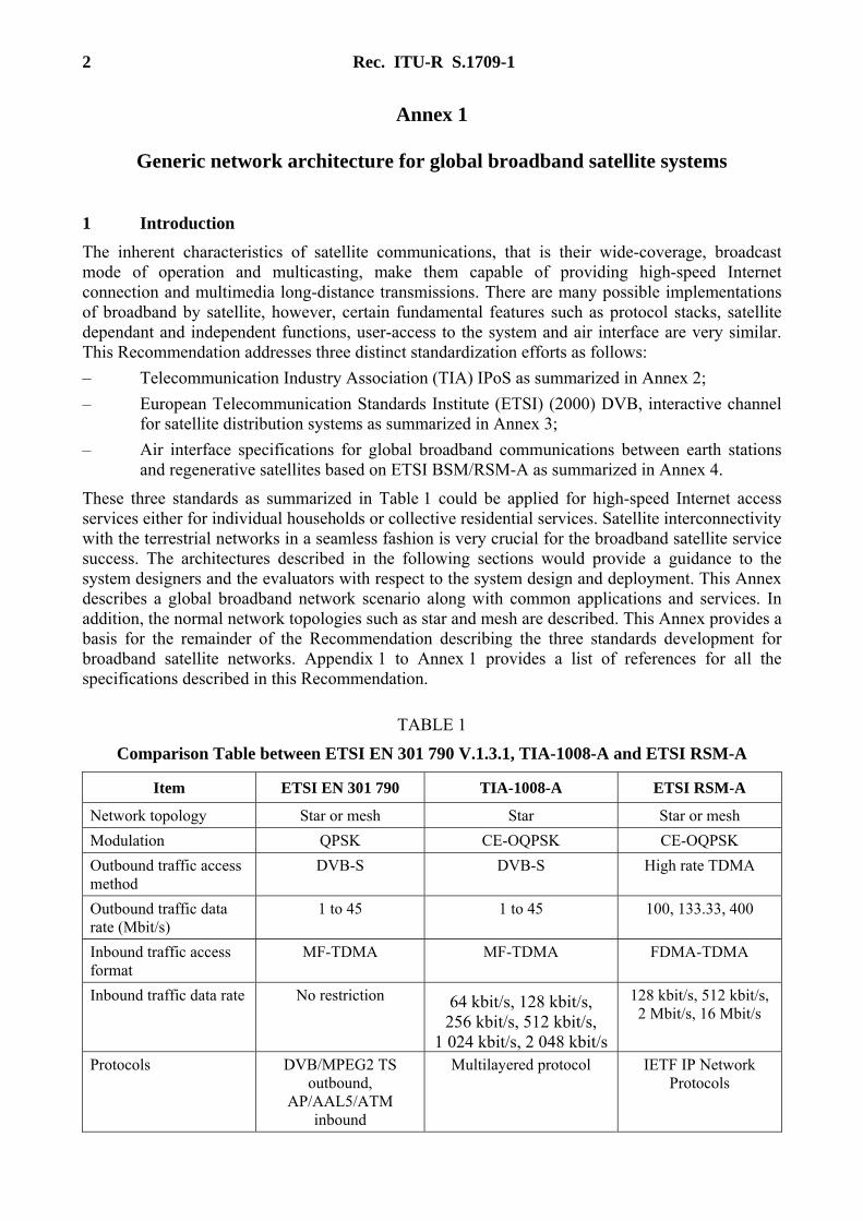
TABLE 1
Comparison Table between ETSI EN 301 790 V.1.3.1, TIA-1008-A and ETSI RSM-A
Item ETSI EN 301 790 TIA-1008-A ETSI RSM-A
Network topology Star or mesh Star Star or mesh Modulation QPSK CE-OQPSK CE-OQPSK Outbound traffic access method
DVB-S DVB-S High rate TDMA
Outbound traffic data rate (Mbit/s)
1 to 45 1 to 45 100, 133.33, 400
Inbound traffic access format
MF-TDMA MF-TDMA FDMA-TDMA
Inbound traffic data rate No restriction 64 kbit/s, 128 kbit/s, 256 kbit/s, 512 kbit/s,
1 024 kbit/s, 2 048 kbit/s
128 kbit/s, 512 kbit/s, 2 Mbit/s, 16 Mbit/s
Protocols DVB/MPEG2 TS outbound,
AP/AAL5/ATM inbound
Multilayered protocol IETF IP Network Protocols
Rec. ITU-R S.1709-1 3
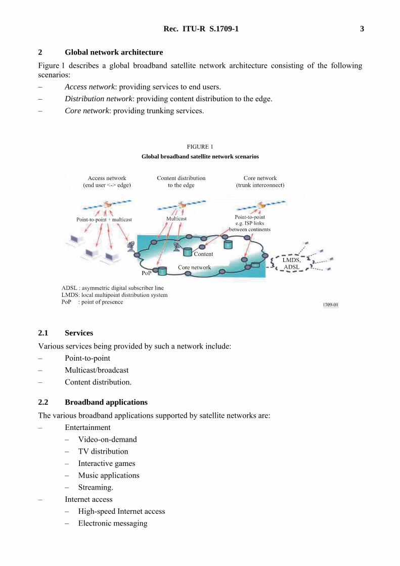
2 Global network architecture Figure 1 describes a global broadband satellite network architecture consisting of the following scenarios: – Access network: providing services to end users. – Distribution network: providing content distribution to the edge. – Core network: providing trunking services.
FIGURE 1 Global broadband satellite network scenarios
2.1 Services
Various services being provided by such a network include: – Point-to-point – Multicast/broadcast – Content distribution.
2.2 Broadband applications The various broadband applications supported by satellite networks are: – Entertainment
– Video-on-demand – TV distribution – Interactive games – Music applications – Streaming.
– Internet access – High-speed Internet access – Electronic messaging
4 Rec. ITU-R S.1709-1
– Multimedia applications – Distance learning – Telemedicine.
– Business – Videoconferencing – Business-to-business – Home security.
– Voice and data trunking – IP-transport – Voice-over-IP – File transfers.
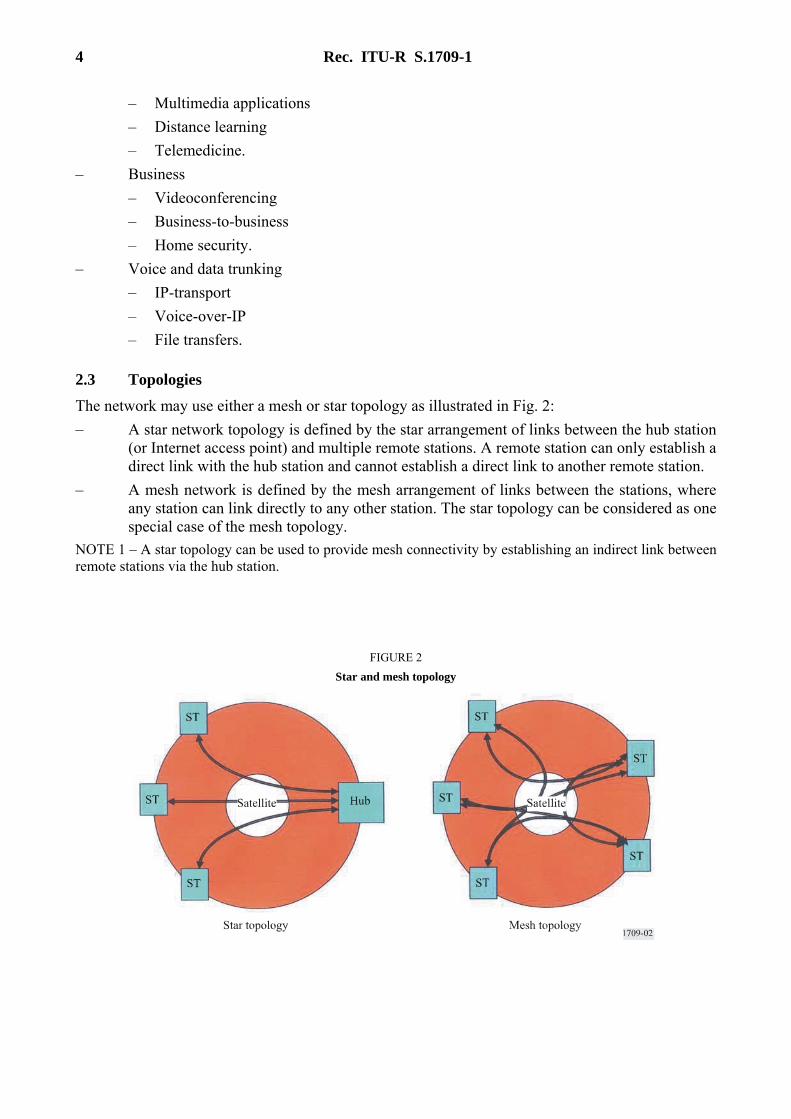
2.3 Topologies The network may use either a mesh or star topology as illustrated in Fig. 2: – A star network topology is defined by the star arrangement of links between the hub station
(or Internet access point) and multiple remote stations. A remote station can only establish a direct link with the hub station and cannot establish a direct link to another remote station.
– A mesh network is defined by the mesh arrangement of links between the stations, where any station can link directly to any other station. The star topology can be considered as one special case of the mesh topology.
NOTE 1 – A star topology can be used to provide mesh connectivity by establishing an indirect link between remote stations via the hub station.
FIGURE 2 Star and mesh topology

Rec. ITU-R S.1709-1 5
A global broadband satellite-system network may use either a non-regenerative or a regenerative satellite architecture: – A non-regenerative architecture refers to a single architecture, commonly called a
“bent-pipe architecture”. This architecture does not terminate any layers of the air interface protocol stack in the satellite – the satellite simply transfers the signals from the user links to the feeder links transparently.
– A regenerative architecture is the range of other architectures that provide additional functionality in the satellite. In these architectures, the satellite functions terminate one or more layers of the air interface protocol stack in the satellite.
2.4 Services architecture Figure 3 illustrates the various services e.g. standard IP services, broadband satellite bearer services, and the underlying radio transmission bearer services. The broadband satellite for multimedia (BSM) working group of ETSI developed a broadband service architecture handling these three types of services.
In order to separate the services that are common to all satellite systems from those that are specific to a given satellite technology, the service architecture defines a satellite-independent service access point (SI-SAP) as the interface between these upper and lower layers. This interface corresponds to the ends of the global broadband satellite system bearer services as shown in Fig. 3.
FIGURE 3 Global broadband satellite service architecture
6 Rec. ITU-R S.1709-1
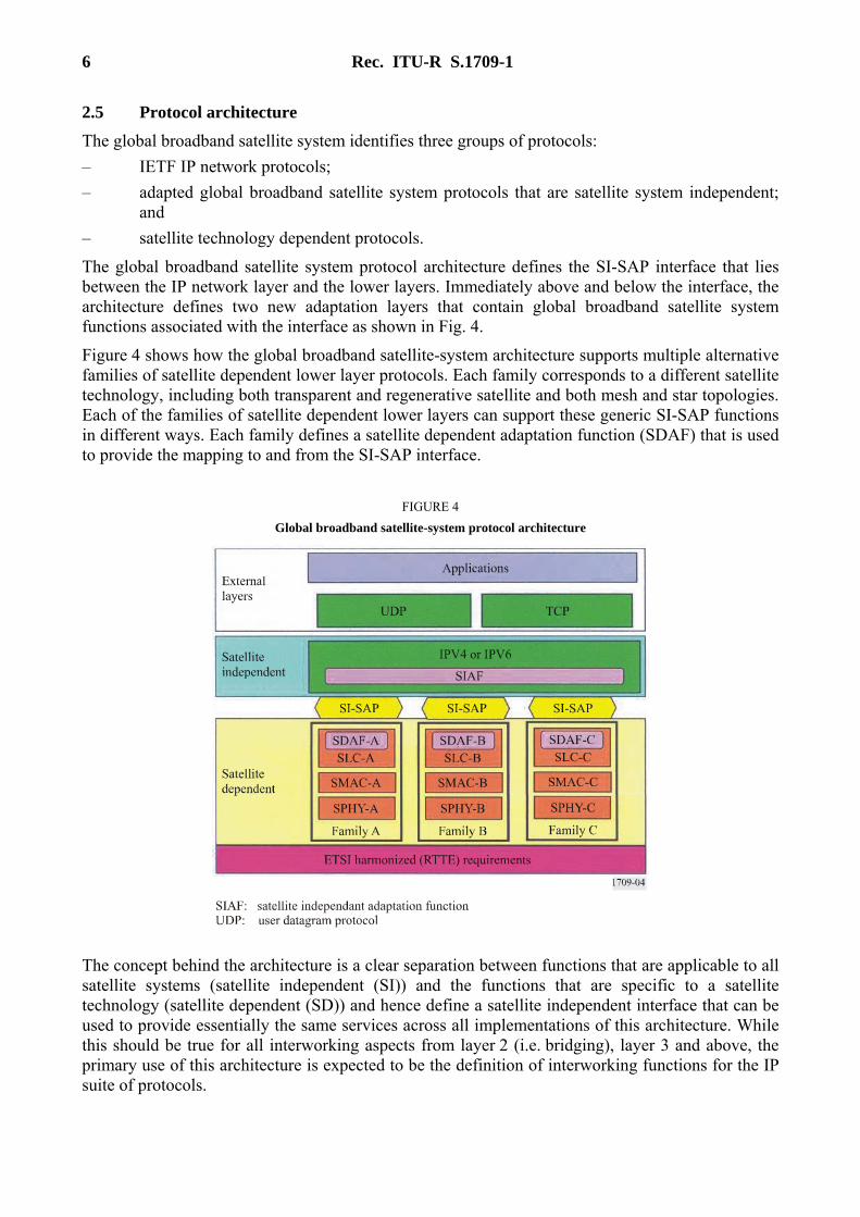
2.5 Protocol architecture The global broadband satellite system identifies three groups of protocols: – IETF IP network protocols; – adapted global broadband satellite system protocols that are satellite system independent;
and – satellite technology dependent protocols.
The global broadband satellite system protocol architecture defines the SI-SAP interface that lies between the IP network layer and the lower layers. Immediately above and below the interface, the architecture defines two new adaptation layers that contain global broadband satellite system functions associated with the interface as shown in Fig. 4.
Figure 4 shows how the global broadband satellite-system architecture supports multiple alternative families of satellite dependent lower layer protocols. Each family corresponds to a different satellite technology, including both transparent and regenerative satellite and both mesh and star topologies. Each of the families of satellite dependent lower layers can support these generic SI-SAP functions in different ways. Each family defines a satellite dependent adaptation function (SDAF) that is used to provide the mapping to and from the SI-SAP interface.
FIGURE 4 Global broadband satellite-system protocol architecture
The concept behind the architecture is a clear separation between functions that are applicable to all satellite systems (satellite independent (SI)) and the functions that are specific to a satellite technology (satellite dependent (SD)) and hence define a satellite independent interface that can be used to provide essentially the same services across all implementations of this architecture. While this should be true for all interworking aspects from layer 2 (i.e. bridging), layer 3 and above, the primary use of this architecture is expected to be the definition of interworking functions for the IP suite of protocols.
Rec. ITU-R S.1709-1 7
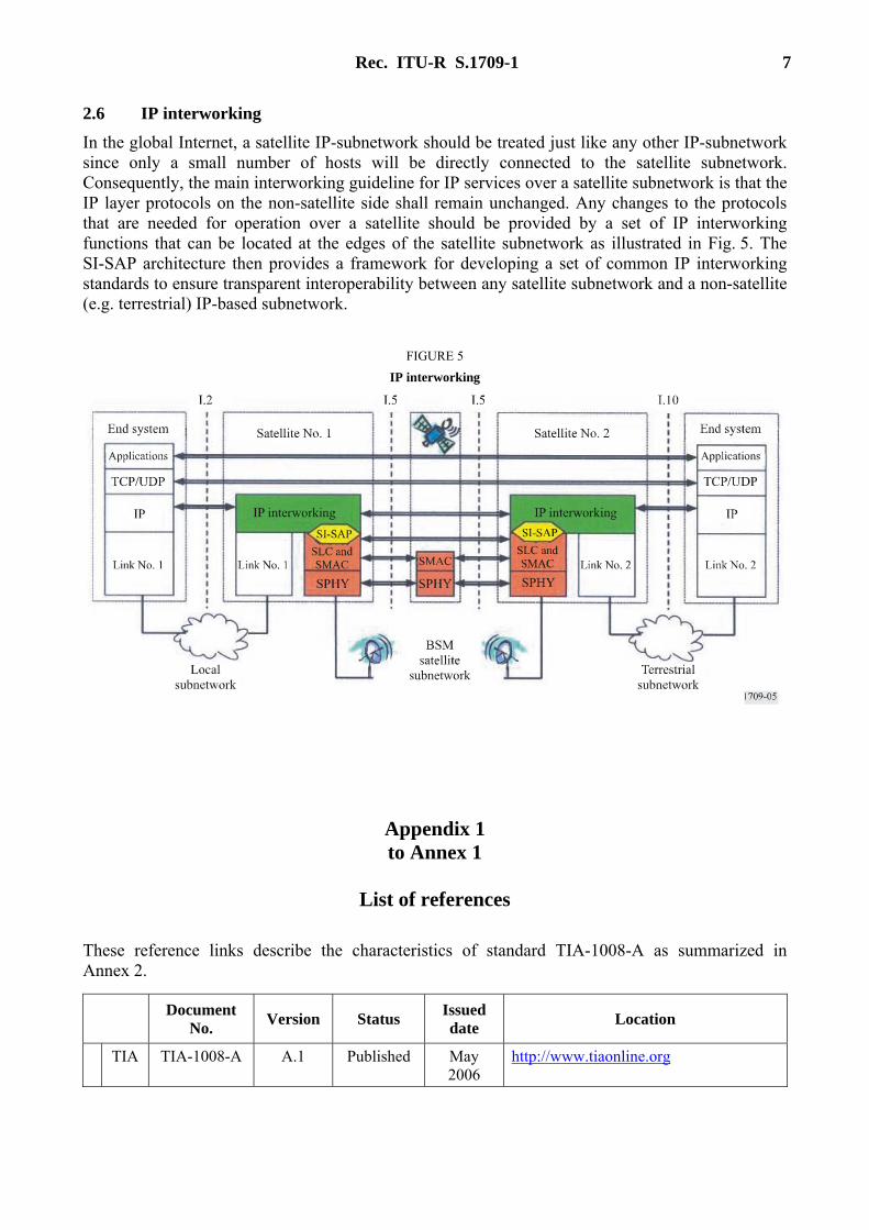
2.6 IP interworking In the global Internet, a satellite IP-subnetwork should be treated just like any other IP-subnetwork since only a small number of hosts will be directly connected to the satellite subnetwork. Consequently, the main interworking guideline for IP services over a satellite subnetwork is that the IP layer protocols on the non-satellite side shall remain unchanged. Any changes to the protocols that are needed for operation over a satellite should be provided by a set of IP interworking functions that can be located at the edges of the satellite subnetwork as illustrated in Fig. 5. The SI-SAP architecture then provides a framework for developing a set of common IP interworking standards to ensure transparent interoperability between any satellite subnetwork and a non-satellite (e.g. terrestrial) IP-based subnetwork.
FIGURE 5 IP interworking
Appendix 1 to Annex 1
List of references
These reference links describe the characteristics of standard TIA-1008-A as summarized in Annex 2.
Document No. Version Status Issued
date Location
TIA TIA-1008-A A.1 Published May 2006
http://www.tiaonline.org
8 Rec. ITU-R S.1709-1
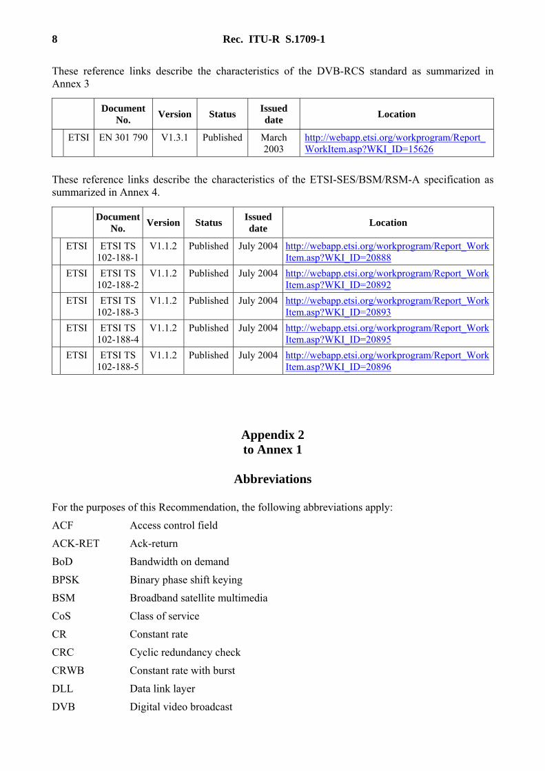
These reference links describe the characteristics of the DVB-RCS standard as summarized in Annex 3
Document No. Version Status Issued
date Location
ETSI EN 301 790 V1.3.1 Published March 2003
http://webapp.etsi.org/workprogram/Report_WorkItem.asp?WKI_ID=15626
These reference links describe the characteristics of the ETSI-SES/BSM/RSM-A specification as summarized in Annex 4.
Document No. Version Status Issued
date Location
ETSI ETSI TS 102-188-1
V1.1.2 Published July 2004 http://webapp.etsi.org/workprogram/Report_WorkItem.asp?WKI_ID=20888
ETSI ETSI TS 102-188-2
V1.1.2 Published July 2004 http://webapp.etsi.org/workprogram/Report_WorkItem.asp?WKI_ID=20892
ETSI ETSI TS 102-188-3
V1.1.2 Published July 2004 http://webapp.etsi.org/workprogram/Report_WorkItem.asp?WKI_ID=20893
ETSI ETSI TS 102-188-4
V1.1.2 Published July 2004 http://webapp.etsi.org/workprogram/Report_WorkItem.asp?WKI_ID=20895
ETSI ETSI TS 102-188-5
V1.1.2 Published July 2004 http://webapp.etsi.org/workprogram/Report_WorkItem.asp?WKI_ID=20896
Appendix 2 to Annex 1
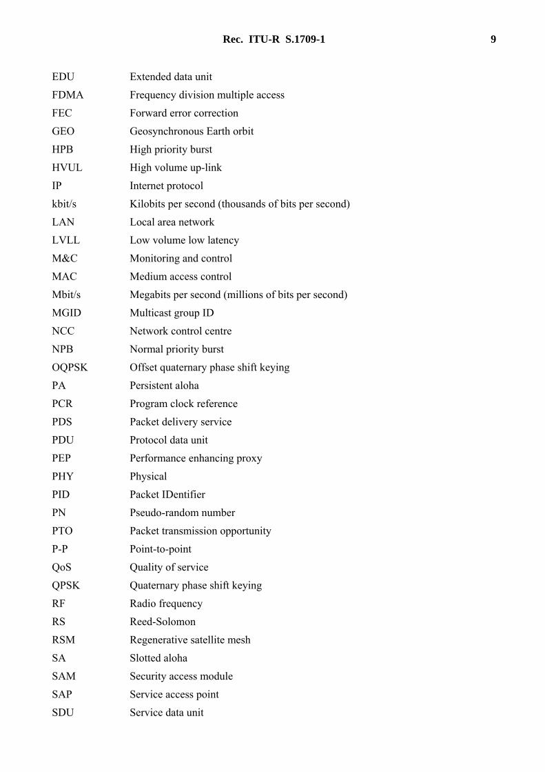
Abbreviations
For the purposes of this Recommendation, the following abbreviations apply:
ACF Access control field
ACK-RET Ack-return
BoD Bandwidth on demand
BPSK Binary phase shift keying
BSM Broadband satellite multimedia
CoS Class of service
CR Constant rate
CRC Cyclic redundancy check
CRWB Constant rate with burst
DLL Data link layer
DVB Digital video broadcast
Rec. ITU-R S.1709-1 9
EDU Extended data unit
FDMA Frequency division multiple access
FEC Forward error correction
GEO Geosynchronous Earth orbit
HPB High priority burst
HVUL High volume up-link
IP Internet protocol
kbit/s Kilobits per second (thousands of bits per second)
LAN Local area network
LVLL Low volume low latency
M&C Monitoring and control
MAC Medium access control
Mbit/s Megabits per second (millions of bits per second)
MGID Multicast group ID
NCC Network control centre
NPB Normal priority burst
OQPSK Offset quaternary phase shift keying
PA Persistent aloha
PCR Program clock reference
PDS Packet delivery service
PDU Protocol data unit
PEP Performance enhancing proxy
PHY Physical
PID Packet IDentifier
PN Pseudo-random number
PTO Packet transmission opportunity
P-P Point-to-point
QoS Quality of service
QPSK Quaternary phase shift keying
RF Radio frequency
RS Reed-Solomon
RSM Regenerative satellite mesh
SA Slotted aloha
SAM Security access module
SAP Service access point
SDU Service data unit
10 Rec. ITU-R S.1709-1
SES Satellite earth station
SI-SAP Satellite independent-SAP
SLC Satellite link control
SMAC Satellite MAC
ST Satellite terminal
TBTP Terminal burst time plan
TCP Transmission control protocol
TCT Time-slot composition table
TDM Time division multiplexing
TDMA Time division multiple access
TIM Terminal information message
UDC Up-link data channel
UDP User data protocol
UDTS User data transport services
ULPC Uplink power control
UW Unique word
VoIP Voice-over-IP
Annex 2
Air Interface Standard TIA-1008-A (IPoS)
CONTENTS
Page
1 Introduction .................................................................................................................... 11
2 Network architecture ...................................................................................................... 11
2.1 Network segments .............................................................................................. 11
2.2 Network interfaces.............................................................................................. 12
2.3 Remote terminal characteristics.......................................................................... 13
3 IPoS satellite interface .................................................................................................... 13
3.1 IPoS protocol reference model ........................................................................... 13
3.2 Layer-wise functional partitioning ..................................................................... 15
3.3 PHY layer ........................................................................................................... 15
3.4 Outroute satellite transmission ........................................................................... 15
Rec. ITU-R S.1709-1 11
Page
3.5 Inroute satellite transmission .............................................................................. 15
3.6 Data link layer (DLL) ......................................................................................... 16
3.7 Satellite link control (SLC) sublayer .................................................................. 16
3.8 Media access control (MAC) sublayer ............................................................... 16
3.9 Outroute multiplexing sublayer .......................................................................... 17
3.10 Network adaptation layer.................................................................................... 17
1 Introduction The solution provided in this section is an introduction to the Internet Protocol over Satellite (IPoS) standard that has been developed by the U.S. based Telecommunications Industry Association (TIA). IPoS outroute carriers (i.e. the broadcast carriers from a hub or broadcast terminal to many remotes) use a statistical multiplexing scheme compliant with the DVB data format and the distribution of IP traffic to the remote terminals which is based on the DVB multiprotocol encapsulation. The multiplexing sublayer on the outroute carrier permits the hub to transmit several traffic types, programmes, or services within the same outroute carrier and controls the transmission of each individual programme. The IPoS multiplexing sublayer is based on the Digital Video Broadcast/Motion Pictures Expert Group (DVB/MPEG) statistical multiplexing format.
This Annex gives a technical overview of the IPoS specification. Section 2 describes the network architecture for the IPoS system and Section 3 describes the protocol architecture adopted for the satellite air interface between remote terminals and the hub.
2 Network architecture
2.1 Network segments
IPoS is designed for use in a star satellite network that encompasses three major segments: 1. Hub segment: The hub segment supports Internet access of a large number of remote
terminals via satellite. It is composed of large hub earth stations and related equipment through which all traffic flows.
2. Space segment: The space segment consists of bent-pipe transponders on geosynchronous satellites that allow transmission in both directions between the hub and remote terminals. IPoS parameters and procedures are somewhat independent of the underlying spectrum whether 6/4 GHz, 14/10-11 GHz, 30/20 GHz frequency bands, or even the 8/7 GHz frequency band used by the satellite transponders; however, there are physical requirements involving radio-frequency parameters that are specific for each particular frequency band. The present version of the IPoS physical (PHY) layer interface assumes IPoS services using 14/10-11 GHz satellites with spectrum that is designated for fixed-satellite service (FSS).
3. User segment: In general, the IPoS user segment consists of thousands of user terminals, each of them capable of providing broadband, IP communications to a remote site. User terminals are also referred to in this standard as remote terminals. The remote terminals support the user hosts, or personal computers (PCs), running the applications. This support of user PCs could be broadly categorized as: – Single access point: where the host and the remote terminal are connected, e.g. through
a universal serial bus (USB) interface.
12 Rec. ITU-R S.1709-1
– Customer premises LAN: where the remote terminals provide access to a multiplicity of PCs. Customer LANs are considered external to the IPoS system.
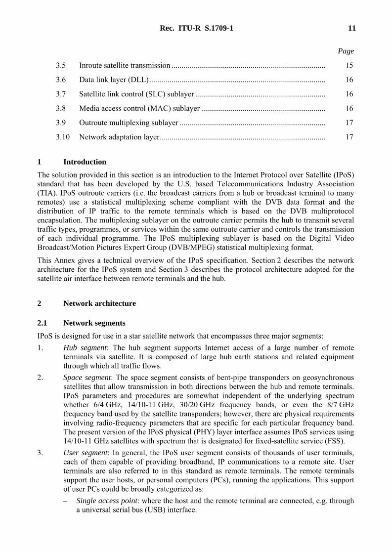
Figure 6 illustrates the highest-level components in the IPoS architecture and identifies the major internal and external interfaces in the IPoS system.
FIGURE 6 IPoS system architecture
2.2 Network interfaces The main interfaces in the IPoS system are: – Terminal LAN interface: This is the interface between the user hosts’ computers, or PCs,
and the remote terminals. The terminal LAN interface uses an Ethernet protocol that is not part of this standard.
– IPoS satellite interface: This is the interface where remote terminals and the hub exchange user, control, and management information. The IPoS satellite interface, or air interface, is the main focus of this standard.
– Hub terrestrial interface: This is the interface between the hub and the backbone connecting the hub to the external packet data networks, public Internet, or private data networks. The hub terrestrial interface uses IP protocols that are not part of this standard.
The IPoS satellite interface distinguishes between the two transmissions’ directions: – The outroute direction from the IPoS hub to the user terminals is broadcast over the entire
bandwidth allocated to the outroute carrier. Because the IPoS outroute can multiplex a multiplicity of transmissions, it streams to many remote terminals.

Rec. ITU-R S.1709-1 13
– The inroute direction from the remote terminals to the IPoS hub is P-P, either using a bandwidth assigned by the hub for individual remote terminals or using a bandwidth shared by all terminals on a contention basis.
2.3 Remote terminal characteristics The remote terminal is the access platform from which the user hosts access the services of the IPoS system. Whether or not a terminal requires the support of a PC is one of the critical methods used to categorize IPoS terminals. According to these criteria, there are two remote terminal categories: – PC-hosted: This type of terminal is primarily oriented toward consumer applications.
PC-hosted remote terminals operate as a PC peripheral, typically a USB peripheral, and significant support from the PC is required for operation. This support includes: – Downloading the peripheral’s software. – Enabling performance enhancement function. – Commissioning and management functions.
– Self-hosted: Self-hosted terminals are aimed at all classes of customers, i.e. consumer, small office, home office (SOHO) and enterprize market segments. The self-hosted remote terminals do not require an external PC to support their operation in the IPoS system. Self-hosted terminals can be fully managed by the hub, e.g. self-hosted remote terminals can have their software downloaded, and their configuration parameters set by the hub.
Another criterion for categorizing remote terminals is the type of return channel that a terminal uses to send data to the hub. Accordingly, remote terminals can be classified into: – Satellite-return channel: transmits back to the hub directly via the inroute satellite channels
part of the IPoS system. – Receive-only with terrestrial return: operates receive-only with respect to the satellite,
using some form of terrestrial return capability (e.g. a dial-up connection).
Table 2 summarizes typical characteristics of the various types of remote terminals currently defined in the IPoS system.
TABLE 2
IPoS terminals typical characteristics
Terminal name/features Hosting Return channel
Low-cost, two-way, broadband satellite PC peripheral PC Satellite
Low-cost, two-way, broadband self-hosted terminal Self Satellite
Receive-only lowest-cost satellite broadband, PC peripheral PC Dial-up
3 IPoS satellite interface
3.1 IPoS protocol reference model The IPoS protocol is a multilayered peer-to-peer protocol providing the mechanisms to exchange IP traffic and signalling information between the entities in the hub and remote terminals.
14 Rec. ITU-R S.1709-1
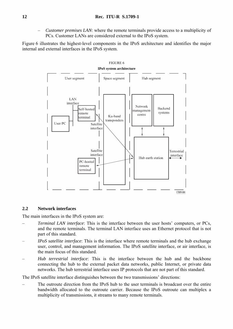
The IPoS protocol is structured according to the broadband satellite multimedia (BSM) protocol architecture as defined in TR 101 984. This architecture provides a split between satellite-dependent functions and satellite-independent functions, as illustrated in Fig. 7.
FIGURE 7 Protocol reference model
The protocol architecture separates satellite-dependent functions and satellite-independent functions via an interface designated for the SI-SAP. The purpose of this split is as follows: – Separate the satellite-specific aspects from the satellite-independent higher layer. This
separation is designed to permit future market developments, in particular IP enhancements. – Provide flexibility for the addition of more complex market segment-based solutions
(e.g. performance enhancing proxy (PEP)). – Elements above the SI-SAP can be ported with greater ease to new satellite systems. – Extensibility to support new higher-layer functionalities without major reengineering of
existing designs.
As shown in Fig. 7, the SI-SAP is positioned between the data link (layer 2) and network layers in the International Organization for Standardization (ISO) layering model. Elements above the SI-SAP can be, and indeed should be, designed without specific knowledge of the supporting satellite link layer. The satellite-independent layers in Fig. 7 are generic, including services not currently specified by IPoS such as IntServ, DiffServ, and IPv6.
The IPoS interface is organized into planes, layers, and directions of transmission over the satellite. There are three protocol planes: Plane 1: User-plane (U-Plane): provides the protocols needed for reliable transport of IP traffic
containing user information across the satellite interface. Plane 2: Control-plane (C-Plane): contains the signalling protocols needed to support and
control the satellite access connections and resources needed in the transport of user traffic.

Rec. ITU-R S.1709-1 15
Plane 3: Management-plane (M-Plane): concerned with the administration and messaging related to the commissioning of remote terminals, the billing of the users, performance, and alarm reporting. The management-plane is outside the scope of this standard.
Each of the IPoS planes is logically divided into three protocol sublayers. The protocol sublayers are used to decompose the overall system functionality into groupings of functions at the same abstraction level. – PHY layer: provides the lower-level functionality related to modulation, error control of the
information, and signalling streams transported across the interface. – Data link-control (DLC) layer: provides the multiplexing of the various streams as well as
reliable and efficient transport services. – Network-adaptation layer: controls user access to the satellite and controls radio resources
needed for this access.
3.2 Layer-wise functional partitioning This subsection gives the functional responsibilities for the layers in the satellite-dependent part of the IPoS interface.
3.3 PHY layer The physical-layer function provides the transmission and reception of the modulated waveforms used to transport the data provided by the data link and higher layers over the satellite. At the PHY, there is no distinction between the transport methods provided for U-Plane and C-Plane or M-Plane information. This distinction is made at higher layers.
The services provided by the PHY layer are grouped into the following categories: – The initial acquisition, synchronization, and ranging procedures with the hub, including the
timing alignment of the transmissions with the frame structure of the inroute carriers and the adjustment of the power transmitted by the remote terminals.
– The modulation, coding, error correction, scrambling, timing, and frequency synchronization of information flows, provided by the DLC’s U-Plane and C-Plane to the outroute and inroute carriers.
– The performance of local measurements such as received Eb/N0, recovered clock, and status and supervision of the physical parameters (such as timing) and their reporting to higher layers.
3.4 Outroute satellite transmission IPoS outroute carriers use a statistical multiplexing scheme compliant with the DVB data format and the distribution of IP traffic to the remote terminals is based on the DVB multiprotocol encapsulation. Symbol rates from 1 MSymbol/s to 45 MSymbol/s are supported, at FEC rates 1/2, 2/3, 3/4, 5/6 and 7/8 with DVB-S modulation and coding, and at FEC rates ranging from 1/4 to 9/10 with DVB-S2 modulation and coding.
3.5 Inroute satellite transmission An IPoS inroute uses offset quadrature phase shift keying (OQPSK) modulation at transmission rates of 64, 128, or 256 kSymbol/s when using rate 1/2 convolutional coding, or at transmission rates of 256, 512, 1 024 and 2 048 kSymbol/s when using Turbo and BCH coding.
16 Rec. ITU-R S.1709-1
IPoS uses demand-assigned multi-frequency time division multiple access (MF-TDMA) on its inroutes to allow terminals to transmit to the hub. The IPoS inroute has a 45 ms TDMA frame length divided into a variable number of slots. Transmissions from a terminal to the hub are referred to as a “burst.” A burst requires an integral number of slots for overhead and then carries an integral number of slots of data. These overhead slots are used to provide the burst preamble and to allow adequate time between bursts to ensure that consecutive bursts do not overlap in time.
3.6 Data link layer (DLL) The DLL provides the actual transport service over the IPoS network. It is divided into the following sublayers: – satellite link control (SLC); – media access control (MAC); – outroute multiplexing sublayer.
3.7 Satellite link control (SLC) sublayer The SLC layer is the sublayer of the DLC that is responsible for transmission of packets between remote terminals and the hub.
IPoS supports different delivery methods over the outroute and inroute directions.
A reliable error-free delivery method is used in the inroute direction using selective retransmissions. In this reliable delivery method, the receiving SLC entities deliver only error-free data packets to the higher layers.
Over the outroute where the transmission errors are very low (typical BER = 10−10), the transmit SLC delivers each data packet only once without retransmission of erroneous or missing packets.
The functional responsibilities of the SLC are: – Generation of session IDs and mapping incoming packets into the corresponding session. – Encryption of specific IP PDUs for user-to-user data privacy. – Segmentation and reassembly, which performs segmentation/reassembly of variable-length
higher layer data packets into smaller PDUs. – Delivery of data in sequence to the peer using the reliable/unreliable mode of delivery.
3.8 Media access control (MAC) sublayer
The services or functions provided by the MAC layer can be grouped into the following categories: – Data transfer: This service provides transfer of MAC interactions between peer MAC
entities. This service does not provide any data segmentation; therefore, the upper layers provide the segmentation/reassembly function.
– Reallocation of radio resources and MAC parameters: This service performs control procedures for identifiers that are allocated to a particular DLC layer by the network layer for an interval of time or on a permanent basis. It also performs procedures for the establishment and termination of transfer modes over the DLC layer.
– Error detection: Procedures for the detection of procedural errors or errors occurring during the transmission of frames.
Rec. ITU-R S.1709-1 17
3.9 Outroute multiplexing sublayer In the outroute direction, the multiplexing sublayer permits the hub to transmit several traffic types, programmes, or services within the same outroute carrier and controls the transmission of each individual programme. The IPoS-multiplexing sublayer is based on the digital video broadcast/motion pictures expert group (DVB/MPEG) statistical multiplexing format.
In this DVB/MPEG format, all the frames or packets associated with one of the traffic types have the same programme identifier PID. At the remote terminals, a demultiplexer breaks the outroute multiplex into specific transport streams with the remote terminal filtering only those that match the PID addresses configured in the terminal.
IPoS remote terminals are configured to filter two types of PID associated with the following types of transport streams, which are relevant to the IPoS system: Type 1: PSI tables, which provide both IPoS and non-IPoS terminals with configuration of services.
The IPoS terminals receive the PSI tables to determine the specific configuration of the IPoS system.
Type 2: IPoS user and control information, which is transported in the IPoS logical channels. The information contained in the IPoS logical channels can be targeted to all, a group, or individual IPoS terminals.
Outroute DVB/MPEG packets are broadcast over the entire outroute carrier bandwidth with IPoS terminals filtering those packets that do not match their own addresses. The addressing scheme is included as part of the transport packet header and MAC header.
3.10 Network adaptation layer The network adaptation layer function provides the following major subfunctions: – IP packet transport: This function performs the functions necessary to determine the class
of service of the IP packet based on packet type, application type, destination, and internal configuration.
– Traffic management: This function performs the traffic shedding and policing functions on IP packets before they are offered to the IPoS transport services.
– PEP: This function improves the performance of certain applications for improving service over a satellite link. PEP are often used to reduce the degradations in throughput experienced by transmission control protocol (TCP) applications because of the delays and losses in satellite links.
– Multicast proxy: This proxy adapts IP-multicast protocols (e.g. PIM-SM) to the appropriate IPoS transport services to provide the multicast.
The network adaptation layer is not part of the IPoS air interface specification.

18 Rec. ITU-R S.1709-1
Annex 3
Air Interface Standard ETSI EN 301 790 V1.3.1
CONTENTS
Page
1 Introduction .................................................................................................................... 19
2 Reference model of the satellite interaction network ..................................................... 19
2.1 Protocol stack model........................................................................................... 19
2.2 System model...................................................................................................... 20
2.3 Reference model of the satellite interactive network ......................................... 21
3 Forward link ................................................................................................................... 22
4 Return link baseband physical layer specification and multiple access definition......... 22
4.1 RCST synchronization........................................................................................ 22
4.1.1 Timing control .................................................................................................... 22
4.1.2 Carrier synchronization ...................................................................................... 23
4.1.3 Burst synchronization ......................................................................................... 23
4.1.4 Symbol clock synchronization............................................................................ 23
4.2 Burst format ........................................................................................................ 23
4.2.1 Traffic (TRF) burst formats ................................................................................ 23
4.2.2 Synchronization and acquisition burst formats................................................... 25
4.3 Modulation.......................................................................................................... 25
4.4 MAC messages ................................................................................................... 25
5 Protocol stack ................................................................................................................. 26
6 Capacity request categories ............................................................................................ 28
6.1 Continuous-rate assignment (CRA).................................................................... 28
6.2 Rate-based dynamic capacity (RBDC) ............................................................... 28
6.3 Volume-based dynamic capacity (VBDC) ......................................................... 28
6.4 Absolute volume-based dynamic capacity (AVBDC)........................................ 28
6.5 Free-capacity assignment (FCA) ........................................................................ 28
7 Multiple access ............................................................................................................... 29
7.1 MF-TDMA ......................................................................................................... 29
8 Security, identity and encryption.................................................................................... 29
Rec. ITU-R S.1709-1 19
1 Introduction The section describes the specifications for the provision of the interaction channel for satellite distribution systems, DVB-RCS.
Specifically, this section: – specifies the channel coding/modulation; two coding schemes are described: turbo and
concatenated coding. return channel satellite terminal (RCST) should implement both schemes, though within a session, terminals are not requested to change the coding scheme;
– specifies two types of traffic bursts carrying either ATM cells or MPEG2-TS (MPEG-2-transport streams) packets;
– specifies the MAC protocol for the return channel of the satellite link; – keeps compatibility of the return channel with DVB-S on the forward link; – specifies the terminal synchronization, capacity request categories and the security, identity
and encryption for the system.
2 Reference model of the satellite interaction network
2.1 Protocol stack model For interactive services supporting broadcast to the end user with return channel, a simple communications model consists of the following layers: – PHY layer: where all the physical (electrical) transmission parameters are defined. – Transport layer: defines all the relevant data structures and communication protocols like
data containers, etc. – Application layer: is the interactive application software and runtime environment
(e.g. home shopping application, script interpreter, etc.).
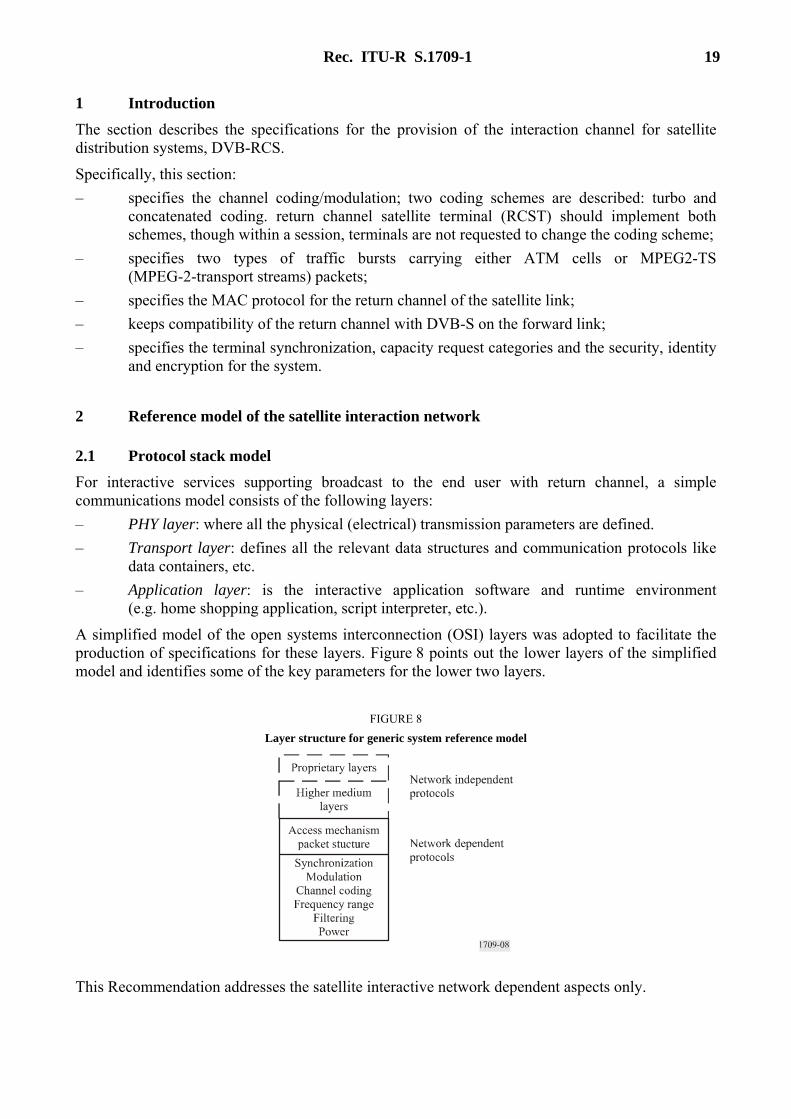
A simplified model of the open systems interconnection (OSI) layers was adopted to facilitate the production of specifications for these layers. Figure 8 points out the lower layers of the simplified model and identifies some of the key parameters for the lower two layers.
FIGURE 8 Layer structure for generic system reference model
This Recommendation addresses the satellite interactive network dependent aspects only.
20 Rec. ITU-R S.1709-1
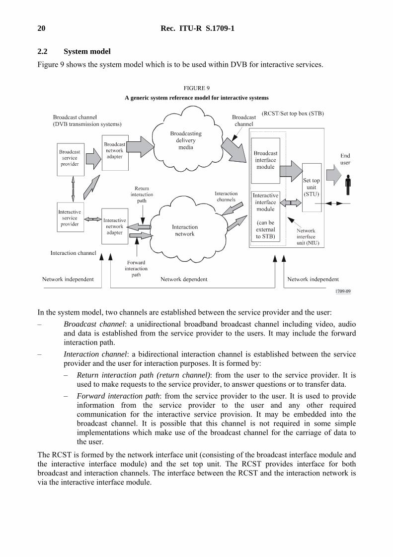
2.2 System model Figure 9 shows the system model which is to be used within DVB for interactive services.
FIGURE 9 A generic system reference model for interactive systems
In the system model, two channels are established between the service provider and the user: – Broadcast channel: a unidirectional broadband broadcast channel including video, audio
and data is established from the service provider to the users. It may include the forward interaction path.
– Interaction channel: a bidirectional interaction channel is established between the service provider and the user for interaction purposes. It is formed by: – Return interaction path (return channel): from the user to the service provider. It is
used to make requests to the service provider, to answer questions or to transfer data. – Forward interaction path: from the service provider to the user. It is used to provide
information from the service provider to the user and any other required communication for the interactive service provision. It may be embedded into the broadcast channel. It is possible that this channel is not required in some simple implementations which make use of the broadcast channel for the carriage of data to the user.
The RCST is formed by the network interface unit (consisting of the broadcast interface module and the interactive interface module) and the set top unit. The RCST provides interface for both broadcast and interaction channels. The interface between the RCST and the interaction network is via the interactive interface module.

Rec. ITU-R S.1709-1 21
2.3 Reference model of the satellite interactive network An overall satellite interactive network, within which a large number of RCSTs will operate, will comprise the following functional blocks, as shown in Fig. 10: – Network control centre (NCC): a NCC provides monitoring and control functions. It
generates control and timing signals for the operation of the satellite interactive network to be transmitted by one or several feeder stations.
– Traffic gateway (TG): a TG receives the RCST return signals, provides accounting functions, interactive services and/or connections to external public, proprietary and private service providers (databases, pay-per-view TV or video sources, software download, teleshopping, telebanking, financial services, stock market access, interactive games, etc.) and networks (Internet, ISDN, PSTN, etc.).
– Feeder: a feeder transmits the forward link signal, which is a standard satellite digital video broadcast (DVB-S) uplink, onto which are multiplexed the user data and/or the control and timing signals needed for the operation of the satellite interactive network.
FIGURE 10 Reference model for the satellite interactive network

22 Rec. ITU-R S.1709-1
The forward link carries signalling from the NCC and user traffic to RCST. The signalling from the NCC to RCST that is necessary to operate the return link system is called “forward-link signalling” in the following. Both the user traffic and forward-link signalling can be carried over different forward-link signals. Several RCST configurations are possible depending on the number of forward-link receivers present on the RCST.
3 Forward link The RCST should be able to receive digital signals conforming to EN 300 421, TR 101 202, ETS 300 802, EN 300 468, EN 301 192 and ETR 154.
4 Return link baseband physical layer specification and multiple access definition Specifications for the baseband physical layer are given in this Annex. Figure 11 represents the generic digital signal processing to be performed at the RCST transmitter side, from the burst formatting of the serial information bit-stream, to the modulation representing the digital to analogue conversion. The signal processing to be performed by each subset is described in the following sections.
FIGURE 11
Block diagram of the RCST return link baseband signal processing
4.1 RCST synchronization
4.1.1 Timing control The synchronization of the RCST is an important feature of the satellite interactive network. Constraints are imposed on the RCST to obtain an efficient TDMA system with minimum interference between users and maximum throughput, although they can be minimized if the NCC performs tasks such as satellite frequency translation error and common-mode Doppler compensation for RCST carrier frequency. For this reason, the synchronization scheme is based on information contained within the forward link signalling as follows: – network clock reference (NCR); – signalling in DVB/MPEG2-TS private sections.
The NCR is distributed with a specific packet IDentifier (PID) within the MPEG2 transport stream that carries the forward-link signalling. The NCR distribution follows the program clock reference (PCR) distribution mechanism as defined in ISO/IEC 13818-1, which is usually derived from an MPEG video encoder, whereas here the NCR is derived from the NCC reference clock. The NCC reference clock will have an accuracy of 5 ppm or better.
Rec. ITU-R S.1709-1 23
4.1.2 Carrier synchronization The MPEG-2 TS that carries the forward-link signalling contains NCR information which provides a 27 MHz reference of the NCC reference clock to the RCST. The RCST reconstructs the reference clock from the received NCR information as implemented in MPEG decoders for MPEG-2-transport streams (MPEG-2 TS). The RCST then performs a comparison to determine the offset between the local reference clock which controls the RCST up-converter local oscillator and the reference clock recovered from the received NCR. It then compensates the carrier frequency according to this offset. This local carrier synchronization provides a way of adjusting the transmit frequency of all RCST on the network to almost the same frequency.
Normalized carrier frequency accuracy should be better than 10−8 (root mean square).
4.1.3 Burst synchronization The RCST retrieve the centre frequency, the start time and the duration of their transmit bursts by examining the forward-link signalling.
The contention between RCST on the return link is resolved as described in this specification.
The bursts are sent according to the burst time plan (BTP) received in the forward-link signalling. The BTP is expressed in terms of centre frequency and absolute start time (given in NCR-counter value) of superframes and associated frequency and time offsets of burst allocations along with a description of the time-slot properties. A superframe always starts at a given value of the RCST local NCR counter, which serves as a reference for all burst allocations within the superframe. For the purpose of synchronizing to the network the RCST reconstructs, in addition to the reference clock, the absolute value of the NCC reference clock. The RCST compares the reconstructed value with the NCR value given by the BTP. The time reference for counting time-slots occurs when the values are equal.
Burst synchronization accuracy should be within 50% of a symbol period. The resolution should be 1 NCR count interval. The burst synchronization accuracy is the worst-case deviation of the scheduled start of burst time and the actual start of burst time at the transmitter output. The scheduled start of burst time is the point in time when the ideal reconstructed NCR equals the value written in the terminal BTP (TBTP) for that burst. The ideal reconstructed NCR is defined as observed at the output of an ideal delay-less DVB-S receiver. Compensation for the receiver delay, if required to achieve the specified accuracy, should be done by the RCST.
4.1.4 Symbol clock synchronization The symbol clock for the transmitter should be locked to the NCR based clock, in order to avoid time drift with respect to the NCC reference clock. The RCST need not compensate for symbol clock Doppler.
Symbol clock accuracy should be within 20 ppm from the nominal symbol rate value in the time-slot composition table (TCT). The symbol clock rate should have a short-term stability that limits the time error of any symbol within a burst to 1/20 symbol duration.
4.2 Burst format There are four types of bursts: traffic (TRF), acquisition (ACQ), synchronization (SYNC) and common signalling channel (CSC). The burst formats are described in the following.
4.2.1 Traffic (TRF) burst formats Traffic (TRF) bursts are used for carrying useful data from the RCST to the gateway. Two types of traffic bursts carrying either ATM cells or MPEG-2 TS packets are defined here below. A TRF is usually followed by a guard time to decrease transmitted power and compensate for time offset.
24 Rec. ITU-R S.1709-1
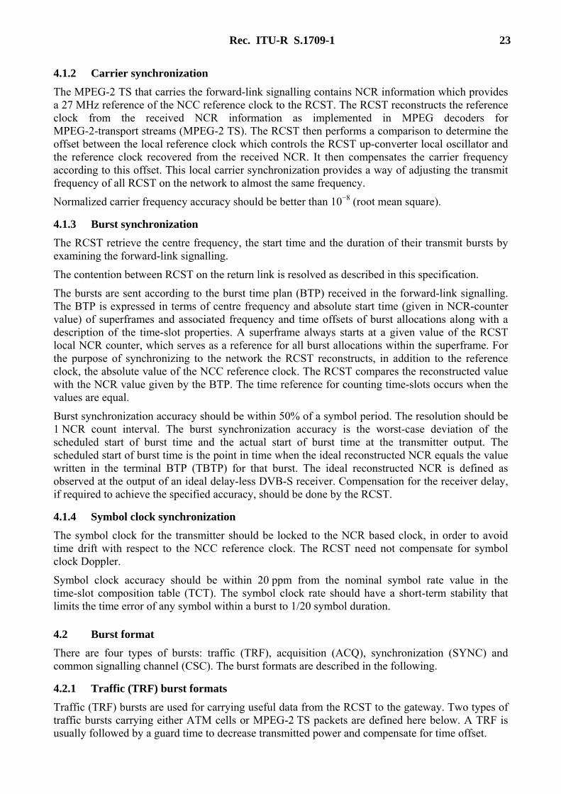
4.2.1.1 ATM TRF burst The payload of an ATM traffic burst is composed of Natm concatenated ATM cells, each of length 53 bytes, plus an optional Np,atm byte prefix. ATM cells follow the structure of an ATM cell but do not necessarily support ATM classes of service. See Fig. 12 for a description of the ATM TRF burst.
FIGURE 12 Composition of an ATM TRF burst
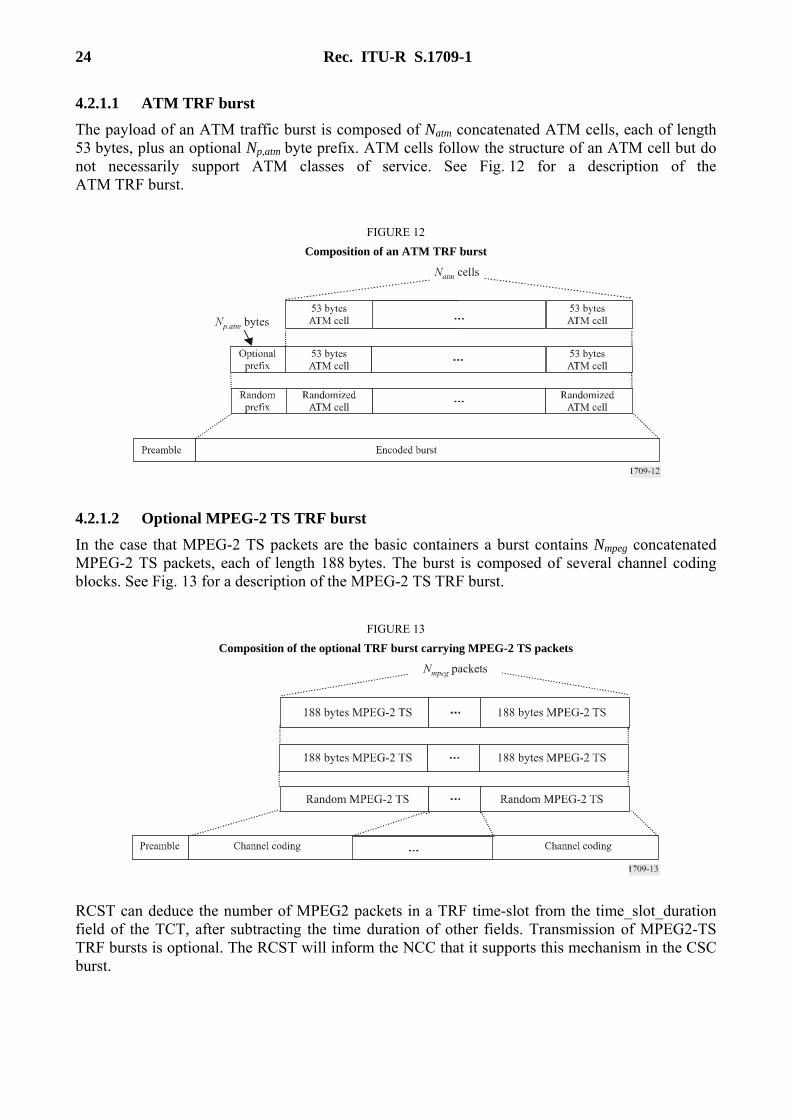
4.2.1.2 Optional MPEG-2 TS TRF burst In the case that MPEG-2 TS packets are the basic containers a burst contains Nmpeg concatenated MPEG-2 TS packets, each of length 188 bytes. The burst is composed of several channel coding blocks. See Fig. 13 for a description of the MPEG-2 TS TRF burst.
FIGURE 13 Composition of the optional TRF burst carrying MPEG-2 TS packets
RCST can deduce the number of MPEG2 packets in a TRF time-slot from the time_slot_duration field of the TCT, after subtracting the time duration of other fields. Transmission of MPEG2-TS TRF bursts is optional. The RCST will inform the NCC that it supports this mechanism in the CSC burst.

Rec. ITU-R S.1709-1 25
4.2.2 Synchronization and acquisition burst formats Synchronization and acquisition bursts are required to accurately position RCST burst transmissions during and after logon. Two separate burst types are defined for this purpose (SYNC and ACQ) as defined in the following paragraphs.
4.2.2.1 Synchronization (SYNC) burst format A SYNC burst is used by an RCST for the purpose of maintaining synchronization and sending control information to the system. SYNC bursts are composed of a preamble for burst detection, an optional Np,sync byte satellite access control (SAC) field, with the appropriate error control coding. Like a TRF a SYNC is usually followed by a guard time to decrease transmitted power and compensate for time offset. Figure 14 depicts the SYNC burst. The extent to which the SYNC burst is used depends on the capabilities of the NCC. NOTE 1 – SYNC bursts can be used in contention mode.
FIGURE 14 Composition of a SYNC burst
4.3 Modulation The signal should be modulated using QPSK, with baseband shaping.
4.4 MAC messages All methods described below can be used by RCST for capacity requests and monitoring and control (M&C) messages. One or more of the methods may be employed in a satellite interactive network. For the particular implementation, the RCST are configured at the time of logon by the logon initialize descriptor that is transmitted in a terminal information message (TIM).
The SYNC and the optional prefix attached to ATM TRF bursts contain the SAC field composed of signalling information added by the RCST for the purpose of requesting capacity on the session, or other additional MAC information. The SAC is composed of optional sub-fields that are defined in Fig. 15.

26 Rec. ITU-R S.1709-1
FIGURE 15 Composition of the SAC field
5 Protocol stack On the return link the protocol stack is based on ATM cells or optional MPEG-2 TS packets mapped onto TDMA bursts. For transmission of IP datagrams, the protocol stacks used on the return link are as follows: – ATM-based return link: IP/AAL5/ATM; – Optional MPEG return link: multiprotocol over MPEG-2 transport streams encapsulation. In the forward link the protocol stack is based on the DVB/MPEG-2 TS standard (see TR 101 154). For transmission of IP datagrams, the protocols stacks used on forward link are as follows: – multiprotocol encapsulation over MPEG-2 transport streams; – optionally IP/AAL5/ATM/MPEG-TS in data piping mode so as to enable direct terminal to
terminal communications in regenerative satellite systems.
Figures 16 and 17 show examples for protocol stack for traffic and signalling, respectively.

Rec. ITU-R S.1709-1 27
FIGURE 16 Example of protocol stack for user traffic with Type A RCST
(IP/AAL5/ATM/MPEG2/DVBS is optional in the forward link)
FIGURE 17 Protocol stack for signalling
28 Rec. ITU-R S.1709-1
6 Capacity request categories The time-slot allocation process should support five capacity categories: – continuous-rate assignment (CRA); – rate-based dynamic capacity (RBDC); – volume-based dynamic capacity (VBDC); – absolute volume-based dynamic capacity (AVBDC); – free-capacity assignment (FCA).
6.1 Continuous-rate assignment (CRA) CRA is rate capacity which should be provided in full for each and every superframe while required. Such capacity should be negotiated directly between the RCST and the NCC.
6.2 Rate-based dynamic capacity (RBDC) RBDC is rate capacity which is requested dynamically by the RCST. RBDC capacity should be provided in response to explicit requests from the RCST to the NCC, such requests being absolute (i.e. corresponding to the full rate currently being requested). Each request should override all previous RBDC requests from the same RCST, and should be subject to a maximum rate limit negotiated directly between the RCST and the NCC.
To prevent a terminal anomaly resulting in a hanging capacity assignment, the last RBDC request received by the NCC from a given terminal should automatically expire after a time-out period whose default value is two superframes, such expiry resulting in the RBDC being set to zero rate. The time-out can be configured between one and 15 superframes (if set to 0, the time-out mechanism is disabled) by the optional mechanism of § 8.
CRA and RBDC can be used in combination, with CRA providing a fixed minimum capacity per superframe and RBDC giving a dynamic variation component on top of the minimum.
6.3 Volume-based dynamic capacity (VBDC) VBDC is volume capacity which is requested dynamically by the RCST. VBDC capacity should be provided in response to explicit requests from the RCST to the NCC, such requests being cumulative (i.e. each request should add to all previous requests from the same RCST). The cumulative total per RCST should be reduced by the amount of this capacity category assigned in each superframe.
6.4 Absolute volume-based dynamic capacity (AVBDC) AVBDC is volume capacity which is requested dynamically by the RCST. This VBDC capacity should be provided in response to explicit requests from the RCST to the NCC, such requests being absolute (i.e. this request replaces the previous ones from the same RCST). The AVBDC is used instead of VBDC when the RCST senses that the VBDC request might be lost (for example in the case of contention minislots).
6.5 Free-capacity assignment (FCA) FCA is volume capacity which should be assigned to RCST from capacity which would be otherwise unused. Such capacity assignment should be automatic and should not involve any signalling from the RCST to the NCC. It should be possible for the NCC to inhibit FCA for any RCST or RCST.
Rec. ITU-R S.1709-1 29
FCA should not be mapped to any traffic category, since availability is highly variable. Capacity assigned in this category is intended as bonus capacity which can be used to reduce delays on any traffic which can tolerate delay jitter.
7 Multiple access The multiple-access capability is either fixed or dynamic slot multi-frequency time division multiple access (MF-TDMA). RCST should indicate their capability by using the MF-TDMA field present on the CSC burst.
7.1 MF-TDMA The satellite access scheme is MF-TDMA. MF-TDMA allows a group of RCST to communicate with a gateway using a set of carrier frequencies, each of which is divided into time-slots. The NCC will allocate to each active RCST a series of bursts, each defined by a frequency, a bandwidth, a start time and a duration.
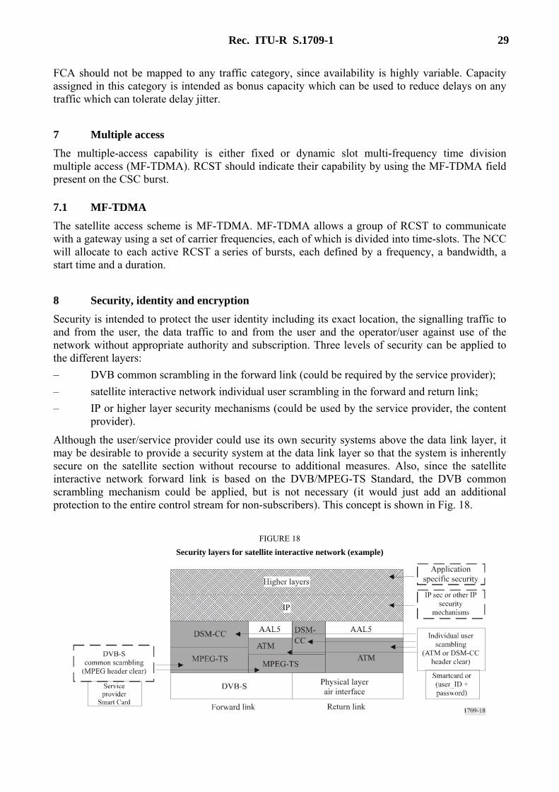
8 Security, identity and encryption Security is intended to protect the user identity including its exact location, the signalling traffic to and from the user, the data traffic to and from the user and the operator/user against use of the network without appropriate authority and subscription. Three levels of security can be applied to the different layers: – DVB common scrambling in the forward link (could be required by the service provider); – satellite interactive network individual user scrambling in the forward and return link; – IP or higher layer security mechanisms (could be used by the service provider, the content
provider).
Although the user/service provider could use its own security systems above the data link layer, it may be desirable to provide a security system at the data link layer so that the system is inherently secure on the satellite section without recourse to additional measures. Also, since the satellite interactive network forward link is based on the DVB/MPEG-TS Standard, the DVB common scrambling mechanism could be applied, but is not necessary (it would just add an additional protection to the entire control stream for non-subscribers). This concept is shown in Fig. 18.
FIGURE 18 Security layers for satellite interactive network (example)
30 Rec. ITU-R S.1709-1
Annex 4
Air interface specifications for global broadband communications between earth stations and regenerative satellites based on ETSI BSM/RSM-A
CONTENTS
Page
1 Scope .............................................................................................................................. 31
2 RSM-A air interface overview ....................................................................................... 31
2.1 RSM-A description............................................................................................. 31
2.2 RSM-A protocol architecture ............................................................................. 31
3 Physical layer.................................................................................................................. 32
3.1 Uplink ................................................................................................................. 34
3.1.1 Coding................................................................................................................. 35
3.1.2 Frame structure ................................................................................................... 35
3.1.3 Modulation.......................................................................................................... 36
3.1.4 Uplink carrier modes .......................................................................................... 36
3.1.5 Uplink power control .......................................................................................... 37
3.2 Downlink ............................................................................................................ 38
3.2.1 Coding................................................................................................................. 39
3.2.2 Frame structure ................................................................................................... 39
3.2.3 Modulation.......................................................................................................... 40
3.2.4 Downlink carrier modes ..................................................................................... 40
3.3 Other physical layer functions ............................................................................ 41
4 Data link layer ................................................................................................................ 41
4.1 SLC sublayer functions....................................................................................... 41
4.2 SMAC sublayer .................................................................................................. 41
4.3 Modes of operation ............................................................................................. 42
4.4 Class of service (CoS) and related concepts....................................................... 42
4.5 Bandwidth management-resource allocation and queue management ............... 44
4.5.1 Rate-oriented sessions ........................................................................................ 45
4.5.2 Volume-oriented sessions................................................................................... 45
4.5.3 Contention-mode access ..................................................................................... 45
4.5.4 Persistent aloha ................................................................................................... 45
5 Security access module – Functional description........................................................... 45

Rec. ITU-R S.1709-1 31
1 Scope This Annex gives a detailed introduction to the air interface, which has now been published by ETSI as the SES/BSM RSM-A specifications (see ETSI TS 102 188-1~7 and 102 189-1~3).
2 RSM-A air interface overview
2.1 RSM-A description The air interface has been published by ETSI as the SES/BSM RSM-A specifications (see ETSI TS 102 188-1~7 and 102 189-1~3). The following clauses give a summary of this air interface. This air interface standard specifies the physical and data link layers below the ETSI SES/BSM defined SI-SAP (see ETSI TS 102 292).
The RSM-A system uses a regenerative satellite that supports a fully meshed topology, where data can be transmitted between any pair of satellite terminals in a single hop.
All satellite terminals employ the same air-interface using FDMA-TDMA transmissions in the uplink to the satellite and TDM in the downlink from the satellite. Different sizes of the transmission platform support user-data burst rates from the low kbit/s to multiple Mbit/s.
The uplink uses spot beams that provide coverage for cells geographically distributed over the satellite coverage area. The downlink also uses spot beams for P-P services but in addition to these spot beams, there are separate downlink shaped beams that cover a reconfigurable portion of the satellite coverage area.
The satellite assigns an uplink bandwidth in each beam to individual terminals as required. All packets received at the satellite from all beams are recovered and switched to their destination downlink beams per the MAC-address-field in the packet-header. Packets destined for same destination beam are grouped and transmitted in the downlink direction via very high-rate TDM carrier bursts. Both end-user and gateway terminal types dynamically soft-share the total available bandwidth as needed to support the traffic flow in each direction.
2.2 RSM-A protocol architecture The ETSI/BSM network architecture (see ETSI TS 102 292) provides a split between satellite dependent functions and satellite independent functions. The purpose of this split is as follows: – to separate the satellite specific aspects (i.e. a Ka-band GEO satellite with a packet switch)
from the satellite independent higher layer. This separation is designed to permit future market developments, in particular IP-layer protocol developments;
– provide flexibility for the addition of different market segment-based solutions in the higher layers (e.g., performance enhancing proxies (PEPs) and application gateways).
This interface is termed the satellite independent-service access point (SI-SAP) (see ETSI TS 102 292). In the OSI layering model, the SI-SAP is positioned between the link and network layers.
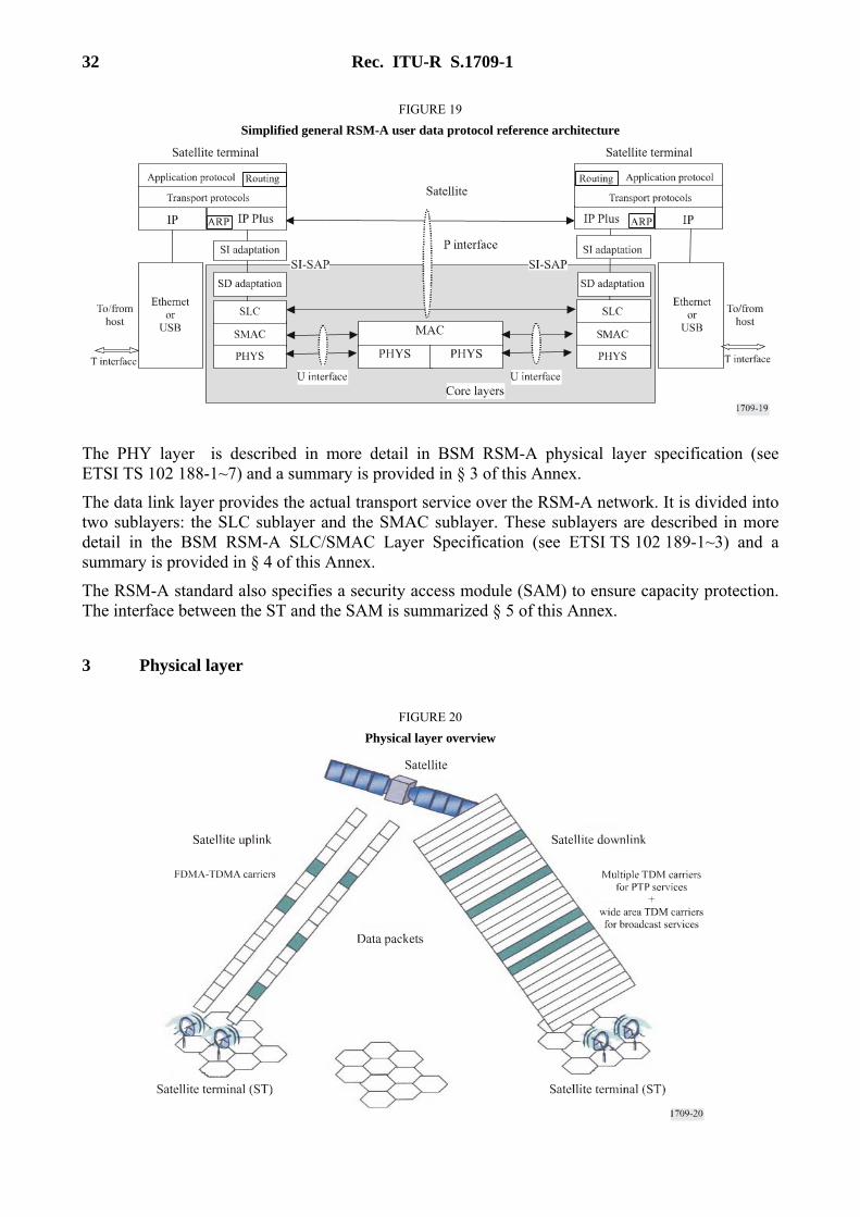
The protocol architecture for the baseline satellite terminal to satellite terminal (ST-to-ST) configuration is shown in Fig. 19. Within each ST, the SI-SAP provides the interface to the RSM-A core layers, consisting of the SLC, SMAC and PHY layers.
The regenerative satellite provides MAC layer functionality such as bandwidth-on-demand (BoD); MAC packet switching and MAC replication.
32 Rec. ITU-R S.1709-1
FIGURE 19 Simplified general RSM-A user data protocol reference architecture
The PHY layer is described in more detail in BSM RSM-A physical layer specification (see ETSI TS 102 188-1~7) and a summary is provided in § 3 of this Annex.
The data link layer provides the actual transport service over the RSM-A network. It is divided into two sublayers: the SLC sublayer and the SMAC sublayer. These sublayers are described in more detail in the BSM RSM-A SLC/SMAC Layer Specification (see ETSI TS 102 189-1~3) and a summary is provided in § 4 of this Annex.
The RSM-A standard also specifies a security access module (SAM) to ensure capacity protection. The interface between the ST and the SAM is summarized § 5 of this Annex.
3 Physical layer
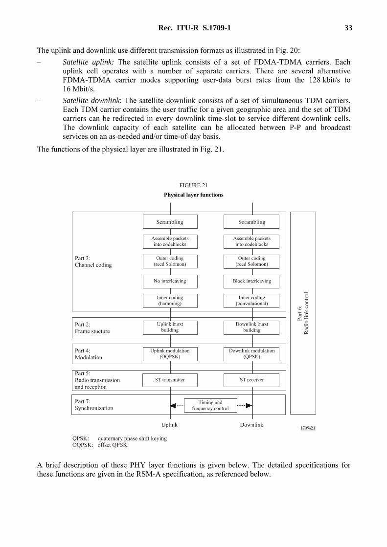
FIGURE 20 Physical layer overview
Rec. ITU-R S.1709-1 33
The uplink and downlink use different transmission formats as illustrated in Fig. 20: – Satellite uplink: The satellite uplink consists of a set of FDMA-TDMA carriers. Each
uplink cell operates with a number of separate carriers. There are several alternative FDMA-TDMA carrier modes supporting user-data burst rates from the 128 kbit/s to 16 Mbit/s.
– Satellite downlink: The satellite downlink consists of a set of simultaneous TDM carriers. Each TDM carrier contains the user traffic for a given geographic area and the set of TDM carriers can be redirected in every downlink time-slot to service different downlink cells. The downlink capacity of each satellite can be allocated between P-P and broadcast services on an as-needed and/or time-of-day basis.
The functions of the physical layer are illustrated in Fig. 21.
FIGURE 21 Physical layer functions
A brief description of these PHY layer functions is given below. The detailed specifications for these functions are given in the RSM-A specification, as referenced below.
34 Rec. ITU-R S.1709-1
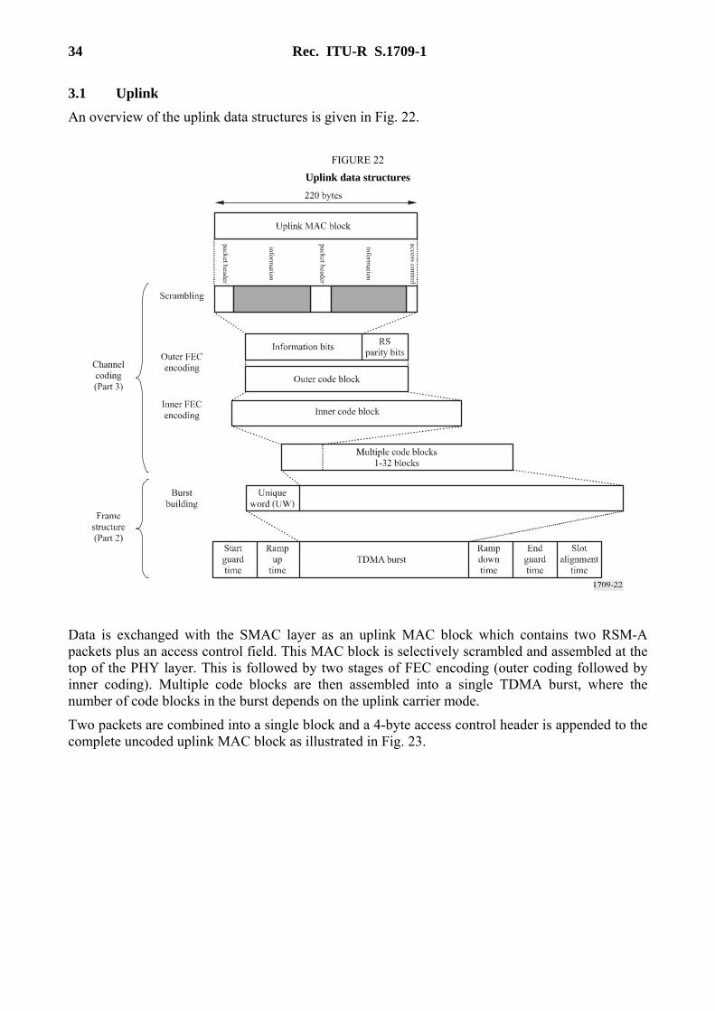
3.1 Uplink An overview of the uplink data structures is given in Fig. 22.
FIGURE 22 Uplink data structures
Data is exchanged with the SMAC layer as an uplink MAC block which contains two RSM-A packets plus an access control field. This MAC block is selectively scrambled and assembled at the top of the PHY layer. This is followed by two stages of FEC encoding (outer coding followed by inner coding). Multiple code blocks are then assembled into a single TDMA burst, where the number of code blocks in the burst depends on the uplink carrier mode.
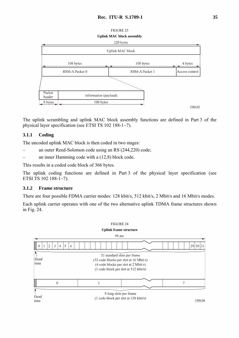
Two packets are combined into a single block and a 4-byte access control header is appended to the complete uncoded uplink MAC block as illustrated in Fig. 23.
Rec. ITU-R S.1709-1 35
FIGURE 23 Uplink MAC block assembly
The uplink scrambling and uplink MAC block assembly functions are defined in Part 3 of the physical layer specification (see ETSI TS 102 188-1~7).
3.1.1 Coding The uncoded uplink MAC block is then coded in two stages: – an outer Reed-Solomon code using an RS (244,220) code; – an inner Hamming code with a (12,8) block code.
This results in a coded code block of 366 bytes.
The uplink coding functions are defined in Part 3 of the physical layer specification (see ETSI TS 102 188-1~7).
3.1.2 Frame structure There are four possible FDMA carrier modes: 128 kbit/s, 512 kbit/s, 2 Mbit/s and 16 Mbit/s modes.
Each uplink carrier operates with one of the two alternative uplink TDMA frame structures shown in Fig. 24.
FIGURE 24 Uplink frame structure

36 Rec. ITU-R S.1709-1
Each carrier is partitioned into a dead time period followed by a fixed number of time-slots for code block transmission as shown. The number of time-slots is a function of the TDMA slot format as follows: – The uplink frame consists of 32 standard slots for the 16 Mbit/s, 2 Mbit/s and 512 kbit/s
carrier modes. – The uplink frame consists of 8 long slots for the 128 kbit/s carrier mode.
The uplink frame structures and burst structures are defined in Part 2 of the physical layer specification (see ETSI TS 102 189-1~3).
The FDMA-TDMA carrier modes can be flexibly configured for each cell to provide user data rates from 128 kbit/s to over 16 Mbit/s. Within each FDMA carrier, the TDMA time-slots are dynamically allocated: each slot can be allocated for either multiple access (i.e. contention) or for reservation access (i.e. to one specific ST).
A single TDMA burst is positioned within each time-slot. Each burst is preceded and followed by a guard time and power ramping time as illustrated in Fig. 25. The guard time is used to prevent interference between adjacent time-slots and the power ramping times are used to key-on and key-off the uplink carrier.
FIGURE 25 Uplink slot and burst structure
(not to scale)
The TDMA burst comprises a UW which is used for synchronization, followed by a traffic field composed of between 1 and 32 code blocks. The number of code blocks depends on the carrier mode.
The uplink burst structures are defined in Part 2 of the physical layer specification (see ETSI TS 102 188-1~7).
3.1.3 Modulation The uplink uses OQPSK modulation. The modulation rate is determined by the carrier mode. The uplink modulation functions are defined in Part 4 of the physical layer specification (see ETSI TS 102 188-1~7).
3.1.4 Uplink carrier modes
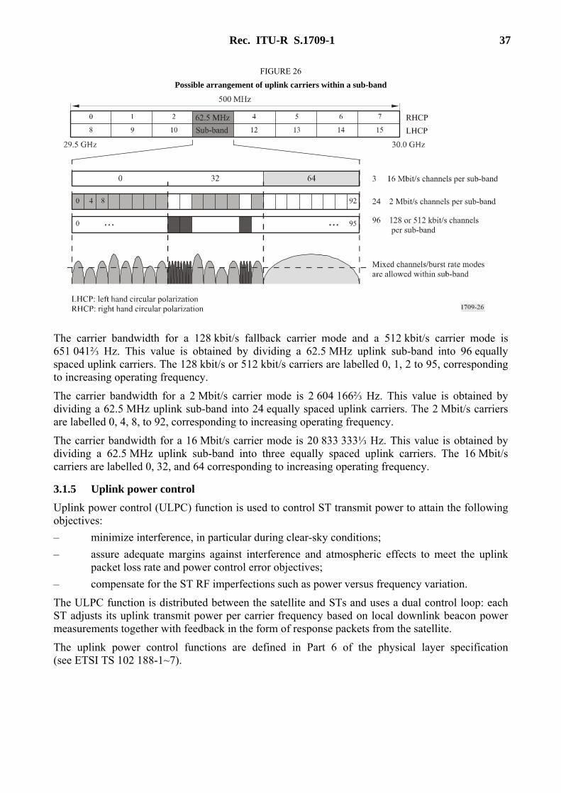
The uplink frequency band of 500 MHz is divided into 16 sub-bands of 62.5 MHz; 8 sub-bands for each of two polarizations.
Each uplink sub-band can be independently configured for a combination of 128 kbit/s, 512 kbit/s, 2 Mbit/s or 16 Mbit/s carrier modes. An illustration of the possible configuration of one sub-band is illustrated in Fig. 26.
Rec. ITU-R S.1709-1 37
FIGURE 26 Possible arrangement of uplink carriers within a sub-band
The carrier bandwidth for a 128 kbit/s fallback carrier mode and a 512 kbit/s carrier mode is 651 041⅔ Hz. This value is obtained by dividing a 62.5 MHz uplink sub-band into 96 equally spaced uplink carriers. The 128 kbit/s or 512 kbit/s carriers are labelled 0, 1, 2 to 95, corresponding to increasing operating frequency.
The carrier bandwidth for a 2 Mbit/s carrier mode is 2 604 166⅔ Hz. This value is obtained by dividing a 62.5 MHz uplink sub-band into 24 equally spaced uplink carriers. The 2 Mbit/s carriers are labelled 0, 4, 8, to 92, corresponding to increasing operating frequency.
The carrier bandwidth for a 16 Mbit/s carrier mode is 20 833 333⅓ Hz. This value is obtained by dividing a 62.5 MHz uplink sub-band into three equally spaced uplink carriers. The 16 Mbit/s carriers are labelled 0, 32, and 64 corresponding to increasing operating frequency.
3.1.5 Uplink power control Uplink power control (ULPC) function is used to control ST transmit power to attain the following objectives: – minimize interference, in particular during clear-sky conditions; – assure adequate margins against interference and atmospheric effects to meet the uplink
packet loss rate and power control error objectives; – compensate for the ST RF imperfections such as power versus frequency variation.
The ULPC function is distributed between the satellite and STs and uses a dual control loop: each ST adjusts its uplink transmit power per carrier frequency based on local downlink beacon power measurements together with feedback in the form of response packets from the satellite.
The uplink power control functions are defined in Part 6 of the physical layer specification (see ETSI TS 102 188-1~7).
38 Rec. ITU-R S.1709-1
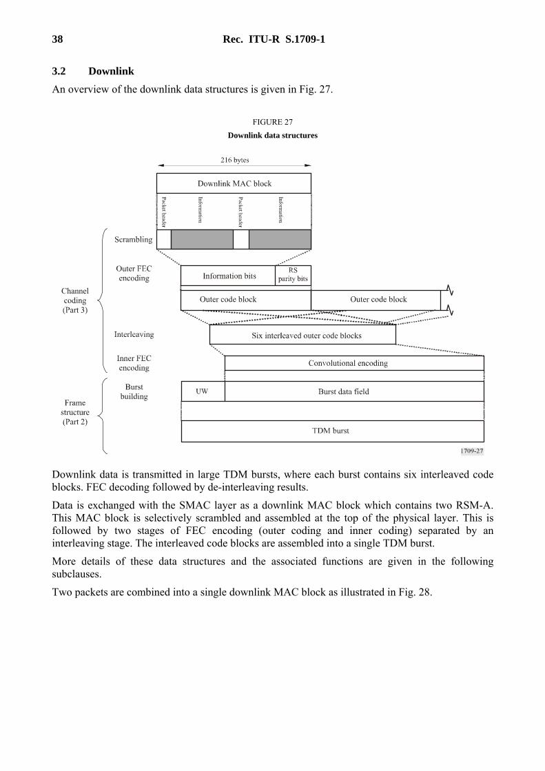
3.2 Downlink An overview of the downlink data structures is given in Fig. 27.
FIGURE 27 Downlink data structures
Downlink data is transmitted in large TDM bursts, where each burst contains six interleaved code blocks. FEC decoding followed by de-interleaving results.
Data is exchanged with the SMAC layer as a downlink MAC block which contains two RSM-A. This MAC block is selectively scrambled and assembled at the top of the physical layer. This is followed by two stages of FEC encoding (outer coding and inner coding) separated by an interleaving stage. The interleaved code blocks are assembled into a single TDM burst.
More details of these data structures and the associated functions are given in the following subclauses.
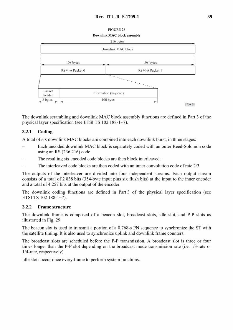
Two packets are combined into a single downlink MAC block as illustrated in Fig. 28.
Rec. ITU-R S.1709-1 39
FIGURE 28 Downlink MAC block assembly
The downlink scrambling and downlink MAC block assembly functions are defined in Part 3 of the physical layer specification (see ETSI TS 102 188-1~7).
3.2.1 Coding A total of six downlink MAC blocks are combined into each downlink burst, in three stages: – Each uncoded downlink MAC block is separately coded with an outer Reed-Solomon code
using an RS (236,216) code. – The resulting six encoded code blocks are then block interleaved. – The interleaved code blocks are then coded with an inner convolution code of rate 2/3.
The outputs of the interleaver are divided into four independent streams. Each output stream consists of a total of 2 838 bits (354-byte input plus six flush bits) at the input to the inner encoder and a total of 4 257 bits at the output of the encoder.
The downlink coding functions are defined in Part 3 of the physical layer specification (see ETSI TS 102 188-1~7).
3.2.2 Frame structure The downlink frame is composed of a beacon slot, broadcast slots, idle slot, and P-P slots as illustrated in Fig. 29.
The beacon slot is used to transmit a portion of a 0.768-s PN sequence to synchronize the ST with the satellite timing. It is also used to synchronize uplink and downlink frame counters.
The broadcast slots are scheduled before the P-P transmission. A broadcast slot is three or four times longer than the P-P slot depending on the broadcast mode transmission rate (i.e. 1/3-rate or 1/4-rate, respectively).
Idle slots occur once every frame to perform system functions.

40 Rec. ITU-R S.1709-1
FIGURE 29 Downlink frame structure
The transmission rate is at the full rate during P-P time-slots. The transmission rate during the beacon slot and idle slot is at the 1/3-rate and the transmission rate during the broadcast slots is at either 1/3-rate or 1/4-rate. The frame structure permits a variable number of broadcast slots (allocated in increments of three or four P-P slots, depending on the rate) with the remaining slots being allocated to P-P. The following range of configurations are supported:
Broadcast mode Number of broadcast slots Number of P-P slots
Broadcast slots at 1/3-rate 0 to 45 1 to 136 Broadcast slots at 1/4-rate 0 to 34 0 to 136
The downlink frame structures are defined in Part 2 of the physical layer specification (see ETSI TS 102 188-1~7).
The ST determines the number of broadcast slots and the broadcast mode via system information broadcasts as defined in the RSM-A SMAC/SLC specification (see ETSI TS 102 189-1~3).
3.2.3 Modulation The downlink modulation is QPSK and is defined in Part 4 of the physical layer specification (see ETSI TS 102 188 1~7).
3.2.4 Downlink carrier modes The downlink operates with a single carrier in one of two polarizations. The system achieves frequency reuse by using polarization independently on each downlink beam. The downlink polarization of beacon, broadcast, idle and P-P is independent of the uplink polarization.
Additionally, the downlink carrier can operate in one of three possible operating modes. These modes are referred to as full-rate, 1/3-rate, and 1/4-rate corresponding to the burst modulation rate of the carrier: – 1/3-rate – The downlink transmits at a rate of 133⅓ × 106 QPSK symbols/s (i.e. each of the
I and Q arms of the modulator operates at a symbol rate of 1331/3 × 106 BPSK symbols/s). – 1/4-rate – The downlink transmits at a rate of 100 × 106 QPSK symbols/s (i.e. each of the I
and Q arms of the modulator operates at a symbol rate of 100 × 106 BPSK symbols/s). – Full-rate – The downlink transmits at a rate of 400 × 106 QPSK symbols/s (i.e. each of the I
and Q arms of the modulator operates at a symbol rate of 400 × 106 BPSK symbols/s).
Rec. ITU-R S.1709-1 41
3.3 Other physical layer functions The physical layer transmission involves other functions. These include: – The radio transmissions from the ST and the receiver of the ST are required to meet certain
minimum levels of performance. In addition, the radio frequency emissions from the ST are required to conform to the relevant standards. These requirements are defined in Part 5 of the physical layer specification (see ETSI TS 102 188-1~7).
– The measurements and sub-procedures used for initial acquisition by the ST, and for uplink mode selection and uplink power control during normal operation. These functions are defined in Part 6 of the physical layer specification (see ETSI TS 102 188-1~7).
– The synchronization of the ST receiver with regard to frequency and time (time acquisition and time-frame alignment). These functions are defined in Part 7 of the physical layer specification (see ETSI TS 102 188-1~7).
4 Data link layer The data link layer is composed of two sublayers, the SLC sublayer and the SMAC sublayer.
4.1 SLC sublayer functions The satellite link control layer is responsible for end to end packet delivery from one ST to the other. The functions of the SLC are: – Generation of session ids and mapping incoming packets into the corresponding session. – Capability recognition and reconciliation procedures at the start of the session. When two
STs of different capabilities have to communicate with each other, the transmitting ST starts off with a transmission mode set to what it believes the receiver can support and then based on feedback from the receiver, it may modify the mode to a more compatible and/or optimal one.
– Computation of an error detecting CRC. – Construction of extended data units (EDUs) from service data units (SDUs). – Segmentation of EDUs into segments and attaching of appropriate SLC headers. At the
receiving ST, the corresponding SLC entity has to reassemble application EDUs. – Construction of SLC-packet data units (PDUs).
4.2 SMAC sublayer The SMAC layer controls the way the ST uses uplink resources. The uplink resources described here are a combination of contention channels and dedicated resources. The SMAC has the following responsibilities: – The SMAC combines multiple SLC sessions and multiplexes them onto one or more
common uplink data channel (UDC). – The SMAC examines the user data transport service (UDTS) and priority of the SDU and
maps the SDU to a packet delivery service (PDS). – The SMAC creates an RSM-A packet by adding a MAC header to an SLC-PDU. – The SMAC layer should mark drop-classes appropriately as indicated in the associated
class of service (CoS) profile.
42 Rec. ITU-R S.1709-1
– The SMAC operates on the basis of queues. For each PDS there may be one or more queues. Each RSM-A packet, on the basis of the PDS and internal configuration information is queued in one queue. In order to retain in-order delivery RSM-A packets may not be moved between queues, but the way they are serviced may vary.
– The SMAC continuously executes the appropriate algorithm to get resources from the network. The ST negotiates with the satellite payload using the Bandwidth Control Protocol.
– The SMAC layer combines RSM-A packets into blocks and allocates slots for individual blocks. Blocks are passed to the transmission layer for burst building together with the slot information. The reverse process is done on the receive side.
– The SMAC interacts with the SAM to generate the access control field (ACF) function for all MAC blocks that are transmitted on the U interface.
– On the receive side, the SMAC layer receives incoming RSM-A packets and discriminates them on the basis of the destination RSM-A address. Packets may use either the unicast destination address of any of the ST ports and/or certain multicast group identities (MGIDs). These MGIDs are a combination of pre-reserved MGIDs for network operation & control centre (NOCC) to ST transmission (which have to be monitored at all times) and MGIDs used for user-user multicast transmission.
4.3 Modes of operation The SMAC sublayer has two modes of operation. These are the BoD mode and the high volume uplink (HVUL) mode.
In the BoD mode of operation, the ST shares all uplink resources with other STs in the same geographical area based on configuration. The contention channels are used by STs for initial access to the system. The bandwidth control protocol has to be continuously executed to get resources allocated for usage on the uplink dedicated channels. The slotted Aloha and persistent Aloha protocols are used for getting resources on the uplink contention channels. All STs are continuously required to control the amount of resources they use by the use of a token bucket mechanism.
In the HVUL mode of operation there are a set of uplink resources reserved for the exclusive usage of the ST, without the ST having to execute any protocol or make any explicit request to the network. Consequently, the ST does not have to use the contention channels, nor implement the bandwidth control protocol. There is no token-bucket based flow-control, because the resources are not shared. However, the ST is required to ensure that the usage of uplink resources is distributed between the downlink regions based on configuration from the NOCC. This ensures equitable handling of data streams to all destinations within the ST.
4.4 Class of service (CoS) and related concepts
Quality of service (QoS) is the abstract notion of how well a particular sort of traffic is carried to its destination, relative to the needs of that traffic. Because, in general, different kinds of traffic have different QoS requirements, traffic is categorized into different BSM traffic classes (see ETSI TS 102 295) or classes of service (singular: CoS). Traffic of a given CoS may be carried in different ways with the goal of providing the appropriate QoS for such traffic. The BSM traffic classes are an adaptation of the ITU-T Recommendation Y.1541 QoS classes as shown in Table 3.
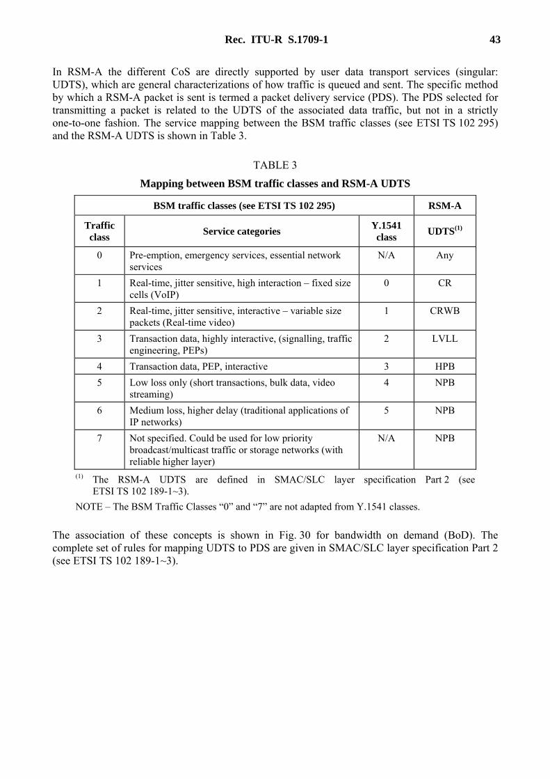
Rec. ITU-R S.1709-1 43
In RSM-A the different CoS are directly supported by user data transport services (singular: UDTS), which are general characterizations of how traffic is queued and sent. The specific method by which a RSM-A packet is sent is termed a packet delivery service (PDS). The PDS selected for transmitting a packet is related to the UDTS of the associated data traffic, but not in a strictly one-to-one fashion. The service mapping between the BSM traffic classes (see ETSI TS 102 295) and the RSM-A UDTS is shown in Table 3.
TABLE 3
Mapping between BSM traffic classes and RSM-A UDTS
BSM traffic classes (see ETSI TS 102 295) RSM-A
Traffic class Service categories Y.1541
class UDTS(1)
0 Pre-emption, emergency services, essential network services
N/A Any
1 Real-time, jitter sensitive, high interaction – fixed size cells (VoIP)
0 CR
2 Real-time, jitter sensitive, interactive – variable size packets (Real-time video)
1 CRWB
3 Transaction data, highly interactive, (signalling, traffic engineering, PEPs)
2 LVLL
4 Transaction data, PEP, interactive 3 HPB 5 Low loss only (short transactions, bulk data, video
streaming) 4 NPB
6 Medium loss, higher delay (traditional applications of IP networks)
5 NPB
7 Not specified. Could be used for low priority broadcast/multicast traffic or storage networks (with reliable higher layer)
N/A NPB
(1) The RSM-A UDTS are defined in SMAC/SLC layer specification Part 2 (see ETSI TS 102 189-1~3).
NOTE – The BSM Traffic Classes “0” and “7” are not adapted from Y.1541 classes.
The association of these concepts is shown in Fig. 30 for bandwidth on demand (BoD). The complete set of rules for mapping UDTS to PDS are given in SMAC/SLC layer specification Part 2 (see ETSI TS 102 189-1~3).

44 Rec. ITU-R S.1709-1
FIGURE 30 CoS, UDTS, and PDS relationships
4.5 Bandwidth management-resource allocation and queue management The bandwidth management function takes packets from the SLC sub-layer and identifies the appropriate PTO to transmit these packets on.
The bandwidth management function operates on the basis of queues. All outgoing packets are mapped into one of many queues, based on their destination and the associated UDTS. Each queue has an assigned PDS. Depending on the queue state for each PDS, the SMAC executes the appropriate protocol and to garner radio resources in the form of PTOs for transmitting the queue contents. When PTOs are available, the SMAC layer uses a defined algorithm to identify which queue is to be serviced on each particular PTO.
Rec. ITU-R S.1709-1 45
4.5.1 Rate-oriented sessions Rate-oriented sessions are collected into one of two common UDCs based on their priorities. The ST maintains queues on a per connection basis with an associated rate and flow-control information. Each connection that has been negotiated with the NOCC is mapped to one queue.
4.5.2 Volume-oriented sessions Volume-oriented sessions are multiplexed into one of up to four common UDC based on the destination downlink region and priority. The ST maintains queues for volume transmissions. The queues are on the basis of priorities and destination region. Packets are mapped into the appropriate queue when they are delivered from SLC to SMAC.
4.5.3 Contention-mode access Contention channels are available for use both for data transfer as well as for control signalling i.e. resource requests. The contention channels are partially statically configured and partially dynamically indicated by the network. The SMAC layer manages access to these resources as per the rules given in SMAC/SLC layer specification Part 2 (see ETSI TS 102 189-1~3).
4.5.4 Persistent aloha This is a modification of the standard slotted Aloha procedure whereby a single terminal can grab a slot in a frame or a set of frames using the Aloha protocol and then continue using it once every frame (or every set of frames) till it relinquishes the slot by not transmitting in this slot. This protocol is used for low-latency, low-volume periodic/quasi-periodic traffic such as TCP Ack packets. The initial slot acquisition is similar to the Slotted Aloha/Contention method – details are provided in SMAC/SLC layer specification Part 2 (see ETSI TS 102 189-1~3).
5 Security access module – Functional description The SAM is the primary security component of a satellite terminal. Physically it is a secure chip embedded in the terminal. The SAM contains secret key material and authenticates every RSM-A packet sent out by the terminal by generating an access control field the can be verified by other authorized components of the system. The SAM will only sign requests that are valid within the policies set forth for that particular ST. On the receive side it verifies that management messages are authentic messages from the NOCC. See SMAC/SLC layer specification Part 3 (see ETSI TS 102 189-1~3) for a complete description of this interface.
The SAM’s areas of responsibility to the RSM-A system are as follows: – authentication; – authorization protection; – registration; – usage audit.
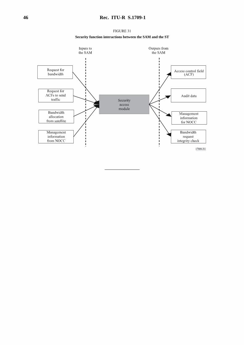
46 Rec. ITU-R S.1709-1
FIGURE 31 Security function interactions between the SAM and the ST