
TECHNICAL CATALOGUE CATALOGO TECNICO - wtk.it · come il freon, l’ammoniaca, l’acqua di mare,...
48
CATALOGO TECNICO TECHNICAL CATALOGUE
Transcript of TECHNICAL CATALOGUE CATALOGO TECNICO - wtk.it · come il freon, l’ammoniaca, l’acqua di mare,...

CATALOGO TECNICOTECHNICAL CATALOGUE

SOMMARIO / SUMMARY
4 - 18 EVAPORATORI A FASCIO TUBIERO TIPO “TUBO FORCINATO” I SHELL & TUBE EVAPORATORS TYPE “U TUBE” 18 EVAPORATORI CON ACCUMULO D’ACQUA I EVAPORATORS WITH WATER TANKS20 - 24 EVAPORATORI A FASCIO TUBIERO TIPO “TUBO DRITTO” I SHELL & TUBE EVAPORATORS TYPE “STRAIGHT TUBE”25 – 27 EVAPORATORI ALLAGATI A FASCIO TUBIERO I FLOODED EVAPORATORS 28 – 35 CONDENSATORI A FASCIO TUBIERO I SHELL&TUBE CONDENSERS36 – 41 SEPARATORI D’OLIO E RICEVITORI DI LIQUIDO I OIL SEPARATORS AND LIQUID RECEIVERS42 – 45 PIASTRE SALDO-BRASATE I BRAZED PLATES

3PRESENTAZIONE AZIENDALE COMPANY PROFILE
WTK srl, azienda leader nella costruzione di scambiatori di calore ad acqua vanta un’esperienza ultra decennale nel settore caratterizzandosi per un costante miglio-ramento tecnologico e produttivo, flessibilità di prodotto e servizio al cliente. I nostri prodotti possono essere certificati secondo le direttive CE (PED) e DNV-GL. La nostra azienda ha come missione l’evoluzione dei suoi prodotti e la crescita nei mercati Italiano ed internazionale mettendo a disposizione una vasta gamma di prodotti destinati a costruttori, rivenditori, installatori, dimensionati per impianti commerciali ed industriali e per fluidi, sempre che compatibili con i materiali usati, come il freon, l’ammoniaca, l’acqua di mare, le miscele incongelabili, l’olio, ecc. WTK srl è un’azienda certificata ISO 9001 e PED 2014/68/UE. E’ dotata di un labora-torio interno per prove e ricerche ed ai clienti mette a disposizione aggiornati stru-menti di vendita quali cataloghi dettagliati ed un sofisticato programma di calcolo (Avogadro) direttamente scaricabili dal sito web www.wtk.itLa gamma di produzione (evaporatori a fascio tubiero ad espansione secca ed alla-gati, condensatori a fascio tubiero anche per uso marino, piastre saldobrasate, se-paratori d’olio, ricevitori di liquido, raffreddatori d’olio, economizzatori, desurriscal-datori) adatta per applicazioni relative al condizionamento dell’aria, refrigerazione commerciale ed industriale, applicazioni di processo, pompe di calore, recupero di calore ed altre, consiste in scambiatori di calore a fascio tubiero per potenze da circa 20 kW a 2500 kW, piastre saldobrasate per potenze da circa 5 kW a 400 kW, sepa-ratori d’olio mono e bi-stadio per volumi d’aspirazione oltre 2500 m3/h, ricevitori di liquido orizzontali e verticali da circa 30 litri ad oltre 1000 litri.
WTK srl, leading manufacturer of water heat exchangers has an ultra-decades old experience in this field distinguishing itself for a continuous technological and ma-nufacturing improvement, product flexibility and service to cutomers. Our products can be certified in accordance with the pressure vessel directives CE (PED) and DNV-GL. Our company’s mission is the evolution of its heat exchangers and the growth in the Italian and international markets by offering to o.e.m.s, dealers, installators, a wide range of products designed for commercial and industrial plants and for fluids, if compatible with the materials, such as freon, ammonia, sea water, anti-freezing mixtures, oil, etc. WTK srl is a certified company ISO 9001 and PED 2014/68/UE. It has a laboratory for test and research and it makes available to the clients updated sales tools such as detailed product catalogues and a sophisticated calculation programme (Avogadro) which can be downloaded from the website www.wtk.itThe range of products (shell & tube evaporators dry-expansion and flooded type, shell & tube condensers also for maritime application, brazed plates, oil separa-tors, liquid receivers, oil coolers, economizers, desuperheaters) is suitable for ap-plications related to the air conditioning, commercial and industrial refrigeration, process, heat pumps, heat recovery and others. It consists of heat exchangers shell & tube type suitable for capacities from about 20 kW to 2500 kW, brazed plates for capacities from about 5 kW to 400 kW, oil separators single and double stage for suction volumes beyond 2500 m3/h, horizontal and vertical liquid receivers from about 30 litres to 1000 litres and over.
WTK Catalogo Tecnico - Technical Catalogue

4 EVAPORATORI A FASCIO TUBIERO TIPO “TUBO FORCINATO”SHELL & TUBE EVAPORATORS TYPE “U TUBE”
WTK Catalogo Tecnico - Technical Catalogue
5EVAPORATORI A FASCIO TUBIERO TIPO “TUBO FORCINATO”SHELL & TUBE EVAPORATORS TYPE “U TUBE”
EVAPORATORI A FASCIO TUBIERO TIPO “TUBO FORCINATO”SHELL & TUBE EVAPORATORS TYPE “U TUBE”
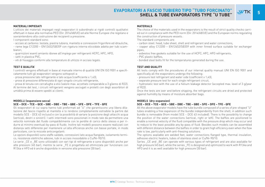
MATERIALI IMPIEGATIL’utilizzo dei materiali impiegati negli evaporatori è subordinato ai rigidi controlli qualitativi effettuati in base alla normativa PED (Dir. 2014/68/UE) ed alle Norme Europee che regolano e sovraintendono alla costruzione dei recipienti a pressione.I componenti standard sono:- acciaio al carbonio: testata, piastra tubiera, mantello e connessioni frigorifere ed idrauliche,- rame lega C12200 – EN12452/SB359 con rigatura interna elicoidale adatta per tubi scam-biatori, - guarnizioni esenti amianto idonee all’impiego per refrigeranti HCFC, HFC, HFO,- setti in plastica PVC,- viti di fissaggio conformi alle temperature di utilizzo in acciaio legato.
TEST E QUALITA’I controlli vengono effettuati in base al manuale interno di qualità UNI EN ISO 9001 e specifi-catamente tutti gli evaporatori vengono sottoposti a:- prova pressione lato refrigerante e lato acqua (coefficiente x 1,43),- prova di pressione differenziata di ogni singolo circuito refrigerante,- prova di tenuta con cercafughe a elio (valore max. accettato comparabile a 3 g/anno di R22).Al termine del test, i circuiti refrigeranti vengono asciugati e protetti con degli assorbitori di umidità prima di essere spediti ai clienti.
MODELLI (espansione secca) SCE – DCE – TCE – QCE – SBE – DBE – TBE – QBE – SFE – DFE – TFE - QFE Gli evaporatori di cui sopra hanno tubi preformati ad “U” che garantiscono una libera dila-tazione del fascio rispetto al mantello e lo rendono completamente estraibile (a partire dal modello SCE – DCE 63 incluso) e con la possibilità di variare la posizione degli attacchi acqua (verticali, destri o sinistri). I setti intermedi sono posizionati in modo tale da permettere una velocità nominale del fluido compatibilmente con le perdite di carico dello stesso e per ri-durre al minimo eventuali by-pass di fluido. Inoltre tali modelli possono essere realizzati con distanza setti differente per mantenere un’alta efficienza anche con basse portate, in modo particolare, con le miscele anticongelanti.Le opzioni disponibili sono staffe saldate, connessioni lato acqua flangiate, isolamento termi-co, resistenze elettriche adesive, tubi in acciaio inossidabile o Cu/Ni-90/10.Le serie _CE e _BE sono utilizzabili con vari tipi di refrigerante e sono disponibili anche per alte pressioni (45 bar), mentre la serie _FE è progettata ed ottimizzata per funzionare con R134a e HFO ed è anche disponibile in versione alta pressione (30 bar).
MATERIALSThe choice of the materials used in the evaporators is the result of strict quality checks carri-ed out in compliance with the PED norm (Dir. 2014/68/UE) and the European norms regulating the construction of pressure vessels.The standard components are:- carbon steel: head, tube sheet, shell and refrigerant and water connections,- copper alloy C12200 – EN12452/SB359 with inner finned surface suitable for exchanger pipes, - asbestos free gaskets suitable for the use of HCFC, HFC, HFO refrigerants,- PVC plastic baffles,- bonded steel bolts fit for the temperatures generated during the use.
TEST AND QUALITYAll tests comply with the procedures of our internal quality manual UNI EN ISO 9001 and specifically all the evaporators undergo the following:- pressure test refrigerant and water side (coefficient x 1,43),- separate pressure test for each single refrigerant circuit,- hydrostatic test with the use of a helium leakage detector (accepted max. level of 3 g/year of R22).Once the tests are over and before shipping, the refrigerant circuits are dried and protected against humidity by means of moisture absorber bags.
MODELS (dry-expansion) SCE – DCE – TCE – QCE – SBE – DBE – TBE – QBE – SFE – DFE – TFE - QFE All the above evaporator models have the tube bundle composed of a series of pre-shaped “U” tubes enabling a free expansion of the bundle independently from the shell; in addition such bundle is removable (from model SCE – DCE 63 included). There is the possibility to change the position of the water connections (vertical, right or left). The baffles are positioned to enable a nominal velocity of the fluid compatible with the pressure drop which may occur and to reduce to the least possible any by-pass of fluid. Besides such models can be assembled with different distance between the baffles in order to grant high efficiency even when the flow rate is low, particularly with anti-freezing solutions.The options available are welded feet, water connections flanged type, thermal insulation, adhesive electric heaters, tubes of stainless steel or Cu/Ni-90/10.Series _CE and _BE can operate with various types of refrigerant and are also available for high pressure (45 bar), while the series _FE is designed and optimized to work with R134a and HFO and it is as well available for high pressure (30 bar).
WTK Catalogo Tecnico - Technical Catalogue

6 EVAPORATORI A FASCIO TUBIERO TIPO “TUBO FORCINATO”SHELL & TUBE EVAPORATORS TYPE “U TUBE”
INSTALLAZIONE ED APPLICAZIONE DEGLI EVAPORATORI A FASCIO TUBIEROPer una corretta applicazione dei nostri evaporatori a fascio tubiero è necessario rispettare delle semplici precauzioni:Montare l’evaporatore in posizione orizzontale.Non invertire l’ingresso con l’uscita dell’acqua per non penalizzare la resa dell’evaporatore o provocare il rischio di vibrazioni eccessive del fascio interno.Non sottoporre l’evaporatore a vibrazioni eccessive.Evitare l’ingresso di corpi estranei nel circuito idraulico prevedendo appositi filtri con larghezza maglia max. 1,5mm.Analizzare le acque verificandone la compatibilità con i materiali dello scambiatore prima di utilizzare l’evaporatore (soprattutto in circuiti aperti).Impiegare sempre acque o soluzioni incongelabili inibite e compatibili con i materiali dell’evaporatore, ve-rificarle nel tempo e non operare con temperature vicine al punto di congelamento, altrimenti aumentare la percentuale di anticongelante.Evitare l’uso con acque contenenti cloro (max. = 3 p.p.m.) nel caso di materiali standardEvitare di superare le portate max. “Mm” riportate a catalogo, causa di eccessive vibrazioniIn fase di riempimento del circuito idrico, fare attenzione a scaricare completamente l’aria presente nel mantello.Fare attenzione a scaricare completamente l’aria dal circuito e dall’evaporatore, verificando l’esistenza di una adeguata contropressione all’uscita acqua dell’evaporatore in modo da non lasciare lo scarico libero e di creare quindi all’interno dell’evaporatore stesso una perdita di carico almeno uguale a quella di catalogo o calcolo (se a circuito aperto installare all’uscita acqua una valvola di regolazione e taratura).Per evitare la formazione di ghiaccio, consigliamo un approccio di 5K con una temperatura di evapora-zione non inferiore a -1°C.Non lavorare con un surriscaldamento < 3K per garantire una completa evaporazione del gas. Lasciare l’evaporatore completamente pieno d’acqua o totalmente vuoto in caso di lunghe fermateIn caso di svuotamento verificare che tutta l’acqua sia completamente drenata; non lasciare mai l’evapo-ratore parzialmente pieno.Evitare, a circuito aperto, che durante la fermata della pompa l’evaporatore si svuotiEvitare la cavitazione della pompa e la presenza di gas nel circuito idraulicoNon prevedere parzializzazioni (lato refrigerante) che scendano al di sotto del 50% della potenza totale del compressore, eventualmente contattare WTK.
INSTALLATION AND APPLICATION OF THE SHELL & TUBE EVAPORATORSFor a correct functioning of our shell & tube evaporators it is necessary to follow some simple pre-cau-tions:Install the evaporator in horizontal position.Do not reverse the water inlet and outlet in order not to decrease the evaporator performance or cause excessive vibrations of the tube bundle.Do not expose the evaporator to excessive vibrations.Avoid foreign particles to enter into the water circuit by applying suitable filters with a mesh size of max. 1,5mm.Analyze the water checking its compatibility with the materials of the heat exchanger before using the evaporator (especially in open circuits).Always use waters or anti-freezing inhibited mixtures compatible with the materials of the evaporator, check the fluids from time to time and do not run the unit with temperatures near the freezing point, otherwise increase the percentage of anti-freezing.Avoid the use of the evaporator with waters containing chlorine (max. = 3 p.p.m.) when the unit is manu-factured with standard materials.Avoid exceeding the max. flow rate “Mm” shown in the catalogue, as this may cause excessive vibrationsDuring the filling of the water circuit, pay attention to discharge totally the air in the shell.Pay attention to discharge all the air from the circuit and evaporator, checking the presence of an adequa-te counter-pressure at the water outlet of the evaporator so not to let the drain free and to cause inside the evaporator a pressure drop at least equal to the catalogue or calculation one (if in open circuit it is better to install at the water outlet a regulation and calibration valve).In order to avoid the ice formation, we advise a temperature approach of 5K with an evaporation tempe-rature not less than -1°C.Do not operate with a superheating < 3K in order to guarantee a complete gas evaporation .Leave the evaporator totally full of water or totally empty if not in operation for long time.In case the shell needs to be emptied be sure that all the water is completely drained; never leave the evaporator partially loaded with water.Avoid, in open circuit, the water drainage of the evaporator during the pump stop.Avoid the cavitation of the pump and the presence of gas in the hydraulic circuit.Do not set partial loads (refrigerant side) lower than 50% of the total duty of the compressor, if necessary contact WTK.
Nella tabella sottostante vengono riportate, in funzione del punto di congelamento, le percentuali in peso delle principali miscele anticongelanti.The table herebelow shows, as function of the freezing point, the percentages in weight of the main anti-freezing mixtures.
SUGGERIMENTI DI CORRETTA SELEZIONENegli evaporatori a fascio tubiero, depositi di sostanze all’esterno dei tubi tra i setti sono un effetto di cui si deve necessariamente tenere conto in fase di selezione del prodotto. Il fattore di sporcamento (f. f.) è quindi elemento fondamentale per il dimensionamento corretto di un evaporatore. Si suggerisce la scelta del giusto valore in base ai seguenti parametri.SUGGESTIONS FOR A CORRECT SELECTIONIn the shell & tube evaporators, deposits of various substances external to the tubes between the baffles are an effect that must necessarily be considered when selecting the product. The fouling factor (f. f.) is thus a fundamental value for a correct choice of an evaporator. We therefore advise to choose the right value based on the following parametres. Acqua dolce normale in circuito chiuso - Normal fresh water in closed circuit f.f.= 0.000043 m2 K/WAcqua di circuito aperto - Water in open circuit f.f. = 0,000086 m2 K/WSoluzioni contenenti glicole < 40% - Glycol solutions < 40% f.f. = 0,000086 m2 K/WSoluzioni contenenti glicole > 40% - Glycol solutions > 40% f.f. = 0,000172 m2 K/W
PUNTO DI CONGELAMENTO
FREEZING POINTGLICOLE ETILENICO
ETHYLEN GLYCOLGLICOLE PROPILENICO
PROPYLEN GLYCOLTYFOXITTYFOXIT
°C % (massica - mass) % (massica - mass) % (g/cm3)-10 24 24 40 (1.10)-20 36 36 50 (1.15)-30 46 46 68 (1.17)-40 53 53 80 (1.20)
SCE = 1 CIRCUITO REFRIGERANTESCE = 1 REFRIGERANT CIRCUIT
WTK Catalogo Tecnico - Technical Catalogue

7EVAPORATORI A FASCIO TUBIERO TIPO “TUBO FORCINATO”SHELL & TUBE EVAPORATORS TYPE “U TUBE”
EVAPORATORI A FASCIO TUBIERO TIPO “TUBO FORCINATO”SHELL & TUBE EVAPORATORS TYPE “U TUBE”
MODELLO MODEL A B C D E F G H K R S T U d1 d2 d3
Portata Max.
Flow Rate Max.
Vr Vw Cat. PED
Peso (Vuoto) Weight (Empty)
mm mm mm mm mm mm mm mm mm mm mm mm mm Thrd/Vict mm mm m3/h dm3 dm3 Gr. 1-2 kg
SCE 23-4P * 690 840 140 100 130 195 30 35 30 550 60 160 - 1.1/2” Rtlk 1” - ODS 16 Rtlk 1.3/4” - ODS 28 6,2 3,5 6,3 II 32SCE 33-4P * 840 990 140 100 130 195 30 35 30 650 60 160 - 1.1/2” Rtlk 1” - ODS 16 Rtlk 1.3/4” - ODS 28 7,5 4,2 7,5 II 36SCE 43-4P * 1040 1260 140 108 130 195 30 35 30 800 60 160 - 2” Rtlk 1” - ODS 16 Rtlk 1.3/4” - ODS 28 10,5 5,1 9,3 II 41SCE 53-4P * 1190 1410 140 108 130 195 30 35 30 950 60 160 - 2” Rtlk 1” - ODS 16 Rtlk 1.3/4” - ODS 28 10,8 5,8 10,5 II 46SCE 63-4P 1030 1270 168 156 130 245 45 37 30 800 60 160 - 2.1/2” Rtlk 1.1/4” - ODS 22 ODS 42 11,2 7,2 15,1 III 65SCE 73-4P 1180 1420 168 156 130 245 45 37 30 950 60 160 - 2.1/2” Rtlk 1.1/4” - ODS 22 ODS 42 14,8 8,1 17,1 III 70SCE 83-4P 1380 1620 168 156 130 245 45 37 30 1100 60 160 - 2.1/2” Rtlk 1.1/4” - ODS 22 ODS 42 15,4 9,2 19,6 III 75
SCE 103-4P 1530 1770 168 156 130 245 45 37 30 1200 60 160 - 2.1/2” Rtlk 1.1/4” - ODS 22 ODS 42 18,4 10,1 21,5 III 80SCE 133 1530 1810 194 178 130 270 50 45 30 1200 60 160 - 3” Rtlk 1.3/4” - ODS 35 ODS 54 20,2 14,0 29,1 III 105SCE 143 1830 2115 194 178 130 270 50 45 30 1500 60 160 - 3” Rtlk 1.3/4” - ODS 35 ODS 54 26,2 16,4 34,2 III 116SCE 163 2030 2310 194 178 130 270 50 45 30 1700 60 160 - 3” Rtlk 1.3/4” - ODS 35 ODS 54 29,5 18,2 37,3 III 123SCE 203 2000 2320 219 200 150 310 55 46 - 1600 80 260 100 DN 100 Rtlk 1.3/4” - ODS 35 ODS 64 41 23,8 47,8 III 155SCE 243 2300 2620 219 200 150 310 55 46 - 1800 80 260 100 DN 100 Rtlk 1.3/4” - ODS 35 ODS 64 47,9 26,9 43,8 III 168SCE 293 2280 2660 273 240 150 370 60 60 - 1800 100 300 100 DN 125 ODS 42 ODS 64 81,9 34,1 94,2 IV 260SCE 343 2280 2660 273 240 150 370 60 60 - 1800 100 300 100 DN 125 ODS 42 ODS 64 81,9 38,1 89,0 IV 270SCE 393 2280 2660 273 240 150 370 60 60 - 1800 100 300 100 DN 125 ODS 42 ODS 64 81,9 43,9 81,6 IV 282SCE 453 2250 2700 324 276 200 420 75 70 - 1800 100 300 100 DN 150 ODS 42 ODS 80 117,6 52,1 132,1 IV 346SCE 513 2250 2700 324 276 200 420 75 70 - 1800 100 300 100 DN 150 ODS 42 ODS 80 117,6 59,0 123,2 IV 361SCE 583 2250 2700 324 276 200 420 75 70 - 1800 100 300 100 DN 150 ODS 42 ODS 80 117,6 67,8 112,0 IV 380SCE 673 2200 2740 406 330 200 510 90 80 - 1800 120 400 100 DN 200 ODS 54 ODS 105-108 142,1 78,3 219,9 IV 575SCE 783 2200 2740 406 330 200 510 90 80 - 1800 120 400 100 DN 200 ODS 54 ODS 105-108 142,1 90,6 204,2 IV 600SCE 923 2200 2740 406 330 200 510 90 80 - 1800 120 400 100 DN 200 ODS 54 ODS 105-108 189 108,4 181,3 IV 645
SCE 1053 2700 3240 406 330 200 510 90 80 - 1800 120 400 100 DN 200 ODS 54 ODS 105-108 231,5 128,6 216,3 IV 645
SCE = 1 CIRCUITO REFRIGERANTESCE = 1 REFRIGERANT CIRCUIT
* FASCIO TUBIERO NON ESTRAIBILE* TUBE BUNDLE NOT REMOVABLE
LIMITI DI IMPIEGO - WORKING LIMITS
SERIE CE T Pr Prp Pw Pwp
[°C] [bar] [bar] [bar] [bar]
STD -10 / +90 30 42,9 10 14,3
L (Low Temp) -45 / +50 20 28,6 10 14,3
HP -10 / +90 45 64,4 15 21,5
WTK Catalogo Tecnico - Technical Catalogue

8 EVAPORATORI A FASCIO TUBIEROSHELL&TUBE EVAPORATORS
DCE = 2 CIRCUITI REFRIGERANTIDCE = 2 REFRIGERANT CIRCUITS
* FASCIO TUBIERO NON ESTRAIBILE* TUBE BUNDLE NOT REMOVABLE
MODELLO MODEL A B C D E F G H K M R S T U d1 d2 d3
Portata Max.
Flow Rate Max.
Vr Vw Cat. PED
Peso (Vuoto) Weight (Empty)
mm mm mm mm mm mm mm mm mm mm mm mm mm mm Thrd/Vict mm mm m3/h dm3 dm3 Gr. 1-2 kg
DCE 43-4P * 1040 1208 140 108 130 195 53 17 40 90 800 60 160 - 2” ODS 18 - Ø21,3 ODS 28 - Ø33,7 10,5 5,1 9,3 II 41DCE 53-4P * 1190 1360 140 108 130 195 53 17 40 90 950 60 160 - 2” ODS 18 - Ø21,3 ODS 28 - Ø33,7 10,8 5,8 10,5 II 46DCE 63-4P 1030 1270 168 156 130 245 65 25 70 80 800 60 160 - 2.1/2” Rtlk 1.1/4” - ODS 22 Rtlk 1.3/4” - ODS 35 11,2 7,2 15,1 II 65DCE 73-4P 1180 1420 168 156 130 245 65 25 70 80 950 60 160 - 2.1/2” Rtlk 1.1/4” - ODS 22 Rtlk 1.3/4” - ODS 35 14,8 8,1 17,1 II 70DCE 83-4P 1380 1620 168 156 130 245 65 25 70 80 1100 60 160 - 2.1/2” Rtlk 1.1/4” - ODS 22 Rtlk 1.3/4” - ODS 35 15,4 9,2 19,6 II 75
DCE 103-4P 1530 1770 168 156 130 245 65 25 70 80 1200 60 160 - 2.1/2” Rtlk 1.1/4” - ODS 22 Rtlk 1.3/4” - ODS 35 18,4 10,1 21,5 II 80DCE 133 1530 1810 194 178 130 270 34 28 70 84 1200 60 160 - 3” Rtlk 1.1/4” - ODS 22 ODS 42 25,2 14,0 29,1 III 105DCE 143 1830 2110 194 178 130 270 34 28 70 84 1500 60 160 - 3” Rtlk 1.1/4” - ODS 22 ODS 42 26,2 16,4 34,2 III 116DCE 163 2030 2310 194 178 130 270 34 28 70 84 1700 60 160 - 3” Rtlk 1.1/4” - ODS 22 ODS 42 29,5 18,2 37,3 III 123DCE 203 2000 2320 219 200 150 310 49 31 84 92 1600 80 260 100 DN 100 Rtlk 1.3/4” - ODS 35 ODS 54 41 23,8 47,8 III 155DCE 243 2300 2620 219 200 150 310 49 31 84 92 1800 80 260 100 DN 100 Rtlk 1.3/4” - ODS 35 ODS 54 47,9 26,9 43,8 III 168DCE 293 2280 2660 273 240 150 370 60 40 104 112 1800 100 300 100 DN 125 Rtlk 1.3/4” - ODS 35 ODS 64 81,9 34,1 94,2 III 260DCE 343 2280 2660 273 240 150 370 60 40 104 112 1800 100 300 100 DN 125 Rtlk 1.3/4” - ODS 35 ODS 64 81,9 38,1 89,0 III 270DCE 393 2280 2660 273 240 150 370 60 40 104 112 1800 100 300 100 DN 125 Rtlk 1.3/4” - ODS 35 ODS 64 81,9 43,9 81,6 III 282DCE 453 2250 2700 324 276 200 420 60 60 120 130 1800 100 300 100 DN 150 Rtlk 1.3/4” - ODS 35 ODS 64 117,6 52,1 132,1 III 346DCE 513 2250 2700 324 276 200 420 60 60 120 130 1800 100 300 100 DN 150 Rtlk 1.3/4” - ODS 35 ODS 64 117,6 59,0 123,2 III 361DCE 583 2250 2700 324 276 200 420 60 60 120 130 1800 100 300 100 DN 150 Rtlk 1.3/4” - ODS 35 ODS 64 117,6 67,8 112,0 IV 380DCE 673 2200 2740 406 330 200 510 75 70 140 196 1800 120 400 100 DN 200 ODS 42 ODS 80 142,1 78,3 219,9 IV 575DCE 783 2200 2740 406 330 200 510 75 70 140 196 1800 120 400 100 DN 200 ODS 42 ODS 80 142,1 90,6 204,2 IV 600DCE 923 2200 2740 406 330 200 510 75 70 140 196 1800 120 400 100 DN 200 ODS 42 ODS 80 189 108,4 181,3 IV 645
DCE 1053 2700 3240 406 330 200 510 75 70 140 196 2200 120 400 100 DN 200 ODS 42 ODS 80 231,5 128,6 216,3 IV 722DCE 1133 2700 3260 457 352 200 510 75 70 140 196 2200 120 400 100 DN 200 ODS 42 ODS 80 261 154,0 286,3 IV 850DCE 1223 2700 3260 457 352 200 510 75 70 140 196 2200 120 400 100 DN 200 ODS 42 ODS 80 261 159,2 279,6 IV 865DCE 1373 2700 3280 508 361 200 620 110 120 170 240 2200 120 500 100 DN 200 ODS 54 ODS 105-108 285,5 176,0 381,7 IV 1000DCE 1533 2700 3280 508 361 200 620 110 120 170 240 2200 120 500 100 DN 200 ODS 54 ODS 105-108 285,5 198,2 353,2 IV 1040DCE 1583 2700 3280 508 361 200 620 110 120 170 240 2200 120 500 100 DN 200 ODS 54 ODS 105-108 285,5 208,0 340,6 IV 1080
LIMITI DI IMPIEGO - WORKING LIMITS
SERIE CE T Pr Prp Pw Pwp
[°C] [bar] [bar] [bar] [bar]
STD -10 / +90 30 42,9 10 14,3
L (Low Temp) -45 / +50 20 28,6 10 14,3
HP -10 / +90 45 64,4 15 21,5
WTK Catalogo Tecnico - Technical Catalogue

9EVAPORATORI A FASCIO TUBIEROSHELL&TUBE EVAPORATORS
* FASCIO TUBIERO NON ESTRAIBILE* TUBE BUNDLE NOT REMOVABLE
LIMITI DI IMPIEGO - WORKING LIMITS
SERIE CE T Pr Prp Pw Pwp
[°C] [bar] [bar] [bar] [bar]
STD -10 / +90 30 42,9 10 14,3
L (Low Temp) -45 / +50 20 28,6 10 14,3
HP -10 / +90 45 64,4 15 21,5
EVAPORATORI A FASCIO TUBIEROSHELL&TUBE EVAPORATORS
TCE = 3 CIRCUITI REFRIGERANTITCE = 3 REFRIGERANT CIRCUITS
MODELLO MODEL A B C D E F G H K I L M R S T U d1 d2 d3
Portata Max.
Flow Rate Max.
Vr Vw Cat. PED
Peso (Vuoto) Weight (Empty)
mm mm mm mm mm mm mm mm mm mm mm mm mm mm mm mm Thrd/Vict mm mm m3/h dm3 dm3 Gr. 1-2 kg
TCE 133 1530 1810 194 176 130 270 30 30 50 40 43 60 1200 60 160 - 3” ODS 22 - Ø26,9 ODS 35 - Ø42,4 25,2 14,0 29,1 II 105
TCE 143 1830 2110 194 176 130 270 30 30 50 40 43 60 1500 60 160 - 3” ODS 22 - Ø26,9 ODS 35 - Ø42,4 26,2 16,4 34,2 II 116
TCE 163 2030 2310 194 176 130 270 30 30 50 40 43 60 1700 60 160 - 3” ODS 22 - Ø26,9 ODS 35 - Ø42,4 29,5 18,2 37,3 II 123
TCE 203 2000 2315 219 200 150 310 35 35 65 55 65 65 1600 80 260 100 DN 100 Rtlk 1.1/4” - ODS 22 ODS 42 - Ø48,3 41 23,8 47,8 III 155
TCE 243 2300 2615 219 200 150 310 35 35 65 55 65 65 1800 80 260 100 DN 100 Rtlk 1.1/4” - ODS 22 ODS 42 - Ø48,3 47,9 26,9 43,8 III 168
TCE 293 2280 2650 273 236 150 370 45 45 81 60 70 81 1800 100 300 100 DN 125 ODS 35 ODS 54 81,9 34,1 94,2 III 260
TCE 343 2280 2650 273 236 150 370 45 45 81 60 70 81 1800 100 300 100 DN 125 ODS 35 ODS 54 81,9 38,1 89,0 III 270
TCE 393 2280 2650 273 236 150 370 45 45 81 60 70 81 1800 100 300 100 DN 125 ODS 35 ODS 54 81,9 43,9 81,6 III 282
TCE 453 2250 2695 324 276 200 420 55 55 95 80 80 95 1800 100 300 100 DN 150 ODS 35 ODS 54 117,6 52,1 132,1 III 346
TCE 513 2250 2695 324 276 200 420 55 55 95 80 80 95 1800 100 300 100 DN 150 ODS 35 ODS 54 117,6 59,0 123,2 III 361
TCE 583 2250 2695 324 276 200 420 55 55 95 80 80 95 1800 100 300 100 DN 150 ODS 35 ODS 54 117,6 67,8 112,0 III 380
TCE 673 2200 2740 406 330 200 510 70 70 120 110 110 120 1800 120 400 100 DN 200 ODS 42 ODS 80 142,1 78,3 219,9 III 575
TCE 783 2200 2740 406 330 200 510 70 70 120 110 110 120 1800 120 400 100 DN 200 ODS 42 ODS 80 142,1 90,6 204,2 III 600
TCE 923 2200 2740 406 330 200 510 70 70 120 110 110 120 1800 120 400 100 DN 200 ODS 42 ODS 80 189 108,4 181,3 IV 645
TCE 1053 2700 3240 406 330 200 510 70 70 120 110 110 120 2200 120 400 100 DN 200 ODS 42 ODS 80 231,5 128,6 216,3 IV 722
TCE 1133 2700 3250 457 352 200 510 70 70 120 110 110 120 2200 120 400 100 DN 200 ODS 42 ODS 80 261 154,0 286,3 IV 850
TCE 1223 2700 3250 457 352 200 510 70 70 120 110 110 120 2200 120 400 100 DN 200 ODS 42 ODS 80 261 159,2 279,6 IV 865
TCE 1373 2700 3280 508 362 200 620 95 95 140 95 155 160 2200 120 500 100 DN 200 ODS 42 ODS 80 285,5 176,0 381,7 IV 1000
TCE 1533 2700 3280 508 362 200 620 95 95 140 95 155 160 2200 120 500 100 DN 200 ODS 42 ODS 80 285,5 198,2 353,2 IV 1040
TCE 1583 2700 3280 508 362 200 620 95 95 140 95 155 160 2200 120 500 100 DN 200 ODS 42 ODS 80 285,5 208,0 340,6 IV 1080
WTK Catalogo Tecnico - Technical Catalogue

10 EVAPORATORI A FASCIO TUBIEROSHELL&TUBE EVAPORATORS
QCE = 4 CIRCUITI REFRIGERANTIQCE = 4 REFRIGERANT CIRCUITS
MODELLO MODEL A B C D E F G H K I L M N O P R S T U d1 d2 d3
Portata Max.
Flow Rate Max.
Vr Vw Cat. PED
Peso (Vuoto) Weight (Empty)
mm mm mm mm mm mm mm mm mm mm mm mm mm mm mm mm mm mm mm Thrd/Vict mm mm m3/h dm3 dm3 Gr. 1-2 kg
QCE 203 2000 2320 219 200 150 310 42 34 21 50 80 32 75 75 - 1600 80 260 100 DN 100 ODS 22 - Ø26,9 ODS 35 - Ø42,4 41 23,8 47,8 II 155
QCE 243 2300 2320 219 200 150 310 42 34 21 50 80 32 75 75 - 1600 80 260 100 DN 100 ODS 22 - Ø26,9 ODS 35 - Ø42,4 47,9 26,9 43,8 III 168
QCE 293 2280 2660 273 240 150 370 50 43 25 60 50 25 90 90 90 1800 100 300 100 DN 125 ODS 22 - Ø26,9 ODS 42 - Ø48,3 81,9 34,1 94,2 III 260
QCE 343 2280 2660 273 240 150 370 50 43 25 60 50 25 90 90 90 1800 100 300 100 DN 125 ODS 22 - Ø26,9 ODS 42 - Ø48,3 81,9 38,1 89,0 III 270
QCE 393 2280 2660 273 240 150 370 50 43 25 60 50 25 90 90 90 1800 100 300 100 DN 125 ODS 22 - Ø26,9 ODS 42 - Ø48,3 81,9 43,9 81,6 III 282
QCE 453 2250 2700 324 276 200 420 31 70 31 31 70 42 110 125 - 1800 100 300 100 DN 150 ODS 35 ODS 54 117,6 52,1 132,1 III 346
QCE 513 2250 2700 324 276 200 420 31 70 31 31 70 42 110 125 - 1800 100 300 100 DN 150 ODS 35 ODS 54 117,6 59,0 123,2 III 361
QCE 583 2250 2700 324 276 200 420 31 70 31 31 70 42 110 125 - 1800 100 300 100 DN 150 ODS 35 ODS 54 117,6 67,8 112,0 III 380
QCE 673 2200 2740 406 330 200 510 70 50 39 100 100 47 140 140 - 1800 120 400 100 DN 200 ODS 35 ODS 64 142,1 78,3 219,9 III 575
QCE 783 2200 2740 406 330 200 510 70 50 39 100 100 47 140 140 - 1800 120 400 100 DN 200 ODS 35 ODS 64 142,1 90,6 204,2 III 600
QCE 923 2200 2740 406 330 200 510 70 50 39 100 100 47 140 140 - 1800 120 400 100 DN 200 ODS 35 ODS 64 189 108,4 181,3 III 645
QCE 1053 2700 3240 406 330 200 510 70 50 39 100 100 47 140 140 - 2200 120 400 100 DN 200 ODS 35 ODS 64 231,5 128,6 216,3 III 722
QCE 1133 2700 3260 457 352 200 510 70 50 39 100 100 47 140 140 - 2200 120 400 100 DN 200 ODS 35 ODS 64 261 154,0 286,3 IV 850
QCE 1223 2700 3260 457 352 200 510 70 50 39 100 100 47 140 140 - 2200 120 400 100 DN 200 ODS 35 ODS 64 261 159,2 279,6 IV 865
QCE 1373 2700 3250 508 361 200 620 110 85 59 85 110 59 177 177 - 2200 120 500 100 DN 200 ODS 42 ODS 80 285,5 176,0 381,7 IV 1000
QCE 1533 2700 3250 508 361 200 620 110 85 59 85 110 59 177 177 - 2200 120 500 100 DN 200 ODS 42 ODS 80 285,5 198,2 353,2 IV 1040
QCE 1583 2700 3250 508 361 200 620 110 85 59 85 110 59 177 177 - 2200 120 500 100 DN 200 ODS 42 ODS 80 285,5 208,0 340,6 IV 1080
LIMITI DI IMPIEGO - WORKING LIMITS
SERIE CE T Pr Prp Pw Pwp
[°C] [bar] [bar] [bar] [bar]
STD -10 / +90 30 42,9 10 14,3
L (Low Temp) -45 / +50 20 28,6 10 14,3
HP -10 / +90 45 64,4 15 21,5
WTK Catalogo Tecnico - Technical Catalogue

11EVAPORATORI A FASCIO TUBIEROSHELL&TUBE EVAPORATORS
LIMITI DI IMPIEGO - WORKING LIMITS
SERIE BE T Pr Prp Pw Pwp
[°C] [bar] [bar] [bar] [bar]
STD -10 / +90 30 42,9 10 14,3
L (Low Temp) -45 / +50 20 28,6 10 14,3
HP -10 / +90 45 64,4 15 21,5
EVAPORATORI A FASCIO TUBIEROSHELL&TUBE EVAPORATORS
SBE = 1 CIRCUITO REFRIGERANTESBE = 1 REFRIGERANT CIRCUIT
MODELLO MODEL A B C D E F G H R S T U d1 d2 d3
Portata Max.
Flow Rate Max.
Vr Vw Cat. PED
Peso (Vuoto) Weight (Empty)
mm mm mm mm mm mm mm mm mm mm mm mm Thrd/Vict mm mm m3/h dm3 dm3 Gr. 1-2 kg
SBE 165 1500 1820 219 200 130 310 55 46 1200 80 300 - 3” ODS 35 ODS 54 25,8 18,4 37,2 III 131
SBE 195 1500 1920 273 236 150 370 60 60 1200 100 300 100 DN 100 ODS 42 ODS 64 44,5 23,9 65,9 III 213
SBE 235 1500 1920 273 236 150 370 60 60 1200 100 300 100 DN 100 ODS 42 ODS 64 44,5 26,6 62,4 III 219
SBE 265 1500 1920 273 236 150 370 60 60 1200 100 300 100 DN 100 ODS 42 ODS 64 44,5 30,5 57,4 III 224
SBE 385 1730 2180 324 276 200 420 75 70 1400 100 300 100 DN 150 ODS 42 ODS 80 93,5 41,2 105,5 IV 327
SBE 415 1730 2180 324 276 200 420 75 70 1400 100 300 100 DN 150 ODS 42 ODS 80 93,5 46,8 98,3 IV 347
SBE 495 1730 2180 324 276 200 420 75 70 1400 100 300 100 DN 150 ODS 42 ODS 80 93,5 53,8 89,3 IV 361
WTK Catalogo Tecnico - Technical Catalogue

12 EVAPORATORI A FASCIO TUBIEROSHELL&TUBE EVAPORATORS
DBE = 2 CIRCUITI REFRIGERANTIDBE = 2 REFRIGERANT CIRCUITS
MODELLO MODEL A B C D E F G H K M R S T U d1 d2 d3
Portata Max.
Flow Rate Max.
Vr Vw Cat. PED
Peso (Vuoto) Weight (Empty)
mm mm mm mm mm mm mm mm mm mm mm mm mm mm Thrd/Vict mm mm m3/h dm3 dm3 Gr. 1-2 kg
DBE 165 1500 1820 219 200 130 310 49 31 84 92 1200 80 260 - 3” ODS 35 ODS 54 25,8 18,4 37,2 III 131
DBE 195 1500 1870 273 236 150 370 60 40 104 112 1200 100 300 100 DN 100 ODS 35 ODS 54 44,5 23,9 65,9 III 213
DBE 235 1500 1870 273 236 150 370 60 40 104 112 1200 100 300 100 DN 100 ODS 35 ODS 54 44,5 26,6 62,4 III 219
DBE 265 1500 1870 273 236 150 370 60 40 104 112 1200 100 300 100 DN 100 ODS 35 ODS 54 44,5 30,5 57,4 III 224
DBE 385 1730 2180 324 275 200 420 60 60 120 130 1400 100 300 100 DN 150 ODS 35 ODS 64 93,5 41,2 105,5 III 327
DBE 415 1730 2180 324 275 200 420 60 60 120 130 1400 100 300 100 DN 150 ODS 35 ODS 64 93,5 46,8 98,3 III 347
DBE 495 1730 2180 324 275 200 420 60 60 120 130 1400 100 300 100 DN 150 ODS 35 ODS 64 93,5 53,8 89,3 III 361
LIMITI DI IMPIEGO - WORKING LIMITS
SERIE BE T Pr Prp Pw Pwp
[°C] [bar] [bar] [bar] [bar]
STD -10 / +90 30 42,9 10 14,3
L (Low Temp) -45 / +50 20 28,6 10 14,3
HP -10 / +90 45 64,4 15 21,5
WTK Catalogo Tecnico - Technical Catalogue

EVAPORATORI A FASCIO TUBIEROSHELL&TUBE EVAPORATORS
LIMITI DI IMPIEGO - WORKING LIMITS
SERIE BE T Pr Prp Pw Pwp
[°C] [bar] [bar] [bar] [bar]
STD -10 / +90 30 42,9 10 14,3
L (Low Temp) -45 / +50 20 28,6 10 14,3
HP -10 / +90 45 64,4 15 21,5
13EVAPORATORI A FASCIO TUBIEROSHELL&TUBE EVAPORATORS
TBE = 3 CIRCUITI REFRIGERANTITBE = 3 REFRIGERANT CIRCUITS
MODELLO MODEL A B C D E F G H K I L M R S T U d1 d2 d3
Portata Max.
Flow Rate Max.
Vr Vw Cat. PED
Peso (Vuoto) Weight (Empty)
mm mm mm mm mm mm mm mm mm mm mm mm mm mm mm mm Thrd/Vict mm mm m3/h dm3 dm3 Gr. 1-2 kg
TBE 165 1500 1820 219 200 130 310 35 35 65 55 65 65 1200 80 260 - 3” ODS 22,4 ODS 42,4 25,8 18,4 37,2 II 131
TBE 195 1500 1880 273 230 150 370 45 45 81 60 70 81 1200 100 300 100 DN 100 ODS 35 ODS 54 44,5 23,9 65,9 III 213
TBE 235 1500 1880 273 230 150 370 45 45 81 60 70 81 1200 100 300 100 DN 100 ODS 35 ODS 54 44,5 26,6 62,4 III 219
TBE 265 1500 1880 273 230 150 370 45 45 81 60 70 81 1200 100 300 100 DN 100 ODS 35 ODS 54 44,5 30,5 57,4 III 224
TBE 385 1730 2185 324 276 200 420 55 55 95 80 80 95 1400 100 300 100 DN 150 ODS 35 ODS 64 93,5 41,2 105,5 III 327
TBE 415 1730 2185 324 276 200 420 55 55 95 80 80 95 1400 100 300 100 DN 150 ODS 35 ODS 64 93,5 46,8 98,3 III 347
TBE 495 1730 2185 324 276 200 420 55 55 95 80 80 95 1400 100 300 100 DN 150 ODS 35 ODS 64 93,5 53,8 89,3 III 361
WTK Catalogo Tecnico - Technical Catalogue

14 EVAPORATORI A FASCIO TUBIEROSHELL&TUBE EVAPORATORS
QBE = 4 CIRCUITI REFRIGERANTIQBE = 4 REFRIGERANT CIRCUITS
MODELLO MODEL A B C D E F G H K I L M N O P R S T U d1 d2 d3
Portata Max.
Flow Rate Max.
Vr Vw Cat. PED
Peso (Vuoto) Weight (Empty)
mm mm mm mm mm mm mm mm mm mm mm mm mm mm mm mm mm mm mm Thrd/Vict mm mm m3/h dm3 dm3 Gr. 1-2 kg
QBE 165 1500 1820 219 200 130 310 42 34 21 50 80 32 75 75 - 1200 80 260 - 3” ODS 22 - Ø26,9 ODS 35 - Ø42,4 25,8 18,4 37,2 II 131
QBE 195 1500 1880 273 236 150 370 50 43 25 60 50 25 90 90 90 1200 100 300 100 DN 100 ODS 35 - Ø42,4 ODS 42 - Ø48,3 44,5 23,9 65,9 II 213
QBE 235 1500 1880 273 236 150 370 50 43 25 60 50 25 90 90 90 1200 100 300 100 DN 100 ODS 35 - Ø42,4 ODS 42 - Ø48,3 44,5 26,6 62,4 II 219
QBE 265 1500 1880 273 236 150 370 50 43 25 60 50 25 90 90 90 1200 100 300 100 DN 100 ODS 35 - Ø42,4 ODS 42 - Ø48,3 44,5 30,5 57,4 III 224
QBE 385 1730 2180 324 276 200 420 31 70 31 31 70 42 110 125 - 1400 100 300 100 DN 150 ODS 35 ODS 54 93,5 41,2 105,5 III 327
QBE 415 1730 2180 324 276 200 420 31 70 31 31 70 42 110 125 - 1400 100 300 100 DN 150 ODS 35 ODS 54 93,5 46,8 98,3 III 347
QBE 495 1730 2180 324 276 200 420 31 70 31 31 70 42 110 125 - 1400 100 300 100 DN 150 ODS 35 ODS 54 93,5 53,8 89,3 III 361
LIMITI DI IMPIEGO - WORKING LIMITS
SERIE BE T Pr Prp Pw Pwp
[°C] [bar] [bar] [bar] [bar]
STD -10 / +90 30 42,9 10 14,3
L (Low Temp) -45 / +50 20 28,6 10 14,3
HP -10 / +90 45 64,4 15 21,5
WTK Catalogo Tecnico - Technical Catalogue

EVAPORATORI A FASCIO TUBIEROSHELL&TUBE EVAPORATORS
LIMITI DI IMPIEGO - WORKING LIMITS
SERIE FE T Pr Prp Pw Pwp
[°C] [bar] [bar] [bar] [bar]
STD -10 / +90 16,5 23,6 10 14,3
L (Low Temp) -45 / +50 16,5 23,6 10 14,3
HP -10 / +90 30 42,9 15 21,5
15EVAPORATORI A FASCIO TUBIERO FORCINATISHELL&TUBE EVAPORATORS U-TUBES
SFE = 1 CIRCUITO REFRIGERANTESFE = 1 REFRIGERANT CIRCUIT
MODELLO MODEL A B C D E F G H R S T U d1 d2 d3
Portata Max.
Flow Rate Max.
Vr Vw Cat. PED
Peso (Vuoto) Weight (Empty)
mm mm mm mm mm mm mm mm mm mm mm mm Vict mm mm m3/h dm3 dm3 Gr. 1-2 kg
SFE 135 2000 2315 219 195 150 310 55 46 1600 80 260 100 DN 100 ODS 42 ODS 64 33 24,2 48,3 III 155
SFE 150 2300 2615 219 195 150 310 55 46 1800 80 260 100 DN 100 ODS 42 ODS 64 36 27,4 54,8 III 173
SFE 195 2280 2650 273 230 150 370 60 60 1800 100 300 100 DN 125 ODS 54 ODS 80 44 34,9 93,9 III 270
SFE 220 2280 2650 273 230 150 370 60 60 1800 100 300 100 DN 125 ODS 54 ODS 80 49 38,9 87,5 III 280
SFE 255 2280 2650 273 230 150 370 60 60 1800 100 300 100 DN 125 ODS 54 ODS 80 51 44,8 80,2 III 290
SFE 300 2250 2695 324 275 200 420 75 70 1800 100 300 100 DN 150 ODS 64 ODS 105-108 75 52,9 133,4 III 377
SFE 340 2250 2695 324 275 200 420 75 70 1800 100 300 100 DN 150 ODS 64 ODS 105-108 86 59,9 124,7 III 390
SFE 390 2250 2695 324 275 200 420 75 70 1800 100 300 100 DN 150 ODS 64 ODS 105-108 97 68,8 113,5 IV 415
SFE 430 2200 2740 406 330 200 510 90 80 1800 120 400 100 DN 200 ODS 64 ODS 105-108 110 80,1 221,7 IV 575
SFE 510 2200 2740 406 330 200 510 90 80 1800 120 400 100 DN 200 ODS 64 ODS 105-108 120 92,6 206,5 IV 600
SFE 610 2200 2740 406 330 200 510 90 80 1800 120 400 100 DN 200 ODS 64 ODS 105-108 148 110,7 184,4 IV 645
SFE 700 2700 3240 406 330 200 510 85 85 2200 120 400 100 DN 200 ODS 64 ODS 105-108 165 135,8 225,0 IV 722
SFE 825 2700 3235 457 338 200 510 85 85 2200 120 400 100 DN 200 ODS 64 ODS 105-108 190 153,0 310,0 IV 940
SFE 865 2700 3235 457 338 200 510 85 85 2200 120 400 100 DN 200 ODS 64 ODS 105-108 205 160,0 303,0 IV 958
WTK Catalogo Tecnico - Technical Catalogue
16 EVAPORATORI A FASCIO TUBIERO FORCINATISHELL&TUBE EVAPORATORS U-TUBES
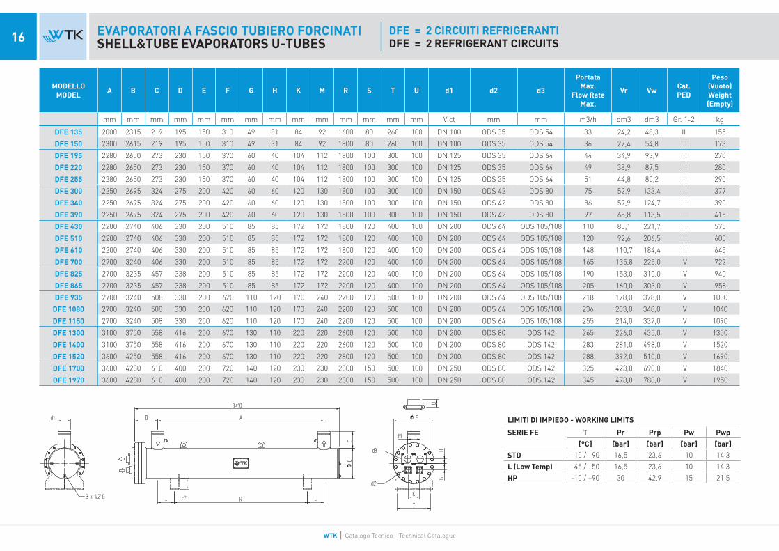
DFE = 2 CIRCUITI REFRIGERANTIDFE = 2 REFRIGERANT CIRCUITS
MODELLO MODEL A B C D E F G H K M R S T U d1 d2 d3
Portata Max.
Flow Rate Max.
Vr Vw Cat. PED
Peso (Vuoto) Weight (Empty)
mm mm mm mm mm mm mm mm mm mm mm mm mm mm Vict mm mm m3/h dm3 dm3 Gr. 1-2 kg
DFE 135 2000 2315 219 195 150 310 49 31 84 92 1600 80 260 100 DN 100 ODS 35 ODS 54 33 24,2 48,3 II 155
DFE 150 2300 2615 219 195 150 310 49 31 84 92 1800 80 260 100 DN 100 ODS 35 ODS 54 36 27,4 54,8 III 173
DFE 195 2280 2650 273 230 150 370 60 40 104 112 1800 100 300 100 DN 125 ODS 35 ODS 64 44 34,9 93,9 III 270
DFE 220 2280 2650 273 230 150 370 60 40 104 112 1800 100 300 100 DN 125 ODS 35 ODS 64 49 38,9 87,5 III 280
DFE 255 2280 2650 273 230 150 370 60 40 104 112 1800 100 300 100 DN 125 ODS 35 ODS 64 51 44,8 80,2 III 290
DFE 300 2250 2695 324 275 200 420 60 60 120 130 1800 100 300 100 DN 150 ODS 42 ODS 80 75 52,9 133,4 III 377
DFE 340 2250 2695 324 275 200 420 60 60 120 130 1800 100 300 100 DN 150 ODS 42 ODS 80 86 59,9 124,7 III 390
DFE 390 2250 2695 324 275 200 420 60 60 120 130 1800 100 300 100 DN 150 ODS 42 ODS 80 97 68,8 113,5 III 415
DFE 430 2200 2740 406 330 200 510 85 85 172 172 1800 120 400 100 DN 200 ODS 64 ODS 105/108 110 80,1 221,7 III 575
DFE 510 2200 2740 406 330 200 510 85 85 172 172 1800 120 400 100 DN 200 ODS 64 ODS 105/108 120 92,6 206,5 III 600
DFE 610 2200 2740 406 330 200 510 85 85 172 172 1800 120 400 100 DN 200 ODS 64 ODS 105/108 148 110,7 184,4 III 645
DFE 700 2700 3240 406 330 200 510 85 85 172 172 2200 120 400 100 DN 200 ODS 64 ODS 105/108 165 135,8 225,0 IV 722
DFE 825 2700 3235 457 338 200 510 85 85 172 172 2200 120 400 100 DN 200 ODS 64 ODS 105/108 190 153,0 310,0 IV 940
DFE 865 2700 3235 457 338 200 510 85 85 172 172 2200 120 400 100 DN 200 ODS 64 ODS 105/108 205 160,0 303,0 IV 958
DFE 935 2700 3240 508 330 200 620 110 120 170 240 2200 120 500 100 DN 200 ODS 64 ODS 105/108 218 178,0 378,0 IV 1000
DFE 1080 2700 3240 508 330 200 620 110 120 170 240 2200 120 500 100 DN 200 ODS 64 ODS 105/108 236 203,0 348,0 IV 1040
DFE 1150 2700 3240 508 330 200 620 110 120 170 240 2200 120 500 100 DN 200 ODS 64 ODS 105/108 255 214,0 337,0 IV 1090
DFE 1300 3100 3750 558 416 200 670 130 110 220 220 2600 120 500 100 DN 200 ODS 80 ODS 142 265 226,0 435,0 IV 1350
DFE 1400 3100 3750 558 416 200 670 130 110 220 220 2600 120 500 100 DN 200 ODS 80 ODS 142 283 281,0 498,0 IV 1520
DFE 1520 3600 4250 558 416 200 670 130 110 220 220 2800 120 500 100 DN 200 ODS 80 ODS 142 288 392,0 510,0 IV 1690
DFE 1700 3600 4280 610 400 200 720 140 120 230 230 2800 150 500 100 DN 250 ODS 80 ODS 142 325 423,0 690,0 IV 1840
DFE 1970 3600 4280 610 400 200 720 140 120 230 230 2800 150 500 100 DN 250 ODS 80 ODS 142 345 478,0 788,0 IV 1950
LIMITI DI IMPIEGO - WORKING LIMITS
SERIE FE T Pr Prp Pw Pwp
[°C] [bar] [bar] [bar] [bar]
STD -10 / +90 16,5 23,6 10 14,3
L (Low Temp) -45 / +50 16,5 23,6 10 14,3
HP -10 / +90 30 42,9 15 21,5
WTK Catalogo Tecnico - Technical Catalogue

EVAPORATORI A FASCIO TUBIERO FORCINATISHELL&TUBE EVAPORATORS U-TUBES
LIMITI DI IMPIEGO - WORKING LIMITS
SERIE FE T Pr Prp Pw Pwp
[°C] [bar] [bar] [bar] [bar]
STD -10 / +90 16,5 23,6 10 14,3
L (Low Temp) -45 / +50 16,5 23,6 10 14,3
HP -10 / +90 30 42,9 15 21,5
17EVAPORATORI A FASCIO TUBIERO FORCINATISHELL&TUBE EVAPORATORS U-TUBES
TFE = 3 CIRCUITI REFRIGERANTITFE = 3 REFRIGERANT CIRCUITS
MODELLO MODEL A B C D E F G H K I L M R S T U d1 d2 d3
Portata Max.
Flow Rate Max.
Vr Vw Cat. PED
Peso (Vuoto) Weight (Empty)
mm mm mm mm mm mm mm mm mm mm mm mm mm mm mm mm Vict mm mm m3/h dm3 dm3 Gr. 1-2 kg
TFE 430 2200 2740 406 330 200 510 70 70 120 110 110 120 1800 120 400 100 DN 200 ODS 42 ODS 80 110 80,1 221,7 III 575
TFE 510 2200 2740 406 330 200 510 70 70 120 110 110 120 1800 120 400 100 DN 200 ODS 42 ODS 80 120 92,6 206,5 III 600
TFE 610 2200 2740 406 330 200 510 70 70 120 110 110 120 1800 120 400 100 DN 200 ODS 42 ODS 80 148 110,7 184,4 III 645
TFE 700 2700 3240 406 330 200 510 70 70 120 110 110 120 2200 120 400 100 DN 200 ODS 42 ODS 80 165 135,8 225,0 III 722
TFE 825 2700 3260 457 352 200 510 70 70 120 110 110 120 2200 120 400 100 DN 200 ODS 42 ODS 80 190 153,0 310,0 III 940
TFE 865 2700 3260 457 352 200 510 70 70 120 110 110 120 2200 120 400 100 DN 200 ODS 42 ODS 80 205 160,0 303,0 III 958
TFE 935 2700 3240 508 330 200 620 95 95 140 95 155 160 2200 120 500 100 DN 200 ODS 42 ODS 105-108 218 178,0 378,0 III 1000
TFE 1080 2700 3240 508 330 200 620 95 95 140 95 155 160 2200 120 500 100 DN 200 ODS 42 ODS 105-108 236 203,0 348,0 IV 1040
TFE 1150 2700 3240 508 330 200 620 95 95 140 95 155 160 2200 120 500 100 DN 200 ODS 42 ODS 105-108 255 214,0 337,0 IV 1090
TFE 1300 3100 3750 558 416 285 670 110 80 165 160 160 165 2600 120 500 100 DN 200 ODS 54 ODS 105-108 265 226,0 435,0 IV 1350
TFE 1400 3100 3750 558 416 285 670 110 80 165 160 160 165 2600 120 500 100 DN 200 ODS 54 ODS 105-108 283 281,0 498,0 IV 1520
TFE 1520 3600 4250 558 416 285 670 110 80 165 160 160 165 2800 120 500 100 DN 200 ODS 54 ODS 105-108 288 392,0 510,0 IV 1690
TFE 1700 3600 4280 610 400 285 720 130 110 165 130 160 165 2800 120 500 100 DN 250 ODS 54 ODS 105-108 325 423,0 690,0 IV 1840
TFE 1970 3600 4280 610 400 285 720 130 110 165 130 160 165 2800 120 500 100 DN 250 ODS 54 ODS 105-108 345 478,0 788,0 IV 1950
WTK Catalogo Tecnico - Technical Catalogue

18 EVAPORATORI A FASCIO TUBIERO FORCINATISHELL&TUBE EVAPORATORS U-TUBES
QFE = 4 CIRCUITI REFRIGERANTIQFE = 4 REFRIGERANT CIRCUITS
MODELLO MODEL A B C D E F G H K I L M N O R S T U d1 d2 d3
Portata Max.
Flow Rate Max.
Vr Vw Cat. PED
Peso (Vuoto) Weight (Empty)
mm mm mm mm mm mm mm mm mm mm mm mm mm mm mm mm mm mm Vict mm mm m3/h dm3 dm3 Gr. 1-2 kg
QFE 430 2200 2740 406 330 200 510 70 50 39 100 100 47 140 140 2200 120 400 100 DN 200 ODS 35 ODS 64 110 80,1 221,7 III 575
QFE 510 2200 2740 406 330 200 510 70 50 39 100 100 47 140 140 2200 120 400 100 DN 200 ODS 35 ODS 64 120 92,6 206,5 III 600
QFE 610 2200 2740 406 330 200 510 70 50 39 100 100 47 140 140 2200 120 400 100 DN 200 ODS 35 ODS 64 148 110,7 184,4 III 645
QFE 700 2700 3240 406 330 200 510 70 50 39 100 100 47 140 140 2200 120 400 100 DN 200 ODS 35 ODS 64 165 135,8 225,0 III 722
QFE 825 2700 3260 457 352 200 510 70 50 39 100 100 47 140 140 2200 120 400 100 DN 200 ODS 35 ODS 64 190 153,0 310,0 III 940
QFE 865 2700 3260 457 352 200 510 70 50 39 100 100 47 140 140 2200 120 400 100 DN 200 ODS 35 ODS 64 205 160,0 303,0 III 958
QFE 935 2700 3280 508 358 200 620 110 85 59 85 110 59 177 177 2200 120 500 100 DN 200 ODS 42 ODS 42 218 178,0 378,0 III 1000
QFE 1080 2700 3280 508 358 200 620 110 85 59 85 110 59 177 177 2200 120 500 100 DN 200 ODS 42 ODS 42 236 203,0 348,0 III 1040
QFE 1150 2700 3280 508 358 200 620 110 85 59 85 110 59 177 177 2200 120 500 100 DN 200 ODS 42 ODS 42 255 214,0 337,0 III 1090
QFE 1300 3100 3790 558 418 285 670 115 75 66 115 186 200 66 200 2600 120 500 100 DN 200 ODS 64 ODS 105-108 265 226,0 435,0 III 1350
QFE 1400 3100 3790 558 418 285 670 115 75 66 115 186 200 66 200 2600 120 500 100 DN 200 ODS 64 ODS 105-108 283 281,0 498,0 IV 1520
QFE 1520 3600 4290 558 418 285 670 115 75 66 115 186 200 66 200 2800 120 500 100 DN 200 ODS 64 ODS 105-108 288 392,0 510,0 IV 1690
QFE 1700 3600 4336 610 438 285 720 130 70 70 130 155 210 70 210 2800 120 500 100 DN 250 ODS 64 ODS 105-108 325 423,0 690,0 IV 1840
QFE 1970 3600 4336 610 438 285 720 130 70 70 130 155 210 70 210 2800 120 500 100 DN 250 ODS 64 ODS 105-108 345 478,0 788,0 IV 1950
LIMITI DI IMPIEGO - WORKING LIMITS
SERIE FE T Pr Prp Pw Pwp
[°C] [bar] [bar] [bar] [bar]
STD -10 / +90 16,5 23,6 10 14,3
L (Low Temp) -45 / +50 16,5 23,6 10 14,3
HP -10 / +90 30 42,9 15 21,5

19EVAPORATORI CON ACCUMULO D’ACQUAEVAPORATORS WITH WATER TANKS
MODELLI TWI serbatoi d’accumulo acqua con evaporatore integrato rappresentano un’interessante soluzione per applicazioni dove necessita avere sempre dell’acqua raffreddata e pronta a disposizione. Abbinando un recipiente con la funzione di accumulo ad un evaporatore a fascio tubiero di tipo forcinato appositamente modificato, si può ottenere il risultato di cui sopra. L’accumulo può essere fatto sull’acqua in entrata o su quella in uscita.Ogni serbatoio è stato progettato per poter essere abbinato con evaporatori di diversa potenza, per cui a parità di capacità di accumulo si possono avere diverse potenze frigorifere. La gamma comprende modelli con capacità di accumulo da circa 190 litri a 3000 litri, abbinabili a potenze frigorifere da circa 20 kW a 1600 kW.Le opzioni disponibili sono staffe superiori per fissaggio di altri componenti e l’isolamento termico.Test, qualità, limiti d’impiego sono quelli degli evaporatori installati (attenzione: pressione di lavoro lato acqua = 6 bar).
MODELS TWThe buffer water tanks with integrated evaporator offer an interesting solution to the applications where it is necessary to have always available some cool water ready to use. Matching a tank with the function of water storage with a shell & tube evaporator “U-tube” type purpose modified for the scope, the above result can be achieved. The water storage is possible either on the entering or leaving water. Each tank has been designed to be matched with evaporators of different cooling capacities, so for the same water storage volume different cooling capacities are available. The range includes models with storage volume from about 190 litres to 3000 litres, that can work with evaporators whose duty goes from about 20 kW to 1600 kW.The options available are special welded supports on top of the tank for the fixing of other components and the thermal insulation.Test, quality, working limits are the ones of the installed evaporators (attention: design pressure water side = 6 bar).
MODELLO MODEL A B Ø D Ø C E F G H I L d1 - d2 STAFFE
SADDLES Vw
Peso (Vuoto) Weight (Empty)
ALLOWED MODELS MODELLI INSERIBILI
mm mm mm mm mm mm mm mm mm mm Thrd/Vict N° dm3 kg SCE - DCE - TCE - QCE SFE - DFE - TFE - QFE
TW 250 1470 1370 480 195/245 160 190 380 540 850 500 2” 2 250 55 23 33 43 53 63 73 - - - - - - - - - -
TW 480 1900 1740 600 245/270 200 240 480 660 1200 620 2.1/2” 2 475 84 63 73 83 103 133 - - - - - - - - - - -
TW 620 2385 2270 600 270/310 200 240 480 660 1500 620 3” 2 618 195 133 143 163 203 - - - - 135 - - - - - - -
TW 1100 2715 2580 750 310/370/420 280 300 600 770 1000 780 DN 100 3 1095 324 203 243 293 343 393 453 513 583 135 150 195 220 255 300 340 390
TW 1400 3300 3150 750 370/420 220 300 600 770 1200 780 DN 125 3 1350 530 293 343 393 453 513 583 - - 195 220 255 300 340 390 - -
TW 2000 2830 2650 1000 420 370 380 800 1030 1000 1030 DN 150 3 1990 700 453 513 583 - - - - - 300 340 390 - - - - -
TW 2500 3520 3300 1000 510 370 380 800 1030 1200 1030 DN 200 3 2500 700 673 783 923 1053 1133 1223 - - 430 510 610 700 825 865 - -
TW 3000 4170 3900 1000 620/670 370 380 800 1030 1000 1030 DN 200 4 2980 1300 1373 1533 1583 - - - - - 935 1080 1150 1300 1400 1520 - -
SERIE TWSERIES TW

20 EVAPORATORI A FASCIO TUBIERO TIPO “TUBO DRITTO”SHELL & TUBE EVAPORATORS TYPE “STRAIGHT TUBE”
WTK Catalogo Tecnico - Technical Catalogue

EVAPORATORI A FASCIO TUBIERO TIPO “TUBO DRITTO”SHELL & TUBE EVAPORATORS TYPE “STRAIGHT TUBE” 21EVAPORATORI A FASCIO TUBIERO TIPO “TUBO DRITTO”
SHELL & TUBE EVAPORATORS TYPE “STRAIGHT TUBE”
MATERIALI IMPIEGATIL’utilizzo dei materiali impiegati negli evaporatori è subordinato ai rigidi controlli qualitativi effettuati in base alla normativa PED (Dir. 2014/68/UE) ed alle Norme Europee che regolano e sovraintendono alla costruzione dei recipienti a pressione.I componenti standard sono:- acciaio al carbonio: testata, piastra tubiera, mantello e connessioni frigorifere ed idrauliche,- rame lega C12200 – EN12452/SB359 con rigatura interna elicoidale adatta per tubi scambiatori, - guarnizioni esenti amianto idonee all’impiego per refrigeranti HCFC, HFC, HFO,- setti in plastica PVC,- viti di fissaggio conformi alle temperature di utilizzo in acciaio legato.
TEST E QUALITA’I controlli vengono effettuati in base al manuale interno di qualità UNI EN ISO 9001 e specificatamente tutti gli evaporatori vengono sottoposti a:- prova pressione lato refrigerante e lato acqua (coefficiente x 1,43),- prova di pressione differenziata di ogni singolo circuito refrigerante,- prova di tenuta con cercafughe a elio (valore max. accettato comparabile a 3 g/anno di R22).Al termine del test, i circuiti refrigeranti vengono asciugati e protetti con degli assorbitori di umidità prima di essere spediti ai clienti.
MODELLI (espansione secca) SPE – DPE – TPEGli evaporatori della serie _PE sono definiti “monopasso” od in perfetto controcorrente con ingombri di spazio ridotti rispetto agli evaporatori tradizionali (tubi forcinati). Ottimizzati per applicazioni con gas re-frigerante R134a e HFO, garantiscono altissime performance della macchina frigorifera grazie ad approc-ci tra la temperatura di evaporazione e l’uscita del fluido freddo dimezzati rispetto a quanto è possibile ottenere con scambiatori con tubo forcinato. Le cariche di refrigerante a parità di performance e potenza sono assai ridotte grazie all’efficienza di scambio termico garantita.Questi modelli hanno la possibilità di variare la posizione degli attacchi acqua (verticali, destri o sinistri). La costruzione dei setti permette di ridurre al minimo eventuali by-pass di fluido: inoltre possono essere realizzati con distanza setti differenti per mantenere un’alta efficienza anche con basse portate, in modo particolare, con le miscele anticongelanti. Le opzioni disponibili sono staffe saldate, connessioni lato acqua flangiate, isolamento termico, resisten-ze elettriche adesive.
MODELLI (allagati) FME – FWEGli evaporatori allagati garantiscono efficienza energetica e performance di scambio termico in evapora-zione mai raggiunte, assecondano in questo modo le esigenze del mercato attuale e di tutti i costruttori di macchine frigorifere. L’evaporatore allagato è stato studiato principalmente per il condizionamento con fluidi frigorigeni non azeotropi; grazie alla ricerca e sviluppo di speciali tubi alettati, nascono nume-rosi modelli che coprono un’ampia gamma di potenze in grado di assecondare ogni richiesta dato che è possibile ottenere approcci ridottissimi, fino a 1-1,5 K tra temperatura di evaporazione ed uscita fluido da raffreddare. In questo modo si garantiscono i più alti livelli di C.O.P. ed efficienza energetica in ogni condi-zione di lavoro. I nostri evaporatori allagati sono idonei ad applicazioni con qualsiasi tipo di compressore sia oil free che a vite e nell’eventualità di compressori con olii particolarmente viscosi non miscibili al refrigerante consigliamo l’installazione dei nostri separatori d’olio secondari tipo RS.Tutti gli evaporatori della serie FME possono essere realizzati con una lunghezza variabile a seconda delle specifiche esigenze applicative. Il rapporto tra le dimensioni di ingombro e condizioni di lavoro risulta quindi sempre ottimale.Tutti gli evaporatori della serie FWE invece hanno lunghezze modulari predeterminate ma impiegano un tubo scambiatore ad alta efficienza di ultima generazione, garantendo il massimo della resa.Le opzioni disponibili sono staffe saldate, isolamento termico, spia di liquido.
MATERIALSThe choice of the materials used in the evaporators is the result of strict quality checks carried out in compliance with the PED norm (Dir. 2014/68/UE) and the European norms regulating the construction of pressure vessels.The standard components are:- carbon steel: head, tube sheet, shell and refrigerant and water connections,- copper alloy C12200 – EN12452/SB359 with inner finned surface suitable for exchanger pipes, - asbestos free gaskets suitable for the use of HCFC, HFC, HFO refrigerants,- PVC plastic baffles,- bonded steel bolts fit for the temperatures generated during the use.
TEST AND QUALITYAll tests comply with the procedures of our internal quality manual UNI EN ISO 9001 and specifically all the evaporators undergo the following:- pressure test refrigerant and water side (coefficient x 1,43),- separate pressure test for each single refrigerant circuit,- hydrostatic test with the use of a helium leakage detector (accepted max. level of 3 g/year of R22).Once the tests are over and before shipping, the refrigerant circuits are dried and protected against hu-midity by means of moisture absorber bags.
MODELS (dry-expansion) SPE – DPE – TPEThe evaporators of the series _PE are named “single pass” or in perfect counter-current with reduced footprint against the traditional evaporators “U” tubes. They are purpose designed for applications with refrigerant R134a and HFO and can grant very high performance of the chiller thanks to half-reduced approach between the evaporation temperature and the outlet of the cold fluid with respect to what is obtainable with heat exchangers made with “U” tubes. The refrigerant volumes at same performance and cooling capacity are rather lower due to the good efficiency of the heat exchange. There is the possibi-lity to change the position of the water connections (vertical, right or left). The baffles are positioned to enable a nominal velocity of the fluid compatible with the pressure drop which may occur and to reduce to the least possible any by-pass of fluid. Besides such models can be assembled with different distance between the baffles in order to grant high efficiency even when the flow rate is low, particularly with anti-freezing solutions. The options available are welded feet, water connections flanged type, thermal insulation, adhesive electric heaters.
MODELS (flooded) FME – FWEThe flooded evaporators offer energy efficiency and heat exchange performance never achieved with other models, following in this way the market current needs and the ones of all the manufacturers of chillers. The flooded evaporator has been designed mainly for air conditioning using non-azeotropic refrigerants; thanks to some research and development of special finned tubes, our various models can cover a wide range of cooling duties with minimum temperature approaches, even 1-1,5 K between the evaporation temperature and the fluid outlet to be cooled down. Thus these models can give the highest levels of C.O.P. and energy efficiency at each operating condition. Our flooded evaporators can be instal-led with any type of compressor, both oil free and screw type; in case of compressors using oils rather viscous not mixable with the refrigerant we can advise to install our secondary oil separators model RS. All the evaporators series FME can be manufactured with variable lengths upon specific applications. The relation between the footprint and the working conditions results in this way always the best possible achievement. All the evaporators series FWE instead, have modular fixed lengths but are made with the last generation of high efficiency exchanger tubes, granting therefore the utmost performance.The options available are welded feet, thermal insulation, sight glass.
WTK Catalogo Tecnico - Technical Catalogue

22 EVAPORATORI A FASCIO TUBIERO - SERIE PESHELL&TUBE EVAPORATORS - PE SERIES
SPE = 1 CIRCUITO REFRIGERANTESPE = 1 REFRIGERANT CIRCUIT
* FORNITO CON COLLETTORE A “T” PER INGRESSO FLUIDO* SUPPLIED WITH “T” COLLECTOR FOR FLUID INLET
MODELLO MODEL A B C D E F K P R S T U d1 d2 d3 d4 d5
Portata Max.
Flow Rate Max.
Vr Vw Cat. PED
Peso (Vuoto) Weight (Empty)
mm mm mm mm mm mm mm mm mm mm mm mm Vict mm mm inch inch m3/h dm3 dm3 Gr. 1 kg
SPE 210 2400 2900 273 175 150 340 72 2750 1800 48 220 100 DN125 ODS42 * ODS80 1/4” 1/2” 49,6 19 77 III 256
SPE 230 2400 2900 273 175 150 340 72 2750 1800 48 220 100 DN125 ODS42 * ODS80 1/4” 1/2” 49,6 33 115 III 259,5
SPE 260 2400 2900 273 175 150 340 72 2750 1800 48 220 100 DN125 ODS42 * ODS80 1/4” 1/2” 56,1 38 109 III 266,6
SPE 300 2400 2900 273 175 150 340 72 2750 1800 48 220 100 DN125 ODS42 * ODS80 1/4” 1/2” 64,8 42 106 III 271,2
SPE 350 2400 2900 273 175 150 340 72 2750 1800 48 220 100 DN125 ODS42 * ODS80 1/4” 1/2” 75,6 44 103 III 274,3
SPE 370 2400 2920 324 175 200 390 104 2750 1800 58 220 100 DN150 ODS42 * ODS105/108 1/4” 1/2” 79,9 52 159 III 290,1
SPE 440 2400 2920 324 175 200 390 104 2750 1800 58 232 100 DN150 ODS42 * ODS105/108 1/4” 1/2” 95 58 153 III 296,8
SPE 490 2400 2920 324 175 200 390 104 2750 1800 58 232 100 DN150 ODS42 * ODS105/108 1/4” 1/2” 105,8 62 148 IV 302,5
SPE 560 2350 2945 406 200 200 480 131 2750 1800 55 320 100 DN200 ODS42 * ODS105/108 1/4” 1/2” 120,9 73 261 IV 470
SPE 630 2350 2945 406 200 200 480 131 2750 1800 55 320 100 DN200 ODS42 * ODS105/108 1/4” 1/2” 136 79 255 IV 476,2
SPE 700 2350 2945 406 200 200 480 131 2750 1800 55 320 100 DN200 ODS42 * ODS105/108 1/4” 1/2” 151,1 87 247 IV 485,3
SPE 800 2350 2945 406 200 200 480 131 2750 1800 55 320 100 DN200 ODS42 * ODS105/108 1/4” 1/2” 172,7 95 240 IV 492,9
SPE 860 2350 2945 406 200 200 480 131 2750 1800 55 400 100 DN200 ODS42 * ODS105/108 1/4” 1/2” 185,6 100 235 IV 499,7
LIMITI DI IMPIEGO - WORKING LIMITS
SERIE PE T Pr Prp Pw Pwp
[°C] [bar] [bar] [bar] [bar]
STD -10 / +90 16,5 23,6 10 14,3
L (Low Temp) -45 / +50 22 31,46 10 14,3
WTK Catalogo Tecnico - Technical Catalogue

LIMITI DI IMPIEGO - WORKING LIMITS
SERIE PE T Pr Prp Pw Pwp
[°C] [bar] [bar] [bar] [bar]
STD -10 / +90 16,5 23,6 10 14,3
L (Low Temp) -45 / +50 22 31,46 10 14,3
23EVAPORATORI A FASCIO TUBIERO - SERIE PESHELL&TUBE EVAPORATORS - PE SERIES
DPE = 2 CIRCUITI REFRIGERANTEDPE = 2 REFRIGERANT CIRCUITS
MODELLO MODEL A B C D E F K M P R S T U d1 d2 d3 d4 d5
Portata Max.
Flow Rate Max.
Vr Vw Cat. PED
Peso (Vuoto) Weight (Empty)
mm mm mm mm mm mm mm mm mm mm mm mm mm Vict mm mm inch inch m3/h dm3 dm3 Gr. 1-2 kg
DPE 210 2400 2900 273 175 150 340 72 122 2750 1800 48 220 100 DN 125 ODS 35 ODS 64 1/4” 1/2” 49,6 35 111,7 III 257,4DPE 230 2400 2900 273 175 150 340 72 122 2750 1800 48 220 100 DN 125 ODS 35 ODS 64 1/4” 1/2” 49,6 38,5 107,7 III 260,9DPE 260 2400 2900 273 175 150 340 72 102 2750 1800 48 220 100 DN 125 ODS 35 ODS 64 1/4” 1/2” 56,1 43,9 101,6 III 268DPE 300 2400 2900 273 175 150 340 72 102 2750 1800 48 220 100 DN 125 ODS 35 ODS 64 1/4” 1/2” 64,8 47,9 97 III 272,6DPE 350 2400 2900 273 175 150 340 72 102 2750 1800 48 220 100 DN 125 ODS 35 ODS 64 1/4” 1/2” 75,6 50,2 94,3 III 275,7DPE 370 2400 2920 324 175 200 390 104 122 2750 1800 58 232 100 DN 150 ODS 42 ODS 80 1/4” 1/2” 79,9 59,3 147 III 291,7DPE 440 2400 2920 324 175 200 390 104 122 2750 1800 58 232 100 DN 150 ODS 42 ODS 80 1/4” 1/2” 95 65,4 140,1 III 298,4DPE 490 2400 2920 324 175 200 390 104 122 2750 1800 58 232 100 DN 150 ODS 42 ODS 80 1/4” 1/2” 105,8 70,1 134,8 III 304,1DPE 560 2350 2945 406 200 200 480 131 150 2750 1800 55 320 100 DN 200 ODS 54 ODS 105/108 1/4” 1/2” 120,9 84,5 244,1 III 471,2DPE 630 2350 2945 406 200 200 480 131 150 2750 1800 55 320 100 DN 200 ODS 54 ODS 105/108 1/4” 1/2” 136 90,6 237,2 III 477,4DPE 700 2350 2945 406 200 200 480 131 150 2750 1800 55 320 100 DN 200 ODS 54 ODS 105/108 1/4” 1/2” 151,1 98,9 227,9 III 486,5DPE 800 2350 2945 406 200 200 480 131 150 2750 1800 55 320 100 DN 200 ODS 54 ODS 105/108 1/4” 1/2” 172,7 105,9 219,9 III 494,1DPE 860 2350 2945 406 200 200 480 131 150 2750 1800 55 320 100 DN 200 ODS 54 ODS 105/108 1/4” 1/2” 185,6 111,8 213,2 III 500,9DPE 930 2350 2950 508 200 200 580 150 188 2750 1800 55 410 100 DN 200 ODS 64/67 ODS 105/108 1/4” 1/2” 201 135,3 381,8 IV 674,6
DPE 1000 2350 2950 508 200 200 580 150 188 2750 1800 55 410 100 DN 200 ODS 64/67 ODS 105/108 1/4” 1/2” 216 114,6 374,7 IV 681,2DPE 1100 2350 2950 508 200 200 580 150 188 2750 1800 55 410 100 DN 200 ODS 64/67 ODS 105/108 1/4” 1/2” 237 105,1 365,2 IV 689,9DPE 1200 2350 2950 508 200 200 580 150 188 2750 1800 55 410 100 DN 200 ODS 64/67 ODS 105/108 1/4” 1/2” 259 161,8 352 IV 703DPE 1300 3200 3800 508 200 200 580 150 188 3600 2500 55 410 100 DN 200 ODS 64/67 ODS 105/108 1/4” 1/2” 278 171,5 503,7 IV 795,8DPE 1400 3200 3800 508 200 200 580 150 188 3600 2500 55 410 100 DN 200 ODS 64/67 ODS 105/108 1/4” 1/2” 298 179,8 494,3 IV 802,4DPE 1500 3200 3800 508 200 200 580 150 188 3600 2500 55 410 100 DN 200 ODS 64/67 ODS 105/108 1/4” 1/2” 322 190,9 481,8 IV 815,2DPE 1600 3200 3800 508 200 200 580 150 188 3600 2500 55 410 100 DN 200 ODS 64/67 ODS 105/108 1/4” 1/2” 348 206,3 464,4 IV 839,9DPE 1760 3150 3790 610 225 200 680 200 200 3600 2500 55 482 100 DN 250 ODS 80 ODS 105/108 1/4” 1/2” 380 214,4 753,7 IV 1276,5DPE 1960 3150 3790 610 225 200 680 200 200 3600 2500 55 482 100 DN 250 ODS 80 ODS 105/108 1/4” 1/2” 423 227,3 721,1 IV 1291,3DPE 2110 3150 3790 610 225 200 680 200 200 3600 2500 55 482 100 DN 250 ODS 80 ODS 105/108 1/4” 1/2” 455 242,1 704,4 IV 1313,4DPE 2290 3150 3790 610 225 200 680 200 200 3600 2500 55 482 100 DN 250 ODS 80 ODS 105/108 1/4” 1/2” 494 255 689,8 IV 1343,9
WTK Catalogo Tecnico - Technical Catalogue

24 EVAPORATORI A FASCIO TUBIERO - SERIE PESHELL&TUBE EVAPORATORS - PE SERIES
TPE = 3 CIRCUITI REFRIGERANTETPE = 3 REFRIGERANT CIRCUITS
LIMITI DI IMPIEGO - WORKING LIMITS
SERIE PE T Pr Prp Pw Pwp
[°C] [bar] [bar] [bar] [bar]
STD -10 / +90 16,5 23,6 10 14,3
L (Low Temp) -45 / +50 22 31,46 10 14,3
MODELLO MODEL A B C D E F K M P R S T U d1 d2 d3 d4 d5
Portata Max.
Flow Rate Max.
Vr Vw Cat. PED
Peso (Vuoto) Weight (Empty)
mm mm mm mm mm mm mm mm mm mm mm mm mm Vict mm mm inch inch m3/h dm3 dm3 Gr. 1-2 kg
TPE 560 2350 2945 406 200 200 480 95 112 2750 1800 55 320 100 DN 200 ODS 54 ODS 80 1/4” 1/2” 120,9 84,5 244,1 III 580,9
TPE 630 2350 2945 406 200 200 480 95 112 2750 1800 55 320 100 DN 200 ODS 54 ODS 80 1/4” 1/2” 136 90,6 237,2 III 587,1
TPE 700 2350 2945 406 200 200 480 95 112 2750 1800 55 320 100 DN 200 ODS 54 ODS 80 1/4” 1/2” 151,1 98,9 227,9 III 596,2
TPE 800 2350 2945 406 200 200 480 95 112 2750 1800 55 320 100 DN 200 ODS 54 ODS 80 1/4” 1/2” 172,7 105,9 219,9 III 603,8
TPE 860 2350 2945 406 200 200 480 95 112 2750 1800 55 320 100 DN 200 ODS 54 ODS 80 1/4” 1/2” 185,6 111,8 213,2 III 610,6
TPE 930 2350 2950 508 200 200 580 132 132 2750 1800 55 410 100 DN 200 ODS 54 ODS 89 1/4” 1/2” 201 135,3 381,8 III 834,6
TPE 1000 2350 2950 508 200 200 580 132 132 2750 1800 55 410 100 DN 200 ODS 54 ODS 89 1/4” 1/2” 216 114,6 374,7 III 841,2
TPE 1100 2350 2950 508 200 200 580 132 132 2750 1800 55 410 100 DN 200 ODS 54 ODS 89 1/4” 1/2” 237 105,1 365,2 III 849,9
TPE 1200 2350 2950 508 200 200 580 132 132 2750 1800 55 410 100 DN 200 ODS 54 ODS 89 1/4” 1/2” 259 161,8 352 III 863
TPE 1300 3200 3800 508 200 200 580 132 132 3600 2500 55 410 100 DN 200 ODS 54 ODS 89 1/4” 1/2” 278 171,5 503,7 III 955,8
TPE 1400 3200 3800 508 200 200 580 132 132 3600 2500 55 410 100 DN 200 ODS 54 ODS 89 1/4” 1/2” 298 179,8 494,3 III 962,4
TPE 1500 3200 3800 508 200 200 580 132 132 3600 2500 55 410 100 DN 200 ODS 54 ODS 89 1/4” 1/2” 322 190,9 481,8 IV 975,2
TPE 1600 3200 3800 508 200 200 580 132 132 3600 2500 55 410 100 DN 200 ODS 54 ODS 89 1/4” 1/2” 348 206,3 464,4 IV 999,9
TPE 1760 3150 3790 610 225 200 680 175 175 3600 2500 55 482 100 DN 250 ODS 64 ODS 105/108 1/4” 1/2” 380 214,4 753,7 IV 1277,5
TPE 1960 3150 3790 610 225 200 680 175 175 3600 2500 55 482 100 DN 250 ODS 64 ODS 105/108 1/4” 1/2” 423 227,3 721,1 IV 1292,3
TPE 2110 3150 3790 610 225 200 680 175 175 3600 2500 55 482 100 DN 250 ODS 64 ODS 105/108 1/4” 1/2” 455 242,1 704,4 IV 1314,4
TPE 2290 3150 3790 610 225 200 680 175 175 3600 2500 55 482 100 DN 250 ODS 64 ODS 105/108 1/4” 1/2” 494 255 689,8 IV 1344,9
WTK Catalogo Tecnico - Technical Catalogue

25EVAPORATORI ALLAGATI A FASCIO TUBIEROFLOODED EVAPORATORS
MATERIALI IMPIEGATIL’utilizzo dei materiali impiegati negli evaporatori è subordinato ai rigidi controlli qualitativi effettuati in base alla normativa PED (Dir. 2014/68/UE) ed alle Norme Europee che regolano e sovraintendono alla costruzione dei recipienti a pressione.I componenti standard sono:- acciaio al carbonio: testata, piastra tubiera, mantello e connessioni frigorifere ed idrauliche,- rame lega C12200 – EN12452/SB359 con rigatura interna elicoidale adatta per tubi scambiatori, - guarnizioni esenti amianto idonee all’impiego per refrigeranti HCFC, HFC, HFO,- setti in plastica PVC,- viti di fissaggio conformi alle temperature di utilizzo in acciaio legato.
TEST E QUALITA’I controlli vengono effettuati in base al manuale interno di qualità UNI EN ISO 9001 e specificatamente tutti gli evaporatori vengono sottoposti a:- prova pressione lato refrigerante e lato acqua (coefficiente x 1,43),- prova di pressione differenziata di ogni singolo circuito refrigerante,- prova di tenuta con cercafughe a elio (valore max. accettato comparabile a 3 g/anno di R22).Al termine del test, i circuiti refrigeranti vengono asciugati e protetti con degli assorbitori di umidità prima di essere spediti ai clienti.
MODELLI (allagati) FME – FWEGli evaporatori allagati garantiscono efficienza energetica e performance di scambio termico in evapora-zione mai raggiunte, assecondano in questo modo le esigenze del mercato attuale e di tutti i costruttori di macchine frigorifere. L’evaporatore allagato è stato studiato principalmente per il condizionamento con fluidi frigorigeni non azeotropi; grazie alla ricerca e sviluppo di speciali tubi alettati, nascono nume-rosi modelli che coprono un’ampia gamma di potenze in grado di assecondare ogni richiesta dato che è possibile ottenere approcci ridottissimi, fino a 1-1,5 K tra temperatura di evaporazione ed uscita fluido da raffreddare. In questo modo si garantiscono i più alti livelli di C.O.P. ed efficienza energetica in ogni condi-zione di lavoro. I nostri evaporatori allagati sono idonei ad applicazioni con qualsiasi tipo di compressore sia oil free che a vite e nell’eventualità di compressori con olii particolarmente viscosi non miscibili al refrigerante consigliamo l’installazione dei nostri separatori d’olio secondari tipo RS.Tutti gli evaporatori della serie FME possono essere realizzati con una lunghezza variabile a seconda delle specifiche esigenze applicative. Il rapporto tra le dimensioni di ingombro e condizioni di lavoro risulta quindi sempre ottimale.Tutti gli evaporatori della serie FWE invece hanno lunghezze modulari predeterminate ma impiegano un tubo scambiatore ad alta efficienza di ultima generazione, garantendo il massimo della resa.Le opzioni disponibili sono staffe saldate, isolamento termico, spia di liquido.
MATERIALSThe choice of the materials used in the evaporators is the result of strict quality checks carried out in compliance with the PED norm (Dir. 2014/68/UE) and the European norms regulating the construction of pressure vessels.The standard components are:- carbon steel: head, tube sheet, shell and refrigerant and water connections,- copper alloy C12200 – EN12452/SB359 with inner finned surface suitable for exchanger pipes, - asbestos free gaskets suitable for the use of HCFC, HFC, HFO refrigerants,- PVC plastic baffles,- bonded steel bolts fit for the temperatures generated during the use.
TEST AND QUALITYAll tests comply with the procedures of our internal quality manual UNI EN ISO 9001 and specifically all the evaporators undergo the following:- pressure test refrigerant and water side (coefficient x 1,43),- separate pressure test for each single refrigerant circuit,- hydrostatic test with the use of a helium leakage detector (accepted max. level of 3 g/year of R22).Once the tests are over and before shipping, the refrigerant circuits are dried and protected against hu-midity by means of moisture absorber bags.
MODELS (flooded) FME – FWEThe flooded evaporators offer energy efficiency and heat exchange performance never achieved with other models, following in this way the market current needs and the ones of all the manufacturers of chillers. The flooded evaporator has been designed mainly for air conditioning using non-azeotropic refrigerants; thanks to some research and development of special finned tubes, our various models can cover a wide range of cooling duties with minimum temperature approaches, even 1-1,5 K between the evaporation temperature and the fluid outlet to be cooled down. Thus these models can give the highest levels of C.O.P. and energy efficiency at each operating condition. Our flooded evaporators can be instal-led with any type of compressor, both oil free and screw type; in case of compressors using oils rather viscous not mixable with the refrigerant we can advise to install our secondary oil separators model RS. All the evaporators series FME can be manufactured with variable lengths upon specific applications. The relation between the footprint and the working conditions results in this way always the best possible achievement. All the evaporators series FWE instead, have modular fixed lengths but are made with the last generation of high efficiency exchanger tubes, granting therefore the utmost performance.The options available are welded feet, thermal insulation, sight glass.
WTK Catalogo Tecnico - Technical Catalogue

26 EVAPORATORI ALLAGATI A FASCIO TUBIERO - SERIE FMEFLOODED EVAPORATORS - FME SERIES
LIMITI DI IMPIEGO - WORKING LIMITS
SERIE FME T Pr Prp Pw Pwp
[°C] [bar] [bar] [bar] [bar]
STD -10 / +90 16,5 23,6 10 14,3
MODELLO MODEL A B C D E F H N M P d1 d2 d3 d4 d5
Portata Max.
Flow Rate Max.
Vr Vr cal Vw Cat. PED
Peso (Vuoto) Weight (Empty)
mm mm mm mm mm mm mm mm mm mm Thrd/Vict Thrd/Vict mm mm mm m3/h dm3 dm3 dm3 Gr. 1 kg
FME 110 1940 1750 324 350 520 0 230 30 30 1800 2.1/2” 2” ODS 35 ODS 64/67 - OD 76 ODS 22 18 114,0 48,1 19,7 IV 181
FME 140 1940 1750 324 350 520 0 230 30 30 1800 2.1/2” 2” ODS 35 ODS 64/67 - OD 76 ODS 22 24 108,1 43,1 24,5 IV 193
FME 180 1940 1750 324 350 520 0 230 30 30 1800 2.1/2” 2” ODS 35 ODS 64/67 - OD 76 ODS 22 31 100,1 36,2 30,8 IV 211
FME 225 1940 1750 406 440 610 10 290 30 30 1800 3” 2.1/2” ODS 42 ODS 80 - OD 89 ODS 22 38 173,4 80,8 39,4 IV 323
FME 270 1940 1750 406 440 610 10 290 30 30 1800 3” 2.1/2” ODS 42 ODS 80 - OD 89 ODS 22 46 165,5 74,8 45,8 IV 339
FME 320 1940 1750 406 440 610 10 290 30 30 1800 3” 2.1/2” ODS 42 ODS 80 - OD 89 ODS 22 55 155,6 64,9 53,8 IV 358
FME 385 1960 1740 457 500 660 30 380 30 30 1800 DN 100 DN 80 ODS 42 ODS 105/108 - OD 114 ODS 22 66 199,1 93,5 68,7 IV 475
FME 440 1960 1740 457 500 660 30 380 30 30 1800 DN 100 DN 80 ODS 42 ODS 105/108 - OD 114 ODS 22 75 189,2 88,6 76,6 IV 495
FME 535 2030 1740 558 620 770 30 480 40 40 1800 DN 125 DN 100 ODS 54 OD 141 ODS 22 91 298,6 136,9 108,0 IV 712
FME 640 2030 1740 558 620 770 30 480 40 40 1800 DN 125 DN 100 ODS 54 OD 141 ODS 22 110 278,9 119,1 124,0 IV 752
FME 750 2030 1740 610 670 820 50 510 40 40 1800 DN 125 DN 100 ODS 64/67 2 x OD 114 ODS 22 128 346,7 162,7 139,9 IV 916
FME 830 2030 1740 610 670 820 50 510 40 40 1800 DN 125 DN 100 ODS 64/67 2 x OD 114 ODS 22 142 330,9 146,9 152,7 IV 946
FME 930 2030 1740 710 770 920 70 590 40 40 1800 DN 150 DN 125 ODS 80 2 x OD 141 ODS 22 159 483,2 245,1 185,2 IV 1144
FME 1040 2030 1740 710 770 920 70 590 40 40 1800 DN 150 DN 125 ODS 80 2 x OD 141 ODS 22 177 463,4 227,4 201,1 IV 1183
FME 1100 2030 1740 710 770 920 70 590 40 40 1800 DN 150 DN 125 ODS 80 2 x OD 141 ODS 22 186 449,6 215,5 212,3 IV 1201
WTK Catalogo Tecnico - Technical Catalogue

LIMITI DI IMPIEGO - WORKING LIMITS
SERIE FWE T Pr Prp Pw Pwp
[°C] [bar] [bar] [bar] [bar]
STD -10 / +90 16,5 23,6 10 14,3
27EVAPORATORI ALLAGATI A FASCIO TUBIERO - SERIE FWEFLOODED EVAPORATORS - FWE SERIES
MODELLO MODEL A B C D E F H N M P d1 d2 d3 d4 d5
Portata Max.
Flow Rate Max.
Vr Vr cal Vw Cat. PED
Peso (Vuoto) Weight (Empty)
mm mm mm mm mm mm mm mm mm mm Thrd/Vict Thrd/Vict mm mm mm m3/h dm3 dm3 dm3 Gr. 1-2 kg
FWE 170 1940 1750 324 350 520 0 230 30 30 1800 2.1/2” 2” ODS 54 ODS 80 - OD 89 ODS 22 38 166,2 73,0 26,8 IV 221
FWE 220 1940 1750 324 350 520 0 230 30 30 1800 2.1/2” 2” ODS 54 ODS 80 - OD 89 ODS 22 50 157,5 62,8 33,7 IV 232
FWE 285 1940 1750 324 350 520 0 230 30 30 1800 2.1/2” 2” ODS 54 ODS 80 - OD 89 ODS 22 61 148,8 52,7 40,6 IV 250
FWE 350 1940 1750 406 440 610 10 290 30 30 1800 DN 100 3” ODS 54 ODS 105/108 - OD 114 ODS 22 77 255,6 122,0 52,0 IV 375
FWE 420 1940 1750 406 440 610 10 290 30 30 1800 DN 100 3” ODS 54 ODS 105/108 - OD 114 ODS 22 88 246,9 116,2 59,0 IV 391
FWE 500 1940 1750 406 440 610 10 290 30 30 1800 DN 100 3” ODS 54 ODS 105/108 - OD 114 ODS 22 107 232,4 104,7 70,5 IV 410
FWE 600 1960 1740 457 500 660 30 380 30 30 1800 DN 125 DN 100 ODS 64 2 x ODS 105/108 - OD 114 ODS 22 126 299,1 138,7 87,3 IV 592
FWE 690 1960 1740 457 500 660 30 380 30 30 1800 DN 125 DN 100 ODS 64 2 x ODS 105/108 - OD 114 ODS 22 145 284,7 127,1 98,8 IV 616
FWE 840 2030 1740 558 620 770 30 480 40 40 1800 DN 150 DN 125 2 x ODS 54 2 x ODS 105/108 - OD 114 ODS 22 176 447,3 202,7 134,3 IV 824
FWE 1000 2030 1740 558 620 770 30 480 40 40 1800 DN 150 DN 125 2 x ODS 54 2 x ODS 105/108 - OD 114 ODS 22 214 418,5 178,2 157,3 IV 863
FWE 1170 2030 1740 610 670 820 50 510 40 40 1800 DN 150 DN 125 2 x ODS 64 3 x ODS 105/108 - OD 114 ODS 22 249 520,4 244,6 178,1 IV 1122
FWE 1310 2030 1740 610 670 820 50 510 40 40 1800 DN 150 DN 125 2 x ODS 64 3 x ODS 105/108 - OD 114 ODS 22 287 491,5 218,7 201,1 IV 1153
FWE 1460 2030 1740 710 770 920 70 590 40 40 1800 DN 200 DN 150 2 x ODS 80 3 x OD 141 ODS 22 318 468,5 195,6 219,6 IV 1478
FWE 1620 2030 1740 710 770 920 70 590 40 40 1800 DN 200 DN 150 2 x ODS 80 3 x OD 141 ODS 22 356 439,6 169,7 242,6 IV 1517
FWE 1740 2030 1740 710 770 920 70 590 40 40 1800 DN 200 DN 150 2 x ODS 80 3 x OD 141 ODS 22 379 422,3 155,2 256,4 IV 1531
FWE 1850 2030 1740 710 770 920 70 590 40 40 1800 DN 200 DN 150 2 x ODS 80 3 x OD 141 ODS 22 398 407,9 143,7 268,0 IV 1544
WTK Catalogo Tecnico - Technical Catalogue

28 CONDENSATORI A FASCIO TUBIERO PER ACQUA DOLCE E MARINASHELL & TUBE CONDENSERS FOR FRESH AND SEA WATER
WTK Catalogo Tecnico - Technical Catalogue

29CONDENSATORI A FASCIO TUBIERO PER ACQUA DOLCE E MARINASHELL & TUBE CONDENSERS FOR FRESH AND SEA WATER
MATERIALI IMPIEGATIL’utilizzo dei materiali impiegati nei condensatori è subordinato ai rigidi controlli qualitativi effettuati in base alla normativa PED (Dir. 2014/68/UE) ed alle Norme Europee che regolano e sovraintendono alla costruzione dei recipienti a pressione.
I componenti standard sono:- acciaio al carbonio: chiusure, piastre tubiere, setto, mantello (sabbiato) e connessioni frigorifere ed idrauliche,- lega di rame C12200 EN12452/SB359 con rigatura interna ed alettatura esterna per tubi scambiatori, - guarnizioni esenti amianto idonee all’impiego per refrigeranti HCFC, HFC, HFO,- viti di fissaggio in acciaio conforme a ISO 898.Nel caso di versione marina:- acciaio al carbonio: setto, mantello (sabbiato) e connessioni frigorifere ed idrauliche,- acciaio inossidabile AISI316L: chiusure e piastre tubiere,- lega cupro-nickel C70600 EN12449 (CuNi 90-10) con rigatura interna ed alettatura esterna per tubi scambiatori,- anodi in zinco,- guarnizioni esenti amianto idonee all’impiego per refrigeranti HCFC, HFC, HFO,- viti di fissaggio, classe A2-70 o A2-80, in acciaio legato conforme a UNI EN ISO 3506.
TEST E QUALITA’Tutti i controlli vengono effettuati in base al manuale di qualità UNI EN ISO 9001 e specificatamente tutti i condensatori sono sottoposti:- alla prova pressione lato refrigerante e lato acqua (coefficiente x 1,43),- alla prova di tenuta con cercafughe (valore max accettato comparabile a 3 gr/anno di R22).
MODELLI CF – CF /MI condensatori a fascio tubiero sono progettati impiegando le migliori soluzioni tecniche per l’applicazione nei settori del condizionamento e della refrigerazione. La gamma di potenza, alle condizioni nominali, è compresa tra 10 kW e 2500 kW con solo due lunghezze di mantello (sono comunque possibili allunga-menti e riduzioni di lunghezza in base alle varie esigenze). Il fascio tubiero è realizzato con tubi in rame speciali ad elevate prestazioni, alettati esternamente e rigati internamente a basso fattore di sporcamen-to. Con la combinazione dei due effetti, lato refrigerante e lato acqua, si ottengono dei condensatori ridotti in dimensione e in peso rispetto a quelli che impiegano i tubi tradizionali a parità di potenza scambiata.Tutti i condensatori sono costruiti per funzionamento con acqua di torre, con acqua di pozzo e con mate-riali diversi con acqua di mare. I refrigeranti impiegati possono essere tutti gli HFC, HCFC, HFO.A seconda della portata di fluido, sono disponibili in versione 2 passi, 4 passi, 8 passi.Le opzioni disponibili sono staffe saldate, spia di liquido, piattaforma di supporto per compressore, con-nessioni flangiate.
MATERIALSThe choice of the materials used in the condensers is the result of strict quality checks carried out in compliance with the PED norm (Dir. 2014/68/UE) and the European norms regulating the construction of pressure vessels.
The standard components are:- carbon steel: covers, tube sheets, baffle, shell (sand blasted) and refrigerant and water connections,- copper alloy C12200 – EN12452/SB359 with inner striped and outer finned surface suitable for exchan-ger pipes,- asbestos free gaskets suitable for the use of HCFC, HFC, HFO refrigerants,- steel bolts in compliance with the norm ISO 898.About the marine version:- carbon steel: baffle, shell (sand blasted) and refrigerant and water connections,- stainless steel AISI316L: covers and tube sheets,- cupro-nickel alloy C70600 EN12449 (CuNi 90-10) with inner striped and outer finned surface suitable for exchanger pipes,- zinc anodes,- asbestos free gaskets suitable for the use of HCFC, HFC, HFO refrigerants,- bonded steel bolts, class A2-70 or A2-80, in compliance with the norm UNI EN ISO 3506.
TEST AND QUALITYAll tests comply with the procedures of our internal quality manual UNI EN ISO 9001 and specifically all the condensers undergo the following:- pressure test refrigerant and water side (coefficient x 1,43),- hydrostatic test with the use of a helium leakage detector (accepted max. level of 3 g/year of R22).
MODELS CF – CF /MThe shell & tube condensers have been designed exploiting the best technical solutions to be suitable for all air conditioning and refrigeration applications. The range of products at nominal conditions have heat rejection capacities from 10 kW to 2500 kW with only two shell lengths (anyway, if required, it is possible to manufacture also with increase or reduction of such lengths). The bundle is assembled with special high performance copper tubes, externally finned and internally striped for a low fouling factor. The combina-tion of these two effects, enhancement of the refrigerant and water side, the condensers have a smaller footprint and less weight than the traditional constructions for the same duty.All condensers can work in tower water and city water configuration and also with different materials suitable for sea water application. The refrigerants to be used are all the HFC, HCFC, HFO.Upon the water flow rate, the configurations 2 pass, 4 pass, 8 pass on the water side are available.The available options are welded feet, sight glass, support for compressor, flanged connections.
WTK Catalogo Tecnico - Technical Catalogue

30 CONDENSATORI A FASCIO TUBIERO PER ACQUA DOLCE E MARINASHELL & TUBE CONDENSERS FOR FRESH AND SEA WATER
INSTALLAZIONE ED APPLICAZIONE DEI CONDENSATORI A FASCIO TUBIEROPer una corretta applicazione dei nostri condensatori a fascio tubiero è necessario rispettare delle sem-plici precauzioni:• Montare il condensatore in posizione orizzontale per facilitare l’uscita del refrigerante• Rispettare l’ingresso e l’uscita dell’acqua in funzione del numero di passi (vedere catalogo)• Non sottoporre il condensatore a vibrazioni eccessive• Evitare l’ingresso di corpi estranei nel circuito idraulico prevedendo appositi filtri con larghezza maglia
max. 1,5mm• Analizzare le acque verificandone la compatibilità con i materiali dello scambiatore prima di utilizzare il
condensatore (soprattutto in circuiti aperti)• Impiegare sempre acque o soluzioni incongelabili inibite e compatibili con i materiali del condensatore,
verificandole nel tempo• Evitare l’uso con acque contenenti cloro (max. = 3 p.p.m.) nel caso di materiali standard• Nel caso di acque particolarmente dure si può verificare un deposito interno ai tubi (sporcamento):
quando le prestazioni decadono del 10/15% è necessario fare una pulizia interna lato tubi meccanica o chimica; in questo ultimo caso verificare la compatibilità degli agenti chimici adottati con i materiali di costruzione
• Evitare di superare le portate max. “Mm” riportate a catalogo, causa di eccessive vibrazioni ed erosione dei tubi scambiatori
• In fase di riempimento del circuito idrico, scaricare completamente l’aria attraverso l’apposito sfiato posizionato su una testata di chiusura
• Fare attenzione a scaricare completamente l’aria dal circuito e dal condensatore, verificando l’esistenza di una adeguata contropressione all’uscita acqua in modo da non lasciare lo scarico libero e di creare quindi all’interno del condensatore una perdita di carico almeno uguale a quella di catalogo o calcolo (se a circuito aperto installare all’uscita acqua una valvola di regolazione e taratura)
• In caso di svuotamento verificare che l’acqua sia completamente drenata dall’apposito scarico posizio-nato su una testata e non lasciare mai il condensatore parzialmente pieno d’acqua
• Evitare, a circuito aperto, che durante la fermata della pompa il condensatore si svuoti• Evitare la cavitazione della pompa e la presenza di gas nel circuito idraulico• Evitare di superare all’interno dei tubi la velocità consigliata (valori consigliati di velocità tra 1,3 e 3,0 m/s
per acqua dolce; tra 1,3 e 2,6m/s per acqua di mare)
INSTALLATION AND APPLICATION OF THE SHELL & TUBE CONDENSERS• Install the condenser in horizontal position to ease the refrigerant exit• Do not reverse the water inlet and outlet based on the number of passes (see catalogue)• Do not expose the condenser to excessive vibrations• Avoid foreign particles to enter the water circuit by applying suitable filters with a mesh size of max.
1,5mm• Analyze the water checking its compatibility with the materials of the heat exchanger before using the
condenser (especially in open circuits)• Always use waters or anti-freezing inhibited mixtures compatibles with the materials of the condenser,
checking the fluid from time to time• Avoid the use with waters containing chlorine (max. = 3 p.p.m.) when the unit is manufactured with
standard materials• In case of waters rather hard there might be some deposits inside the tubes (fouling): when the perfor-
mance goes down beyond 10/15% it is necessary to clean the inside part of the tubes in a mechanical or chemical way; in this last case it is necessary to check the compatibility of the chemical agents used for cleaning with the construction materials
• Avoid exceeding the max. flow rate “Mm” shown in the catalogue, as this may cause excessive vibrations and erosion of the exchanger tubes
• During the filling of the water circuit, pay attention to discharge totally the air by means of the air vent located on one of the covers
• Pay attention to discharge all the air from the circuit and condenser, checking the presence of an ade-quate counter-pressure at the water outlet of the condenser so not to let the drain free and to cause inside the condenser a pressure drop at least equal to the catalogue or calculation one (if in open circuit it is better to install at the water outlet a regulation and calibration valve
• In case of complete water drainage be sure that all the water is completely drained from the water drainage socket located on one of the covers; never leave the condenser partially loaded with water
• Avoid, in open circuit, the water drainage of the condenser during the pump stop• Avoid the cavitation of the pump and the presence of gas in the hydraulic circuit• Do not exceed the advised velocity inside the tubes (admitted values are in between 1,3 and 3,0 m/s for
fresh water; between 1,3 and 2,6m/s for sea water)
Nella tabella sottostante vengono riportate, in funzione del punto di congelamento, le percentuali in peso delle principali miscele anticongelanti.The table herebelow shows, as function of the freezing point, the percentages in weight of the main anti-freezing mixtures.
SUGGERIMENTI DI CORRETTA SELEZIONENei condensatori a fascio tubiero, un deposito interno ai tubi (sporcamento) è un effetto normale che deve essere considerato nella selezione del prodotto (fattore di sporcamento), pertanto si consigliano per un corretto dimensionamento i seguenti valori del f.f..SUGGESTIONS FOR A CORRECT SELECTIONIn the shell & tube condensers, deposits of various substances inside the tubes (contamination) are an effect that must be necessarily be considered when selecting the product (fouling factor), therefore we advise to choose the right value based on the following parametres. Acqua dolce di pozzo - City fresh water f.f.= 0.000043 m2 K/WAcqua di torre - Tower water f.f. = 0,000043 m2 K/WSoluzioni contenenti glicole < 30% - Glycol solutions < 30% f.f. = 0,000043 m2 K/WSoluzioni contenenti glicole > 30% - Glycol solutions > 30% f.f. = 0,000086 m2 K/WAcqua di fiume e di mare - River and sea water f.f. = 0,000086 m2 K/WAcqua di fiume fangosa - Muddy river water f.f. = 0,000172 m2 K/W
PUNTO DI CONGELAMENTO
FREEZING POINTGLICOLE ETILENICO
ETHYLEN GLYCOLGLICOLE PROPILENICO
PROPYLEN GLYCOLTYFOXITTYFOXIT
°C % (massica - mass) % (massica - mass) % (g/cm3)-10 24 27 40 (1.10)-20 36 39 50 (1.15)-30 46 49 68 (1.17)-40 53 55 80 (1.20)
WTK Catalogo Tecnico - Technical Catalogue

31CONDENSATORI A FASCIO TUBIEROSHELL&TUBE CONDENSERS
CF 8 PASSICF 8 PASSES
MODELLO MODEL A B C D G H I K P R S T Y d2 d7 d3 d4 d5 d6
Portata Max.
Flow Rate Max.
Vr Vw Cat. PED
Peso (Vuoto) Weight (Empty)
mm mm mm mm mm mm mm mm mm mm mm mm mm Thrd Thrd mm mm Thrd Thrd m3/h dm3 dm3 Gr. 1 kg
CF 10 8P 1090 960 168 215 42 50 50 168 1000 650 65 160 127 1.1/4” 1” Rtlk 1.3/4” - ODS 28 Rtlk 1.1/4” - ODS 22 1/2” 1/4” 1 18,3 1,9 III 44
CF 25 8P 1090 960 168 215 42 50 50 168 1000 650 65 160 127 1.1/4” 1” Rtlk 1.3/4” - ODS 28 Rtlk 1.1/4” - ODS 22 1/2” 1/4” 2 17,2 2,8 III 47
CF 40 8P 1090 960 168 215 42 50 50 168 1000 650 65 160 127 1.1/4” 1” Rtlk 1.3/4” - ODS 28 Rtlk 1.1/4” - ODS 22 1/2” 1/4” 3,5 15,6 4,1 III 50
CF 50 8P 1090 960 168 215 42 50 50 168 1000 650 65 160 127 1.1/4” 1” Rtlk 1.3/4” - ODS 28 Rtlk 1.1/4” - ODS 22 1/2” 1/4” 4,5 14,5 5 III 51
CF 60 8P 1090 960 168 215 42 50 50 168 1000 650 65 160 127 1.1/4” 1” Rtlk 1.3/4” - ODS 28 Rtlk 1.1/4” - ODS 22 1/2” 1/4” 5,5 13,4 5,9 III 53
CF 70 8P 1090 960 168 215 42 50 50 168 1000 650 65 160 127 1.1/4” 1” Rtlk 1.3/4” - ODS 28 Rtlk 1.1/4” - ODS 22 1/2” 1/4” 6,6 12,3 6,8 III 55
CF 80 8P 1090 960 168 215 42 50 50 168 1000 650 65 160 127 1.1/4” 1” Rtlk 1.3/4” - ODS 28 Rtlk 1.1/4” - ODS 22 1/2” 1/4” 7,6 11,2 7,7 III 57
CF 90 8P 1090 960 194 245 45 60 50 168 1000 650 65 160 127 1.1/2” 1.1/4” Rtlk 1.3/4” - ODS 35 Rtlk 1.1/4” - ODS 22 1/2” 1/4” 9,1 16,2 9,4 III 68
CF 105 8P 1090 960 194 245 45 60 50 168 1000 650 65 160 127 1.1/2” 1.1/4” Rtlk 1.3/4” - ODS 35 Rtlk 1.1/4” - ODS 22 1/2” 1/4” 10,1 15,1 10,3 III 70
CF 115 8P 1090 960 194 245 45 60 50 168 1000 650 65 160 127 1.1/2” 1.1/4” Rtlk 1.3/4” - ODS 35 Rtlk 1.1/4” - ODS 22 1/2” 1/4” 11,1 14 11,2 III 72
CF 120 8P 2090 1960 168 215 42 50 50 168 2000 1500 65 160 127 1.1/4” 1” ODS 42 Rtlk 1.3/4”ODS 28 1” 1/4” 8,2 27,3 10,8 III 82
CF 135 8P 2090 1960 168 215 42 50 50 168 2000 1500 65 160 127 1.1/4” 1” ODS 42 Rtlk 1.3/4”ODS 28 1” 1/4” 9,6 25,1 12,5 III 86
CF 160 8P 2090 1960 168 215 42 50 50 168 2000 1500 65 160 127 1.1/4” 1” ODS 42 Rtlk 1.3/4”ODS 28 1” 1/4” 11,1 22,9 14,3 III 90
CF 190 8P 2090 1960 194 245 45 60 50 168 2000 1500 65 160 127 1.1/2” 1.1/4” ODS 54 Rtlk 1.3/4”ODS 35 1” 1/4” 13,3 33,1 17,4 III 108
CF 210 8P 2090 1960 194 245 45 60 50 168 2000 1500 65 160 127 1.1/2” 1.1/4” ODS 54 Rtlk 1.3/4”ODS 35 1” 1/4” 14,8 30,9 19,2 III 112
CF 230 8P 2090 1960 194 245 45 60 50 168 2000 1500 65 160 127 1.1/2” 1.1/4” ODS 54 Rtlk 1.3/4”ODS 35 1” 1/4” 16,3 28,6 20,9 III 115
LIMITI DI IMPIEGO - WORKING LIMITS
SERIE CF T Pr Prp Pw Pwp
[°C] [bar] [bar] [bar] [bar]
STD -10 / +120 30 42,9 10 14,3
L (Low Temp) -10 / +120 42 60 16 22,9
WTK Catalogo Tecnico - Technical Catalogue

32 CONDENSATORI A FASCIO TUBIEROSHELL&TUBE CONDENSERS
CF 4 PASSICF 4 PASSES
MODELLO MODEL A B C D G H K P R S T Y d2 d3 d4 d5 d6
Portata Max.
Flow Rate Max.
Vr Vw Cat. PED
Peso (Vuoto) Weight (Empty)
mm mm mm mm mm mm mm mm mm mm mm mm Thrd/Vict mm mm Thrd Thrd m3/h dm3 dm3 Gr. 1 kg
CF 10 4P 1090 960 168 215 40 37 168 1000 650 65 160 127 1”1/4 Rtlk 1.3/4” - ODS 28 Rtlk 1.1/4” - ODS 22 1/2” 1/4” 1 18,3 1,9 III 44
CF 25 4P 1090 960 168 215 40 37 168 1000 650 65 160 127 1”1/4 Rtlk 1.3/4” - ODS 28 Rtlk 1.1/4” - ODS 22 1/2” 1/4” 2 17,2 2,8 III 47
CF 40 4P 1090 960 168 215 40 37 168 1000 650 65 160 127 1”1/4 Rtlk 1.3/4” - ODS 28 Rtlk 1.1/4” - ODS 22 1/2” 1/4” 3,5 15,6 4,1 III 50
CF 50 4P 1090 960 168 215 40 37 168 1000 650 65 160 127 1”1/4 Rtlk 1.3/4” - ODS 28 Rtlk 1.1/4” - ODS 22 1/2” 1/4” 4,5 14,5 5 III 51
CF 60 4P 1090 960 168 215 40 37 168 1000 650 65 160 127 1”1/4 Rtlk 1.3/4” - ODS 28 Rtlk 1.1/4” - ODS 22 1/2” 1/4” 5,5 13,4 5,9 III 53
CF 70 4P 1090 960 168 215 40 37 168 1000 650 65 160 127 1”1/4 Rtlk 1.3/4” - ODS 28 Rtlk 1.1/4” - ODS 22 1/2” 1/4” 6,6 12,3 6,8 III 55
CF 80 4P 1090 960 168 215 40 37 168 1000 650 65 160 127 1”1/4 Rtlk 1.3/4” - ODS 28 Rtlk 1.1/4” - ODS 22 1/2” 1/4” 7,6 11,2 7,7 III 57
CF 90 4P 1090 960 194 245 47 47 168 1000 650 65 160 127 1”1/2 Rtlk 1.3/4” - ODS 35 Rtlk 1.1/4” - ODS 22 1/2” 1/4” 9,1 16,2 9,4 III 68
CF 105 4P 1090 960 194 245 47 47 168 1000 650 65 160 127 1”1/2 Rtlk 1.3/4” - ODS 35 Rtlk 1.1/4” - ODS 22 1/2” 1/4” 10,1 15,1 10,3 III 70
CF 115 4P 1090 960 194 245 47 47 168 1000 650 65 160 127 1”1/2 Rtlk 1.3/4” - ODS 35 Rtlk 1.1/4” - ODS 22 1/2” 1/4” 11,1 14 11,2 III 72
CF 120 4P 2090 1960 168 215 40 40 168 2000 1500 65 160 127 1”1/4 ODS 42 Rtlk 1.3/4” - ODS 28 1” 1/4” 8,2 27,3 10,8 III 82
CF 135 4P 2090 1960 168 215 40 40 168 2000 1500 65 160 127 1”1/4 ODS 42 Rtlk 1.3/4” - ODS 28 1” 1/4” 9,6 25,1 12,5 III 86
CF 160 4P 2090 1960 168 215 40 40 168 2000 1500 65 160 127 1”1/4 ODS 42 Rtlk 1.3/4” - ODS 28 1” 1/4” 11,1 22,9 14,3 III 90
CF 190 4P 2090 1960 194 245 47 47 168 2000 1500 65 160 127 1”1/2 ODS 54 Rtlk 1.3/4” - ODS 35 1” 1/4” 13,3 33,1 17,4 III 109
CF 210 4P 2090 1960 194 245 47 47 168 2000 1500 65 160 127 1”1/2 ODS 54 Rtlk 1.3/4” - ODS 35 1” 1/4” 14,8 30,9 19,2 III 113
CF 230 4P 2090 1960 194 245 47 47 168 2000 1500 65 160 127 1”1/2 ODS 54 Rtlk 1.3/4” - ODS 35 1” 1/4” 16,3 28,6 20,9 III 116
CF 270 4P 2130 1950 273 325 55 55 170 2000 1500 105 300 132 2” ODS 64/67 ODS 54 2x1” 1/4” 19,2 76,2 27,6 IV 202
CF 315 4P 2130 1950 273 325 55 55 170 2000 1500 105 300 132 2” ODS 64/67 ODS 54 2x1” 1/4” 22,2 71,8 31,2 IV 210
CF 355 4P 2130 1950 273 325 55 55 170 2000 1500 105 300 132 2” ODS 64/67 ODS 54 2x1” 1/4” 25,1 67,4 34,7 IV 217
CF 400 4P 2130 1950 273 325 55 55 170 2000 1500 105 300 132 2” ODS 64/67 ODS 54 2x1” 1/4” 28,1 62,9 38,3 IV 225
CF 440 4P 2130 1950 273 325 55 55 170 2000 1500 105 300 132 2” ODS 64/67 ODS 54 2x1” 1/4” 31 58,5 41,8 IV 233
CF 500 4P 2130 1950 273 325 55 55 170 2000 1500 105 300 132 2” ODS 64/67 ODS 54 2x1” 1/4” 35,5 53 46,3 IV 242
LIMITI DI IMPIEGO - WORKING LIMITS
SERIE CF T Pr Prp Pw Pwp
[°C] [bar] [bar] [bar] [bar]
STD -10 / +120 30 42,9 10 14,3
L (Low Temp) -10 / +120 42 60 16 22,9
WTK Catalogo Tecnico - Technical Catalogue
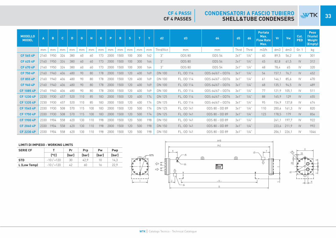
33CONDENSATORI A FASCIO TUBIEROSHELL&TUBE CONDENSERS
CF 4 PASSICF 4 PASSES
MODELLO MODEL A B C D G H K P R S T Y d2 d3 d4 d5 d6
Portata Max.
Flow Rate Max.
Vr Vw Cat. PED
Peso (Vuoto) Weight (Empty)
mm mm mm mm mm mm mm mm mm mm mm mm Thrd/Vict mm mm Thrd Thrd m3/h dm3 dm3 Gr. 1 kg
CF 565 4P 2160 1950 324 380 60 60 173 2000 1500 100 300 162 3” ODS 80 ODS 54 2x1” 1/4” 40 89,5 56,2 IV 301
CF 625 4P 2160 1950 324 380 60 60 173 2000 1500 100 300 164 3” ODS 80 ODS 54 2x1” 1/4” 45 82,8 61,5 IV 312
CF 670 4P 2160 1950 324 380 60 60 173 2000 1500 100 300 164 3” ODS 80 ODS 54 2x1” 1/4” 48 78,4 65 IV 320
CF 750 4P 2160 1940 406 480 90 80 178 2000 1500 120 400 169 DN 100 FL. OD 114 ODS 64/67 – OD76 3x1” 1/4” 54 157,1 76,7 IV 452
CF 855 4P 2160 1940 406 480 90 80 178 2000 1500 120 400 169 DN 100 FL. OD 114 ODS 64/67 – OD76 3x1” 1/4” 61 146,1 85,6 IV 470
CF 960 4P 2160 1940 406 480 90 80 178 2000 1500 120 400 169 DN 100 FL. OD 114 ODS 64/67 – OD76 3x1” 1/4” 68 135,1 94,5 IV 489
CF 1085 4P 2160 1940 406 480 90 80 178 2000 1500 120 400 169 DN 100 FL. OD 114 ODS 64/67 – OD76 3x1” 1/4” 77 121,9 105,1 IV 511
CF 1230 4P 2230 1930 457 520 110 85 183 2000 1500 120 400 174 DN 125 FL. OD 114 ODS 64/67 – OD76 3x1” 1/4” 88 165,9 129 IV 655
CF 1335 4P 2230 1930 457 520 110 85 183 2000 1500 120 400 174 DN 125 FL. OD 114 ODS 64/67 – OD76 3x1” 1/4” 95 154,9 137,8 IV 674
CF 1545 4P 2330 1930 508 570 115 100 183 2000 1500 120 500 174 DN 125 FL. OD 141 ODS 80 - OD 89 3x1” 1/4” 110 200,4 161,3 IV 820
CF 1750 4P 2330 1930 508 570 115 100 183 2000 1500 120 500 174 DN 125 FL. OD 141 ODS 80 - OD 89 3x1” 1/4” 123 178,5 179 IV 856
CF 1900 4P 2330 1904 558 620 130 110 198 2000 1500 120 500 198 DN 150 FL. OD 141 ODS 80 - OD 89 3x1” 1/4” 241,1 197,7 IV 922
CF 2060 4P 2330 1904 558 620 130 110 198 2000 1500 120 500 198 DN 150 FL. OD 141 ODS 80 - OD 89 3x1” 1/4” 223,6 211,9 IV 992
CF 2230 4P 2330 1904 558 620 130 110 198 2000 1500 120 500 198 DN 150 FL. OD 141 ODS 80 - OD 89 3x1” 1/4” 206,1 226,1 IV 1046
LIMITI DI IMPIEGO - WORKING LIMITS
SERIE CF T Pr Prp Pw Pwp
[°C] [bar] [bar] [bar] [bar]
STD -10 / +120 30 42,9 10 14,3
L (Low Temp) -10 / +120 42 60 16 22,9
WTK Catalogo Tecnico - Technical Catalogue
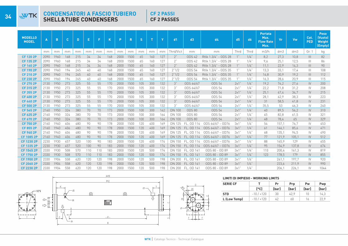
34 CONDENSATORI A FASCIO TUBIEROSHELL&TUBE CONDENSERS
CF 2 PASSICF 2 PASSES
MODELLO MODEL A B C D E F K P R S T Y d1 d3 d4 d5 d6
Portata Max.
Flow Rate Max.
Vr Vw Cat. PED
Peso (Vuoto) Weight (Empty)
mm mm mm mm mm mm mm mm mm mm mm mm Thrd/Vict mm mm Thrd Thrd m3/h dm3 dm3 Gr. 1 kg
CF 120 2P 2090 1960 168 215 34 34 168 2000 1500 65 160 127 2” ODS 42 Rtlk 1.3/4” - ODS 28 1” 1/4” 8,2 27,3 10,8 III 82CF 135 2P 2090 1960 168 215 34 34 168 2000 1500 65 160 127 2” ODS 42 Rtlk 1.3/4” - ODS 28 1” 1/4” 9,6 25,1 12,5 III 86CF 160 2P 2090 1960 168 215 34 34 168 2000 1500 65 160 127 2” ODS 42 Rtlk 1.3/4” - ODS 28 1” 1/4” 11,1 22,9 14,3 III 90CF 190 2P 2090 1960 194 245 40 40 168 2000 1500 65 160 127 2”1/2 ODS 54 Rtlk 1.3/4” - ODS 35 1” 1/4” 13,3 33,1 17,4 III 108CF 210 2P 2090 1960 194 245 40 40 168 2000 1500 65 160 127 2”1/2 ODS 54 Rtlk 1.3/4” - ODS 35 1” 1/4” 14,8 30,9 19,2 III 112CF 230 2P 2090 1960 194 245 40 40 168 2000 1500 65 160 127 2”1/2 ODS 54 Rtlk 1.3/4” - ODS 35 1” 1/4” 16,3 28,6 20,9 III 115CF 270 2P 2130 1950 273 325 55 55 170 2000 1500 105 300 132 3” ODS 64/67 ODS 54 2x1” 1/4” 19,2 76,2 27,6 IV 200CF 315 2P 2130 1950 273 325 55 55 170 2000 1500 105 300 132 3” ODS 64/67 ODS 54 2x1” 1/4” 22,2 71,8 31,2 IV 208CF 355 2P 2130 1950 273 325 55 55 170 2000 1500 105 300 132 3” ODS 64/67 ODS 54 2x1” 1/4” 25,1 67,4 34,7 IV 215CF 400 2P 2130 1950 273 325 55 55 170 2000 1500 105 300 132 3” ODS 64/67 ODS 54 2x1” 1/4” 28,1 62,9 38,3 IV 223CF 440 2P 2130 1950 273 325 55 55 170 2000 1500 105 300 132 3” ODS 64/67 ODS 54 2x1” 1/4” 31 58,5 41,8 IV 231CF 500 2P 2130 1950 273 325 55 55 170 2000 1500 105 300 132 3” ODS 64/67 ODS 54 2x1” 1/4” 35,5 53 46,3 IV 240CF 565 2P 2160 1950 324 380 70 70 173 2000 1500 100 300 162 DN 100 ODS 80 ODS 54 2x1” 1/4” 40 89,5 56,2 IV 310CF 625 2P 2160 1950 324 380 70 70 173 2000 1500 100 300 164 DN 100 ODS 80 ODS 54 2x1” 1/4” 45 82,8 61,5 IV 321CF 670 2P 2160 1950 324 380 70 70 173 2000 1500 100 300 164 DN 100 ODS 80 ODS 54 2x1” 1/4” 48 78,4 65 IV 329CF 750 2P 2160 1940 406 480 90 90 178 2000 1500 120 400 169 DN 125 FL. OD 114 ODS 64/67 – OD76 3x1” 1/4” 54 157,1 76,7 IV 453CF 855 2P 2160 1940 406 480 90 90 178 2000 1500 120 400 169 DN 125 FL. OD 114 ODS 64/67 – OD76 3x1” 1/4” 61 146,1 85,6 IV 471CF 960 2P 2160 1940 406 480 90 90 178 2000 1500 120 400 169 DN 125 FL. OD 114 ODS 64/67 – OD76 3x1” 1/4” 68 135,1 94,5 IV 490
CF 1085 2P 2160 1940 406 480 90 90 178 2000 1500 120 400 169 DN 125 FL. OD 114 ODS 64/67 – OD76 3x1” 1/4” 77 121,9 105,1 IV 512CF 1230 2P 2230 1930 457 520 100 90 183 2000 1500 120 400 174 DN 150 FL. OD 114 ODS 64/67 – OD76 3x1” 1/4” 88 165,9 129 IV 655CF 1335 2P 2230 1930 457 520 100 90 183 2000 1500 120 400 174 DN 150 FL. OD 114 ODS 64/67 – OD76 3x1” 1/4” 95 154,9 137,8 IV 674CF 1545 2P 2330 1930 508 570 110 110 183 2000 1500 120 500 174 DN 150 FL. OD 141 ODS 80 - OD 89 3x1” 1/4” 110 200,4 161,3 IV 819CF 1750 2P 2330 1930 508 570 110 110 183 2000 1500 120 500 174 DN 150 FL. OD 141 ODS 80 - OD 89 3x1” 1/4” 123 178,5 179 IV 855CF 1900 2P 2330 1904 558 620 120 120 198 2000 1500 120 500 198 DN 200 FL. OD 141 ODS 80 - OD 89 3x1” 1/4” 241,1 197,7 IV 920CF 2060 2P 2330 1904 558 620 120 120 198 2000 1500 120 500 198 DN 200 FL. OD 141 ODS 80 - OD 89 3x1” 1/4” 223,6 211,9 IV 990CF 2230 2P 2330 1904 558 620 120 120 198 2000 1500 120 500 198 DN 200 FL. OD 141 ODS 80 - OD 89 3x1” 1/4” 206,1 226,1 IV 1044
LIMITI DI IMPIEGO - WORKING LIMITS
SERIE CF T Pr Prp Pw Pwp
[°C] [bar] [bar] [bar] [bar]
STD -10 / +120 30 42,9 10 14,3
L (Low Temp) -10 / +120 42 60 16 22,9
WTK Catalogo Tecnico - Technical Catalogue

35CONDENSATORI A FASCIO TUBIEROSHELL&TUBE CONDENSERS
POSSIBILI APPLICAZIONI SERIE CFPOSSIBLE APPLICATIONS OF SERIES CF
WTK Catalogo Tecnico - Technical Catalogue

36 SEPARATORI D’OLIO E RICEVITORI DI LIQUIDOOIL SEPARATORS AND LIQUID RECEIVERS

37SEPARATORI D’OLIOOIL SEPARATORS
MODELLI RS - ECOLa funzione dell’applicazione dei separatori d’olio, installati a valle dei compressori a vite, è quella di separare l’olio lubrificante dal fluido frigorigeno riducendo il quantitativo d’olio in circolazione nel circuito e migliorando così il rendimento dell’impianto. I refrigeranti sono tutti gli HCFC, HFC, HFO, NH3 ed altri purché compatibili con i materiali di costruzione. I nostri separatori d’olio verticali hanno una capacità di separazione, per compressori a vite, adeguata per portate di refrigerante (di marche primarie) comprese tra 120 e 2250 m3/h.Il separatore è costituito da due parti: la superiore opportunamente dimensionata per ottenere una ele-vata separazione dell’olio dal gas refrigerante e quella inferiore dove l’olio separato cola e si accumula per poi essere di nuovo inviato verso il compressore (tranne versione ECO). La nostra gamma si distingue per offrire soluzioni con e senza ricevitore e con separazione mono stadio (ciclonica) oppure bi stadio (ciclonica e filtrante).Tutti i separatori d’olio sono sottoposti ad una prova pressione per il controllo della tenuta generale e specifica delle saldature.
MODELS RS -ECOThe purpose of the application of the oil separators, installed after the screw compressors, is the one to separate the lubricant oil from the refrigerant fluid reducing the quantity of oil in circulation in the plant thus improving the overall efficiency. The refrigerants are all the HCFC, HFC, HFO, NH3 and others as long as compatible with the manufacturing materials. Our vertical oil separators have a separation capacity, for screw compressors, suitable for refrigerant flows (of primary brands) included between 120 and 2250 m3/h.The separator consists of two sections: the higher one which is adequately designed to obtain a high de-gree of separation of the oil from the refrigerant gas and a lower one where the separated oil drops and accumulates to be later on sent back to the compressor (except ECO version). Our range offers solutions with and without receiver and with single stage (cyclonic) or double stage (cyclonic and filtering).All the oil separators are submitted to a pressure test to check the general tightness and the quality of the weldings.
MODELLO COMPRESSOR SUCTION VOLUME OIL
VOLUMETOTAL
VOLUME PS TS A B C D E P R
CONNECTIONSCat. PED
Peso (Vuoto) Weight (Empty)MODEL Air Condi-
tioning
Coooling and Low
Temp.d1 d2 d3
m3/h m3/h dm3 dm3 bar °C mm mm mm mm mm mm mm mm mm Thrd Gr. 1 kg
RS182 220 300 3 30 30 -10 / +90 545 385 100 324 114 115 230 ODS 54 - OD 60 ODS 54 - OD 60 1/2” III 38
RS402 490 660 7 75 30 -10 / +120 770 560 170 406 168 150 230 ODS 64 - OD 76 ODS 64 - OD 76 1” IV 55
RS902 940 1320 10 140 30 -10 / +120 900 640 180 508 219 198 277 ODS 80 - OD 89 ODS 80 - OD 89 1” IV 66
CONNESSIONI CONNECTIONS
1 Refrigerant inlet
2 Refrigerant outlet
3 Oil outlet
4 Safety valve connection
5 Secondary oil outlet
LIMITI DI IMPIEGO - WORKING LIMITS
RS T Pr Prp
[°C] [bar] [bar]
RS 182 / 402 / 902 -10 / +120 36 51,5
SERIE RSSERIES RS

38 SEPARATORI D’OLIO E RICEVITORI DI LIQUIDOOIL SEPARATORS AND LIQUID RECEIVERS
MODELLOMODEL
COMPRESSOR SUCTION VOLUME MAX
COMPRESSORS NUMBER
OIL VOLUME
OIL VOLUME
TOTAL VOLUME PS TS A B C D E F G H M N P R
CONNECTIONSCat. PED
Peso (Vuoto) Weight (Empty)
Air Conditioning
Coooling and Low Temp. d3 d4 d7
m3/h m3/h N° dm3 dm3 dm3 bar °C mm mm mm mm mm mm mm mm mm mm mm mm mm mm Thrd Gr. 1 kg
RS180 220 300 2 19 19 50 36 -10 / +120 830 200 240 324 550 280 330 330 420 100 120 13 OD 54 OD 54 1”1/4 Rtk IV 60
RS400 490 660 3 50 50 120 36 -10 / +120 1170 220 260 406 865 320 380 460 550 100 145 13 OD 76 OD 76 1”3/4 Rtk IV 130
RS900 940 1320 6 90 90 220 36 -10 / +120 1480 280 300 508 1105 440 500 560 650 100 198 18 OD 89 OD 89 ODS 42 IV 195
RS1300 1320 1600 6 130 130 330 32 -45 / +120 1485 300 320 610 1100 530 610 550 650 135 235 18 OD 114 OD 114 ODS 54 IV 230
RS2300 1650 2250 6 230 230 560 32 -45 / +120 1770 380 360 711 1320 530 610 710 760 150 265 18 OD 141 OD 141 ODS 76 IV 385
CONNESSIONI CONNECTIONS
1 Refrigerant outlet
2 Service valve connection
3 Refrigerant Inlet
4 Oil charge valve connection
5 Oil level sight glass
6 Parallel compressors oil outlet
7 Oil control level connection
8 Oil outlet
9 Oil heaters connection
10 Safety valve connection
11 Thermostat sensor connection
LIMITI DI IMPIEGO - WORKING LIMITS
RS T Pr Prp
[°C] [bar] [bar]
RS 180 / 400 / 900 -10 / +120 36 51,5
RS 1300 / 2300 -45 / +120 32 45,8
SEPARATORI D’OLIOOIL SEPARATORS
SERIE RS - MONOSTADIOSERIES RS - 1 STAGE
WTK Catalogo Tecnico - Technical Catalogue

CONNESSIONI CONNECTIONS
1 Refrigerant outlet
2 Service valve connection
3 Refrigerant Inlet
4 Oil charge valve connection
5 Oil level sight glass
6 Parallel compressors oil outlet
7 Oil control level connection
8 Oil outlet
9 Oil heaters connection
10 Safety valve connection
11 Thermostat sensor connection
LIMITI DI IMPIEGO - WORKING LIMITS
RS T Pr Prp
[°C] [bar] [bar]
RS 180 / 404 / 904 -10 / +120 36 51,5
RS 1304 / 2304 -45 / +120 32 45,8
39SEPARATORI D’OLIOOIL SEPARATORS
MODELLOMODEL
COMPRESSOR SUCTION VOLUMEMAX
COMPRESSORS NUMBER
OIL VOLUME
TOTAL VOLUME PS TS A B C D E F G H M N P R S
CONNECTIONSCat. PED
Peso (Vuoto) Weight (Empty)
Air Conditioning Coooling
Coooling and Low
Temp.d3 d4 d7
m3/h m3/h m3/h N dm3 dm3 bar °C mm mm mm mm mm mm mm mm mm mm mm mm mm mm mm Thrd Gr. 1 kg
RS184 120 150 250 2 21 90 36 -10 / +120 1336 200 240 324 680 280 330 350 440 725 120 13 1050 ODS 54 / OD 60 ODS 54 / OD 60 1”1/4 Rtk IV 145
RS404 220 300 500 3 50 170 36 -10 / +120 1620 220 260 406 820 320 380 460 550 895 145 13 1310 ODS 64 / OD 76 ODS 64 / OD 76 1”3/4 Rtk IV 185
RS904 400 550 950 6 90 310 36 -10 / +120 1950 260 300 508 1060 440 500 520 610 1135 198 18 1550 ODS 80 / OD 89 ODS 80 / OD 89 ODS 42 IV 345
RS1304 960 1200 1350 6 130 470 32 -45 / +120 2005 300 320 610 1220 530 610 550 650 1320 235 18 1610 ODS 108 / OD 114 ODS 108 / OD 114 ODS 54 IV 465
RS2304 1300 1650 2250 6 220 620 32 -45 / +120 2250 385 385 711 1365 530 610 695 715 1465 265 18 1805 OD 141 OD 141 ODS 76 IV 600
SERIE RS- BISTADIOSERIES RS - 2 STAGE
WTK Catalogo Tecnico - Technical Catalogue

40 SEPARATORI D’OLIO E RICEVITORI DI LIQUIDOOIL SEPARATORS AND LIQUID RECEIVERSRICEVITORI DI LIQUIDOLIQUID RECEIVERS
SERIE HLRSERIES HLR
MODELLI HLRI ricevitori di liquido serie HLR sono quelli costruiti in versione orizzontale.La gamma standard comprende modelli con volumi da circa 30 litri a 1000 litri, ma sono possibili anche esecuzioni speciali con dimensioni maggiori.Le opzioni disponibili sono staffe saldate, spie di liquido, connessioni extra.
MODELS HLRThe liquid receivers series HLR are the ones manufactured in horizontal execution.The standard range includes models with volumes from about 30 litres to 1000 litres, but special versions are also feasible with larger size.The options available are welded feet, sight glasses, extra sockets.
MODELLO MODEL VOLUME PS TS A B C D E F G d1 d2 d5 Cat.
PED
Peso (Vuoto) Weight (Empty)
dm3 bar °C mm mm mm mm mm mm mm mm mm Thrd Gr. 1 kg
HLR 30 31 40 -10 / 120 920 550 560
219 70 80 260 Rtlk 1.3/4” - ODS35 Rtlk 1.3/4” - ODS35 1/2” NPT
III 35HLR 40 40 40 -10 / 120 1170 800 700 IV 39HLR 50 49 40 -10 / 120 1420 1050 900 IV 50HLR 60 57 40 -10 / 120 1670 1300 1000 IV 56HLR 70 64 36 -10 / 120 1200 800 700
273 50 100 300 ODS42 ODS42 1” NPIV 52
HLR 80 77 36 -10 / 120 1450 1050 900 IV 68HLR 90 90 36 -10 / 120 1700 1300 1000 IV 90
HLR 110 109 36 -10 / 120 1480 1050 900324 50 100 300 ODS54 ODS54 1” NPT
IV 91HLR 130 128 36 -10 / 120 1740 1300 1000 IV 108HLR 145 144 36 -10 / 120 1280 800 700
406 50 120 400 ODS54 ODS54 1”NPT
IV 120HLR 175 173 36 -10 / 120 1530 1050 900 IV 128HLR 200 203 36 -10 / 120 1780 1300 1000 IV 146HLR 260 262 36 -10 / 120 2280 1800 1200 IV 183HLR 320 318 36 -10 / 120 1830 1300 1000
508 50 120 400OD76 OD76
2X1” NPT
IV 230HLR 410 412 36 -10 / 120 2330 1800 1200 IV 326HLR 500 506 36 -10 / 120 2830 2300 1500
OD89 OD89IV 345
HLR 600 600 36 -10 / 120 3330 2800 2000 IV 420HLR 630 628 32 -10 / 120 2850 2300 1500
558 70 120 500 OD114 OD114 3X1” NPTIV 416
HLR 745 743 32 -10 / 120 3350 2800 2000 IV 480HLR 880 870 32 -45 / 120 3380 2800 2000
610 70 120 600 OD141 OD141 3X1” NPTIV 503
HLR 1000 999 32 -45 / 120 3880 3300 2200 IV 605
LIMITI DI IMPIEGO - WORKING LIMITS
HLR T Pr Prp
[°C] [bar] [bar]
HLR 30 / 60 -10 / +120 40 57,2
HLR 70 / 600 -10 / +120 36 51,5
HLR 630 / 745 -10 / +120 32 45,8
HLR 800 / 1000 -45 / +120 32 45,8
WTK Catalogo Tecnico - Technical Catalogue

41RICEVITORI DI LIQUIDOLIQUID RECEIVERS
SERIE VLRSERIES VLR
LIMITI DI IMPIEGO - WORKING LIMITS
VLR T Pr Prp
[°C] [bar] [bar]
VLR 30 / 60 -10 / +120 40 57,2
VLR 70 / 410 -10 / +120 36 51,5
MODELLO MODEL VOLUME PS TS A B C D E F G H d1 d2 d5 Cat.
PED
Peso (Vuoto) Weight (Empty)
dm3 bar °C mm mm mm mm mm mm mm mm mm mm inch Gr. 1 kg
VLR 30 31 40 -10 / +120 950 550
215 219 70 270 210 13 Rtlk 1.3/4” - ODS35 Rtlk 1.3/4” - ODS35 1/2” NPT
IV 37
VLR 40 40 40 -10 / +120 1200 800 IV 41
VLR 50 49 40 -10 / +120 1450 1050 IV 52
VLR 60 57 40 -10 / +120 1700 1300 IV 56
VLR 70 64 36 -10 / +120 1230 800
230 273 50 270 210 13 ODS42 ODS42 1” NPT
IV 54
VLR 80 77 36 -10 / +120 1480 1050 IV 70
VLR 90 90 36 -10 / +120 1730 1300 IV 92
VLR 110 109 36 -10 / +120 1520 1050250 324 50 330 280 13 ODS54 ODS54 1” NPT
IV 94
VLR 130 128 36 -10 / +120 1770 1300 IV 111
VLR 145 144 36 -10 / +120 1330 800
290 406 50 380 320 13 ODS54 ODS54 1”NPT
IV 124
VLR 175 173 36 -10 / +120 1580 1050 IV 132
VLR 200 209 36 -10 / +120 1830 1300 IV 150
VLR 260 262 36 -10 / +120 2330 1800 IV 187
VLR 320 318 36 -10 / +120 1880 1300315 508 50 500 440 18 OD76 OD76 2X1” NPT
IV 231
VLR 410 412 36 -10 / +120 2380 1800 IV 330
MODELLI VLRI ricevitori di liquido serie VLR sono quelli costruiti in versione verticale.La gamma standard comprende modelli con volumi da circa 30 litri a 450 litri, ma sono possibili anche esecuzioni speciali con dimensioni maggiori.Le opzioni disponibili sono staffe saldate, spie di liquido, connessioni extra.
MODELS VLRThe liquid receivers series VLR are the ones manufactured in vertical execution.The standard range includes models with volumes from about 30 litres to 450 litres, but special versions are also feasible with larger size.The options available are welded feet, sight glasses, extra sockets.
WTK Catalogo Tecnico - Technical Catalogue

42 PIASTRE SALDO-BRASATEBRAZED PLATES
SERIE BPHESERIES BPHE
WTK Catalogo Tecnico - Technical Catalogue

43PIASTRE SALDO-BRASATEBRAZED PLATES
MODELLI P4 – P7 – NP7 – P12 – P15 – P16 – P30Tutti gli scambiatori a piastre WTK sono costruiti con piastre in acciaio inossidabile AISI304, saldobrasate utilizzando rame puro (Cu 99,9%). La costruzione dello scambiatore viene eseguita sovrapponendo le piastre in acciaio ruotate di 180° ed interponendo tra di esse un foglio di rame sagomato come la piastra. In questo modo si creano le camere in cui i fluidi possono circolare.Le opzioni disponibili sono perni di fissaggio, staffe di supporto e golfari, connessioni Victaulic o flangiate, connessioni extra per sensori, isolamento termico spessore 10mm, connessioni anche sul retro, versione alta pressione (45 bar tranne P4).Tutti i modelli BPHE prodotti da WTK sono certificati PED-CE (Dir. 2014/68/UE) ed hanno superato i test in pressione e sotto vuoto previsti. I controlli vengono effettuati in base al manuale interno di qualità UNI EN ISO 9001 e specificatamente tutti gli scambiatori a piastre sono sottoposti mediante a test di pressione per mezzo di sistemi automa-tizzati.
APPLICAZIONI DEI VARI MODELLIP4 = acqua/acqua, raffreddatore d’olioP7 = acqua/acqua, raffreddatore d’olio, evaporatore, condensatore, pompa di calore, economizzatore, desurriscaldatoreNP7 = evaporatore, condensatore, pompa di caloreP12 = acqua/acqua, raffreddatore d’olio, evaporatore, condensatore, pompa di caloreP15 = acqua/acqua, raffreddatore d’olio, evaporatore, condensatore, pompa di calore, economizzatore, desurriscaldatoreP16 = evaporatoreP30 = acqua/acqua, raffreddatore d’olio, evaporatore, condensatore, economizzatore, desurriscaldatore
MODELS P4 – P7 – NP7 – P12 – P15 – P16 – P30All the brazed plates WTK are manufactured with stainless steel AISI304 plates and brazed with pure copper (Cu 99,9%). The assembly of the heat exchanger is done overlapping the stainless steel plates rotated of 180° with an intermediate plate-shaped copper foil. This way the chambers for the circulation of the fluids are created.The available options are fixing studbolts, feet and lifting lugs, Victaulic or flanged connections, extra sockets for sensors, thermal insulation thickness 10mm, connections on the back side, high pressure version (45 bar except P4).All models BPHE produced by WTK are certified PED-CE (Dir. 2014/68/UE) and have successfully passed the necessary pressure and vacuum tests. The quality checks are in compliance with the internal quality system manual UNI EN ISO 9001 and spe-cifically all the brazed plates are submitted to pressure tests carried out by automatized systems.
APPLICATIONS OF THE VARIOUS MODELSP4 = water/water, oil coolerP7 = water/water, oil cooler, evaporator, condenser, heat pump, economizer, desuperheaterNP7 = evaporator, condenser, heat pumpP12 = water/water, oil cooler, evaporator, condenser, heat pumpP15 = water/water, oil cooler, evaporator, condenser, heat pump, economizer, desuperheaterP16 = evaporatorP30 = water/water, oil cooler, evaporator, condenser, economizer, desuperheater
SERIE BPHESERIES BPHE
WTK Catalogo Tecnico - Technical Catalogue

44 SEPARATORI D’OLIO E RICEVITORI DI LIQUIDOOIL SEPARATORS AND LIQUID RECEIVERSPIASTRE SALDO-BRASATEBRAZED PLATES
SERIE BPHESERIES BPHE
LIMITI DI IMPIEGO - WORKING LIMITS
BPHE T Pr Prp Pw Pwp
[°C] [bar] [bar] [bar] [bar]
STD -160 / +200 30 42,9 30 42,9
HP -160 / +150 45 64,4 45 64,4
B
A
C
E
FD
TOP BOTTOM
C
D
B
A
F
E
TOP BOTTOM
C
D
B
A
F
E
TOP BOTTOM
B
A E
C
D
TOP BOTTOM
F
MODELLO Volume per singolo canale Volume per single channel A B C D E F G H Peso (vuoto)
Weight (empty)MODEL
dm3 mm mm mm mm mm mm mm mm kg
P4 0.056 310 111 2,625 x N + 4 27 50 50 - - 0,132 x N + 0,8
MODELLO Volume per singolo canale Volume per single channel A B C D E F G H Peso (vuoto)
Weight (empty)MODEL
dm3 mm mm mm mm mm mm mm mm kg
P7 0.12 526 120 2,31 x N + 4 27 66.3 66.3 - - 0,20 x N + 2,3
MODELLO Volume per singolo canale Volume per single channel A B C D E F G H Peso (vuoto)
Weight (empty)MODEL
dm3 mm mm mm mm mm mm mm mm kg
NP7 0.12 526 120 2,31 x N + 4 27 66.3 66.3 - - 0,20 x N + 2,3
MODELLO Volume per singolo canale Volume per single channel A B C D E F G H Peso (vuoto)
Weight (empty)MODEL
dm3 mm mm mm mm mm mm mm mm kg
P12 0.2 617 188 2,33 x N + 6 27 92 92 - - 0,38 x N + 7,8
WTK Catalogo Tecnico - Technical Catalogue

45PIASTRE SALDO-BRASATEBRAZED PLATES
SERIE BPHESERIES BPHE
LIMITI DI IMPIEGO - WORKING LIMITS
BPHE T Pr Prp Pw Pwp
[°C] [bar] [bar] [bar] [bar]
STD -160 / +200 30 42,9 30 42,9
HP -160 / +150 45 64,4 45 64,4
B
A E
C
DF
TOP BOTTOM
EA
F
B C
H D
G
TOP BOTTOM
TOP BOTTOM
B
A
D
E
F
C
MODELLO Volume per singolo canale Volume per single channel A B C D E F G H Peso (vuoto)
Weight (empty)MODEL
dm3 mm mm mm mm mm mm mm mm kg
P15 0.27 530 265 2,31 x N + 8 27 439 177 - - 0,41 x N + 8,1
MODELLO Volume per singolo canale Volume per single channel A B C D E F G H Peso (vuoto)
Weight (empty)MODEL
dm3 mm mm mm mm mm mm mm mm kg
P16 0.27 530 265 2,31 x N + 8 27 439 177 397 26 0,41 x N + 8,1
MODELLO Volume per singolo canale Volume per single channel A B C D E F G H Peso (vuoto)
Weight (empty)MODEL
dm3 mm mm mm mm mm mm mm mm kg
P30 0.53 782 350 2,9 x N + 6 27 655 220 - - 0,86 x N + 16,1
WTK Catalogo Tecnico - Technical Catalogue