TECHNICAL APPROVAL ACCORDING TO TL/TP FÜ … · TECHNICAL APPROVAL ACCORDING TO TL/TP FÜ (Stand:...
48
SWIVEL JOIST-EXPANSION JOINTS (with/without noise reduction) TECHNICAL APPROVAL ACCORDING TO TL/TP FÜ (Stand: 03/05) According to the requirements of: German Federal Ministry of Transportation, Building Industry and Housing Department for Road construction, Road Traffic / Department S 18 Robert-Schuman-Platz 1 D-53175 Bonn Inspector: External controller: Mister German Federal Materials Testing Insti- tute Dipl.-Ing. Winfried Neumann University Stuttgart Homertstr. 10 Pfaffenwaldring 32 D-58091 Hagen - Dahl D-70569 Stuttgart Technical Approval of static and construction engineering aspect according to TL/TP FÜ (Stand: 03/05) tested, see Inspection report-Nr.: 05/2007 dated 20.12.2007 .............................................................. Dipl.-Ing. W. Neumann, 58091 Hagen
-
Upload
vuongkhanh -
Category
Documents
-
view
260 -
download
0
Transcript of TECHNICAL APPROVAL ACCORDING TO TL/TP FÜ … · TECHNICAL APPROVAL ACCORDING TO TL/TP FÜ (Stand:...
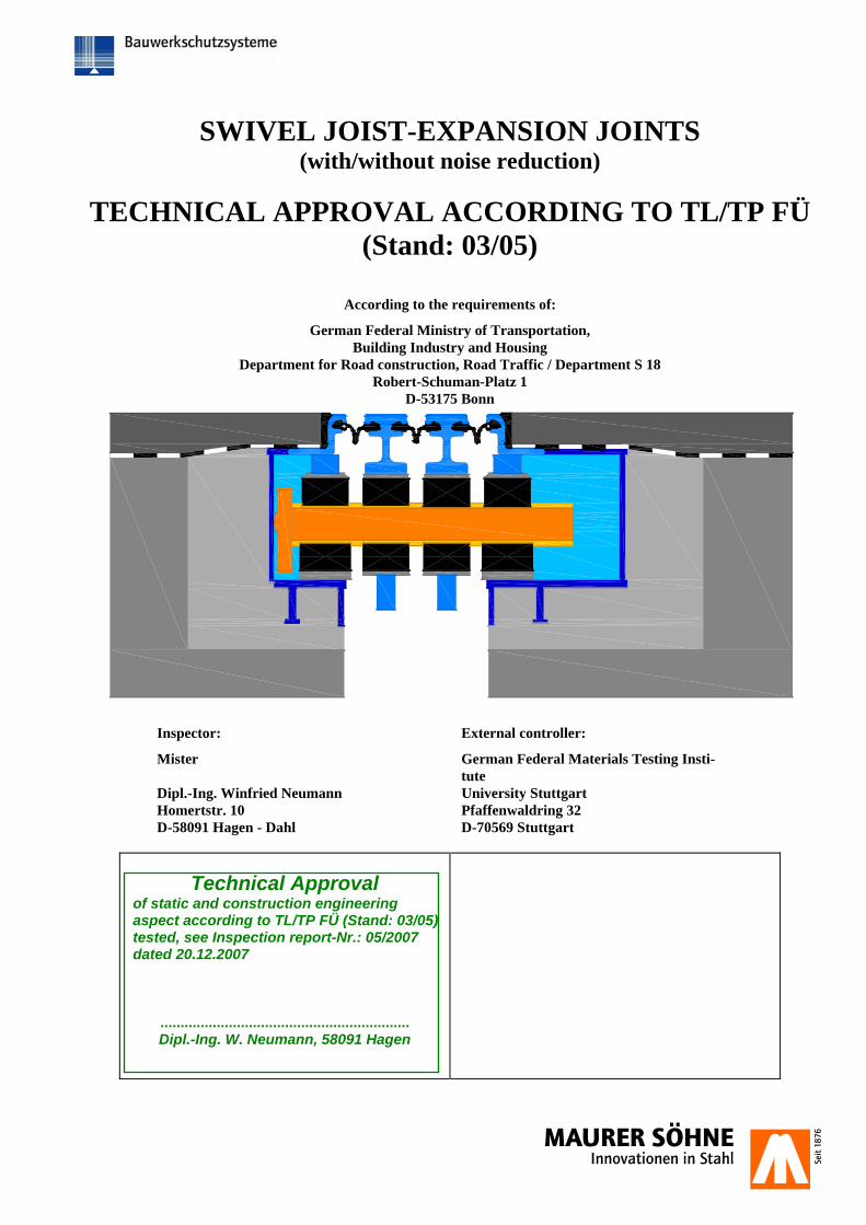
SWIVEL JOIST-EXPANSION JOINTS (with/without noise reduction)
TECHNICAL APPROVAL ACCORDING TO TL/TP FÜ (Stand: 03/05)
According to the requirements of:
German Federal Ministry of Transportation, Building Industry and Housing
Department for Road construction, Road Traffic / Department S 18 Robert-Schuman-Platz 1
D-53175 Bonn
Inspector: External controller:
Mister German Federal Materials Testing Insti-tute
Dipl.-Ing. Winfried Neumann University Stuttgart Homertstr. 10 Pfaffenwaldring 32 D-58091 Hagen - Dahl D-70569 Stuttgart
Technical Approval of static and construction engineering aspect according to TL/TP FÜ (Stand: 03/05) tested, see Inspection report-Nr.: 05/2007 dated 20.12.2007
.............................................................. Dipl.-Ing. W. Neumann, 58091 Hagen
VERFASSER :
BAUWERK : STRASSEN- UND WEGBRÜCKEN DATUM: 01.12.2007
BAUTEIL : SCHWENKTRAVERSEN-DEHNFUGE DS160 BIS 1200
BLOCK : UNTERLAGEN MIT REGELPRÜFVERMERK
VORGANG : REGELPRÜFUNG NACH TL/TP FÜ (STAND: 03/05)
ARCHIV NR.
Regelprüfung Nr. 05/07 vom 20.12.07
Diese Unterlagen sind Eigentum der MAURER SÖHNE GmbH & Co. KG. Jede Art der Vervielfältigung - auch auszugsweise - bedarf der Zustimmung.
Formate und Inhalte sind urheberrechtlich geschützt!
M A N U A L
CONTENTS
Chapter Title Page
0. Field of Application 1 1. Persons in charge 1
1.1 Applicant and Operator 1 1.2 Manufacturer of the expansion joint 1 1.3 Manufacturer of special components 1 1.4 Quality Assurance 2 1.5 Approval and Tests 2 1.6 Manufacturer’s declaration 2
2. Description of the system 3 2.1 General 3-4 2.2 Type STW 4 2.3 Type STP 5 2.4 Force Transfer of the Wheel Loads 5-6 2.5 Elastic support of joists 6 2.6 Anchorage 6 2.7 Sealing profile 6-7 2.8 Noise reduction (optional) 7-8
3. Hints for the user 9 3.1 Checklist for Planning and Inspection 9 3.2 Overview of the allowed movements determined within the scope of the Technical approval 10-12 3.3 Additional regulatory framework for the use of rhombic elements 13-15 3.4 Recess-sizes 16-18 3.5 Anchoring powers 19
4. Construction requirements for the technically approved expansion joints 20 4.1 Allowed cross bar interspaces and the arrangement of the joints 20 4.2 Arrangement of joists in the footway 21 4.3 Factory provided corrosion protection 22
5. Installation instructions 23 5.1 Delivery 23 5.2 Assembly and structural connection 23-26 5.3 Anchoring in the cap area 26 5.4 Procedure for bridges with steel carriageways 27 5.5 Control of installation dimension 26-27 5.6 Sealing of the structure 28 5.7 Further information 29 5.8 Site joints 30-32 Appen-dix
Certificate of acceptance / Installation record 33
6. Information for maintenance, preservation and removal of wear and tear parts 34 6.1 Accessibility 34 6.2 Constructional Elements Subjected to Continuous Checking 35-36 6.3 Replacing the sealing elements 36 6.4 Replacing the wear and tear elements from the carriageway direction 37-38
7. Construction plans and parts lists 39 Appendix Seven drawings
Inspection Report (2 pages)
VERFASSER :
BAUWERK : STRASSEN- UND WEGBRÜCKEN DATUM: 01.12.2007
BAUTEIL : SCHWENKTRAVERSEN-DEHNFUGE DS160 BIS 1200
BLOCK : 1 - VERANTWORTLICHE SEITE: 1
VORGANG : REGELPRÜFUNG NACH TL/TP FÜ (STAND: 03/05)
ARCHIV NR.
Regelprüfung Nr. 05/07 vom 20.12.07
Diese Unterlagen sind Eigentum der MAURER SÖHNE GmbH & Co. KG. Jede Art der Vervielfältigung - auch auszugsweise - bedarf der Zustimmung.
Formate und Inhalte sind urheberrechtlich geschützt!
0. Field of Application
Due to the implementation of the Version 12/07 the hitherto valid Version of December 02, 2003 is now void. The technical approval covers Construction of frequently repeated methods of construction. Currently the-re are the following limitations of the range of use to be considered:
- The carriageway may not exceed 10% of the transverse slope - The carriageway may not exceed 9% of the slope with the DS640 type and 6% of the slope with larger
types - Allowed movements given by the Table 3.2 are to be considered. - According to the ground plan, direction changes of the joint design are allowed only with Type STW
between - the lying carriageway outside cross bar (joist) and the cornice or footway cross bar - For noise reduction the use of rhombic elements is possible only between 60° ≤ α ≤ 120°.
Deviations from the above limitations and subsequent specifications are possible, but they require however a test for each single case separately.
1. Persons in charge 1.1 Applicant and Operator
MAURER SÖHNE GmbH & Co. KG Technical Office Munich Frankfurter Ring 193 Dr. Ch. Braun, Mr. B. Volk 80807 Munich 1.2 Manufacturer of the expansion joint
MAURER SÖHNE GmbH & Co. KG Technical Offices: Manufacturing sites Installation crews
Frankfurter Ring 193 80807 Munich
Frankfurter Ring 193 80807 Munich
Frankfurter Ring 193 80807 Munich
Zum Holzplatz 2 44536 Lünen
Zum Holzplatz 2 44536 Lünen
Kamenzer Str. 53 02994 Bernsdorf
Kamenzer Str. 53 02994 Bernsdorf
Kamenzer Str. 53 02994 Bernsdorf
1.3 Manufacturer of special components
See "The List of approved suppliers" in the appendix of the companies' work instruction QSA 1.810 in current version.
VERFASSER :
BAUWERK : STRASSEN- UND WEGBRÜCKEN DATUM: 01.12.2007
BAUTEIL : SCHWENKTRAVERSEN-DEHNFUGE DS160 BIS 1200
BLOCK : 1 - VERANTWORTLICHE SEITE: 2
VORGANG : REGELPRÜFUNG NACH TL/TP FÜ (STAND: 03/05)
ARCHIV NR.
Regelprüfung Nr. 05/07 vom 20.12.07
Diese Unterlagen sind Eigentum der MAURER SÖHNE GmbH & Co. KG. Jede Art der Vervielfältigung - auch auszugsweise - bedarf der Zustimmung.
Formate und Inhalte sind urheberrechtlich geschützt!
1.4 Quality Assurance QS-System The quality management system meets the DIN EN ISO 9001 standards. It was certified by DVS-Zert. Monitoring The Monitoring is divided into external and internal supervision. The documents and working instructions that form the basis of this TECHNICAL APPROVAL will be tested on their compliance with these regula-tions. Responsible for the External Monitoring is the
German Federal Materials Testing Institute of the University Stuttgart Pfaffenwaldring 32/ D-70569 Stuttgart
1.5 Approval and Verifications Approvals for Welding Munich Factory "The Extensive Proof of Suitability" according to DIN 18800 Part 7, DIN 15018 (DIN 18809 included in DIN 15018), DIN 4099 and DS 804 Bernsdorf Factory "The Extensive Proof of Suitability" according to DIN 18800 Part 7, DIN 4099 and DS 804 (DIN 18809) Branch Lünen "The Extensive Proof of Suitability" according to DIN 18800 Part 7, DIN 18809, and DS 804 Approval of Factory Welders The condition required to obtain an Approval is a Licence according to DIN EN 287-1. Approval of site Welders According to component demands, only welders with a valid Verification Certificate according to DIN EN 287-1 and Concrete Reinforcement Steel Welder’s Verification according to DIN 4099 are deployed. The related verifica-tion is avaliable on the site. 1.6 Producer's statement MAURER SÖHNE GmbH & Co. KG herewith declare •Compliance with the design conditions of all documents with the test certificates, listed in the index from 1.12.2007 •Compliance with quality assurance standards listed in the supervision contract from 01st April 2002. Munich, 01st December 2007 Company Management Technical Office
VERFASSER :
BAUWERK : STRASSEN- UND WEGBRÜCKEN DATUM: 01.12.2007
BAUTEIL : SCHWENKTRAVERSEN-DEHNFUGE DS160 BIS 1200
BLOCK : 2 – BESCHREIBUNG DES SYSTEMS SEITE: 3
VORGANG : REGELPRÜFUNG NACH TL/TP FÜ (STAND: 03/05)
ARCHIV NR.
Regelprüfung Nr. 05/07 vom 20.12.07
Diese Unterlagen sind Eigentum der MAURER SÖHNE GmbH & Co. KG. Jede Art der Vervielfältigung - auch auszugsweise - bedarf der Zustimmung.
Formate und Inhalte sind urheberrechtlich geschützt!
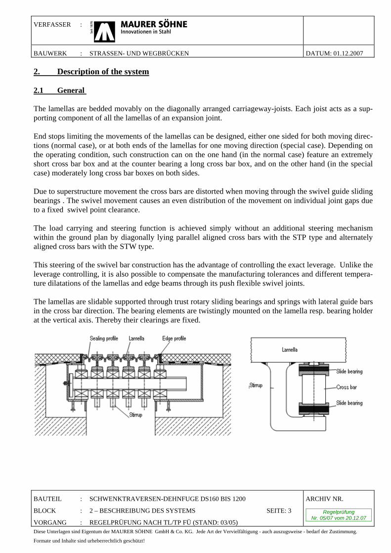
2. Description of the system 2.1 General The lamellas are bedded movably on the diagonally arranged carriageway-joists. Each joist acts as a sup-porting component of all the lamellas of an expansion joint. End stops limiting the movements of the lamellas can be designed, either one sided for both moving direc-tions (normal case), or at both ends of the lamellas for one moving direction (special case). Depending on the operating condition, such construction can on the one hand (in the normal case) feature an extremely short cross bar box and at the counter bearing a long cross bar box, and on the other hand (in the special case) moderately long cross bar boxes on both sides. Due to superstructure movement the cross bars are distorted when moving through the swivel guide sliding bearings . The swivel movement causes an even distribution of the movement on individual joint gaps due to a fixed swivel point clearance. The load carrying and steering function is achieved simply without an additional steering mechanism within the ground plan by diagonally lying parallel aligned cross bars with the STP type and alternately aligned cross bars with the STW type. This steering of the swivel bar construction has the advantage of controlling the exact leverage. Unlike the leverage controlling, it is also possible to compensate the manufacturing tolerances and different tempera-ture dilatations of the lamellas and edge beams through its push flexible swivel joints. The lamellas are slidable supported through trust rotary sliding bearings and springs with lateral guide bars in the cross bar direction. The bearing elements are twistingly mounted on the lamella resp. bearing holder at the vertical axis. Thereby their clearings are fixed.
VERFASSER :
BAUWERK : STRASSEN- UND WEGBRÜCKEN DATUM: 01.12.2007
BAUTEIL : SCHWENKTRAVERSEN-DEHNFUGE DS160 BIS 1200
BLOCK : 2 – BESCHREIBUNG DES SYSTEMS SEITE: 4
VORGANG : REGELPRÜFUNG NACH TL/TP FÜ (STAND: 03/05)
ARCHIV NR.
Regelprüfung Nr. 05/07 vom 20.12.07
Diese Unterlagen sind Eigentum der MAURER SÖHNE GmbH & Co. KG. Jede Art der Vervielfältigung - auch auszugsweise - bedarf der Zustimmung.
Formate und Inhalte sind urheberrechtlich geschützt!
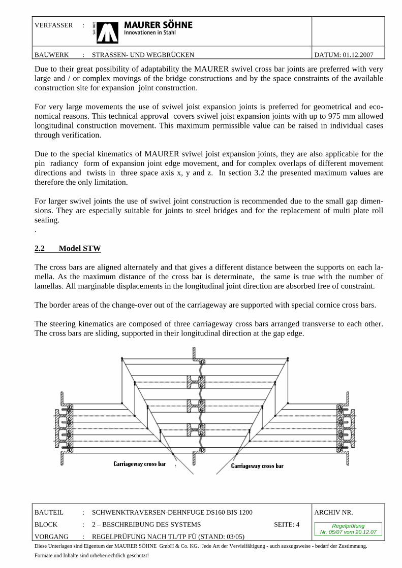
Due to their great possibility of adaptability the MAURER swivel cross bar joints are preferred with very large and / or complex movings of the bridge constructions and by the space constraints of the available construction site for expansion joint construction. For very large movements the use of sviwel joist expansion joints is preferred for geometrical and eco-nomical reasons. This technical approval covers sviwel joist expansion joints with up to 975 mm allowed longitudinal construction movement. This maximum permissible value can be raised in individual cases through verification. Due to the special kinematics of MAURER sviwel joist expansion joints, they are also applicable for the pin radiancy form of expansion joint edge movement, and for complex overlaps of different movement directions and twists in three space axis x, y and z. In section 3.2 the presented maximum values are therefore the only limitation. For larger swivel joints the use of swivel joint construction is recommended due to the small gap dimen-sions. They are especially suitable for joints to steel bridges and for the replacement of multi plate roll sealing. . 2.2 Model STW The cross bars are aligned alternately and that gives a different distance between the supports on each la-mella. As the maximum distance of the cross bar is determinate, the same is true with the number of lamellas. All marginable displacements in the longitudinal joint direction are absorbed free of constraint. The border areas of the change-over out of the carriageway are supported with special cornice cross bars. The steering kinematics are composed of three carriageway cross bars arranged transverse to each other. The cross bars are sliding, supported in their longitudinal direction at the gap edge.
VERFASSER :
BAUWERK : STRASSEN- UND WEGBRÜCKEN DATUM: 01.12.2007
BAUTEIL : SCHWENKTRAVERSEN-DEHNFUGE DS160 BIS 1200
BLOCK : 2 – BESCHREIBUNG DES SYSTEMS SEITE: 5
VORGANG : REGELPRÜFUNG NACH TL/TP FÜ (STAND: 03/05)
ARCHIV NR.
Regelprüfung Nr. 05/07 vom 20.12.07
Diese Unterlagen sind Eigentum der MAURER SÖHNE GmbH & Co. KG. Jede Art der Vervielfältigung - auch auszugsweise - bedarf der Zustimmung.
Formate und Inhalte sind urheberrechtlich geschützt!
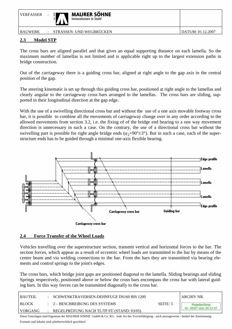
2.3 Model STP The cross bars are aligned parallel and that gives an equal supporting distance on each lamella. So the maximum number of lamellas is not limited and is applicable right up to the largest extension paths in bridge construction. Out of the carriageway there is a guiding cross bar, aligned at right angle to the gap axis in the central position of the gap. The steering kinematic is set up through this guiding cross bar, positioned at right angle to the lamellas and clearly angular to the carriageway cross bars arranged to the lamellas. The cross bars are sliding, sup-ported in their longitudinal direction at the gap edge. With the use of a swivelling directional cross bar and without the use of a one axis movable footway cross bar, it is possible to combine all the movements of carriageway change over in any order according to the allowed movements from section 3.2, i.e. the fixing of of the bridge end bearing to a one way movement direction is unnecessary in such a case. On the contrary, the use of a directional cross bar without the swivelling part is possible for right angle bridge ends (α2=90°±3°). But in such a case, each of the super-structure ends has to be guided through a minimal one-axis flexible bearing.
2.4 Force Transfer of the Wheel Loads Vehicles travelling over the superstructure section, transmit vertical and horizontal forces to the bar. The section forces, which appear as a result of eccentric wheel loads are transmitted to the bar by means of the centre beam and via welding connections to the bar. From the bars they are transmitted via bearing ele-ments and control springs to the joint's edges. The cross bars, which bridge joint gaps are positioned diagonal to the lamella. Sliding bearings and sliding Springs respectively, positioned above or below the cross bars encompass the cross bar with lateral guid-ing bars. In this way forces can be transmitted diagonally to the cross bar.
VERFASSER :
BAUWERK : STRASSEN- UND WEGBRÜCKEN DATUM: 01.12.2007
BAUTEIL : SCHWENKTRAVERSEN-DEHNFUGE DS160 BIS 1200
BLOCK : 2 – BESCHREIBUNG DES SYSTEMS SEITE: 6
VORGANG : REGELPRÜFUNG NACH TL/TP FÜ (STAND: 03/05)
ARCHIV NR.
Regelprüfung Nr. 05/07 vom 20.12.07
Diese Unterlagen sind Eigentum der MAURER SÖHNE GmbH & Co. KG. Jede Art der Vervielfältigung - auch auszugsweise - bedarf der Zustimmung.
Formate und Inhalte sind urheberrechtlich geschützt!
As a result of braking forces, the bearing elevation revolves. The displacements of the sliding bearings and the sliding springs on the bar, which occur due to revolving, affect propulsive forces in both bearing cush-ions. These produce via the big moment arm high return torque forces, which affect the high torsion stiff-ness bearing of the lamella attached to the cross bars. 2.5 Elastic support of joists The lamellas on the joist as well as the joist at the structure's edges, are bedded spring-resilient on sliding bearings. A lift-off from the sliding bearing is prevented by means of a pre-stressed sliding spring that is arranged in the bearing holder underneath and in the joist-box. Through this elastic support the momentum of the wheels is damped when transferred to the absorb ele-ments of the cross section or to the neighbouring anchor parts. The arrangement of the elastomer bearing elements between all relatively converging components prevents any metal-to-metal contact and assures at the same time high damping of noises in rubber rolls.
The elastomer bearing elements allow rotations about all three space axis x, y and z, whereby for instance unplanned restraint forces on bearing points can be prevented. 2.6 Anchoring Edge profiles are anchored with non stretchable anchor plates and welded round steel clamps in the con-crete of the construction. The cross bar boxes have welded head bolt dowels to connect to neighbouring concrete. In steel bridges the edge construction is mounted on steel consoles or a support holder parallel to the end cross beam. 2.7 Sealing profile The bulbous-shaped EPDM strip water- and pullout proof seal is installed in a claw in the edge beam and centre beams without the need for additional clamping bars. At the thickened places at the edge of the seal expansion joints a web is formed, which ends as a beaded rim. When the seal expansion joint is placed into the steel profile, the thickened part presses, using the wedging force, against the steel profile. By this means in addition to a form-locking connection, a friction-fitted Seal-/Steel profile contact is provided. At the same time the formed web with beaded rim acts as a lock which prevents jumping out in the case of dragging forces. The sealing element is set below the road surface level, and thus protected against direct wheel- or snowplough-contact.
The bulbous edge section of the sealing element locks it in the steel claw and is capable of withstanding wheel pressure on any impurities (e.g. stones, grit, snow etc.). The sealing element adapts to different kinds of joint design and bridge cross sections.
The admissible displacement of the sealing profile rectangular in the direction to the gap is 65 mm. With its preformed articulated section it is possible to move the strip seal in the direction of the carriageway without any appreciable strain. The admissible displacement in the direction to the gap of ± 40 mm causes a strain in the sealing profile.
VERFASSER :
BAUWERK : STRASSEN- UND WEGBRÜCKEN DATUM: 01.12.2007
BAUTEIL : SCHWENKTRAVERSEN-DEHNFUGE DS160 BIS 1200
BLOCK : 2 – BESCHREIBUNG DES SYSTEMS SEITE: 7
VORGANG : REGELPRÜFUNG NACH TL/TP FÜ (STAND: 03/05)
ARCHIV NR.
Regelprüfung Nr. 05/07 vom 20.12.07
Diese Unterlagen sind Eigentum der MAURER SÖHNE GmbH & Co. KG. Jede Art der Vervielfältigung - auch auszugsweise - bedarf der Zustimmung.
Formate und Inhalte sind urheberrechtlich geschützt!
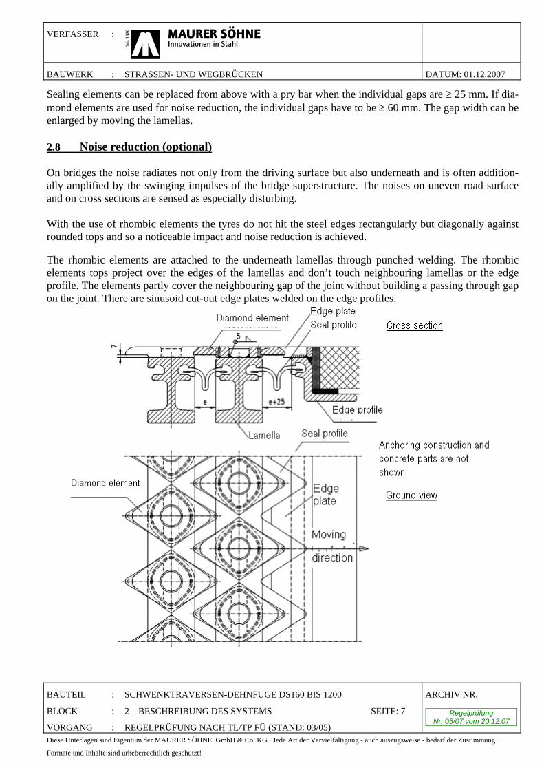
Sealing elements can be replaced from above with a pry bar when the individual gaps are ≥ 25 mm. If dia-mond elements are used for noise reduction, the individual gaps have to be ≥ 60 mm. The gap width can be enlarged by moving the lamellas. 2.8 Noise reduction (optional) On bridges the noise radiates not only from the driving surface but also underneath and is often addition-ally amplified by the swinging impulses of the bridge superstructure. The noises on uneven road surface and on cross sections are sensed as especially disturbing. With the use of rhombic elements the tyres do not hit the steel edges rectangularly but diagonally against rounded tops and so a noticeable impact and noise reduction is achieved. The rhombic elements are attached to the underneath lamellas through punched welding. The rhombic elements tops project over the edges of the lamellas and don’t touch neighbouring lamellas or the edge profile. The elements partly cover the neighbouring gap of the joint without building a passing through gap on the joint. There are sinusoid cut-out edge plates welded on the edge profiles.
VERFASSER :
BAUWERK : STRASSEN- UND WEGBRÜCKEN DATUM: 01.12.2007
BAUTEIL : SCHWENKTRAVERSEN-DEHNFUGE DS160 BIS 1200
BLOCK : 2 – BESCHREIBUNG DES SYSTEMS SEITE: 8
VORGANG : REGELPRÜFUNG NACH TL/TP FÜ (STAND: 03/05)
ARCHIV NR.
Regelprüfung Nr. 05/07 vom 20.12.07
Diese Unterlagen sind Eigentum der MAURER SÖHNE GmbH & Co. KG. Jede Art der Vervielfältigung - auch auszugsweise - bedarf der Zustimmung.
Formate und Inhalte sind urheberrechtlich geschützt!
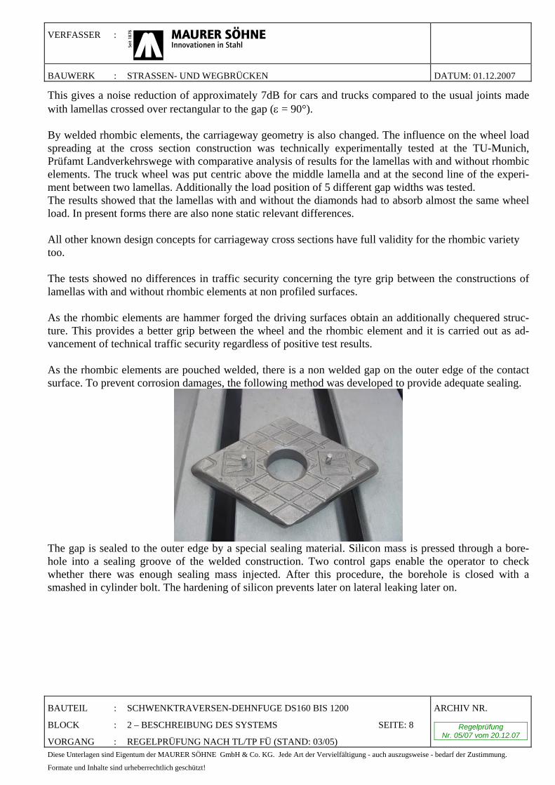
This gives a noise reduction of approximately 7dB for cars and trucks compared to the usual joints made with lamellas crossed over rectangular to the gap (ε = 90°). By welded rhombic elements, the carriageway geometry is also changed. The influence on the wheel load spreading at the cross section construction was technically experimentally tested at the TU-Munich, Prüfamt Landverkehrswege with comparative analysis of results for the lamellas with and without rhombic elements. The truck wheel was put centric above the middle lamella and at the second line of the experi-ment between two lamellas. Additionally the load position of 5 different gap widths was tested. The results showed that the lamellas with and without the diamonds had to absorb almost the same wheel load. In present forms there are also none static relevant differences. All other known design concepts for carriageway cross sections have full validity for the rhombic variety too. The tests showed no differences in traffic security concerning the tyre grip between the constructions of lamellas with and without rhombic elements at non profiled surfaces. As the rhombic elements are hammer forged the driving surfaces obtain an additionally chequered struc-ture. This provides a better grip between the wheel and the rhombic element and it is carried out as ad-vancement of technical traffic security regardless of positive test results. As the rhombic elements are pouched welded, there is a non welded gap on the outer edge of the contact surface. To prevent corrosion damages, the following method was developed to provide adequate sealing.
The gap is sealed to the outer edge by a special sealing material. Silicon mass is pressed through a bore-hole into a sealing groove of the welded construction. Two control gaps enable the operator to check whether there was enough sealing mass injected. After this procedure, the borehole is closed with a smashed in cylinder bolt. The hardening of silicon prevents later on lateral leaking later on.
VERFASSER :
BAUWERK : STRASSEN- UND WEGBRÜCKEN DATUM: 01.12.2007
BAUTEIL : SCHWENKTRAVERSEN-DEHNFUGE DS160 BIS 1200
BLOCK : 3 - HINWEISE FÜR DEN ANWENDER SEITE: 9
VORGANG : REGELPRÜFUNG NACH TL/TP FÜ (STAND: 03/05)
ARCHIV NR.
Regelprüfung Nr. 05/07 vom 20.12.07
Diese Unterlagen sind Eigentum der MAURER SÖHNE GmbH & Co. KG. Jede Art der Vervielfältigung - auch auszugsweise - bedarf der Zustimmung.
Formate und Inhalte sind urheberrechtlich geschützt!
3. Hints for the user
3.1 Checklist for Planning and Control
At the girder planning and inspection respect following points:
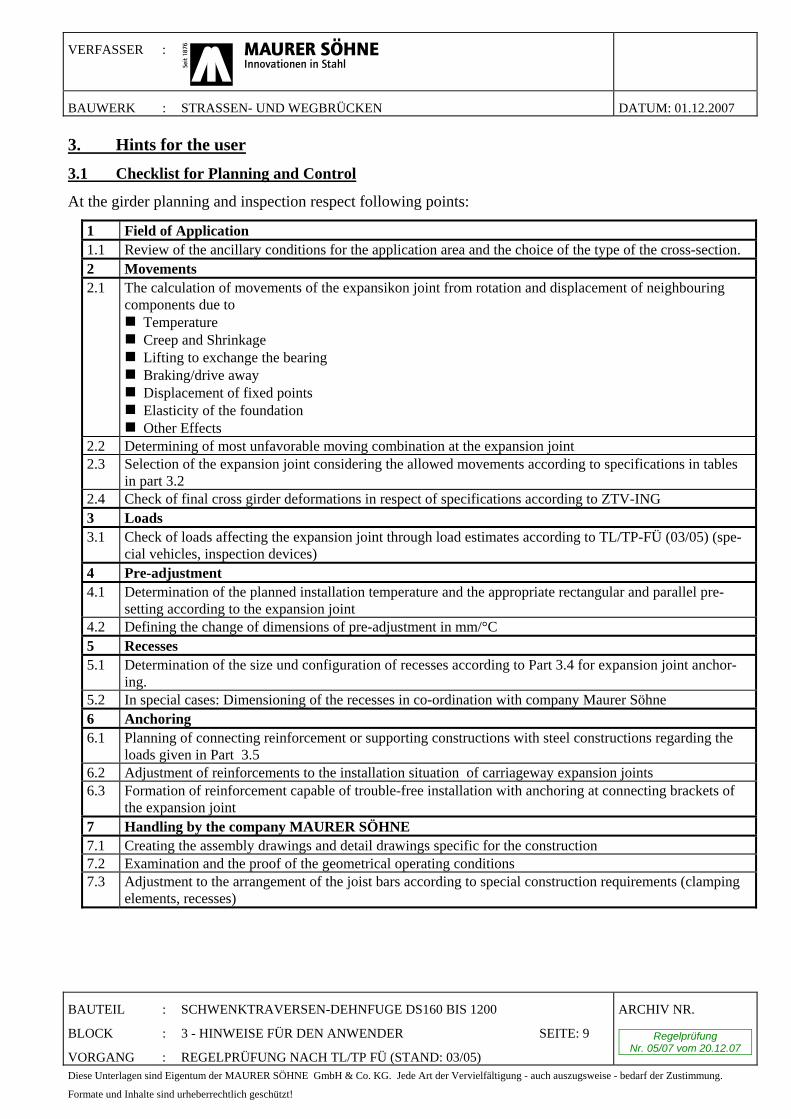
1 Field of Application 1.1 Review of the ancillary conditions for the application area and the choice of the type of the cross-section. 2 Movements 2.1 The calculation of movements of the expansikon joint from rotation and displacement of neighbouring
components due to Temperature Creep and Shrinkage Lifting to exchange the bearing Braking/drive away Displacement of fixed points Elasticity of the foundation Other Effects
2.2 Determining of most unfavorable moving combination at the expansion joint 2.3 Selection of the expansion joint considering the allowed movements according to specifications in tables
in part 3.2 2.4 Check of final cross girder deformations in respect of specifications according to ZTV-ING 3 Loads 3.1 Check of loads affecting the expansion joint through load estimates according to TL/TP-FÜ (03/05) (spe-
cial vehicles, inspection devices) 4 Pre-adjustment 4.1 Determination of the planned installation temperature and the appropriate rectangular and parallel pre-
setting according to the expansion joint 4.2 Defining the change of dimensions of pre-adjustment in mm/°C 5 Recesses 5.1 Determination of the size und configuration of recesses according to Part 3.4 for expansion joint anchor-
ing. 5.2 In special cases: Dimensioning of the recesses in co-ordination with company Maurer Söhne 6 Anchoring 6.1 Planning of connecting reinforcement or supporting constructions with steel constructions regarding the
loads given in Part 3.5 6.2 Adjustment of reinforcements to the installation situation of carriageway expansion joints 6.3 Formation of reinforcement capable of trouble-free installation with anchoring at connecting brackets of
the expansion joint 7 Handling by the company MAURER SÖHNE 7.1 Creating the assembly drawings and detail drawings specific for the construction 7.2 Examination and the proof of the geometrical operating conditions 7.3 Adjustment to the arrangement of the joist bars according to special construction requirements (clamping
elements, recesses)
VERFASSER :
BAUWERK : STRASSEN- UND WEGBRÜCKEN DATUM: 01.12.2007
BAUTEIL : SCHWENKTRAVERSEN-DEHNFUGE DS160 BIS 1200
BLOCK : 3 - HINWEISE FÜR DEN ANWENDER SEITE: 10
VORGANG : REGELPRÜFUNG NACH TL/TP FÜ (STAND: 03/05)
ARCHIV NR.
Regelprüfung Nr. 05/07 vom 20.12.07
Diese Unterlagen sind Eigentum der MAURER SÖHNE GmbH & Co. KG. Jede Art der Vervielfältigung - auch auszugsweise - bedarf der Zustimmung.
Formate und Inhalte sind urheberrechtlich geschützt!
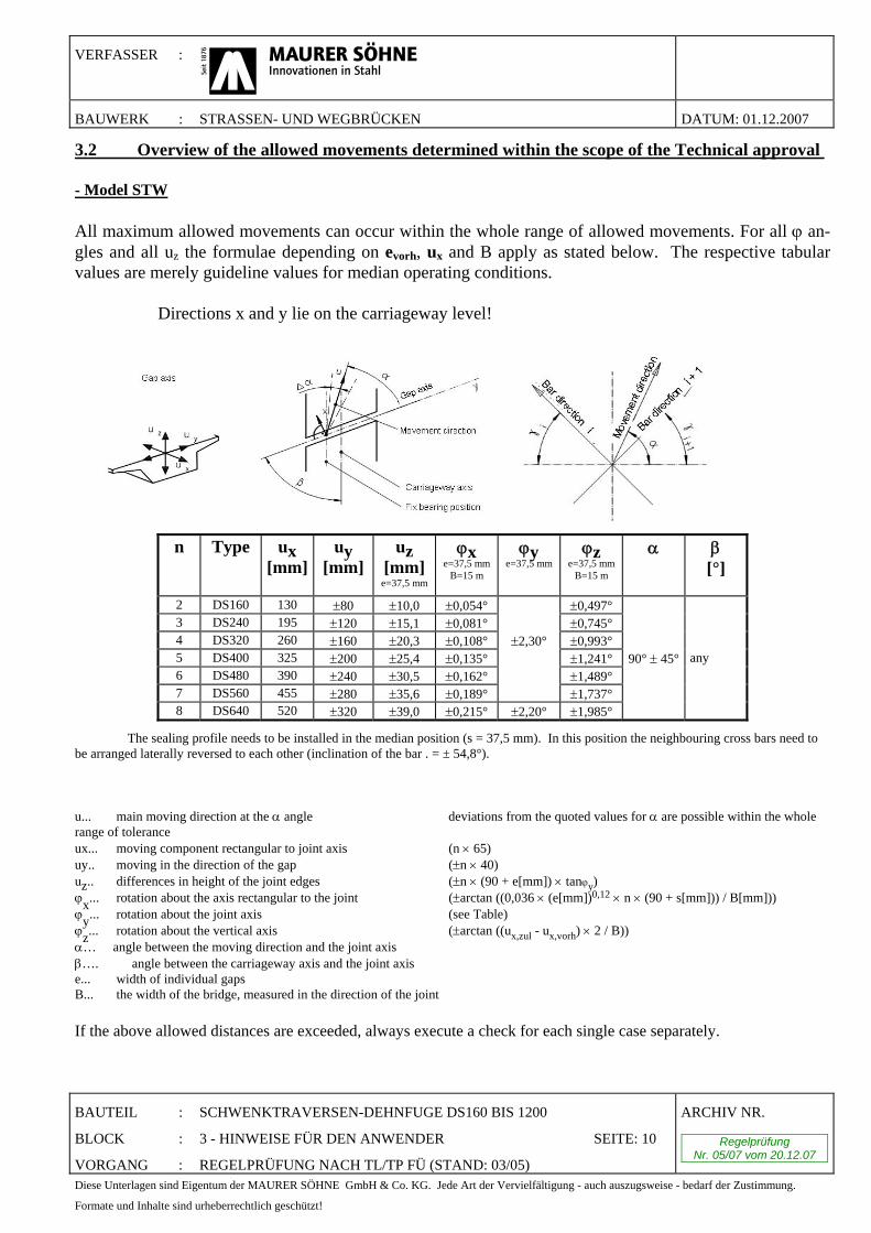
3.2 Overview of the allowed movements determined within the scope of the Technical approval - Model STW All maximum allowed movements can occur within the whole range of allowed movements. For all ϕ an-gles and all uz the formulae depending on evorh, ux and B apply as stated below. The respective tabular values are merely guideline values for median operating conditions. Directions x and y lie on the carriageway level!
n
Type ux [mm]
uy [mm]
uz [mm]
e=37,5 mm
ϕx e=37,5 mm
B=15 m ϕy
e=37,5 mm
ϕz e=37,5 mm
B=15 m α
β [°]
2 DS160 130 ±80 ±10,0 ±0,054° ±0,497° 3 DS240 195 ±120 ±15,1 ±0,081° ±0,745° 4 DS320 260 ±160 ±20,3 ±0,108° ±2,30° ±0,993° 5 DS400 325 ±200 ±25,4 ±0,135° ±1,241° 90° ± 45° any 6 DS480 390 ±240 ±30,5 ±0,162° ±1,489° 7 DS560 455 ±280 ±35,6 ±0,189° ±1,737° 8 DS640 520 ±320 ±39,0 ±0,215° ±2,20° ±1,985°
The sealing profile needs to be installed in the median position (s = 37,5 mm). In this position the neighbouring cross bars need to be arranged laterally reversed to each other (inclination of the bar . = ± 54,8°). u... main moving direction at the α angle deviations from the quoted values for α are possible within the whole range of tolerance ux... moving component rectangular to joint axis (n × 65) uy.. moving in the direction of the gap (±n × 40) uz.. differences in height of the joint edges (±n × (90 + e[mm]) × tanϕy) ϕx... rotation about the axis rectangular to the joint (±arctan ((0,036 × (e[mm])0,12 × n × (90 + s[mm])) / B[mm])) ϕy... rotation about the joint axis (see Table) ϕz... rotation about the vertical axis (±arctan ((ux,zul - ux,vorh) × 2 / B)) α… angle between the moving direction and the joint axis β…. angle between the carriageway axis and the joint axis e... width of individual gaps B... the width of the bridge, measured in the direction of the joint
If the above allowed distances are exceeded, always execute a check for each single case separately.
VERFASSER :
BAUWERK : STRASSEN- UND WEGBRÜCKEN DATUM: 01.12.2007
BAUTEIL : SCHWENKTRAVERSEN-DEHNFUGE DS160 BIS 1200
BLOCK : 3 - HINWEISE FÜR DEN ANWENDER SEITE: 11
VORGANG : REGELPRÜFUNG NACH TL/TP FÜ (STAND: 03/05)
ARCHIV NR.
Regelprüfung Nr. 05/07 vom 20.12.07
Diese Unterlagen sind Eigentum der MAURER SÖHNE GmbH & Co. KG. Jede Art der Vervielfältigung - auch auszugsweise - bedarf der Zustimmung.
Formate und Inhalte sind urheberrechtlich geschützt!
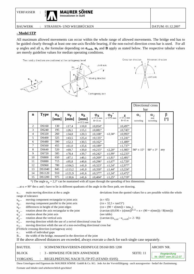
- Model STP
All maximum allowed movements can occur within the whole range of allowed movements. The bridge end has to be guided clearly through at least one one-axis flexible bearing, if the non-swivel direction cross bar is used. For all ϕ angles and all uz the formulae depending on evorh, ux and B apply as stated below. The respective tabular values are merely guideline values for median operating conditions.
Directional cross bar
n
Type ux [mm]
uy [mm]
uz [mm]
e=37,5 mm
ϕx e=37,5 mm
B=15 m ϕy*
e=37,5 mm
z e=37,5 mm
B=15 m α1
swiveling
α2 non
swiveling β
[°]
2 DS160 130 ±17,4 ±10,0 ±0,054° ±0,497° 3 DS240 195 ±26,1 ±15,1 ±0,081° ±0,745° 4 DS320 260 ±34,8 ±20,3 ±0,108° ±2,30° ±0,993° 5 DS400 325 ±43,5 ±25,4 ±0,135° ±1,241° 6 DS480 390 ±52,3 ±30,5 ±0,162° ±1,489° 7 DS560 455 ±61,0 ±35,6 ±0,189° ±1,737° 8 DS640 520 ±69,7 ±39,0 ±0,215° ±2,20° ±1,985° 90° ± 15° 90° ± 3° any 9 DS720 585 ±78,4 ±39,7 ±0,242° ±1,99° ±2,233°
10 DS800 650 ±87,1 ±40,1 ±0,269° ±1,81° ±2,481° 11 DS880 715 ±95,8 ±40,6 ±0,296° ±1,67° ±2,729° 12 DS960 780 ±104,5 ±41,0 ±0,323° ±1,54° ±2,977° 13 DS1040 845 ±113,2 ±41,0 ±0,350° ±1,44° ±3,224° 14 DS1120 910 ±121,9 ±41,6 ±0,377° ±1,34° ±3,472° 15 DS1200 975 ±130,6 ±41,6 ±0,404° ±1,25° ±3,719°
*) The angle ϕy = 2,3° can be mantained with all types through the spreading of box dimensions.
....at α ≠ 90° the α and γ have to lie in different quadrants of the angle in the floor path, see drawing.
u... main moving direction at the α angle deviations from the quoted values for α are possible within the whole range of tolerance ux... moving component rectangular to joint axis (n × 65) uy.. moving component parallel to the joint axis (±n × 32,5 × tan15°) uz.. differences in height of the joint edges (±n × (90 + e[mm]) × tanϕy) ϕx... rotation about the axis rectangular to the joint (±arctan ((0,036 × (s[mm])0,12 × n × (90 + e[mm])) / B[mm])) ϕy... rotation about the joint axis (see table) ϕz... rotation about the vertical axis (±arctan ((ux,zul - ux,vorh) × 2 / B)) α1... moving direction whith the use of a swivel directional cross bar α2... moving direction whith the use of a non-swivelling directional cross bar βVehicle crossing direction (carriageway axix) e... width of individual gaps B... the width of the bridge, measured in the direction of the joint If the above allowed distances are exceeded, always execute a check for each single case separately.
VERFASSER :
BAUWERK : STRASSEN- UND WEGBRÜCKEN DATUM: 01.12.2007
BAUTEIL : SCHWENKTRAVERSEN-DEHNFUGE DS160 BIS 1200
BLOCK : 3 - HINWEISE FÜR DEN ANWENDER SEITE: 12
VORGANG : REGELPRÜFUNG NACH TL/TP FÜ (STAND: 03/05)
ARCHIV NR.
Regelprüfung Nr. 05/07 vom 20.12.07
Diese Unterlagen sind Eigentum der MAURER SÖHNE GmbH & Co. KG. Jede Art der Vervielfältigung - auch auszugsweise - bedarf der Zustimmung.
Formate und Inhalte sind urheberrechtlich geschützt!
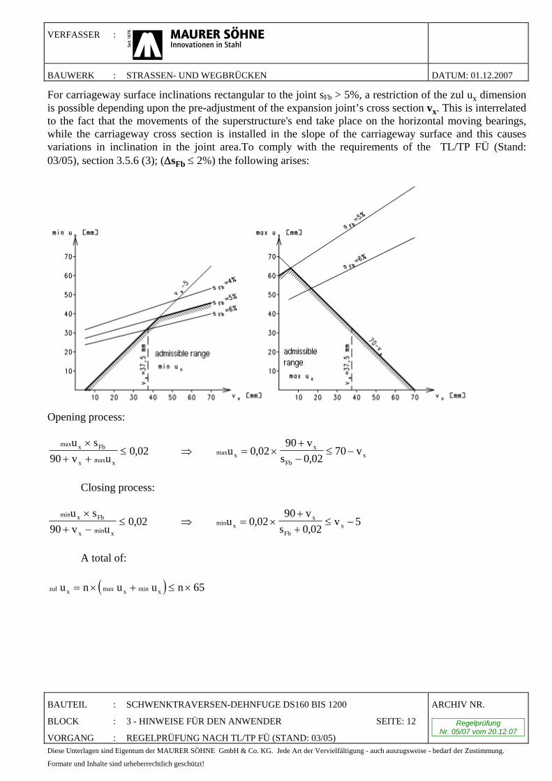
For carriageway surface inclinations rectangular to the joint sFb > 5%, a restriction of the zul ux dimension is possible depending upon the pre-adjustment of the expansion joint’s cross section vx. This is interrelated to the fact that the movements of the superstructure's end take place on the horizontal moving bearings, while the carriageway cross section is installed in the slope of the carriageway surface and this causes variations in inclination in the joint area.To comply with the requirements of the TL/TP FÜ (Stand: 03/05), section 3.5.6 (3); (ΔsFb ≤ 2%) the following arises:
Opening process:
max x Fb
x max x
u s90 v u
×+ +
≤ 0 02, ⇒ max xx
Fbxu
90 vs
v= ×+−
≤ −0 020 02
70,,
Closing process:
min x Fb
x min x
u s90 v u
×+ −
≤ 0 02, ⇒ min xx
Fbxu
90 vs
v= ×++
≤ −0 020 02
5,,
A total of:
( )zul x max x min x u n u u n= × + ≤ × 65
VERFASSER :
BAUWERK : STRASSEN- UND WEGBRÜCKEN DATUM: 01.12.2007
BAUTEIL : SCHWENKTRAVERSEN-DEHNFUGE DS160 BIS 1200
BLOCK : 3 - HINWEISE FÜR DEN ANWENDER SEITE: 13
VORGANG : REGELPRÜFUNG NACH TL/TP FÜ (STAND: 03/05)
ARCHIV NR.
Regelprüfung Nr. 05/07 vom 20.12.07
Diese Unterlagen sind Eigentum der MAURER SÖHNE GmbH & Co. KG. Jede Art der Vervielfältigung - auch auszugsweise - bedarf der Zustimmung.
Formate und Inhalte sind urheberrechtlich geschützt!
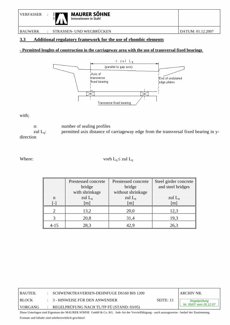
3.3 Additional regulatory framework for the use of rhombic elements - Permitted lenghts of construction in the carriageway area with the use of transversal fixed bearings
with; n: number of sealing profiles zul Lq: permitted axis distance of carriageway edge from the transversal fixed bearing in y-direction Where: vorh Lq ≤ zul Lq
Prestessed concrete bridge
with shrinkage
Prestessed concrete bridge
without shrinkage
Steel girder concrete and steel bridges
n zul Lq zul Lq zul Lq [-] [m] [m] [m]
2 13,2 20,0 12,3 3 20,8 31,4 19,3
4-15 28,3 42,9 26,3
VERFASSER :
BAUWERK : STRASSEN- UND WEGBRÜCKEN DATUM: 01.12.2007
BAUTEIL : SCHWENKTRAVERSEN-DEHNFUGE DS160 BIS 1200
BLOCK : 3 - HINWEISE FÜR DEN ANWENDER SEITE: 14
VORGANG : REGELPRÜFUNG NACH TL/TP FÜ (STAND: 03/05)
ARCHIV NR.
Regelprüfung Nr. 05/07 vom 20.12.07
Diese Unterlagen sind Eigentum der MAURER SÖHNE GmbH & Co. KG. Jede Art der Vervielfältigung - auch auszugsweise - bedarf der Zustimmung.
Formate und Inhalte sind urheberrechtlich geschützt!
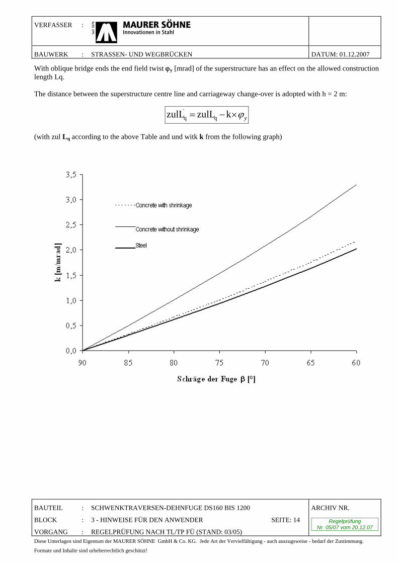
With oblique bridge ends the end field twist ϕy [mrad] of the superstructure has an effect on the allowed construction length Lq. The distance between the superstructure centre line and carriageway change-over is adopted with h = 2 m:
yϕ×−= kzulLzulL q`q
(with zul Lq according to the above Table and und witk k from the following graph)
VERFASSER :
BAUWERK : STRASSEN- UND WEGBRÜCKEN DATUM: 01.12.2007
BAUTEIL : SCHWENKTRAVERSEN-DEHNFUGE DS160 BIS 1200
BLOCK : 3 - HINWEISE FÜR DEN ANWENDER SEITE: 15
VORGANG : REGELPRÜFUNG NACH TL/TP FÜ (STAND: 03/05)
ARCHIV NR.
Regelprüfung Nr. 05/07 vom 20.12.07
Diese Unterlagen sind Eigentum der MAURER SÖHNE GmbH & Co. KG. Jede Art der Vervielfältigung - auch auszugsweise - bedarf der Zustimmung.
Formate und Inhalte sind urheberrechtlich geschützt!
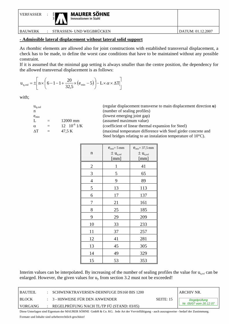
- Admissible lateral displacement without lateral solid support
As rhombic elements are allowed also for joint constructions with established transversal displacement, a check has to be made, to define the worst case conditions that have to be maintained without any possible constraint. If it is assumed that the minimal gap setting is always smaller than the centre position, the dependency for the allowed transversal displacement is as follows:
( ) ⎥⎦
⎤⎢⎣
⎡Δ××−⎟
⎠
⎞⎜⎝
⎛ −×+−−×±= TL5e5,32
20116nu minzulq, α
with; uq,zul (regular displacement transverse to main displacement direction u) n (number of sealing profiles) emin (lowest emerging joint gap) L = 12000 mm (assumed maximum value) α = 12�10-6 1/K (coefficient of linear thermal expansion for Steel) ΔΤ = 47,5 K (maximal temperature difference with Steel girder concrete and Steel bridges relating to an instalation temperature of 10°C).
emin= 5 mm emin= 37,5 mm n ± uq,zul ± uq,zul [mm] [mm]
2 1 41 3 5 65 4 9 89 5 13 113 6 17 137 7 21 161 8 25 185 9 29 209 10 33 233 11 37 257 12 41 281 13 45 305 14 49 329 15 53 353
Interim values can be interpolated. By increasing of the number of sealing profiles the value for uq,zul can be enlarged. However, the given values for uy from section 3.2 must not be exceeded!
VERFASSER :
BAUWERK : STRASSEN- UND WEGBRÜCKEN DATUM: 01.12.2007
BAUTEIL : SCHWENKTRAVERSEN-DEHNFUGE DS160 BIS 1200
BLOCK : 3 - HINWEISE FÜR DEN ANWENDER SEITE: 16
VORGANG : REGELPRÜFUNG NACH TL/TP FÜ (STAND: 03/05)
ARCHIV NR.
Regelprüfung Nr. 05/07 vom 20.12.07
Diese Unterlagen sind Eigentum der MAURER SÖHNE GmbH & Co. KG. Jede Art der Vervielfältigung - auch auszugsweise - bedarf der Zustimmung.
Formate und Inhalte sind urheberrechtlich geschützt!
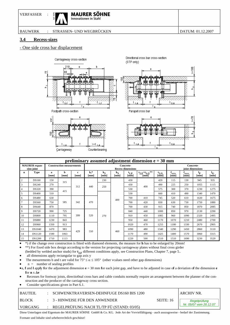
3.4 Recess-sizes
- One side cross bar displacement
preliminary assumed adjustment dimension e = 30 mm MAURER expan-
sion joint Construction measurements Concrete-
Recess dimensions Concrete-
joint dimensions n Type a
[mm] b
[mm] c
[mm] h1*
[mm] h2
[mm] h3
[mm] t1,F
[mm] t2,F=t1,G**
[mm] t2,G [mm]
fmin [mm]
fmax [mm]
lF [mm]
lG [mm]
2 DS160 150 230 430 420 115 130 945 935 3 DS240 270
315 430 490 225 250 1055 1115
4 DS320 390 250
530 575 300 370 1230 1275 5 DS400 510
415
312 440
530
400
660 410 490 1340 1470 6 DS480 630 700 410 745 520 610 1630 1675 7 DS560 750 700 420 830 630 730 1750 1880 8 DS640 870
585 342 470
700 430 915 740 850 1870 2085 9 DS720 990 725 840 440 1000 850 970 2130 2290 10 DS800 1110 795 910 450 1085 960 1090 2320 2495 11 DS880 1230 843
399 520
400
950 460 1170 1070 1210 2480 2700 12 DS960 1350 913 1020 470 1255 1180 1330 2670 2905
13 DS1040 1470 983 1090 480 1340 1290 1450 2860 3110
14 DS1120 1590 1063 1170 490 1425 1400 1570 3060 3315
15 DS1200 1710 1113
429 550
270
460
1220 500 1510 1510 1690 3230 3520
• *) if the change over construction is fitted with diamond elements, the measure for h has to be enlarged by 20mm! • **) For fixed side box design according to the version for projecting carriageway plates without final cross girder (bedded by welded anchor studs) for t2,F different conditions apply, see Construction Plans, Chapter 7, page 5.. • all dimensions apply rectangular to gap axis y • The mesurements b and t are valid for 75° ≤ α ≤ 105° (other vcalues need other gap dimensions) • n = number of sealing profiles •a, f and l apply for the adjustment dimension e = 30 mm for each joint gap, and have to be adjusted in case of a deviation of the dimension e
for n x Δe • Recesses for footway joists, directio0nal cross bars and cable conduits normally require an arrangement between the planner of the con-
struction and the producer of the carriageway cross section. • Consider specifications given in Part 6.1.
VERFASSER :
BAUWERK : STRASSEN- UND WEGBRÜCKEN DATUM: 01.12.2007
BAUTEIL : SCHWENKTRAVERSEN-DEHNFUGE DS160 BIS 1200
BLOCK : 3 - HINWEISE FÜR DEN ANWENDER SEITE: 17
VORGANG : REGELPRÜFUNG NACH TL/TP FÜ (STAND: 03/05)
ARCHIV NR.
Regelprüfung Nr. 05/07 vom 20.12.07
Diese Unterlagen sind Eigentum der MAURER SÖHNE GmbH & Co. KG. Jede Art der Vervielfältigung - auch auszugsweise - bedarf der Zustimmung.
Formate und Inhalte sind urheberrechtlich geschützt!
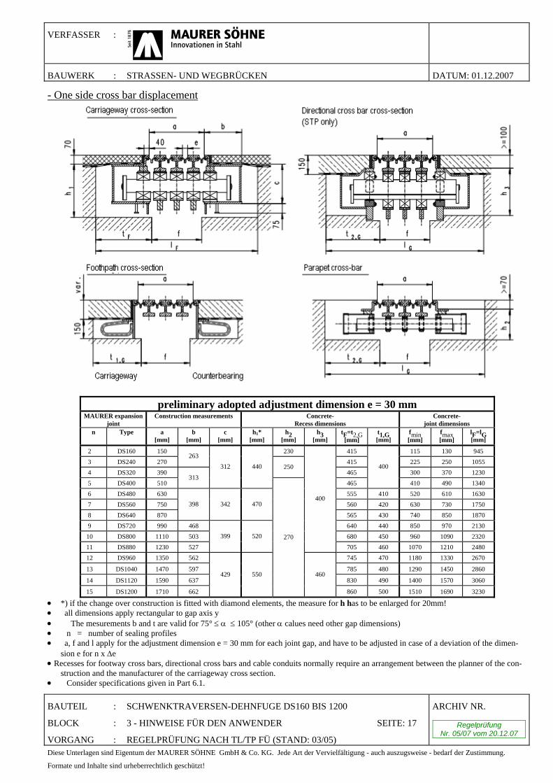
- One side cross bar displacement
preliminary adopted adjustment dimension e = 30 mm MAURER expansion
joint Construction measurements Concrete-
Recess dimensions Concrete-
joint dimensions n Type a
[mm] b
[mm] c
[mm] h1*
[mm] h2
[mm] h3
[mm] tF=t2,G
[mm] t1,G [mm]
fmin [mm]
fmax [mm]
lF=lG [mm]
2 DS160 150 230 415 115 130 945 3 DS240 270
263 415 225 250 1055
4 DS320 390 250
465 300 370 1230 5 DS400 510
313
312 440
465
400
410 490 1340 6 DS480 630 555 410 520 610 1630 7 DS560 750 560 420 630 730 1750 8 DS640 870
398 342 470
565 430 740 850 1870 9 DS720 990 468 640 440 850 970 2130 10 DS800 1110 503 680 450 960 1090 2320 11 DS880 1230 527
399 520
400
705 460 1070 1210 2480 12 DS960 1350 562 745 470 1180 1330 2670
13 DS1040 1470 597 785 480 1290 1450 2860
14 DS1120 1590 637 830 490 1400 1570 3060
15 DS1200 1710 662
429 550
270
460
860 500 1510 1690 3230
• *) if the change over construction is fitted with diamond elements, the measure for h has to be enlarged for 20mm! • all dimensions apply rectangular to gap axis y • The mesurements b and t are valid for 75° ≤ α ≤ 105° (other α calues need other gap dimensions) • n = number of sealing profiles • a, f and l apply for the adjustment dimension e = 30 mm for each joint gap, and have to be adjusted in case of a deviation of the dimen-
sion e for n x Δe • Recesses for footway cross bars, directional cross bars and cable conduits normally require an arrangement between the planner of the con-
struction and the manufacturer of the carriageway cross section. • Consider specifications given in Part 6.1.
VERFASSER :
BAUWERK : STRASSEN- UND WEGBRÜCKEN DATUM: 01.12.2007
BAUTEIL : SCHWENKTRAVERSEN-DEHNFUGE DS160 BIS 1200
BLOCK : 3 - HINWEISE FÜR DEN ANWENDER SEITE: 18
VORGANG : REGELPRÜFUNG NACH TL/TP FÜ (STAND: 03/05)
ARCHIV NR.
Regelprüfung Nr. 05/07 vom 20.12.07
Diese Unterlagen sind Eigentum der MAURER SÖHNE GmbH & Co. KG. Jede Art der Vervielfältigung - auch auszugsweise - bedarf der Zustimmung.
Formate und Inhalte sind urheberrechtlich geschützt!
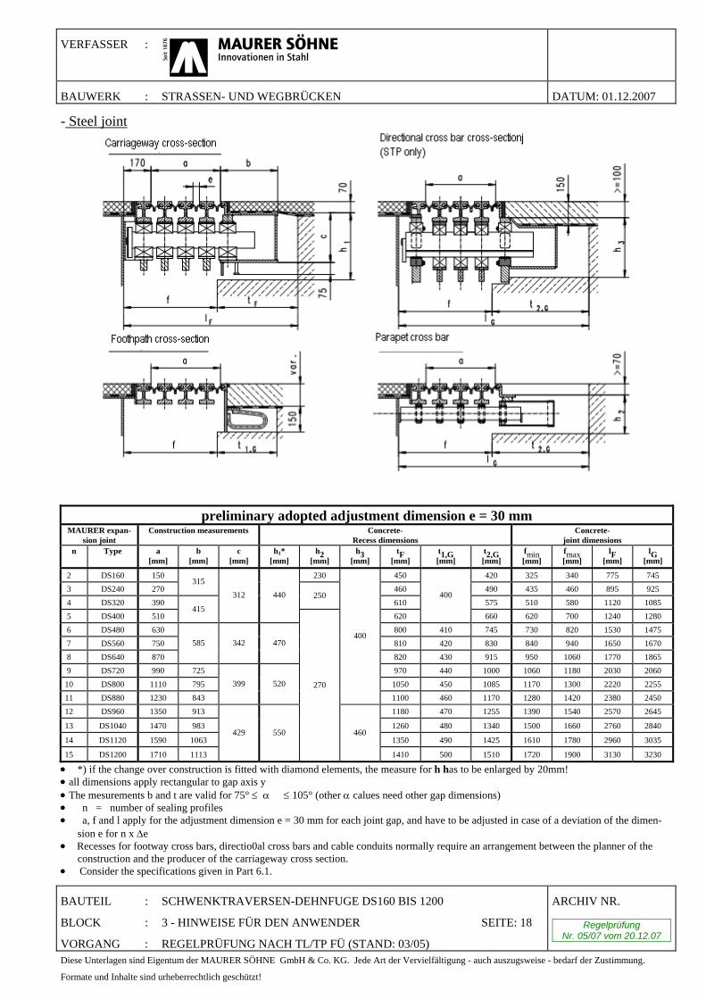
- Steel joint
preliminary adopted adjustment dimension e = 30 mm
MAURER expan-sion joint
Construction measurements Concrete- Recess dimensions
Concrete- joint dimensions
n Type a [mm]
b [mm]
c [mm]
h1* [mm]
h2 [mm]
h3 [mm]
tF [mm]
t1,G [mm]
t2,G [mm]
fmin [mm]
fmax [mm]
lF [mm]
lG [mm]
2 DS160 150 230 450 420 325 340 775 745 3 DS240 270
315 460 490 435 460 895 925
4 DS320 390 250
610 575 510 580 1120 1085 5 DS400 510
415
312 440
620
400
660 620 700 1240 1280 6 DS480 630 800 410 745 730 820 1530 1475 7 DS560 750 810 420 830 840 940 1650 1670 8 DS640 870
585 342 470
820 430 915 950 1060 1770 1865 9 DS720 990 725 970 440 1000 1060 1180 2030 2060 10 DS800 1110 795 1050 450 1085 1170 1300 2220 2255 11 DS880 1230 843
399 520
400
1100 460 1170 1280 1420 2380 2450 12 DS960 1350 913 1180 470 1255 1390 1540 2570 2645
13 DS1040 1470 983 1260 480 1340 1500 1660 2760 2840
14 DS1120 1590 1063 1350 490 1425 1610 1780 2960 3035
15 DS1200 1710 1113
429 550
270
460
1410 500 1510 1720 1900 3130 3230
• *) if the change over construction is fitted with diamond elements, the measure for h has to be enlarged by 20mm! • all dimensions apply rectangular to gap axis y • The mesurements b and t are valid for 75° ≤ α � ≤ 105° (other α calues need other gap dimensions) • n = number of sealing profiles • a, f and l apply for the adjustment dimension e = 30 mm for each joint gap, and have to be adjusted in case of a deviation of the dimen-
sion e for n x Δe • Recesses for footway cross bars, directio0al cross bars and cable conduits normally require an arrangement between the planner of the
construction and the producer of the carriageway cross section. • Consider the specifications given in Part 6.1.
VERFASSER :
BAUWERK : STRASSEN- UND WEGBRÜCKEN DATUM: 01.12.2007
BAUTEIL : SCHWENKTRAVERSEN-DEHNFUGE DS160 BIS 1200
BLOCK : 3 - HINWEISE FÜR DEN ANWENDER SEITE: 19
VORGANG : REGELPRÜFUNG NACH TL/TP FÜ (STAND: 03/05)
ARCHIV NR.
Regelprüfung Nr. 05/07 vom 20.12.07
Diese Unterlagen sind Eigentum der MAURER SÖHNE GmbH & Co. KG. Jede Art der Vervielfältigung - auch auszugsweise - bedarf der Zustimmung.
Formate und Inhalte sind urheberrechtlich geschützt!
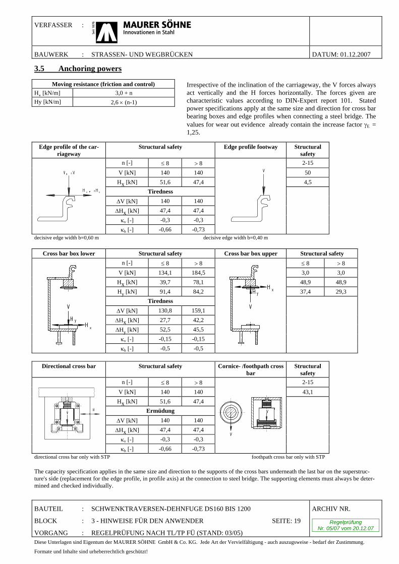
3.5 Anchoring powers
Edge profile of the car-riageway
Structural safety Edge profile footway Structural safety
n [-] ≤ 8 > 8 2-15 V [kN] 140 140 50 Hx [kN] 51,6 47,4 4,5
Tiredness ΔV [kN] 140 140 ΔHx [kN] 47,4 47,4
κv [-] -0,3 -0,3
Δ
Δ
κh [-] -0,66 -0,73
decisive edge width b=0,60 m decisive edge width b=0,40 m
Cross bar box lower Structural safety Cross bar box upper Structural safety n [-] ≤ 8 > 8 ≤ 8 > 8
V [kN] 134,1 184,5 3,0 3,0 Hx [kN] 39,7 78,1 48,9 48,9 Hy [kN] 91,4 84,2 37,4 29,3
Tiredness ΔV [kN] 130,8 159,1 ΔHx [kN] 27,7 42,2 ΔHy [kN] 52,5 45,5
κv [-] -0,15 -0,15
κh [-] -0,5 -0,5
Directional cross bar Structural safety Cornice- /foothpath cross bar
Structural safety
n [-] ≤ 8 > 8 2-15 V [kN] 140 140 43,1 Hx [kN] 51,6 47,4
Ermüdung ΔV [kN] 140 140 ΔHx [kN] 47,4 47,4
κv [-] -0,3 -0,3 κh [-] -0,66 -0,73
directional cross bar only with STP foothpath cross bar only with STP The capacity specification applies in the same size and direction to the supports of the cross bars underneath the last bar on the superstruc-ture's side (replacement for the edge profile, in profile axis) at the connection to steel bridge. The supporting elements must always be deter-mined and checked individually.
Moving resistance (friction and control) Hx [kN/m] 3,0 + n Hy [kN/m] 2,6 × (n-1)
Irrespective of the inclination of the carriageway, the V forces alwaysact vertically and the H forces horizontally. The forces given are characteristic values according to DIN-Expert report 101. Stated power specifications apply at the same size and direction for cross barbearing boxes and edge profiles when connecting a steel bridge. Thevalues for wear out evidence already contain the increase factor γE = 1,25.
VERFASSER :
BAUWERK : STRASSEN- UND WEGBRÜCKEN DATUM: 01.12.2007
BAUTEIL : SCHWENKTRAVERSEN-DEHNFUGE DS160 BIS 1200
BLOCK : 4 - GELTUNGSBEREICH SEITE: 20
VORGANG : REGELPRÜFUNG NACH TL/TP FÜ (STAND: 03/05)
ARCHIV NR.
Regelprüfung Nr. 05/07 vom 20.12.07
Diese Unterlagen sind Eigentum der MAURER SÖHNE GmbH & Co. KG. Jede Art der Vervielfältigung - auch auszugsweise - bedarf der Zustimmung.
Formate und Inhalte sind urheberrechtlich geschützt!
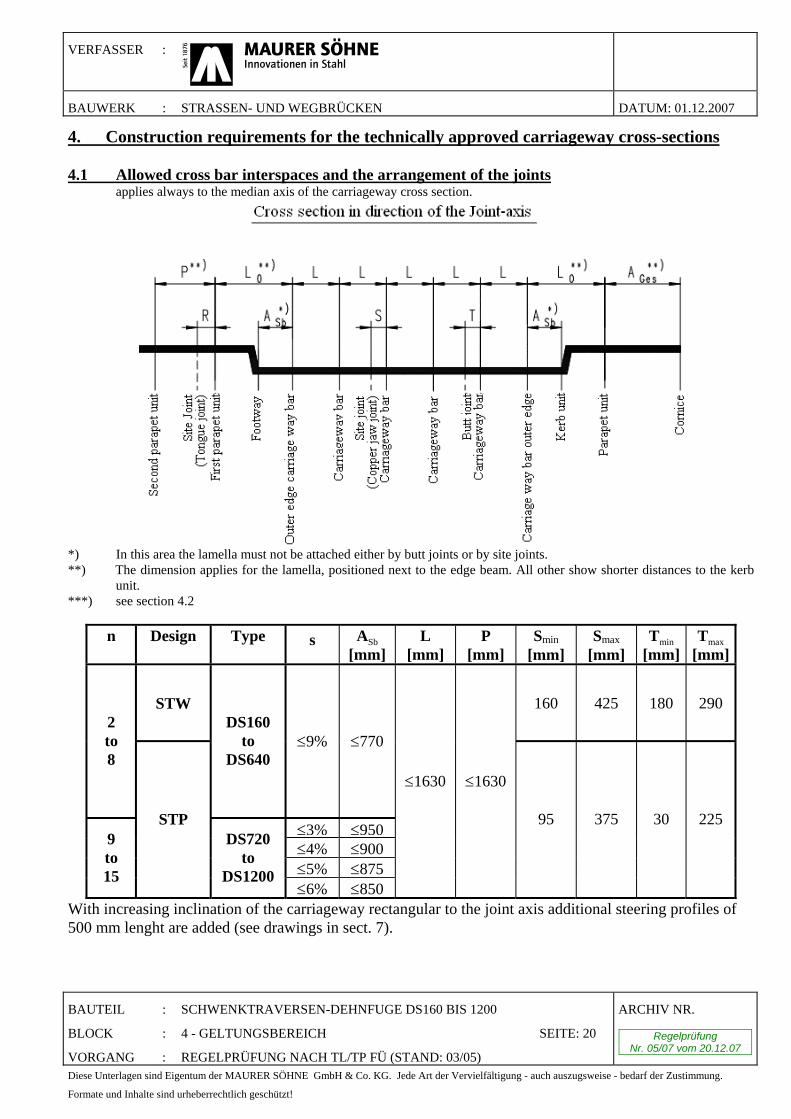
4. Construction requirements for the technically approved carriageway cross-sections 4.1 Allowed cross bar interspaces and the arrangement of the joints
applies always to the median axis of the carriageway cross section.
*) In this area the lamella must not be attached either by butt joints or by site joints. **) The dimension applies for the lamella, positioned next to the edge beam. All other show shorter distances to the kerb
unit. ***) see section 4.2
n Design Type s ASb [mm]
L [mm]
P [mm]
Smin [mm]
Smax [mm]
Tmin [mm]
Tmax [mm]
STW 160 425 180 290 2 to 8
DS160 to
DS640 ≤9% ≤770
≤3% ≤950≤4% ≤900≤5% ≤875
9 to 15
STP DS720
to DS1200
≤6% ≤850
≤1630 ≤1630
95 375 30 225
With increasing inclination of the carriageway rectangular to the joint axis additional steering profiles of 500 mm lenght are added (see drawings in sect. 7).
VERFASSER :
BAUWERK : STRASSEN- UND WEGBRÜCKEN DATUM: 01.12.2007
BAUTEIL : SCHWENKTRAVERSEN-DEHNFUGE DS160 BIS 1200
BLOCK : 4 - GELTUNGSBEREICH SEITE: 21
VORGANG : REGELPRÜFUNG NACH TL/TP FÜ (STAND: 03/05)
ARCHIV NR.
Regelprüfung Nr. 05/07 vom 20.12.07
Diese Unterlagen sind Eigentum der MAURER SÖHNE GmbH & Co. KG. Jede Art der Vervielfältigung - auch auszugsweise - bedarf der Zustimmung.
Formate und Inhalte sind urheberrechtlich geschützt!
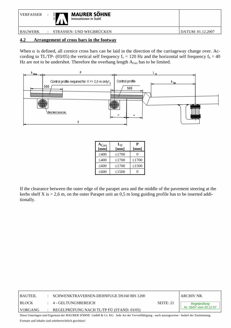
4.2 Arrangement of cross bars in the footway When α is defined, all cornice cross bars can be laid in the direction of the carriageway change over. Ac-cording to TL/TP- (03/05) the vertical self frequency fv = 120 Hz and the horizontal self frequency fh = 40 Hz are not to be undershot. Therefore the overhang length AGes has to be limited.
AGes [mm]
L0 [mm]
P [mm]
≤400 ≤1700 0 ≤400 ≤1700 ≤1700≤600 ≤1700 ≤1500≤600 ≤1500 0
If the clearance between the outer edge of the parapet area and the middle of the pavement steering at the kerbs shelf X is > 2,6 m, on the outer Parapet unit an 0,5 m long guiding profile has to be inserted addi-tionally.
VERFASSER :
BAUWERK : STRASSEN- UND WEGBRÜCKEN DATUM: 01.12.2007
BAUTEIL : SCHWENKTRAVERSEN-DEHNFUGE DS160 BIS 1200
BLOCK : 4 - GELTUNGSBEREICH SEITE: 22
VORGANG : REGELPRÜFUNG NACH TL/TP FÜ (STAND: 03/05)
ARCHIV NR.
Regelprüfung Nr. 05/07 vom 20.12.07
Diese Unterlagen sind Eigentum der MAURER SÖHNE GmbH & Co. KG. Jede Art der Vervielfältigung - auch auszugsweise - bedarf der Zustimmung.
Formate und Inhalte sind urheberrechtlich geschützt!
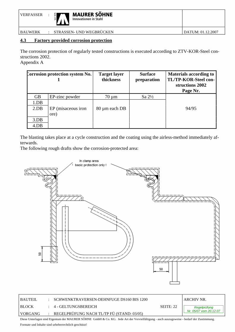
4.3 Factory provided corrosion protection The corrosion protection of regularly tested constructions is executed according to ZTV-KOR-Steel con-structions 2002. Appendix A
Corrosion protection system No. 1
Target layer thickness
Surface preparation
Materials according to TL/TP-KOR-Steel con-
structions 2002 Page Nr.
GB EP-zinc powder 70 µm Sa 2½ 1.DB 2.DB EP (misaceous iron
ore) 80 µm each DB 94/95
3.DB 4.DB
The blasting takes place at a cycle construction and the coating using the airless-method immediately af-terwards. The following rough drafts show the corrosion-protected area:

VERFASSER :
BAUWERK : STRASSEN- UND WEGBRÜCKEN DATUM: 01.12.2007
BAUTEIL : SCHWENKTRAVERSEN-DEHNFUGE DS160 BIS 1200
BLOCK : 5 - EINBAUANWEISUNG SEITE: 23
VORGANG : REGELPRÜFUNG NACH TL/TP FÜ (STAND: 03/05)
ARCHIV NR.
Regelprüfung Nr. 05/07 vom 20.12.07
Diese Unterlagen sind Eigentum der MAURER SÖHNE GmbH & Co. KG. Jede Art der Vervielfältigung - auch auszugsweise - bedarf der Zustimmung.
Formate und Inhalte sind urheberrechtlich geschützt!
5. Installation instructions 5.1 Delivery The expansion joints come delivered to the site in their full length and construction sections respectively and completely assembled. For the transportation, storing and the installation auxiliary constructions have been designed, which ensure that the cross section construction is held in the right installation position and allows an adequate loading. The lifting points for loading and unloading are marked by colour, the loca-tion is labelled, and the total weight of each expansion joint is indicated on separate appendixes or stickers. The joints have to be stored carefully on site i.e. they are to be stored on appropriate grounding (e.g. on square timbers). Damage and contamination must be avoided by means of well ventilated tarpaulins. The following table contains weights per running-meter, which can be used as a guide value for the dimen-sioning of the crane.
Type Weight[kg/m] Type Weight[kg/m] DS160 300 DS720 1040 DS240 380 DS800 1140 DS320 480 DS880 1250 DS400 570 DS960 1390 DS480 690 DS1040 1510 DS560 790 DS1120 1620 DS640 890 DS1200 1740
Table: Weights per running meter for dimensioning of the crane (guiding values) iamond element 5.2 Installation and structural connection in case of concrete structural components Size of the recesses in the structural concrete is to be determined in advance within the scope of the plan-ning of the construction and according to section 3.4 or according to our engineering drawing and later to be realized accordingly. The width of the structural gap, related to the adjustment dimension of the expan-sion joint is always to be considered. Before the beginning of the installation, the recess dimensions are to be checked once again and adjusted if necessary. The surfaces of the recesses as well as the construction joints need to be treated as working gaps.
VERFASSER :
BAUWERK : STRASSEN- UND WEGBRÜCKEN DATUM: 01.12.2007
BAUTEIL : SCHWENKTRAVERSEN-DEHNFUGE DS160 BIS 1200
BLOCK : 5 - EINBAUANWEISUNG SEITE: 24
VORGANG : REGELPRÜFUNG NACH TL/TP FÜ (STAND: 03/05)
ARCHIV NR.
Regelprüfung Nr. 05/07 vom 20.12.07
Diese Unterlagen sind Eigentum der MAURER SÖHNE GmbH & Co. KG. Jede Art der Vervielfältigung - auch auszugsweise - bedarf der Zustimmung.
Formate und Inhalte sind urheberrechtlich geschützt!
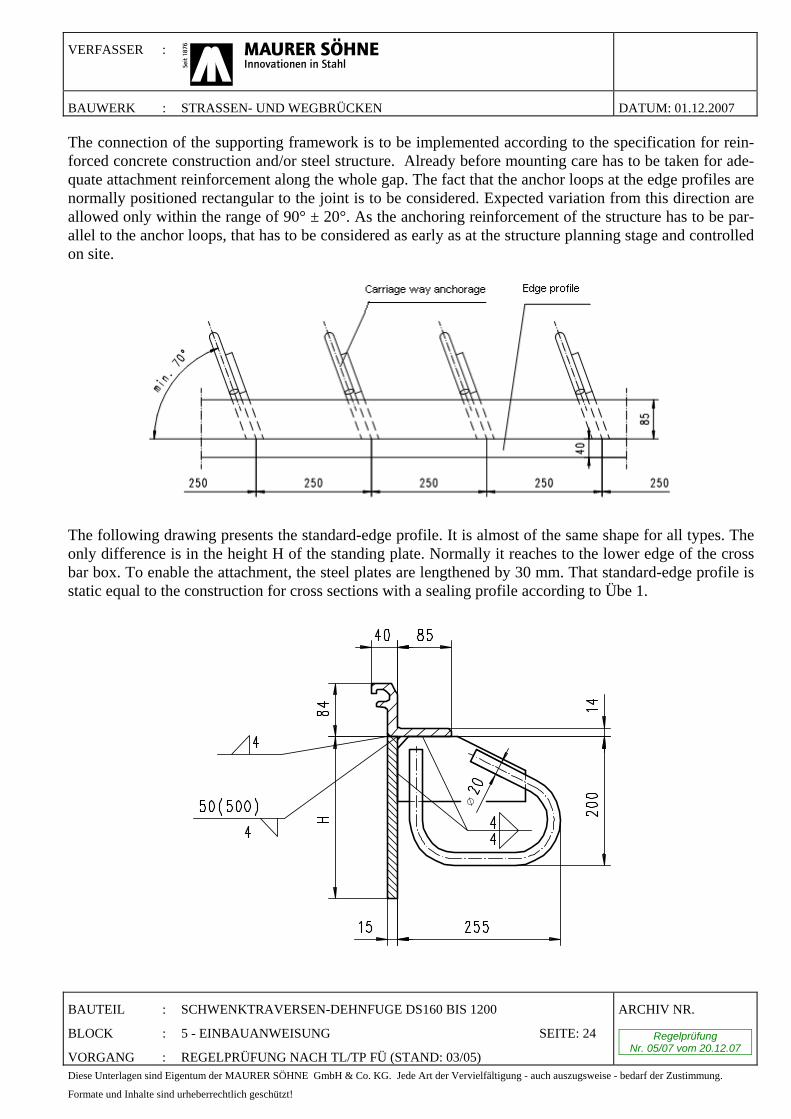
The connection of the supporting framework is to be implemented according to the specification for rein-forced concrete construction and/or steel structure. Already before mounting care has to be taken for ade-quate attachment reinforcement along the whole gap. The fact that the anchor loops at the edge profiles are normally positioned rectangular to the joint is to be considered. Expected variation from this direction are allowed only within the range of 90° ± 20°. As the anchoring reinforcement of the structure has to be par-allel to the anchor loops, that has to be considered as early as at the structure planning stage and controlled on site.
The following drawing presents the standard-edge profile. It is almost of the same shape for all types. The only difference is in the height H of the standing plate. Normally it reaches to the lower edge of the cross bar box. To enable the attachment, the steel plates are lengthened by 30 mm. That standard-edge profile is static equal to the construction for cross sections with a sealing profile according to Übe 1.
∅

VERFASSER :
BAUWERK : STRASSEN- UND WEGBRÜCKEN DATUM: 01.12.2007
BAUTEIL : SCHWENKTRAVERSEN-DEHNFUGE DS160 BIS 1200
BLOCK : 5 - EINBAUANWEISUNG SEITE: 25
VORGANG : REGELPRÜFUNG NACH TL/TP FÜ (STAND: 03/05)
ARCHIV NR.
Regelprüfung Nr. 05/07 vom 20.12.07
Diese Unterlagen sind Eigentum der MAURER SÖHNE GmbH & Co. KG. Jede Art der Vervielfältigung - auch auszugsweise - bedarf der Zustimmung.
Formate und Inhalte sind urheberrechtlich geschützt!
A reinforcement in net or sling form has to be provided underneath the cross box as reinforcement against split drag. See the Construction Plan after Section 7 for appropriate data.
Picture 1: Cross section cross bar box
The construction has to be lifted into the recess by using an adequate truck-mounted crane, then levelled to the required height according to the site engineer and assembled parallel to the longitudinal and transverse slope of the carriageway. The edge profiles have to be aligned carefully along according to the ground plan and to the sheer plan. Specifications of the height position of the cross section relating to the carriageway surface from TL/TP FÜ (Stand: 03/05) have to be regarded. After the carriageway crossover is aligned vertical stiffeners are welded on the sides of the cross bar box as assistant support, and the anchor slings and head bolt dowels of the cross bar box are welded with exist-ing reinforcement. Take care that the welding between the anchor slings and reinforcement first takes place on one side only. On the other side first additional structural steel for horizontal anchoring of head bolt dowels, or at each of the first anchor slings next to the cross bar boxes is added if missing and welded with the site reinforcement, but not with the construction of the cross section. To shorten the period till loosen-ing the installation holder as much as possible, the welding is first done only in the area next to the cross bar boxes then the installations holders are loosened, but not removed, and so additional bending strength is achieved although the possibility of motion is present.
Welding the remaining anchors with the reinforcement fixes the carriageway crossover firmly in its final position. After the attachment to reinforcements, the construction has to bear the appearing structure movements without influence on the later binding process of the concrete.
VERFASSER :
BAUWERK : STRASSEN- UND WEGBRÜCKEN DATUM: 01.12.2007
BAUTEIL : SCHWENKTRAVERSEN-DEHNFUGE DS160 BIS 1200
BLOCK : 5 - EINBAUANWEISUNG SEITE: 26
VORGANG : REGELPRÜFUNG NACH TL/TP FÜ (STAND: 03/05)
ARCHIV NR.
Regelprüfung Nr. 05/07 vom 20.12.07
Diese Unterlagen sind Eigentum der MAURER SÖHNE GmbH & Co. KG. Jede Art der Vervielfältigung - auch auszugsweise - bedarf der Zustimmung.
Formate und Inhalte sind urheberrechtlich geschützt!
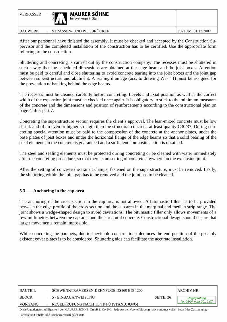
After our personnel have finished the assembly, it must be checked and accepted by the Construction Su-pervisor and the completed installation of the construction has to be certified. Use the appropriate form referring to the construction. Shuttering and concreting is carried out by the construction company. The recesses must be shuttered in such a way that the scheduled dimensions are obtained at the edge beam and the joist boxes. Attention must be paid to careful and close shuttering to avoid concrete tearing into the joist boxes and the joint gap between superstructure and abutment. A sealing drainage (acc. to drawing Was 11) must be assigned for the prevention of banking behind the edge beams. The recesses must be cleaned carefully before concreting. Levels and axial position as well as the correct width of the expansion joint must be checked once again. It is obligatory to stick to the minimum measures of the concrete and the dimensions and position of reinforcements according to the constructional plan on page 4 after part 7. Concreting the superstructure section requires the client’s approval. The lean-mixed concrete must be low shrink and of an even or higher strength then the structural concrete, at least quality C30/37. During con-creting special attention must be paid to the compression of the concrete at the anchor plates, under the base plates of joist boxes and under the horizontal flange of the edge beams so that a solid bearing of the steel elements to the concrete is guaranteed and a sufficient composite action is obtained. The steel and sealing elements must be protected during concreting or be cleaned with water immediately after the concreting procedure, so that there is no setting of concrete anywhere on the expansion joint. After the setting of concrete the transit clamps, fastened on the superstructure, must be removed. Lastly, the shuttering within the joint gap has to be removed and the joint has to be cleaned. 5.3 Anchoring in the cap area The anchoring of the cross section in the cap area is not allowed. A bitumastic filler has to be provided between the edge profile of the cross section and the cap area in the marginal and median strip range. The joint shows a wedge-shaped design to avoid cavitations. The bitumastic filler only allows movements of a few millimetres between the cap area and the structural concrete. Constructional design should ensure that larger movements remain impossible. While concreting the parapets, due to inevitable construction tolerances the end position of the possibly existent cover plates is to be considered. Shuttering aids can facilitate the accurate installation.
VERFASSER :
BAUWERK : STRASSEN- UND WEGBRÜCKEN DATUM: 01.12.2007
BAUTEIL : SCHWENKTRAVERSEN-DEHNFUGE DS160 BIS 1200
BLOCK : 5 - EINBAUANWEISUNG SEITE: 27
VORGANG : REGELPRÜFUNG NACH TL/TP FÜ (STAND: 03/05)
ARCHIV NR.
Regelprüfung Nr. 05/07 vom 20.12.07
Diese Unterlagen sind Eigentum der MAURER SÖHNE GmbH & Co. KG. Jede Art der Vervielfältigung - auch auszugsweise - bedarf der Zustimmung.
Formate und Inhalte sind urheberrechtlich geschützt!
5.4 Procedure for bridges with steel carriageways The working processes are analogue to fastening to concrete components (See chapter 5.2). Basically there are three different methods:
a) Support on a continuous beam, mounted before the end cross girder. b) Support on individual consoles with connection to the end cross girder c) Direct connection of the supporting sides of the joist box to the end cross girder
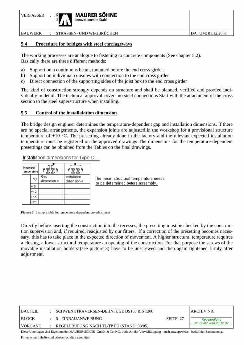
The kind of construction strongly depends on structure and shall be planned, verified and proofed indi-vidually in detail. The technical approval covers no steel connections Start with the attachment of the cross section to the steel superstructure when installing. 5.5 Control of the installalation dimension The bridge design engineer determines the temperature-dependent gap and installation dimensions. If there are no special arrangements, the expansion joints are adjusted in the workshop for a provisional structure temperature of +10 °C. The presetting already done in the factory and the relevant expected installation temperature must be registered on the approved drawings The dimensions for the temperature-dependent presettings can be obtained from the Tables on the final drawings.
Picture 2: Example table for temperature dependent pre-adjustment
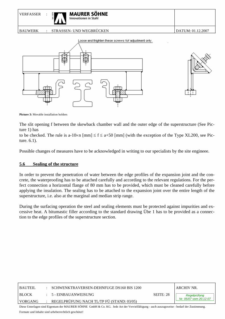
Directly before inserting the construction into the recesses, the presetting must be checked by the construc-tion supervision and, if required, readjusted by our fitters. If a correction of the presetting becomes neces-sary, this has to take place in the expected direction of movement. A higher structural temperature requires a closing, a lower structural temperature an opening of the construction. For that purpose the screws of the movable installation holders (see picture 3) have to be unscrewed and then again tightened firmly after adjustment.
VERFASSER :
BAUWERK : STRASSEN- UND WEGBRÜCKEN DATUM: 01.12.2007
BAUTEIL : SCHWENKTRAVERSEN-DEHNFUGE DS160 BIS 1200
BLOCK : 5 - EINBAUANWEISUNG SEITE: 28
VORGANG : REGELPRÜFUNG NACH TL/TP FÜ (STAND: 03/05)
ARCHIV NR.
Regelprüfung Nr. 05/07 vom 20.12.07
Diese Unterlagen sind Eigentum der MAURER SÖHNE GmbH & Co. KG. Jede Art der Vervielfältigung - auch auszugsweise - bedarf der Zustimmung.
Formate und Inhalte sind urheberrechtlich geschützt!
Picture 3: Movable installation holders
The slit opening f between the skewback chamber wall and the outer edge of the superstructure (See Pic-ture 1) has to be checked. The rule is a-10×n [mm] ≤ f ≤ a+50 [mm] (with the exception of the Type XL200, see Pic-ture. 6.1). Possible changes of measures have to be acknowledged in writing to our specialists by the site engineee.
5.6 Sealing of the structure In order to prevent the penetration of water between the edge profiles of the expansion joint and the con-crete, the waterproofing has to be attached carefully and according to the relevant regulations. For the per-fect connection a horizontal flange of 80 mm has to be provided, which must be cleaned carefully before applying the insulation. The sealing has to be attached to the expansion joint over the entire length of the superstructure, i.e. also at the marginal and median strip range. During the surfacing operation the steel and sealing elements must be protected against impurities and ex-cessive heat. A bitumastic filler according to the standard drawing Übe 1 has to be provided as a connec-tion to the edge profiles of the superstructure section.
VERFASSER :
BAUWERK : STRASSEN- UND WEGBRÜCKEN DATUM: 01.12.2007
BAUTEIL : SCHWENKTRAVERSEN-DEHNFUGE DS160 BIS 1200
BLOCK : 5 - EINBAUANWEISUNG SEITE: 29
VORGANG : REGELPRÜFUNG NACH TL/TP FÜ (STAND: 03/05)
ARCHIV NR.
Regelprüfung Nr. 05/07 vom 20.12.07
Diese Unterlagen sind Eigentum der MAURER SÖHNE GmbH & Co. KG. Jede Art der Vervielfältigung - auch auszugsweise - bedarf der Zustimmung.
Formate und Inhalte sind urheberrechtlich geschützt!
5.7 Further hints Appropriate measures should be taken in order to prevent driving over the cross section before the surfac-ing operation. If there is no possibility of redirecting the site traffic running over the carriageway cross sections, then these need to be protected by bridge-crossings.
If due to the transportation and traffic related reasons site joints are required, the following has to be con-sidered: •Construction of joints according to Chapter 5.8 •Sealing profiles generally are vulcanised (see Chapter 5.12) •The rhombic elements in the connecting area are put in place after the connection of lamellas. If the corrosion protection is damaged due to transport or installation, we recommend a touch up with a single component air humidity hardening coating system:
•Machined grinding of steel parts, standard purity level PMa •If this is not possible or flying rust is present,
20 µm of Stelpant-PU-Repair has to be applied as holding bridge. If grinding was performed, this film must not be applied.
Surface coating system: Priming coating: 1 x 80 µm Stelpant-PU-Zinc Don’t allow greater overlapping with existing coatingarger overlaps with eventually existing coatings are to be omitted! Surface coating: 2 x 80 µm Stelpant-PU-Mica, UV Final coating: 1 x 80 µm Stelpant-PU-Mica, UV (colouring according to plan) The holding bridge, priming coating and surface coating can be applied on the same day. The final coating can be applied 8 hours after the surface coating. For smaller mending jobs the appropriate coating material is to be delivered to the local construction supervisor so the final coating can be applied on the following day. All products are single-component and can be applied using a roller or brush even at air humidity up to 98%. Even at relatively low temperatures (about 0(C) the coatings dry very quickly. Further possibilities for improving the corrosion protection can be obtained from the ZTV-KOR (Steel constructions). After all works are done, the "Übe 2" form as an appendix to the building book according to DIN 1076, as well as the enclosed protocol of the installation are to be filled in and signed. For cross sec-tions, equipped with supervision marks of the external control institute, according to "Übe 2" lines 3 and 4, providing the certificates or test reports according to EN 10204 (DIN 50049) does not apply.
VERFASSER :
BAUWERK : STRASSEN- UND WEGBRÜCKEN DATUM: 01.12.2007
BAUTEIL : SCHWENKTRAVERSEN-DEHNFUGE DS160 BIS 1200
BLOCK : 5 - EINBAUANWEISUNG SEITE: 30
VORGANG : REGELPRÜFUNG NACH TL/TP FÜ (STAND: 03/05)
ARCHIV NR.
Regelprüfung Nr. 05/07 vom 20.12.07
Diese Unterlagen sind Eigentum der MAURER SÖHNE GmbH & Co. KG. Jede Art der Vervielfältigung - auch auszugsweise - bedarf der Zustimmung.
Formate und Inhalte sind urheberrechtlich geschützt!
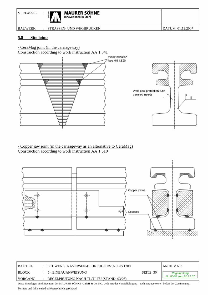
5.8 Site joints - CeraMag joint (in the carriageway) Construction according to work instruction AA 1.541
- Copper jaw joint (in the carriageway as an alternative to CeraMag) Construction according to work instruction AA 1.510
VERFASSER :
BAUWERK : STRASSEN- UND WEGBRÜCKEN DATUM: 01.12.2007
BAUTEIL : SCHWENKTRAVERSEN-DEHNFUGE DS160 BIS 1200
BLOCK : 5 - EINBAUANWEISUNG SEITE: 31
VORGANG : REGELPRÜFUNG NACH TL/TP FÜ (STAND: 03/05)
ARCHIV NR.
Regelprüfung Nr. 05/07 vom 20.12.07
Diese Unterlagen sind Eigentum der MAURER SÖHNE GmbH & Co. KG. Jede Art der Vervielfältigung - auch auszugsweise - bedarf der Zustimmung.
Formate und Inhalte sind urheberrechtlich geschützt!
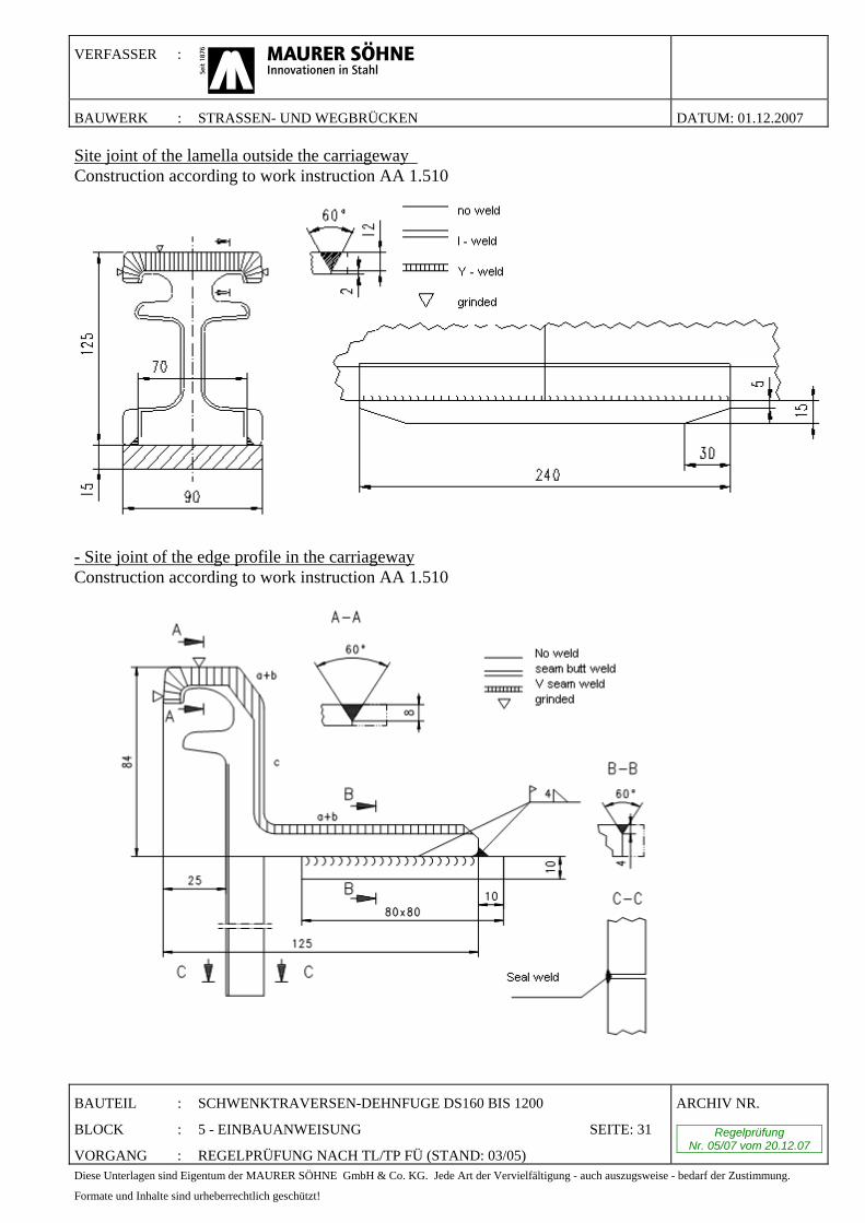
Site joint of the lamella outside the carriageway Construction according to work instruction AA 1.510
- Site joint of the edge profile in the carriageway Construction according to work instruction AA 1.510
VERFASSER :
BAUWERK : STRASSEN- UND WEGBRÜCKEN DATUM: 01.12.2007
BAUTEIL : SCHWENKTRAVERSEN-DEHNFUGE DS160 BIS 1200
BLOCK : 5 - EINBAUANWEISUNG SEITE: 32
VORGANG : REGELPRÜFUNG NACH TL/TP FÜ (STAND: 03/05)
ARCHIV NR.
Regelprüfung Nr. 05/07 vom 20.12.07
Diese Unterlagen sind Eigentum der MAURER SÖHNE GmbH & Co. KG. Jede Art der Vervielfältigung - auch auszugsweise - bedarf der Zustimmung.
Formate und Inhalte sind urheberrechtlich geschützt!
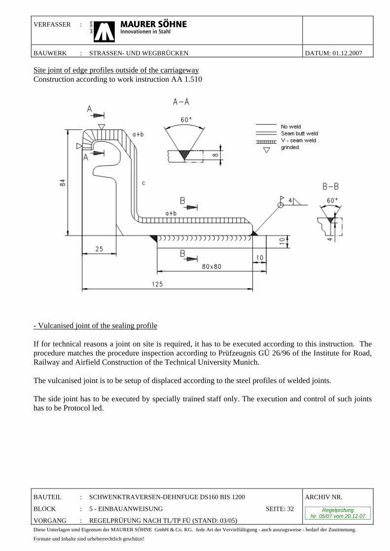
Site joint of edge profiles outside of the carriageway Construction according to work instruction AA 1.510
- Vulcanised joint of the sealing profile If for technical reasons a joint on site is required, it has to be executed according to this instruction. The procedure matches the procedure inspection according to Prüfzeugnis GÜ 26/96 of the Institute for Road, Railway and Airfield Construction of the Technical University Munich. The vulcanised joint is to be setup of displaced according to the steel profiles of welded joints. The side joint has to be executed by specially trained staff only. The execution and control of such joints has to be Protocol led.
VERFASSER :
BAUWERK : STRASSEN- UND WEGBRÜCKEN DATUM: 01.12.2007
BAUTEIL : SCHWENKTRAVERSEN-DEHNFUGE DS160 BIS 1200
BLOCK : 5 - EINBAUANWEISUNG SEITE: 33
VORGANG : REGELPRÜFUNG NACH TL/TP FÜ (STAND: 03/05)
ARCHIV NR.
Regelprüfung Nr. 05/07 vom 20.12.07
Diese Unterlagen sind Eigentum der MAURER SÖHNE GmbH & Co. KG. Jede Art der Vervielfältigung - auch auszugsweise - bedarf der Zustimmung.
Formate und Inhalte sind urheberrechtlich geschützt!
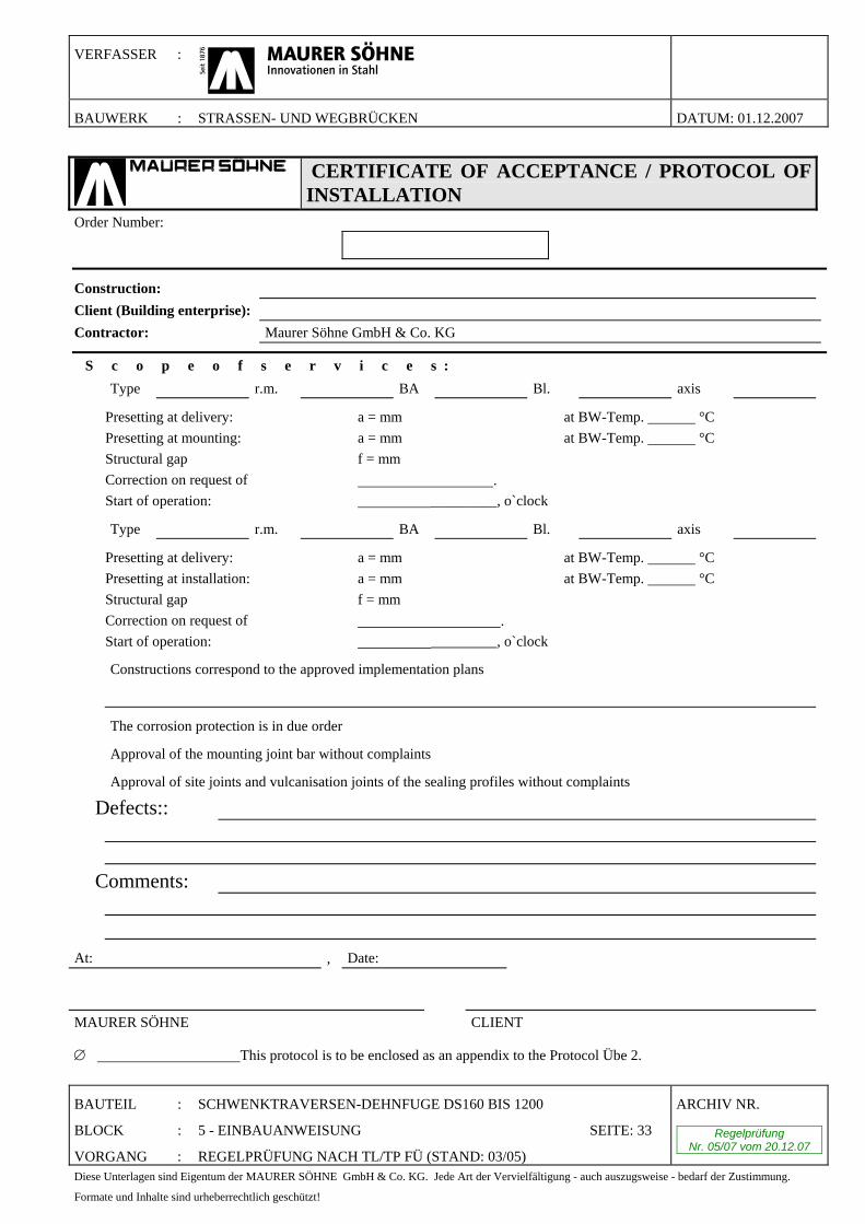
CERTIFICATE OF ACCEPTANCE / PROTOCOL OF INSTALLATION
Order Number:
Construction: Client (Building enterprise): Contractor: Maurer Söhne GmbH & Co. KG
S c o p e o f s e r v i c e s : � Type r.m. BA Bl. axis
Presetting at delivery: a = mm at BW-Temp. °C Presetting at mounting: a = mm at BW-Temp. °C Structural gap f = mm Correction on request of . Start of operation: _________, o`clock
� Type r.m. BA Bl. axis
Presetting at delivery: a = mm at BW-Temp. °C Presetting at installation: a = mm at BW-Temp. °C Structural gap f = mm Correction on request of . Start of operation: _________, o`clock
� Constructions correspond to the approved implementation plans
�
� The corrosion protection is in due order
� Approval of the mounting joint bar without complaints
� Approval of site joints and vulcanisation joints of the sealing profiles without complaints
� Defects::
� Comments:
At: , Date:
MAURER SÖHNE CLIENT ∅ This protocol is to be enclosed as an appendix to the Protocol Übe 2.
VERFASSER :
BAUWERK : STRASSEN- UND WEGBRÜCKEN DATUM: 01.12.2007
BAUTEIL : SCHWENKTRAVERSEN-DEHNFUGE DS160 BIS 1200
BLOCK : 6 – WARTUNG UND ERHALTUNG SEITE: 34
VORGANG : REGELPRÜFUNG NACH TL/TP FÜ (STAND: 03/05)
ARCHIV NR.
Regelprüfung Nr. 05/07 vom 20.12.07
Diese Unterlagen sind Eigentum der MAURER SÖHNE GmbH & Co. KG. Jede Art der Vervielfältigung - auch auszugsweise - bedarf der Zustimmung.
Formate und Inhalte sind urheberrechtlich geschützt!
6. Instructions for maintenance, preservation and exchange of wear and tear parts MAURER-Lamella-expansion joints within the frame of the planned use period are maintenance-free for at least 20 years. But to spot eventually appearing defects on time before greater damage occurs, regular supervision and inspection of the components is appropriate. Periodic and extent are conforming to valid standards i.e.: • DIN 1076 • Product specification sheet for construction supervision for buildings (M-BÜ-K) • Form Übe 2 • Directive for the control, approval and preservation of constructional design and equipment of bridges
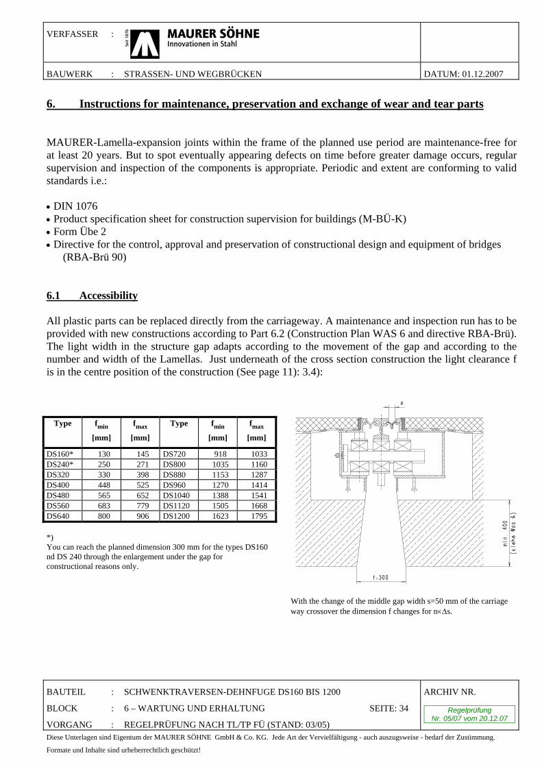
(RBA-Brü 90) 6.1 Accessibility All plastic parts can be replaced directly from the carriageway. A maintenance and inspection run has to be provided with new constructions according to Part 6.2 (Construction Plan WAS 6 and directive RBA-Brü). The light width in the structure gap adapts according to the movement of the gap and according to the number and width of the Lamellas. Just underneath of the cross section construction the light clearance f is in the centre position of the construction (See page 11): 3.4):
Type fmin
[mm]
fmax
[mm]
Type fmin
[mm]
fmax
[mm]
DS160* 130 145 DS720 918 1033 DS240* 250 271 DS800 1035 1160 DS320 330 398 DS880 1153 1287 DS400 448 525 DS960 1270 1414 DS480 565 652 DS1040 1388 1541 DS560 683 779 DS1120 1505 1668 DS640 800 906 DS1200 1623 1795 *) You can reach the planned dimension 300 mm for the types DS160 nd DS 240 through the enlargement under the gap for constructional reasons only.
≥ With the change of the middle gap width s=50 mm of the carriage way crossover the dimension f changes for n×Δs.
VERFASSER :
BAUWERK : STRASSEN- UND WEGBRÜCKEN DATUM: 01.12.2007
BAUTEIL : SCHWENKTRAVERSEN-DEHNFUGE DS160 BIS 1200
BLOCK : 6 – WARTUNG UND ERHALTUNG SEITE: 35
VORGANG : REGELPRÜFUNG NACH TL/TP FÜ (STAND: 03/05)
ARCHIV NR.
Regelprüfung Nr. 05/07 vom 20.12.07
Diese Unterlagen sind Eigentum der MAURER SÖHNE GmbH & Co. KG. Jede Art der Vervielfältigung - auch auszugsweise - bedarf der Zustimmung.
Formate und Inhalte sind urheberrechtlich geschützt!
6.2 Components that must be regularly controlled (1) Sealing profiles
• dirt • ageing • joint connections • damage • secure hold • closeness • regular and sufficient gap widths
(2) Sliding components
• dirt • wearing out • surface damage • proper adjustment • smooth movement • rubbing between individual movable parts
(3) Bearing and spring elements
• correct position • damage • crack free • sufficient prestressing and attachment • remarkable noise production
(4) Corrosion protection
• On driven surfaces the corrosion protection is wearing out in a short time but this is of no meaning. • underneath the sealing profiles • in the footway area • underneath the steel cover plates
VERFASSER :
BAUWERK : STRASSEN- UND WEGBRÜCKEN DATUM: 01.12.2007
BAUTEIL : SCHWENKTRAVERSEN-DEHNFUGE DS160 BIS 1200
BLOCK : 6 – WARTUNG UND ERHALTUNG SEITE: 36
VORGANG : REGELPRÜFUNG NACH TL/TP FÜ (STAND: 03/05)
ARCHIV NR.
Regelprüfung Nr. 05/07 vom 20.12.07
Diese Unterlagen sind Eigentum der MAURER SÖHNE GmbH & Co. KG. Jede Art der Vervielfältigung - auch auszugsweise - bedarf der Zustimmung.
Formate und Inhalte sind urheberrechtlich geschützt!
(5) Steel support construction
• crack free at junctions and firm fit of mechanical joints • welding seams lamella / cross bar (joist) • site and factory butt joints of lamellas • connection of steering construction (cams and stoppers) • anchoring of edge constructions • condition of the concrete underneath the cross bar boxes • free movement of lamellas and cross bars (concrete defects)
(6) Coating joint
• condition of the pouring gap between the edge profile and the coating • deformation of the edge profile in the carriageway • deformation of the edge profile at the cap • oating damages • rut building • height evenness of gap edges • coating bank
(7) Steel cover plates in the sidewalks and the parapet area
• corrosion • screw connection • noise production • constraints • correct position
The control results have to be Protocol led. 6.3 Replacing the sealing profiles The replacement or damage free installation and removal of sealing elements is possible from above at single gap widths ≥ 25 mm. If the joint is equipped with rhombic elements, the single gap widths have to be ≥ 60 mm. For that the lamellas have eventually to be displaced rectangular to the gap.
• opening of the gap slit with a hoist • dismounting the old sealing profile using special fitting-levers • control of corrosion-grade of the steel claws • check and renewal of corrosion protection (if necessary) • eventual vulcanizing of the joint between the remaining and new sealing profile • paraffin oil greasing of the steel claws • interlacing new sealing profiles using a pecial-fitting lever • right position control
VERFASSER :
BAUWERK : STRASSEN- UND WEGBRÜCKEN DATUM: 01.12.2007
BAUTEIL : SCHWENKTRAVERSEN-DEHNFUGE DS160 BIS 1200
BLOCK : 6 – WARTUNG UND ERHALTUNG SEITE: 37
VORGANG : REGELPRÜFUNG NACH TL/TP FÜ (STAND: 03/05)
ARCHIV NR.
Regelprüfung Nr. 05/07 vom 20.12.07
Diese Unterlagen sind Eigentum der MAURER SÖHNE GmbH & Co. KG. Jede Art der Vervielfältigung - auch auszugsweise - bedarf der Zustimmung.
Formate und Inhalte sind urheberrechtlich geschützt!
6.4 Replacing the wear parts
(1) sliding bearings and springs (from carriageway)
•Removal of sliding bearings
Remove welds of some rhombic elements by drilling.
Dismount the sealing profiles in the bearing holder area.
Ererect the lifting gear.
Hoist the lamella with the lifting gear (slide spring is compressed) at the bearing holders.
Enlarge the gap between lamellas using hydraulic moulding presses to approximately 80 mm.
ismount the slide bearing.
•Removal and installation of sliding springs
Remodel the lifting gear after dismantling the slide bearing.
Press down the lamella with a hydraulic press (slide spring is set free).
Dismount the slide spring.
Install a new sliding spring.
•Sliding bearing installation
Remodel the lifting gear.
Hoist the lamella with the lifting gear.
Install the slide bearing.
Take the lifting gear appart.
Set the gap between lamellas.
Install the sealing profile.

VERFASSER :
BAUWERK : STRASSEN- UND WEGBRÜCKEN DATUM: 01.12.2007
BAUTEIL : SCHWENKTRAVERSEN-DEHNFUGE DS160 BIS 1200
BLOCK : 6 – WARTUNG UND ERHALTUNG SEITE: 38
VORGANG : REGELPRÜFUNG NACH TL/TP FÜ (STAND: 03/05)
ARCHIV NR.
Regelprüfung Nr. 05/07 vom 20.12.07
Diese Unterlagen sind Eigentum der MAURER SÖHNE GmbH & Co. KG. Jede Art der Vervielfältigung - auch auszugsweise - bedarf der Zustimmung.
Formate und Inhalte sind urheberrechtlich geschützt!
(2) Slide bearing and spring from below
•Removal of sliding bearings
Arrange the removal equipment.
Lift the bearing holder together with the lamella with the hydraulic press (slide spring is pressed).
Dismount the sliding bearings
•Removal and installation of slide springs
Rearrange the lifting gear.
With hydraulic gear press down the lamella at bearing holders (slide spring is set free).
Dismount the slide spring.
Mount a new sliding spring.
•Slide bearing installation
Arrange the dismantling equipment.
Lift the bearing holder together with the lamella with the hydraulic press (glide spring is pressed).
Mount new slide bearing.
(3) Lamella
With the use of open holders the lamella can be dismantled without damage. For that the car-riageway and guiding bars have to be aligned at least within each construction section. For parapet units the guiding lugs have to be ripped half aside and welded back after the procedure. •Dismantling of sealing profiles, slide bearings and springs. •Lateral displacement by 150 mm and lifting of the lamella. •Installation of new parts.
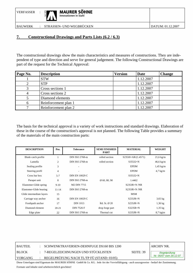
VERFASSER :
BAUWERK : STRASSEN- UND WEGBRÜCKEN DATUM: 01.12.2007
BAUTEIL : SCHWENKTRAVERSEN-DEHNFUGE DS160 BIS 1200
BLOCK : 7-REGELZEICHNUNGEN UND STÜCKLISTEN SEITE: 39
VORGANG : REGELPRÜFUNG NACH TL/TP FÜ (STAND: 03/05)
ARCHIV NR.
Regelprüfung Nr. 05/07 vom 20.12.07
Diese Unterlagen sind Eigentum der MAURER SÖHNE GmbH & Co. KG. Jede Art der Vervielfältigung - auch auszugsweise - bedarf der Zustimmung.
Formate und Inhalte sind urheberrechtlich geschützt!
7. Constructional Drawings and Parts Lists (6.2 / 6.3) The constructional drawings show the main characteristics and measures of constructions. They are inde-pendent of type and direction and serve for general judgement. The following Constructional Drawings are part of the request for the Technical Approval: Page No. Description Version Date Change
1 STW 1.12.2007 2 STP 1.12.2007 3 Cross sections 1 1.12.2007 4 Cross sections 2 1.12.2007 5 Diamond elements 1.12.2007 6 Reinforcement plan 1 1.12.2007 7 Reinforcement plan 2 1.12.2007
The basis for the technical approval is a variety of work instructions and standard drawings. Elaboration of these in the course of the construction's approval is not planned. The following Table provides a summary of the materials of the main construction parts:
DESCRIPTION Pos. Tolerance SEMI FINISHED PART
MATERIAL WEIGHT
Blade catch profile 1 DIN ISO 2768-m rolled section S235J0+AR/(1.4571) 21,6 kg/m
Lamella 2 DIN ISO 2768-m rolled section S355J2+N 46,6 kg/m
Sealing profile 3 - EPDM 1,45 kg/m
Steering profil 4 - EPDM 4,7 kg/m
Cross bar box 5-7 DIN EN 10029 C S355J2+N
Parapet unit 8 DIN ISO 2768-m Ø 60, 80, 90 1.4462
Elastomer-Glide spring 9-10 M2 DIN 7715 S235JR+N /NR
Elastomer-Glide bearing 11-14 DIN ISO 2768-m S235JR+N /NR
Glide intermediate layers 15 MSM
Carriage way anchor 16 DIN EN 10029 C S235JR+N 3,65 kg
Foothpath anchor 17 DIN 1013 Rd. St. Ø 20 S235JR+N 1,36 kg
Diamond element 20-21 DIN 7526 F drop forge part S3235R+N 1,35 kg
Edge plate 22 DIN ISO 2768-m Thermal cut S235JR+N 8,7 kg(m
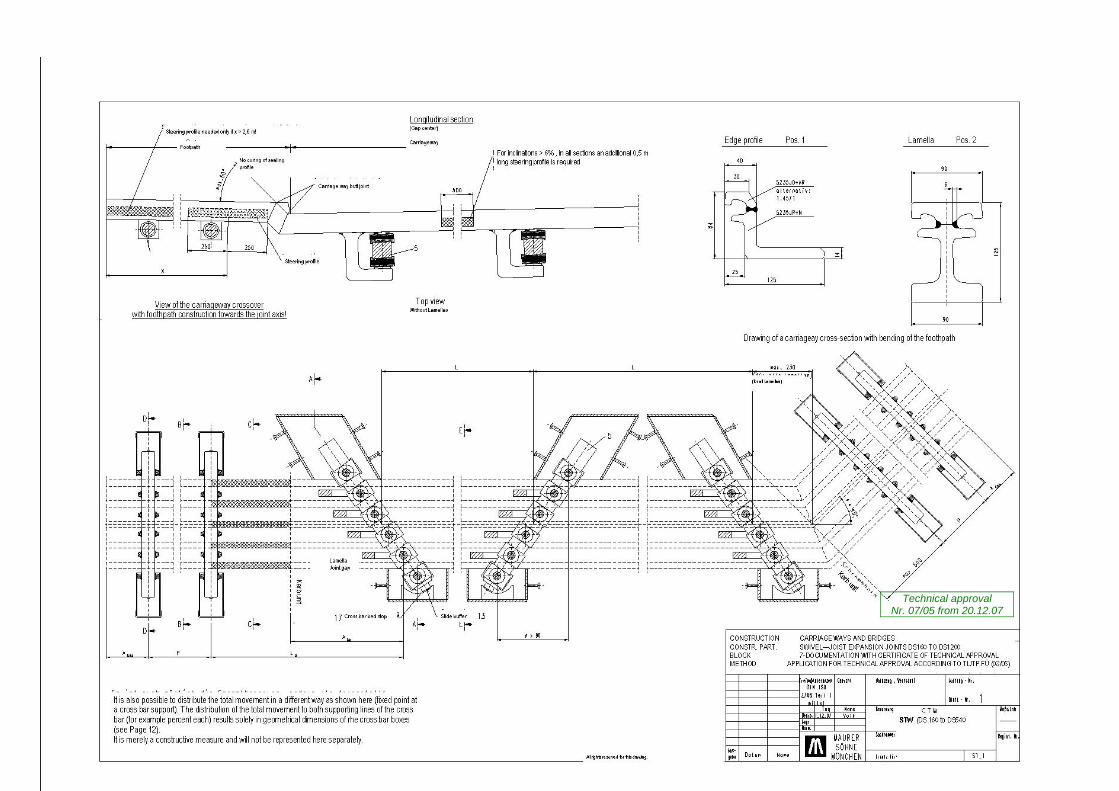
Technical approval Nr. 07/05 from 20.12.07
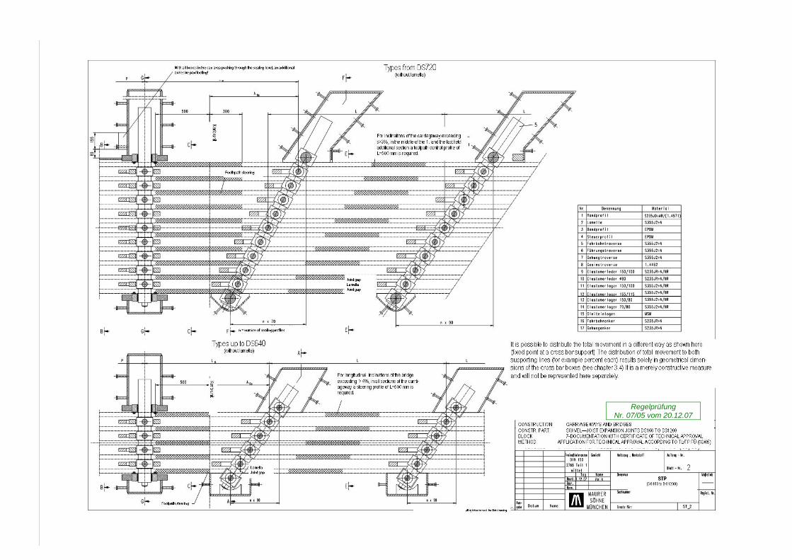
Regelprüfung Nr. 07/05 vom 20.12.07
Regelprüfung Nr. 05/07 vom 20.12.07
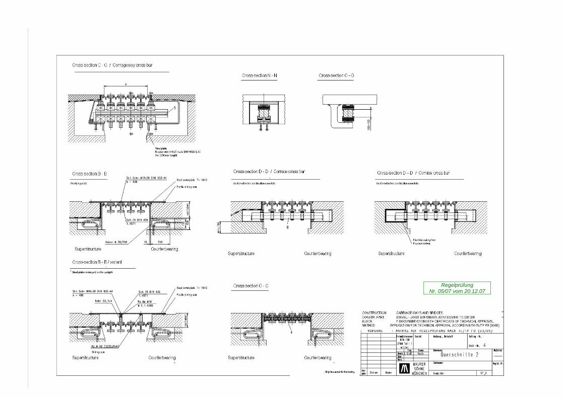
Regelprüfung Nr. 05/07 vom 20.12.07
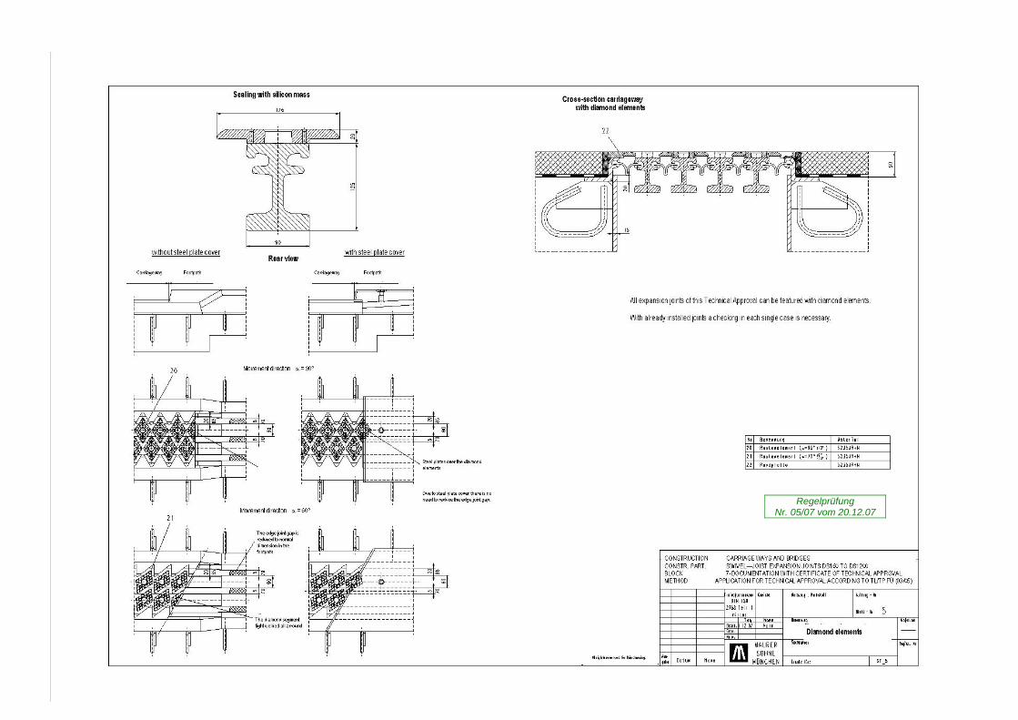
Regelprüfung Nr. 05/07 vom 20.12.07
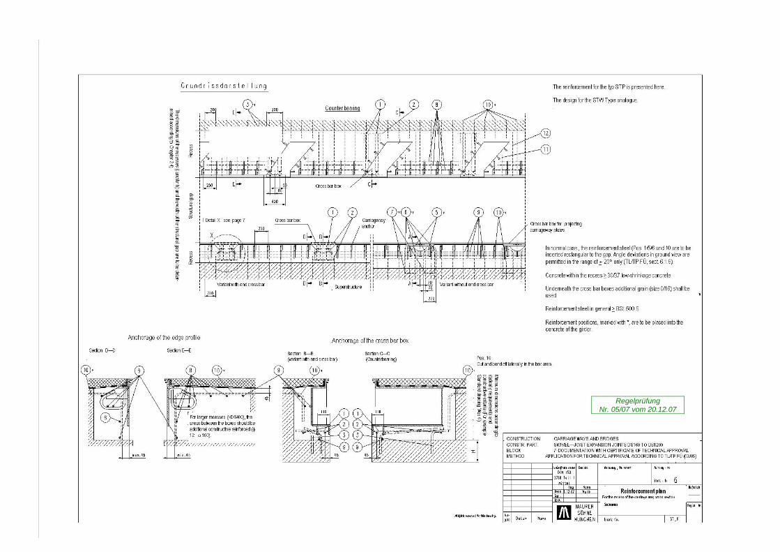
Regelprüfung Nr. 05/07 vom 20.12.07
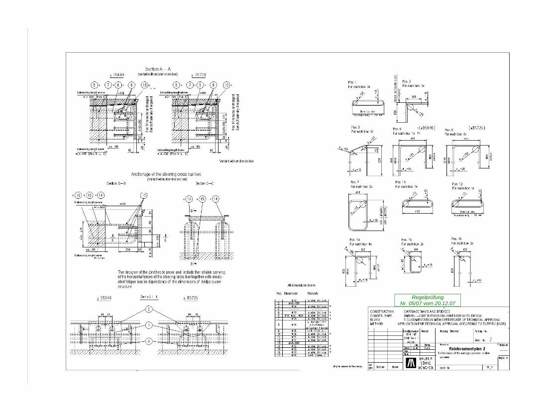
Regelprüfung Nr. 05/07 vom 20.12.07