TECH REPORT #2 - Pennsylvania State University · step down transformer for its branch panels on...
26
Tech Report #2 New Jersey Center for Science, Technology, and Mathematics Education Page 1 TECH REPORT #2 JOHN P. MULHERN NOVEMBER 4. 2008
Transcript of TECH REPORT #2 - Pennsylvania State University · step down transformer for its branch panels on...

Tech Report #2
New Jersey Center for Science, Technology, and Mathematics Education
Page 1
TECH REPORT #2
JOHN P. MULHERN
NOVEMBER 4. 2008

Tech Report #2
New Jersey Center for Science, Technology, and Mathematics Education
Page 2
TABLE OF CONTENTS _______________________________________________
I. POWER DISTRIBUTION SYSTEMS
3.………………A‐a) DRAWINGS USED FOR SINGLE LINE DIAGRAM 4.………………A‐b1) 11”x17” SINGLE LINE DIAGRAM (NORMAL POWER) 5.………………A‐b2) 11”x17” SINGLE LINE DIAGRAM (EMERGENCY POWER) 6.………………A‐b3) 11”x17” RISER DIAGRAM (NORMAL POWER) 7.………………A‐b4) 11”x17” RISER DIAGRAM (EMERGENCY POWER) 8.………………B‐a) EXECUTIVE SUMMARY 9.………………B‐b) SUMMARY DESCRIPTION OF POWER SYSTEM 9….…………...B‐c) UTLILITY COMPANY INFORMATION 9‐10.………...B‐d) SERVICE ENTRANCE 10..…………...B‐e) VOLTAGE SYSTEMS 10‐11.….……B‐c) EMERGENCY POWER SYSTEMS 11‐14....….…B‐g) LOCATIONS OF SWITCHGEAR AND ELEC. CLOSETS 15.…………….B‐h) OVERCURRENT DEVICES 15‐16..………B‐i) TRANSFORMERS 17.…………….B‐j) SPECIAL SYSTEMS 17‐18.……….B‐k) LIGHTING LOADS 19‐21….…….B‐l) MECHANNICAL AND OTHER LOADS 22‐24….…….B‐m) SERVICE ENTRANCE SIZE 25.…………….B‐n) ENVIRONMENTAL STEWARDSHIP DESIGN 25.…………….B‐o) DESIGN ISSUES
II. COMMUNICATION SYSTEMS
26.……………B‐a) COMMUNICATION SYSTEMS SUMMARY DESCRIPTION
II. APPENDIX 27.……………C‐a) FEEDER SCHEDULE 28‐30..……. C‐c) 50W, 150W, & 175W MH MAGNETIC BALLAST CUTSHEETS 31.……………C‐b1) 36”x48” SINGLE LINE DIAGRAM (NORMAL POWER) 32.……………C‐b2) 36”x48” SINGLE LINE DIAGRAM (EMERGENCY POWER) 33.……………C‐b3) 36”x48” RISER DIAGRAM (NORMAL POWER) 34.……………C‐b4) 36”x48” RISER DIAGRAM (EMERGENCY POWER)

Tech Report #2
New Jersey Center for Science, Technology, and Mathematics Education
Page 3
I. POWER DISTRIBUTION SYSTEMS
_______________________________________________
A-a.) DRAWINGS USED FOR SINGLE LINE DIAGRAM
E701 – NORMAL POWER RISER DIAGRAM
E702 – EMERGENCY POWER RISER DIAGRAM

Tech Report #2
New Jersey Center for Science, Technology, and Mathematics Education
Page 4
I. POWER DISTRIBUTION SYSTEMS _______________________________________________
A-b1.) SINGLE LINE DIAGRAM 11”x17”(Normal Power) The normal power single line diagram will be provided instead of this page in the future.

Tech Report #2
New Jersey Center for Science, Technology, and Mathematics Education
Page 5
I. POWER DISTRIBUTION SYSTEMS _______________________________________________
A-b2.) SINGLE LINE DIAGRAM 11”x17”(Emergency Power) The emergency power single line diagram will be provided instead of this page in the future.

Tech Report #2
New Jersey Center for Science, Technology, and Mathematics Education
Page 6
I. POWER DISTRIBUTION SYSTEMS _______________________________________________
A-b3.) ORIGINAL NORMAL POWER RISER 11”x17” (E701) The emergency power single line diagram will be provided instead of this page in the future.
Tech Report #2
New Jersey Center for Science, Technology, and Mathematics Education
Page 7
I. POWER DISTRIBUTION SYSTEMS _______________________________________________
A-b4.) ORIGINAL EMERGENCY POWER RISER (E702) The emergency power single line diagram will be provided instead of this page in the future.

Tech Report #2
New Jersey Center for Science, Technology, and Mathematics Education
Page 8
I. POWER DISTRIBUTION SYSTEMS _______________________________________________ B-a.) EXECUTIVE SUMMARY Technical Report #2 is an analysis of the designed electrical system for the New Jersey Center
for Science, Technology, and Mathematics Building. Addendum #4 of the construction documents was
used to determine most of the information for this building. This project was designed by Cannon
Design, Inc. for Kean University in Northern New Jersey. The NEC 2008 Handbook was the code book
referenced for this report. For electricity rates, the website of PSE&G was referenced.
Many aspects of this building’s electrical systems are described in detail. The methods of
distribution for both normal and emergency distribution are explained. There are tables for
transformers, panelboards, and other equipment scattered throughout the building. The properties of
these components and their locations on the drawings are included in the tables.
The original diagram by Cannon Design, Inc. was a riser type. This was redrawn into a single
line diagram for ease of use. Every individual feeder was tagged with its own call number. There is a
feeder schedule for these tags listing the feeder sizes and other various properties.
The service was sized utilizing three methods. For the conceptual stage, the load per square foot
method was used. This is a very rough estimate and usually proves to be higher than the actual loads.
The next method was also a load per square foot, but it was separated by components of the building
such as the HVAC load per square foot. This brings the service size closer to the optimum value. The
final method is calculating the actual load in the building. Due to time constraints, the actual receptacle
and lighting loads were not calculated. The loads determined from the schematic phase were used.
Demand factors were applied for the respective loads.

Tech Report #2
New Jersey Center for Science, Technology, and Mathematics Education
Page 9
I. POWER DISTRIBUTION SYSTEMS _______________________________________________
B-b.) SUMMARY DESCRIPTION OF POWER SYSTEM
Public Service Electric and Gas Company (PSE&G) provides electrical service for this
NJCSTME building from a utility pole on Kean Drive. The primary service runs underground in a duct bank to the outdoor pad mounted primary switch gear and PSE&G meter. The primary is at 13.2 KV and is stepped down at a 3333 KVA transformer to a 480Y/277V system. The main transformer is owned by Kean University. On the 1st floor this transformer feeds distribution panel boards on the first and second floors, from which branch panels are fed. The normal power branch is distributed by a 1200A bus duct and 480Y/277V system from the 3rd through 6th floor. There are transformers for each floor which step down the voltage to 208Y/120V, and the secondary leads to a distribution panel. These distribution panels provide power to the multiple laboratory panels on each floor.
For emergency there is a packaged diesel generator set with weatherproof and sound attenuating enclosure and sub-base day tank. It is rated at 500 kW and at 0.8 power factor. There is an emergency, standby, and optional standby branch. These branches are in separate electrical rooms from the normal on each floor.
There are four automatic transfer switches in the Emergency Electrical Room. One is for the emergency lighting panels which are on a 480Y/277V system. The second ATS is for the standby branch, which provides backup power for HVAC dampers and lab fume hoods. The third ATS is also for a distribution panel, which serves the three elevator motors on the roof. Finally the fourth ATS serves the optional branch bus duct, which distributes backup power to miscellaneous lab equipment. B-c.) UTLILITY COMPANY INFORMATION
Public Service Electric and Gas Company is one of the largest combined electric and gas companies. It is publicly owned by the state of NJ and serves parts of North and South Jersey.
• Company Name: PSE&G (Public Service Electric And Gas Company) • Address: 80 Park Plaza, Newark, NJ 07102 (Headquarters) • Website: http://www.pseg.com • Rate: $0.01501 • Rate with NJ tax: $0.01606
B-d.) SERVICE ENTRANCE
The electrical service is tapped from a utility pole on Kean Drive. The primary feeders are run in a concrete duct bank. The duct bank runs northwest underneath a driveway from Kean Drive to the outdoor switchgear and meter. The primary switchgear and utility meter compartment are located outside next to the east wall of the auditorium section of the building close to the loading dock. This

Tech Report #2
New Jersey Center for Science, Technology, and Mathematics Education
Page 10
I. POWER DISTRIBUTION SYSTEMS _______________________________________________ B-d.) SERVICE ENTRANCE (cont’d)
switchgear is rated for 15 kV and 600A. These two components of the system are provided by PSE&G. From the switchgear another duct bank runs underneath the building to the Normal Electric Service Room 1-31. The normal power distribution components are in a separate room than the emergency ones. The utility is responsible for bringing power to the property line, which is run aerial by typical wooden poles. PSE&G is also responsible for replacing the primary outdoor switchgear and metering compartment. The owner is responsible for replacing the transformer which is integral to the substation ‘1USSHV1’. The contractor is responsible for providing the duct bank to the main switch gear outdoors and then the conduit into the main electrical room. B-e.) VOLTAGE SYSTEMS
The general system is 480Y/277V, 3φ-4W. All the normal and emergency lighting is powered by panels on this system. Large mechanical equipment such as pumps, chilled fan coil units have their own 480V panels in their respective mechanical rooms. The generator switchboard and the main normal switchboard both are wired to this system. There are also distribution panels and elevator motors seen on this system. The primary service enters the building at 13.2 KV.
Another general voltage system in this building is 208Y/120V, 3φ-4W. This is utilized just like any other educational building. This system provides basic power loads such as general use receptacles, projectors, and exhaust fans. Some distribution panels, from which the branch panels are fed, operate on this system. B-f.) EMERGENCY POWER SYSTEM The NJCSTME Building has a separate emergency distribution system. There is a packaged diesel generator set (EGS-1) with weatherproof and sound attenuating enclosure and sub-base day tank. It is rated at 500 kW and at 0.8 power factor. The duct bank is a short run to the Emergency Electrical Service Room 1-30. The generator’s switchgear ‘1SWBDG1’ distributes power to three locations at 277/480V, 3φ-4W. One feeder is for switchboard ‘1-LVSG1’, which distributes power to all of the standby and optional branch panels.
The second feeder powers the fire pump. The fire pump has an automatic transfer switch (ATS) built integrally frame. This is on the emergency branch of the system. The third feeder is for a load bank at the generator.
Switchboard ‘1-LVSG1’ supplies power to the ATS for the emergency distribution panel ‘1PEH1’. This panel distributes power to branch emergency panels on each floor. Most of the panels are on a 277/480V, 3φ-4W system. There is a step down transformer to the 120V system for panels on
Tech Report #2
New Jersey Center for Science, Technology, and Mathematics Education
Page 11
the 2nd and 6th floor. The emergency branch supplies power for luminaires and exits signs at 277V. Some integral receptacles and lighting of equipment such as air handling units are included
I. POWER DISTRIBUTION SYSTEMS _______________________________________________
B-f.) EMERGENCY POWER SYSTEM (cont’d)
‘1-LVSG1’ also energizes the standby distribution panel ‘1PSH1’. The standby branch is distributed the same manner as the emergency branch and also has an ATS. The standby branch has a step down transformer for its branch panels on each floor to the 120/208V, 3φ-4W system. The standby branch delivers power to fume hood exhaust controls, fume hood alarms, and dampers. There are also some integral receptacles and lighting for AHU’s. The fire command center power is fed from this panel as well. Finally there is 277V panel for the three elevators in the building. This panel is wired to the fourth and final ATS.
There is a third optional branch fed from ‘1-LVSG1’. This switch board is wired to another ATS, which leads to bus duct ‘1PBP2’. The bus duct runs from the second floor to the sixth. The bus duct is on the 277V system and steps down at the third to sixth floors for a branch panel. This branch serves all of the lab equipment.
The fourth ATS serves the elevator equipment on the roof. Panel ‘6PSH1’ has feeders for the 3 elevator motors, which operate at 480V, 3φ.
All of these ATS’s mentioned are based on the ASCO Series 7000 with a bypass isolation feature. They also include features such as 100% neutral, power monitoring, load shed, engine start, block transfer, and annunciations. The elevators’ ATS (1ATSS2) and the option standby branch ATS (1ATSO1) have a motor load feature also.
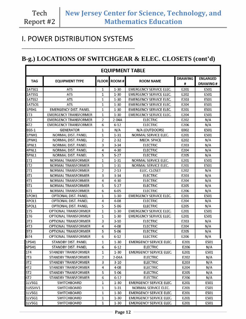
B-g.) LOCATIONS OF SWITCHGEAR & ELEC. CLOSETS
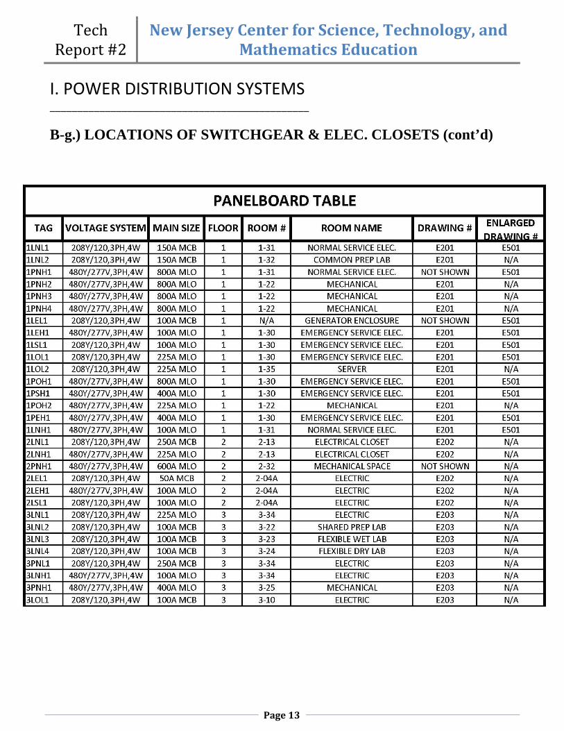
The two main electrical rooms are located on the first floor. There are also two smaller electrical rooms on each floor as well. The distribution and branch panels as well as the transformers of the normal branch are separated from the backup systems. The components of the emergency, standby and optional standby branch components are in a different room than the normal ones.
The main normal branch electrical room houses the main transformer, switchgear, and some distribution panels. The 2nd through 6th level normal electrical rooms are on the west side of the building. These also contain distribution panels, low voltage step down transformers to the 208Y/120V system, and branch panels. Some small normal branch panels are in labs too. Large mechanical equipment panels are located in their respective rooms.
The main emergency electrical room houses the four automatic transfer switches, the generator switchboard, and distribution panels. The generator itself is at the end of a driveway along the east side of the building near the loading dock. The emergency electrical rooms on the other levels are inside the circular elevator core walls near the center of the building. These emergency electrical rooms have mostly the same contents as their normal branch counter parts.
Tech Report #2
New Jersey Center for Science, Technology, and Mathematics Education
Page 12
I. POWER DISTRIBUTION SYSTEMS _______________________________________________ B-g.) LOCATIONS OF SWITCHGEAR & ELEC. CLOSETS (cont’d)
Tech Report #2
New Jersey Center for Science, Technology, and Mathematics Education
Page 13
I. POWER DISTRIBUTION SYSTEMS _______________________________________________ B-g.) LOCATIONS OF SWITCHGEAR & ELEC. CLOSETS (cont’d)

Tech Report #2
New Jersey Center for Science, Technology, and Mathematics Education
Page 14
I. POWER DISTRIBUTION SYSTEMS _______________________________________________ B-g.) LOCATIONS OF SWITCHGEAR & ELEC. CLOSETS (cont’d)

Tech Report #2
New Jersey Center for Science, Technology, and Mathematics Education
Page 15
I. POWER DISTRIBUTION SYSTEMS _______________________________________________
B-h.) OVER-CURRENT DEVICES (See Specifications 260475 Protective Devices)
The main over-current device on the primary side of substation ‘1USSHV1’ is rated for 15 KV and 600A. It is a combination switch and fuse. The main over-current device on the secondary side of the substation is set to trip at 4000A and also has a 4000A frame. It is a power air type of circuit breaker. They use compressed air to extinguish the arc of electricity when the circuit is broken. It is interchangeable with ground fault interrupting capabilities. Interchangeable means the breaker is a pull out type, which is beneficial for servicing.
The secondary branch devices are all power air type breakers as well. They are of the draw-out type like the main circuit breaker for servicing reasons. Only the 1600A breaker for the bus duct ‘1PBP1’ has GFI capabilities. It also has an electrical power management system (EPMS). These systems help control energy costs by reporting more accurate and useful energy cost reports. These systems also report when a breaker has tripped. A typical distribution panel has standard thermal magnetic breakers that are non interchangeable. Both the main breakers and secondary ones are this type.
For typical lighting panel boards, they are all main lug only. For lighting panel boards fed from a bus duct, there are fused disconnects in the electrical rooms to protect them. A typical lab panel board has a standard thermal magnetic breaker with a shunt trip. This shunt trip allows for a push button to turn off the main breaker in the panel board. The button is most likely located inside the room by the door because the panels are located just outside of the room. For circuits up to 600A, class RK1 fuses with dual element time delay are used. Dual element time delay allows for the fuse to be sized much closer to actual motor loads than single element. They are nonrenewable fuses. For motor and transformer circuits from 601-1200A, Class L time delay fuses are specified. A Class L fuse is the current limiting type and is fabricated for the protection of feeders and service equipment. For non inductive circuits from 601-1200A, the building uses Class L fast acting fuses. B-i.) TRANSFORMERS (See specifications 2604610 Low Voltage Transformers, 260320 Medium Voltage Transformers) The main transformer is the only one in the building that is K-rated. It is rated at 2500 KVA, however due to the forced air mechanical equipment designed for it, the transformer is really rated at 3333 KVA. The transformer steps down the 13.2 KV utility service to a 480Y/277V system for substation ‘1USSHV1’. This transformer and built integrally into this substation. There are minor

Tech Report #2
New Jersey Center for Science, Technology, and Mathematics Education
Page 16
I. POWER DISTRIBUTION SYSTEMS _______________________________________________
B-h.) TRANSFORMER (continued)
transformers in both the normal and emergency electrical rooms on each floor. These transformers step down the feeders from the 480Y/277V distribution panels to the 208Y/120V system. The normal transformers are generally much larger due to the fact that the generator can only provide so much power for the emergency and standby branches. It is possible that most of the minor transformers are K-Rated because this is a technology education building, so there is a lot of computer load. The schematics do not note whether these transformers are K-rated or not.

Tech Report #2
New Jersey Center for Science, Technology, and Mathematics Education
Page 17
I. POWER DISTRIBUTION SYSTEMS _______________________________________________
B-j.) SPECIAL SYSTEMS
One piece of special equipment is a transient voltage surge suppression system (TVSS). This piece of equipment is installed immediately after the main breaker of the substation ‘1USSHV1’. Surges can come from lightning, but this accounts for only 20% of the surges. Most of the surge problems occur due to equipment inside the building. This happens when motors, transformers, and copiers are turned on and off. This system protects from all sorts of electronic equipment and motors. (itvss.com) Other pieces of special equipment are the automatic transfer switches. This equipment is discussed in detail in Section B-f on pages 7-8. There is a 3D Cave in the building too. This is a virtual reality technology that allows for presentations
B-k.) LIGHTING LOADS
The lighting for this building is mostly fluorescent in order to meet ASHRAE Std. 90.1 requirements. This owner desires a LEED® Gold rated building, and this standard is cited for its power per area maximum values. Many spaces have two different fixtures with two different CCT’s. The different CCT of the lamps provides flexibility for different functions. However there is a high possibility that these lamps may not be installed in the correct fixture by the contractor. There are low voltage control panels on every floor’s electrical room. Many fixtures are equipped with dimming ballast for flexibility.

Tech Report #2
New Jersey Center for Science, Technology, and Mathematics Education
Page 18
I. POWER DISTRIBUTION SYSTEMS _______________________________________________
B-j.) LIGHTING LOADS (continued)

Tech Report #2
New Jersey Center for Science, Technology, and Mathematics Education
Page 19
I. POWER DISTRIBUTION SYSTEMS _______________________________________________
B-i.) MECHANICAL AND OTHER LOADS
There are 6 air handling units serving this building (AHU-1 through 6). AHU-7 will serve the future tenant in the restaurant space. There is a 300 ton closed cell cooling tower. The system designed is a four pipe open system. The four pipe system does not have to be changed to heating or cooling for when the seasons change. There are three boilers for wintertime heating as well.
For architectural loads, a lot of information was missing. The equipment is being specified by the university and it is under construction at this time, so finding the loads proved to be difficult. There is a 3d cave that is definitely power intensive. There are two passenger elevators and one freight type in the central core of the NJCSTME Building.
The plumbing loads were not listed as well. There is a 100 gallon storage electric hot water heater on the first floor. Most of the pumps must have been included into the mechanical equipment section.

Tech Report #2
New Jersey Center for Science, Technology, and Mathematics Education
Page 20
I. POWER DISTRIBUTION SYSTEMS _______________________________________________
B-i.) MECHANICAL AND OTHER LOADS (cont’d)

Tech Report #2
New Jersey Center for Science, Technology, and Mathematics Education
Page 21
I. POWER DISTRIBUTION SYSTEMS _______________________________________________
B-i.) MECHANICAL AND OTHER LOADS (cont’d)

Tech Report #2
New Jersey Center for Science, Technology, and Mathematics Education
Page 22
I. POWER DISTRIBUTION SYSTEMS _______________________________________________
B-m.) SERVICE ENTRANCE SIZE
The service entrance size was calculated by three methods for three different stages of design. The conceptual stage uses load per square foot values to calculate a rough estimate. The NJCSTME Building is a combination of classrooms and college laboratories. The area was split by these two types because the lab VA/SF value was significantly higher. The restaurant shell was included under the classroom space. The service size ended up being the same as the actual designed at 4000A on a 480Y/277 voltage system with a 25% growth factor included. Usually this estimate will be more than the actual size. The 3D cave load information is not known because it is being designed and specified by the University. This could require more power, but not enough to size it over 4000A
For the schematic stage, the load per square foot was used once again. However the building was broken down into components and their respective load per square foot values. Historical records of this building type’s loads per square foot could not be obtained by the company who designed this project. The packet provided contains all the values used for this part. The elevators sued a general load per amount. This size also turned out to be the actual size designed.
For the final method, the actual loads were used. The only exceptions were the lighting and receptacle loads. The loads calculated in the schematic phase for these loads were used once again. The demand factors were applied to their respective loads. A lot of the architectural equipment from the 3D Cave and the A/V for the auditorium is unknown since the University is solving these problems. The final service is a lot lower than the actual at 3000A.
In conclusion, I think that this building’s service is probably oversized. This was designed by a large architectural engineering firm. A lot of times they are rushed to finish their electrical designs. The structural design is the most important on a lot of these jobs, so the most attention is taken to that.

Tech Report #2
New Jersey Center for Science, Technology, and Mathematics Education
Page 23
I. POWER DISTRIBUTION SYSTEMS _______________________________________________
B-m.) SERVICE ENTRANCE SIZE (cont’d)

Tech Report #2
New Jersey Center for Science, Technology, and Mathematics Education
Page 24
I. POWER DISTRIBUTION SYSTEMS _______________________________________________
B-m.) SERVICE ENTRANCE SIZE (cont’d)
Tech Report #2
New Jersey Center for Science, Technology, and Mathematics Education
Page 25
I. POWER DISTRIBUTION SYSTEMS _______________________________________________
B-n.) ENVIRONMENTAL STEWARDSHIP DESIGN
Environmental Stewardship was an important consideration in the design of the NJCSTME Building. Kean University intends to have a LEED® Gold Rating at the end of construction. However there was not much on the electrical end designed for energy conservation. The main focus is using a great deal of fluorescent luminaires to cut down on energy costs. Fluorescent lighting is very energy efficient, so this type is utilized in every space. The main switchboard also has an EPMS, which will help determine whether the equipment is operating efficiently or not.
B-o.) DESIGN ISSUES One of the major design issues was the choice of whether to distribute power to upper floors with either conduit or bus duct. Bus duct is a very expensive initial cost because it is made of aluminum. However for distributing power to other floors it is less labor intensive. This is due to the fact that instead of making all the penetrations in the slab and fastening ever conduit run, there is just one rectangular penetration and riser to secure. Green issues could have caused this decision seeing how it will be a LEED® Gold Rated building. A bus duct uses much less material and electrical power to install, so it is more environmentally benign.

Tech Report #2
New Jersey Center for Science, Technology, and Mathematics Education
Page 26
II. COMMUNICATION SYSTEMS ____________________________________________________________________________________ B-a.) COMMUNICATION SYSTEMS SUMMARY DESCRIPTION
The telecommunications are tied in from the existing building Vaughn-Eames Hall. There is an existing duct bank outside the south wall of this hall. It runs from there to the intersection of Morris Avenue and Kean Drive. This is the point where the new duct bank is connected. The new duct bank runs to a manhole near the generator. The duct bank terminates at Server Room 1-35. The data wires are distributed throughout the building by 18” and 12” wide wire mesh metal cable tray.
The fire alarm system is a pre-action type. This means a smoke detector sends a warning to the fire alarm control panel that smoke from a fire has been detected. The sprinklers do not actually open until the heat from the fire melts the fusible link. There are speaker strobes in all of the corridors of the building with a 75 candela rating. There are also speaker strobes for large spaces such as the lower lobby, executive center, and auditorium. In all other rooms there are 75 candela strobes. There are fire alarm terminal cabinets in each emergency electric room. The fire command center is on the second floor. There are also two pre-action control panels, one on the 1st floor and one on the 3rd.