TCS Book of Classic N Installations v1 - mvns.railfan.net
37
TCS Book of Classic N Installations v1.21 www.tcsdcc.com Phone: 215-453-9145 [email protected] Fax: 215-257-0735 A simple guide to installing Classic N Decoders To use this installation book, first read through the generic installation. Next, find the specific locomotive you would like to install a decoder in, and then use these two installation guides together to get great results every time. CN CN-GP
Transcript of TCS Book of Classic N Installations v1 - mvns.railfan.net

TCS Book of Classic N Installations v1.21
www.tcsdcc.comPhone: 215-453-9145
[email protected]: 215-257-0735
A simple guide to installing Classic N Decoders
To use this installation book, fi rst read through the generic installation. Next, fi nd the specifi c locomotive
you would like to install a decoder in, and then use these two installation guides together to get great
results every time.
CN CN-GP
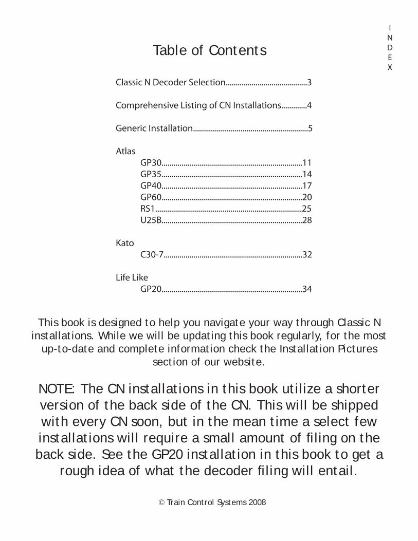
Table of Contents
INDEX
Classic N Decoder Selection.........................................3
Comprehensive Listing of CN Installations.............4
Generic Installation..........................................................5
Atlas GP30.......................................................................11 GP35.......................................................................14 GP40.......................................................................17 GP60.......................................................................20 RS1..........................................................................25 U25B.......................................................................28
Kato C30-7......................................................................32
Life Like GP20.......................................................................34
NOTE: The CN installations in this book utilize a shorter version of the back side of the CN. This will be shipped with every CN soon, but in the mean time a select few installations will require a small amount of fi ling on the back side. See the GP20 installation in this book to get a
rough idea of what the decoder fi ling will entail.
This book is designed to help you navigate your way through Classic N installations. While we will be updating this book regularly, for the most
up-to-date and complete information check the Installation Pictures section of our website.
© Train Control Systems 2008

“RS” Style FrameThe “RS” style locomotive frame is characterized by the two nubs protruding from the frame near either end of the locomotive as is shown in the picture found above.
Install the CN Decoder in “RS” style frames
Nubs
“GP” Style FrameThe “GP” style locomotive frame is characterized by the lack of metal nubs, which are seen on the “RS” style, and the lack of frame extensions found underneath the decoder on “U” style frames. Install the CN-GP Decoder in the
“GP” style frames
“U” Style FrameThe “U” style frame is characterized by the long extensions of metal which rest directly under the decoder on both sides of the front of the decoder. These sections of the frame will prevent the decoder from being installed safely and properly.
To install a decoder in a “U” style frame simply remove the section shown in yellow above from the FRONT SIDE ONLY, (do NOT modify the backside) and make sure it looks like the image
above on the right.Install the CN Decoder in “U” style frames
After Modifi cation
Before Modifi cation
Selecting the Right Classic N
3

Locomotive Is there any modifi cation needed? Decoder?Atlas GP30 In this book. Slight frame modifi cation CN-GPAtlas GP35 In this book. Slight frame modifi cation CNAtlas GP40 In this book. No modifi cation CN-GPAtlas GP60 In this book. Moderate frame modifi cation CN-GPAtlas RS1 In this book. No modifi cation CN
Atlas U25B In this book. Moderate frame modifi cation CNAtlas GP7 No modifi cation required CN-GPAtlas GP9 No modifi cation required CN-GPAtlas RS3 No modifi cation required CNAtlas SD60 No modifi cation required CNAtlas SD35 No modifi cation required CN
Atlas early GP38 No modifi cation required CNAtlas B30-7 No modifi cation required CNAtlas SD60M No modifi cation required CNAtlas SD50 No modication required CN
Atlas SD9 DCC-READY No modifi cation required CNAtlas GP38 No modifi cation required CNAtlas B40-8 No modifi cation required CN
Kato SD40 Advanced soldering required CN-GP
Intermountain SD40T-2 No modifi cation, tape under front of CN CN
Life Like GP18 No modifi cation required CN-GPLife Like GP20 Moderate board modifi cation required In this
book. Slight modifi cation neededCN-GP
Life Like GP60 No modifi cation required CN-GP
Classic N Decoder Installation Information
4
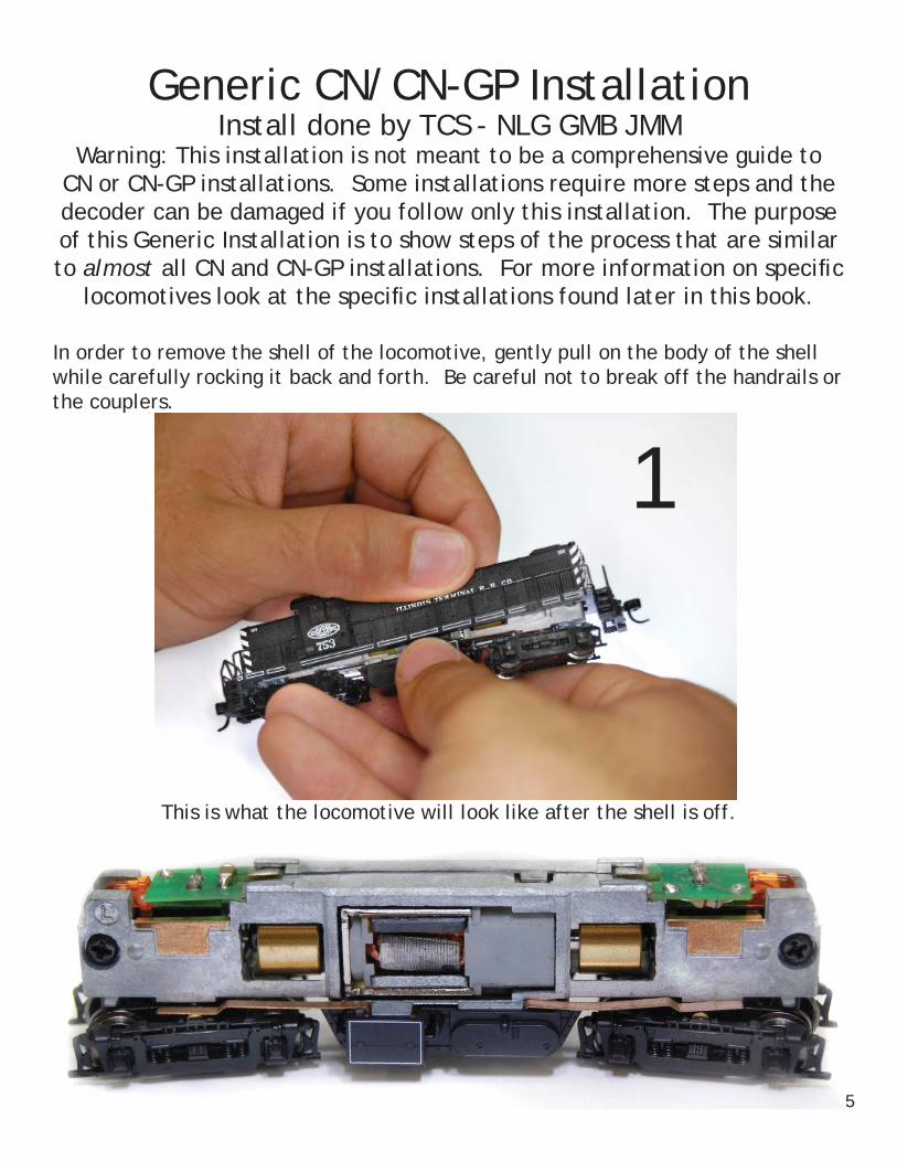
Generic CN/CN-GP InstallationInstall done by TCS - NLG GMB JMM
Warning: This installation is not meant to be a comprehensive guide to CN or CN-GP installations. Some installations require more steps and the decoder can be damaged if you follow only this installation. The purpose of this Generic Installation is to show steps of the process that are similar to almost all CN and CN-GP installations. For more information on specifi c
locomotives look at the specifi c installations found later in this book.
In order to remove the shell of the locomotive, gently pull on the body of the shell while carefully rocking it back and forth. Be careful not to break off the handrails or the couplers.
This is what the locomotive will look like after the shell is off.
1
5
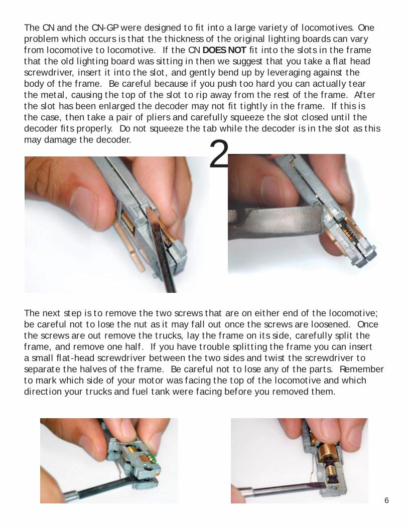
The next step is to remove the two screws that are on either end of the locomotive; be careful not to lose the nut as it may fall out once the screws are loosened. Once the screws are out remove the trucks, lay the frame on its side, carefully split the frame, and remove one half. If you have trouble splitting the frame you can insert a small fl at-head screwdriver between the two sides and twist the screwdriver to separate the halves of the frame. Be careful not to lose any of the parts. Remember to mark which side of your motor was facing the top of the locomotive and which direction your trucks and fuel tank were facing before you removed them.
The CN and the CN-GP were designed to fi t into a large variety of locomotives. One problem which occurs is that the thickness of the original lighting boards can vary from locomotive to locomotive. If the CN DOES NOT fi t into the slots in the frame that the old lighting board was sitting in then we suggest that you take a fl at head screwdriver, insert it into the slot, and gently bend up by leveraging against the body of the frame. Be careful because if you push too hard you can actually tear the metal, causing the top of the slot to rip away from the rest of the frame. After the slot has been enlarged the decoder may not fi t tightly in the frame. If this is the case, then take a pair of pliers and carefully squeeze the slot closed until the decoder fi ts properly. Do not squeeze the tab while the decoder is in the slot as this may damage the decoder.
2
6
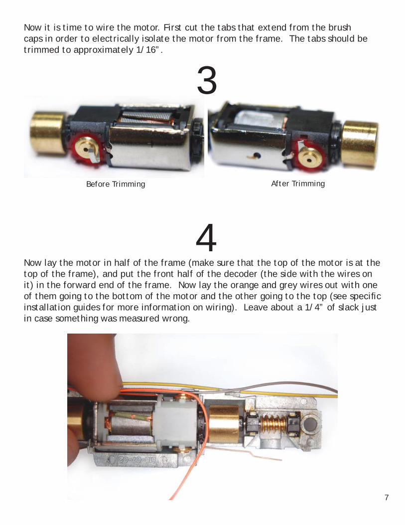
Now it is time to wire the motor. First cut the tabs that extend from the brush caps in order to electrically isolate the motor from the frame. The tabs should be trimmed to approximately 1/16”.
Now lay the motor in half of the frame (make sure that the top of the motor is at the top of the frame), and put the front half of the decoder (the side with the wires on it) in the forward end of the frame. Now lay the orange and grey wires out with one of them going to the bottom of the motor and the other going to the top (see specifi c installation guides for more information on wiring). Leave about a 1/4” of slack just in case something was measured wrong.
Before Trimming After Trimming
3
4
7

After the motor is wired up all of the parts can be put back inside the frame and the frame can be screwed together. Be sure to put the round black spacers back for the screws to go through.
Now strip about a 1/16” off of the end of the orange and grey wires, tin (add solder to) the stripped ends, tin the motor tabs, and attach the wires to the tabs. After this is completed wrap some Kapton tape around the motor in order to ensure that it is electrically isolated from the frame.
Most of the locomotives that the CN or CN-GP are installed in have a black motor casing like the one displayed below. This casing may be challenging to work with and may present a problem in routing the wires going to the motor. The motor wires route behind the motor casing and then up through the two halves of the frame. Most times, though, the wires end up pinched between the casing and the frame so the casing must be modifi ed. The best tool is an X-Acto knife or a razor knife. The plastic is very soft, so it is easy to cut but it also breaks rather easily. Do not cut straight into the plastic but rather do a scooping motion and slowly shave off small pieces of plastic until you are about half way through the casing so that the wires can route through it.
5
68

Once the frame is back together you can attach the yellow, black, and blue wires. Leave a lot of slack in these wires the fi rst time that they are attached in case there are any problems that are found during testing. After these wires are attached test the locomotive. The most common problem is that the motor will run backwards from the lights. This is because the locomotive manufacturers sometimes put the motors in upside down causing the grey and the orange wires to be soldered to the wrong side of the motor. Rather than swapping the orange and the grey wires, it is far easier to reprogram the decoder. First, put a value of 7 in CV 29; this causes everything (the motor and the lights) to run opposite from their original orientation. Now the motor is running in the proper direction and in order to change the lights put a value of 16 into CV 49 and a value of 0 into CV 50. Now the motor should be running in the proper directions and the lights should be matching the direction of the motor.
7
9
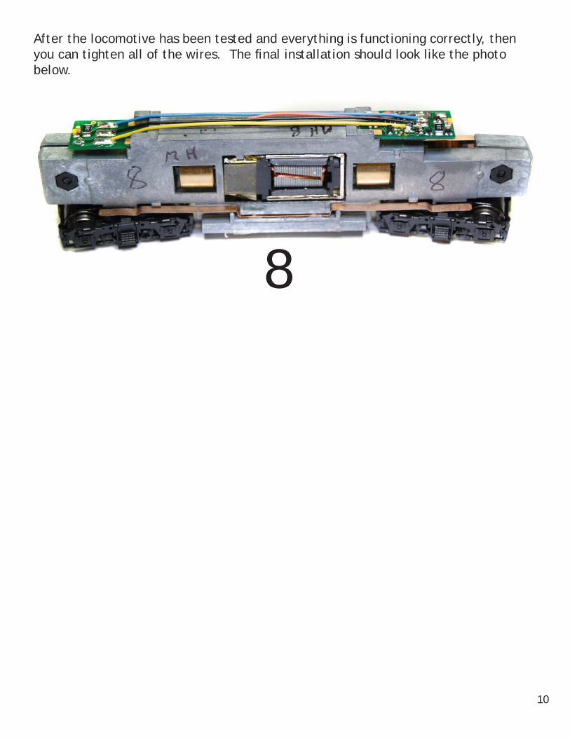
After the locomotive has been tested and everything is functioning correctly, then you can tighten all of the wires. The fi nal installation should look like the photo below.
8
10

Atlas GP-30CN-GP Installation
Some frame modifi cation requiredInstallation done by TCS - NLG, GMB, JMM
This is the GP-30 with the shell on before the decoder installation. See section 1 of Generic Installation
This is what the locomotive should look like once you get the Shell off.See section 1 of Generic Installation
Test your decoder in the locomotive and be sure it fi ts between the tabs of the frame before continuing on.
See section 2 of Generic Installation
Before reading this installation fi rst read through the Generic Installation found in the beginning of this book. There is information contained in this guide, however, that is not contained in the Generic Installation.
11
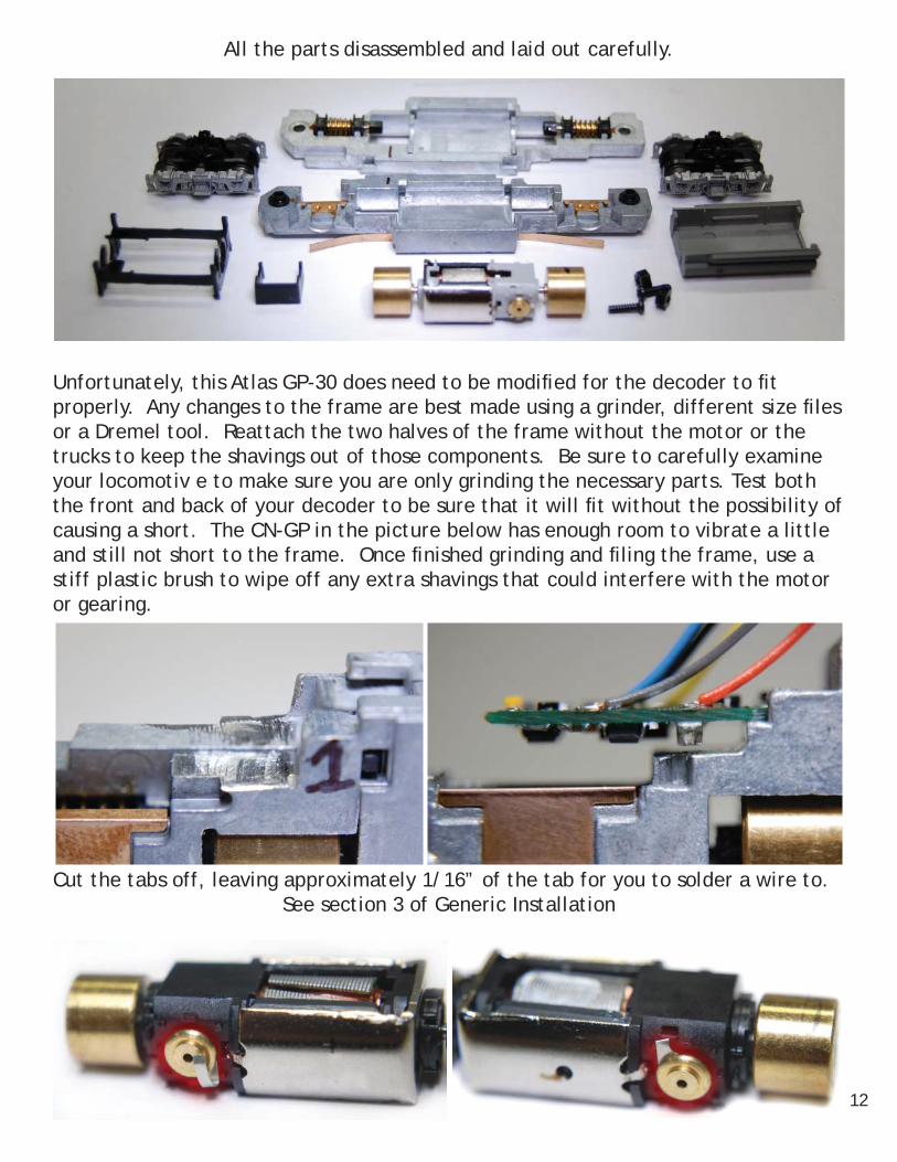
All the parts disassembled and laid out carefully.
Unfortunately, this Atlas GP-30 does need to be modifi ed for the decoder to fi t properly. Any changes to the frame are best made using a grinder, different size fi les or a Dremel tool. Reattach the two halves of the frame without the motor or the trucks to keep the shavings out of those components. Be sure to carefully examine your locomotiv e to make sure you are only grinding the necessary parts. Test both the front and back of your decoder to be sure that it will fi t without the possibility of causing a short. The CN-GP in the picture below has enough room to vibrate a little and still not short to the frame. Once fi nished grinding and fi ling the frame, use a stiff plastic brush to wipe off any extra shavings that could interfere with the motor or gearing.
Cut the tabs off, leaving approximately 1/16” of the tab for you to solder a wire to.See section 3 of Generic Installation
12

Next cut the wires and solder the grey wire to the bottom of the motor.See section 4 and 6 of Generic Installation
See section 5 of Generic Installation for instructions on the motor casing
Now it’s time to install the decoder.See sections 7, and 8 of Generic Installation
13

Atlas GP-35CN Installation
Some frame modifi cation requiredInstallation done by TCS - NLG, GMB, JMM
This is the GP-35 with the shell on before the decoder installation. See section 1 of Generic Installation
This is what the locomotive should look like once you get the Shell off.See section 1 of Generic Installation
Test your decoder in the locomotive and be sure it fi ts between the tabs of the frame before continuing on.
See section 2 of Generic Installation
Before reading this installation fi rst read through the Generic Installation found in the beginning of this book. There is information contained in this guide, however, that is not contained in the Generic Installation.
14
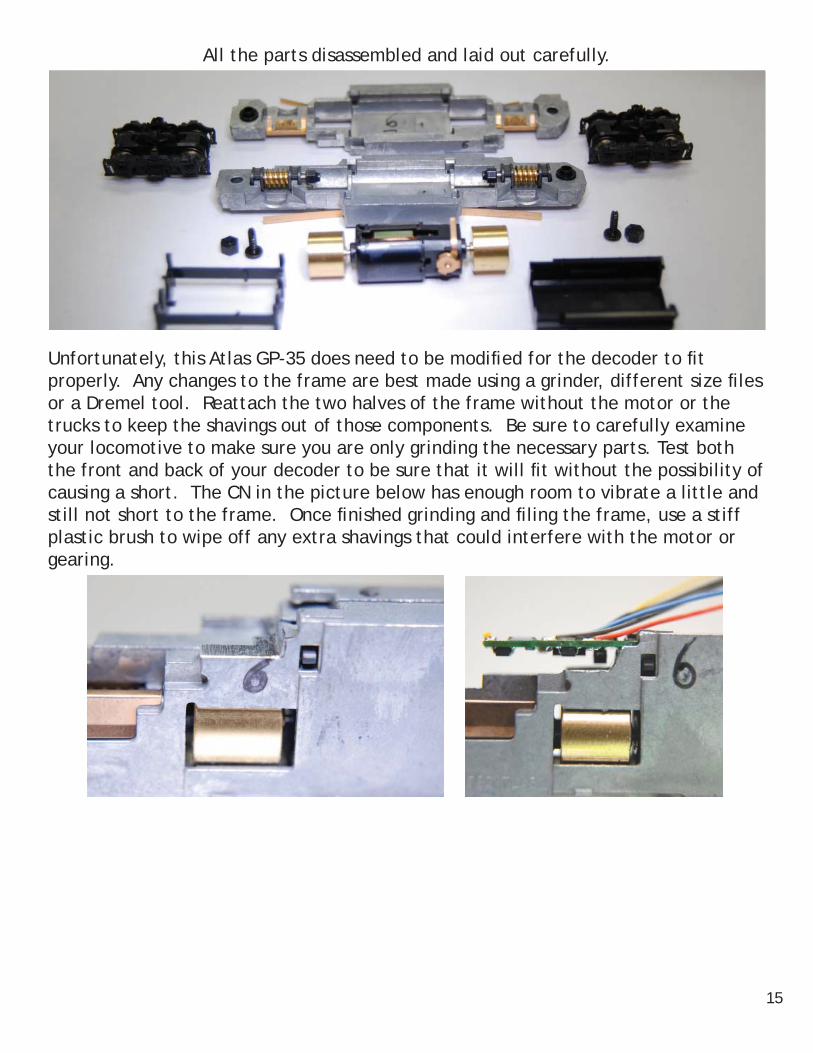
All the parts disassembled and laid out carefully.
Unfortunately, this Atlas GP-35 does need to be modifi ed for the decoder to fi t properly. Any changes to the frame are best made using a grinder, different size fi les or a Dremel tool. Reattach the two halves of the frame without the motor or the trucks to keep the shavings out of those components. Be sure to carefully examine your locomotive to make sure you are only grinding the necessary parts. Test both the front and back of your decoder to be sure that it will fi t without the possibility of causing a short. The CN in the picture below has enough room to vibrate a little and still not short to the frame. Once fi nished grinding and fi ling the frame, use a stiff plastic brush to wipe off any extra shavings that could interfere with the motor or gearing.
15

Cut the tabs off, leaving approximately 1/16” of the tab for you to solder a wire to.See section 3 of Generic Installation
Next cut the wires and solder the orange wire to the bottom of the motor.See section 4 and 6 of Generic Installation
See section 5 of Generic Installation for instructions on the motor casing
Now it’s time to install the decoder.See sections 7, and 8 of Generic Installation
16

Atlas GP-40CN-GP Installation
Installation by NLG, GMB
This is the GP-40 with the shell on before the decoder installation. See section 1 of Generic Installation
Before reading this installation fi rst read through the Generic Installation found in the beginning of this book. There is information contained in this guide, however, that is not contained in the Generic Installation.
This is what the locomotive should look like once you get the Shell off.See section 1 of Generic Installation
17

All the parts disassembled and laid out carefully.
Cut the tabs off, leaving approximately 1/16” of the tab for you to solder a wire to.See section 3 of Generic Installation
Next cut the wires and solder the grey wire to the bottom of the motor.See section 4 and 6 of Generic Installation
See section 5 of Generic Installation for instructions on the motor casing18
Now it’s time to install the decoder.See sections 7, and 8 of Generic Installation
19

Atlas GP-60CN-GP Installation
Some frame modifi cationsInstall done by TCS - NLG GMB
This is the GP-60 with the shell on before the decoder installation. See section 1 of Generic Installation
Before reading this installation fi rst read through the Generic Installation found in the beginning of this book. There is information contained in this guide, however, that is not contained in the Generic Installation.
This is what the locomotive should look like once you get the Shell off.See section 1 of Generic Installation
Test your decoder in the locomotive and be sure it fi ts between the tabs of the frame before continuing on.
See section 2 of Generic Installation
20

There are several issues with this installation that make it short out once the locomotive is all put back together. The fi rst issue is that the spacers that isolate the two sides of the frame from each other are rather skinny and don’t allow enough room for the wires to route from the motor to the decoder. The way to fi x this is to simply fi le a slot in one of the halves of the frame for the wires to go through.
All the parts disassembled and laid out carefully.
21

The next problem is that the motor is too close to the inside of the frame so you must grind away part of the frame around the motor. The sections that must be removed are marked with a black marker in the photo below. It seems that the best method for doing this seems to be using a dremel tool with some sort of grinding bit. If you do not have a dremel tool at your disposal a fi le could be utilized, but be careful to maintain the curve that is found in the frame around the motor. The photo to the right shows the frame after it has been carved out. The arrow is pointing to the section that required the most removal. A good method for knowing if enough of the frame was removed is to hold the motor in half of the frame and then look at a light through the frame. You should be able to see light coming between the motor and the frame. The arrow in the photo on the right is showing where the most amount of grinding was needed.
22

Cut the tabs off, leaving approximately 1/16” of the tab for you to solder a wire to.See section 3 of Generic Installation
Next cut the wires and solder the orange wire to the bottom of the motor.See section 4 and 6 of Generic Installation
23

Now it’s time to install the decoder.See sections 7 and 8 of Generic Installation
Now tighten the wires for a fi nished lookSee section 9 of Generic Installation
24

Atlas RS-1CN Installation
Installation by NLG, GMB
This is the RS-1 with the shell on before the decoder installation. See section 1 of Generic Installation
Before reading this installation fi rst read through the Generic Installation found in the beginning of this book. There is information contained in this guide, however, that is not contained in the Generic Installation.
This is what the locomotive should look like once you get the Shell off.See section 1 of Generic Installation
Test your decoder in the locomotive and be sure it fi ts between the tabs of the frame before continuing on.
See section 2 of Generic Installation
25

All the parts disassembled and laid out carefully.
Cut the tabs off, leaving approximately 1/16” of the tab for you to solder a wire to.See section 3 of Generic Installation
Next cut the wires and solder the orange wire to the bottom of the motor.See section 4 and 6 of Generic Installation
26

Now it’s time to install the decoder.See section 7 of Generic Installation
Now tighten the wires for a fi nished lookSee section 8 of Generic Installation
27

Atlas GE U25BCN Installation
Some frame modifi cation is required during this installation.Installation by TCS- JMM, GMB, NLG
Below is a picture of the loco before installation.See section 1 of Generic Installation
This is what the locomotive should look like once you get the shell off.
Before reading this installation fi rst read through the Generic Installation found in the beginning of this book. There is information contained in this guide, however, that is not contained in the Generic Installation.
Test your decoder in the locomotive and be sure it fi ts between the tabs of the frame before continuing on.
See section 2 of Generic Installation
28

Unfortunately, this Atlas GE U25B does need to be modifi ed for the decoder to fi t properly. The section of the frame that is marked with black in the photo on the left needs to be fi led away before the decoder can fi t into the slot without any issues. The photo on the right shows the frame after modifi cations. Enough of the frame should be removed to allow all parts of the decoder to have at least 1/8” clearance from the frame.
All the parts disassembled and laid out carefully.
29
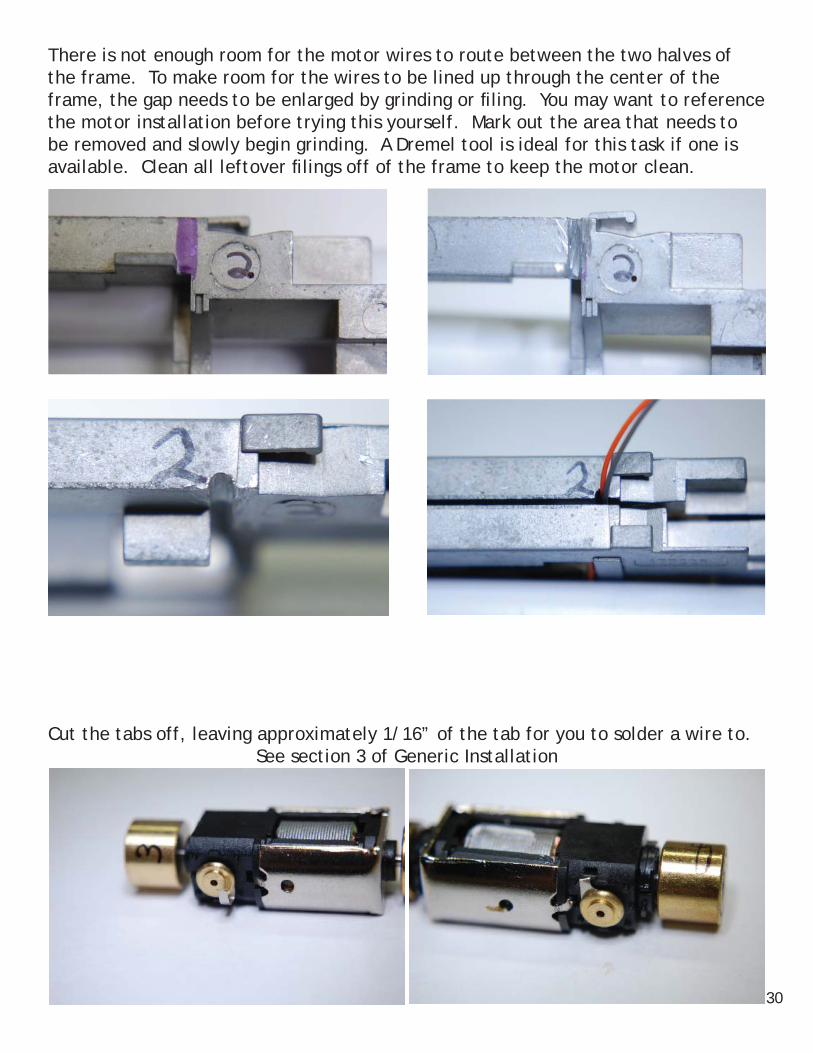
There is not enough room for the motor wires to route between the two halves of the frame. To make room for the wires to be lined up through the center of the frame, the gap needs to be enlarged by grinding or fi ling. You may want to reference the motor installation before trying this yourself. Mark out the area that needs to be removed and slowly begin grinding. A Dremel tool is ideal for this task if one is available. Clean all leftover fi lings off of the frame to keep the motor clean.
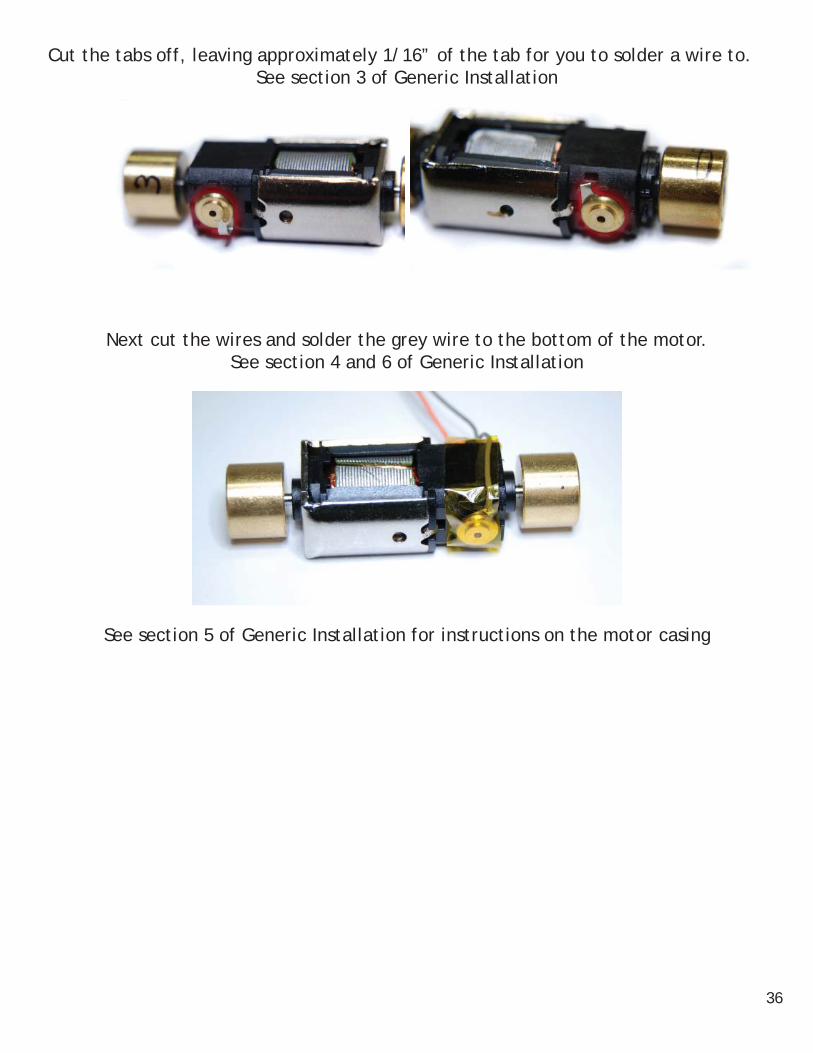
Cut the tabs off, leaving approximately 1/16” of the tab for you to solder a wire to.See section 3 of Generic Installation
30

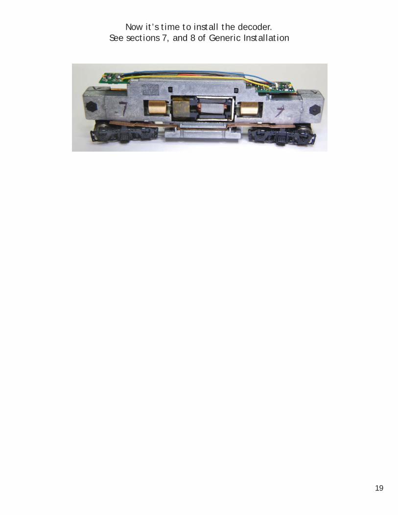
Next cut the wires and solder the gray wire to the bottom of the motor.See section 4 and 6 of Generic Installation
Now it’s time to install the decoder.See sections 7, 8 and 9 of Generic Installation
31

Kato C30-7CN Installation
*Frame modifi cation required
C30-7 Locomotive before any modifi cations. 1
The front end of this Locomotive will need to be fi led away. The black marks below show the area that will need to be modifi ed. Be careful of the small nubs on either side of the frame because they are what hold the shell on and don’t need to be fi led off for a proper installation. 3 & 4
Before Before

The motor will then need to be isolated from the frame. Clip the brush tabs that are on either side of the motor to 1/8” in length (reference sections 5 & 6 of our Generic Installation Guide). Solder the Orange wire to the bottom side of the motor and the grey to the top. Wrap all contact points in kapton tape and reassemble.
Once assembled, tighten all the wires to use as little excess space as possible. 7 & 8
The Locomotive should look the same as it did before the installation. 9

LifeLike GP-20CN-GP Installation
For this installation, both the front and back end of the decoder need to be modifi ed for the installation to be done properly.
Installation by TCS- JMM, GMB, NLG
Before reading this installation fi rst read through the Generic Installation found in the beginning of this book. There is information contained in this guide, however, that is not contained in the Generic Installation.
This is the GP-20 with the shell on before the decoder installation. See section 1 of Generic Installation
This is what the locomotive should look like once you get the shell off.See section 1 of Generic Installation
Test your decoder in the locomotive and be sure it fi ts between the tabs of the frame before continuing on.
See section 2 of Generic Installation
34

Although the frame is set up to hold this decoder without any problems, the shell that comes with this locomotive, is too small for the decoder to fi t beneath the light tubes. The decoder itself needs to be shaved down about 1/16” on both the front and the back. Below are the before and after pictures of both the front and the back of this CN-GP. Be very careful with the CN-GP front because of the electrical components that could get knocked off. A motorized sander will work well, but you must be careful because they can remove a signifi cant amount of material in a short period of time.
Front BackBefore
After
All the parts disassembled and laid out carefully.
35
Cut the tabs off, leaving approximately 1/16” of the tab for you to solder a wire to.See section 3 of Generic Installation
Next cut the wires and solder the grey wire to the bottom of the motor.See section 4 and 6 of Generic Installation
See section 5 of Generic Installation for instructions on the motor casing
36

Now it’s time to install the decoder.See sections 7 and 8 of Generic Installation
37