TBS1000B and TBS1000B-EDU Series Digital Storage ...eyler/phys3150/R/TBS1052B_User_Manual.pdf ·...
154
xx TBS1000B and TBS1000B-EDU Series Digital Storage Oscilloscopes ZZZ User Manual *P077088600* 077-0886-00
-
Upload
truonghanh -
Category
Documents
-
view
227 -
download
0
Transcript of TBS1000B and TBS1000B-EDU Series Digital Storage ...eyler/phys3150/R/TBS1052B_User_Manual.pdf ·...

xx
TBS1000B and TBS1000B-EDU SeriesDigital Storage Oscilloscopes
ZZZ
User Manual
*P077088600*
077-0886-00


TBS1000B and TBS1000B-EDU SeriesDigital Storage Oscilloscopes
ZZZ
User Manual
xx
www.tektronix.com077-0886-00

Copyright © Tektronix. All rights reserved. Licensed software products are owned by Tektronix or its subsidiariesor suppliers, and are protected by national copyright laws and international treaty provisions.
Tektronix products are covered by U.S. and foreign patents, issued and pending. Information in this publicationsupersedes that in all previously published material. Specifications and price change privileges reserved.
TEKTRONIX and TEK are registered trademarks of Tektronix, Inc.
OpenChoice™ is a registered trademark of Tektronix, Inc.
PictBridge is a registered trademark of the Standard of Camera & Imaging Products Association CIPADC-001-2003 Digital Photo Solutions for Imaging Devices.
Contacting Tektronix
Tektronix, Inc.14150 SW Karl Braun DriveP.O. Box 500Beaverton, OR 97077USA
For product information, sales, service, and technical support:In North America, call 1-800-833-9200.Worldwide, visit www.tektronix.com to find contacts in your area.

TBS1000B and TBS1000B-EDU OscilloscopesWarranty
Tektronix warrants that the product will be free from defects in materials and workmanship for a period of five (5)years from the date of original purchase from an authorized Tektronix distributor. If the product proves defectiveduring this warranty period, Tektronix, at its option, either will repair the defective product without charge forparts and labor, or will provide a replacement in exchange for the defective product. Batteries are excluded fromthis warranty. Parts, modules and replacement products used by Tektronix for warranty work may be new orreconditioned to like new performance. All replaced parts, modules and products become the property of Tektronix.
In order to obtain service under this warranty, Customer must notify Tektronix of the defect before the expirationof the warranty period and make suitable arrangements for the performance of service. Customer shall beresponsible for packaging and shipping the defective product to the service center designated by Tektronix,shipping charges prepaid, and with a copy of customer proof of purchase. Tektronix shall pay for the return of theproduct to Customer if the shipment is to a location within the country in which the Tektronix service center islocated. Customer shall be responsible for paying all shipping charges, duties, taxes, and any other charges forproducts returned to any other locations.
This warranty shall not apply to any defect, failure or damage caused by improper use or improper or inadequatemaintenance and care. Tektronix shall not be obligated to furnish service under this warranty a) to repair damageresulting from attempts by personnel other than Tektronix representatives to install, repair or service the product;b) to repair damage resulting from improper use or connection to incompatible equipment; c) to repair any damageor malfunction caused by the use of non-Tektronix supplies; or d) to service a product that has been modified orintegrated with other products when the effect of such modification or integration increases the time or difficultyof servicing the product.
THIS WARRANTY IS GIVEN BY TEKTRONIX WITH RESPECT TO THE PRODUCT IN LIEU OF ANYOTHER WARRANTIES, EXPRESS OR IMPLIED. TEKTRONIX AND ITS VENDORS DISCLAIM ANYIMPLIED WARRANTIES OF MERCHANTABILITY OR FITNESS FOR A PARTICULAR PURPOSE.TEKTRONIX' RESPONSIBILITY TO REPAIR OR REPLACE DEFECTIVE PRODUCTS IS THE SOLEAND EXCLUSIVE REMEDY PROVIDED TO THE CUSTOMER FOR BREACH OF THIS WARRANTY.TEKTRONIX AND ITS VENDORS WILL NOT BE LIABLE FOR ANY INDIRECT, SPECIAL, INCIDENTAL,OR CONSEQUENTIAL DAMAGES IRRESPECTIVE OF WHETHER TEKTRONIX OR THE VENDOR HASADVANCE NOTICE OF THE POSSIBILITY OF SUCH DAMAGES.
[W19 – 03AUG12]

TPP0051, TPP0101 and TPP0201 ProbesWarranty
Tektronix warrants that this product will be free from defects in materials and workmanship for a period of one (1)year from the date of shipment. If any such product proves defective during this warranty period, Tektronix, at itsoption, either will repair the defective product without charge for parts and labor, or will provide a replacementin exchange for the defective product. Parts, modules and replacement products used by Tektronix for warrantywork may be new or reconditioned to like new performance. All replaced parts, modules and products becomethe property of Tektronix.
In order to obtain service under this warranty, Customer must notify Tektronix of the defect before the expiration ofthe warranty period and make suitable arrangements for the performance of service. Customer shall be responsiblefor packaging and shipping the defective product to the service center designated by Tektronix, with shippingcharges prepaid. Tektronix shall pay for the return of the product to Customer if the shipment is to a location withinthe country in which the Tektronix service center is located. Customer shall be responsible for paying all shippingcharges, duties, taxes, and any other charges for products returned to any other locations.
This warranty shall not apply to any defect, failure or damage caused by improper use or improper or inadequatemaintenance and care. Tektronix shall not be obligated to furnish service under this warranty a) to repair damageresulting from attempts by personnel other than Tektronix representatives to install, repair or service the product;b) to repair damage resulting from improper use or connection to incompatible equipment; c) to repair any damageor malfunction caused by the use of non-Tektronix supplies; or d) to service a product that has been modified orintegrated with other products when the effect of such modification or integration increases the time or difficultyof servicing the product.
THIS WARRANTY IS GIVEN BY TEKTRONIX WITH RESPECT TO THE PRODUCT IN LIEU OF ANYOTHER WARRANTIES, EXPRESS OR IMPLIED. TEKTRONIX AND ITS VENDORS DISCLAIM ANYIMPLIED WARRANTIES OF MERCHANTABILITY OR FITNESS FOR A PARTICULAR PURPOSE.TEKTRONIX' RESPONSIBILITY TO REPAIR OR REPLACE DEFECTIVE PRODUCTS IS THE SOLEAND EXCLUSIVE REMEDY PROVIDED TO THE CUSTOMER FOR BREACH OF THIS WARRANTY.TEKTRONIX AND ITS VENDORS WILL NOT BE LIABLE FOR ANY INDIRECT, SPECIAL, INCIDENTAL,OR CONSEQUENTIAL DAMAGES IRRESPECTIVE OF WHETHER TEKTRONIX OR THE VENDOR HASADVANCE NOTICE OF THE POSSIBILITY OF SUCH DAMAGES.
[W2 – 15AUG04]

Table of Contents
Important safety information . . . . . . . . . . . . . . . . . . . . . . . . . . . . . . . . . . . . . . . . . . . . . . . . . . . . . . . . . . . . . . . . . . . . . . . . . . . . . . . . . . . . . ivGeneral safety summary . . . . . . . . . . . . . . . . . . . . . . . . . . . . . . . . . . . . . . . . . . . . . . . . . . . . . . . . . . . . . . . . . . . . . . . . . . . . . . . . . . . . . ivService safety summary .. . . . . . . . . . . . . . . . . . . . . . . . . . . . . . . . . . . . . . . . . . . . . . . . . . . . . . . . . . . . . . . . . . . . . . . . . . . . . . . . . . . . viiTerms in this manual . . . . . . . . . . . . . . . . . . . . . . . . . . . . . . . . . . . . . . . . . . . . . . . . . . . . . . . . . . . . . . . . . . . . . . . . . . . . . . . . . . . . . . . . viiiSymbols and terms on the product . . . . . . . . . . . . . . . . . . . . . . . . . . . . . . . . . . . . . . . . . . . . . . . . . . . . . . . . . . . . . . . . . . . . . . . . . viii
Compliance information .. . . . . . . . . . . . . . . . . . . . . . . . . . . . . . . . . . . . . . . . . . . . . . . . . . . . . . . . . . . . . . . . . . . . . . . . . . . . . . . . . . . . . . . . . ixEMC compliance . . . . . . . . . . . . . . . . . . . . . . . . . . . . . . . . . . . . . . . . . . . . . . . . . . . . . . . . . . . . . . . . . . . . . . . . . . . . . . . . . . . . . . . . . . . . . ixSafety compliance .. . . . . . . . . . . . . . . . . . . . . . . . . . . . . . . . . . . . . . . . . . . . . . . . . . . . . . . . . . . . . . . . . . . . . . . . . . . . . . . . . . . . . . . . . . . xiEnvironmental considerations . . . . . . . . . . . . . . . . . . . . . . . . . . . . . . . . . . . . . . . . . . . . . . . . . . . . . . . . . . . . . . . . . . . . . . . . . . . . . . xiv
Getting Started . . . . . . . . . . . . . . . . . . . . . . . . . . . . . . . . . . . . . . . . . . . . . . . . . . . . . . . . . . . . . . . . . . . . . . . . . . . . . . . . . . . . . . . . . . . . . . . . . . . . . . 1General Features . . . . . . . . . . . . . . . . . . . . . . . . . . . . . . . . . . . . . . . . . . . . . . . . . . . . . . . . . . . . . . . . . . . . . . . . . . . . . . . . . . . . . . . . . . . . . . . 1Installation . . . . . . . . . . . . . . . . . . . . . . . . . . . . . . . . . . . . . . . . . . . . . . . . . . . . . . . . . . . . . . . . . . . . . . . . . . . . . . . . . . . . . . . . . . . . . . . . . . . . . . 2Functional Check . . . . . . . . . . . . . . . . . . . . . . . . . . . . . . . . . . . . . . . . . . . . . . . . . . . . . . . . . . . . . . . . . . . . . . . . . . . . . . . . . . . . . . . . . . . . . . 4Probe Safety . . . . . . . . . . . . . . . . . . . . . . . . . . . . . . . . . . . . . . . . . . . . . . . . . . . . . . . . . . . . . . . . . . . . . . . . . . . . . . . . . . . . . . . . . . . . . . . . . . . . 5Manual Probe Compensation .. . . . . . . . . . . . . . . . . . . . . . . . . . . . . . . . . . . . . . . . . . . . . . . . . . . . . . . . . . . . . . . . . . . . . . . . . . . . . . . . 6Probe Attenuation Setting.. . . . . . . . . . . . . . . . . . . . . . . . . . . . . . . . . . . . . . . . . . . . . . . . . . . . . . . . . . . . . . . . . . . . . . . . . . . . . . . . . . . . 6Current Probe Scaling .. . . . . . . . . . . . . . . . . . . . . . . . . . . . . . . . . . . . . . . . . . . . . . . . . . . . . . . . . . . . . . . . . . . . . . . . . . . . . . . . . . . . . . . . 7Self Calibration . . . . . . . . . . . . . . . . . . . . . . . . . . . . . . . . . . . . . . . . . . . . . . . . . . . . . . . . . . . . . . . . . . . . . . . . . . . . . . . . . . . . . . . . . . . . . . . . 7Firmware Updates Through the Internet . . . . . . . . . . . . . . . . . . . . . . . . . . . . . . . . . . . . . . . . . . . . . . . . . . . . . . . . . . . . . . . . . . . . 8
Operating Basics. . . . . . . . . . . . . . . . . . . . . . . . . . . . . . . . . . . . . . . . . . . . . . . . . . . . . . . . . . . . . . . . . . . . . . . . . . . . . . . . . . . . . . . . . . . . . . . . . . . . 9Display Area .. . . . . . . . . . . . . . . . . . . . . . . . . . . . . . . . . . . . . . . . . . . . . . . . . . . . . . . . . . . . . . . . . . . . . . . . . . . . . . . . . . . . . . . . . . . . . . . . . . 9Using the Menu System.. . . . . . . . . . . . . . . . . . . . . . . . . . . . . . . . . . . . . . . . . . . . . . . . . . . . . . . . . . . . . . . . . . . . . . . . . . . . . . . . . . . . . 12Vertical Controls . . . . . . . . . . . . . . . . . . . . . . . . . . . . . . . . . . . . . . . . . . . . . . . . . . . . . . . . . . . . . . . . . . . . . . . . . . . . . . . . . . . . . . . . . . . . . . 12Horizontal Controls. . . . . . . . . . . . . . . . . . . . . . . . . . . . . . . . . . . . . . . . . . . . . . . . . . . . . . . . . . . . . . . . . . . . . . . . . . . . . . . . . . . . . . . . . . . 12Trigger Controls. . . . . . . . . . . . . . . . . . . . . . . . . . . . . . . . . . . . . . . . . . . . . . . . . . . . . . . . . . . . . . . . . . . . . . . . . . . . . . . . . . . . . . . . . . . . . . . 13Menu and Control Buttons. . . . . . . . . . . . . . . . . . . . . . . . . . . . . . . . . . . . . . . . . . . . . . . . . . . . . . . . . . . . . . . . . . . . . . . . . . . . . . . . . . . 14Input Connectors. . . . . . . . . . . . . . . . . . . . . . . . . . . . . . . . . . . . . . . . . . . . . . . . . . . . . . . . . . . . . . . . . . . . . . . . . . . . . . . . . . . . . . . . . . . . . . 15Other Front-Panel Items.. . . . . . . . . . . . . . . . . . . . . . . . . . . . . . . . . . . . . . . . . . . . . . . . . . . . . . . . . . . . . . . . . . . . . . . . . . . . . . . . . . . . . 16
Understanding Oscilloscope Functions . . . . . . . . . . . . . . . . . . . . . . . . . . . . . . . . . . . . . . . . . . . . . . . . . . . . . . . . . . . . . . . . . . . . . . . . . 17Setting Up the Oscilloscope . . . . . . . . . . . . . . . . . . . . . . . . . . . . . . . . . . . . . . . . . . . . . . . . . . . . . . . . . . . . . . . . . . . . . . . . . . . . . . . . . 17Triggering.. . . . . . . . . . . . . . . . . . . . . . . . . . . . . . . . . . . . . . . . . . . . . . . . . . . . . . . . . . . . . . . . . . . . . . . . . . . . . . . . . . . . . . . . . . . . . . . . . . . . . 18Acquiring Signals. . . . . . . . . . . . . . . . . . . . . . . . . . . . . . . . . . . . . . . . . . . . . . . . . . . . . . . . . . . . . . . . . . . . . . . . . . . . . . . . . . . . . . . . . . . . . 20Scaling and Positioning Waveforms .. . . . . . . . . . . . . . . . . . . . . . . . . . . . . . . . . . . . . . . . . . . . . . . . . . . . . . . . . . . . . . . . . . . . . . . 21Taking Measurements . . . . . . . . . . . . . . . . . . . . . . . . . . . . . . . . . . . . . . . . . . . . . . . . . . . . . . . . . . . . . . . . . . . . . . . . . . . . . . . . . . . . . . . . 23
Application Examples. . . . . . . . . . . . . . . . . . . . . . . . . . . . . . . . . . . . . . . . . . . . . . . . . . . . . . . . . . . . . . . . . . . . . . . . . . . . . . . . . . . . . . . . . . . . . 25Taking Simple Measurements . . . . . . . . . . . . . . . . . . . . . . . . . . . . . . . . . . . . . . . . . . . . . . . . . . . . . . . . . . . . . . . . . . . . . . . . . . . . . . . 26Using Autorange to Examine a Series of Test Points . . . . . . . . . . . . . . . . . . . . . . . . . . . . . . . . . . . . . . . . . . . . . . . . . . . . . 30Taking Cursor Measurements . . . . . . . . . . . . . . . . . . . . . . . . . . . . . . . . . . . . . . . . . . . . . . . . . . . . . . . . . . . . . . . . . . . . . . . . . . . . . . . 30Analyzing Signal Detail. . . . . . . . . . . . . . . . . . . . . . . . . . . . . . . . . . . . . . . . . . . . . . . . . . . . . . . . . . . . . . . . . . . . . . . . . . . . . . . . . . . . . . 35
TBS1000B and TBS1000B-EDU Series Oscilloscopes User Manual i

Table of Contents
Capturing a Single-Shot Signal . . . . . . . . . . . . . . . . . . . . . . . . . . . . . . . . . . . . . . . . . . . . . . . . . . . . . . . . . . . . . . . . . . . . . . . . . . . . . 36Measuring Propagation Delay . . . . . . . . . . . . . . . . . . . . . . . . . . . . . . . . . . . . . . . . . . . . . . . . . . . . . . . . . . . . . . . . . . . . . . . . . . . . . . . 38Triggering on a Specific Pulse Width. . . . . . . . . . . . . . . . . . . . . . . . . . . . . . . . . . . . . . . . . . . . . . . . . . . . . . . . . . . . . . . . . . . . . . . 39Triggering on a Video Signal . . . . . . . . . . . . . . . . . . . . . . . . . . . . . . . . . . . . . . . . . . . . . . . . . . . . . . . . . . . . . . . . . . . . . . . . . . . . . . . . 41Analyzing a Differential Communication Signal. . . . . . . . . . . . . . . . . . . . . . . . . . . . . . . . . . . . . . . . . . . . . . . . . . . . . . . . . . 45Viewing Impedance Changes in a Network.. . . . . . . . . . . . . . . . . . . . . . . . . . . . . . . . . . . . . . . . . . . . . . . . . . . . . . . . . . . . . . . 46Data Logging (non-EDU models only). . . . . . . . . . . . . . . . . . . . . . . . . . . . . . . . . . . . . . . . . . . . . . . . . . . . . . . . . . . . . . . . . . . . . 48Limit Testing (non-EDU models only) . . . . . . . . . . . . . . . . . . . . . . . . . . . . . . . . . . . . . . . . . . . . . . . . . . . . . . . . . . . . . . . . . . . . . 49
FFT.. . . . . . . . . . . . . . . . . . . . . . . . . . . . . . . . . . . . . . . . . . . . . . . . . . . . . . . . . . . . . . . . . . . . . . . . . . . . . . . . . . . . . . . . . . . . . . . . . . . . . . . . . . . . . . . . . 51Setting Up the Time-Domain Waveform.. . . . . . . . . . . . . . . . . . . . . . . . . . . . . . . . . . . . . . . . . . . . . . . . . . . . . . . . . . . . . . . . . . 51Displaying the FFT Spectrum .. . . . . . . . . . . . . . . . . . . . . . . . . . . . . . . . . . . . . . . . . . . . . . . . . . . . . . . . . . . . . . . . . . . . . . . . . . . . . . 53Selecting an FFT Window .. . . . . . . . . . . . . . . . . . . . . . . . . . . . . . . . . . . . . . . . . . . . . . . . . . . . . . . . . . . . . . . . . . . . . . . . . . . . . . . . . . 54Magnifying and Positioning an FFT Spectrum.. . . . . . . . . . . . . . . . . . . . . . . . . . . . . . . . . . . . . . . . . . . . . . . . . . . . . . . . . . . 57Measuring an FFT Spectrum Using Cursors. . . . . . . . . . . . . . . . . . . . . . . . . . . . . . . . . . . . . . . . . . . . . . . . . . . . . . . . . . . . . . . 58
USB Flash Drive and Device Ports . . . . . . . . . . . . . . . . . . . . . . . . . . . . . . . . . . . . . . . . . . . . . . . . . . . . . . . . . . . . . . . . . . . . . . . . . . . . . . 59USB Flash Drive Port . . . . . . . . . . . . . . . . . . . . . . . . . . . . . . . . . . . . . . . . . . . . . . . . . . . . . . . . . . . . . . . . . . . . . . . . . . . . . . . . . . . . . . . . 59File Management Conventions . . . . . . . . . . . . . . . . . . . . . . . . . . . . . . . . . . . . . . . . . . . . . . . . . . . . . . . . . . . . . . . . . . . . . . . . . . . . . . 60Saving and Recalling Files With a USB Flash Drive . . . . . . . . . . . . . . . . . . . . . . . . . . . . . . . . . . . . . . . . . . . . . . . . . . . . . 61Using the Save Function of the Front-Panel Save Button .. . . . . . . . . . . . . . . . . . . . . . . . . . . . . . . . . . . . . . . . . . . . . . . 63USB Device Port. . . . . . . . . . . . . . . . . . . . . . . . . . . . . . . . . . . . . . . . . . . . . . . . . . . . . . . . . . . . . . . . . . . . . . . . . . . . . . . . . . . . . . . . . . . . . . 65Installing the PC Communications Software on a PC .. . . . . . . . . . . . . . . . . . . . . . . . . . . . . . . . . . . . . . . . . . . . . . . . . . . 65Connecting to a PC .. . . . . . . . . . . . . . . . . . . . . . . . . . . . . . . . . . . . . . . . . . . . . . . . . . . . . . . . . . . . . . . . . . . . . . . . . . . . . . . . . . . . . . . . . . 66Connecting to a GPIB System.. . . . . . . . . . . . . . . . . . . . . . . . . . . . . . . . . . . . . . . . . . . . . . . . . . . . . . . . . . . . . . . . . . . . . . . . . . . . . . 67Command Entry. . . . . . . . . . . . . . . . . . . . . . . . . . . . . . . . . . . . . . . . . . . . . . . . . . . . . . . . . . . . . . . . . . . . . . . . . . . . . . . . . . . . . . . . . . . . . . . 68
Reference . . . . . . . . . . . . . . . . . . . . . . . . . . . . . . . . . . . . . . . . . . . . . . . . . . . . . . . . . . . . . . . . . . . . . . . . . . . . . . . . . . . . . . . . . . . . . . . . . . . . . . . . . . . 69Acquire. . . . . . . . . . . . . . . . . . . . . . . . . . . . . . . . . . . . . . . . . . . . . . . . . . . . . . . . . . . . . . . . . . . . . . . . . . . . . . . . . . . . . . . . . . . . . . . . . . . . . . . . . 69Autorange.. . . . . . . . . . . . . . . . . . . . . . . . . . . . . . . . . . . . . . . . . . . . . . . . . . . . . . . . . . . . . . . . . . . . . . . . . . . . . . . . . . . . . . . . . . . . . . . . . . . . . 71Autoset . . . . . . . . . . . . . . . . . . . . . . . . . . . . . . . . . . . . . . . . . . . . . . . . . . . . . . . . . . . . . . . . . . . . . . . . . . . . . . . . . . . . . . . . . . . . . . . . . . . . . . . . . 73Counter. . . . . . . . . . . . . . . . . . . . . . . . . . . . . . . . . . . . . . . . . . . . . . . . . . . . . . . . . . . . . . . . . . . . . . . . . . . . . . . . . . . . . . . . . . . . . . . . . . . . . . . . . 76Course (EDU models only) . . . . . . . . . . . . . . . . . . . . . . . . . . . . . . . . . . . . . . . . . . . . . . . . . . . . . . . . . . . . . . . . . . . . . . . . . . . . . . . . . . 77Cursor . . . . . . . . . . . . . . . . . . . . . . . . . . . . . . . . . . . . . . . . . . . . . . . . . . . . . . . . . . . . . . . . . . . . . . . . . . . . . . . . . . . . . . . . . . . . . . . . . . . . . . . . . . 79Default Setup .. . . . . . . . . . . . . . . . . . . . . . . . . . . . . . . . . . . . . . . . . . . . . . . . . . . . . . . . . . . . . . . . . . . . . . . . . . . . . . . . . . . . . . . . . . . . . . . . . 80Display . . . . . . . . . . . . . . . . . . . . . . . . . . . . . . . . . . . . . . . . . . . . . . . . . . . . . . . . . . . . . . . . . . . . . . . . . . . . . . . . . . . . . . . . . . . . . . . . . . . . . . . . . 80FFT .. . . . . . . . . . . . . . . . . . . . . . . . . . . . . . . . . . . . . . . . . . . . . . . . . . . . . . . . . . . . . . . . . . . . . . . . . . . . . . . . . . . . . . . . . . . . . . . . . . . . . . . . . . . . 82Function.. . . . . . . . . . . . . . . . . . . . . . . . . . . . . . . . . . . . . . . . . . . . . . . . . . . . . . . . . . . . . . . . . . . . . . . . . . . . . . . . . . . . . . . . . . . . . . . . . . . . . . . 82Help .. . . . . . . . . . . . . . . . . . . . . . . . . . . . . . . . . . . . . . . . . . . . . . . . . . . . . . . . . . . . . . . . . . . . . . . . . . . . . . . . . . . . . . . . . . . . . . . . . . . . . . . . . . . 84Horizontal. . . . . . . . . . . . . . . . . . . . . . . . . . . . . . . . . . . . . . . . . . . . . . . . . . . . . . . . . . . . . . . . . . . . . . . . . . . . . . . . . . . . . . . . . . . . . . . . . . . . . . 84Math .. . . . . . . . . . . . . . . . . . . . . . . . . . . . . . . . . . . . . . . . . . . . . . . . . . . . . . . . . . . . . . . . . . . . . . . . . . . . . . . . . . . . . . . . . . . . . . . . . . . . . . . . . . . 84Measure . . . . . . . . . . . . . . . . . . . . . . . . . . . . . . . . . . . . . . . . . . . . . . . . . . . . . . . . . . . . . . . . . . . . . . . . . . . . . . . . . . . . . . . . . . . . . . . . . . . . . . . . 85Measurement Gating . . . . . . . . . . . . . . . . . . . . . . . . . . . . . . . . . . . . . . . . . . . . . . . . . . . . . . . . . . . . . . . . . . . . . . . . . . . . . . . . . . . . . . . . . 89Menu Off . . . . . . . . . . . . . . . . . . . . . . . . . . . . . . . . . . . . . . . . . . . . . . . . . . . . . . . . . . . . . . . . . . . . . . . . . . . . . . . . . . . . . . . . . . . . . . . . . . . . . . 90
ii TBS1000B and TBS1000B-EDU Series Oscilloscopes User Manual

Table of Contents
Print-Ready Screenshots . . . . . . . . . . . . . . . . . . . . . . . . . . . . . . . . . . . . . . . . . . . . . . . . . . . . . . . . . . . . . . . . . . . . . . . . . . . . . . . . . . . . . 90
Reference Menu.. . . . . . . . . . . . . . . . . . . . . . . . . . . . . . . . . . . . . . . . . . . . . . . . . . . . . . . . . . . . . . . . . . . . . . . . . . . . . . . . . . . . . . . . . . . . . . 90
Save/Recall . . . . . . . . . . . . . . . . . . . . . . . . . . . . . . . . . . . . . . . . . . . . . . . . . . . . . . . . . . . . . . . . . . . . . . . . . . . . . . . . . . . . . . . . . . . . . . . . . . . . 91
Trend Plot (non-EDU models only) . . . . . . . . . . . . . . . . . . . . . . . . . . . . . . . . . . . . . . . . . . . . . . . . . . . . . . . . . . . . . . . . . . . . . . . . 95
Trigger Controls. . . . . . . . . . . . . . . . . . . . . . . . . . . . . . . . . . . . . . . . . . . . . . . . . . . . . . . . . . . . . . . . . . . . . . . . . . . . . . . . . . . . . . . . . . . . . . . 96
Utility . . . . . . . . . . . . . . . . . . . . . . . . . . . . . . . . . . . . . . . . . . . . . . . . . . . . . . . . . . . . . . . . . . . . . . . . . . . . . . . . . . . . . . . . . . . . . . . . . . . . . . . . 101
Vertical Controls . . . . . . . . . . . . . . . . . . . . . . . . . . . . . . . . . . . . . . . . . . . . . . . . . . . . . . . . . . . . . . . . . . . . . . . . . . . . . . . . . . . . . . . . . . . . 106
Zoom Controls . . . . . . . . . . . . . . . . . . . . . . . . . . . . . . . . . . . . . . . . . . . . . . . . . . . . . . . . . . . . . . . . . . . . . . . . . . . . . . . . . . . . . . . . . . . . . . 107
Appendix A: Specifications . . . . . . . . . . . . . . . . . . . . . . . . . . . . . . . . . . . . . . . . . . . . . . . . . . . . . . . . . . . . . . . . . . . . . . . . . . . . . . . . . . . . 109
Oscilloscope Specifications. . . . . . . . . . . . . . . . . . . . . . . . . . . . . . . . . . . . . . . . . . . . . . . . . . . . . . . . . . . . . . . . . . . . . . . . . . . . . . . . 109
Appendix B: TPP0051, TPP0101 and TPP0201 Series 10X Passive Probes Information .. . . . . . . . . . . . . 113
Connecting the Probe to the Oscilloscope . . . . . . . . . . . . . . . . . . . . . . . . . . . . . . . . . . . . . . . . . . . . . . . . . . . . . . . . . . . . . . . 113
Compensating the Probe .. . . . . . . . . . . . . . . . . . . . . . . . . . . . . . . . . . . . . . . . . . . . . . . . . . . . . . . . . . . . . . . . . . . . . . . . . . . . . . . . . 113
Connecting the Probe to the Circuit . . . . . . . . . . . . . . . . . . . . . . . . . . . . . . . . . . . . . . . . . . . . . . . . . . . . . . . . . . . . . . . . . . . . . . 114
Standard Accessories . . . . . . . . . . . . . . . . . . . . . . . . . . . . . . . . . . . . . . . . . . . . . . . . . . . . . . . . . . . . . . . . . . . . . . . . . . . . . . . . . . . . . . . 115
Optional Accessories . . . . . . . . . . . . . . . . . . . . . . . . . . . . . . . . . . . . . . . . . . . . . . . . . . . . . . . . . . . . . . . . . . . . . . . . . . . . . . . . . . . . . . . 116
Specifications. . . . . . . . . . . . . . . . . . . . . . . . . . . . . . . . . . . . . . . . . . . . . . . . . . . . . . . . . . . . . . . . . . . . . . . . . . . . . . . . . . . . . . . . . . . . . . . . 116
Performance Graphs .. . . . . . . . . . . . . . . . . . . . . . . . . . . . . . . . . . . . . . . . . . . . . . . . . . . . . . . . . . . . . . . . . . . . . . . . . . . . . . . . . . . . . . . 117
Safety Summary .. . . . . . . . . . . . . . . . . . . . . . . . . . . . . . . . . . . . . . . . . . . . . . . . . . . . . . . . . . . . . . . . . . . . . . . . . . . . . . . . . . . . . . . . . . . 118
Appendix C: Accessories . . . . . . . . . . . . . . . . . . . . . . . . . . . . . . . . . . . . . . . . . . . . . . . . . . . . . . . . . . . . . . . . . . . . . . . . . . . . . . . . . . . . . . . 121
Appendix D: Cleaning .. . . . . . . . . . . . . . . . . . . . . . . . . . . . . . . . . . . . . . . . . . . . . . . . . . . . . . . . . . . . . . . . . . . . . . . . . . . . . . . . . . . . . . . . . 123
General Care . . . . . . . . . . . . . . . . . . . . . . . . . . . . . . . . . . . . . . . . . . . . . . . . . . . . . . . . . . . . . . . . . . . . . . . . . . . . . . . . . . . . . . . . . . . . . . . . 123
Cleaning . . . . . . . . . . . . . . . . . . . . . . . . . . . . . . . . . . . . . . . . . . . . . . . . . . . . . . . . . . . . . . . . . . . . . . . . . . . . . . . . . . . . . . . . . . . . . . . . . . . . . 123
Appendix E: Default Setup . . . . . . . . . . . . . . . . . . . . . . . . . . . . . . . . . . . . . . . . . . . . . . . . . . . . . . . . . . . . . . . . . . . . . . . . . . . . . . . . . . . . . 125
Appendix F: Font Licenses . . . . . . . . . . . . . . . . . . . . . . . . . . . . . . . . . . . . . . . . . . . . . . . . . . . . . . . . . . . . . . . . . . . . . . . . . . . . . . . . . . . . . 127
Index
TBS1000B and TBS1000B-EDU Series Oscilloscopes User Manual iii

Important safety information
Important safety informationThis manual contains information and warnings that must be followed by the userfor safe operation and to keep the product in a safe condition.
To safely perform service on this product, additional information is provided atthe end of this section. (See page vii, Service safety summary.)
General safety summaryUse the product only as specified. Review the following safety precautions toavoid injury and prevent damage to this product or any products connected to it.Carefully read all instructions. Retain these instructions for future reference.
Comply with local and national safety codes.
For correct and safe operation of the product, it is essential that you followgenerally accepted safety procedures in addition to the safety precautions specifiedin this manual.
The product is designed to be used by trained personnel only.
Only qualified personnel who are aware of the hazards involved should removethe cover for repair, maintenance, or adjustment.
Before use, always check the product with a known source to be sure it isoperating correctly.
This product is not intended for detection of hazardous voltages.
Use personal protective equipment to prevent shock and arc blast injury wherehazardous live conductors are exposed.
While using this product, you may need to access other parts of a larger system.Read the safety sections of the other component manuals for warnings andcautions related to operating the system.
When incorporating this equipment into a system, the safety of that system is theresponsibility of the assembler of the system.
To avoid fire or personalinjury
Use proper power cord. Use only the power cord specified for this product andcertified for the country of use.
Do not use the provided power cord for other products.
Ground the product. This product is grounded through the grounding conductorof the power cord. To avoid electric shock, the grounding conductor must beconnected to earth ground. Before making connections to the input or outputterminals of the product, make sure that the product is properly grounded.
iv TBS1000B and TBS1000B-EDU Series Oscilloscopes User Manual

Important safety information
Do not disable the power cord grounding connection.
Power disconnect. The power switch disconnects the product from the powersource. See instructions for the location. Do not position the equipment so that itis difficult to disconnect the power switch; it must remain accessible to the user atall times to allow for quick disconnection if needed.
Connect and disconnect properly. Do not connect or disconnect probes or testleads while they are connected to a voltage source.
Use only insulated voltage probes, test leads, and adapters supplied with theproduct, or indicated by Tektronix to be suitable for the product.
Observe all terminal ratings. To avoid fire or shock hazard, observe all ratingsand markings on the product. Consult the product manual for further ratingsinformation before making connections to the product. Do not exceed theMeasurement Category (CAT) rating and voltage or current rating of the lowestrated individual component of a product, probe, or accessory. Use caution whenusing 1:1 test leads because the probe tip voltage is directly transmitted to theproduct.
Do not apply a potential to any terminal, including the common terminal, thatexceeds the maximum rating of that terminal.
Do not float the common terminal above the rated voltage for that terminal.
Do not operate without covers. Do not operate this product with covers or panelsremoved, or with the case open. Hazardous voltage exposure is possible.
Avoid exposed circuitry. Do not touch exposed connections and componentswhen power is present.
Do not operate with suspected failures. If you suspect that there is damage to thisproduct, have it inspected by qualified service personnel.
Disable the product if it is damaged. Do not use the product if it is damagedor operates incorrectly. If in doubt about safety of the product, turn it off anddisconnect the power cord. Clearly mark the product to prevent its furtheroperation.
Before use, inspect voltage probes, test leads, and accessories for mechanicaldamage and replace when damaged. Do not use probes or test leads if they aredamaged, if there is exposed metal, or if a wear indicator shows.
Examine the exterior of the product before you use it. Look for cracks or missingpieces.
Use only specified replacement parts.
Use proper fuse. Use only the fuse type and rating specified for this product.
TBS1000B and TBS1000B-EDU Series Oscilloscopes User Manual v

Important safety information
Wear eye protection. Wear eye protection if exposure to high-intensity rays orlaser radiation exists.
Do not operate in wet/damp conditions. Be aware that condensation may occur ifa unit is moved from a cold to a warm environment.
Do not operate in an explosive atmosphere.
Keep product surfaces clean and dry. Remove the input signals before you cleanthe product.
Provide proper ventilation. Refer to the installation instructions in the manual fordetails on installing the product so it has proper ventilation.
Slots and openings are provided for ventilation and should never be covered orotherwise obstructed. Do not push objects into any of the openings.
Provide a safe working environment. Always place the product in a locationconvenient for viewing the display and indicators.
Avoid improper or prolonged use of keyboards, pointers, and button pads.Improper or prolonged keyboard or pointer use may result in serious injury.
Be sure your work area meets applicable ergonomic standards. Consult with anergonomics professional to avoid stress injuries.
Probes and test leads Before connecting probes or test leads, connect the power cord from the powerconnector to a properly grounded power outlet.
Keep fingers behind the finger guards on the probes.
Remove all probes, test leads and accessories that are not in use.
Use only correct Measurement Category (CAT), voltage, temperature, altitude,and amperage rated probes, test leads, and adapters for any measurement.
Beware of high voltages. Understand the voltage ratings for the probe you areusing and do not exceed those ratings. Two ratings are important to know andunderstand:
The maximum measurement voltage from the probe tip to the probe referencelead.
The maximum floating voltage from the probe reference lead to earth ground
These two voltage ratings depend on the probe and your application. Refer to theSpecifications section of the manual for more information.
WARNING. To prevent electrical shock, do not exceed the maximum measurementor maximum floating voltage for the oscilloscope input BNC connector, probetip, or probe reference lead.
vi TBS1000B and TBS1000B-EDU Series Oscilloscopes User Manual

Important safety information
Connect and disconnect properly. Connect the probe output to the measurementproduct before connecting the probe to the circuit under test. Connect theprobe reference lead to the circuit under test before connecting the probe input.Disconnect the probe input and the probe reference lead from the circuit under testbefore disconnecting the probe from the measurement product.
Connect and disconnect properly. De-energize the circuit under test beforeconnecting or disconnecting the current probe.
Connect the probe reference lead to earth ground only.
Do not connect a current probe to any wire that carries voltages above the currentprobe voltage rating.
Inspect the probe and accessories. Before each use, inspect probe and accessoriesfor damage (cuts, tears, or defects in the probe body, accessories, or cable jacket).Do not use if damaged.
Ground-referenced oscilloscope use. Do not float the reference lead of this probewhen using with ground-referenced oscilloscopes. The reference lead must beconnected to earth potential (0 V).
Service safety summaryThe Service safety summary section contains additional information required tosafely perform service on the product. Only qualified personnel should performservice procedures. Read this Service safety summary and the General safetysummary before performing any service procedures.
To avoid electric shock. Do not touch exposed connections.
Do not service alone. Do not perform internal service or adjustments of thisproduct unless another person capable of rendering first aid and resuscitation ispresent.
Disconnect power. To avoid electric shock, switch off the product power anddisconnect the power cord from the mains power before removing any covers orpanels, or opening the case for servicing.
Use care when servicing with power on. Dangerous voltages or currents may existin this product. Disconnect power, remove battery (if applicable), and disconnecttest leads before removing protective panels, soldering, or replacing components.
Verify safety after repair. Always recheck ground continuity and mains dielectricstrength after performing a repair.
TBS1000B and TBS1000B-EDU Series Oscilloscopes User Manual vii

Important safety information
Terms in this manualThese terms may appear in this manual:
WARNING. Warning statements identify conditions or practices that could resultin injury or loss of life.
CAUTION. Caution statements identify conditions or practices that could result indamage to this product or other property.
Symbols and terms on the productThese terms may appear on the product:
DANGER indicates an injury hazard immediately accessible as you readthe marking.
WARNING indicates an injury hazard not immediately accessible as youread the marking.
CAUTION indicates a hazard to property including the product.
When this symbol is marked on the product, be sure to consult the manualto find out the nature of the potential hazards and any actions which have tobe taken to avoid them. (This symbol may also be used to refer the user toratings in the manual.)
The following symbol(s) may appear on the product:
viii TBS1000B and TBS1000B-EDU Series Oscilloscopes User Manual

Compliance informationThis section lists the EMC (electromagnetic compliance), safety, andenvironmental standards with which the instrument complies.
EMC complianceEC Declaration ofConformity – EMC
Meets intent of Directive 2004/108/EC for Electromagnetic Compatibility.Compliance was demonstrated to the following specifications as listed in theOfficial Journal of the European Communities:
EN 61326-1:2006, EN 61326-2-1:2006. EMC requirements for electrical equipmentfor measurement, control, and laboratory use. 1 2 3
CISPR 11:2003. Radiated and conducted emissions, Group 1, Class A
IEC 61000-4-2:2001. Electrostatic discharge immunity
IEC 61000-4-3:2002. RF electromagnetic field immunity 4
IEC 61000-4-4:2004. Electrical fast transient/burst immunity
IEC 61000-4-5:2001. Power line surge immunity
IEC 61000-4-6:2003. Conducted RF immunity 5
IEC 61000-4-11:2004. Voltage dips and interruptions immunity 6
EN 61000-3-2:A1/A2 2009. AC power line harmonic emissions
EN 61000-3-3:2008. Voltage changes, fluctuations, and flicker
European contact.Tektronix UK, Ltd.Western PeninsulaWestern RoadBracknell, RG12 1RFUnited Kingdom
EMC compliance Meets the intent of Directive 2004/108/EC for Electromagnetic Compatibilitywhen it is used with the product(s) stated in the specifications table. Refer to theEMC specification published for the stated products. May not meet the intent ofthe directive if used with other products.
European contact.Tektronix UK, Ltd.Western PeninsulaWestern RoadBracknell, RG12 1RF
TBS1000B and TBS1000B-EDU Series Oscilloscopes User Manual ix

Compliance information
United Kingdom
1 This product is intended for use in nonresidential areas only. Use in residential areas may cause electromagneticinterference.
2 Emissions which exceed the levels required by this standard may occur when this equipment is connected to atest object.
3 To ensure compliance with the EMC standards listed here, high quality shielded interface cables should be used.
4 The instrument will exhibit ≤ 3.0 division waveform displacement and ≤
6.0 division increase in peak-to-peak noise when subjected to radiated
interference per IEC 61000-4-3.
5 The instrument will exhibit ≤ 2.0 division waveform displacement and ≤
4.0 division increase in peak-to-peak noise when subjected to conducted
interference per IEC 61000-4-6.
6 Performance Criterion C applied at the 70%/25 cycle Voltage-Dip and the 0%/250 cycle Voltage-Interruption testlevels (IEC 61000-4-11). If the instrument powers down upon a voltage dip or interruption, it will take longer thanten seconds to return to the previous operating state.
Australia / New ZealandDeclaration of
Conformity – EMC
Complies with the EMC provision of the Radiocommunications Act per the:
CISPR 11:2003. Radiated and Conducted Emissions, Group 1, Class A, inaccordance with EN 61326-1:2006 and EN 61326-2-1:2006.
Australia / New Zealand contact.
Baker & McKenzieLevel 27, AMP Centre50 Bridge StreetSydney NSW 2000, Australia
FCC – EMC Exempt from FCC 47 CFR, Part 15.
Russian Federation This product is approved by the Russian government to carry the GOST mark.
x TBS1000B and TBS1000B-EDU Series Oscilloscopes User Manual

Compliance information
Safety complianceThis section lists the safety standards with which the product complies and othersafety compliance information.
EU declaration ofconformity – low voltage
Compliance was demonstrated to the following specification as listed in theOfficial Journal of the European Union:
Low Voltage Directive 2006/95/EC.
EN 61010-1. Safety Requirements for Electrical Equipment for Measurement,Control, and Laboratory Use – Part 1: General Requirements.
EN 61010-2-030. Safety Requirements for Electrical Equipment forMeasurement, Control, and Laboratory Use – Part 2-030: Particularrequirements for testing and measuring circuits.
EN 61010-031. Particular requirements for handheld probe assemblies forelectrical measurement and test equipment.
U.S. nationally recognizedtesting laboratory listing
UL 61010-1. Safety Requirements for Electrical Equipment for Measurement,Control, and Laboratory Use – Part 1: General Requirements.
UL 61010-2-030. Safety Requirements for Electrical Equipment forMeasurement, Control, and Laboratory Use – Part 2-030: Particularrequirements for testing and measuring circuits.
UL 61010-031. Particular requirements for handheld probe assemblies forelectrical measurement and test equipment.
Canadian certification CAN/CSA-C22.2 No. 61010-1. Safety Requirements for ElectricalEquipment for Measurement, Control, and Laboratory Use – Part 1: GeneralRequirements.
CAN/CSA-C22.2 No. 61010-2-030. Safety Requirements for ElectricalEquipment for Measurement, Control, and Laboratory Use – Part 2-030:Particular requirements for testing and measuring circuits.
CAN/CSA-C22.2 No. 61010-031. Particular requirements for handheldprobe assemblies for electrical measurement and test equipment.
TBS1000B and TBS1000B-EDU Series Oscilloscopes User Manual xi
Compliance information
Additional compliances IEC 61010-1. Safety Requirements for Electrical Equipment forMeasurement, Control, and Laboratory Use – Part 1: General Requirements.
IEC 61010-2-030. Safety Requirements for Electrical Equipment forMeasurement, Control, and Laboratory Use – Part 2-030: Particularrequirements for testing and measuring circuits.
IEC 61010-031. Particular requirements for handheld probe assemblies forelectrical measurement and test equipment.
Equipment type Test and measuring equipment.
Safety class Class 1 – grounded product.
Pollution degreedescriptions
A measure of the contaminants that could occur in the environment aroundand within a product. Typically the internal environment inside a product isconsidered to be the same as the external. Products should be used only in theenvironment for which they are rated.
Pollution degree 1. No pollution or only dry, nonconductive pollution occurs.Products in this category are generally encapsulated, hermetically sealed, orlocated in clean rooms.
Pollution degree 2. Normally only dry, nonconductive pollution occurs.Occasionally a temporary conductivity that is caused by condensation mustbe expected. This location is a typical office/home environment. Temporarycondensation occurs only when the product is out of service.
Pollution degree 3. Conductive pollution, or dry, nonconductive pollutionthat becomes conductive due to condensation. These are sheltered locationswhere neither temperature nor humidity is controlled. The area is protectedfrom direct sunshine, rain, or direct wind.
Pollution degree 4. Pollution that generates persistent conductivity throughconductive dust, rain, or snow. Typical outdoor locations.
Pollution degree rating Pollution degree 2 (as defined in IEC 61010-1). Rated for indoor, dry locationuse only.
xii TBS1000B and TBS1000B-EDU Series Oscilloscopes User Manual

Compliance information
Measurement andovervoltage category
descriptions
Measurement terminals on this product may be rated for measuring mains voltagesfrom one or more of the following categories (see specific ratings marked onthe product and in the manual).
Category II. Circuits directly connected to the building wiring at utilizationpoints (socket outlets and similar points).
Category III. In the building wiring and distribution system.
Category IV. At the source of the electrical supply to the building.
NOTE. Only mains power supply circuits have an overvoltage category rating.Only measurement circuits have a measurement category rating. Other circuitswithin the product do not have either rating.
Mains overvoltagecategory rating
Overvoltage category II (as defined in IEC 61010-1).
TBS1000B and TBS1000B-EDU Series Oscilloscopes User Manual xiii

Compliance information
Environmental considerationsThis section provides information about the environmental impact of the product.
Product end-of-lifehandling
Observe the following guidelines when recycling an instrument or component:
Equipment recycling. Production of this equipment required the extraction anduse of natural resources. The equipment may contain substances that could beharmful to the environment or human health if improperly handled at the product’send of life. To avoid release of such substances into the environment and toreduce the use of natural resources, we encourage you to recycle this product inan appropriate system that will ensure that most of the materials are reused orrecycled appropriately.
This symbol indicates that this product complies with the applicable EuropeanUnion requirements according to Directives 2002/96/EC and 2006/66/ECon waste electrical and electronic equipment (WEEE) and batteries. Forinformation about recycling options, check the Support/Service section of theTektronix Web site (www.tektronix.com).
Restriction of hazardoussubstances
This product is classified as an industrial monitoring and control instrument,and is not required to comply with the substance restrictions of the recast RoHSDirective 2011/65/EU until July 22, 2017.
xiv TBS1000B and TBS1000B-EDU Series Oscilloscopes User Manual

Getting StartedTBS1000B and TBS1000B-EDU Series Digital Storage Oscilloscopes are small,lightweight, benchtop instruments, which you can use to take ground-referencedmeasurements.
This chapter describes how to do the following tasks:
Install your product
Perform a brief functional check
Perform a probe check and compensate probes
Match your probe attenuation factor
Use the self calibration routine
NOTE. You can select a language to display on the screen when you power on theoscilloscope. At any time, you can also access the Utility Language option toselect a language.
General FeaturesModel Channels Bandwidth Sample rate Display
TBS1052B-EDU 2 50 MHz 1 GS/s Color
TBS1052B 2 50 MHz 1 GS/s Color
TBS1072B-EDU 2 70 MHz 1 GS/s Color
TBS1072B 2 70 MHz 1 GS/s Color
TBS1102B-EDU 2 100 MHz 2 GS/s Color
TBS1102B 2 100 MHz 2 GS/s Color
TBS1152B-EDU 2 150 MHz 2 GS/s Color
TBS1152B 2 150 MHz 2 GS/s Color
TBS1202B-EDU 2 200 MHz 2 GS/s Color
TBS1202B 2 200 MHz 2 GS/s Color
Context-sensitive help system
7-inch color LCD display
Educational courseware integrated in the instrument (EDU models only)
Limit tests, data logging, and trend plots (non-EDU models only)
Counter function
Selectable 20 MHz bandwidth limit
2,500 point record length for each channel
TBS1000B and TBS1000B-EDU Series Oscilloscopes User Manual 1

Getting Started
Autoset
Autoranging
Setup and waveform storage
USB Flash Drive port for file storage
PC communications through the USB Device port with OpenChoice PCCommunications software
Connect to a GPIB controller through an optional TEK-USB-488 adapter
Cursors with readouts
Trigger frequency readout
34 automatic measurements — and measurement gating
Waveform averaging and peak detection
Math functions: +, -, and × operations
Fast Fourier Transform (FFT)
Pulse Width trigger capability
Video trigger capability with line-selectable triggering
External trigger
Variable persistence display
User interface and help topics in ten languages
Zoom feature
InstallationPower Cord Use only the power cord provided with your oscilloscope. Appendix C:
Accessories lists the standard and the optional accessories.
Power Source Use a power source that delivers 90 to 264 VACRMS, 45 to 66 Hz. If you have a400 Hz power source, it must deliver 90 to 132 VACRMS, 360 to 440 Hz.
The product's maximum power consumption is 30 W.
Security Loop Use a standard laptop computer security lock, or thread a security cable throughthe built-in cable channel to secure your oscilloscope to your location.
2 TBS1000B and TBS1000B-EDU Series Oscilloscopes User Manual

Getting Started
Security cable channel Security lock hole Power cord
VentilationNOTE. The oscilloscope cools by convection. Keep two inches clear on the sidesand top of the product to allow adequate air flow.
TBS1000B and TBS1000B-EDU Series Oscilloscopes User Manual 3

Getting Started
Functional CheckPerform this functional check to verify that your oscilloscope is operatingcorrectly.
ON/OFF button
1. Power on the oscilloscope.
Push the Default Setup button.
The default Probe option attenuation setting is10X.
Default Setup button
PROBE COMP
2. Connect the TPP0051, TPP0101, or TP0201probe to channel 1 on the oscilloscope. To do this,align the slot in the probe connector with the keyon the channel 1 BNC, push to connect, and twistto the right to lock the probe in place.
Connect the probe tip and reference lead to thePROBE COMP terminals.
3. Push the Autoset button. Within a few seconds,you should see a square wave in the display ofabout 5V peak-to-peak at 1 kHz.
Push the channel 1 menu button on the front paneltwice to remove channel 1, push the channel2 menu button to display channel 2, and repeatsteps 2 and 3.
Calibration: PASSED 4. Check that the instruction passed the calibrationtests. Push Utility - more - page 1 of 2 (pushmore again on EDU models) System Status Misc.. Look for Calibration PASSED
4 TBS1000B and TBS1000B-EDU Series Oscilloscopes User Manual

Getting Started
Probe SafetyCheck and observe probe ratings before using probes.
A guard around the TPP0051, TPP0101, or TPP0201 probe body provides a fingerbarrier for protection from electric shock.
Finger guard
WARNING. To avoid electric shock when using the probe, keep fingers behindthe guard on the probe body.
To avoid electric shock while using the probe, do not touch metallic portions ofthe probe head while it is connected to a voltage source.
Connect the probe to the oscilloscope, and connect the ground terminal to groundbefore you take any measurements.
TBS1000B and TBS1000B-EDU Series Oscilloscopes User Manual 5

Getting Started
Manual Probe CompensationYou can manually perform this adjustment to match your probe to the inputchannel.
PROBE COMP Autosetbutton
1. Push the 1 Probe Voltage Attenuationoption and select 10X. Connect the appropriateTPP0051, TPP0101, or TPP0201 probe tochannel 1 on the oscilloscope. If you use theprobe hook-tip, ensure a proper connection byfirmly inserting the tip onto the probe.
2. Attach the probe tip to the PROBE COMP~5V@1kHz terminal and the reference lead tothe PROBE COMP chassis terminal. Display thechannel, and then push the Autoset button.
Overcompensated
Undercompensated
Compensated correctly
3. Check the shape of the displayed waveform.
4. If necessary, adjust your probe.
Repeat as necessary.
Probe Attenuation SettingProbes are available with various attenuation factors which affect the verticalscale of the signal.
Select the factor that matches the attenuation of your probe. For example, tomatch a probe set to 10X connected to CH 1, push the 1 Probe VoltageAttenuation option, and select 10X.
NOTE. The default setting for the Attenuation option is 10X.
6 TBS1000B and TBS1000B-EDU Series Oscilloscopes User Manual

Getting Started
If you change the Attenuation switch on a P2220 probe, you also need to changethe oscilloscope Attenuation option to match. Switch settings are 1X and 10X.
Attenuation switch
NOTE. When the Attenuation switch is set to 1X, the P2220 probe limits thebandwidth of the oscilloscope to 6 MHz. To use the full bandwidth of theoscilloscope, be sure to set the switch to 10X.
Current Probe ScalingCurrent probes provide a voltage signal proportional to the current. You need toset the oscilloscope to match the scale of your current probe. The default scale is10 A/V.
For example, to set the scale for a current probe connected to channel 1, push the1 Probe Current Scale option, and select an appropriate value.
Self CalibrationThe self calibration routine lets you optimize the oscilloscope signal path formaximum measurement accuracy. You can run the routine at any time but youshould always run the routine if the ambient temperature changes by 5 °C (9 °F)or more. The routine takes about two minutes.
For accurate calibration, power on the oscilloscope and wait twenty minutes toensure it is warmed up.
To compensate the signal path, disconnect any probes or cables from the inputconnectors. Then, access the Utility Do Self Cal option, and follow thedirections on the screen.
TBS1000B and TBS1000B-EDU Series Oscilloscopes User Manual 7

Getting Started
Firmware Updates Through the InternetUpdate your TBS1000B’s firmware to take advantage of new features and bugfixes. You can use the Internet and a USB flash drive to update your oscilloscope.If you do not have access to the Internet, contact Tektronix for information onupdate procedures.
Check the version of yourcurrent firmware
1. Power on the oscilloscope.
2. For the TBDS1000B: Push Utility - more - page 1 of 2 System Status Misc..
For the TBDS1000B-EDU: Push Utility - more - page 1 of 3- more -page 2 of 3 System StatusMisc..
3. The oscilloscope displays the firmware version number.
Check the version of thelatest available firmware
1. Open up a Web browser and go to www.tektronix.com/software.
2. Enter “TBS1000B” in the search box.
3. Scan the list of available software for the latest TBS1000B firmware. Checkthe version number.
If the latest availablefirmware Is newer than thaton your TBS1000B, update
your product’s firmware
1. Download the latest firmware from www.tektronix.com/software to your PC.Unzip the files, if needed, and copy the designated firmware file into the rootfolder of a USB flash drive.
2. Insert the USB flash drive into the front-panel USB port on your oscilloscope.
3. Push Utility - more - page 1 of 2 File Utilities - more - page 1 of 2 Update Firmware Update Firmware
It takes several minutes to update the firmware. Your oscilloscope will promptyou when the update is complete. Do not remove the USB flash drive or poweroff the oscilloscope until the firmware update is complete.
8 TBS1000B and TBS1000B-EDU Series Oscilloscopes User Manual

Operating BasicsThe front panel is divided into easy-to-use functional areas. This chapter providesyou with a quick overview of the controls and the information displayed on thescreen.
Display AreaIn addition to displaying waveforms, the display provides details about thewaveform and the oscilloscope control settings.
NOTE. For details on displaying the FFT function, (See page 53, Displayingthe FFT Spectrum.)
The items shown below may appear in the display. Not all of these items arevisible at any given time. Some readouts move outside the graticule area whenmenus are turned off.
TBS1000B and TBS1000B-EDU Series Oscilloscopes User Manual 9

Operating Basics
1. The acquisition readout shows when an acquisition is running or stopped.Icons are:
Run: Acquisition enabled
Stop: Acquisitions not enabled.
2. The trigger position icon shows the trigger position in the acquisition. Turnthe Horizontal Position knob to adjust the position of the marker.
3. The trigger status readout shows:
Armed: The oscilloscope is acquiring pretrigger data. All triggers are ignoredin this state.
Ready: All pretrigger data has been acquired and the oscilloscope is ready toaccept a trigger.
Trig’d: The oscilloscope has seen a trigger and is acquiring the posttriggerdata.
Stop: The oscilloscope has stopped acquiring waveform data.
Acq. Complete: The oscilloscope has completed a Single Sequenceacquisition.
Auto: The oscilloscope is in auto mode and is acquiring waveforms in theabsence of trigger.
Scan: The oscilloscope is acquiring and displaying waveform datacontinuously in scan mode.
4. The center graticule readout shows the time at the center graticule. Thetrigger time is zero.
5. The trigger level icon shows the Edge or Pulse Width trigger level on thewaveform. The icon color corresponds to the trigger source color.
10 TBS1000B and TBS1000B-EDU Series Oscilloscopes User Manual
Operating Basics
6. The trigger readout shows the trigger source, level, and frequency. Triggerreadouts for other trigger types show other parameters.
7. The horizontal position/scale readout shows the main time base setting (adjustwith the Horizontal Scale knob).
8. The channel readout shows the vertical scale factor (per division) for eachchannel. Adjust with the Vertical Scale knob for each channel.
9. The waveform baseline indicator shows the ground reference points (thezero-volt level) of a waveform (ignoring the effect of offset). The icon colorscorrespond to the waveform colors. If there is no marker, the channel is notdisplayed.
Message Area The oscilloscope displays a message area at the bottom of the screen that conveysthe following types of helpful information:
Suggestion of what you might want to do next, such as when you push theMeasure button and then the Ch1 button:
Use multipurpose purpose knob to select measurement type
Information about the action the oscilloscope performed, such as when youpush the Default Setup button:
Default setup recalled
Information about the waveform, such as when you push the Autoset button:
Square wave or pulse detected on Ch1
TBS1000B and TBS1000B-EDU Series Oscilloscopes User Manual 11

Operating Basics
Using the Menu SystemWhen you push a front-panel button, the oscilloscope displays the correspondingmenu on the right side of the screen. The menu shows the options that are availablewhen you push the unlabeled option buttons directly to the right of the screen.
Vertical Controls
Position (1 and 2). Positions a waveform vertically.
1 & 2 Menu. Displays the Vertical menu selections and toggles the display of thechannel waveform on and off.
Scale (1 & 2). Selects vertical scale factors.
Horizontal Controls
12 TBS1000B and TBS1000B-EDU Series Oscilloscopes User Manual

Operating Basics
Position. Adjusts the horizontal position of all channel and math waveforms. Theresolution of this control varies with the time base setting.
NOTE. To make a large adjustment to the horizontal position, turn the HorizontalScale knob to a larger value, change the horizontal position, and then turn theHorizontal Scale knob back to the previous value.
Acquire. Displays the acquisition modes — Sample, Peat Detect, and Average.
Set to Zero. Sets the horizontal position to zero.
Scale. Selects the horizontal time/division (scale factor).
Trigger Controls
Trigger Menu. When it is pressed once, it displays the Trigger Menu. When it iskept pressed for more than 1.5 seconds, it will show the trigger view, meaningit will display the trigger waveform in place of the channel waveform. Use thetrigger view to see how the trigger settings, such as coupling, affect the triggersignal. Releasing the button will stop the trigger view.
Level. When you use an Edge or Pulse trigger, the Level knob sets the amplitudelevel that the signal must cross to acquire a waveform. Push this knob to setthe trigger level to the vertical midpoint between the peaks of the trigger signal(set to 50%).
Force Trig. Use this to complete the waveform acquisition whether or not theoscilloscope detects a trigger. This is useful for single sequence acquisitionsand Normal trigger mode. (In Auto trigger mode, the oscilloscope automaticallyforces triggers periodically if it does not detect a trigger.)
TBS1000B and TBS1000B-EDU Series Oscilloscopes User Manual 13

Operating Basics
Menu and Control Buttons
Refer to the Reference chapter for detailed information on the menu and buttoncontrols.
Multipurpose Knob. The function is determined by the displayed menu or selectedmenu option. When active, the adjacent LED lights. The next table lists thefunctions.
Active menu or option Knob operation Description
Cursor Turn Scroll to position the selected cursor
Help Turn, push Highlights entries in the Index.Highlights links in a topic. Push toselect the highlighted item.
Math Turn, push Scroll to position and scale the Mathwaveform. Scroll and push to selectthe operation.
FFT Turn, push Scroll and push to select source,window type and zoom values
Turn, push Scroll to highlight and push to selectthe type of automatic measurement foreach source
Measure
Turn Scroll to position the selected gatingcursors
Save/Recall Turn, push Scroll to highlight and push to select theaction and file format. Scroll throughthe list of files.
Trigger Turn, push Scroll to highlight and push to selectthe trigger type, source, slope, mode,coupling, polarity, sync, video standard,trigger when operation. Turn to set thetrigger holdoff and pulse width values .
Utility Scroll, push Scroll to highlight and push to selectmiscellaneous menu items. Turn to setthe backlight value.
Vertical Scroll, push Scroll to highlight and push to selectmiscellaneous menu items.
14 TBS1000B and TBS1000B-EDU Series Oscilloscopes User Manual

Operating Basics
Save/Recall. Displays the Save/Recall Menu for setups and waveforms.
Measure. Displays the automated measurements menu.
Acquire. Displays the Acquire Menu.
Ref. Displays the Reference Menu to quickly display and hide referencewaveforms stored in the oscilloscope non-volatile memory.
Utility. Displays the Utility Menu.
Cursor. Displays the Cursor Menu. Cursors remain visible (unless the Typeoption is set to Off) after you leave the Cursor Menu but are not adjustable.
Help. Displays the Help Menu.
Default Setup. Recalls the factory setup.
Autoset. Automatically sets the oscilloscope controls to produce a usable displayof the input signals. When held for more than 1.5 seconds, displays the AutorangeMenu, and activates or deactivates the autoranging function.
Single. (Single sequence) Acquires a single waveform and then stops.
Run/Stop. Continuously acquires waveforms or stops the acquisition.
Performs the Save function to the USB flash drive.
Save.
Input Connectors
1 & 2. Input connectors for waveform display.
Ext Trig. Input connector for an external trigger source. Use the Trigger Menu toselect the Ext, or Ext/5 trigger source. Push and hold the Trigger Menu buttonto see trigger view, which will show how the trigger settings affect the triggersignal, such as trigger coupling.
PROBE COMP. Probe compensation output and chassis reference. Use toelectrically match a voltage probe to the oscilloscope input circuit. (See page 6,Manual Probe Compensation.)
TBS1000B and TBS1000B-EDU Series Oscilloscopes User Manual 15

Operating Basics
Other Front-Panel Items
USB Flash Drive port
USB Flash Drive Port. Insert a USB flash drive for data storage or retrieval.
For flash drives with an LED, the LED blinks when saving data to or retrievingdata from the drive. Wait until the LED stops to remove the drive.
16 TBS1000B and TBS1000B-EDU Series Oscilloscopes User Manual

Understanding Oscilloscope FunctionsThis chapter contains general information that you need to understand beforeyou use an oscilloscope. To use your oscilloscope effectively, you need to learnabout the following functions:
Setting up the oscilloscope
Triggering
Acquiring signals (waveforms)
Scaling and positioning waveforms
Measuring waveforms
The next figure shows a block diagram of the various functions of the oscilloscopeand their relationships to each other.
Setting Up the OscilloscopeYou should become familiar with several functions that you may use often whenoperating your oscilloscope: Autoset, Autorange, saving a setup, and recallinga setup.
Using Autoset Each time you push the Autoset button, the Autoset function obtains a stablewaveform display for you. It automatically adjusts the vertical scale, horizontalscale and trigger settings. Autoset also displays several automatic measurementsin the graticule area, depending on the signal type.
Using Autorange Autorange is a continuous function that you can enable or disable. The functionadjusts setup values to track a signal when the signal exhibits large changes orwhen you physically move the probe to a different point. To use autorange, pushthe Autoset button for more than 1.5 seconds.
TBS1000B and TBS1000B-EDU Series Oscilloscopes User Manual 17

Understanding Oscilloscope Functions
Saving a Setup The oscilloscope saves the current setup if you wait five seconds after the lastchange before you power off the oscilloscope. The oscilloscope recalls this setupthe next time you apply power.
You can use the Save/Recall Menu to save up to ten different setups.
You can also save setups to a USB flash drive. The oscilloscope accommodatesa USB flash drive for removable data storage and retrieval. (See page 59, USBFlash Drive Port.)
Recalling a Setup The oscilloscope can recall the last setup before the oscilloscope was powered off,any saved setups, or the default setup. (See page 91, Save/Recall.)
Default Setup The oscilloscope is set up for normal operation when it is shipped from thefactory. This is the default setup. To recall this setup, push the Default Setupbutton. To view the default settings, refer to Appendix D: Default Setup.
TriggeringThe trigger determines when the oscilloscope starts to acquire data and to displaya waveform. When a trigger is set up properly, the oscilloscope converts unstabledisplays or blank screens into meaningful waveforms.
Triggered waveform Untriggered waveforms
For oscilloscope-specific descriptions, refer to the Operating Basics chapter. (Seepage 13, Trigger Controls.) Refer also to the Reference chapter. (See page 96,Trigger Controls.)
When you push the Run/Stop or Single button to start an acquisition, theoscilloscope goes through the following steps:
1. Acquires enough data to fill the portion of the waveform record to the left ofthe trigger point. This is called the pretrigger.
2. Continues to acquire data while waiting for the trigger condition to occur.
3. Detects the trigger condition.
18 TBS1000B and TBS1000B-EDU Series Oscilloscopes User Manual

Understanding Oscilloscope Functions
4. Continues to acquire data until the waveform record is full.
5. Displays the newly-acquired waveform.
NOTE. For Edge and Pulse triggers, the oscilloscope counts the rate at whichtrigger events occur to determine trigger frequency. The oscilloscope displaysthe frequency in the lower right corner of the screen.
Source You can use the Trigger Source options to select the signal that the oscilloscopeuses as a trigger. The source can be the AC power line (available only with Edgetriggers), or any signal connected to a channel BNC or to the Ext Trig BNC.
Types The oscilloscope provides three types of triggers: Edge, Video, and Pulse Width.
Modes You can select the Auto or the Normal trigger mode to define how the oscilloscopeacquires data when it does not detect a trigger condition. (See page 97, ModeOptions.)
To perform a single sequence acquisition, push the Single button.
Coupling You can use the Trigger Coupling option to determine which part of the signalwill pass to the trigger circuit. This can help you attain a stable display of thewaveform.
To use trigger coupling, push the Trigger Menu button, select an Edge or Pulsetrigger, and select a Coupling option.
NOTE. Trigger coupling affects only the signal passed to the trigger system. Itdoes not affect the bandwidth or coupling of the signal displayed on the screen.
To view the conditioned signal being passed to the trigger circuit, enable triggerview by pushing and holding down the Trigger Menu button for more than 1.5seconds.
Position The horizontal position control establishes the time between the trigger and thescreen center. Refer to Horizontal Scale and Position; Pretrigger Informationfor information on how to use this control to position the trigger. (See page 21,Horizontal Scale and Position; Pretrigger Information.)
TBS1000B and TBS1000B-EDU Series Oscilloscopes User Manual 19
Understanding Oscilloscope Functions
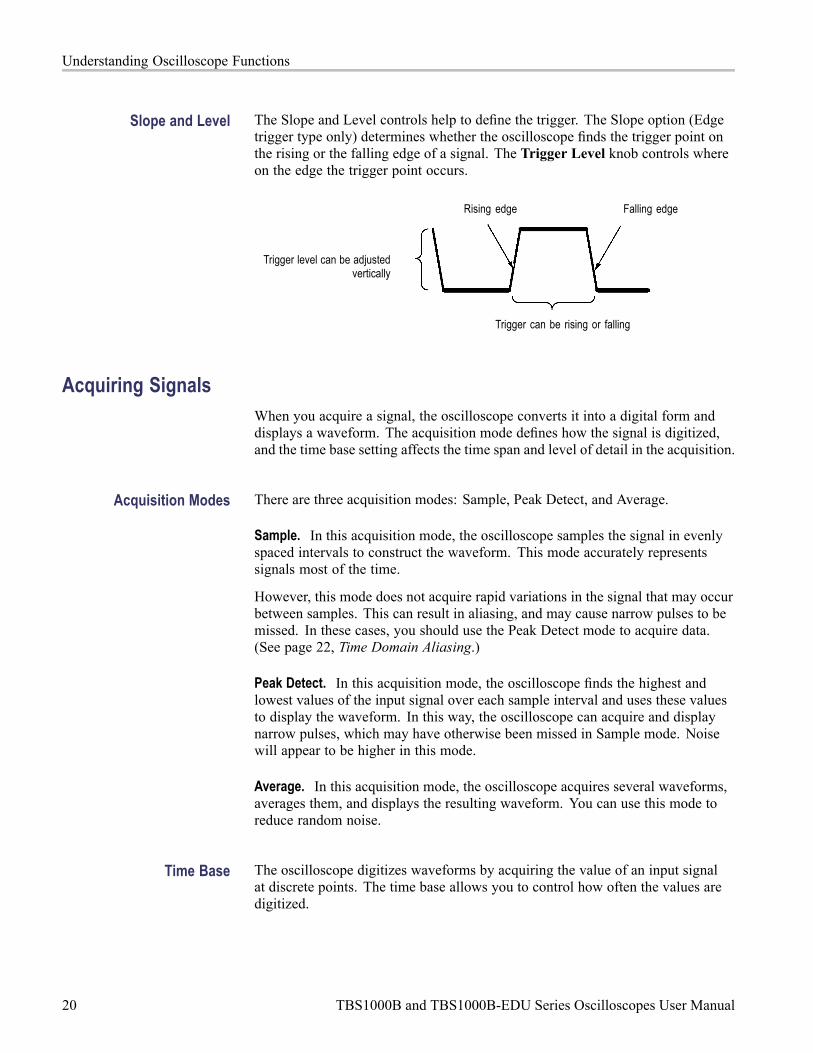
Slope and Level The Slope and Level controls help to define the trigger. The Slope option (Edgetrigger type only) determines whether the oscilloscope finds the trigger point onthe rising or the falling edge of a signal. The Trigger Level knob controls whereon the edge the trigger point occurs.
Rising edge Falling edge
Trigger level can be adjustedvertically
Trigger can be rising or falling
Acquiring SignalsWhen you acquire a signal, the oscilloscope converts it into a digital form anddisplays a waveform. The acquisition mode defines how the signal is digitized,and the time base setting affects the time span and level of detail in the acquisition.
Acquisition Modes There are three acquisition modes: Sample, Peak Detect, and Average.
Sample. In this acquisition mode, the oscilloscope samples the signal in evenlyspaced intervals to construct the waveform. This mode accurately representssignals most of the time.
However, this mode does not acquire rapid variations in the signal that may occurbetween samples. This can result in aliasing, and may cause narrow pulses to bemissed. In these cases, you should use the Peak Detect mode to acquire data.(See page 22, Time Domain Aliasing.)
Peak Detect. In this acquisition mode, the oscilloscope finds the highest andlowest values of the input signal over each sample interval and uses these valuesto display the waveform. In this way, the oscilloscope can acquire and displaynarrow pulses, which may have otherwise been missed in Sample mode. Noisewill appear to be higher in this mode.
Average. In this acquisition mode, the oscilloscope acquires several waveforms,averages them, and displays the resulting waveform. You can use this mode toreduce random noise.
Time Base The oscilloscope digitizes waveforms by acquiring the value of an input signalat discrete points. The time base allows you to control how often the values aredigitized.
20 TBS1000B and TBS1000B-EDU Series Oscilloscopes User Manual

Understanding Oscilloscope Functions
To adjust the time base to a horizontal scale that suits your purpose, use theHorizontal Scale knob.
Scaling and Positioning WaveformsYou can change the display of waveforms by adjusting the scale and position.When you change the scale, the waveform display will increase or decrease in size.When you change the position, the waveform will move up, down, right, or left.
The channel indicator (located on the left of the graticule) identifies eachwaveform on the display. The indicator points to the ground reference level ofthe waveform record.
You can view the display area and readouts. (See page 9, Display Area.)
Vertical Scale and Position You can change the vertical position of waveforms by moving them up or down inthe display. To compare data, you can align a waveform above another or you canalign waveforms on top of each other.
You can change the vertical scale of a waveform. The waveform display willcontract or expand relative to the ground reference level.
For oscilloscope-specific descriptions, refer to the Operating Basics chapter. (Seepage 12, Vertical Controls.) Refer also to the Reference chapter. (See page 106,Vertical Controls.)
Horizontal Scale andPosition; Pretrigger
Information
You can adjust the Horizontal Position control to view waveform data beforethe trigger, after the trigger, or some of each. When you change the horizontalposition of a waveform, you are actually changing the time between the triggerand the center of the display. (This appears to move the waveform to the rightor left on the display.)
For example, if you want to find the cause of a glitch in your test circuit, youmight trigger on the glitch and make the pretrigger period large enough to capturedata before the glitch. You can then analyze the pretrigger data and perhaps findthe cause of the glitch.
You change the horizontal scale of all the waveforms by turning the HorizontalScale knob. For example, you might want to see just one cycle of a waveform tomeasure the overshoot on its rising edge.
The oscilloscope shows the horizontal scale as time per division in the scalereadout. Since all active waveforms use the same time base, the oscilloscope onlydisplays one value for all the active channels, except when you use zoom feature.
For oscilloscope-specific descriptions, refer to the Operating Basics chapter. (Seepage 13, Position.) Refer also to the Reference chapter. (See page 84, Horizontal.)
TBS1000B and TBS1000B-EDU Series Oscilloscopes User Manual 21

Understanding Oscilloscope Functions
Time Domain Aliasing. Aliasing occurs when the oscilloscope does not sample thesignal fast enough to construct an accurate waveform record. When this happens,the oscilloscope displays a waveform with a frequency lower than the actual inputwaveform, or triggers and displays an unstable waveform.
Actual high-frequency waveform
Apparent low-frequencywaveform due to aliasing
Sample points
The oscilloscope accurately represents signals, but is limited by the probebandwidth, the oscilloscope bandwidth, and the sample rate. To avoid aliasing,the oscilloscope must sample the signal more than twice as fast as the highestfrequency component of the signal.
The highest frequency that the oscilloscope sampling rate can theoreticallyrepresent is the Nyquist frequency. The sample rate is called the Nyquist rate, andis twice the Nyquist frequency.
The oscilloscope maximum sample rates are at least ten times the bandwidth.These high sample rates help reduce the possibility of aliasing.
There are several ways to check for aliasing:
Turn the horizontal Scale knob to change the horizontal scale. If the shape ofthe waveform changes drastically, you may have aliasing.
Select the Peak Detect acquisition mode. (See page 20, Peak Detect.) Thismode samples the highest and lowest values so that the oscilloscope candetect faster signals. If the shape of the waveform changes drastically, youmay have aliasing.
If the trigger frequency is faster than the display information, you may havealiasing or a waveform that crosses the trigger level multiple times. Examiningthe waveform allows you to identify whether the shape of the signal is goingto allow a single trigger crossing per cycle at the selected trigger level.
If multiple triggers are likely to occur, select a trigger level that will generateonly a single trigger per cycle. If the trigger frequency is still faster than thedisplay indicates, you may have aliasing.
If the trigger frequency is slower, this test is not useful.
22 TBS1000B and TBS1000B-EDU Series Oscilloscopes User Manual
Understanding Oscilloscope Functions
If the signal you are viewing is also the trigger source, use the graticule or thecursors to estimate the frequency of the displayed waveform. Compare this tothe Trigger Frequency readout in the lower right corner of the screen. If theydiffer by a large amount, you may have aliasing.
Taking MeasurementsThe oscilloscope displays graphs of voltage versus time and can help you tomeasure the displayed waveform.
There are several ways to take measurements. You can use the graticule, thecursors, or an automated measurement.
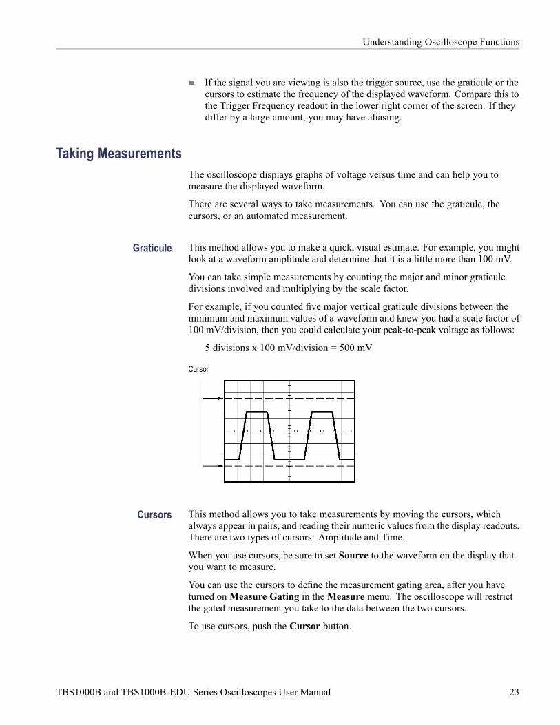
Graticule This method allows you to make a quick, visual estimate. For example, you mightlook at a waveform amplitude and determine that it is a little more than 100 mV.
You can take simple measurements by counting the major and minor graticuledivisions involved and multiplying by the scale factor.
For example, if you counted five major vertical graticule divisions between theminimum and maximum values of a waveform and knew you had a scale factor of100 mV/division, then you could calculate your peak-to-peak voltage as follows:
5 divisions x 100 mV/division = 500 mV
Cursor
Cursors This method allows you to take measurements by moving the cursors, whichalways appear in pairs, and reading their numeric values from the display readouts.There are two types of cursors: Amplitude and Time.
When you use cursors, be sure to set Source to the waveform on the display thatyou want to measure.
You can use the cursors to define the measurement gating area, after you haveturned onMeasure Gating in theMeasure menu. The oscilloscope will restrictthe gated measurement you take to the data between the two cursors.
To use cursors, push the Cursor button.
TBS1000B and TBS1000B-EDU Series Oscilloscopes User Manual 23

Understanding Oscilloscope Functions
Amplitude Cursors. Amplitude cursors appear as horizontal lines on the displayand measure the vertical parameters. Amplitudes are referenced to the referencelevel. For the FFT function, these cursors measure magnitude.
Time Cursors. Time cursors appear as vertical lines on the display and measureboth horizontal and vertical parameters. Times are referenced to the trigger point.For the FFT function, these cursors measure frequency.
Time cursors also include a readout of the waveform amplitude at the point thewaveform crosses the cursor.
Automatic The Measure Menu can take up to six automatic measurements. When youtake automatic measurements, the oscilloscope does all the calculating for you.Because the measurements use the waveform record points, they are moreaccurate than the graticule or cursor measurements.
Automatic measurements use readouts to show measurement results. Thesereadouts are updated periodically as the oscilloscope acquires new data.
For measurement descriptions, refer to the Reference chapter. (See page 85,Taking Measurements.)
24 TBS1000B and TBS1000B-EDU Series Oscilloscopes User Manual

Application ExamplesThis section presents a series of application examples. These simplified exampleshighlight the features of the oscilloscope and give you ideas for using it to solveyour own test problems.
Taking simple measurements
Using Autoset
Using the Measure Menu to take automatic measurements
Measuring two signals and calculating gain
Using Autorange to examine a series of test points
Taking cursor measurements
Measuring ring frequency and ring amplitude
Measuring pulse width
Measuring rise time
Analyzing signal detail
Looking at a noisy signal
Using the average function to separate a signal from noise
Capturing a single-shot signal
Optimizing the acquisition
Measuring propagation delay
Triggering on a pulse width
Triggering on a video signal
Triggering on video fields and video lines
Using the window function to see waveform details
Analyzing a differential communication signal using Math functions
Viewing impedance changes in a network using XY mode and persistence
Data logging (non-EDU models only)
Limit testing (non-EDU models only)
TBS1000B and TBS1000B-EDU Series Oscilloscopes User Manual 25

Application Examples
Taking Simple MeasurementsYou need to see a signal in a circuit, but you do not know the amplitude orfrequency of the signal. You want to quickly display the signal and measure thefrequency, period, and peak-to-peak amplitude.
Using Autoset To quickly display a signal, follow these steps:
1. Push the 1 (channel 1 menu) button.
2. Push Probe VoltageAttenuation 10X.
3. If using P2220 probes, set their switches to 10X.
4. Connect the channel 1 probe tip to the signal. Connect the reference lead tothe circuit reference point.
5. Push the Autoset button.
The oscilloscope sets the vertical, horizontal, and trigger controls automatically.If you want to optimize the display of the waveform, you can manually adjustthese controls.
NOTE. The oscilloscope displays relevant automatic measurements in thewaveform area of the screen based on the signal type that is detected.
For oscilloscope-specific descriptions, refer to the Reference chapter. (Seepage 73, Autoset.)
26 TBS1000B and TBS1000B-EDU Series Oscilloscopes User Manual
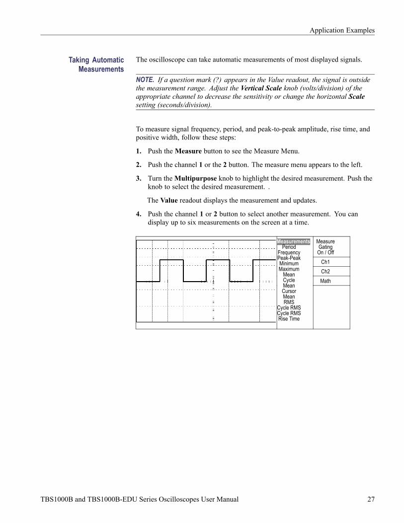
Application Examples
Taking AutomaticMeasurements
The oscilloscope can take automatic measurements of most displayed signals.
NOTE. If a question mark (?) appears in the Value readout, the signal is outsidethe measurement range. Adjust the Vertical Scale knob (volts/division) of theappropriate channel to decrease the sensitivity or change the horizontal Scalesetting (seconds/division).
To measure signal frequency, period, and peak-to-peak amplitude, rise time, andpositive width, follow these steps:
1. Push theMeasure button to see the Measure Menu.
2. Push the channel 1 or the 2 button. The measure menu appears to the left.
3. Turn theMultipurpose knob to highlight the desired measurement. Push theknob to select the desired measurement. .
The Value readout displays the measurement and updates.
4. Push the channel 1 or 2 button to select another measurement. You candisplay up to six measurements on the screen at a time.
MeasureGating
On / Off
Ch1
Ch2
Math
MeasurementsPeriod
FrequencyPeak-PeakMinimumMaximum
MeanCycleMeanCursorMeanRMS
Cycle RMSCycle RMSRise Time
TBS1000B and TBS1000B-EDU Series Oscilloscopes User Manual 27

Application Examples
Measuring Two Signals If you are testing a piece of equipment and need to measure the gain of the audioamplifier, you will need an audio generator that can inject a test signal at theamplifier input. Connect two oscilloscope channels to the amplifier input andoutput as shown next. Measure both signal levels and use the measurements tocalculate the gain.
MeasureGatingOn-Off
Ch1
Ch2
Math
To activate and display the signals connected to channel 1 and to channel 2, andselect measurements for the two channels, follow these steps:
1. Push the Autoset button.
2. Push theMeasure button to see the Measure Menu.
3. Push the Ch1 side menu. The pop-up menu of measurement types appears tothe left.
4. Turn theMultipurpose knob to highlight Peak-Peak.
5. Push theMultipurpose knob to select Peak-Peak. A check should appearnext to the menu item and the Peak-to-Peak measurement for channel 1should appear towards the bottom of the display.
28 TBS1000B and TBS1000B-EDU Series Oscilloscopes User Manual

Application Examples
6. Push the Ch1 side menu. The pop-up menu of measurement types appearsto the left. .
7. Turn theMultipurpose knob to highlight Peak-Peak.
8. Push theMultipurpose knob to select Peak-Peak. A check should appearnext to the menu item and the peak-to-peak for channel 2 should appeartowards the bottom of the display.
9. Read the displayed peak-to-peak amplitudes for both channels.
10. To calculate the amplifier voltage gain, use these equations:
VoltageGain = output amplitude/input amplitude
VoltageGain (dB) = 20 × log 10 (VoltageGain)
TBS1000B and TBS1000B-EDU Series Oscilloscopes User Manual 29

Application Examples
Using Autorange to Examine a Series of Test PointsIf you have a machine that is malfunctioning, you may need to find the frequencyand RMS voltage of several test points, and compare these values to ideal values.You are not able to access front-panel controls since you need to use both handswhen probing test points that are difficult to physically reach.
1. Push the 1 (channel 1 menu) button.
2. Push Probe Voltage Attenuation. Chose the attenuation of the probeattached to channel 1 from the pop-out selectable list of values by turningand pushing theMultipurpose knob.
3. Push the Autoset button for more than 1.5 seconds to activate autoranging,and select the Vertical and Horizontal option.
4. Push theMeasure button to see the Measure Menu.
5. Push Ch1.
6. Turn theMultipurpose knob to select Frequency.
7. Push Ch2.
8. Turn theMultipurpose knob to select Cycle RMS.
9. Attach the probe tip and reference lead to the first test point. Read thefrequency and cycle RMS measurements from the oscilloscope display andcompare these to the ideal values.
10. Repeat the preceding step for each test point, until you find the malfunctioningcomponent.
NOTE. When Autorange is active, each time you move the probe to another testpoint, the oscilloscope readjusts the horizontal scale, the vertical scale, and thetrigger level, to give you a useful display.
Taking Cursor MeasurementsYou can use the cursors to quickly take time and amplitude measurements ona waveform.
Measuring Ring Frequencyand Amplitude
To measure the ring frequency at the rising edge of a signal, follow these steps:
1. Push the Cursor front-panel button to see the Cursor Menu.
2. Push the Type side-menu button. A pop-out menu should appear showing ascroll-able list of the available cursor types.
3. Turn theMultipurpose knob to highlight Time.
4. Push theMultipurpose knob to select Time.
30 TBS1000B and TBS1000B-EDU Series Oscilloscopes User Manual

Application Examples
5. Push the Source side-menu button. A pop-out menu should appear showing ascroll-able list of the available sources.
6. Turn theMultipurpose knob to highlight Ch1.
7. Push theMultipurpose knob to select Ch1.
8. Push the Cursor 1 option button.
9. Turn the multipurpose knob to place a cursor on the first peak of the ring.
10. Push the Cursor 2 option button.
11. Turn the multipurpose knob to place a cursor on the second peak of the ring.
You can see the Δ (delta) time and frequency (the measured ring frequency)in the Cursor Menu.
TypeTime
SourceCh1
Δt 540.0ns1/Δt
1.852MHzΔV 0.44V
Cursor1180ns1.40V
Cursor2720ns0.96V
12. Push the Type side-menu button. A pop-out menu should appear showing ascroll-able list of the available cursor types.
13. Turn theMultipurpose knob to highlight Amplitude.
14. Push theMultipurpose knob to select Amplitude.
15. Push the Cursor 1 option button.
16. Turn the multipurpose knob to place a cursor on the first peak of the ring.
17. Push the Cursor 2 option button.
18. Turn the multipurpose knob to place Cursor 2 on the lowest part of the ring.
You can see the amplitude of the ring in the Cursor Menu.
TBS1000B and TBS1000B-EDU Series Oscilloscopes User Manual 31

Application Examples
TypeAmplitude
SourceCh1
ΔV 640mV
Cursor 11.46V
Cursor 2820mV
Measuring Pulse Width If you are analyzing a pulse waveform and you want to know the width of thepulse, follow these steps:
1. Push the Cursor button to see the Cursor Menu.
2. Push the Type side-menu button. A pop-out menu should appear showing ascroll-able list of the available cursor types.
3. Turn theMultipurpose knob to highlight Time.
4. Push theMultipurpose knob to select Time.
5. Push the Cursor 1 option button.
6. Turn the multipurpose knob to place a cursor on the rising edge of the pulse.
7. Push the Cursor 2 option button.
8. Turn the multipurpose knob to place a cursor on the falling edge of the pulse.
You can see the following measurements in the Cursor Menu:
The time at Cursor 1, relative to the trigger.
The time at Cursor 2, relative to the trigger.
The Δ (delta) time, which is the pulse width measurement.
32 TBS1000B and TBS1000B-EDU Series Oscilloscopes User Manual

Application Examples
TypeTime
SourceCh1
Δt 500.0µs1/Δt 2.000kHzΔV 1.38V
Cursor 10.00s0.98V
Cursor 2500µs-1.00V
NOTE. The Positive Width measurement is available as an automatic measurementin the Measure Menu. (See page 85, Taking Measurements.)
NOTE. The Positive Width measurement also displays when you select theSingle-Cycle Square option in the Autoset Menu. (See page 75, Square Waveor Pulse.)
Measuring Rise Time After measuring the pulse width, you decide that you need to check the rise timeof the pulse. Typically, you measure rise time between the 10% and 90% levels ofthe waveform. To measure the rise time, follow these steps:
1. Turn the Horizontal Scale (seconds/division) knob to display the rising edgeof the waveform.
2. Turn the Vertical Scale (volts/division) and Vertical Position knobs to setthe waveform amplitude to about five divisions.
3. Push the 1 (channel 1 menu) button.
4. Push Volts/Div Fine.
5. Turn the Vertical Scale (volts/division) knob to set the waveform amplitudeto exactly five divisions.
6. Turn the Vertical Position knob to center the waveform; position the baselineof the waveform 2.5 divisions below the center graticule.
7. Push the Cursor button to see the Cursor Menu.
8. Push the Type side-menu button. A pop-out menu should appear showing ascroll-able list of the available cursor types.
9. Turn theMultipurpose knob to highlight Time.
10. Push theMultipurpose knob to select Time.
TBS1000B and TBS1000B-EDU Series Oscilloscopes User Manual 33

Application Examples
11. Push the Source side-menu button. A pop-out menu should appear showing ascroll-able list of the available sources.
12. Turn theMultipurpose knob to highlight Ch1.
13. Push theMultipurpose knob to select Ch1.
14. Push the Cursor 1 option button.
15. Turn the multipurpose knob to place a cursor at the point where the waveformcrosses the second graticule line below center screen. This is the 10% levelof the waveform.
16. Push the Cursor 2 option button.
17. Turn the multipurpose knob to place a cursor at the point where the waveformcrosses the second graticule line above center screen. This is the 90% levelof the waveform.
The Δt readout in the Cursor Menu is the rise time of the waveform.
5 divisions
TypeTime
SourceCh1
Δt 140.0ns1/Δt
7.143MHzΔV 2.08V
Cursor 1-80.0ns-1.02V
Cursor 260.0ns1.06V
NOTE. The Rise Time measurement is available as an automatic measurement inthe Measure Menu. (See page 85, Taking Measurements.)
NOTE. The Rise Time measurement also displays when you select the Rising Edgeoption in the Autoset Menu. (See page 75, Square Wave or Pulse.)
34 TBS1000B and TBS1000B-EDU Series Oscilloscopes User Manual
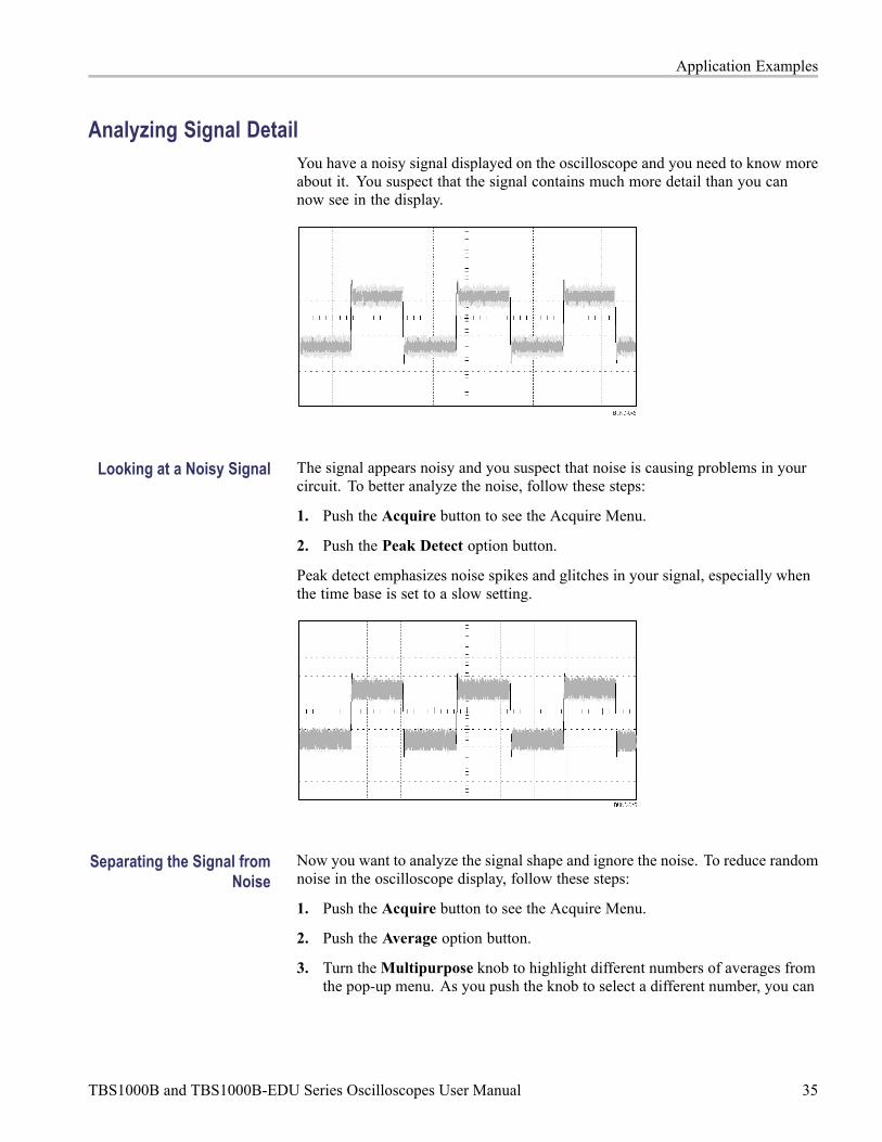
Application Examples
Analyzing Signal DetailYou have a noisy signal displayed on the oscilloscope and you need to know moreabout it. You suspect that the signal contains much more detail than you cannow see in the display.
Looking at a Noisy Signal The signal appears noisy and you suspect that noise is causing problems in yourcircuit. To better analyze the noise, follow these steps:
1. Push the Acquire button to see the Acquire Menu.
2. Push the Peak Detect option button.
Peak detect emphasizes noise spikes and glitches in your signal, especially whenthe time base is set to a slow setting.
Separating the Signal fromNoise
Now you want to analyze the signal shape and ignore the noise. To reduce randomnoise in the oscilloscope display, follow these steps:
1. Push the Acquire button to see the Acquire Menu.
2. Push the Average option button.
3. Turn theMultipurpose knob to highlight different numbers of averages fromthe pop-up menu. As you push the knob to select a different number, you can
TBS1000B and TBS1000B-EDU Series Oscilloscopes User Manual 35

Application Examples
see the effects of varying the number of running averages on the waveformdisplay.
Averaging reduces random noise and makes it easier to see detail in a signal. Inthe example below, a ring shows on the rising and falling edges of the signal whenthe noise is removed.
Capturing a Single-Shot SignalThe reliability of a reed relay in a piece of equipment has been poor and you needto investigate the problem. You suspect that the relay contacts arc when the relayopens. The fastest that you can open and close the relay is about once per minute,so you need to capture the voltage across the relay as a single-shot acquisition.
To set up for a single-shot acquisition, follow these steps:
1. Turn the Vertical Scale (volts/division) and Horizontal Scale(seconds/division) knobs to the appropriate ranges for the signal you expect tosee.
2. Push the Acquire button to see the Acquire Menu.
3. Push the Peak Detect option button.
4. Push the Trigger Menu button to see the Trigger Menu.
5. Push Slope.
6. Turn theMultipurpose knob to highlight Rising from the pop-out menu.Push the knob to select the choice
7. Turn the front-panel Level knob to adjust the trigger level to a voltage midwaybetween the open and closed voltages of the relay.
8. Push the Single button to start the acquisition.
When the relay opens, the oscilloscope triggers and captures the event.
36 TBS1000B and TBS1000B-EDU Series Oscilloscopes User Manual
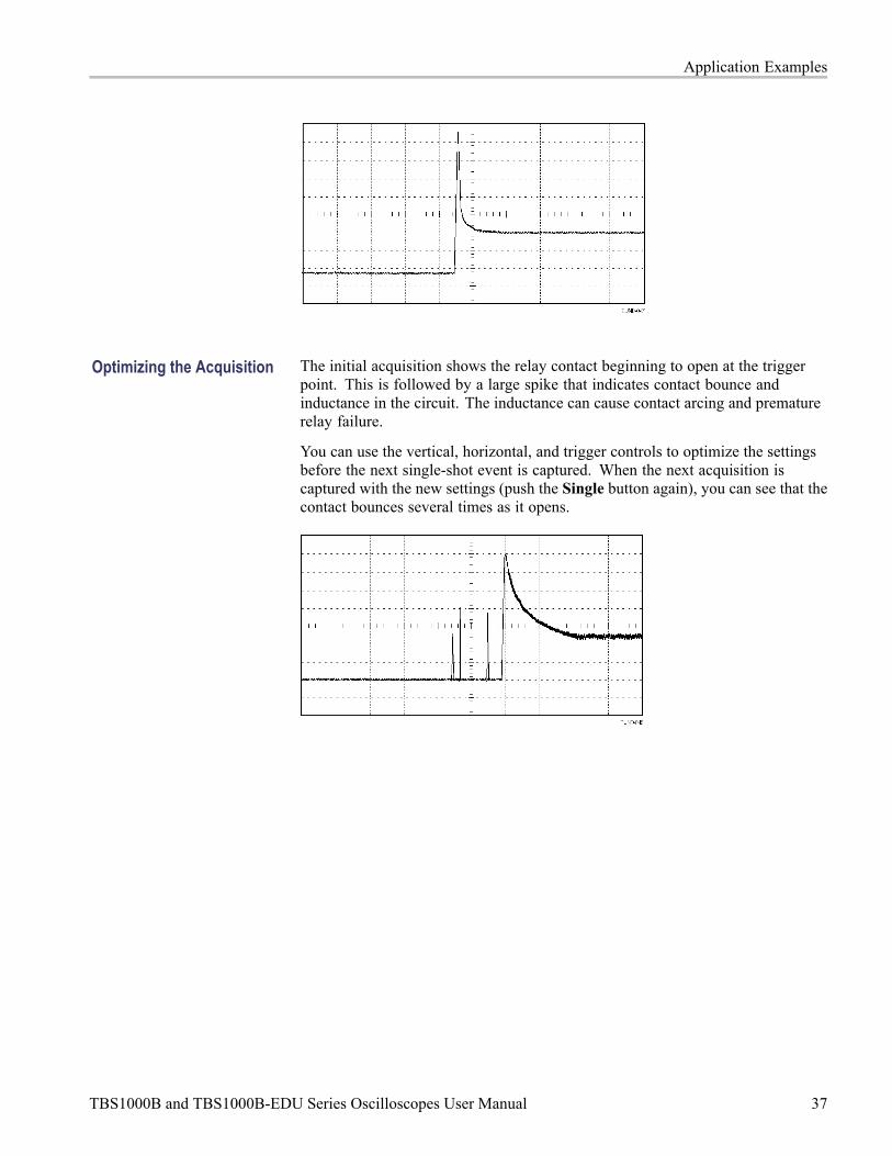
Application Examples
Optimizing the Acquisition The initial acquisition shows the relay contact beginning to open at the triggerpoint. This is followed by a large spike that indicates contact bounce andinductance in the circuit. The inductance can cause contact arcing and prematurerelay failure.
You can use the vertical, horizontal, and trigger controls to optimize the settingsbefore the next single-shot event is captured. When the next acquisition iscaptured with the new settings (push the Single button again), you can see that thecontact bounces several times as it opens.
TBS1000B and TBS1000B-EDU Series Oscilloscopes User Manual 37

Application Examples
Measuring Propagation DelayYou suspect that the memory timing in a microprocessor circuit is marginal. Setup the oscilloscope to measure the propagation delay between the chip-selectsignal and the data output of the memory device.
TypeTime
SourceCh1
Δt 20.00ns1/Δt
50.00MHzΔV 0.28V
Cursor 150.0ns-0.20V
Cursor 270.0ns0.08V
To set up to measure propagation delay, follow these steps:
1. Push the Autoset button to trigger a stable display.
2. Adjust the horizontal and vertical controls to optimize the display.
3. Push the Cursor button to see the Cursor Menu.
4. Push the Type side-menu button. A pop-out menu should appear showing ascroll-able list of the available cursor types.
5. Turn theMultipurpose knob to highlight Time.
6. Push theMultipurpose knob to select Time.
7. Push the Source side-menu button. A pop-out menu should appear showing ascroll-able list of the available sources.
38 TBS1000B and TBS1000B-EDU Series Oscilloscopes User Manual

Application Examples
8. Turn theMultipurpose knob to highlight Ch1.
9. Push theMultipurpose knob to select Ch1.
10. Push the Cursor 1 option button.
11. Push the Cursor 1 option button.
12. Turn the multipurpose knob to place a cursor on the active edge of thechip-select signal.
13. Push the Cursor 2 option button.
14. Turn the multipurpose knob to place the second cursor on the data outputtransition.
The Δt readout in the Cursor Menu is the propagation delay between thewaveforms. The readout is valid because the two waveforms have the samehorizontal scale (seconds/division) setting.
Triggering on a Specific Pulse Width
To set up a test for pulse width aberrations, follow these steps:
1. Push the Autoset button to trigger a stable display.
2. Push the single cycle option button in the Autoset Menu to view asingle cycle of the signal, and to quickly take a Pulse Width measurement.
3. Push the Trigger Menu button to see the Trigger Menu.
4. Push Type.
5. Turn theMultipurpose knob to highlight Pulse from the pop-out menu. Pushthe knob to select the choice
6. Push Source.
7. Turn theMultipurpose knob to highlight Ch1 from the pop-out menu. Pushthe knob to select the choice
TBS1000B and TBS1000B-EDU Series Oscilloscopes User Manual 39

Application Examples
8. Turn the trigger Level knob to set the trigger level near the bottom of thesignal.
9. PushWhen = (equals).
10. Push Pulse Width.
11. Turn the multipurpose knob to set the pulse width to the value reported by thePulse Width measurement in step 2.
12. PushMoreMode Normal.
You can achieve a stable display with the oscilloscope triggering on normal pulses.
1. Push theWhen option button to select ≠, <, or >. If there are any aberrantpulses that meet the specified When condition, the oscilloscope triggers.
NOTE. The trigger frequency readout shows the frequency of events that theoscilloscope might consider to be a trigger, and may be less than the frequency ofthe input signal in Pulse Width trigger mode.
40 TBS1000B and TBS1000B-EDU Series Oscilloscopes User Manual

Application Examples
Triggering on a Video SignalYou are testing the video circuit in a piece of medical equipment and need todisplay the video output signal. The video output is an NTSC standard signal. Usethe video trigger to obtain a stable display.
NOTE. Most video systems use 75 ohm cabling. The oscilloscope inputs do notproperly terminate low impedance cabling. To avoid amplitude inaccuracyfrom improper loading and reflections, place a 75 ohm feedthrough terminator(Tektronix part number 011-0055-02 or equivalent) between the 75 ohm coaxialcable from the signal source and the oscilloscope BNC input.
Triggering on Video Fields Automatic. To trigger on the video fields, follow these steps:
1. Push the Autoset button. When Autoset is complete, the oscilloscope displaysthe video signal with sync on All Fields.
The oscilloscope sets the Standard option when you use the Autoset function.
1. Push the Odd Field or Even Field option buttons from the Autoset Menuto sync on odd or even fields only.
Manual. An alternative method requires more steps, but may be necessarydepending on the video signal. To use the manual method, follow these steps:
TBS1000B and TBS1000B-EDU Series Oscilloscopes User Manual 41

Application Examples
1. Push the 1 (channel 1 menu) button.
2. Push Coupling AC.
3. Push the Trigger Menu button to see the Trigger Menu.
4. Push the top option button and select Video.
5. Push Source Ch1.
6. Push the Sync option button and select All Fields, Odd Field, or Even Field.
7. On page 2 of the side menu, push Standard NTSC.
8. Turn the Horizontal Scale (seconds/division) knob to see a complete fieldacross the screen.
9. Turn the Vertical Scale (volts/division) knob to ensure that the entire videosignal is visible on the screen.
42 TBS1000B and TBS1000B-EDU Series Oscilloscopes User Manual

Application Examples
Triggering on Video Lines Automatic. You can also look at the video lines in the field. To trigger on thevideo lines, follow these steps:
1. Push the Autoset button.
2. Push the top option button to select Line to sync on all lines. (The AutosetMenu includes All Lines and Line Number options.)
Manual. An alternative method requires more steps, but may be necessarydepending on the video signal. To use this method, follow these steps:
1. Push the Trigger Menu button to see the Trigger Menu.
2. Push the top option button and select Video.
3. Push the Sync option button and select All Lines or Line Number and turnthe multipurpose knob to set a specific line number.
4. Push Standard NTSC.
5. Turn the Horizontal Scale (seconds/division) knob to see a complete videoline across the screen.
6. Turn the Vertical Scale (volts/division) knob to ensure that the entire videosignal is visible on the screen.
Incoming video signal
TBS1000B and TBS1000B-EDU Series Oscilloscopes User Manual 43
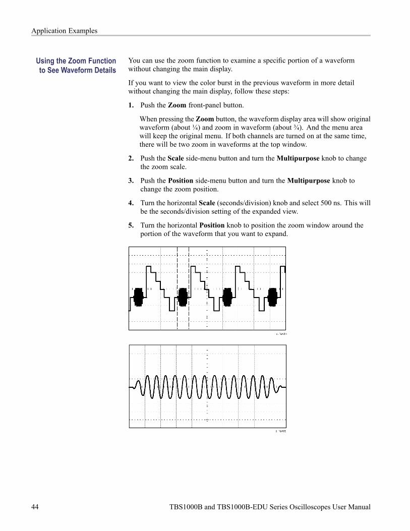
Application Examples
Using the Zoom Functionto See Waveform Details
You can use the zoom function to examine a specific portion of a waveformwithout changing the main display.
If you want to view the color burst in the previous waveform in more detailwithout changing the main display, follow these steps:
1. Push the Zoom front-panel button.
When pressing the Zoom button, the waveform display area will show originalwaveform (about ¼) and zoom in waveform (about ¾). And the menu areawill keep the original menu. If both channels are turned on at the same time,there will be two zoom in waveforms at the top window.
2. Push the Scale side-menu button and turn theMultipurpose knob to changethe zoom scale.
3. Push the Position side-menu button and turn theMultipurpose knob tochange the zoom position.
4. Turn the horizontal Scale (seconds/division) knob and select 500 ns. This willbe the seconds/division setting of the expanded view.
5. Turn the horizontal Position knob to position the zoom window around theportion of the waveform that you want to expand.
44 TBS1000B and TBS1000B-EDU Series Oscilloscopes User Manual

Application Examples
Analyzing a Differential Communication SignalYou are having intermittent problems with a serial data communication link, andyou suspect poor signal quality. Set up the oscilloscope to show you a snapshot ofthe serial data stream so you can verify the signal levels and transition times.
Because this is a differential signal, you use the Math function of the oscilloscopeto view a better representation of the waveform.
NOTE. Be sure to first compensate both probes. Differences in probecompensation appear as errors in the differential signal.
To activate the differential signals connected to channel 1 and to channel 2,follow these steps:
1. Push the 1 (channel 1 menu) button and set the Probe Voltage Attenuation option to 10X.
2. Push the 2 (channel 2 menu) button and set the Probe Voltage Attenuation option to 10X.
TBS1000B and TBS1000B-EDU Series Oscilloscopes User Manual 45

Application Examples
3. If using P2220 probes, set their switches to 10X.
4. Push the Autoset button.
5. Push theMath button to see the Math Menu.
6. Push the Operation option button and select -.
7. Push the Sources Ch1-Ch2 option button to display a new waveform that isthe difference between the displayed waveforms.
8. To adjust the vertical scale and position of the Math waveform, follow thesesteps:
a. Remove the channel 1 and channel 2 waveforms from the display.
b. Turn the channel 1 and channel 2 Vertical Scale and Vertical Positionknobs to adjust the vertical scale and position of the Math waveform.
For a more stable display, push the Single button to control the acquisition ofthe waveform. Each time you push the Single button, the oscilloscope acquiresa snapshot of the digital data stream. You can use the cursors or automaticmeasurements to analyze the waveform, or you can store the waveform to analyzelater.
Viewing Impedance Changes in a NetworkYou have designed a circuit that needs to operate over a wide temperature range.You need to evaluate the change in impedance of the circuit as the ambienttemperature is changed.
Connect the oscilloscope to monitor the input and output of the circuit and capturethe changes that occur as you vary the temperature.
46 TBS1000B and TBS1000B-EDU Series Oscilloscopes User Manual

Application Examples
To view the input and output of the circuit in an XY display, follow these steps:
1. Push the 1 (channel 1 menu) button.
2. Push Probe VoltageAttenuation 10X.
3. Push the 2 (channel 2 menu) button.
4. Push Probe Voltage Attenuation 10X.
5. If using P2220 probes, set their switches to 10X.
6. Connect the channel 1 probe to the input of the network, and connect thechannel 2 probe to the output.
7. Push the Autoset button.
8. Turn the Vertical Scale (volts/division) knobs to display approximately thesame amplitude signals on each channel.
9. Push the Utility Display button to see the Display Menu.
10. Push Format XY.
TBS1000B and TBS1000B-EDU Series Oscilloscopes User Manual 47

Application Examples
The oscilloscope displays a Lissajous pattern representing the input andoutput characteristics of the circuit.
11. Turn the vertical Scale and vertical Position knobs to optimize the display.
12. Push Persist Infinite.
As you adjust the ambient temperature, the display persistence captures thechanges in the characteristics of the circuit.
Data Logging (non-EDU models only)You can use the oscilloscope to record data from a source over time. You canconfigure the trigger conditions and direct the oscilloscope to save all the triggeredwaveform together with timing information over a defined time duration to aUSB memory device.
The USB host port on the front panel supports data logging. You can set up theoscilloscope to save user- specified triggered waveforms to a USB device for upto 24 hours. You can also select the "Infinite" option for continuous waveformmonitoring. In the infinite mode you can save your triggered waveforms to anexternal USB memory device without a duration limitation until the memorydevice is full. The oscilloscope will then guide you to insert another USB memorydevice to continue saving waveforms.
1. Configure the oscilloscope to use the desired trigger conditions to collect thedata. Also, insert a USB memory device in the front-panel USB port.
2. Push the front-panel Function button.
3. Select Data Logging from the resulting side menu to bring up the datalogging menu.
4. Push Data Logging from the side menu to select On. This enables the datalogging feature. Before turning on the data logging feature, you must firstselect the source, the time duration, and the folder.
5. Push the Source button to select the signal source to log data from. You canuse either one of the input channels or the Math waveform.
6. Push the Duration button as many times as needed or use the multipurposeknob to select the duration for data logging. The selections range from 0.5hour to 8 hours in 30 minute increments and from 8 hours to 24 hours in60 minute increments. You can select Infinite to run data logging with noset time limit.
7. Push the Select Folder button to define where to store the collectedinformation. The resulting menu choices will let you either select an existingfolder or define a new folder. When done, push Back to return to the maindata logging menu
48 TBS1000B and TBS1000B-EDU Series Oscilloscopes User Manual
Application Examples
8. Start the data acquisition, such as by pushing either the front-panel Singleor Run/Stop button.
9. When the oscilloscope finishes the requested data logging operation, itdisplays a “Data logging completed” message and turns off the data loggingfeature.
Limit Testing (non-EDU models only)You can use the oscilloscope to monitor an active input signal against a templateand to output pass or fail results by judging whether the input signal is within thebounds of the template.
Use the limit test if you need a Pass/Fail test to determine if a signal is good. Setup the oscilloscope to automatically monitor a source signals and output Passor Fail results by evaluating whether or not the acquired waveform falls withinpredefined boundaries. The limit test feature allows you to create templates basedon one or two independent reference waveforms. If a failure is detected, a seriesof specific actions can be triggered.
1. Push the front-panel Function button.
2. Select Limit Test from the resulting side menu to bring up the limit testingmenu.
3. Select Source from the side menu to define the source of the waveform tocompare against the limit test template.
4. Select Compare To to specify the limit test template against which tocompare test signals sectioned with the Source menu item.
5. Push Template Setup from the side menu to define the boundary to comparewith the input source signals. You can create the template with specifichorizontal and vertical tolerances. You can create them from channel 1,channel 2, or the Math waveform.
6. Push Display Template and toggle between On and Off to display or not astored template.
7. Push the Action on Violation button and select an action from the resultingmenu to describe what the oscilloscope will do after it detects a violation. Youcan select between Save Waveform and Save Image.
8. Push the Stop After button and toggle the resulting button with the samename to define the conditions that will stop limit testing. SelectWaveforms,Violations, or Time and use the multipurpose knob to set the desired numberof waveforms, number of violations, or the time in seconds at which to stop.You can also choose to stop the testing manually.
9. Push the Run/Stop Test button to toggle between starting and ending the limittest. After you end the test, the oscilloscope will display the test statistics on
TBS1000B and TBS1000B-EDU Series Oscilloscopes User Manual 49

Application Examples
the screen. This includes the number of cases tested, the number of casespassed, and the number of cases failed.
50 TBS1000B and TBS1000B-EDU Series Oscilloscopes User Manual

FFTFFT converts a time-domain (YT) signal into its frequency components(spectrum). The oscilloscope can optionally display the source waveform at thesame time as the FFT waveform. Use FFT for the following types of analysis:
Analyze harmonics in power lines
Measure harmonic content and distortion in systems
Characterize noise in DC power supplies
Test impulse response of filters and systems
Analyze vibration
To use FFT, you need to perform the following tasks:
Set up the source (time-domain) waveform
Display the FFT spectrum
Select a type of FFT window
Adjust the sample rate to display the fundamental frequency and harmonicswithout aliasing
Use cursors to measure the spectrum
Setting Up the Time-Domain WaveformBefore you use FFT, you need to set up the time-domain (YT) waveform. To doso, follow these steps:
1. Push Autoset to display a YT waveform.
2. Turn the vertical Position knob to move the YT waveform to the centervertically (zero divisions).
This ensures that the FFT will show a true DC value.
3. Turn the Horizontal Position knob to position the part of the YT waveformthat you want to analyze in the center eight divisions of the screen.
The oscilloscope calculates the FFT spectrum using the center 2048 points ofthe time-domain waveform.
TBS1000B and TBS1000B-EDU Series Oscilloscopes User Manual 51
FFT
4. Turn the Vertical Scale (volts/division) knob to ensure that the entirewaveform remains on the screen. The oscilloscope may display erroneousFFT results (by adding high frequency components) if the entire waveform isnot visible.
5. Turn the Horizontal Scale (seconds/division) knob to provide the resolutionyou want in the FFT spectrum.
6. If possible, set the oscilloscope to display many signal cycles.
If you turn the horizontal Scale knob to select a faster setting (fewer cycles),the FFT spectrum shows a larger frequency range, and reduces the possibilityof FFT aliasing. (See page 55, FFT Aliasing.) However, the oscilloscope alsodisplays less frequency resolution.
To set up the FFT display, follow these steps:
1. Push the FFT front-panel button to see the FFT side menu.
2. Push Source from the side menu.
3. Turn theMultipurpose knob to highlight the source channel. Push the knobto select the channel.
In many cases, the oscilloscope can produce a useful FFT spectrum even if theYT waveform is not triggered. This is especially true if your signal is periodicor random (noisy).
NOTE. Trigger and position any transient or burst waveforms as closely aspossible to the center of the screen.
Nyquist Frequency The highest frequency that any real-time digitizing oscilloscope can measurewithout errors is one-half the sample rate. This frequency is called the Nyquistfrequency. Frequency information above the Nyquist frequency is undersampled,which causes FFT aliasing. (See page 55, FFT Aliasing.)
The math function transforms the center 2048 points of the time-domainwaveform into an FFT spectrum. The resulting FFT spectrum contains 1024points that go from DC (0 Hz) to the Nyquist frequency.
Normally, the display compresses the FFT spectrum horizontally into 250 points,but you can use the FFT Zoom function to expand the FFT spectrum to moreclearly see the frequency components at each of the 1024 data points in the FFTspectrum.
NOTE. The oscilloscope vertical response rolls off slowly above its bandwidth(40 MHz, 60 MHz, 100 MHz or 200 MHz, depending on the model, or 20 MHzwhen the Bandwidth Limit option is ON). Therefore, the FFT spectrum can showvalid frequency information higher than the oscilloscope bandwidth. However, themagnitude information near or above the bandwidth will not be accurate.
52 TBS1000B and TBS1000B-EDU Series Oscilloscopes User Manual

FFT
Displaying the FFT SpectrumPush the FFT button to display the FFT side menu. Use the options to select theSource channel, Window algorithm, and FFT Zoom factor. You can display onlyone FFT spectrum at a time.
FFT option Settings Comments
Source On/Off On, Off Selects whether the screen displays the source waveformat the same time as it displays the FFT waveform
Source Ch1, Ch2 Selects the channel used as the FFT source
Window Hanning, Flattop, Rectangular Selects the FFT window type; (See page 54, Selectingan FFT Window.)
FFT Zoom X1, X2, X5, X10 Changes the horizontal magnification of the FFT display;(See page 57, Magnifying and Positioning an FFTSpectrum.)
1. Frequency at the center graticule line.
2. Vertical scale in dB per division (0 dB = 1 VRMS).
3. Horizontal scale in frequency per division.
4. Sample rate in number of samples per second.
5. FFT window type.
TBS1000B and TBS1000B-EDU Series Oscilloscopes User Manual 53
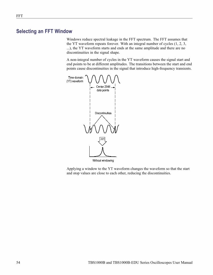
FFT
Selecting an FFT WindowWindows reduce spectral leakage in the FFT spectrum. The FFT assumes thatthe YT waveform repeats forever. With an integral number of cycles (1, 2, 3,...), the YT waveform starts and ends at the same amplitude and there are nodiscontinuities in the signal shape.
A non-integral number of cycles in the YT waveform causes the signal start andend points to be at different amplitudes. The transitions between the start and endpoints cause discontinuities in the signal that introduce high-frequency transients.
Applying a window to the YT waveform changes the waveform so that the startand stop values are close to each other, reducing the discontinuities.
54 TBS1000B and TBS1000B-EDU Series Oscilloscopes User Manual

FFT
The FFT function includes three FFT Window options. There is a trade-offbetween frequency resolution and amplitude accuracy with each type of window.What you want to measure and your source signal characteristics will help you todetermine which window to use.
Window Measure Characteristics
Hanning Periodic waveforms Better frequency, poorer magnitudeaccuracy than Flattop
Flattop Periodic waveforms Better magnitude, poorer frequencyaccuracy than Hanning
Rectangular Pulses or transients Special-purpose window for waveformsthat do not have discontinuities. This isessentially the same as no window
FFT Aliasing Problems occur when the oscilloscope acquires a time-domain waveformcontaining frequency components that are greater than the Nyquist frequency.(See page 52, Nyquist Frequency.) The frequency components that are above theNyquist frequency are undersampled, appearing as lower frequency componentsthat "fold back" around the Nyquist frequency. These incorrect components arecalled aliases.
TBS1000B and TBS1000B-EDU Series Oscilloscopes User Manual 55
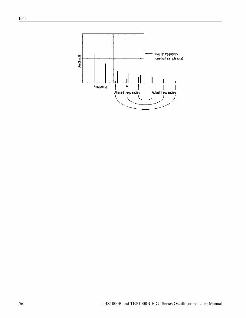
FFT
56 TBS1000B and TBS1000B-EDU Series Oscilloscopes User Manual

FFT
Eliminating Aliases To eliminate aliases, try the following remedies:
Turn the Horizontal Scale (seconds/division) knob to set the sample rate toa faster setting. Since you increase the Nyquist frequency as you increasethe sample rate, the aliased frequency components appear at their properfrequency. If too many frequency components are shown on the screen, youcan use the FFT Zoom option to magnify the FFT spectrum.
If you do not need to view frequency components above 20 MHz, set theBandwidth Limit option to On.
Put an external filter on the source signal to bandwidth limit the sourcewaveform to frequencies below that of the Nyquist frequency.
Recognize and ignore the aliased frequencies.
Use zoom controls and the cursors to magnify and measure the FFT spectrum.
Magnifying and Positioning an FFT SpectrumYou can magnify and use cursors to take measurements on the FFT spectrum. Theoscilloscope includes an FFT Zoom option to magnify horizontally. To magnifyvertically, you can use the vertical controls.
Horizontal Zoom andPosition
The FFT Zoom option lets you horizontally magnify the FFT spectrum withoutchanging the sample rate. Zoom factors are X1 (default), X2, X5, and X10. Atzoom factor X1, and with the waveform centered in the graticule, the left graticuleline is at 0 Hz and the right graticule line is at the Nyquist frequency.
When you change the zoom factor, the FFT spectrum is magnified about thecenter graticule line. In other words, the axis of horizontal magnification is thecenter graticule line.
Turn the Horizontal Position knob clockwise to move the FFT spectrum to theright. Push the Set To Zero button to position the center of the spectrum at thecenter of the graticule.
Vertical Zoom and Position The channel vertical knobs become vertical zoom and position controls for theirrespective channels when displaying the FFT spectrum. The Vertical Scaleknob provides zoom factors of X0.5, X1 (default), X2, X5, and X10. The FFTspectrum is vertically magnified about the M marker (math waveform referencepoint on the left edge of the screen).
Turn the Vertical Position knob clockwise to move the spectrum up for thesource channel.
TBS1000B and TBS1000B-EDU Series Oscilloscopes User Manual 57

FFT
Measuring an FFT Spectrum Using CursorsYou can take two measurements on FFT spectrums: magnitude (in dB), andfrequency (in Hz). Magnitude is referenced to 0 dB, where 0 dB equals 1 VRMS.
You can use the cursors to take measurements at any zoom factor. To do so,follow these steps:
1. Push the Cursor button to see the cursor side menu.
2. Push Source FFT.
3. Push the Type option button and use the Multipurpose knob to selectMagnitude or Frequency.
4. Select Cursor 1 or Cursor 2.
5. Use the multipurpose knob to move the selected cursor.
Use horizontal cursors to measure magnitude and vertical cursors to measurefrequency. The options display the delta between the two cursors, the value atcursor 1 position, and the value at cursor 2 position. Delta is the absolute value ofcursor 1 minus cursor 2.
Magnitude cursors Frequency cursors
You can also take a frequency measurement without using the cursors. To do so,turn the Horizontal Position knob to position a frequency component on the centergraticule line and read the frequency at the top right of the display.
58 TBS1000B and TBS1000B-EDU Series Oscilloscopes User Manual

USB Flash Drive and Device PortsThis chapter describes how to use the Universal Serial Bus (USB) ports on theoscilloscope to do the following tasks:
Save and recall waveform data or setup data, or save a screen image
Transfer waveform data, setup data, or a screen image to a PC
Control the oscilloscope with remote commands
To use the PC Communications software, launch and refer to the online helpfrom the software.
USB Flash Drive PortThe front of the oscilloscope has a USB Flash Drive port to accommodate a USBflash drive for file storage. The oscilloscope can save data to and retrieve datafrom the flash drive.
USB Flash Drive port
NOTE. The oscilloscope can only support flash drives with a storage capacityof 64 GB or less.
To connect a USB flash drive, follow these steps:
1. Align the USB flash drive with the USB Flash Drive port on the oscilloscope.Flash drives are shaped for proper installation.
2. Insert the flash drive into the port until the drive is fully inserted.
For flash drives with an LED, the drive "blinks" while the oscilloscope writesdata to or reads data from the drive. The oscilloscope also displays a clocksymbol to indicate when the flash drive is active.
After a file is saved or retrieved, the LED on the drive (if any) stops blinking,and the oscilloscope removes the clock. A hint line also displays to notify youthat the save or recall operation is complete.
To remove a USB flash drive, wait until the LED on the drive (if any) stopsblinking or until the hint line appears that says the operation is complete, grab theedge of the drive, and extract the drive from the port.
TBS1000B and TBS1000B-EDU Series Oscilloscopes User Manual 59
USB Flash Drive and Device Ports
Flash Drive Initial ReadTime
The oscilloscope reads the internal structure of a USB flash drive each time youinstall a drive. The time to complete the read depends on the size of the flashdrive, how the drive is formatted, and the number of files stored on the drive.
NOTE. To significantly shorten the initial read time of 64 MB and larger USBflash drives, format the drive on your PC.
Formatting a Flash Drive The Format function deletes all data on the USB flash drive. To format a flashdrive, follow these steps:
1. Insert a USB flash drive into the Flash Drive port on the front of theoscilloscope.
2. Push the Utility button to see the Utility Menu.
3. Push File UtilitiesMore Format.
4. Select Yes to format the flash drive.
Flash Drive Capacities The oscilloscope can store the following types and number of files per 1 MBof USB flash drive memory:
5 Save All operations; (See page 63, Saves All to Files.) (See page 91, SaveAll.)
16 screen image files (capacity depends on the image format); (See page 64,Saves Image to File.) (See page 92, Save Image.)
250 oscilloscope setting (.SET) files; (See page 92, Save Setup.)
18 waveform (.CSV) files; (See page 93, Save Waveform.)
File Management ConventionsThe oscilloscope uses the following file management conventions for data storage:
The oscilloscope checks for available space on the USB flash drive beforewriting files, and displays a warning message if there is not enough memoryavailable.
The term “folder” refers to a directory location on the USB flash drive.
The default location for the file save or file recall functions is the currentfolder.
/usb0/ is the root folder.
The oscilloscope resets the current folder to /usb0/ when you power on theoscilloscope, or when you insert a USB flash drive after the oscilloscope ispowered on.
60 TBS1000B and TBS1000B-EDU Series Oscilloscopes User Manual

USB Flash Drive and Device Ports
File names can have one to eight characters, followed by a period, and thenfollowed with an extension of one to three characters.
The oscilloscope displays long file names created on PC operating systemswith the shortened file name from the operating system.
File names are case insensitive and are displayed in upper case.
You can use the File Utilities menu to do the following tasks:
List the contents of the current folder
Select a file or folder
Navigate to other folders
Create, rename, and delete files and folders
Format the USB flash drive
(See page 104, File Utilities for the USB Flash Drive.)
Saving and Recalling Files With a USB Flash DriveThere are two ways to operate the USB flash drive for file storage:
through the Save/Recall menu
through the alternative Save function of the front-panel Save button
You can use the following Save/Recall menu options to write data to or retrievedata from a USB flash drive:
Save Image
Save Setup
Save Waveform
Recall Setup
Recall Waveform
NOTE. The front-panel Save button can be used as a save button for quickstorage of files to a flash drive. For information on how to save many files at once,or images one after another, refer to Using the Save Functions of the Front-PanelSave Button. (See page 63, Using the Save Function of the Front-Panel SaveButton.)
TBS1000B and TBS1000B-EDU Series Oscilloscopes User Manual 61

USB Flash Drive and Device Ports
Save Image, Save Setup,and Save Waveform
Options
You can save a screen image, the oscilloscope settings, or waveform data to a fileon the USB flash drive through the Save/Recall menu.
Each save option operates in a similar way. As an example, to save a screen imagefile to a flash drive, follow these steps:
1. Insert a USB flash drive into the USB Flash Drive port.
2. Push Utility Options Printer Setup and set the following options:
Ink Saver On, Off Saves the screen image on a whitebackground when you select On
Layout Portrait, Landscape Orients the screen shot
3. Access the screen you want to save.
4. Push the Save/Recall front-panel button.
5. Select the Action Save Image Save option.
The oscilloscope saves the screen image in the current folder andautomatically generates the file name. (See page 91, Save/Recall.)
Recall Setup, and RecallWaveform Options
You can recall the oscilloscope settings or waveform data from a file on the USBflash drive through the Save/Recall menu.
Each recall option operates in a similar way. As an example, to recall a waveformfile from a USB flash drive, follow these steps:
1. Insert the USB flash drive that contains the desired waveform file into theUSB Flash Drive port on the front of the oscilloscope.
2. Push the Save/Recall front panel button.
3. Select the Action Recall Waveform Select File option.
You can use the Change Folder option to navigate to another folder on theflash drive.
4. Turn the multipurpose knob to select the waveform file to recall.
The name of the file in the Recall option changes as you scroll.
5. Select the To option and specify which reference memory location to recallthe waveform to (RefA or RefB).
6. Push the Recall FnnnnCHx.CSV option button, where FnnnnCHx.CSV isthe name of the waveform file.
NOTE. For folders on the flash drive that contain one waveform file, select theSave/Recall ActionRecall Waveform To option and specify the referencememory location to recall the waveform to. The name of the file appears in theRecall option.(See page 91, Save/Recall.)
62 TBS1000B and TBS1000B-EDU Series Oscilloscopes User Manual

USB Flash Drive and Device Ports
Using the Save Function of the Front-Panel Save ButtonYou can set the save front panel button to write data to the USB flash drive as analternative function. To set the function of the button to save data, access one ofthe following options:
Save/Recall Action - Save All Front-panel Save Button
Utility - more - page 1 of 2Options Printer Setup
Saves All to Files The Saves All to Files option lets you save the current oscilloscope informationto files on the USB flash drive. A single Saves All to Files action uses less than700 kB of space on the flash drive.
Before you can save data to the USB flash drive, you need to change thefront-panel Save button to the alternative Save function. To do so, select theSave/Recall Save All Print Button Saves All to Files option.
To save all the oscilloscope files to a USB flash drive, follow these steps:
1. Insert a USB flash drive into the USB Flash Drive port.
2. To change the folder designated as the current folder, push the Select Folderoption button.
The oscilloscope creates a new folder within the current folder each time youpush the front panel Save button, and automatically generates the folder name.
3. Set up the oscilloscope to capture your data.
4. Push the Save button.
The oscilloscope creates a new folder on the flash drive and saves the screenimage, waveform data, and setup data in separate files in that new folder,using the current oscilloscope and file format settings. The oscilloscopenames the folder ALLnnnn. (See page 91, Save/Recall.)
To see a list of the files created by the Saves All To Files function, access theUtilityFile Utilities menu.
Source File name
Ch(x) FnnnnCHx.CSV, where nnnn is an automatically-generatednumber, and x is the channel number
Math FnnnnMTH.CSV
Ref(x) FnnnnRFx.CSV, where x is the reference memory letter
Screen Image FnnnnTEK.???, where ??? is the current file format
Settings FnnnnTEK.SET
TBS1000B and TBS1000B-EDU Series Oscilloscopes User Manual 63

USB Flash Drive and Device Ports
File type Contents and uses
.CSV Contains ASCII text strings that list the time (relative to thetrigger) and amplitude values for each of the 2500 waveformdata points; you can import .CSV files into many spreadsheetand math analysis applications.
.SET Contains an ASCII text string listing of the oscilloscope settings;refer to the TBS1000B, TDS2000C and TPS2000 Series DigitalOscilloscopes Programmer Manual to decode strings.
Screen images Import files into spreadsheet and word processing applications;type of image file depends on the application.
NOTE. The oscilloscope stores these settings until you change them, even if youpush the Default Setup button.
Saves Image to File This option lets you save the oscilloscope screen image to a file namedTEKnnnn.???, where the .??? is the current Saves Image to File format. Thenext table lists the file formats.
File format Extension Comments
BMP BMP This bitmap format uses a lossless algorithm,and is compatible with most word processingand spreadsheet programs; this is thedefault.
JPEG JPG This bitmap format uses a lossy compressionalgorithm, and is commonly used by digitalcameras and by other digital photographicapplications.
Before you can save data to the USB flash drive, you must change the Save buttonto the alternative Save function. To do so, select the Save/Recall Save AllPrint Button Saves Image to File option.
To save a screen image to a USB flash drive, follow these steps:
1. Insert a USB flash drive into the USB Flash Drive port.
2. To change the folder designated as the current folder, push the Select Folderoption button.
3. Access the screen you want to save.
4. Push the front-panel Save button.
The oscilloscope saves the screen image and automatically generates thefile name.
To see a list of the files created by the Save Image To File function, you canaccess the Utility File Utilities menu.
64 TBS1000B and TBS1000B-EDU Series Oscilloscopes User Manual

USB Flash Drive and Device Ports
USB Device PortYou can use a USB cable to connect the oscilloscope to a PC. The USB Deviceport is on the rear of the oscilloscope.
USB Device port
Installing the PC Communications Software on a PCBefore you connect the oscilloscope to a PC with Tektronix OpenChoicePC Communications Software, you must download that software fromwww.tektronix.com/software and install it on your PC.
CAUTION. If you connect the oscilloscope to your PC before you install thesoftware, the PC will not recognize the oscilloscope. The PC will label theoscilloscope as an Unknown Device and not communicate with the oscilloscope.To avoid this, install the software on your PC before you connect the oscilloscopeto your PC.
NOTE. Be sure you have installed the latest version of PC Communicationssoftware.
Software for your oscilloscope is available through the Software finder on theTektronix web site.
To install the PC Communications software, follow these steps:
1. Run the OpenChoice Desktop software on the PC. The InstallShield wizardappears on the screen.
2. Follow the on-screen directions.
3. Exit the InstallShield wizard.
TBS1000B and TBS1000B-EDU Series Oscilloscopes User Manual 65

USB Flash Drive and Device Ports
Connecting to a PCAfter you install the software on your PC, you can connect the oscilloscope tothe PC.
NOTE. You must install the software before you connect the oscilloscope to thePC. (See page 65, Installing the PC Communications Software on a PC.)
To connect the oscilloscope to the PC, follow these steps:
1. Power on the oscilloscope.
2. Insert one end of a USB cable into the USB Device port on the back of theoscilloscope.
3. Power on the PC.
4. Insert the other end of the cable into the desired USB port on a PC.
5. If a Found New Hardware message appears, follow the on-screen directionsfor the Found New Hardware wizard.
Do NOT search for the hardware to install on the web.
6. For a Windows XP systems, follow these steps:
a. If you see the Tektronix PictBridge Device dialog box, click Cancel.
b. When prompted, select the option that tells Windows NOT to connect toWindows Update, and click Next.
c. In the next window, you should see that you are installing software fora USB Test and Measurement Device. If you do not see USB Test andMeasurement Device software, the OpenChoice Desktop software is notproperly installed.
d. Select the option that installs the software automatically (the recommendedoption) and click Next.
Windows will install the driver for your oscilloscope.
e. If you do not see the USB Test and Measurement Device in step c, orif Windows cannot find the software driver, the OpenChoice Desktopsoftware is not properly installed.
In these situations, click Cancel to exit the Found New Hardware wizard.Do NOT allow the wizard to finish.
Unplug the USB cable from your oscilloscope and install the OpenChoiceDesktop software.
Reconnect your oscilloscope to the PC and follow steps 6a, 6b, 6c, and 6d.
66 TBS1000B and TBS1000B-EDU Series Oscilloscopes User Manual

USB Flash Drive and Device Ports
f. Click Finish.
g. If a dialog labeled Test and Measurement Device appears, select what youwould like Windows to do, and click OK.
7. For Windows 2000 systems:
a. When prompted, select the option that tells Windows to display a listof known drivers and click Next.
b. In the next window, select USB Test and Measurement Device. If you donot see a USB Test and Measurement Device selection, the OpenChoiceDesktop software is not properly installed.
c. In the next window, click Next to allow Windows to install the driverfor your oscilloscope.
Windows will install the driver for your oscilloscope.
d. If you do not see the USB Test and Measurement Device in step b, or ifWindows cannot find the software driver, the software is not properlyinstalled.
In these situations, click Cancel to exit the Found New Hardware wizard.Do NOT allow the wizard to finish.
Unplug the USB cable from your oscilloscope, and install the software.
Reconnect your oscilloscope to the PC and follow steps 7a, 7b, and 7c.
8. When prompted, click Finish.
9. If Windows asks you to insert a CD, click Cancel.
10. Run the PC Communications software on your PC.
11. If the oscilloscope and PC do not communicate, refer to the PCCommunications online help and documentation.
Connecting to a GPIB SystemIf you want to communicate between the oscilloscope and a GPIB system, use aTEK-USB-488 adapter and follow these steps:
1. Connect the oscilloscope to a TEK-USB-488 adapter with a USB cable.
The Accessories appendix has information on how to order an adapter. (Seepage 121, Accessories.)
2. Connect the TEK-USB-488 adapter to your GPIB system with a GPIB cable.
3. Push the Utility Options GPIB Setup Address option button toselect the appropriate address for the adapter, or use the multipurpose knob.The default GPIB address is 1.
TBS1000B and TBS1000B-EDU Series Oscilloscopes User Manual 67

USB Flash Drive and Device Ports
4. Run your GPIB software on your GPIB system.
5. If the oscilloscope and your GPIB system do not communicate, refer to theinformation on the software for your GPIB system, and to the user manual forthe TEK-USB-488 adapter to resolve the problem.
Command Entry
NOTE. For complete command information, refer to the TBS1000B, TDS2000Cand TPS2000 Series Digital Oscilloscopes Programmer Manual, 077-0444-XX.
68 TBS1000B and TBS1000B-EDU Series Oscilloscopes User Manual

ReferenceThis chapter describes the menus and operating details associated with eachfront-panel menu button or control.
AcquirePush the Acquire button to set acquisition parameters.
Options Settings Comments
Sample Use to acquire and accurately display mostwaveforms; this is the default mode
Peak Detect Use to detect glitches and reduce thepossibility of aliasing
Average Use to reduce random or uncorrelated noisein the signal display; the number of averagesis selectable
Averages 4, 16, 64, 128 Select number of averages
Key Points If you probe a noisy square wave signal that contains intermittent, narrow glitches,the waveform displayed will vary depending on the acquisition mode you choose.
Sample Peak Detect Average
Sample. Use Sample acquisition mode to acquire 2500 points and display them atthe horizontal scale (seconds/division) setting. Sample mode is the default mode.
Sample acquisition intervals (2500)
• Sample points
Sample mode acquires a single sample point in each interval.
The oscilloscope samples at the following rates:
TBS1000B and TBS1000B-EDU Series Oscilloscopes User Manual 69

Reference
Maximum of 2 GS/s for 100 MHz, 150, and 200 MHz models
Maximum of 1 GS/s for 50 MHz and 70 MHz models
At 100 ns and faster settings, this sample rate does not acquire 2500 points. In thiscase, a Digital Signal Processor interpolates points between the sampled points tomake a 2500 point waveform record.
Peak Detect. Use Peak Detect acquisition mode to detect glitches as narrow as10 ns and to limit the possibility of aliasing. This mode is effective when at thehorizontal scale setting of 5 ms/division or slower.
Peak Detect acquisition intervals (1250)
• Sample points displayed
Peak Detect mode displays the highest and lowest acquired voltage in each interval.
NOTE. If you set the horizontal scale (seconds/division) setting to 2.5 ms/div orfaster, the acquisition mode changes to Sample because the sample rate is fastenough that Peak Detect is not necessary. The oscilloscope does not display amessage to tell you that the mode was changed to Sample.
When there is enough waveform noise, a typical peak detect display shows largeblack areas. The oscilloscope displays this area with diagonal lines to improvedisplay performance.
Typical peak detect display TBS1000B peak detect display
Average. Use Average acquisition mode to reduce random or uncorrelated noisein the signal you want to display. Data is acquired in sample mode, then a numberof waveforms are averaged together.
Select the number of acquisitions (4, 16, 64, or 128) to average for the waveform.
Run/Stop Button. Push the Run/Stop button when you want the oscilloscope tocontinuously acquire waveforms. Push the button again to stop the acquisition.
70 TBS1000B and TBS1000B-EDU Series Oscilloscopes User Manual

Reference
Single Button. Push the Single (single sequence) button when you want theoscilloscope to acquire a single waveform and then stop. Each time you push theSingle button, the oscilloscope begins to acquire another waveform. After theoscilloscope detects a trigger it completes the acquisition and stops.
Acquisition mode Single button
Sample, Peak Detect Sequence is complete when one acquisition is acquired
Average Sequence is complete when the defined number ofacquisitions is reached; (See page 69, Acquire.)
Scan Mode Display. You can use the Horizontal Scan acquisition mode (alsocalled Roll mode) to continuously monitor signals that change slowly. Theoscilloscope displays waveform updates from the left to the right of the screen anderases old points as it displays new points. A moving, one-division-wide blanksection of the screen separates the new waveform points from the old.
The oscilloscope changes to the Scan acquisition mode when you turn theHorizontal Scale knob to 100 ms/div or slower, and select the Auto Mode optionin the Trigger Menu.
To disable Scan mode, push the Trigger Menu button and set the Mode option toNormal.
Stopping the Acquisition. While the acquisition is running, the waveform displayis live. Stopping the acquisition (when you push the Run/Stop button) freezesthe display. In either mode, the waveform display can be scaled or positionedwith the vertical and horizontal controls.
AutorangeWhen you hold the Autoset button for more than 1.5 seconds, the oscilloscopeactivates or deactivates the Autorange function.
This function automatically adjusts setup values to track a signal. If the signalchanges, the setup continues to track the signal. When you power on theoscilloscope, autoranging is always inactive.
Options Comment
Autoranging Activates or deactivates the Autorange function
Vertical and Horizontal Tracks and adjusts both axes
Vertical Only Tracks and adjusts the Vertical scale; does not change thehorizontal settings
Horizontal Only Tracks and adjusts the Horizontal scale; does not change thevertical settings
Undo Autoranging Causes the oscilloscope to recall the previous setup
TBS1000B and TBS1000B-EDU Series Oscilloscopes User Manual 71

Reference
The following conditions cause autorange to adjust settings:
Too many or too few waveform periods for a clear display of the triggersource (except when in Vertical Only)
Waveform amplitude too large or too small (except when in Horizontal Only)
Ideal trigger level changes
When you push the Autoset button for more than 1.5 seconds, the oscilloscopeenters the autorange mode and adjusts controls to produce a usable display ofthe input signal.
Function Setting
Acquire mode Sample
Display format YT
Display persist Off
Horizontal position Adjusted
Horizontal view Main
Run/Stop RUN
Horizontal scale (seconds/division) Adjusted
Trigger coupling DC
Trigger holdoff Minimum
Trigger level Adjusted
Trigger mode Edge
Vertical bandwidth Full
Vertical BW limit Off
Vertical coupling DC
Vertical invert Off
Vertical scale (volts/division) Adjusted
The following changes to the setup of the oscilloscope deactivate autorange:
Vertical scale deactivates vertical autoranging
Horizontal scale deactivates horizontal autoranging
Display or remove a channel waveform
Trigger settings
Single sequence acquisition mode
Recall a setup
XY Display format
Persistence
72 TBS1000B and TBS1000B-EDU Series Oscilloscopes User Manual

Reference
The Autorange function is usually more useful than Autoset in the followingsituations:
Analyzing a dynamically changing signal
Quickly comparing a sequence of several signals without adjusting theoscilloscope. This is very useful if you need to use two probes at the sametime, or if you need to use a probe in one hand and are holding somethingelse in the other.
Controlling which settings the oscilloscope automatically adjusts
If your signals vary in frequency, but have similar amplitudes, you can useHorizontal Only autoranging. The oscilloscope will adjust the horizontal settings,but leave the vertical settings unchanged. This way, you can visually estimatethe amplitude of the signal without worrying about the vertical scale changing.Vertical Only autoranging works similarly, adjusting vertical parameters andleaving the horizontal settings unchanged.
AutosetWhen you push the Autoset button once, the oscilloscope identifies the type ofwaveform and adjusts controls to produce a usable display of the input signal.
When you press the button for more than 1.5 seconds, it will perform theAutorange function. It will displays the Autorange Menu and activate ordeactivate the autoranging function.
Function Setting
Acquire mode Adjusted to Sample or Peak Detect
Cursors Off
Display format Set to YT
Display type Set to Dots for a video signal, set to Vectors for an FFTspectrum; otherwise, unchanged
Horizontal position Adjusted
Horizontal scale(seconds/division)
Adjusted
Trigger coupling Adjusted to DC, Noise Reject, or HF Reject
Trigger holdoff Minimum
Trigger level Set to 50%
Trigger mode Auto
Trigger source Adjusted; refer to the information after this table; cannotuse Autoset on the Ext Trig signal
Trigger slope Adjusted
Trigger type Edge or Video
Trigger Video Polarity Normal
TBS1000B and TBS1000B-EDU Series Oscilloscopes User Manual 73
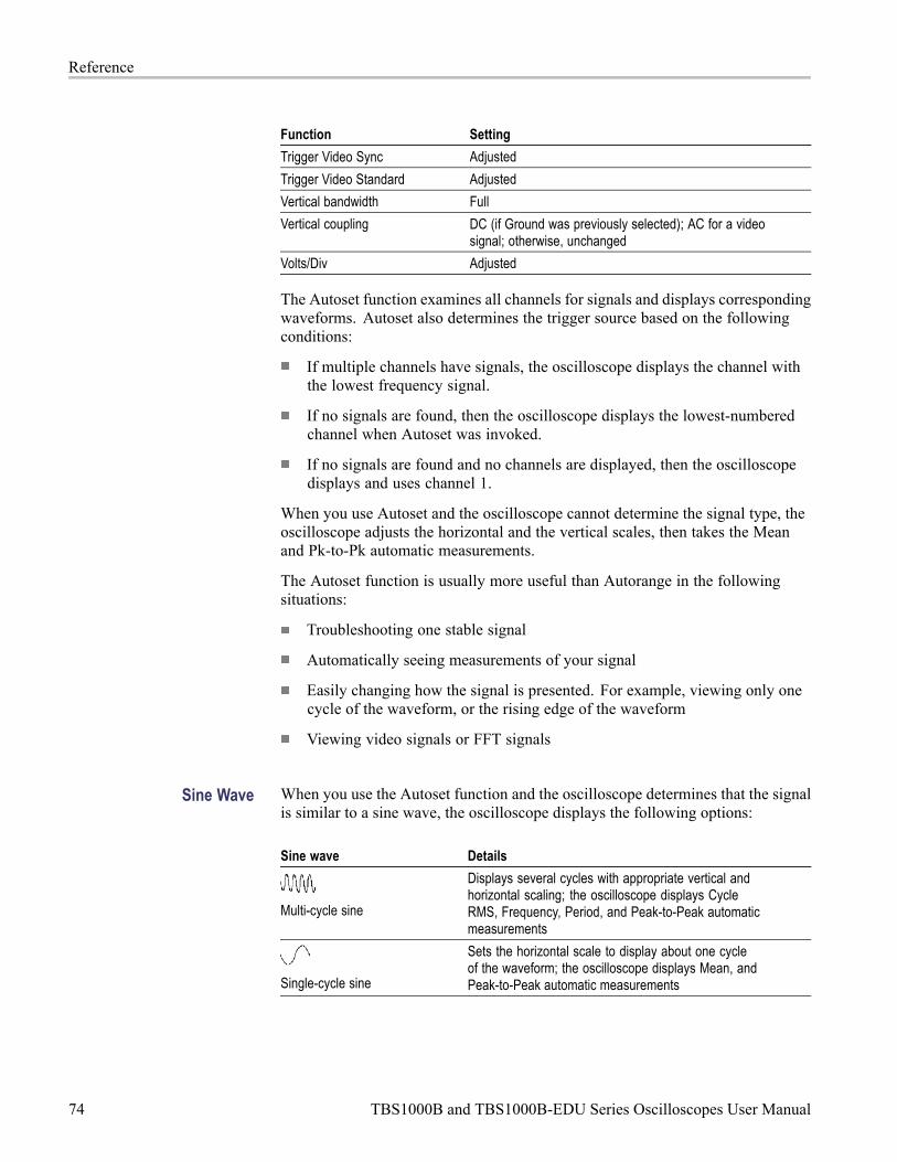
Reference
Function Setting
Trigger Video Sync Adjusted
Trigger Video Standard Adjusted
Vertical bandwidth Full
Vertical coupling DC (if Ground was previously selected); AC for a videosignal; otherwise, unchanged
Volts/Div Adjusted
The Autoset function examines all channels for signals and displays correspondingwaveforms. Autoset also determines the trigger source based on the followingconditions:
If multiple channels have signals, the oscilloscope displays the channel withthe lowest frequency signal.
If no signals are found, then the oscilloscope displays the lowest-numberedchannel when Autoset was invoked.
If no signals are found and no channels are displayed, then the oscilloscopedisplays and uses channel 1.
When you use Autoset and the oscilloscope cannot determine the signal type, theoscilloscope adjusts the horizontal and the vertical scales, then takes the Meanand Pk-to-Pk automatic measurements.
The Autoset function is usually more useful than Autorange in the followingsituations:
Troubleshooting one stable signal
Automatically seeing measurements of your signal
Easily changing how the signal is presented. For example, viewing only onecycle of the waveform, or the rising edge of the waveform
Viewing video signals or FFT signals
Sine Wave When you use the Autoset function and the oscilloscope determines that the signalis similar to a sine wave, the oscilloscope displays the following options:
Sine wave Details
Multi-cycle sine
Displays several cycles with appropriate vertical andhorizontal scaling; the oscilloscope displays CycleRMS, Frequency, Period, and Peak-to-Peak automaticmeasurements
Single-cycle sine
Sets the horizontal scale to display about one cycleof the waveform; the oscilloscope displays Mean, andPeak-to-Peak automatic measurements
74 TBS1000B and TBS1000B-EDU Series Oscilloscopes User Manual
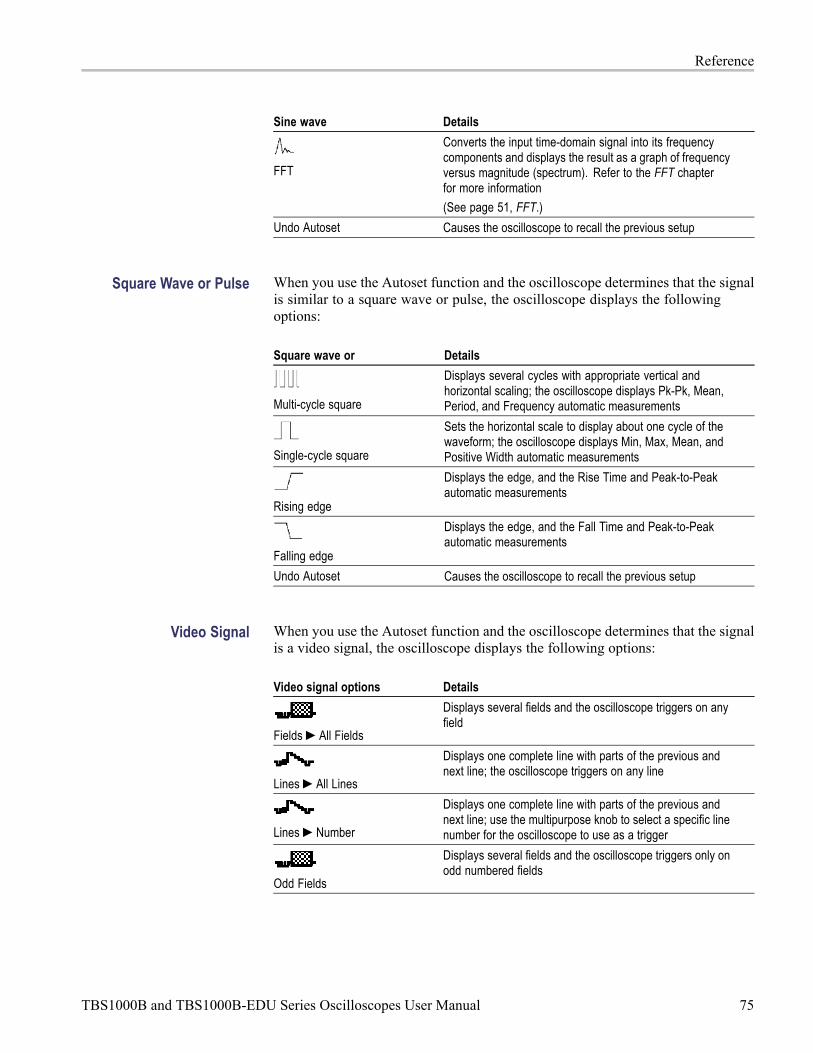
Reference
Sine wave Details
FFT
Converts the input time-domain signal into its frequencycomponents and displays the result as a graph of frequencyversus magnitude (spectrum). Refer to the FFT chapterfor more information
(See page 51, FFT.)
Undo Autoset Causes the oscilloscope to recall the previous setup
Square Wave or Pulse When you use the Autoset function and the oscilloscope determines that the signalis similar to a square wave or pulse, the oscilloscope displays the followingoptions:
Square wave or Details
Multi-cycle square
Displays several cycles with appropriate vertical andhorizontal scaling; the oscilloscope displays Pk-Pk, Mean,Period, and Frequency automatic measurements
Single-cycle square
Sets the horizontal scale to display about one cycle of thewaveform; the oscilloscope displays Min, Max, Mean, andPositive Width automatic measurements
Rising edge
Displays the edge, and the Rise Time and Peak-to-Peakautomatic measurements
Falling edge
Displays the edge, and the Fall Time and Peak-to-Peakautomatic measurements
Undo Autoset Causes the oscilloscope to recall the previous setup
Video Signal When you use the Autoset function and the oscilloscope determines that the signalis a video signal, the oscilloscope displays the following options:
Video signal options Details
Fields All Fields
Displays several fields and the oscilloscope triggers on anyfield
Lines All Lines
Displays one complete line with parts of the previous andnext line; the oscilloscope triggers on any line
Lines Number
Displays one complete line with parts of the previous andnext line; use the multipurpose knob to select a specific linenumber for the oscilloscope to use as a trigger
Odd Fields
Displays several fields and the oscilloscope triggers only onodd numbered fields
TBS1000B and TBS1000B-EDU Series Oscilloscopes User Manual 75

Reference
Video signal options Details
Even Fields
Displays several fields and the oscilloscope triggers only oneven numbered fields
Undo Autoset Causes the oscilloscope to recall the previous setup
NOTE. Video autoset sets the Display Type option to Dot Mode.
CounterUse the counter function from the Function button menu to simultaneouslymonitor two different signal frequencies. This feature provides a more accuratereading than is available with the frequency measurement.
Options Settings Comments
Ch1 On, Off
Ch2 On, Off
Ch1 Trigger Use the multipurpose knob to set thetrigger level.
Ch2 Trigger Use the multipurpose knob to set thetrigger level.
76 TBS1000B and TBS1000B-EDU Series Oscilloscopes User Manual

Reference
Course (EDU models only)Run labs right on your oscilloscope. Also, read theory and procedures, andcapture your lab results right there as well.
Create your course on aPC:
Create new course materials on a PC with separate PC-based software, whichyou can download from www.tektronix.com/software or find on a CD thataccompanied your oscilloscope. After you create the materials, you can distributethem to TBS1000B-EDU oscilloscopes using a USB flash memory device.
You can also check at www.tektronix.com for a separate Courseware Web page,where you can find copies of labs that others have created and uploaded to share.
Load your course on yourTBS1000B-EDU:
To load a new course on a TBS1000B-EDU oscilloscope,
1. Insert the USB memory device that contains your course into the front-panelUSB slot of your TBS1000B-EDU.
2. Push Utility - more - page 1 of 3 Update Course.
3. Use theMultipurpose knob to scroll through the resulting file list and tohighlight the desired course folder. Course folders have an .xpkg suffix.
4. Push Upload Course to load the course into your oscilloscope.
Run labs on yourTBS1000B-EDU:
You can access the lab content via the dedicated Course button located on theon the front panel. Use the oscilloscope’s soft keys and the multipurpose knob toaccess up to 8 courses, which can have up to 30 labs each. Store up to 100 MB ofcourse material on the oscilloscope. Once you choose a lab, you can review theoverview section, perform the lab using the step-by-step procedure, collect data,check and save the data results and generate reports that show the waveformscreated for each step in the procedure.
TBS1000B and TBS1000B-EDU Series Oscilloscopes User Manual 77

Reference
To run your desired lab:
1. Push the Course front-panel button to enable operation of courseware directlyon the oscilloscope.
2. Push a side-bezel menu item to choose the desired course from those listed.
3. Turn theMultipurpose knob to highlight the lab to run. Push the knob toselect the desired lab.
4. On the resulting screen, select the desired content from the side-bezel menu.Read the Overview and the step-by-step Procedure. Push Data Collectionand save results to a USB memory device.
5. When done running the lab, select Report from the side-bezel menu. Use theresulting side-bezel menu to enter your student identification number.
6. Push OK from the side-bezel menu.
7. On the resulting course report, push Save on the side-bezel menu. This willsave the report onto an attached USB memory device.
Course
Overview
Procedure
DataCollection
Reports
Back
78 TBS1000B and TBS1000B-EDU Series Oscilloscopes User Manual

Reference
CursorPush the Cursor button to display the measurement cursors and Cursor Menu,and then use the multipurpose knob to change the position of a cursor.
Options Settings Comments
Type 1 Time, Amplitude, Off Select and display the measurementcursors; Time measures time, frequency,and amplitude; Amplitude measuresamplitude, such as current or voltage
Source Ch1, Ch2, FFT, Math, RefA, Ref B
Choose the waveform on which to takethe cursor measurements
Cursor readouts display the measurement
Δ Displays the absolute value of thedifference (delta) between the cursors
Cursor 1
Cursor 2
Displays selected cursor location (timeis referenced to the trigger position, andamplitude to the reference connection)
1 For an FFT source, measures Frequency and Magnitude.
Delta (Δ) values vary with the following types of cursors:
Time cursors display Δt, 1/ Δt and ΔV (or ΔI, ΔVV, and so on)
Amplitude cursors, and Magnitude cursors (FFT source) display ΔV, ΔI,ΔVV, and so on
Frequency cursors (FFT source) display 1/ΔHz and ΔdB
NOTE. The oscilloscope must display a waveform for the cursors and cursorreadouts to appear.
NOTE. The oscilloscope displays the time and amplitude values for eachwaveform when you use Time cursors.
Key Points Cursor Movement. Use the multipurpose knob to move Cursor 1 or Cursor 2.You can move the cursors only while the Cursor Menu is displayed. The activecursor is represented by a solid line.
Amplitude cursors Time cursors
TBS1000B and TBS1000B-EDU Series Oscilloscopes User Manual 79

Reference
Default SetupPush the Default Setup button to recall most of the factory option and controlsettings, but not all. Appendix D lists the default settings that will be recalled.
DisplayPush the Utility button and Display side-menu selection to choose howwaveforms are presented and to change the appearance of the entire display.
Options Settings Comments
Type Vectors, Dots Vectors fill the space between adjacentsample points in the display
Dots display only the sample points
Persist Off, 1 sec, 2 sec,5 sec, Infinite
Sets the length of time each displayedsample point remains displayed
Format YT, XY YT format displays the vertical voltage inrelation to time (horizontal scale)
XY format displays a dot each time a sampleis acquired on channel 1 and channel 2
Channel 1 voltage or current determines theX coordinate of the dot (horizontal) and thechannel 2 voltage or current determines theY coordinate (vertical)
Backlight 0 to 100% Use the Multipurpose knob to adjust thedisplay backlight.
Depending on the type, waveforms will be displayed in three different styles:solid, dimmed, and broken.
80 TBS1000B and TBS1000B-EDU Series Oscilloscopes User Manual

Reference
1. A solid waveform indicates a channel (live) waveform display. The waveformremains solid when the acquisition is stopped if no controls are changed thatmake the display accuracy uncertain.
Changing the vertical and horizontal controls is allowed on stoppedacquisitions.
2. Reference waveforms appear white and waveforms with persistence appliedappear in the same color as the Main waveform, but with less intensity.
3. A broken line indicates the waveform display no longer matches the controls.This happens when you stop the acquisition, and change a control setting thatthe oscilloscope is not able to apply to the displayed waveform. For example,changing the trigger controls on a stopped acquisition causes a broken-linewaveform.
Key Points Persistence. The oscilloscope displays persistence waveform data with lessintensity than "live" waveform data. With Persistence set to Infinite, record pointsaccumulate until a control is changed.
Option Comments
Off Removes default or old waveforms whenever new waveformsdisplay
Time limit Displays new waveforms at normal intensity and old waveformsat a lower intensity; erases old waveforms when they reachthe time limit
Infinite Older waveforms become less bright but always remain visible;use Infinite persistence to look for infrequent events and tomeasure long term peak-to-peak noise
XY Format. Use the XY format to analyze phase differences, such as thoserepresented by Lissajous patterns. The format plots the voltage on channel 1against the voltage on channel 2, where channel 1 is the horizontal axis andchannel 2 is the vertical axis. The oscilloscope uses the untriggered Sampleacquisition mode and displays data as dots. The sampling rate is fixed at 1 MS/s.
NOTE. The oscilloscope can capture a waveform in normal YT mode at anysampling rate. You can view the same waveform in XY mode. To do so, stop theacquisition and change the display format to XY.
In XY format, the controls operate as follows:
The channel 1 Vertical Scale and Vertical Position controls set the horizontalscale and position.
The channel 2 Vertical Scale and Vertical Position controls continue to setvertical scale and position.
TBS1000B and TBS1000B-EDU Series Oscilloscopes User Manual 81

Reference
The following functions do not work in XY display format:
Autoset (resets display format to YT)
Autorange
Automatic measurements
Cursors
Reference or Math waveforms
Save/Recall Save All
Time base controls
Trigger controls
FFTOptions Settings Comments
Source waveform On or Off
Sources Ch1 or Ch2
Window Hanning, Flattop,or Rectangular
Typically, use Hanning for the best frequencyresolution, Flattop for the best magnitudeaccuracy, and Rectangular for the besttransient analysis.
FFT Zoom X1, X2, X5, or X10
FunctionFor non-EDU models, use the Function button to access: limit test, data logging,the counter, and the trend plot.
For EDU models, use the Function button to access the counter.
82 TBS1000B and TBS1000B-EDU Series Oscilloscopes User Manual

Reference
Non-EDU models Options Settings Comments
Source Defines the source of the waveformsagainst which to run the templatewaveform
Compare To Specifies the limit test template againstwhich to compare the signals defined withthe Source menu item.
Run/Stop Test Toggles between whether to start or stopthe limit test
Template Setup Sets up a limit test waveform template.This is the mask signal you define asthe boundary to compare with the inputsource signal. Do this before running alimit test
Action on Violation Defines the actions the oscilloscope willtake after detecting a violation
Limit Test
Stop After Defines the conditions that will cause theoscilloscope to end limit testing
Data Logging Sets the data logging feature on or off
Source Sets the signal source to log data from
Duration Sets the time duration of data logging inhalf hour increments, from 0.5 hour to 8hours, or in one hour increments, from 8hours to 24 hours, or to indefinite
Data Logging
Select Folder Sets the folder to save the waveform datato
Counter Ch1, Ch2, Ch1 Trigger,Ch2 Trigger
Trend plot Run/Stop, Source 1, Type1, Source 2, Type 2
Plot a graph of one or two measurementsas a function of time.
EDU models Options Settings Comments
Counter Ch1, Ch2, Ch1 Trigger,Ch2 Trigger
TBS1000B and TBS1000B-EDU Series Oscilloscopes User Manual 83
Reference
HelpPush the Help button to display the Help menu. The topics cover all the menuoptions and controls of the oscilloscope.
HorizontalYou can use the horizontal controls to adjust the trigger point location relative tothe acquired waveform and to adjust the horizontal scale (time/division).
A readout near the top right of the screen displays the current horizontal positionin seconds. The oscilloscope also indicates horizontal position with an arrowicon at the top of the graticule.
Knobs and Buttons Horizontal Position Knob. Use to control the position of the trigger relative tothe center of the screen.
The trigger point can be set to the left or the right of the center of the screen. Themaximum number of divisions to the left depends on the Horizontal Scale (timebase) setting. For most scales, the maximum is at least 100 divisions. Placing thetrigger point off the screen to the left is called Delayed Sweep.
Push to center the trigger on the screen.
Horizontal Scale Knob (seconds/division). Use to change the horizontal time scaleto magnify or compress the waveform.
Key Points Horizontal Scale. If waveform acquisition is stopped (using the Run/Stopor Single button), the Horizontal Scale control expands or compresses thewaveform. Use to zoom in on a detail of the waveform.
Scan Mode Display (Roll Mode). When the Horizontal Scale control is set to100 ms/div or slower and the trigger mode is set to Auto, the oscilloscope entersthe Scan acquisition mode. In this mode, the waveform display updates from leftto right. There is no trigger or horizontal position control of waveforms duringscan mode. (See page 71, Scan Mode Display.)
MathPush theMath (M) button to display waveform math operations. Push theMathbutton again to remove math waveforms. (See page 106, Vertical Controls.)
Options Comments
+, -, × Math operations; see the next table
Sources Sources used for the operations; see the next table
84 TBS1000B and TBS1000B-EDU Series Oscilloscopes User Manual

Reference
Options Comments
Position Use the multipurpose knob to set the vertical position of theresultant Math waveform
Vertical Scale Use the multipurpose knob to set the vertical scale of theresultant Math waveform
The Math Menu includes Sources options for each operation.
Operation Sources option Comments
+ (addition) Ch1 + Ch2 Channels 1 and 2 are addedtogether
Ch1 - Ch2 The channel 2 waveform issubtracted from the channel 1waveform
- (subtraction)
Ch2 - Ch1 The channel 1 waveform issubtracted from the channel 2waveform
× (multiplication) Ch1 × Ch2 Channels 1 and 2 are multipliedtogether
Key Points Waveform Units. The combination of source waveform units determine theresulting units for the Math waveform.
Waveform unit Waveform unit Operation Resulting Math unit
V V + or - V
A A + or - A
V A + or - ?
V V × VV
A A × AA
V A × VA
MeasurePush theMeasure button to access automatic measurements. There are 34 typesof measurements available. You can display up to six at a time.
Push the top option button to display the Measure 1 Menu. You can choose thechannel on which to take a measurement in the Source option. You can choose thetype of measurement to take in the Type option. Push the Back option button toreturn to the Measure Menu and display the selected measurements.
Key Points Taking Measurements. You can display up to six automatic measurements at atime. The waveform channel must be on (displayed) to make a measurement.
TBS1000B and TBS1000B-EDU Series Oscilloscopes User Manual 85

Reference
Automated measurements cannot be taken on reference waveforms, or whileusing XY or scan mode. The measurements update about two times per second.
The following tables list each automatic measurement by category: time oramplitude.
Time measurements
Measurement Description
Period The time required to complete the first cycle in a waveformor gated region. Period is the reciprocal of frequency and ismeasured in seconds.
Frequency The first cycle in a waveform or gated region. Frequency is thereciprocal of the period; it is measured in hertz (Hz) where oneHz is one cycle per second.
DelayRR(rising torising)
The time between the mid reference (default 50%) amplitudepoint of two different rising waveforms. See also Phase.
DelayFF(falling tofalling)
The time between the mid reference (default 50%) amplitudepoint of the two different falling waveforms.
DelayRF(rising tofalling)
The time between the mid reference (default 50%) amplitudepoint of the rising and the falling waveforms.
DelayFR(falling torising
The time between the mid reference (default 50%) amplitudepoint of the falling and the rising waveforms.
Rise Time The time required for the leading edge of the first pulse in thewaveform or gated region to rise from the low reference value(default = 10%) to the high reference value (default = 90%) ofthe final value.
Fall Time The time required for the falling edge of the first pulse in thewaveform or gated region to fall from the high reference value(default = 90%) to the low reference value (default = 10%) ofthe final value.
PositiveDuty Cycle
The ratio of the positive pulse width to the signal periodexpressed as a percentage. The duty cycle is measured on thefirst cycle in the waveform or gated region.
NegativeDuty Cycle
The ratio of the negative pulse width to the signal periodexpressed as a percentage. The duty cycle is measured on thefirst cycle in the waveform or gated region.
PositivePulseWidth
The distance (time) between the mid reference (default 50%)amplitude points of a positive pulse. The measurement is madeon the first pulse in the waveform or gated region.
NegativePulseWidth
The distance (time) between the mid reference (default 50%)amplitude points of a negative pulse. The measurement is madeon the first pulse in the waveform or gated region.
86 TBS1000B and TBS1000B-EDU Series Oscilloscopes User Manual

Reference
Time measurements (cont.)
Measurement Description
BurstWidth
The duration of a burst (a series of transient events) and ismeasured over the entire waveform or gated region.
Phase The phase angle difference of signals from two differentchannels, using the rising edge of the first signal compared tothe rising edge of the second signal. .
Amplitude measurements
Measurement Description
PositiveOvershoot
This is measured over the entire waveform or gated region and isexpressed as:Positive Overshoot = (Maximum – High) / Amplitude x 100%.
NegativeOvershoot
This is measured over the entire waveform or gated region and isexpressed as:Negative Overshoot = (Low – Minimum) / Amplitude x 100%.
Pk-Pk The absolute difference between the maximum and minimumamplitude in the entire waveform or gated region.
Amplitude The high value less the low value measured over the entirewaveform or gated region.
High This value is used as 100% whenever high reference, midreference, or low reference values are needed, such as in fall timeor rise time measurements. Calculate using either the min/maxor histogram method. The min/max method uses the maximumvalue found. The histogram method uses the most common valuefound above the midpoint. This value is measured over the entirewaveform or gated region.
TBS1000B and TBS1000B-EDU Series Oscilloscopes User Manual 87

Reference
Amplitude measurements (cont.)
Measurement Description
Low This value is used as 0% whenever high reference, mid reference,or low reference values are needed, such as in fall time orrise time measurements. Calculate using either the min/maxor histogram method. The min/max method uses the minimumvalue found. The histogram method uses the most common valuefound below the midpoint. This value is measured over the entirewaveform or gated region.
Max The most positive peak voltage. Max is measured over the entirewaveform or gated region.
Min The most negative peak voltage. Min is measured over the entirewaveform or gated region.
Mean The arithmetic mean amplitude over the entire waveform or gatedregion.
CycleMean
The arithmetic mean over the first cycle in the waveform or thefirst cycle in the gated region.
RMS The true Root Mean Square voltage over the entire waveform orgated region.
CycleRMS
The true Root Mean Square voltage over the first cycle in thewaveform or the first cycle in the gated region.
Miscellaneous measurements
Measurement Description
RisingEdgeCount
The number of positive transitions from the low reference value tothe high reference value in the waveform or gated region.
FallingEdgeCount
The number of negative transitions from the high reference value tothe low reference value in the waveform or gated region.
88 TBS1000B and TBS1000B-EDU Series Oscilloscopes User Manual

Reference
Miscellaneous measurements (cont.)
Measurement Description
PositivePulseCount
The number of positive pulses that rise above the mid referencecrossing in the waveform or gated region.
NegativePulseCount
The number of negative pulses that fall below the mid referencecrossing in the waveform or gated region.
Area Area measurement is a voltage over time measurement. It returnsthe area over the entire waveform or gated region in volt-seconds.Area measured above ground is positive; area measured belowground is negative.
CycleArea
A voltage over time measurement. The measurement is the areaover the first cycle in the waveform or the first cycle in the gatedregion expressed in volt-seconds. The area above the commonreference point is positive, and the area below the commonreference point is negative.
CursorMean
The arithmetic mean of the waveform data from the selectedstarting to the ending point
CursorRMS
Calculates a true RMS measurement of the waveform data fromthe selected starting to the ending point
Measurement GatingGating confines the measurement to a portion of a waveform defined by thecursors. To use:
1. Push theMeasure front panel button.
2. Push theMeasure Gating On/Off side bezel button.
TBS1000B and TBS1000B-EDU Series Oscilloscopes User Manual 89

Reference
Menu OffPushMenu Off to clear displayed menus from the screen.
Print-Ready ScreenshotsYou can set up the oscilloscope to save print-ready images through the Utility -more - page 1 of 3Options Printer Setup menu.
Option Setting Comments
Ink Saver On, Off Prints the screen image on awhite background when youselect On
Layout 1 Portrait, Landscape Printer output orientation
Abort Printing Stops sending the screen imageto the printer
Paper Size 2 Default, L, 2L, Hagaki Postcard, Card Size, 10 x 15 cm, 4" x 6", 8"x 10", Letter, 11" x 17", A0, A1, A2, A3, A4, A5, A6, A7, A8, A9,B0, B1, B2, B3, B4, B5, B6, B7, B8, B9, 89 mm Roll (L), 127 mmRoll (2L), 100 mm Roll (4"), 210 mm Roll (A4)
Displays settings available onyour PictBridge compatibleprinter
Image Size 2 Default, 2.5 x 3.25 in, L (3.5 x 5 in), 4 x 6 in, 2L (5 x 7 in), 8 x 10 in,4L (7 x 10 in), E, Card, Hagaki card, 6 x 8 cm, 7 x 10 cm, 9 x13 cm, 10 x 15 cm, 13 x 18 cm, 15 x 21 cm, 18 x 24 cm, A4, Letter
Paper Type 2 Default, Plain, Photo, Fast Photo
Print Quality 2 Default, Normal, Draft, Fine
Date Print 2 Default, Off, On
ID Print 2 Default, Off, On
1 The printer may override your selection for best fit.2 If your selection is not supported by the printer, the oscilloscope uses the Default setting.
Reference MenuThe Reference menu can turn on or turn off reference memory waveformsfrom the display. The waveforms are stored in the non-volatile memory of theoscilloscope, and have the following designations: RefA and RefB.
To display (recall) or hide a reference waveform, follow these steps:
1. Push the Ref front panel button.
2. Push the side-menu button corresponding to the reference waveform youwish to display or hide.
90 TBS1000B and TBS1000B-EDU Series Oscilloscopes User Manual
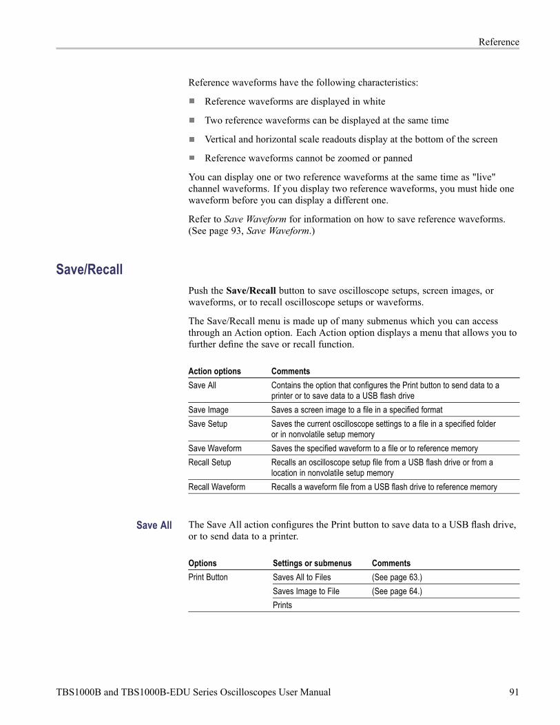
Reference
Reference waveforms have the following characteristics:
Reference waveforms are displayed in white
Two reference waveforms can be displayed at the same time
Vertical and horizontal scale readouts display at the bottom of the screen
Reference waveforms cannot be zoomed or panned
You can display one or two reference waveforms at the same time as "live"channel waveforms. If you display two reference waveforms, you must hide onewaveform before you can display a different one.
Refer to Save Waveform for information on how to save reference waveforms.(See page 93, Save Waveform.)
Save/RecallPush the Save/Recall button to save oscilloscope setups, screen images, orwaveforms, or to recall oscilloscope setups or waveforms.
The Save/Recall menu is made up of many submenus which you can accessthrough an Action option. Each Action option displays a menu that allows you tofurther define the save or recall function.
Action options Comments
Save All Contains the option that configures the Print button to send data to aprinter or to save data to a USB flash drive
Save Image Saves a screen image to a file in a specified format
Save Setup Saves the current oscilloscope settings to a file in a specified folderor in nonvolatile setup memory
Save Waveform Saves the specified waveform to a file or to reference memory
Recall Setup Recalls an oscilloscope setup file from a USB flash drive or from alocation in nonvolatile setup memory
Recall Waveform Recalls a waveform file from a USB flash drive to reference memory
Save All The Save All action configures the Print button to save data to a USB flash drive,or to send data to a printer.
Options Settings or submenus Comments
Saves All to Files (See page 63.)
Saves Image to File (See page 64.)
Print Button
Prints
TBS1000B and TBS1000B-EDU Series Oscilloscopes User Manual 91
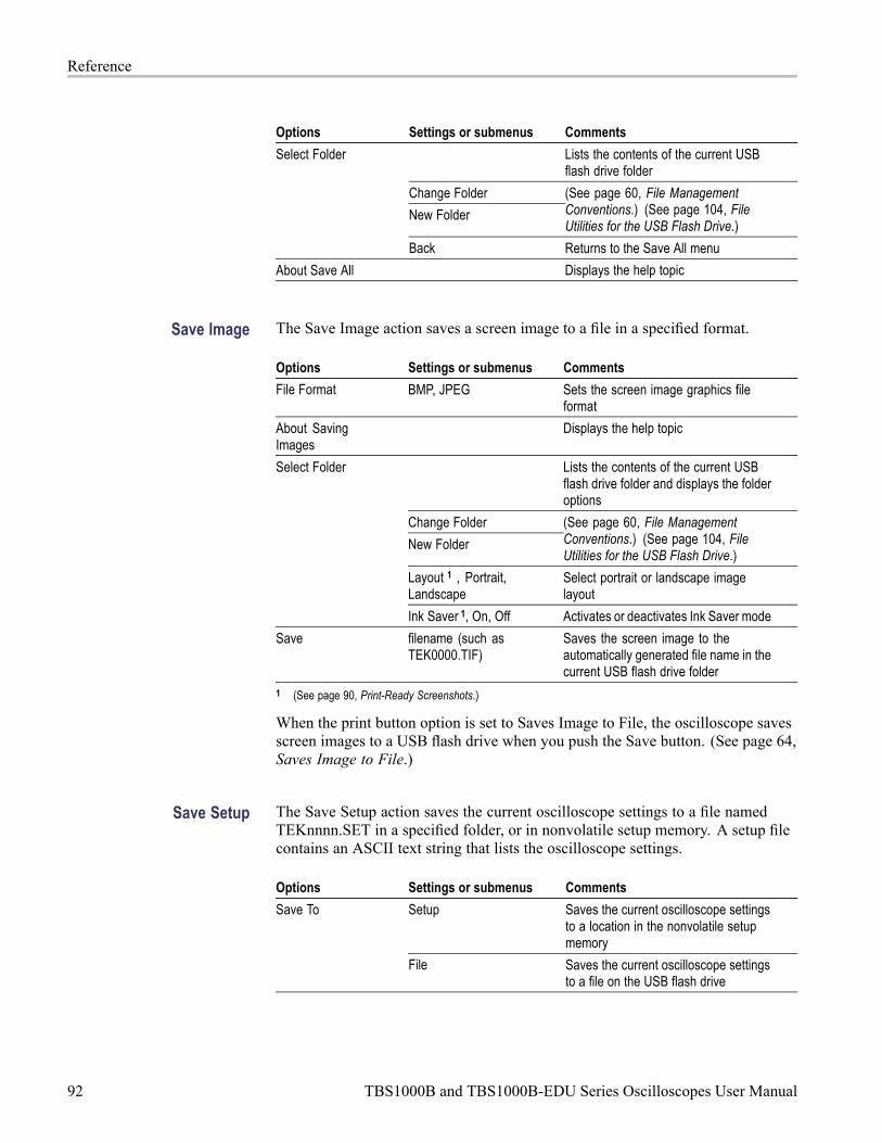
Reference
Options Settings or submenus Comments
Lists the contents of the current USBflash drive folder
Change Folder
New Folder
(See page 60, File ManagementConventions.) (See page 104, FileUtilities for the USB Flash Drive.)
Select Folder
Back Returns to the Save All menu
About Save All Displays the help topic
Save Image The Save Image action saves a screen image to a file in a specified format.
Options Settings or submenus Comments
File Format BMP, JPEG Sets the screen image graphics fileformat
About SavingImages
Displays the help topic
Lists the contents of the current USBflash drive folder and displays the folderoptions
Change Folder
New Folder
(See page 60, File ManagementConventions.) (See page 104, FileUtilities for the USB Flash Drive.)
Layout 1 , Portrait,Landscape
Select portrait or landscape imagelayout
Select Folder
Ink Saver 1, On, Off Activates or deactivates Ink Saver mode
Save filename (such asTEK0000.TIF)
Saves the screen image to theautomatically generated file name in thecurrent USB flash drive folder
1 (See page 90, Print-Ready Screenshots.)
When the print button option is set to Saves Image to File, the oscilloscope savesscreen images to a USB flash drive when you push the Save button. (See page 64,Saves Image to File.)
Save Setup The Save Setup action saves the current oscilloscope settings to a file namedTEKnnnn.SET in a specified folder, or in nonvolatile setup memory. A setup filecontains an ASCII text string that lists the oscilloscope settings.
Options Settings or submenus Comments
Setup Saves the current oscilloscope settingsto a location in the nonvolatile setupmemory
Save To
File Saves the current oscilloscope settingsto a file on the USB flash drive
92 TBS1000B and TBS1000B-EDU Series Oscilloscopes User Manual
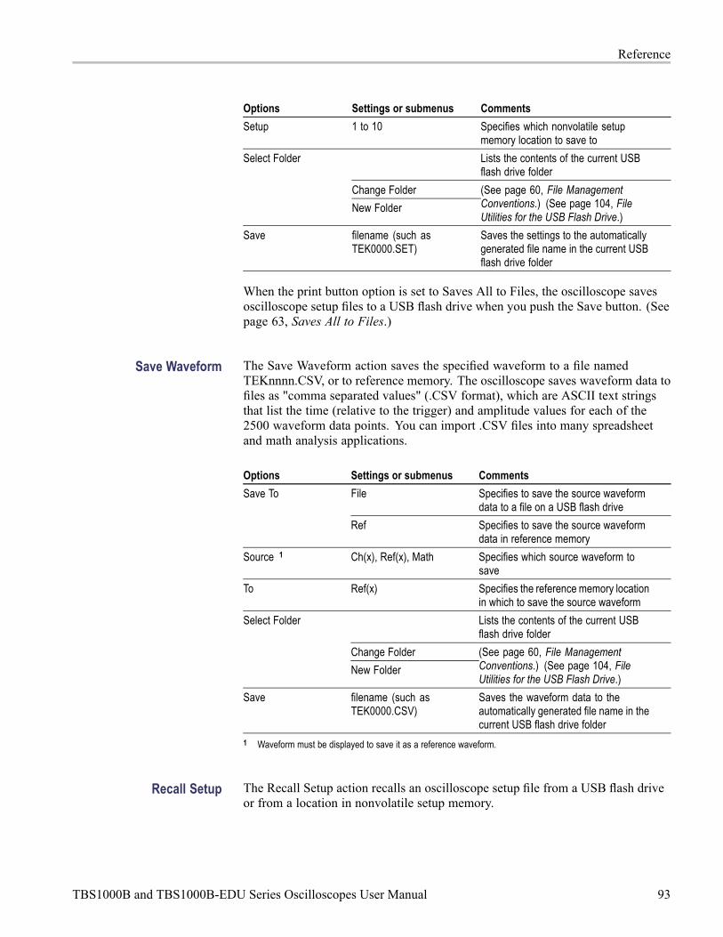
Reference
Options Settings or submenus Comments
Setup 1 to 10 Specifies which nonvolatile setupmemory location to save to
Lists the contents of the current USBflash drive folder
Change Folder
Select Folder
New Folder
(See page 60, File ManagementConventions.) (See page 104, FileUtilities for the USB Flash Drive.)
Save filename (such asTEK0000.SET)
Saves the settings to the automaticallygenerated file name in the current USBflash drive folder
When the print button option is set to Saves All to Files, the oscilloscope savesoscilloscope setup files to a USB flash drive when you push the Save button. (Seepage 63, Saves All to Files.)
Save Waveform The Save Waveform action saves the specified waveform to a file namedTEKnnnn.CSV, or to reference memory. The oscilloscope saves waveform data tofiles as "comma separated values" (.CSV format), which are ASCII text stringsthat list the time (relative to the trigger) and amplitude values for each of the2500 waveform data points. You can import .CSV files into many spreadsheetand math analysis applications.
Options Settings or submenus Comments
File Specifies to save the source waveformdata to a file on a USB flash drive
Save To
Ref Specifies to save the source waveformdata in reference memory
Source 1 Ch(x), Ref(x), Math Specifies which source waveform tosave
To Ref(x) Specifies the reference memory locationin which to save the source waveform
Lists the contents of the current USBflash drive folder
Change Folder
Select Folder
New Folder
(See page 60, File ManagementConventions.) (See page 104, FileUtilities for the USB Flash Drive.)
Save filename (such asTEK0000.CSV)
Saves the waveform data to theautomatically generated file name in thecurrent USB flash drive folder
1 Waveform must be displayed to save it as a reference waveform.
Recall Setup The Recall Setup action recalls an oscilloscope setup file from a USB flash driveor from a location in nonvolatile setup memory.
TBS1000B and TBS1000B-EDU Series Oscilloscopes User Manual 93

Reference
Options Settings or submenus Comments
Setup Specifies to recall a setup from thenonvolatile memory
Recall From
File Specifies to recall a setup file from aUSB flash drive
Setup 1 to 10 Specifies which setup location innonvolatile setup memory to recall
Lists the contents of the current USBflash drive folder to select a file from
Select File
Change Folder (See page 60, File ManagementConventions.) (See page 104, FileUtilities for the USB Flash Drive.)
Recalls the settings from the specifiednonvolatile memory location
Recall
filename (such asTEK0000.SET)
Recalls the oscilloscope settings fromthe specified USB flash drive file
Recall Waveform The Recall Waveform action recalls a waveform file from a USB flash drive to alocation in reference memory.
Options Settings or submenus Comments
To Ref(x) Specifies the reference memory locationto load the waveform to
From File Recalls the file from the USB flash drive
Lists the contents of the current USBflash drive folder and displays the nextfolder option
Change Folder (See page 60, File ManagementConventions.) (See page 104, FileUtilities for the USB Flash Drive.)
Select File
To Specifies the reference memory locationto recall the waveform to
Recall filename (such asTEK0000.CSV)
Loads the waveform from the specifiedfile to the location in reference memoryand displays the waveform
Key Points Saving and Recalling Setups. The complete setup is stored in nonvolatile memory.When you recall the setup, the oscilloscope will be in the mode from which thesetup was saved.
The oscilloscope saves the current setup if you wait three seconds after the lastchange before you power off the oscilloscope. The oscilloscope then recalls thissetup the next time you apply power.
94 TBS1000B and TBS1000B-EDU Series Oscilloscopes User Manual

Reference
Recalling the Default Setup. You can push the Default Setup button to initializethe oscilloscope to a known setup. To view option and control settings that theoscilloscope recalls when you push this button, refer to Appendix D: Default Setup.
Saving and Recalling Waveforms. The oscilloscope must display any waveformthat you want to save. Two-channel oscilloscopes can store two referencewaveforms in internal nonvolatile memory. Four-channel oscilloscopes can storefour, but only display two at a time.
The oscilloscope can display both reference waveforms and channel waveformacquisitions. Reference waveforms are not adjustable, but the oscilloscopedisplays the horizontal and vertical scales at the bottom of the screen.
Trend Plot (non-EDU models only)The trend function plots a graph of measurements as a function of time. You candisplay up to two trend plots simultaneously.
The TrendPlot™ function helps find intermittent faults. To run, select the typeof measurements to capture from either or both channels and then set up theoscilloscope to continuously monitor the signals, plot the data onto the displayand simultaneously save the information to a USB memory device. You’ll be ableto capture data for minutes, hours or days. Just evaluate your requirement and thesize of your USB memory device and then adjust your oscilloscope settings.
To operate:
Options Settings Comments
Run, Stop Run, Stop
Source 1 Ch1, Ch2
Type 1 Minimum, maximum
Source 2 Ch1, Ch2
Type 2 Minimum, maximum
TBS1000B and TBS1000B-EDU Series Oscilloscopes User Manual 95

Reference
Trigger ControlsYou can define the trigger through the Trigger Menu and front-panel controls.
Trigger Types Three types of triggering are available: Edge, Video, and Pulse Width. A differentset of options display for each type of trigger.
Option Details
Edge (default) Triggers the oscilloscope on the rising or falling edge of the inputsignal when it crosses the trigger level (threshold)
Video Displays NTSC or PAL/SECAM standard composite videowaveforms; you trigger on fields or lines of video signals. (Seepage 98, Video Trigger.)
Pulse Triggers on aberrant pulses. (See page 99, Pulse Width Trigger.)
Edge Trigger Use Edge triggering to trigger on the edge of the oscilloscope input signal at thetrigger threshold.
Options Settings Comments
Edge With Edge highlighted, the rising orfalling edge of the input signal is usedfor the trigger
Source Ch1, Ch2, Ext, Ext/5, ACLine
Select the input source as the triggersignal (See page 97.)
Slope Rising, Falling Select to trigger on either the risingor falling edge of the signal
96 TBS1000B and TBS1000B-EDU Series Oscilloscopes User Manual

Reference
Options Settings Comments
Mode Auto, Normal Select the type of triggering (Seepage 97.)
Coupling AC, DC, Noise Reject, HFReject, LF Reject
Selects the components of the triggersignal applied to the trigger circuitry(See page 98.)
Key Points Mode Options. The Auto mode (default) forces the oscilloscope to trigger when itdoes not detect a trigger within a certain amount of time based on the horizontalscale setting. You can use this mode in many situations, such as to monitor thelevel of a power supply output.
Use the Auto mode to let the acquisition free-run in the absence of a valid trigger.This mode allows an untriggered, scanning waveform at 100 ms/div or slowertime base settings.
The Normal mode updates displayed waveforms only when the oscilloscopedetects a valid trigger condition. The oscilloscope displays older waveforms untilthe oscilloscope replaces them with new ones.
Use the Normal mode when you want to see only valid triggered waveforms.When you use this mode, the oscilloscope does not display a waveform untilafter the first trigger.
To perform a Single Sequence acquisition, push the Single button.
Source Options.
Source option Details
Ch1, Ch2 Triggers on a channel whether or not the waveform isdisplayed
Ext Does not display the trigger signal; the Ext option uses thesignal connected to the Ext Trig front-panel BNC and allowsa trigger level range of +1.6 V to -1.6 V
Ext/5 Same as Ext option, but attenuates the signal by a factor offive, and allows a trigger level range of +8 V to -8 V; thisextends the trigger level range
AC Line 1 Uses a signal derived from the power line as the trigger source;trigger coupling is set to DC and the trigger level to 0 volts.
You can use the AC Line when you need to analyze signalsrelated to the frequency of the power line, such as lightingequipment and power supply devices; the oscilloscopeautomatically generates the trigger, sets the Trigger Couplingto DC, and sets the Trigger Level to zero volts.
1 Available only when you select the Edge trigger type.
NOTE. To view an Ext, Ext/5, or AC Line trigger signal, push and hold down theTrigger Menu button for more than 1.5 seconds to enable trigger view.
TBS1000B and TBS1000B-EDU Series Oscilloscopes User Manual 97
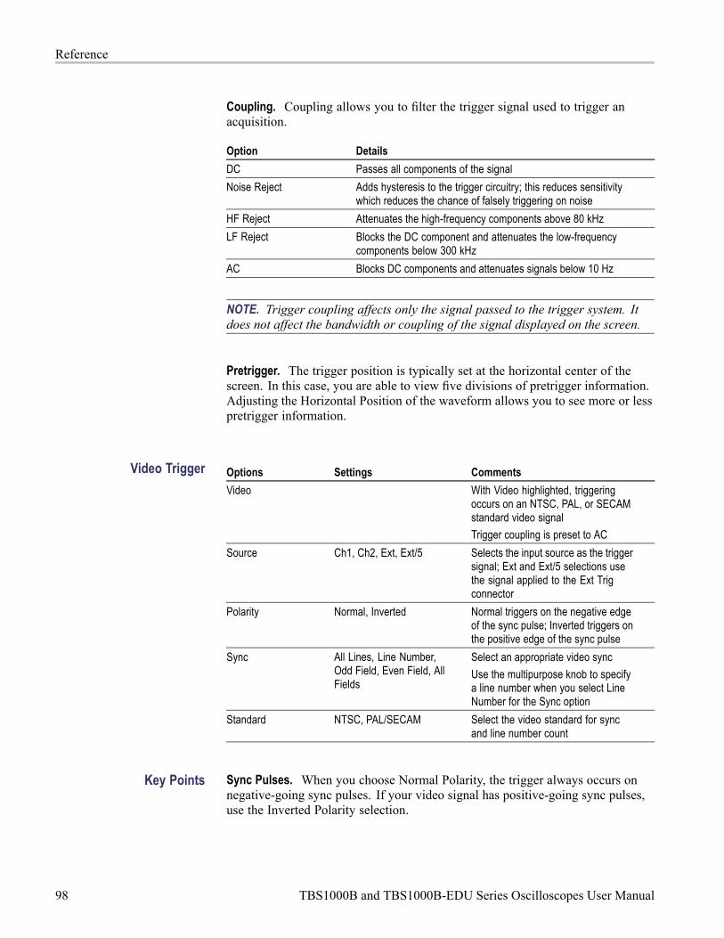
Reference
Coupling. Coupling allows you to filter the trigger signal used to trigger anacquisition.
Option Details
DC Passes all components of the signal
Noise Reject Adds hysteresis to the trigger circuitry; this reduces sensitivitywhich reduces the chance of falsely triggering on noise
HF Reject Attenuates the high-frequency components above 80 kHz
LF Reject Blocks the DC component and attenuates the low-frequencycomponents below 300 kHz
AC Blocks DC components and attenuates signals below 10 Hz
NOTE. Trigger coupling affects only the signal passed to the trigger system. Itdoes not affect the bandwidth or coupling of the signal displayed on the screen.
Pretrigger. The trigger position is typically set at the horizontal center of thescreen. In this case, you are able to view five divisions of pretrigger information.Adjusting the Horizontal Position of the waveform allows you to see more or lesspretrigger information.
Video Trigger Options Settings Comments
Video With Video highlighted, triggeringoccurs on an NTSC, PAL, or SECAMstandard video signal
Trigger coupling is preset to AC
Source Ch1, Ch2, Ext, Ext/5 Selects the input source as the triggersignal; Ext and Ext/5 selections usethe signal applied to the Ext Trigconnector
Polarity Normal, Inverted Normal triggers on the negative edgeof the sync pulse; Inverted triggers onthe positive edge of the sync pulse
Sync All Lines, Line Number,Odd Field, Even Field, AllFields
Select an appropriate video sync
Use the multipurpose knob to specifya line number when you select LineNumber for the Sync option
Standard NTSC, PAL/SECAM Select the video standard for syncand line number count
Key Points Sync Pulses. When you choose Normal Polarity, the trigger always occurs onnegative-going sync pulses. If your video signal has positive-going sync pulses,use the Inverted Polarity selection.
98 TBS1000B and TBS1000B-EDU Series Oscilloscopes User Manual

Reference
Pulse Width Trigger Use Pulse Width triggering to trigger on normal or aberrant pulses.
Options Settings Comments
Pulse With Pulse highlighted, triggeringoccurs on pulses that meet the triggercondition defined by the Source,When, and Set Pulse Width options
Source Ch1, Ch2, Ext, Ext/5 Select the input source as the triggersignal
When =, ≠, <, > Select how to compare the triggerpulse relative to the value selected inthe Pulse Width option
Pulse Width 33 ns to 10.0 sec Use the multipurpose knob to set awidth
Polarity Positive, Negative Select to trigger on positive ornegative pulses
Mode Auto, Normal Select the type of triggering; Normalmode is best for most Pulse Widthtrigger applications
Coupling AC, DC, Noise Reject, HFReject, LF Reject
Selects the components of the triggersignal applied to the trigger circuitry;(See page 96, Edge Trigger.)
More Use to switch between submenupages
Key Points Trigger When. The pulse width of the source must be ≥5 ns for the oscilloscope todetect the pulse.
When options Details
=
≠Triggers the oscilloscope when the signal pulse width is equal to ornot equal to the specified pulse width within a ± 5% tolerance
<
>Triggers the oscilloscope when the source signal pulse width is lessthan or greater than the specified pulse width
TBS1000B and TBS1000B-EDU Series Oscilloscopes User Manual 99

Reference
Refer to the Application Examples chapter for an example of triggering onaberrant pulses. (See page 39, Triggering on a Specific Pulse Width.)
Trigger Frequency Readout The oscilloscope counts the rate at which triggerable events occur to determinetrigger frequency and displays the frequency in the lower right corner of thescreen.
NOTE. The trigger frequency readout shows the frequency of events theoscilloscope might consider to be a trigger, and may be less than the frequency ofthe input signal in Pulse Width trigger mode.
Knobs and Buttons Level Knob. Use to control the Trigger Level.
Push this knob to automatically sets the Trigger Level to be about halfwaybetween the minimum and maximum voltage levels. This can frequently help toquickly stabilize a waveform.
Force Trig Button. Use the Force Trig button to complete the waveformacquisition whether or not the oscilloscope detects a trigger. This is useful forsingle sequence acquisitions and Normal trigger mode. (In Auto trigger mode,the oscilloscope automatically forces triggers periodically if it does not detect atrigger.)
Trigger View. Push the Trigger Menu button for more than 1.5 seconds toenable the Trigger View mode and display the conditioned trigger signal on theoscilloscope. You can use this mode to see the following types of information:
100 TBS1000B and TBS1000B-EDU Series Oscilloscopes User Manual

Reference
Effects of the Trigger Coupling option
AC Line trigger source (Edge Trigger only)
Signal connected to the Ext Trig BNC
Holdoff. You can use the Trigger Holdoff function to produce a stable display ofcomplex waveforms, such as pulse trains. Holdoff is the time between whenthe oscilloscope detects one trigger and when it is ready to detect another. Theoscilloscope will not trigger during the holdoff time. For a pulse train, you canadjust the holdoff time so the oscilloscope triggers only on the first pulse in thetrain.
To use Trigger Holdoff, push the Trigger - more - page 1 of 2 Set TriggerHoldoff option button and use the multipurpose knob to adjust the holdoff. Theresolution of the trigger holdoff varies depending on the horizontal scale setting.
UtilityPush the Utility button to display the Utility Menu.
EDU-models: Options Settings Comments
Display Type (Vectors, Dots),Persist (1 sec, 2 sec. 5sec. Infinite, Off), Format(YT, XY), Backlight (1%to 100%)
Language English, French,German, Italian, Spanish,Japanese, Portuguese,Simplified Chinese,Traditional Chinese,Korean
Selects the display language of theoscilloscope
Do Self Cal Performs a self calibration
Probe check
TBS1000B and TBS1000B-EDU Series Oscilloscopes User Manual 101

Reference
Options Settings Comments
File Utilities Displays folder, file, and USB flash driveoptions (See page 104.)
Options Rear USB Port (autodetect, printer, computer),printer setup, GPIB setup,Set date and time, errorlog
Update course
Enable, DisableAutoset Enable
Change Password
To further enhance the teaching processon EDU oscilloscopes, you (the teacher)can disable the Autoset function. Forthose beginning labs where it is importantfor a student to learn the basic operationof the scope, disabling Autoset willhelp them apply their knowledge ofoscilloscope operation instead of takingshortcuts with the Autoset button
System Status Horizontal, vertical,trigger, miscellaneous
Non-EDU-models: Options Settings Comments
Display Type (Vectors, Dots),Persist (1 sec, 2 sec. 5sec. Infinite, Off), Format(YT, XY), Backlight (1%to 100%)
Language English, French,German, Italian, Spanish,Japanese, Portuguese,Simplified Chinese,Traditional Chinese,Korean
Selects the display language of theoscilloscope
Do Self Cal Performs a self calibration
Probe check
File Utilities Displays folder, file, and USB flash driveoptions (See page 104.)
Options Rear USB Port (autodetect, printer, computer),printer setup, GPIB setup,Set date and time, errorlog
System Status Horizontal, vertical,trigger, miscellaneous
102 TBS1000B and TBS1000B-EDU Series Oscilloscopes User Manual

Reference
Display Settings Comments
Type Vectors or Dots
Persistence 1 second, 2 seconds, 5 seconds,infinite, or off
Format YT or XY YT is the normal oscilloscope mode of operation. It displaysvolltage (vertically) versus time (horizontally).
XY displays channel 1’s voltage versus channel 2’s voltage.
Backlight
File Utiliities Settings Comments
Change Folder
New Folder
Delete
Rename Change the name of a file on the attached USB flash drive.
Format Format the attached USB flash drive. It will erase all fileson the drive.
Update Firmware
Options Settings Comments
Summary of the oscilloscope settingsSystem Status
Misc. Displays model, manufacturer serial number, adaptersconnected, GPIB setup address, firmware version, and otherinformation
Options Rear USB Port: Computer, Auto,Detect, Printer
Printer Setup Changes the output setup
GPIB Setup Address Sets the GPIB address for the TEK-USB-488 adapter (Seepage 67.)
Set Date and Time Sets the date and time (See page 104.)
Error Log Displays a list of any errors logged and the Power Cyclecount
This log is useful if you contact a Tektronix Service Centerfor help.
Key Points System Status. Selecting System Status from the Utility Menu displays the menusavailable for obtaining a list of control settings for each group of oscilloscopecontrols.
Push any front-panel menu button to remove the status screen.
Options Comments
Horizontal Lists horizontal parameters
Vertical Lists vertical parameters of channels
TBS1000B and TBS1000B-EDU Series Oscilloscopes User Manual 103

Reference
Options Comments
Trigger Lists trigger parameters
Misc Lists the model of the oscilloscope, the version number of thesoftware, and the serial number
Lists values of the communications parameters
Setting the Date and Time. You can use the Set Date and Time menu to set theclock date and time. The oscilloscope displays this information, and also uses it totime stamp files written to a USB flash drive. The oscilloscope contains a built-innonreplaceable battery to maintain the clock settings.
The clock does not automatically adjust for seasonal time changes. The calendardoes adjust for Leap years.
Options Comments
Date Push the side-menu button and turn and push the multipurpose knobto set the day, month, and year.
Time Push the side-menu button and turn and push the multipurpose knobto set the hour and minute.
Self Calibration. The self calibration routine optimizes the oscilloscope accuracyfor the ambient temperature. For maximum accuracy, perform a self cal if theambient temperature changes by 5 °C (9 °F ) or more. For accurate calibration,power on the oscilloscope and wait twenty minutes to ensure it is warmed up.Follow the directions on the screen.
Factory calibration uses externally-generated voltages, and requires specializedequipment. The recommended interval is one year. See Contacting Tektronixon the copyright page for information on having Tektronix perform a FactoryCalibration of your oscilloscope.
File Utilities for the USBFlash Drive
One folder is always designated as the current folder. The current folder is thedefault location to save and recall files.
You can use the File Utilities menu to do the following tasks:
List the contents of the current folder
Select a file or folder
Navigate to other folders
Create, rename, and delete files and folders
Format a USB flash drive
104 TBS1000B and TBS1000B-EDU Series Oscilloscopes User Manual

Reference
Options Comments
Navigates to the selected USB flash drive folder. Use themultipurpose knob to select a file or folder, then select theChange Folder menu option.
Change Folder
To return to the previous folder, select the ↑Up folder item andthen select the Change Folder menu option.
New Folder Creates a new folder in the current folder location, namedNEW_FOL, and displays the Rename menu for changing thedefault folder name.
Rename (filename orfolder)
Displays the Rename screen to rename a folder or file, describednext.
Delete (filename orfolder)
Deletes the selected file name or folder; a folder must be emptybefore you can delete it.
Confirm Delete Displays after pressing Delete, to confirm a file delete action.Pressing any button or knob other than Confirm Delete cancelsthe file delete action.
Format Formats the USB flash drive; this deletes all data on the USBflash drive.
Update Firmware Follow the on-screen directions to set up and push the UpdateFirmware option button to start updating firmware.
Rename File or Folder. You can change the names of files and folders on a USBflash drive.
Option Settings Comments
Enters the highlighted alphanumeric character at thecurrent Name field cursor position
A - Z, 0 - 9, _,.
Use the multipurpose knob to select an alphanumericcharacter or the Backspace, Delete Character, or ClearName functions
Backspace Changes the menu button 1 option to the Backspacefunction. Deletes the character to the left of thehighlighted character in the Name field
DeleteCharacter
Changes the menu button 1 option to the DeleteCharacter function. Deletes the highlighted characterfrom the Name field
EnterCharacter
Clear Name Changes the menu button 1 option to Clear Name.Deletes all characters from the Name field
TBS1000B and TBS1000B-EDU Series Oscilloscopes User Manual 105

Reference
Vertical ControlsYou can use the vertical controls to display and remove waveforms, adjust verticalscale and position, set input parameters, and for vertical math operations. (Seepage 84, Math.)
Channel Vertical Menus There is a separate vertical menu for each channel. Each option is set individuallyfor each channel.
Options Settings Comments
Coupling DC, AC, Ground DC passes both AC and DC components of theinput signal
AC blocks the DC component of the input signaland attenuates signals below 10 Hz
Ground disconnects the input signal
Options Settings Comments
BW Limit 20 MHz 1 , Off Limits the bandwidth to reduce display noise;filters the signal to reduce noise and otherunwanted high frequency components
Volts/Div Coarse, Fine Selects the resolution of the Scale (Volts/Div)knob
Coarse defines a 1-2-5 sequence. Finechanges the resolution to small stepsbetween the coarse settings
Probe See the next table Push to adjust Probe options
Invert On, Off Inverts (flips) the waveform with respect tothe reference level
1 Effective bandwidth is 6 MHz with a P2220 probe set to 1X.
The option for voltage and current probes is different: Attenuation or Scale.
Probe options Settings Comments
Probe VoltageAttenuation
1X, 10X, 20X, 50X, 100X,500X, 1000X
Set to match the attenuationfactor of the voltage probeto ensure correct verticalreadouts
Probe Current Scale 5 V/A, 1 V/A, 500 mV/A,200 mV/A, 100 mV/A,20 mV/A, 10 mV/A, 1 mV/A
Set to match the scale ofthe current probe to ensurecorrect vertical readouts
Back Returns to the previousmenu
Knobs Vertical Position Knobs. Use the Vertical Position knobs to move the channelwaveforms up or down on the screen.
106 TBS1000B and TBS1000B-EDU Series Oscilloscopes User Manual

Reference
Vertical Scale (volts/division) Knobs. Use the Vertical Scale knobs to control howthe oscilloscope amplifies or attenuates the source signal of channel waveforms.When you turn a Vertical Scale knob, the oscilloscope increases or decreases thevertical size of the waveform on the screen.
Vertical Measurement Overrange (Clipping). A display of ? in the measurementreadout indicates an invalid value. This may be due to waveforms that extendbeyond the screen (overrange). Adjust the vertical scaling to ensure the readoutis valid.
Key Points Ground Coupling. Use Ground coupling to display a zero-volt waveform.Internally, the channel input is connected to a zero-volt reference level.
Fine Resolution. The vertical scale readout displays the actual volts/divisionsetting while in the fine resolution setting. Changing the setting to coarse does notchange the vertical scale until the Vertical Scale control is adjusted.
Remove Waveform. To remove a waveform from the display, push a channelmenu front panel button. For example, push the 1 (channel 1 menu) button todisplay or remove the channel 1 waveform.
NOTE. You do not have to display a channel waveform to use it as a triggersource or for math operations.
NOTE. You must display a channel waveform to take measurements from it, usecursors on it, or to save it as a Reference waveform or to a file.
Zoom ControlsPush the Zoom button to display a zoomed-in waveform in about three-quartersof the screen. The original waveform will continue to be displayed in aboutone-quarter of the screen. The zoomed in waveform magnifies a waveformhorizontally. Also, use the zoom button to scroll through a zoomed waveform.
Push the Multipurpose knob to enable the knob to either search through thewaveform or zoom in or out on the waveform.
TBS1000B and TBS1000B-EDU Series Oscilloscopes User Manual 107
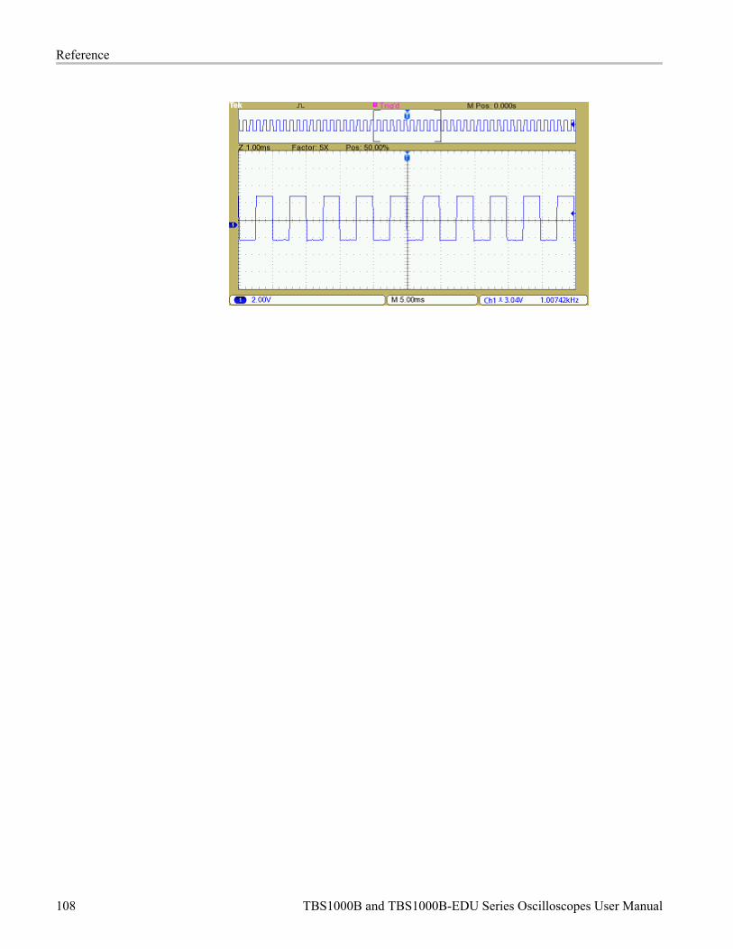
Reference
108 TBS1000B and TBS1000B-EDU Series Oscilloscopes User Manual

Appendix A: SpecificationsYou can find a more complete list of TBS1000B and TBS1000B-EDU productspecifications in the TBS1000B and TBS1000B-EDU Series OscilloscopesService Manual.
Oscilloscope SpecificationsTable 1: Model overview
TBS1052B/EDU TBS1072B/EDU TBS1102B/EDU TBS1152B/EDU TBS1202B/EDU
Bandwidth 50 MHz 70 MHz 100 MHz 150 MHz 200 MHz
Channels 2 2 2 2 2
Sample rate of each channel 1.0 GS/s 1.0 GS/s 2.0 GS/s 2.0 GS/s 2.0 GS/s
Record length 2.5k points at all time bases
Table 2: Vertical system — Analog channels
Characteristic Description
Vertical resolution 8 bits
Input sensitivity range 2 mV to 5 V/div on all models with calibrated fine adjustment
DC gain accuracy ±3% from 10 mV/div to 5 V/div
Maximum input voltage 300 VRMS CAT II; derated at 20 dB/decade above 100 kHz to 13 Vpp AC at 3 MHz
Offset range 2 mV to 200 mV/div; at 1.8 V
>200 mV to 5 V/div; ±45 V
Bandwidth limit 20 MHz
Input coupling AC, DC, Ground
Input impedance 1 MΩ in parallel with 20 pF
Vertical zoom Vertically expand or compress a live or stopped waveform
Table 3: Horizontal system — Analog channels
Characteristic Description
Time base range 5 ns to 50 s/div
Time base accuracy 50 ppm
Horizontal zoom Horizontally expand or compress a live or stopped waveform
Table 4: Input/Output ports
Characteristic Description
USB interface USB host port on the front panel supports USB flash drives.
USB device port on the back of the instrument supports connection to a PC.
GPIB interface Optional
TBS1000B and TBS1000B-EDU Series Oscilloscopes User Manual 109
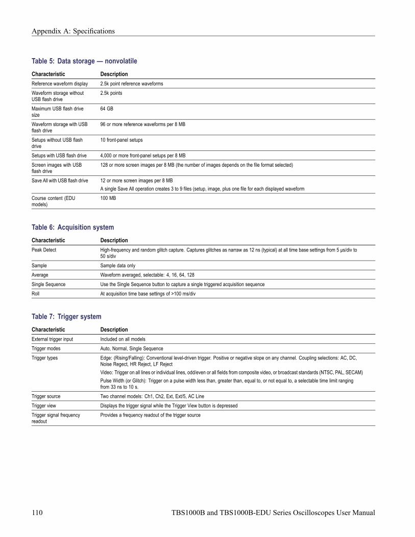
Appendix A: Specifications
Table 5: Data storage — nonvolatile
Characteristic Description
Reference waveform display 2.5k point reference waveforms
Waveform storage withoutUSB flash drive
2.5k points
Maximum USB flash drivesize
64 GB
Waveform storage with USBflash drive
96 or more reference waveforms per 8 MB
Setups without USB flashdrive
10 front-panel setups
Setups with USB flash drive 4,000 or more front-panel setups per 8 MB
Screen images with USBflash drive
128 or more screen images per 8 MB (the number of images depends on the file format selected)
Save All with USB flash drive 12 or more screen images per 8 MB
A single Save All operation creates 3 to 9 files (setup, image, plus one file for each displayed waveform
Course content (EDUmodels)
100 MB
Table 6: Acquisition system
Characteristic Description
Peak Detect High-frequency and random glitch capture. Captures glitches as narraw as 12 ns (typical) at all time base settings from 5 μs/div to50 s/div
Sample Sample data only
Average Waveform averaged, selectable: 4, 16, 64, 128
Single Sequence Use the Single Sequence button to capture a single triggered acquisition sequence
Roll At acquisition time base settings of >100 ms/div
Table 7: Trigger system
Characteristic Description
External trigger input Included on all models
Trigger modes Auto, Normal, Single Sequence
Trigger types Edge: (Rising/Falling): Conventional level-driven trigger. Positive or negative slope on any channel. Coupling selections: AC, DC,Noise Regect, HR Reject, LF Reject
Video: Trigger on all lines or individual lines, odd/even or all fields from composite video, or broadcast standards (NTSC, PAL, SECAM)
Pulse Width (or Glitch): Trigger on a pulse width less than, greater than, equal to, or not equal to, a selectable time limit rangingfrom 33 ns to 10 s.
Trigger source Two channel models: Ch1, Ch2, Ext, Ext/5, AC Line
Trigger view Displays the trigger signal while the Trigger View button is depressed
Trigger signal frequencyreadout
Provides a frequency readout of the trigger source
110 TBS1000B and TBS1000B-EDU Series Oscilloscopes User Manual
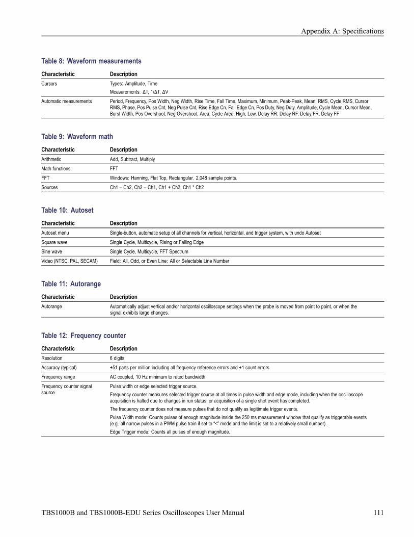
Appendix A: Specifications
Table 8: Waveform measurements
Characteristic Description
Cursors Types: Amplitude, Time
Measurements: ΔT, 1/ΔT, ΔV
Automatic measurements Period, Frequency, Pos Width, Neg Width, Rise Time, Fall Time, Maximum, Minimum, Peak-Peak, Mean, RMS, Cycle RMS, CursorRMS, Phase, Pos Pulse Cnt, Neg Pulse Cnt, Rise Edge Cn, Fall Edge Cn, Pos Duty, Neg Duty, Amplitude, Cycle Mean, Cursor Mean,Burst Width, Pos Overshoot, Neg Overshoot, Area, Cycle Area, High, Low, Delay RR, Delay RF, Delay FR, Delay FF
Table 9: Waveform math
Characteristic Description
Arithmetic Add, Subtract, Multiply
Math functions FFT
FFT Windows: Hanning, Flat Top, Rectangular. 2,048 sample points.
Sources Ch1 – Ch2, Ch2 – Ch1, Ch1 + Ch2, Ch1 * Ch2
Table 10: Autoset
Characteristic Description
Autoset menu Single-button, automatic setup of all channels for vertical, horizontal, and trigger system, with undo Autoset
Square wave Single Cycle, Multicycle, Rising or Falling Edge
Sine wave Single Cycle, Multicycle, FFT Spectrum
Video (NTSC, PAL, SECAM) Field: All, Odd, or Even Line: All or Selectable Line Number
Table 11: Autorange
Characteristic Description
Autorange Automatically adjust vertical and/or horizontal oscilloscope settings when the probe is moved from point to point, or when thesignal exhibits large changes.
Table 12: Frequency counter
Characteristic Description
Resolution 6 digits
Accuracy (typical) +51 parts per million including all frequency reference errors and +1 count errors
Frequency range AC coupled, 10 Hz minimum to rated bandwidth
Frequency counter signalsource
Pulse width or edge selected trigger source.
Frequency counter measures selected trigger source at all times in pulse width and edge mode, including when the oscilloscopeacquisition is halted due to changes in run status, or acquisition of a single shot event has completed.
The frequency counter does not measure pulses that do not qualify as legitimate trigger events.
Pulse Width mode: Counts pulses of enough magnitude inside the 250 ms measurement window that qualify as triggerable events(e.g. all narrow pulses in a PWM pulse train if set to “<” mode and the limit is set to a relatively small number).
Edge Trigger mode: Counts all pulses of enough magnitude.
TBS1000B and TBS1000B-EDU Series Oscilloscopes User Manual 111

Appendix A: Specifications
Table 13: Display system
Characteristic Description
Interpolation Sin (x)/x
Waveform styles Dots, vectors
Persistence Off, 1 s, 2 s, 5 s, infinite
Format YT or XY
Table 14: Courseware software: minimum requirements needed to install the Courseware software
Characteristic Description
Operating System Windows XP, Windows 7, Windows 8, Linux (Ubantu 12.04, 12.10, 13.04 or Fedora 18, 19)
RAM 512 Megabytes (MB)
Disk space 1 Gigabyte of available hard disk space
Display XVGA 1024 * 768 with 120 dpi font size recommended
Removable media CD-ROM or EVE drive
Peripherals Keyboard and Microsoft mouse or other compatible pointing device
Table 15: Physical characteristics
mm inches
Height 158.0 6.22
Width 326.3 12.85
Dimensions
Depth 124.2 4.89
mm inches
Height 266.7 10.5
Width 476.2 18.75
Shipping dimensions
Depth 228.6 9.0
kg lb.
Instrument only 2.0 4.4Weight
Instrument with accessories 2.2 4.9
mm inches
Width 482.6 19.0
Height 177.8 7.0
RM2000B rackmount
Depth 108.0 4.25
Table 16: Environmental
Characteristic Description
Temperature Operating: 0 to +50 °C
Non-operating: –40 to +71 °C
Humidity Operating and non-operating:
Up to 85% relative humidity (RH) at or below +40 °C
Up to 45% RH at or below +50 °C
Altitude Operating and non-operating:
Up to 3,000 m (9,843 feet)
112 TBS1000B and TBS1000B-EDU Series Oscilloscopes User Manual
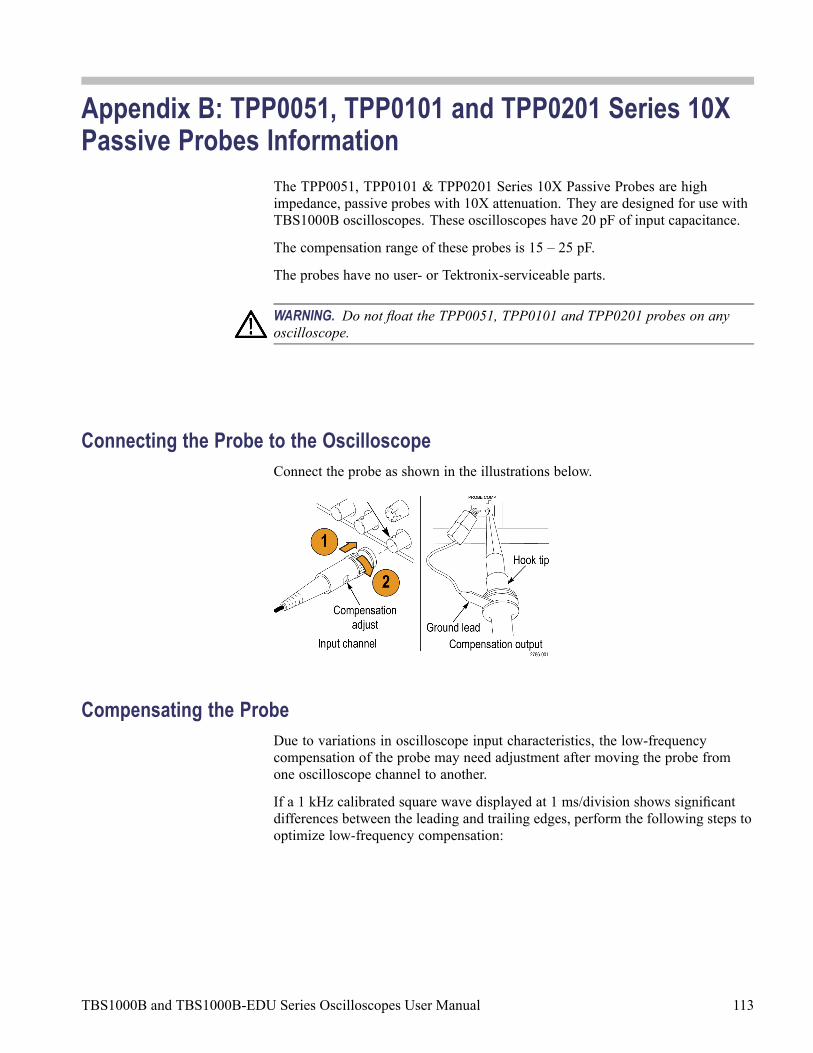
Appendix B: TPP0051, TPP0101 and TPP0201 Series 10XPassive Probes Information
The TPP0051, TPP0101 & TPP0201 Series 10X Passive Probes are highimpedance, passive probes with 10X attenuation. They are designed for use withTBS1000B oscilloscopes. These oscilloscopes have 20 pF of input capacitance.
The compensation range of these probes is 15 – 25 pF.
The probes have no user- or Tektronix-serviceable parts.
WARNING. Do not float the TPP0051, TPP0101 and TPP0201 probes on anyoscilloscope.
Connecting the Probe to the OscilloscopeConnect the probe as shown in the illustrations below.
Compensating the ProbeDue to variations in oscilloscope input characteristics, the low-frequencycompensation of the probe may need adjustment after moving the probe fromone oscilloscope channel to another.
If a 1 kHz calibrated square wave displayed at 1 ms/division shows significantdifferences between the leading and trailing edges, perform the following steps tooptimize low-frequency compensation:
TBS1000B and TBS1000B-EDU Series Oscilloscopes User Manual 113

Appendix B: TPP0051, TPP0101 and TPP0201 Series 10X Passive Probes Information
1. Connect the probe to the oscilloscope channel that you plan to use for yourmeasurements.
2. Connect the probe to the probe compensation output terminals on theoscilloscope front panel.
WARNING. To avoid electric shock, only connect to the Probe Comp signal on theoscilloscope when making this adjustment.
3. Push Autoset or otherwise adjust your oscilloscope to display a stablewaveform.
4. Adjust the trimmer in the probe until you see a perfectly flat-top square waveon the display. (See illustration.)
WARNING. To avoid electric shock, only use the insulated adjustment tool whenmaking compensation adjustments.
Connecting the Probe to the CircuitUse the standard accessories included with the probe to connect to your circuit.
WARNING. To avoid electric shock when using the probe or accessories, keepfingers behind the finger guard of the probe body and accessories.
To reduce risk of shock, ensure the ground lead and ground spring are fully matedbefore connecting the probe to the circuit under test.
114 TBS1000B and TBS1000B-EDU Series Oscilloscopes User Manual

Appendix B: TPP0051, TPP0101 and TPP0201 Series 10X Passive Probes Information
Standard AccessoriesThe accessories included with the probe are shown below.
Item Description
Color bands
Use these bands to identify theoscilloscope channel at the probe head.
Reorder Tektronix part number016-0633-xx (5 pairs)
Hook tip
Press the hook tip onto probe tip andthen clamp the hook onto the circuit.
Reorder Tektronix part number013-0362-xx
Ground lead, with alligator clip
Secure the lead to the probe headground and then to your circuit ground.
Reorder Tektronix part number196-3521-xx
Ground spring
The ground spring minimizesaberrations on high-frequency signalscaused by the inductance of the groundpath, giving you measurements withgood signal fidelity.
Attach the spring to the ground band onthe probe tip. You can bend the springout to ~0.75 in. away from the signaltest point.
Reorder Tektronix part number016-2028-xx (2 ea.)
Adjustment tool
Reorder Tektronix part number003-1433-xx
TBS1000B and TBS1000B-EDU Series Oscilloscopes User Manual 115

Appendix B: TPP0051, TPP0101 and TPP0201 Series 10X Passive Probes Information
Optional AccessoriesYou can order the following accessories for your probe.
Accessory Part number
Alligator Ground Lead, 12 in 196-3512-xx
6” Clip-on Ground Lead 196-3198-xx
Ground Spring, Short, 2 ea. 016-2034-xx
MicroCKT Test Tip 206-0569-xx
Micro Hook Tip 013-0363-xx
Universal IC Cap 013-0366-xx
Circuit Board Test Point/PCB Adapter 016-2016-xx
Wire, spool, 32 AWG 020-3045-xx
SpecificationsTable 17: Electrical and mechanical specifications
Characteristic TPP0051 TPP0101 TPP0201
Bandwidth (–3 dB) DC to 50 MHz DC to 100 MHz DC to 200 MHz
System attenuationaccuracy
10:1 ±3.2% 10:1 ±3.2% 10:1 ±3.2%
Compensation range 15 pF – 25 pF 15 pF – 25 pF 15 pF – 25 pF
System inputresistance @ DC
10 MΩ ±1.5% 10 MΩ ±1.5% 10 MΩ ±1.5%
System inputcapacitance
<12 pF <12 pF <12 pF
System rise time(typical)
<3.5 ns <3.5 ns <2.3 ns
Propagation delay ~6.1 ns ~6.1 ns ~6.1 ns
Maximum inputvoltage
300 VRMS CAT II 300 VRMS CAT II 300 VRMS CAT II
Cable length 1.3 m 1.3 m 1.3 m
116 TBS1000B and TBS1000B-EDU Series Oscilloscopes User Manual

Appendix B: TPP0051, TPP0101 and TPP0201 Series 10X Passive Probes Information
Table 18: Environmental specifications
Characteristics Description
TemperatureOperatingNonoperating
–10 °C to +55 °C (14 °F to +131 °F)–51 °C to +71 °C (–60 °F to +160 °F)
HumidityOperating andNon-Operating
5% to 95% relative humidity (%RH) up to +30 °C (86 °F), 5% to65% RH above +30° C up to +55 °C (131 °F)
AltitudeOperatingNonoperating
3.0 km (10,000 ft) maximum12.2 km (40,000 ft) maximum
Performance Graphs
TBS1000B and TBS1000B-EDU Series Oscilloscopes User Manual 117

Appendix B: TPP0051, TPP0101 and TPP0201 Series 10X Passive Probes Information
Table 19: Certifications and compliances
Characteristics Description
EC Declaration ofConformity
Compliance was demonstrated to the following specification as listedin the Official Journal of the European Communities:
Low Voltage Directive 2006/95/EC:
EN61010-031: 2002
Safety Standards UL61010-031;2007CAN/CSA C22.2 No. 61010-031-07IEC61010-031; IEC 61010-031/A1:2008
Category Examples of Products in this Category
CAT III Distribution-level mains, fixed installation
CAT II Local-level mains, appliances, portable equipment
MeasurementCategoryDescriptions
CAT I Circuits not directly connected to mains.
Pollution Degree 2 Do not operate in environments where cond–uctive pollutants may be present (as defined in IEC 61010-1). Ratedfor indoor use only.
Equipment Recycling. This product complies with the European Union’srequirements according to Directive 2002/96/EC on waste electrical andelectronic equipment (WEEE). For more information about recycling options,check the Support/Service section of the Tektronix Web site (www.tektronix.com).
Safety SummaryReview the following safety precautions to avoid injury and prevent damage tothis product or any products connected to it. To avoid potential hazards, use thisproduct only as specified. Using the probe or accessories in a manner not specifiedcould result in a shock or fire hazard.
To Avoid Fire or PersonalInjury
Ground-Referenced Oscilloscope Use. Do not float the reference lead of thisprobe when using with ground referenced oscilloscopes (for example, TBS seriesoscilloscopes). The reference lead must be connected to earth potential (0 V).
Connect and Disconnect Properly. Connect the probe output to the measurementinstrument before connecting the probe to the circuit under test. Disconnectthe probe input and the probe reference lead from the circuit under test beforedisconnecting the probe from the measurement instrument.
Avoid Electric Shock. Do not connect or disconnect probes or test leads whilethey are connected to a voltage source.
Observe All Terminal Ratings. To avoid fire or shock hazard, observe all ratingsand markings on the product. Consult the product manual for further ratingsinformation before making connections to the product.
118 TBS1000B and TBS1000B-EDU Series Oscilloscopes User Manual

Appendix B: TPP0051, TPP0101 and TPP0201 Series 10X Passive Probes Information
Avoid Electric Shock. When using probe accessories, never exceed the lowestrating of the probe or its accessory, whichever is less, including the measurementcategory and voltage rating.
Inspect the Probe and Accessories. Before each use, inspect the probe andaccessories for damage (cuts, tears, defects in the probe body, accessories, cablejacket, etc.). Do not use if damaged.
Do Not Operate in Wet/Damp Conditions.
Do Not Operate in an Explosive Atmosphere.
Keep Product Surfaces Clean and Dry.
Safety Terms and SymbolsTerms in This Manual.
These terms may appear in this manual:
WARNING. Warning statements identify conditions or practices that could resultin injury or loss of life.
CAUTION. Caution statements identify conditions or practices that could result indamage to this product or other property.
Symbols on the Product. These symbols may appear on the product:
TBS1000B and TBS1000B-EDU Series Oscilloscopes User Manual 119

Appendix B: TPP0051, TPP0101 and TPP0201 Series 10X Passive Probes Information
120 TBS1000B and TBS1000B-EDU Series Oscilloscopes User Manual

Appendix C: AccessoriesAll accessories (standard and optional) are available by contacting your localTektronix field office.
Standard Accessories
TPP0051 (TBS1052B and TBS1052B–EDU) 10X Passive Voltage Probe,
The TPP0051 probes have a system bandwidth of DC to 50 MHz at –3 dB and shipstandard with TBS1000B oscilloscope models that have bandwidths up to 50 MHz.
TPP0101 (TBS1072B, TPS1072B-EDU, TBS1102B, TBS1102B-EDU) 10X PassiveVoltage Probe,
The TPP0101 probes have a system bandwidth of DC to 100 MHz at –3 dB and shipstandard with TBS1000B oscilloscope models that have bandwidths up to 100 MHz.
TPP0201 (TBS1152B, TBS1152B–EDU, TBS1202B, TBS1202B–EDU) 10X PassiveVoltage Probe.
The TPP0201 probes have a system bandwidth of DC to 200 MHz at –3 dB and shipstandard with TBS1000B models with bandwidths greater than 100 MHz.
TBS1000B Oscilloscope Compliance and Safety Instructions. (English, Japanese,Simplified Chinese) (071-3223-XX) A single printed document is included. Refer to theOptional Accessories for a complete list of available language manuals.
Customer Documentation Browser CD-ROM. This CD offers additional productinformation (063-4512-XX).
Power cord Specify plug option
NIM/NIST Traceable certificate of calibration
5-year warranty Covers labor and parts for defects in materials and workmanship for 5 years, excludingprobes and accessories Probes and accessories are not covered by the oscilloscopewarranty and service offerings. Refer to the data sheet of each probe and accessorymodel for its unique warranty and calibration terms.
Optional Accessories
P6101B 1X Passive Voltage Probe. The P6101B probe has a 15 MHz bandwidthwith a rating of 300 VRMS CAT II.
RM2000B Rackmount Kit. The RM2000B Rackmount Kit lets you install aTBS1000B series oscilloscope into an industry-standard 19 inch rack. The rackmountkit requires seven inches (18 cm) of vertical rack space. You can turn the oscilloscopepower on or off from the front of the rackmount kit. The rackmount kit does not haveslide-out capability.
TBS1000B and TBS1000B-EDU Series Oscilloscopes User Manual 121

Appendix C: Accessories
TBS1000B, TBS1000B-EDU, TDS2000C and TPS2000 Series Digital OscilloscopesProgrammer Manual . The PDF programmer manual (077-0444-XX, English)provides command and syntax information.
TBS1000B and TBS1000B-EDU Series Digital Storage Oscilloscope ServiceManual. The PDF service manual (077-0897-XX, English) provides module-levelrepair information.
TBS1000B and TBS1000B-EDU Series Digital Storage Oscilloscope UserManuals. The PDF user manual is available in these languages:
English, 077-0886-XX
French, 077-0887-XX
Italian, 077-0888-XX
German, 077-0889-XX
Spanish, 077-0890-XX
Japanese, 077-0891-XX
Portuguese, 077-0892-XX
Simplified Chinese, 077-0893-XX
Traditional Chinese, 077-0894-XX
Korean, 077-0895-XX
Russian, 077-0896-XX
International Power Cords. In addition to the power cord shipped with youroscilloscope, you can obtain the following cords:
Option A0, North American 120 V, 60 Hz, 161-0066-00
Option A1, European 230 V, 50 Hz, 161-0066-09
Option A2, United Kingdom 230 V, 50 Hz, 161-0066-10
Option A3, Australian 240 V, 50 Hz, 161-0066-13
Option A5, Switzerland 230 V, 50 Hz, 161-0154-00
Option A6, Japan 100 V, 50/60 Hz, 161–0342–00
Option A10, China 220 V, 50 Hz, 161-0304-00
Option A11, India 230 V, 50 Hz, 161-0400-00
Option A12, Brazil 127/220 V, 60 Hz, 161-0357-00
TEK-USB-488 Adapter. The GPIB adapter allows you to connect your oscilloscope toa GPIB controller.
Soft Case. The soft case (AC2100) protects the oscilloscope from damage andprovides space for probes, a power cord, and manuals.
Transit Case. The transit case (HCTEK4321) provides shock, vibration, impact andmoisture protection for the oscilloscope when you transport it from one place toanother. The required soft case fits inside the transit case.
122 TBS1000B and TBS1000B-EDU Series Oscilloscopes User Manual

Appendix D: Cleaning
General CareDo not store or leave the oscilloscope where the LCD display will be exposed todirect sunlight for long periods of time.
CAUTION. To avoid damage to the oscilloscope or probes, do not expose themto sprays, liquids, or solvents.
CleaningInspect the oscilloscope and probes as often as operating conditions require. Toclean the exterior surface, perform the following steps:
1. Remove loose dust on the outside of the oscilloscope and probes with alint-free cloth. Use care to avoid scratching the clear glass display filter.
2. Use a soft cloth dampened with water to clean the oscilloscope. Use anaqueous solution of 75% isopropyl alcohol for more efficient cleaning.
CAUTION. To avoid damage to the surface of the oscilloscope or probes, do notuse any abrasive or chemical cleaning agents.
TBS1000B and TBS1000B-EDU Series Oscilloscopes User Manual 123

Appendix D: Cleaning
124 TBS1000B and TBS1000B-EDU Series Oscilloscopes User Manual

Appendix E: Default SetupThis appendix describes the options, buttons and controls that change settingswhen you push the Default Setup button. The last page of this appendix listssettings that do not change.
NOTE. When you push the Default Setup button, the oscilloscope displays thechannel 1 waveform and removes all other waveforms.
Menu or system Option, button, or knob Default setting
(three mode options) Sample
Averages 16
Acquire
Run/Stop Run
Autorange OffAutorange
Mode Vertical and Horizontal
Type OffCursor
Source Ch1
Type Vectors
Persist Off
Format YT
Display
Backlight 60%
Source Ch1
Window Hanning
FFT
FFT Zoom X1
Position 0.00 sHorizontal
Scale (seconds/division) 500 μs
Operation -
Sources Ch1 - Ch2
Position 0 divs
Math
Vertical Scale 2 V
Source Ch1Measure (all)
Type None
Type Edge
Source Ch1
Slope Rising
Mode Auto
Coupling DC
Trigger
Holdoff 500.0 ns
TBS1000B and TBS1000B-EDU Series Oscilloscopes User Manual 125

Appendix E: Default Setup
Menu or system Option, button, or knob Default setting
Coupling DC
BW Limit Off
Vertical scale(volts/division)
Coarse
Probe Voltage
Voltage ProbeAttenuation
10X
Current Probe Scale 10 A/V
Invert Off
Position 0.00 divs (0.00 V)
Vertical system, allchannels
Scale (volts/division) 1.00 V
The Default Setup button does not reset the following settings:
Language option
Saved setups
Saved reference waveforms
Calibration data
GPIB setup
Probe setup (type and attenuation factor)
Date and time
Current folder on the USB flash drive
126 TBS1000B and TBS1000B-EDU Series Oscilloscopes User Manual

Appendix F: Font LicensesThe following license agreements cover Asian fonts used in the TBS1000B seriesoscilloscopes.
Copyright © 1988 The Institute of Software, Academia Sinica.
Correspondence Address: P.O.Box 8718, Beijing, China 100080.
Permission to use, copy, modify, and distribute this software and its documentationfor any purpose and without fee is hereby granted, provided that the abovecopyright notices appear in all copies and that both those copyright notices andthis permission notice appear in supporting documentation, and that the nameof "the Institute of Software, Academia Sinica" not be used in advertising orpublicity pertaining to distribution of the software without specific, written priorpermission. The Institute of Software, Academia Sinica, makes no representationsabout the suitability of this software for any purpose. It is provided "as is" withoutexpress or implied warranty.
THE INSTITUTE OF SOFTWARE, ACADEMIA SINICA, DISCLAIMS ALLWARRANTIES WITH REGARD TO THIS SOFTWARE, INCLUDING ALLIMPLIED WARRANTIES OF MERCHANTABILITY AND FITNESS, IN NOEVENT SHALL THE INSTITUTE OF SOFTWARE, ACADEMIA SINICA,BE LIABLE FOR ANY SPECIAL, INDIRECT OR CONSEQUENTIALDAMAGES OR ANY DAMAGES WHATSOEVER RESULTING FROM LOSSOF USE, DATA OR PROFITS, WHETHER IN AN ACTION OF CONTRACT,NEGLIGENCE OR OTHER TORTIOUS ACTION, ARISING OUT OF OR INCONNECTION WITH THE USE OR PERFORMANCE OF THIS SOFTWARE.
© Copyright 1986-2000, Hwan Design Inc.
You are hereby granted permission under all Hwan Design propriety rights touse, copy, modify, sublicense, sell, and redistribute the 4 Baekmuk truetypeoutline fonts for any purpose and without restriction; provided, that this noticeis left intact on all copies of such fonts and that Hwan Design Int.'s trademark isacknowledged as shown below on all copies of the 4 Baekmuk truetype fonts.
BAEKMUK BATANG is a registered trademark of Hwan Design Inc.BAEKMUK GULIM is a registered trademark of Hwan Design Inc. BAEKMUKDOTUM is a registered trademark of Hwan Design Inc. BAEKMUK HEADLINEis a registered trademark of Hwan Design Inc.
© Copyright 2000-2001 /efont/ The Electronic Font Open Laboratory. All rightsreserved.
TBS1000B and TBS1000B-EDU Series Oscilloscopes User Manual 127

Appendix F: Font Licenses
Redistribution and use in source and binary forms, with or without modification,are permitted provided that the following conditions are met:
Redistribution of source code must retain the above copyright notice, this listof conditions and the following disclaimer.
Redistributions in binary form must reproduce the above copyright notice, thislist of conditions and the following disclaimer in the documentation and/orother materials provided with the distribution.
Neither the name of the team nor the names of its contributors may be usedto endorse or promote products derived from this font without specific priorwritten permission.
THIS FONT IS PROVIDED BY THE TEAM AND CONTRIBUTORS “ASIS'' AND ANY EXPRESS OR IMPLIED WARRANTIES, INCLUDING, BUTNOT LIMITED TO, THE IMPLIED WARRANTIES OF MERCHANTABILITYAND FITNESS FOR A PARTICULAR PURPOSE ARE DISCLAIMED. INNO EVENT SHALL THE TEAM OR CONTRIBUTORS BE LIABLE FORANY DIRECT, INDIRECT, INCIDENTAL, SPECIAL, EXEMPLARY, ORCONSEQUENTIAL DAMAGES (INCLUDING, BUT NOT LIMITED TO,PROCUREMENT OF SUBSTITUTE GOODS OR SERVICES; LOSS OFUSE, DATA, OR PROFITS; OR BUSINESS INTERRUPTION) HOWEVERCAUSED AND ON ANY THEORY OF LIABILITY, WHETHER INCONTRACT, STRICT LIABILITY, OR TORT (INCLUDING NEGLIGENCEOR OTHERWISE) ARISING IN ANY WAY OUT OF THE USE OF THISFONT, EVEN IF ADVISED OF THE POSSIBILITY OF SUCH DAMAGE.
128 TBS1000B and TBS1000B-EDU Series Oscilloscopes User Manual

Index
Symbols and Numbers1 or 2
channel connectors, 15channel menu buttons, 12
AAC coupling
trigger, 97vertical, 106
Accessories, 121Acquire button, 13, 15, 69Acquire menu, 69Acquire signals
basic concepts, 20Acquisition
live display, 71single-shot example, 36stopping, 71
Acquisition modes, 20, 69Average, 20, 70Peak Detect, 20, 70Sample, 20, 69
Acquisition readout, 10Add waveforms
Math menu, 84Aliasing
check for, 22FFT, 55time domain, 21
Amplitude cursors, 23, 79Amplitude measurement, 87Amplitude measurements
using cursors, 30Application examples
analyzing a differentialcommunicationsignal, 45
analyzing signal detail, 35automatic measurements, 26autoranging to examine test
points, 30autoset, using, 26averaging, using, 35
calculating amplifier gain, 29capturing a single-shot
signal, 36cursors, using, 30data logging, 48limit testing, 49looking at a noisy signal, 35measuring propagation
delay, 38measuring pulse width, 32measuring ring amplitude, 30measuring ring frequency, 30measuring rise time, 33measuring two signals, 28optimizing the acquisition, 37peak detect, using, 35reducing noise, 35taking automatic
measurements, 27taking cursor
measurements, 30triggering on a specific pulse
width, 39triggering on a video
signal, 41triggering on video fields, 41triggering on video lines, 43using Autorange to examine
test points, 30using persistence, 48using the zoom function, 44using XY mode, 47viewing impedance changes
in a network, 46Area measurement, 89Attenuation
voltage probe, 6, 106Attenuation switch, 7Auto trigger mode, 97Automatic measurements, 85
basic concepts, 24Autorange functions, 17
overview, 71turning off, 72
Autorange menu, 71Autoset
button, 15Autoset functions, 17
DC level, 73FFT, 75noise, 74overview, 73pulse signal, 75sine waves, 74square wave, 75Undo, 75video signal, 75when to use, 74
Autoset menu, 73Average
acquisition mode, 69Average acquisition mode, 20, 70
BBandwidth limit
trigger, 97vertical, 106
BMP file format, 64Burst Width measurement, 87BW limit for vertical, 106
CCalendar, 104Calibration, 101, 102
automatic routine, 7Center graticule time readout, 10Channel
coupling, 106menu, 106
Channel readout, 11Cleaning, 123Clock
set date and time, 104Coarse resolution, 106Communication
OpenChoice softwareinstallation, 65
TBS1000B and TBS1000B-EDU Series Oscilloscopes User Manual 129

Index
CompensationPROBE COMP connector, 15voltage probe manual, 6
ConnectorsChannels 1 and 2, 15Ext Trig, 15PROBE COMP, 15USB Device port, 65USB Flash Drive port, 59
Cooling by convection, 3Counter, 76Coupling
trigger, 19, 98vertical, 106, 107
CourseLoad course, 77Run labs, 77
CSV file format, 93Current folder, 60, 104Current probes
scale setting, 7, 106Cursor button, 15, 79Cursor menu, 79Cursors
adjusting, 79Amplitude, 23, 79basic concepts, 23Frequency for FFT, 79Magnitude for FFT, 79measurement examples, 30measuring an FFT
spectrum, 58Time, 24, 79using, 79
Cycle Area measurement, 89Cycle mean measurement, 88Cycle RMS measurement, 88
DData logging
application example, 48Date, 104DC coupling
trigger, 97vertical, 106
Default setuprecalling, 94
Default Setup, 80Default Setup button, 15
option and controlsettings, 125
retained option settings, 126Delay measurement
Falling to falling, 86Falling to rising, 86Rising to falling, 86Rising to rising, 86
Delayed sweep, 84Deleting
files or folders, 105Deleting files or folders, 100Delta readouts in Cursor menu, 79Description
general, 1Diagonal lines in waveform
peak detect, 70Directories
deleting, 100, 105Display
intensity, 80menu, 80persistence, 80readouts, 9style (Invert), 106style of waveforms, 80type: vectors or dots, 80XY format, 80YT format, 80
Displaying waveforms, 106reference, 90
Do Self Cal option, 7Dots display type, 80
EEdge trigger, 96Error Log, 103Ext Trig connector, 15
FFactory calibration, 104Factory setup, 125
recalling, 94Fall Time measurement, 86
Falling edge countmeasurement, 88
Featuresoverview, 1
FFT, 51, 53, 82FFT aliasing, 55
remedies, 57FFT spectrum
applications, 51displaying, 53magnify, 57measuring magnitude
and frequency withcursors, 58
Nyquist frequency, 52process, 51readouts, 53window, 54
FFT windowFlattop, 55Hanning, 55Rectangular, 55
FFT zoomhorizontal, 53vertical, 52
Field video trigger, 98File formats for images, 64File utilities, 104
creating files or folders, 105deleting files or folders, 100,
105navigating the directory
structure, 105renaming files or folders, 105selecting files or folders, 104USB flash drive contents, 104
Fine resolution, 106Firmware update
Internet, 8Firmware updates, 105Flattop window, 55Folders
creating, 105deleting, 100, 105renaming, 105
Force trigger, 13
130 TBS1000B and TBS1000B-EDU Series Oscilloscopes User Manual

Index
Formatdisplay, 80image file, 64USB flash drive, 60
Frequencytrigger readout, 100
Frequency cursors, 24FFT spectrum, 58
Frequency measurement, 86Frequency measurements
FFT cursors, 58using cursors, 30
Function, 82Functional check, 4
GGPIB adapter
ordering, 122GPIB system
connecting to anoscilloscope, 67
Graticule, 23, 80Ground coupling, 106
HHanning window, 55Help, 84Help button, 15High measurement, 87Holdoff, 101Horizontal
aliasing, time domain, 21menu, 84position, 21scale, 21Scan mode, 71, 84status, 103
Horizontal position/scalereadout, 11
Horizontal scale control, 13Horizontal Scale control, 84How to
select automaticmeasurements, 86
IImage file formats, 64Infrequent events
infinite persistence, 81Installation
OpenChoice software on aPC, 65
Intensity, 80Interpolation, 70
JJPG file format, 64
LLanguages, 101, 102Level, 13, 20Level control, 13Limit testing
application example, 49Line video trigger, 98Lissajous pattern
XY format, 81Low measurement, 88
MMagnitude cursors, 23
FFT spectrum, 58Manuals ordering, 122Math
functions, 84menu, 84
Math Menu button, 12math waveform
allowed units, 85Max measurement, 88Mean measurement, 88Measure button, 15Measure menu, 85Measurementes
DelayFF, 86
MeasurementsAmplitude, 87Area, 89automatic, 24, 85basic concepts, 23Burst width, 87cursor, 23, 30Cycle area, 89Cycle mean, 88Cycle RMS, 88defined, 86DelayFR, 86DelayRF, 86DelayRR, 86Fall time, 86Falling edge count, 88FFT spectrum, 58Frequency, 86graticule, 23High, 87Low, 88Max, 88Mean, 88Min, 88Negative duty cycle, 86Negative overshoot, 87Negative pulse count, 89Negative pulse width, 86Peak-to-peak, 87Period, 86Phase, 87Positive duty cycle, 86Positive overshoot, 87Positive pulse count, 89Positive pulse width, 86Rise time, 86Rising edge count, 88RMS, 88types, 85
Memoryscreen images, 91setups, 91USB flash drive, 59waveforms, 91
Menu systemusing, 12
TBS1000B and TBS1000B-EDU Series Oscilloscopes User Manual 131

Index
MenusAcquire, 69Autorange, 71Autoset, 73Cursor, 79Display, 80FFT, 53Help, 84Horizontal, 84Math, 84Measure, 85Ref, 90Save/Recall, 91Trigger, 96Utility, 101Vertical, 106
Messages, 11Min measurement, 88Multiply waveforms
Math menu, 84Multipurpose knob, 14
NNavigation
file system, 104Negative Duty Cycle
measurement, 86Negative Overshoot
measurement, 87Negative pulse count
measurement, 89Negative Pulse Width
measurement, 86Noise reduction
Average mode, 69Math subtraction, 85trigger coupling, 97vertical bandwidth limit, 106
Nonvolatile memoryreference waveform files, 91setup files, 91
Normal operationrecall default setup, 18
Normal trigger mode, 97NTSC video standard, 98Nyquist
frequency, 52
OOpenChoice software
installation, 65Oscilloscope
connecting to a GPIBsystem, 67
connecting to a PC, 66front panels, 9set date and time, 104understanding functions, 17
PPAL video standard, 98Panning
horizontal, 21vertical, 21
PCconnecting to an
oscilloscope, 66Peak Detect acquisition mode, 20,
70Peak Detect mode, 69Peak-to-peak measurement, 87Peak-to-peak noise, 81Period measurement, 86Persistence, 80, 81Phase differences, 81Phase measurement, 87Polarity
Pulse Width trigger, 99Video trigger sync, 98
PortsUSB flash drive, 59
Positionhorizontal, 21, 84trigger, 98vertical, 106
Position controlhorizontal, 13vertical, 12
Positive Duty Cyclemeasurement, 86
Positive Overshootmeasurement, 87
Positive pulse countmeasurement, 89
Positive Pulse Widthmeasurement, 86
Power, 2Power cords, 2
ordering, 122Power Cycle count, 103Pretrigger, 18Pretrigger view, 98PROBE COMP connections, 15Probe option
match current probe scale, 7match voltage probe
attenuation, 6Probes
Attenuation switch, 6compensation, 15current and scale, 7safety, 5voltage and attenuation, 106voltage probe manual
compensation, 6Programmer manual
ordering, 122Pulse signal
Autoset function, 75Pulse width measurements
using cursors, 32Pulse Width triggering, 99
RReadout
Acquisition, 10Center graticule time, 10Channel, 11FFT, 53general, 9Horizontal position/scale, 11Trigger, 11Trigger status, 10
Recallfactory setup (default), 18setups, 18, 94waveforms, 95
Recall Setup menu, 93Recall Waveform menu, 94Rectangular window, 55Ref button, 15
132 TBS1000B and TBS1000B-EDU Series Oscilloscopes User Manual

Index
Ref menu, 90Reference
lead for probe, 5probe terminal, 5terminal, 15
Reference waveformsdisplaying and removing, 90saving and recalling, 95
Remote control using aGPIB interface, 67
Removable file storageUSB flash drive, 59
Removing referencewaveforms, 90
Removing waveforms, 106Renaming files or folders, 105Resolution
fine, 107Rise Time measurement, 86Rise time measurements
using cursors, 33Rising edge count
measurement, 88RMS measurement, 88Roll mode See Scan modeRun/Stop button, 15, 70
steps taken by the oscilloscopewhen pushed, 18
SSample acquisition mode, 20, 69Sample rate
maximum, 69Save
setups, 18Save All menu, 91Save button, 15Save Button option
saving to a USB flashdrive, 63
Save Image menu, 92
Save Setup menu, 92Save to a USB flash drive, 59Save Waveform menu, 93Save/Recall button, 15Save/Recall menu, 91
saving to a USB flashdrive, 61
Savingall files to a USB flash
drive, 63image files to a USB flash
drive, 64setups, 94waveforms, 95
Scalecontrol, 12Course, 106current probe, 7, 106Fine, 106horizontal, 21vertical, 21
Scaling waveformsbasic concepts, 21
Scan mode, 71, 84Scanning waveforms, 84Screen image
saving to a file, 64SECAM video standard, 98Security loop, 2Self calibration, 7Service
error log as a reference, 103Service manual ordering, 122Set date and time, 104Set to 50%, 13Set To Zero button, 13Setups
basic concepts, 17saving and recalling, 91
Sine wavesAutoset function, 74
Single button, 15, 70steps taken by the oscilloscope
when pushed, 18Single-shot signal
application example, 36Slope, 20Soft case ordering, 122Source
AC Line, 98Ext, 97Ext/5, 97trigger, 19, 96, 98, 99
Specificationsoscilloscope, 109
Square waveAutoset function, 75
Statusmiscellaneous, 103system, 101
Subtract waveformsMath menu, 84
Sweepdelayed, 84horizontal scale, 84
Syncvideo polarity, 98video trigger line or field, 98
Sync pulse, 98
TTEK-USB-488 adapter
connecting, 67ordering, 122
Time base, 13, 20Time cursors, 24, 79Time domain
waveform, 51Transit case ordering, 122Trend plot, 95
TBS1000B and TBS1000B-EDU Series Oscilloscopes User Manual 133

Index
Triggercoupling, 19, 97, 98definition, 18edge, 96force, 100Force trigger, 13frequency readout, 100holdoff, 101level, 13, 20, 96menu, 96modes, 19modes: Auto, 97modes: Normal, 97polarity, 99position, 19Position icon, 10pretrigger information, 98slope, 20, 96source, 19, 96, 99status, 103sync, 98types, 19video, 98, 99view, 100
Trigger level icon, 10Trigger Menu button, 13Trigger readout, 11Trigger status readout, 10Trigger view, 13
UUSB Device port, 65
USB flash drivefile management, 60File utilities, 104formatting, 60installation, 59port location, 16, 59Save button, 63Save operation indicator, 59Save/Recall menu, 61saving files, all, 63saving files, images, 64saving files, setups, 63saving files, waveforms, 63storage capacity, 60
USB Flash Drive port, 59Utility button, 15Utility menus, 101
VVectors, 80Ventilation, 3Vertical
menu, 106position, 21position knob, 12scale, 21status, 103
Video signalAutoset function, 75
Video trigger, 98application example, 41
Volts/DivCoarse, 106Fine, 106
Volts/divisioncontrol, 12
WWaveform baseline indicator, 11Waveforms
acquire data, 20compression, 84digitized, 20display style meaning, 80expansion, 84position, 21remove from screen, 107scale, 21scanning, 71take measurements, 23time domain, 51
WindowsFFT spectrum, 54
XXY
application example, 47display format, 80, 81
YYT
display format, 80
ZZoom, 44
FFT, 57
134 TBS1000B and TBS1000B-EDU Series Oscilloscopes User Manual