tardir/mig/a349393 - dtic.mil · Service (OTIS), Springfield, Virginia 22161, In ordering, it is...
65
188014 JPRS-UPM-87-006 29 APRIL 1987 USSR Report PHYSICS AND MATHEMATICS FBIS FOREIGN BROADCAST INFORMATION SERVICE BTIC REPRODUCED BY US DEPARTMENTOFCOMMERCE NATIONAL TECHNICAL INFORMATIONSERVICE SPRINGFIELD, VA 22161 £i>.' ^imalf I
Transcript of tardir/mig/a349393 - dtic.mil · Service (OTIS), Springfield, Virginia 22161, In ordering, it is...

188014
JPRS-UPM-87-006
29 APRIL 1987
USSR Report
PHYSICS AND MATHEMATICS
FBIS FOREIGN BROADCAST INFORMATION SERVICE
BTIC
REPRODUCED BY US DEPARTMENTOFCOMMERCE
NATIONAL TECHNICAL INFORMATIONSERVICE SPRINGFIELD, VA 22161
£i>.' ^imalf I

NOTE
JPRS publications contain information primarily from foreign newspapers, periodicals and books, but also from news agency transmissions and broad- casts. Materials from foreign-language sources are translated; those from English-language sources are transcribed or reprinted, with the original phrasing and other characteristics retained.
Headlines, editorial reports, and material enclosed in brackets [] are supplied by JPRS. Processing indicators such as [Text] or [ExcerptJ in the first line of each item, or following the last line of a brief, indicate how the original information was processed. Where no processing indicator is given, the information was summarized or extracted.
Unfamiliar names rendered phonetically or transliterated are enclosed in parentheses. Words or names preceded by a question mark and enclosed in parentheses were not clear in the original but have been supplied M
appropriate in context. Other unattributed parenthetical notes within the body of an item originate with the source. Times within items are as
given by source.
The contents of this publication in no way represent the policies, views or attitudes of the U, S. Government,
PROCUREMENT OF PUBLICATIONS
JPRS publications may be ordered from the National Technical Information Service (OTIS), Springfield, Virginia 22161, In ordering, it is recom- mended that the JPRS number, title, date and author, if applicable, of
publication be cited.
Current JPRS publications are announced in Government Reports Announcements issued semimonthly by the OTIS, and are listed in the Monthly Catalog of U.S. Government Publications issued by the Superintendent of Documents, U.S. Government Printing Office, Washington, D.C. 20402.
TorresDondence pertaining to matters other than procurement may be addressed to Joint Publications Research Service, 1000 North Glebe Road, Arlington,
Virginia 22201»
Soviet books and journal articles displaying a copyright notice are reproduced and sold by OTIS with permission of the copyright agency of the Soviet Union. Permission for further reproduction must be obtained from copyright owner.

JPRS-UPM-87-006
29 APRIL 1987
USSR REPORT
PHYSICS AND MATHEMATICS
CONTENTS
LASERS
Compensation of Small-Scale Phase Distortions by Means of a Fourier Phase Corrector
(S.I. Klimentyev, V.V. Kononov, et al.; KVANTOVAYA ELEKTRONIKA, No 12, Dec 85) 1
Repetitively Pulsed and Continuous Wave C02 Lasers Pumped by a Pulsed Self-Sustained Discharge for Thermal Processing
(Drobyazko, Yu.V. Pavlovich, et al.; KVANTOVAYA ELEKTRONIKA, No 12, Dec 85) 6
Active Medium Formation in Lasers Using Mixtures of Inert Gases and Optical Breakdown Pumping
(V.V. Apollonov, S.I. Derzhavin, et al.; KVANTOVAYA ELEKTRONIKA, No 12, Dec 85) 12
Effect of 'Clarifying' the Atmosphere in Relation to Quasi-Monochromatic C02 Laser Radiation
(N.F. Borisova, V.M. Osipov, et al.; KVANTOVAYA ELEKTRONIKA, No 12, Dec 85) 17
Lasers With Wavefront-Reversing Mirrors (Review Article) (I.M. Beldyugin, B.Ya. Zeldovich, et al.; KVANTOVAYA ELEKTRONIKA, No 12, Dec 85) 22
/13046
- a -

LASERS
UDC 621.373.826
COMPENSATION OF SMALL-SCALE PHASE DISTORTIONS BY MEANS OF A FOURIER PHASE CORRECTOR
Moscow KVANTOVAYA ELEKTRONIKA in Russian Vol 12 No 12, Dec 85 (manuscript received 18 Mar 85) pp 2501-2504
[Article by S. I. Klimentyev, V. V. Kononov, V. I. Kuprenyuk, L. D. Smirnova, V. V. Sergeyev and V. Ye. Sherstobitov]
[Textl The possibility of effectively compensating for small-scale phase distortions of the wavefront of a C02 laser by means of a WFR system based on a Zernike cell is experimentally demonstrated. The Strel number of a beam transmitted through the phase plate twice was increased by compensation from 0.43 to 0.86. The basic factors determining the quality of distortion compensation are discussed.
It is demonstrated theoretically in [1,2] that a WFR system not containing nonlinear elements and deforming mirrors may be used to compensate for distortions in a wavefront with a relief depth less than X/4 and a character- istic dimension of p«D, where D is beam diameter. The essence of the method is as follows. In the case of small phase distortions of the wavefront (p(r)<l) the complex amplitudes of the initial wave and the wave subjected to wavefront reversal may be represented with sufficient accuracy in the form El(r)=A(r)[l+i<t>(r)] and e2(r)=A(r)[l-i<fr(r)], where A(r) is the real amplitude of the waves. Consequently in order to obtain a complexly conju- gated wave from e^r), we need to reverse the direction of beam propagation so as to change the sign in front of one of the terms in the brackets, or what is the same thing, introduce a phase shift that is a multiple of an uneven number of half-waves between the waves corresponding to these terms. These operations may be carried out by passing the radiation forward and back through a Zernike cell [3], which consists of two confocal objectives between which a Fourier corrector that shifts the phase of the central maxi- mum (the core) of the focal spot by ir(2m+l)/2, m=0,l,2,... is installed in their common focal plane. This paper presents the results of experimental research on a mirror version of such a system.
The experiments were conducted using a flow-through C02 laser with a power of around 100 W and a supermode Gaussian beam. A telescopic system of concave

Figure 1. Optical Diagram of the Experiment
mirrors 1 (Ri=l m) and 2 (R2=3.22 m) dilated the beam to a diameter of D=35 mm and focused it on a KC1 phase plate 3 simulating an object distorting the beam's wavefront (Figure 1). The distorted beam was then transmitted into a WFR system consisting of a concave mirror 4 (Ri,=4.7 m), a phase corrector 5 and terminal mirror 6. The phase plate, the corrector and the terminal mirror were positioned in the focal plane of mirror 4, which insured align- ment of the image of the phase plate obtained when the beam is transmitted forward and back and the phase plate itself. The phase corrector consisted of a flat mirror with a central hole 4 mm in diameter and a flat mirror 7 with a 3.8 mm diameter, mounted inside the hole. Mirror 7 could be moved along the axis of the hole within a 0-6 u range by means of a piezoelectric drive. Such movement kept the mirrors parallel with a precision of 5". The optical system included two measuring channels: The first (8,9) recorded the power of the beam emerging from the WFR system and concentrated in the tails of the angular distribution beyond the bounds of a cone of bearings with a flare angle of 80=2.4 mrad; the second channel (10,11) made it possible to monitor the power of the emerging beam in the central region (core) of its angular distribution. The diameter of the hole in mirror 8 significantly exceeded the diameter of the focused incoming beam, and therefore presence of the mirror did not have an effect on its parameters. Comparison of the signals in the measuring channels made it possible to assess the quality of compensation of small-scale distortions contributed by the phase plate.
Phase plates with a distortion scale p=3 mm, typical of repetitively pulsed C02 lasers, were used in the experiments. For convenience of recording the scattered radiation the phase plates were manufactured in the form of a regular lens-type grating (see the interferogram in Figure 2a). The relief depth of the wavefront acquired by transmission through the phase plate is around 2 u in this case (around A/5 at the wave's working length). Figure 2b shows photographs of the angular distributions of a beam striking the phase plate and a beam which has passed through the phase plate twice. (These photographs were obtained by burning organic glass at the same exposure time.) It is evident that introduction of a phase plate causes

Figure 2. Interferogram of a Phase Plate (a) and the Angular Distribution of Power for the Incoming Beam (b) and a Beam Transmitted Through the Phase Plate Twice (c): One band in the interferogram corresponds to a phase run-on of 0.315 u in a single pass
scattering of a significant (£50%) proportion of the energy from the core into the tails of the angular distribution. The main part of the scattered radiation is concentrated in four diffraction maximums at an angular distance of approximately A/p=3.5 mrad from the center. However, owing to large-scale variations in the grating parameters along the cross section of the beam, the angular spectrum possesses additional components in one of the directions, including components in direct proximity to the core.
The diameter of the corrector's small mirror was selected with regard for technical limitations; therefore its dimension was matched to the dimension of the core of the focal spot by appropriately selecting the focal length F of mirror 4. When F=2.35 m the diameter of the core was around 1 mm, and the distance from the axis of the core to the lateral maximums was around 9 mm, which insured the necessary separation of the main and scattered components of the wave in the Fourier plane.
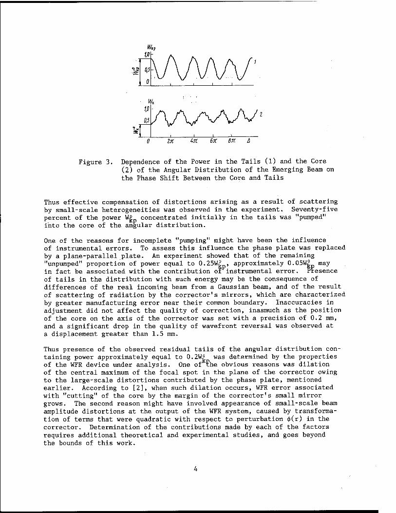
The effect of the phase shift contributed by the Fourier corrector between the core and the tails of the angular distribution upon the power of the emerging beam concentrated in the tails was studied in experiments. For this purpose a linearly varying voltage was applied by a piezoelectric drive, and the dependence of radiation power in the measuring channels on mutual displace- ments of the corrector's mirrors was recorded. The results are shown in Figure 3. At a phase shift equal to zero, the power of radiation in the tails W£ exceeds the power in the core W£ by a factor of 1.3. This means that in the absence of correction, 57 percent of the total power of the incoming beam is scattered into the tails in response to passage through the phase plate twice. In this case Strel's number is S=W£/(W£+W£p)=0.43. As the phase shift increases, the power scattered into the tails varies with a period of 2IT, attaining a minimum of around 0.25W£ at displacements that are multiples of ir(2m+l). The power in the core W^ varies oppositely in phase with Wjjp. This indicates periodic "pumping" of energy from the tails into the core and back as the phase shift increases. (Presence of high frequency pulsations in curve 2 are caused by noise produced by the power measuring unit, which is operating in its most sensitive range.) The maximum payoff in power con- centrated in the core is equal to 2, which corresponds to attaining S=0.86.
WK w 0,5
0 lit Uül 6X BJC
Figure 3. Dependence of the Power in the Tails (1) and the Core (2) of the Angular Distribution of the Emerging Beam on the Phase Shift Between the Core and Tails
Thus effective compensation of distortions arising as a result of scattering by small-scale heterogeneities was observed in the experiment. Seventy-five percent of the power W£ concentrated initially in the tails was "pumped" into the core of the angular distribution.
One of the reasons for incomplete "pumping" might have been the influence of instrumental errors. To assess this influence the phase plate was replaced by a plane-parallel plate. An experiment showed that of the remaining "unpumped" proportion of power equal to 0.25W£ , approximately 0.05WjL may in fact be associated with the contribution of instrumental error. Presence of tails in the distribution with such energy may be the consequence of differences of the real incoming beam from a Gaussian beam, and of the result of scattering of radiation by the corrector's mirrors, which are characterized by greater manufacturing error near their common boundary. Inaccuracies in adjustment did not affect the quality of correction, inasmuch as the position of the core on the axis of the corrector was set with a precision of 0.2 mm, and a significant drop in the quality of wavefront reversal was observed at a displacement greater than 1.5 mm.
Thus presence of the observed residual tails of the angular distribution con- taining power approximately equal to 0.2W° was determined by the properties of the WFR device under analysis. One of the obvious reasons was dilation of the central maximum of the focal spot in the plane of the corrector owing to the large-scale distortions contributed by the phase plate, mentioned earlier. According to [2], when such dilation occurs, WFR error associated with "cutting" of the core by the margin of the corrector's small mirror grows. The second reason might have involved appearance of small-scale beam amplitude distortions at the output of the WFR system, caused by transforma- tion of terms that were quadratic with respect to perturbation cj>(r) in the corrector. Determination of the contributions made by each of the factors requires additional theoretical and experimental studies, and goes beyond the bounds of this work.

Let us now examine a problem of practical interest—the possibility of compensating for small-scale phase distortions arising when transmission occurs through a heterogeneous medium of finite length. This case differs from that examined above in that a beam that passes through heterogeneities located some distance away from the input plane of the WFR device (the plane in which the phase plate was positioned) may experience small-scale spatial modulation of intensity by the moment it enters the device. The device examined here shifts by tr the phase of all angular components outside the bounds of the corrector's small mirror, irrespective of whether these components came into being as a result of phase or amplitude modulation of the field in the cross section of the incoming beam. Thus in contrast to an ideal WFR mirror, it also reverses the small-scale structure of intensity, replacing the intensity maximums by their minimums. From the standpoint of compensating for the influence of long small-scale heterogeneities, this effect is harmful. It must make a small contribution in the case where the input plane of the WFR system is positioned a distance I from any point of the heterogeneous medium which is less than the distance p2/X at which phase heterogeneities transform into amplitude heterogeneities. An additional experiment confirmed these ideas. As was anticipated, shifting of the phase plate from the plane of the image caused a drop in the proportion of energy in the tails that was "pumped" into the core of the angular distribution, such that this proportion was halved at a displacement of £0=0.75p
2/A. This property of the system under examination here is apparently the most significant factor limiting its practical use as a means of compensating for the influence of small-scale heterogeneities of some length. It should be noted, however, that in a number of applications the condition l<l0 may be satisfied. Thus for example, in the case where p=5 mm and X=3 u, Z0-6 m.
Thus the possibility of effective compensation of small-scale distortions in the wavefront of laser radiation having a depth <A/4 by means of a WFR operation effected without utilizing nonlinear elements was experimentally demonstrated in this work. As our evaluations show, in a number of cases use of this system can raise the axial brightness of a laser by several orders of magnitude.
BIBLIOGRAPHY
.1 H 1. Sherstobitov, V. Ye., in "Tez. dokl. IV Vses. konf. 'Optika lazerov' [Abstracts of Reports of the Fourth All-Union Conference "Laser Optics"], Leningrad, Izd-vo GOI, 1983, p 193.
2. Sherstobitov, V. Ye., KVANTOVAYA ELEKTRONIKA, Vol 12, 1985, p 91.
3. Soroko, L. M., "Osnovy golografii i kogerentnoy optiki" [Principles of Holography and Coherent Optics], Moscow, Nauka, 1971.
COPYRIGHT: Izdatelstvo "Radio i svyaz", Kvantovaya elektronika", 1985
11004 CSO: 1862/129

LASERS
UDC 621.373.826.038.823
REPETITIVELY PULSED AND CONTINUOUS WAVE C02 LASERS PUMPED BY A PULSED SELF- SUSTAINED DISCHARGE FOR THERMAL PROCESSING
Moscow KVANTOVAYA ELEKTRONIKA in Russian Vol 12, No 12, Dec 85 (manuscript received 26 Mar 85) pp 2467-2470
[Article by Drobyazko, Yu. V. Pavlovich and Yu. M. Senatorov, Institute of Atomic Energy imeni I. V. Kurchatov, Moscow]
[Text] The design and characteristics of the radiation from fast-flow repetitively pulsed (power up to 3.5 kW) and continuous wave (up to 1.8 kW) C02 lasers excited by a pulsed self-sustained discharge are described. A laser pulse duration of up to 5 msec is attained and continuous modulated radiation is achieved for the first time by exciting the active medium with short (1-3 usec) discharge pulses. Examples of using such a laser in thermal processing are presented.
1. Introduction
In contrast to steady-state lasers, repetitively pulsed C02 lasers make it possible to regulate not only the mean lasing power by means of the pulse repetition frequency but also the pulse power by changing the energy and duration of the laser pulse. In this case the pulse power may exceed the laser's mean power by several orders of magnitude. As is demonstrated in [1,2], the effectiveness with which radiation from a pulsed C02 laser inter- acts with the target depends strongly on the laser pulse duration: At shorter laser pulses (around 1 usec) the optical breakdown plasma effectively shields the target from incident radiation.
Creation of high-power Ul kW) repetitively pulsed C02 lasers with a long laser pulse (20-500 usec) [3-5] and use of these lasers for welding [3,6] and hole drilling [7] demonstrated the high effectiveness and wide capabili- ties of such lasers.
The duration of the laser pulse is increased in [3,5] by reducing the propor- tion of C02, increasing the proportion of nitrogen and decreasing the mixture's total pressure, while in [4] this increase is achieved by displacing the axis of the resonator downward along the flow in relation to the discharge axis.

Pulse energy and laser mean power decrease noticeably in this case. This is why increasing pulse energy and mean power at a pulse duration greater than 100 usec and creation of repetitively pulsed C02 lasers with TpSl msec and a mean power of 1-2 kW is an urgent task.
This paper describes the design and presents the characteristics of laser radiation produced by a repetitively pulsed C02 laser with a mean power of up to 3.5 kW and a pulse duration of 4-5000 usec, excited by short (around 1 usec) pulses of a self-sustained discharge; continuous modulated radiation is obtained from such a laser.
2. The Design of the Laser and the Characteristics of Its Gas-Dynamic Loop
The laser housing is made from stainless steel 6 mm thick, it is cylindrical in shape, and its lateral flanges, which are 20 mm thick, are made from brand D16T duralumin.
The cavity of the cylinder is partitioned by retractable panels forming the laser's gas-dynamic channel. A gas discharge chamber, a heat exchanger, fans and guides that shape the gas-dynamic flow are positioned on the panels. Voltage, electrolyte, water and diagnostic lines are introduced through two fiber glass laminate plates positioned in the upper part of the housing. The resonator block is secured independently and connected hermetically to the chamber through a rubber diaphragm. The design of the adjusting units permits work with stable and unstable resonators, and change in the number of passes from one to five. In work with a stable resonator, a GaAs plate cooled by contact with a polished metal support was used as the exit mirror. The working mixture is pumped through the discharge zone by two aircraft fans, the charac- teristics of which are given in [5]. The fans are turned by 5 kW direct current motors. Low power voltage (27 V) and small dimensions made it possible to install the motors inside the chamber, and presence of an excitation wind- ing makes it possible to smoothly adjust the motor rpm from 3,500 to 9,000. The motor is rigidly connected with the fan, and to reduce vibration the entire structure is secured to a rubber membrane.
An electrode system with a plasma cathode and an ultraviolet pre-ionization working mixture similar to that described in [8] was used to excite a piilsed glow discharge. The structure of the electrode system made it possible^ to excite the active medium both within the entire 100x15x6 cm discharge gap and at half the cathode at gap 6 with a flow width of 7.5 cm. This makes it possible to double the maximum pulse repetition frequency at the same gas mixture flow rate. The rate of the gas flow increases linearly with rpm, being 85 and 120 m/sec when one and two fans are turned on at 9,500 rpm. Variation of flow rate in response to change in pressure and composition of the mixture (p=40-160 mmHg, XC02=1-30 percent) did not exceed 15 percent. As the energy contribution to the discharge increased to 30 kW, the flow rate, which was measured in this case upstream from the discharge, did not change.

3. Characteristics of Laser Radiation
The oscillation mode in the case of work with a stable resonator was multimode, and divergence at the 0.84 level varied from 2 to 4 mrad depending on the number of passes. In work with an unstable resonator, divergence better than 1 mrad was achieved. This made it possible to obtain a power density from 105 to 109 W/cm2 in the spot using standard focusing systems (lenses, mirrors).
W.KST „ (1)
Ü),
Figure 1. Dependence of Radiation Mean Power on Pulse Repetition Frequency When p=120 mmHg, xp=30 usec, v=90 m/sec in a C02:N2:He=17:25:58 Mixture for Discharge Volumes of 100x15x6 (1) and 100x7.5x6 cm (2)
Key: kW Hz
As the pulse repetition frequency grows, mean power increases linearly until f=fkp, where fu is frequency depending on the relative energy contribution, the gas flow rate, the width of the discharge along the flow and the resistance of the discharge to gas-dynamic perturbations. As a rule, fw is two to five times less than the rate of gas replacement in the discharge gap. Figure 1 shows the dependence of mean power on frequency in the case of excitation of the entire discharge volume (curve 1) and half of it (2). Doubling of the gas replacement frequency in the discharge zone made it possible to almost double fw,. The decrease in the maximum mean power in the second case is explained by nonoptimum operation of the resonator. In our experiments f^p was twice less than the rate of gas replacement in the discharge zone. At a frequency f>fkp mean power falls, and the stability of the discharge and of laser action are achieved through a decrease in the energy contribution to the discharge. When f=l kHz (curve 1), laser action was achieved by superimposing two discharge pulses on the same portion of gas.
As is demonstrated in [1-3,6], the effectiveness with which pulsed and repetitively pulsed C02 laser radiation interacts depends strongly on laser pulse duration. Mean power and duration of laser pulses were measured in
relation to different mixtures (He=50%, C02=2-30%, N2=20-48%) and pressure variation from 20 to 160 mmHg, and the dependence of mean power on laser pulse duration was plotted.
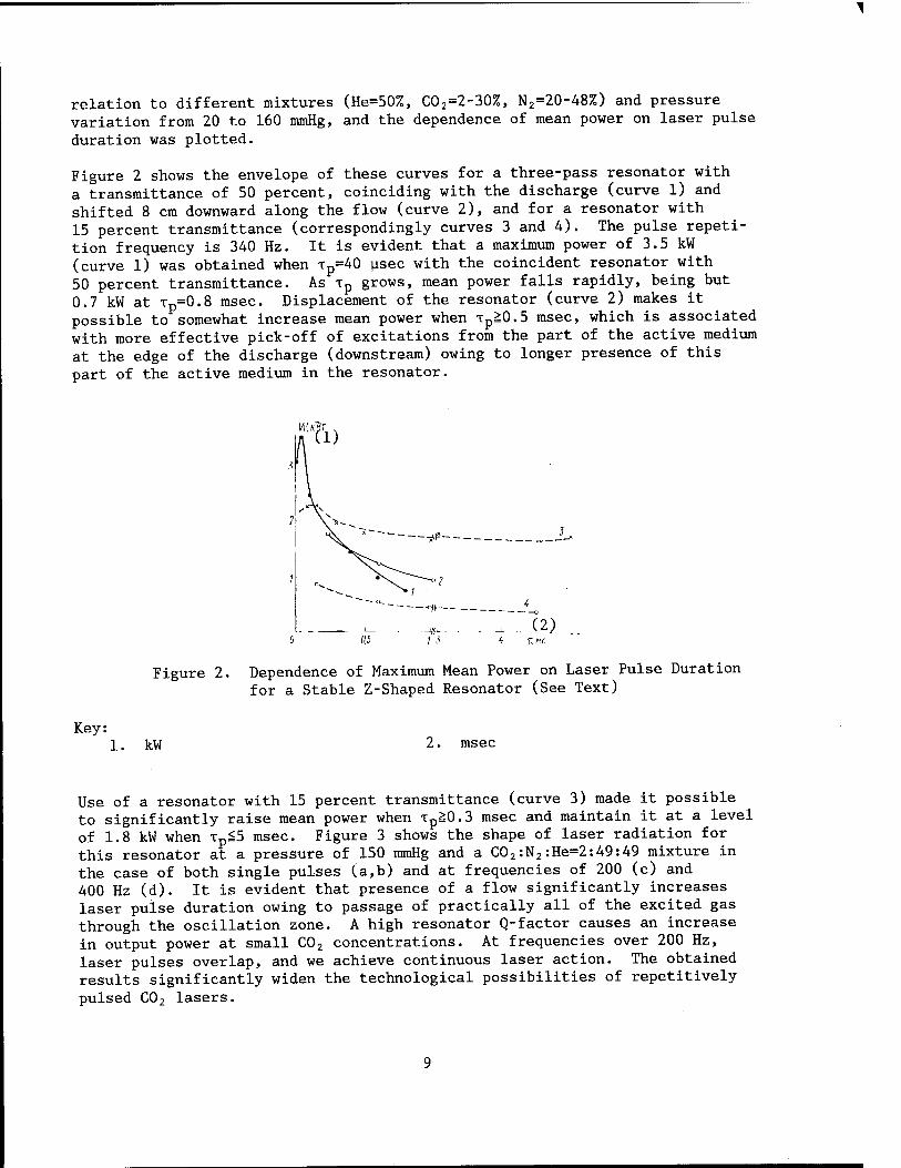
Figure 2 shows the envelope of these curves for a three-pass resonator with a transmittance of 50 percent, coinciding with the discharge (curve 1) and shifted 8 cm downward along the flow (curve 2), and for a resonator with 15 percent transmittance (correspondingly curves 3 and 4). The pulse repeti- tion frequency is 340 Hz. It is evident that a maximum power of 3.5 kW (curve 1) was obtained when tp=40 usec with the coincident resonator with 50 percent transmittance. As xp grows, mean power falls rapidly, being but 0.7 kW at Tp=0.8 msec. Displacement of the resonator (curve 2) makes it possible to somewhat increase mean power when Tp£0.5 msec, which is associated with more effective pick-off of excitations from the part of the active medium at the edge of the discharge (downstream) owing to longer presence of this part of the active medium in the resonator.
Figure 2. Dependence of Maximum Mean Power on Laser Pulse Duration for a Stable Z-Shaped Resonator (See Text)
Key: kW msec
Use of a resonator with 15 percent transmittance (curve 3) made it possible to significantly raise mean power when xp&0.3 msec and maintain it at a level of 1.8 kW when xpS5 msec. Figure 3 shows the shape of laser radiation for this resonator at a pressure of 150 mmHg and a C02:N2:He=2:49:49 mixture in the case of both single pulses (a,b) and at frequencies of 200 (c) and 400 Hz (d). It is evident that presence of a flow significantly increases laser pulse duration owing to passage of practically all of the excited gas through the oscillation zone. A high resonator Q-factor causes an increase in output power at small C02 concentrations. At frequencies over 200 Hz, laser pulses overlap, and we achieve continuous laser action. The obtained results significantly widen the technological possibilities of repetitively pulsed C02 lasers.

( a)
■illHgHHI ■SUSHI
Figure 3. Shapes of a Laser Pulse for a Stable Three-Pass Resonator Coinciding with the Discharge (R=85%) at v=0 (a) and 70 m/sec (b-d) (See Text)
Key: 1. msec
Figure 4. Examples of Using a Repetitively Pulsed C02 Laser in Thermal Processing: a--penetration of Khl8N10T steel, h=12 mm, xp=50 usec, f=250 Hz, W=1.5 kW, v=0.2 mm/sec; b--cavities in Khl8N9T steel, f=200 Hz, Tp=100 usec, W=l kW, total number of pulses 250 and 500; c--strengthen- ing zone in brand 45 steel, hmax=0.65 mm, f=200 Hz, W=l kW, T=150 usec, ray diameter on surface 3 mm, rate of movement of article 6 mm/sec, hardness HV=700
4. Possible Uses of Repetitively Pulsed C02 Lasers
Figure 4 shows photographs of a penetration, a hole and a tempered zone on brand 45 steel obtained with the described laser. Note that at low target
10
speeds (around 0.1 mm/sec), record-low relative power outlays were obtained per unit of seam depth (40 W/mm) at a seam depth to mean width ratio of 25. By varying the laser operating mode we can adjust the diameter of the hole from 0.03 to 2 mm, and the depth of the hole from 0.1 to 24 mm. The time it takes to drill a hole with a diameter of 0.8 mm and h=6 mm is around 1 sec at a laser mean power of 2 kW.
The hardness of the tempered layer is somewhat greater than in the case of tempering with a continuous wave laser, and maximum depth is 0.65 mm.
Thus a repetitively pulsed C02 laser with a mean power of up to 3.5 kW and a pulse duration from 4 to 5000 usec has been created. For the first time continuous oscillation was achieved with a fast-flow repetitively pulsed laser using short (1-3 usec) discharge pulses to excite the active medium. Examples of industrial uses of the laser are presented.
BIBLIOGRAPHY
1. Hamilton, D. C. and Pashby, I. R., OPT. LASER TECHN., Vol 8, 1979, p 183.
2. Vedenov, A. A., Gladush, G. G., Drobyazko, S. V. and Senatorov, Yu. M., KVANTOVAYA ELEKTRONIKA, Vol 8, 1981, p 2154.
3. Levin, G. I., SVAROCHNOYE PROIZVODSTVO, Vol 9, 1980, p 29.
4. Velenov, A. A., Drobyazko, S. V. and Korzinkin, M. M., KVANTOVAYA ELEK- TRONIKA, Vol 7, 1980, p 1186.
5. Generalov, N. A., Zimakov, V. P., Kosynkin, V. D., Rayzer, Yu. P. and Solovyev, N. G., KVANTOVAYA ELEKTRONIKA, Vol 9, 1982, p 1549.
6. Vedenov, A. A., Gladush, G. G., Drobyazko, S. V. and Levchenko, Ye. B., IZV. AN SSSR. SER. FIZICH., Vol 47, 1983, p 1473.
7. Borkin, A. G., Vedenov, A. A., Gladush, G. G., Drobyazko, S. V., Pavlovich, Yu. V. and Senatorov, Yu. M., "Tez. dokl. na Mezhotraslevoy nauchno- tekhnicheskoy konferentsii 'Vzaimodeystviye izlucheniya, plazmennykh i elektronnykh potokov s veshchestvom"' [Abstracts of Reports at the Intersector Scientific-Technical Conference "Interaction of Radiation and Plasma and Electron Fluxes with Matter"], Moscow, 1984, p 95.
8. Drobyazko, S. V. and Zhuravskiy, A. G., KVANTOVAYA ELEKTRONIKA, Vol 6, 1979, p 49.
COPYRIGHT: Izdatelstvo "Radio i svyaz", Kvantovaya elektronika", 1985
11004 CSO: 1862/129
11

LASERS
UDC 621.373.826.038.823
ACTIVE MEDIUM FORMATION IN LASERS USING MIXTURES OF INERT GASES AND OPTICAL BREAKDOWN PUMPING
Moscow KVANTOVAYA ELEKTRONIKA in Russian Vol 12 No 12, Dec 85 (manuscript received 18 Jul 85) pp 2389-2391
[Article by V. V. Apollonov, S. I. Derzhavin, A. M. Prokhorov and A. A. Sirotkin, Institute of General Physics, USSR Academy of Sciences, Moscow]
[Text] The parameters of the active medium of lasers using He-Xe (X=2.03 and 2.65 u) and He-Ar (X=1.79 u) gas mixtures and pumping by optical breakdown by C02 laser radiation are analyzed. It is demonstrated that laser action arises as a result of the joint action of UV radiation and the shock wave formed in response to optical breakdown.
Optical breakdown is used to pump the active medium of lasers owing to the prospects of achieving laser action in the far UV range. Lasers using optical breakdown pumping and operating in the IR and visible ranges are known to exist [1-4], Nonetheless the mechanisms responsible for formation of inversion in such active media have not yet been studied sufficiently. Thus it was asserted in [1,2,4] that inversion of the population in lasers using inert gas mixtures occurs in recombining optical breakdown plasma when the plasma disperses into the surrounding buffer gas. However, detailed research on active medium parameters that could confirm this mechanism with certainty was not carried out.
We analyzed the mechanisms behind formation of an inversion in lasers using inert gas mixtures pumped by optical breakdown. For this purpose we conducted interferometric and spectroscopic research on the parameters of the active media of He-Xe (A=2.03 u) and He-Ar (A=1.79 u) lasers.
The experimental set-up (Figure 1) is described in [4,5]. In our experi- ments the length of the plasma band I was increased to 9 cm. The parameters of the active medium were studied by the method of double-exposure holo- graphic interferometry. A ruby laser with a radiation pulse duration of x-20 nsec was used as the light source in the interferometer. Interferograms of the laser plasma were recorded with a variable delay At relative to the moment of appearance of optical breakdown near the target.
12

^ -Bf
/ 0
■fl-s
■b
Figure 1. Diagram of Experimental Set-Up: l--ruby laser; 2-- cylindrical lens; 3--focusing optics; 4--light divider; 5--wedge; 6--photographic plate; 7--diaphragm 0 1 mm; 8--aluminum target; 9- 11--L1F plate
-Ge:Au receiver; 10--C02 laser;
Comparison of the laser action parameters of the plasma laser and the results of interferometric analysis of its active medium showed that the moment of appearance of laser action coincides with the moment that a Shockwave reaches the region of the resonator's caustic, while the optical breakdown plasma does not attain the region of laser action, and thus it cannot participate directly in inversion formation.
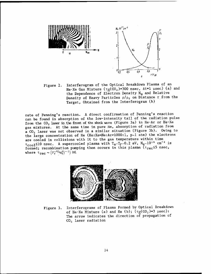
The experimental dependencies of the radius of the shock wave on time arrived at in this work agree well with the model of a cylindrical point explosion [7]. This made it possible to account for the contribution of heavy particles to refraction of the plasma and to determine shock wave parameters when processing the interferograms. Figure 2 shows an interferogram for At=l usec corresponding to the start of the oscillation pulse of the plasma laser, and the density distribution of electrons Ne and gas p calculated on the basis of the latter. The low gas temperature behind the shock wave's front Tr~0.2 eV shows that the shock wave cannot serve directly as an active medium pumping source; nor, all the more so, can it be the cause of formation of a significant electron concentration, Ne~10
16 cm-3.
It is well known that in lasers using gas mixtures containing helium, the active medium is formed as a result of Penning1s reaction between a working
Kn atom and excited helium [6]. For example He* + Xe—>-Xe++He + e. In this case the rate of Penning's reaction R=KnNue*Nxe depends on the gas temperature [6,9] and the concentration of particles participating in the reaction %e*> ^Xe- 1° our experiments presence of excited atoms before the front of the shocK wave was confirmed by luminescence of the Hel, Xel and Xell lines. In particular these lines may have formed as a result of diffusion of resonant UV radiation [7] from the hot core of the optical breakdown plasma. The long delay in laser action makes it possible to suggest that atoms in excited state with a long life span participate in inversion formation.
The increase in concentration of interacting particles (at a degree of compression r)=p/Po=4) and heating of the gas to a temperature of Tr~0.2 eV occurring with the advent of the shock wave cause a sharp increase in the
13
Ne,10ncM~3
Figure 2. Interferogram of the Optical Breakdown Plasma of an He-Xe Gas Mixture (TH(C02)=300 nsec, At=l usec) (a) and the Dependence of Electron Density Ne and Relative Density of Heavy Particles p/p0 on Distance r from the Target, Obtained from the Interferogram (b)
rate of Penning1s reaction. A direct confirmation of Penning's reaction can be found in absorption of the low-intensity tail of the radiation pulse from the C02 laser in the front of the shock wave (Figure 3a) in He-Ar or He-Xe gas mixtures. At the same time in pure He, absorption of radiation from a C02 laser was not observed in a similar situation (Figure 3b). Owing to the large concentration of He (He:Xe=He:Ar=1000:1, p~l atm) the electrons are cooled in collisions with it to the gas temperature within time Tcool=10 nsec- A supercooled plasma with Te~Tr~0.2 eV, Ne~10
16 cm-3 is formed; recombination pumping then occurs in this plasma (xrec=
5 nsec> where Trpn ~ {TJ'I'NI)-
1) [8]'. Lrec
Figure 3. Interferograms of Plasma Formed by Optical Breakdown of He-Xe Mixture (a) and He (b); (TH(C02)=3 usec): The arrow indicates the direction of propagation of C02 laser radiation
14

Note also that laser action was observed at a fixed distance, for the given conditions, from the axis of the plasma band along every generatrix of the cylindrical front of the shock wave (figures 2,3). This indicates cylindrical symmetry of the physical conditions, and it may serve as a confirmation of the plausibility of using the model of a cylindrical point explosion.
To confirm the above-described mechanism behind formation of the active medium we conducted experiments in which the gas mixture was additionally illuminated by UV radiation from a spark electric discharge. In the presence of illumination activated simultaneously with the appearance of optical breakdown, the threshold energy of the C02 laser at which laser action is still observed in an He-Xe laser, decreases significantly (by a factor of 1.5 at a discharge energy of Ep~EH(C02)~A J). In this case the delay between the appearance of optical breakdown and laser action remained practically constant. Thus UV radiation from the plasma does in fact play a significant role in formation of the active medium. At the same time, a large At~l usec and constancy of the delay in laser action in the presence of additional UV illumination indicate that the inversion forms when the gas mixture is compressed by the shock wave.
Thus, appearance of laser action in inert gas mixtures subjected to pumping by optical breakdown may be explained by the joint influence of UV radia- tion and the shock wave on the gas mixture. The proposed system makes it possible to explain the experimental dependencies obtained in [1,2,4].
The authors acknowledge G. R. Toker and A. V. Borovskiy for their useful discussion and help in the experiment.
BIBLIOGRAPHY
1. Silfwast, W. T., Szeto, L. H. and Wood, 0. R., II, J. APPL. PHYS, Vol 50, 1979, p 7921.
2. Danilychev, V. A., Zvorykin, V. D., Kholin, I. V. and Chugunov, A. Yu., KVANTOVAYA ELEKTRONIKA, Vol 9, 1982, p 22.
3. Wood, 0. R., II, Macklin, J. J. and Silfwast, W. I., APPL. PHYS. LETTS, Vol 44, 1984, p 1123.
4. Apollonov, V. V., Bunkin, F. V., Derzhavin, S. I., Prokhorov, A. M., Sirotkin, A. A. and Firsov, K. N., KVANTOVAYA ELEKTRONIKA, Vol 11, 1984, p 1757.
5. Apollonov, V. V., Akhunov, N., Derzhavin, S. I., Kononov, I. G., Sirotkin, A. A., Firsov, K. N. and Yamshchikov, V. A., KVANTOVAYA ELEKTRONIKA, Vol 10, 1983, p 1929.
6. "Plazma v lazerakh" [Plasma in Lasers], Moscow, Energoizdat, 1976.
15

7. Zeldovich, Ya. B. and Rayzer, Yu. P., "Fizika udarnykh voln i vysokotem- peraturnykh gidrodinamicheskikh yavleniy" [Physics of Shock Waves and High-Temperature Hydrodynamic Phenomena], Moscow, Nauka, 1966.
8. Gudzenko, L. I. and Yakovlenko, S. I., "Plazmennyye lazery" [Plasma Lasers], Moscow, Atomizdat, 1978.
9. Yeletskiy, A. V. and Smirnov, B. M., "Fizicheskiye protsessy v gazovykh lazerakh" [Physical Processes in Gas Lasers], Moscow, Energoatomizdat, 1985.
COPYRIGHT: Izdatelstvo "Radio i svyaz", Kvantovaya elektronika", 1985
11004 CSO: 1862/129
16

LASERS
UDC 621.373.826.038.823
EFFECT OF 'CLARIFYING' THE ATMOSPHERE IN RELATION TO QUASI-MONOCHROMATIC C02 LASER RADIATION
Moscow KVANTOVAYA ELEKTRONIKA in Russian Vol 12 No 12, Dec 85 (manuscript received 18 Mar 85) pp 2505-2507
[Article by N. F. Borisova, V. M. Osipov and N. I. Pavlov]
[Text] The effect of the finite width of a C02 laser line on radiation transmission on an atmospheric path is investi- gated. Numerical calculations are used to demonstrate that an increase in the half-width of the lasing line to several hundredths of an inverse centimeter makes it possible to significantly improve transmission of laser radiation through the atmosphere (for a vertical path from the earth surface to the upper boundary of the atmosphere, transmission may almost double in comparison with monochromatic radiation). An increase in transmission caused by detuning of the lasing line from the resonant absorption line is also enhanced when the finite width of the lasing line is taken into account.
As it propagates through earth atmosphere, laser radiation is attenuated owing to absorption by air molecules and aerosol particles. There is important practical significance to studying the possible ways of improving trans- mission of laser radiation through the atmosphere. Inasmuch as molecular absorption has a clearly pronounced selective nature, attenuation of laser radiation may be changed significantly by, for example, shifting the lasing line frequency relative to the absorption lines of atmospheric gases. The effect of shifting lasing lines on transmission was assessed in a number of works (see for example [1]). But in these works--and incidentally in practi- cally all works in which attenuation of laser radiation in the atmosphere is calculated [1,2]--laser radiation is assumed to be strictly monochromatic. An exception is a recently published work [3] in which an approximate formula is obtained for transmission of narrow-band laser radiation, and in which the conditions governing the applicability of the monochromatic approximation for evaluating transmission of laser radiation on a homogeneous (horizontal) atmospheric path are determined on the basis of this formula.
In high pressure C02 lasers the width of the emission line may exceed several hundredths of an inverse centimeter (see for example [4]), which is comparable
17

with the widths of the absorption lines of atmospheric gases on a surface path, and significantly greater than the latter in the upper layers of the atmosphere. In this case the supposition of strict monochromaticity of laser radiation is not always valid, and it would be interesting to assess the influence of this effect on transmission of laser radiation through the atmosphere.
We know that attenuation of C02 radiation in the region around 10.6 u stems basically from resonant absorption in the lines of atmospheric carbon dioxide, as well as from continual absorption by water vapor. It would be natural to expect that widening of the emission line would lead to a decrease in resonant absorption (given constant continual attenuation). The objective of this paper is to obtain numerical estimates of this "clarification" effect in relation to homogeneous (horizontal) and heterogeneous (vertical) atmo- spheric paths. ("Clarification" is defined as increasing transmission of radiation through the atmosphere by means of the described mechanism while maintaining the atmosphere itself constant.) We will briefly describe the procedure for calculating transmission of quasi-monochromatic C02 laser radia- tion in the region around 10.6 u (the half-width of the emission line can serve as a measure of quasi-monochromaticity), and we will present some results of numerical calculation of the influence of the finite width of the C02 laser line and its detuning from the resonant absorption line on atmo- spheric transmission below.
Transmission in relation to quasi-monochromatic radiation may be written in the form
rA* = THl0 (v.) jv d v g (v - v.) TCOi (v), (I)
where g(v-v0)--function normalized to unity describing the contours of an emission line with its center at frequency v0; Av--spectrum interval in which g(v-v0) is different from zero. Monochromatic transmission TC02(v) i-n formula (1), which corresponds to resonant absorption of radiation by atmospheric carbon dioxide, is described by known expressions, which have the following form in relation to horizontal and vertical atmospheric paths:
fco. (v) =
exp[-£COa(v, z) L];
(2) exp — J *co,(v. 2">dz'
The absorption coefficient at height z is determined by the expression
feco, (v- z> = s <z>-/ (v - vo • V (z)) "co. (z). (3)
where S and f--intensity and shape of the contour of an absorption line with its center at frequency v'0; ^(z)--set of parameters characterizing this
18

contour; uco2"-concentration of carbon dioxide. Transmission TJI2O(V0) in (1), which corresponds to continual absorption of radiation by water vapor, may be described by expressions of the form (2) with an absorption coefficient kjj o(vo>z) given, for example, by the approximation formula suggested in [5]. The atmospheric "clarification" effect is determined by the variable
T) = T^/T (v0) = rco>, Av/rc0, (v0) (4>
and it does not depend on continual attenuation.
In the numerical calculations of TAv and n, (Foygt's) function was used to describe the contour of the absorption line, and the contour of the emission line was defined by a Gaussian function. The parameters of the absorption lines were taken from [6]. During integration in (2) with respect to the height of the concentration of absorbing gases, the temperature and pressure at level z were determined by polynomial interpolation of the appropriate tables serving as standard models of the atmosphere (the dependencies presented in the figures below correspond to the model for a mid-latitude summer) [7].
_
/l -SUM
/ 30 /"~ / ffl.
\*r 1 1 ._ i I
« U,.M''
Figure 1. Dependence of n on the Half-Width yna3 of the Emission Line P20
12C1602 for a Horizontal Path with Length L=50 (a) and 100 km (b) at Height z (6=0)
Figure 2. Dependence of Transmission TAv on a Vertical Path from Level z=0 to the Upper Boundary of the Atmosphere on the Half-Width ■xna3 of the Emission Line P22
12C1602 at Different Magnitudes of Detuning 6
19

Numerical calculations were used to study the dependence of T^v and r\ on the half-width Y^a3 °f tne emission line of a C02 laser; the contour of the emission line g(v-v0) was assigned a particular shape. Moreover the dependence of transmission T^v on the half-width of the lasing line was determined in relation to the case where the position of the lasing line v0 does not coincide with the center v'Q of the absorption line. The calculations were made for different magnitudes of detuning <5=v0-Vo lying within the range 6= =0-0.03 cm"1. Horizontal paths with length L=50 and 100 km at heights z=5, 10 and 30 km and vertical paths from level z=0 to the upper boundary of the atmosphere were examined. The results of the numerical calculations are illustrated in figures 1 and 2.
The research permits the following conclusions:
1. Use of C02 lasers with a lasing line half-width of several hundredths of an inverse centimeter as radiation sources makes it possible to significant- ly improve transmission of laser radiation through the atmosphere (by almost twice for a vertical path for which 6=0 and Yjia3=P*l cm_1)-
2. The transmission of atmospheric paths in relation to fixed magnitudes of detuning from the frequency of the resonant absorption line increases with the width of the lasing line.
3. It may be expected that consideration of the real (that is, nonmonochroma- tic and, in a number of cases, non-Gaussian) shape of the C02 laser line in relation to certain paths and sufficiently wide lasing lines would lead to noticeable reduction of losses caused by thermal defocusing of radiation owing to a noticeable reduction of absorption of laser radiation in the resonant absorption lines of atmospheric C02.
Use of different isotope modifications of the carbon dioxide molecule in C02 lasers also makes it possible to increase the transmission of atmospheric paths. Calculation of monochromatic transmission on a vertical atmospheric path in relation to line P20 of
1ZC1802 (v=l,068.942 cm-1) and 13C1602 (v=
=896.909 cm"1) isotopes and in relation to the same conditions of a mid- latitude summer produce values of 0.61 and 0.67 respectively. However, in our opinion this method of controlling the radiation spectrum of a C02 laser is disadvantageous in comparison with that described above due to the high cost of carbon dioxide isotopes.
BIBLIOGRAPHY
1. Sutton, G. W. and Douglas-Hamilton, D. H., APPL. OPTICS, Vol 18, 1979, p 2323.
2. Kelley, P. L., McClatchey, R. A., Long, R. K. and Snelson, A., OPT. QUANT. ELECTRON., Vol 8, 1976, p 117.
3. Mitsei, A. A., Ponomarev, Yu. I. and Firsov, K. M., IZV. AN SSSR. SER. FIZ. ATM. I OKEANA, Vol 20, 1984, p 327.
20

A. Ageykin, V. A., Bagratashvili, V. N., Knyazev, I. N., Kudryavtsev, Yu. A. and Letokhov, V. S., KVANTOVAYA ELEKTRONIKA, Vol 1, 1974, p 334.
5. Arefyev, V. N., Pogadayev, B. N. and Sizov, N. I., KVANTOVAYA ELEKTRONIKA, Vol 10, 1983, p 496.
6. Rothman, L. S., APPL. OPTICS, Vol 20, 1981, p 791.
7. McClatchey, R. A., Fenn, R. W., Selby, J. E. A., Volz, F. E. and Garing, J. S., "Optical Properties of the Atmosphere," AFCRL Report 72-0497, 1972.
COPYRIGHT: Izdatelstvo "Radio i svyaz", Kvantovaya elektronika", 1985
11004 CSO: 1862/129
21
LASERS
UDC 621.373.826
LASERS WITH WAVEFRONT-REVERSING MIRRORS (REVIEW ARTICLE)
Moscow KVANTOVAYA ELEKTRONIKA in Russian Vol 12 No 12, Dec 85 pp 2394-2421
[Article by I. M. Beldyugin, B. Ya. Zeldovich, M. V. Zolotarev and V. V. Shkunov]
[Text] The design principles of lasers with wavefront reversing mirrors are examined. Methods of determining the transverse and longitudinal mode structure in these lasers are described. The advantages and shortcomings of different systems with WFR mirrors are analyzed, and they are compared with each other and with conventional lasers. The trends and basic directions of further research are discussed.
1. Introduction
In this review we will discuss a question which has attracted a large number of researchers in the last few years. We are referring to lasers in which one of the mirrors is replaced by an element that reverses the wavefront (the WFR mirror) [1-7J. Increasing the axial brightness of laser radiation is associated in many ways with eliminating the influence of optical hetero- geneities in the index of refraction of the amplifying medium. As a rule these heterogeneities are small in scale, and they vary irregularly in space and in time. In this situation optical heterogeneities of the medium may be compensated only by using WFR methods.
Interest in lasers with WFR mirrors results from the fact that they possess properties that make them significantly different than lasers with conven- tional mirrors. The most important difference is that compensation of intra- resonator aberrations is possible under certain conditions in WFR mirror lasers. It should also be noted, however, that a resonator equipped with a WFR mirror has a transverse mode structure similar to a confocal resonator equivalent to it (and consequently the same selective properties). Therefore as with the latter, an angle selector must be installed in it in order to isolate one lowest transverse mode (a supermode laser insures high direction- ality of the laser radiation). A WFR resonator is significantly different from a conventional one in that when a medium with a heterogeneous index of refraction is introduced into the resonator, the angle selector in the WFR resonator does not introduce additional losses. The objective of obtaining
22

supermode operating conditions predetermines the importance of calculating the transverse mode structure in WFR mirror resonators with limiting diaphragms.
Another distinguishing property is high stability of the frequency spectrum of generated radiation which is determined by the stability of the spectrum of reference waves for a WFR mirror based on four-wave mixing, and which depends slightly on the distance between the WFR mirror and the exit mirror. Thus, a laser lasing at the central frequency of the amplification loop of an active medium would continue to generate at the same frequency irrespec- tive of changes in the resonator's length [8,9].
The importance of studying lasers with WFR mirrors is also determined by the fact that this system is precisely what may be the variant that will resolve the difficulties associated with the WFR method (formation of high quality reference and priming waves, effective use of energy stored in the medium, synchronization of the reference and signal waves, stability of the spectrum and so on).
The objective of this review is to not only systematize and analyze existing results, but also to assess the further prospects of using WFR mirrors to create lasers emitting highly directional radiation.
The entire diversity of lasers may be subdivided, based on the type of WFR mirror, into four basic groups: lasers with a WFR mirror based on four- wave mixing (WFR-FWM); with an SBS mirror; with a retromirror effecting pseudorotation, and with an adaptive mirror. The review will devote the greatest attention to the first and third groups, which have been studied most completely to date.
2. Lasers with FWM Mirrors
In terms of the method used to create reference waves, lasers with FWM mirrors are subdivided into lasers with an external source of reference waves and with a self-pumping FWM mirror [10].
The design of lasers with an external source of reference waves, diagrammed in Figure 1, is similar to the design of conventional lasers with the exception that a conventional mirror is substituted by a FWM mirrorj in which reference waves are formed by an external source. Such a laser is extremely ineffective, because the required pumping power usually exceeds the power . of the exit radiation of the WFR mirror. However, because of their relative simplicity, such lasers can be used as an example to reveal the characteristic features of WFR mirror lasers.
Lasers with a self-pumping FWM mirror do not require a separate additional source of two intensive complexly conjugated reference waves. Part of the radiation withdrawn from the laser exit is used as the pumping radiation; it propagates through a nonlinear medium twice in opposite directions. The simplest design of such a laser is shown in Figure 2; other possible designs
23

Figure 1. Laser with an FWM Mirror with an External Source of Reference Waves: l--exit mirror; 2--active medium; 3--FWM medium; 4--pumping laser
Figure 2. Laser with Self-Pumping FWM Mirror: 4--exit mirror; 5--active medium; 6- 7--opto-electronic switch
l-3--mirrors; -FWM medium;
of lasers with a self-pumping WFR mirror will be described below (see figures 9,12). For amplifying media characterized by a high gain (over 102
per pass) and considerable heterogeneities in the index of refraction, a resonator with a self-pumping WFR mirror insures the greatest effectiveness of the entire laser system [11].
One of the most important problems arising in laser research is that of determining the form of the fields, the types of oscillations and the corre- sponding frequencies and losses. These characteristics are precisely what strongly influence the effectiveness and modal volume of the laser and the divergence of laser radiation. Let us first describe the structure of the longitudinal modes of a WFR-FWM resonator in its simplest design with external pumping of reference waves and without aperture limitations on the mirrors and in the volume of the resonator. Then we will dwell in detail on how aperture limitations and imprecision of the reversal operation of a WFR mirror determine the transverse structure of the modes, and we will study the work of a WFR resonator with a self-pumping FWM mirror.
Next we will concern ourselves chiefly with the frequency and spatial struc- ture of fields in WFR mirror lasers, and therefore we will assume that amplification in one pass compensates for losses in the resonator.
2.1. Structure of Longitudinal Modes of a Resonator with a WFR-FWM Mirror Without Aperture Limitations
First let us examine a WFR mirror based on use of FWM with external reference waves Ex, E2 and frequencies a)1=(jj2
=w0. When a wave from within the resonator
24

U3exp (ik3z-iu)3t) strikes such a mirror, a reflected wave U^exp (-ik^z-ia^t) arises, where U^e1* and w^w«.-«»^ phase 41 is determined by the absolute phase of the product X
(3)EiE2. For crossing reference waves E^xp (-iu0t+ +ikxR) and E2exp (-ico0t+ik2R) with k2=-kx this phase does not depend on spatial coordinates in a nonlinear medium. It is determined by the position of the mirror by which wave E2 is obtained from wave Ex, and it changes by 2w0At when the point of the initial time reading is shifted by At. When a wave U^ propa- gates from a WFR mirror to a conventional mirror and back, it "picks up a phase factor exp (2ik<,L), where L is the length of the resonator. When we examine the modes of a conventional resonator, we limit ourselves to one pass through the resonator, and we equate the resulting field U^ with the initial field U3. We cannot do this here because field U„ has another frequency (10^0)3), and closure requires one more pass through the resonator. When wave U^ is reflected from a WFR mirror, it transforms into wave U3-[Ullexp(2ik,lL)]*e 1 with frequency u>3. Wave U3 passes to the conventional mirror and back, acquiring a phase run-on 2ik3L. Finally, after two complete passes through the resonator we have
Ul = U3exp{2ik3L) = U3exp[2i(k3 — ki)L]' (1)
that is, the field has automatically restored its frequency <D3 and acquired a phase shift 2(k3-kJL=2(W3-UOL/C=4(U>3-U>0)L/C. We emphasize that this phase shift is independent of the phase of the complex coefficient of WFR reflection.
The mode of the resonator is a self-reproducing field. The self-reproduction condition in conventional resonators isolates discrete mode frequencies
2 Lco/c=2 Jtm+O (p, q), (2)
where $(p,q) is the phase depending on transverse indices p,q to which fully defined transverse configurations of modes Mpq(r,z) correspond. Thus in a conventional resonator, the intermodal interval for a given transverse index equals ü)m+1-o)m=2-rr/T, where T=2L/c is the time of complete passage through the resonator, and the absolute position of the frequencies is determined by resonator length L: When it changes, all frequencies are shifted by Au)m=-a)mAL/L.
In accordance with (1), the self-reproduction condition for a resonator with a WFR mirror has the form
4 L (0)3—to0)/c=2 nn, (3)
where n is a whole number. First of all there are modes with n^O consisting of two-frequency fields ü)3n=ü)0+irnc/2L, o)4n=ü)0-TOc/2L, where n>0 and n<0 differ only in relation to which field is called U3 and which is called U^ The intervals between successive frequencies equal ü)n+1-U)n=2ir/2T, where 2T- =4L/c is the time of two complete passages through the resonator; these
25

intervals are half that of a conventional resonator.* It is very important that the absolute frequency of these modes be determined chiefly by the frequency OJ0 of the reference waves, and that it is insensitive to small changes in resonator length: Au)n=(u)0-ü)n)AL/L, which is (u)0-ton)/w0~10
5
times less than for a conventional resonator.
Let us assume that the transverse structures of fields U3(r) and U\(r) of a two-frequency mode (a mode for which n^O) are identical. Then owing to interference between fields U3(r) and U^(r) the temporal course of intensity at the resonator exit has the form / (/)co[l+cos (2 n ntlT)]. When n=l, this corresponds to shifting of the intensity maximum through the resonator from the WFR mirror to the exit mirror and back at the speed of light.
It is noteworthy that when both mirrors (conventional and WFR) are sufficient- ly wide, and no losses depending on the transverse structure of the field occur, fields U3(r) and U^r) have a completely arbitrary shape satisfying only the conditions which associate waves striking and reflected from the WFR mirror:
.^,„„<r) f/Wm-"'; (/.,,,,,,<r)- U'tmAr)(.'"'■ (4)
This assertion is valid in the case where the WFR resonator contains optical heterogeneities. In the approximation in which the laws of diffractional change of transverse structure may be said to be identical within the limits of a resonator in relation to fields at frequencies oi>3 and Wi,, relationship (4) would be satisfied throughout the entire volume as well.
Modes with n=0 must be examined separately. Irrespective of the transverse structure and length of the resonator L, they all have the same frequency a) coinciding with the frequency ü>0 of the reference waves. In the confluent case n=0, fields U3(R) and U„(R) introduced for the case n^O are physically indistinguishable, U3(R)=U,t(R)=U(R). Then condition (4) transforms into U(R)=U*(R)ei<J), which gives us U(R)=|U(R)le1*'2, where <J) is a constant equal to the phase of the coefficient of WFR reflection. Recalling in the paraxial approximation U(R)=U+(r,z) exp (ikz)+U_(r,z) exp (-ikz), we get
U(R)- |(y.,(r,?)|e"fA'cos(A7--if'/2). (5)
The fact that the field of the mode has the same phase throughout the entire volume--that is, that this mode is a standing wave (with a heterogeneous transverse and longitudinal amplitude distribution)--is a natural consequence of determining the resonator mode. It also holds in relation to nonconfluent modes of a conventional resonator without losses and active elements. In a conventional resonator, however, the structure of the field of this mode
*Because n>0 and n<0 are indistinguishable, the total number of field oscillators per unit frequency interval would be the same as for a conventional resonator.
26

U+(r,z) is determined rigidly by the set of transverse and longitudinal indices, while the total phase of the field is arbitrary (because it depends explicitly on the point of the initial time reading). In contrast to this, in a WFR resonator without aperture limitations the transverse structure of the standing wave is arbitrary, inasmuch as a WFR mirror automatically adds to any configuration U+(r,z) a reversed configuration. However, it is important that the absolute phase of light oscillations at frequency OO=OJ0 of this field is rigidly imposed by phase $ determined by the phase of the reference wave. This circumstance would be understood easily by anyone familiar with correctly matching the phase of oscillations of a swing in the course of its parametric swinging.
Note also that as is the case with a nonconfluent mode of a conventional resonator, for a mode with n=0 in a WFR resonator the surface of the wave- front at the conventional mirror coincides with the mirror surface. Generally speaking this property does not hold for modes of resonators with noticeable transversely heterogeneous losses (both conventional and WFR resonators) as well as for modes with n^O of ideal WFR resonators.
The effectiveness of reflection in the WFR-FWM case drops as frequency ü>3 deviates from the general frequency w0 of the reference waves. As we know (see for example [7]), the spectrum interval |OJ3-U>0| of effective reflection, determined for noninertial nonlinearity by the synchronism condition, is |u)3-u)0 | ~2ITC/L' , where L' is the thickness of the nonlinear medium. Thus the longitudinal index n of two-frequency modes of a WFR resonator is limited by the relationship |n|S4L/L'. Moreover if we account for the dependence of the phase <j) of the WFR reflector on frequency w3, then the effective length of the resonator in (3) would be Lag,=L+0.5L'.
If we are concerned with isolating a single longitudinal mode, the most convenient method of selection would apparently be to use inertial FWM non- linearity with relaxation time x>I,3$/c. In this case for practical purposes nonconfluent modes with n^O are not excited due to the low Q-factor of the resonator in relation to them. In fact, for radiation for which the frequency is shifted relative to the frequency of reference waves to a greater amount than the reciprocal of the relaxation time of FWM nonlinearity, the coeffi- cient of reflection of a WFR mirror is much less than the coefficient of reflection for a confluent mode with n=0 at frequency ü>0.
2.2. Integral Equation Method for Finding the Modes of a WFR Mirror Laser
Two approaches to studying the mode structure of resonators have now evolved. In the first, the resonator's modes are found as the solution to the corre- sponding integral equation, while in the second a ray matrix method is used. Let us begin by discussing the first of them [2,4,12-18].
Let the distance between a WFR mirror and a flat mirror be equal to L.
For an "empty" resonator with square mirrors, it would be sufficient to examine just one-dimensional integral relationships because the transverse
27

variables x and y separate. The distribution of the field of the wave strik- ing the WFR mirror in relation to the amplitude coordinate U(x) is associated with the corresponding distribution of field U^x') on the flat exit mirror by the relationship
f/1(x') = C j* H(x,x')U*(x)dx, (6)
where H (x, jr')= (i/LK)1/2 exp I—ik (x—x'fl2L\ --the transfer function of free space; k=2ir/A--wave number; A--wavelength; 2ax--width of the WFR mirror; 2a2--width of the exit mirror; C--complex constant depending on the process as a result of which wavefront reversal occurs.
Following one complete passage, intrinsic modes must self-reproduce. Con- sidering this condition, we get the following nonlinear integral equation for the complex amplitude of the field of a wave striking a WFR mirror:
"i ai yV (xj = C j dx' j H (xlt x') H (xt, x') U* (*,) dx1 = KU*. (7)
where y is the eigenvalue. It is not difficult to see [9] that if the WFR mirror is not limited in dimensions (a^), then the integral equation for field U2(x') at the exit mirror transforms with accuracy to the complex conjugation into the identity (including in the presence of arbitrary phase distortions--that is, these distortions may be disregarded because they are compensated)
yU2[x')e=Ul[x'). (8)
With an accuracy to any complex factor, the solution to (8) is any real function--that is, a field having a flat front given within the interval -a2, a2. The modulus of the eigenvalue (if the WFR mirror does not contribute losses, |C|=1) is equal to unity in this case--that is, losses are absent. Consequently a resonator with a WFR mirror with infinite aperture does not exhibit selectivity in relation to the field structure. But if the aperture of the WFR mirror is limited, then due to diffraction, wavefront reversal would be partial (and consequently when heterogeneities exist in the medium's index of refraction, compensation of these heterogeneities would be incomplete). Appearance of a discrete spectrum of nonconfluent transverse modes would be a consequence of this.
Although resonators with a WFR mirror contain nonlinear elements, the problem of calculating the field within them may be reduced to finding solutions to a linear integral equation. In fact, writing the complexly conjugated analogue for equation (7) and acting upon the left and right sides of the latter by integral operator K, we get
28
yU (x2) = KK*U = KU = | C |2 J dx' j dx" j dx'" j H(xltx')x —flj —a, —o2 —a,
X // (x", x') H* (x", x"') H* (x2, x"') U (xj dxu y = | y |2. (9)
In other words two-time reflection from a WFR mirror compensates for non- linearity associated with the complex conjugation operation. Variable |y|2
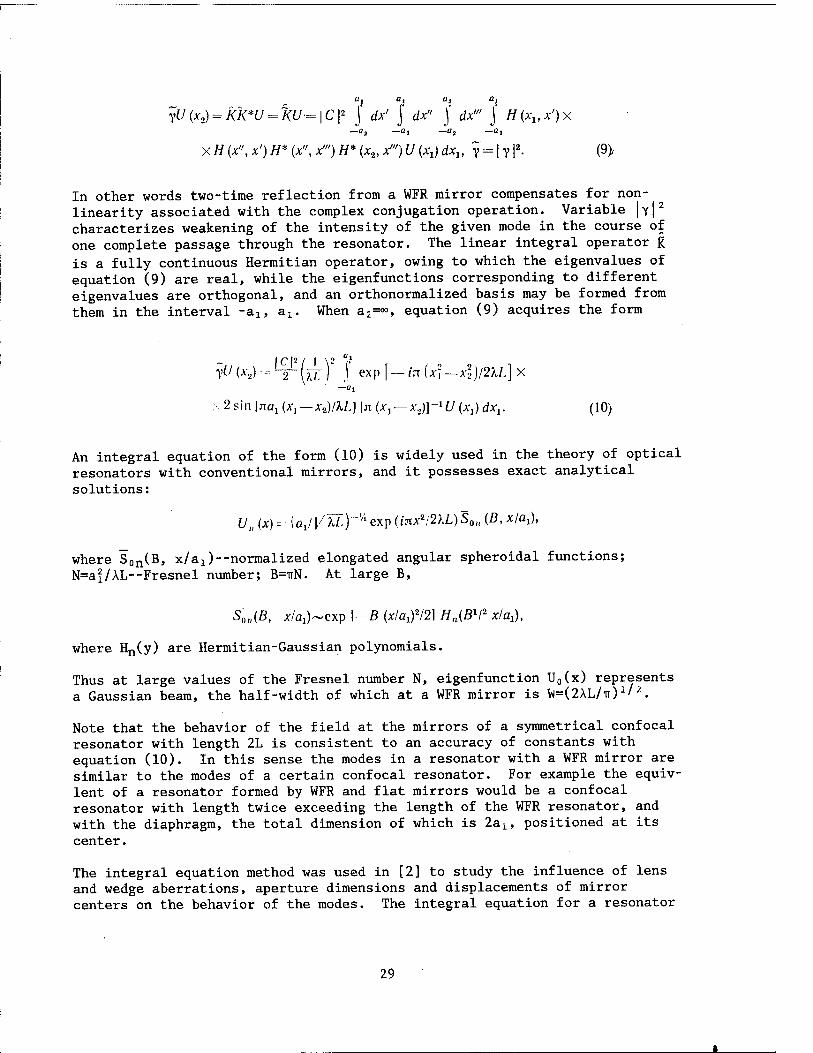
characterizes weakening of the intensity of the given mode in the course of one complete passage through the resonator. The linear integral operator K is a fully continuous Hermitian operator, owing to which the eigenvalues of equation (9) are real, while the eigenfunctions corresponding to different eigenvalues are orthogonal, and an orthonormalized basis may be formed from them in the interval -alt ax. When a2=°°, equation (9) acquires the form
yU (A-,) •--: '"IT (AT)* j' exP f — '" (x*—xl)/2\L] X -0,
\ 2 sin IJTöJ (A-, — x2)/KL] \n (A-, —A',)]-1 U (A,) dxv (10)
An integral equation of the form (10) is widely used in the theory of optical resonators with conventional mirrors, and it possesses exact analytical solutions:
U„ (x) - [aj |/XZ)-Vi exp (inx*:2KL) S0„ (B, x/aj,
where Son(B, x/a^—normalized elongated angular spheroidal functions; N=af/AL--Fresnel number; B=TTN. At large B,
S0„(B, A-/fl])~exp I—ß (xlaifl2\ //„(ß1/2 x/aj,
where Hn(y) are Hermitian-Gaussian polynomials.
Thus at large values of the Fresnel number N, eigenfunction U0(x) represents a Gaussian beam, the half-width of which at a WFR mirror is W=(2AL/TT)1'2.
Note that the behavior of the field at the mirrors of a symmetrical confocal resonator with length 2L is consistent to an accuracy of constants with equation (10). In this sense the modes in a resonator with a WFR mirror are similar to the modes of a certain confocal resonator. For example the equiv- lent of a resonator formed by WFR and flat mirrors would be a confocal resonator with length twice exceeding the length of the WFR resonator, and with the diaphragm, the total dimension of which is 2ax, positioned at its center.
The integral equation method was used in [2] to study the influence of lens and wedge aberrations, aperture dimensions and displacements of mirror centers on the behavior of the modes. The integral equation for a resonator
29

formed out of two WFR mirrors was solved in [19,20]. Methods of designing conventional resonators equivalent to resonators made from a WFR mirror and a concave or a convex mirror are described in [19].
2.3. Transverse Mode Structure in a Resonator with a Self-Pumping WFR Mirror
Let us examine the behavior of modes in a resonator with a self-pumping WFR mirror (SWFR mirror, see Figure 2). It will be demonstrated below (see also [21]) that presence of nonzero curvature of the wavefront of reference waves elicits phase modulation of the reversed wave, and under certain conditions it leads to the appearance of modes in the resonator typical of an unstable resonator. This behavior makes possible good selection of modes with respect to losses, which leads to rapid establishment of stable lasing conditions. This is very important to laser systems in which a high gain is required, as is true with a wavefront reversal system. Therefore we will assume that in order to permit control of the curvature of the wavefront of the reference waves, a lens with focal length f is positioned before the WFR mirror in the feedback arm. As a result of four-wave mixing, field Ux(x) striking the WFR mirror is transformed into UOTP=U2(X)U*(X) upon reflection from it, where U(x) is the complex spatial amplitude of the reference wave. We will assume that the exit mirror has unlimited transverse dimensions and that a limiting diaphragm is positioned in front of the WFR mirror. This diaphragm will be described as a Gaussian spatial filter with effective dimension a.
Considering all of the remarks made above, the integral equation used to determine the modes in a resonator with an SWFR mirror would have the form
A'2 \
yU[x3):- j U\ (A-,,) [ku{x]))2exp[~i4fx'-'^) x
where 1/,(A-8)--- f..{/(Jtjjexp^ — i5771A'i~x*\2)dxi and Mx^, U(x)—the field at — 00
the WFR and exit mirrors respectively; K--operator describing transformation of the field upon passage of the reference wave along the optical path between the WFR and exit mirrors; KU(x)--amplitude-phase distribution of the reference wave at the WFR mirror; L^-resonator length.
Before going on to solving integral equation (11), we need to point out some of its typical features. We can immediately note that integral equation (11), which describes the behavior of oscillations in a resonator with an SWFR mirror, belongs to a completely new class of integral equations, ones which had not been encountered previously in research on conventional resonators and on WFR resonators with an external pumping source [2-6]. Integral equation (11) is significantly more nonlinear than the equation for the modes of a resonator with a WFR mirror pumped by an external source, and what is
30

most important, it cannot be reduced to a linear equation, as in the latter case This fact is the product of the circumstance that the complex co- efficient of reflection of a WFR mirror is determined by the square of the amplitude-phase distribution of the beam subject to reversal itself.
Note also that inasmuch as equation (11) is nonlinear, modes are defined as self-repeating solutions, and they are no longer a complete system of ortho- gonal functions in relation to which any solution to the equation breaks down, Is in the case for example with linear integral equations. Diffraction losses of the resonator under consideration here also do not correspond to the commonly accepted definition of this concept. In fact, the coefficient of reflection of a WFR mirror is a function of intensity, and therefore losses would depend not only on the form of the fundamental solution.
To calculate the field in a resonator with a self-pumping WFR mirror, we need to know the form of operator K in (11). Without loss of generality, we can assume for the preliminary analysis that K is a fundamental operator Unis situation occurs when the optical system in the feedback arm creates an unmagnified image of the exit mirror at the WFR mirror). Exact solutions to integral equation (11) are unknown in analytical form even in relation to such a simple operator K. However, it may be assumed that there exists a solution in the form of a Gaussian beam U(x)=exp(-ax2+ißx2). Substituting a solution of this form into integral equation (11), we get a system of third- order algebraic equations, from which we can determine the Gaussian beam parameters a and ß:
(a2+$2)(A +2a)—B2A +2BCa—2ß2a—4paß=0, (a2+ß2)(C—2ß)—B2C—4Ba2+2BAa=0, (12)
where A = \/a2; B=kl2Li, C=k/2f; fe—wave number.
The order of this equation system may be decreased in the case of a very wide WFR mirror. Ignoring terms containing A, we find the solution to equation system (12):
p,-(2ß Cf:2{2C- 5B), a \2\iB\I^BC-frVi~ (13)
and a=0, which is an incidental solution inasmuch as in this case we could not ignore A in (12). Ignoring A in comparison with a means that the beam subject to reversal and having the effective dimension W=(2/a) ' acts as the diaphragm at the WFR mirror.
Varying the curvature of the wavefront of the reference waves by adjusting the focal length f of the lens, as in the case of a resonator with a WFR mirror having an external pumping source [24], we can control the modal volume. In fact, it follows from (13) that as the optical strength of the lens increases (as f decreases), the dimension of the beam at the exit mirror increases (o*0). However, this increase cannot occur without limit, inasmuch as given comparable dimensions of the diaphragm and the beam at the exit mirror, we need to account for diffraction at the diaphragm (we cannot ignore A).
31

To describe the behavior of modes in the case where the dimensions of the beam at the exit mirror are large (a-K)), we can use the method of successive approximations, representing ß in the form ß=ß0+e, where ß0 is the zero approximation and e is a small correction factor. Considering that condition a<A is satisfied when OB, we get ß0=±B from (12) as the zero approximation. Then equation system (12) takes the form
(a2+e2+ß2±2eß)(,4+2a)—B2A+2BCa— 2B2a+4aB(z—B) 0; (a»+e»-f B2 ± 2eB)(C+2E—2B)—B2C—'iBa2—2BA a ■--- 0. (14)
Leaving in this equation system those terms that are not larger than the first order of smallness with respect to e and a and solving the resulting system, we find
B=B*/C; a-=eA/C=±BiA/C*=±(f/L)*A. (15)
Because a must be positive, ß0=-B is a positive root. Note that at very large
C(f-»0) the dimension of the beam W=(2/a)1'2 in a resonator with a WFR mirror with external pumping exhibits the same dependence on f as does (15).
Let us find the highest modes as the self-reproducing solution to (11) in the form
Un(x)=-A„(x)exp(—aut*+i$x*), (16)
where An(x) is an n-th degree polynomial, n=0,l,2....
Let us simplify the form of function U2(x) in (11) by considering only the diaphragm factor (the exponential term) and ignoring amplitude modulation (assuming A£(x)=const) contributed by reference waves. Given this approxima- tion of U2(x), equation (11) is similar in its properties to the equation for a resonator with a WFR mirror with an external_pumping source, and a non- zero solution in the form of (16) with An(x)=Hn(x/a), where Hn(y) are Hermitian polynomials, is permitted.
When the exact function U2(x) is substituted in the right side of (11), following integration we get the function
A3n(x)exp( — qx 2)~ \2Hsi(i- L/=i
Bpx) bj exp (—ax- -j- ißx2), (17)
where p=[2a—2iß+tC+,4+ß2/(a+/ß—iB)]-1/2.
Considering that the exponential term in (17) "cuts" function Hj(y) when x/a<l, at large a (when |pB|«l) the right sides of integral equation (11) coincide approximately when the approximate and exact functions U2(xJ are substituted in it, and the solution to (11) may be given in the form (16).
32

The perturbation method can be used to obtain an exact expression for the self-reproducing solution to (11).
In concluding this section, we will consider the question of the eigenfrequencies of a resonator with an SWFR mirror. Let the wave phase at the exit mirror be equal to <|>c. The wave phase in the case of a single passage through the resonator from the exit mirror to the SWFR mirror equals qy ^Lj+^i+^V where $x is the phase depending on transverse structure of the beam. When reflection occurs from the SWFR mirror, the phase becomes equal to <p0T=—q>„+q>rf-<fe . where ^ is the phase of the reference waves, in which case ifi&<h==<Pc+kL*' The total phase run-on in one passage is determined by the expression qv-qv+^i+^i^qv For self-reproduction of the field to occur, the resultant phase must be equal to the initial phase $c with an accuracy within a whole number 2 IT, from which we get
2nmtt2kL2. (18)
where L2 is the distance traveled by the reference wave along the feedback circuit from the exit mirror to the SWFR mirror. It follows from (18) that the spectrum of eigenfrequencies of this resonator is the same as for a conventional resonator with length L2, which makes resonators with an SWFR mirror significantly different from resonators with a WFR mirror with an external pumping source.
2.4. Effect of Different Kinds of Distortions Contributed by a WFR Mirror on the Behavior of Modes in a Resonator. The Matrix Method of Calculating Mode Structure
It was established [2,14.22] in an examination of a resonator with a WFR mirror having limited transverse dimensions that amplitude distortions associated with the finite dimensions of the WFR mirror are the cause of appearance of nonconfluent modes. The modes in such a resonator are similar in their properties to modes typical of a confocal, generally asymmetrical, resonator.
The problem of finding the modes of ring resonators with WFR mirrors was examined in [23], and it was demonstrated that it reduces to the problem of finding the modes of a certain equivalent resonator with conventional mirrors. Following the commonly accepted practice, equivalence of two resonators is defined as equivalence of the integral equations describing the modes in these resonators. In the case where a wave propagating from the second mirror to the first passes through the resonator not in the reverse direction (see [23] and Figure 12 below), a ring resonator with WFR mirrors may be unstable (the transverse dimensions of the beam in an unstable resonator increase with each pass; however, this expansion is limited by the finite dimensions of the mirrors). Thus a resonator with an FWM mirror in which the frequency of the wave subject to reversal is not consistent with the frequency of the reference waves was studied in [8]. If the frequency of a Gaussian beam striking an FWM mirror is w+6 and the frequency of the
33

reference waves is u), then the frequency of the reversed beam becomes equal to (JJ-6, and the radius of curvature of the wavefront increases by a factor of (1-6/U))/(1+6/OJ). In this case the reflected beam, which has a frequency different from that of the incident beam, propagates in accordance with other laws of diffraction. Owing to this, modes typical of an unstable resonator appear.
It is significant that in all of the cases examined here, partial wavefront reversal of light associated with introduction of distortions of varying nature into the fields within the resonator by WFR mirrors is the cause of appearance of nonconfluent modes; in the absence of distortions, modes do not appear in the commonly accepted usage of this concept.
In the general case we also need to take account of the possibility of phase distortions introduced by a WFR mirror. As an example in the case of WFR light, in FWM conditions phase distortions may be caused by nonzero curvature of the fronts of the pumping waves.
Thus various factors responsible for partial wavefront reversal affect forma- tion of modes in a resonator with a WFR mirror differently. At the same time in real resonators, as a rule the revealed factors may be present simultaneous- ly. In this connection the need arises for studying the joint influence of different kinds of distortions contributed by a WFR mirror to formation of resonator modes. This sort of research is conducted in its entirety in [24] in relation to a laser with external pumping of a WFR mirror, encountered most frequently in experiments (see Figure 1). Here we will describe the general approach and examine two particular cases in greater detail.
We will assume that the WFR mirror under consideration here works as an ideal mirror with an effective lens with focal length f positioned right next to it. This lens affects only the reversed and not the incident wave. In reality such phase modulation of the reversed beam is attained if the reference waves are spherical and if their curvature differs. We will also assume that the WFR mirror also contributes amplitude distortions which can be described conveniently in the form of a Gaussian spatial filter with transverse dimension Wa. This simplified scheme contains all of the charac- teristics inherent to resonators with WFR mirrors effecting partial wavefront reversal, and it permits us to reveal the behavioral features of modes in such resonators.
To determine the structure of fields in a resonator with a WFR mirror we can use integral relationships similar to (8)-(10); however, the results are most comprehensible when the matrix approach is employed [8,25]. In this approach, transformation of a geometric-optic ray by an optical system is examined in the paraxial approximation. The ray may be characterized by two transverse vectors—distance from axis r=(x,y), and slope in relation to axis 9=(9x,0y). In the paraxial approximation, propagation of a ray over distance L along the axis of the resonator corresponds to the transformation r2=r1+L01, 92=6i. This may be represented in the form of multiplication of vector (r, 6) by the matrix:
34

M _ e2j-
A B' C D
.el. •- 7Y =
A B' C D =
1 V 0 1
Refraction in a thin convergent lens with focal length f may also be described
in matrix form, in which case we have
\A B~\ \ l °1 c D_ .-!// 1.1
It is noteworthy that for elements with a parabolic profile to which this approach is applicable, examination of the geometric-optic problem allows
us to provide an exact description of diffraction.
The basic mode of a resonator exp(-ikr[/2q) is characterized by the complex radius of curvature q, which is subordinated to distribution laws contained in the matrix relationships, and which is determined by the equation l/q= =l/R-iA/irW2, where R is the radius of curvature of the wavefront, W is the
dimension of the beam and X is wavelength.
Let us select the reference plane near a flat mirror and follow a Gaussian beam as it propagates to the WFR mirror and back. In this case passage of the beam through several optical elements and gaps between them is described by the product of the corresponding matrixes in the appropriate sequence T=TnTn+1...TzTx. Using formal matrix language, we can represent the action of our WFR mirror as a matrix T0ß$ equal to the product of four matrixes:
ou$
1 01 n o I r l on ■ l
0 — 1 ,+6/co 1 — 6/co
-i// i »7.
0" (19)
The first matrix on the left in this product describes ideal reversal [2] corresponding to reversal of the trajectory of the rays, while the second describes distortions caused by presence of a frequency shift 6 between pumping waves with frequency w and the wave striking the WFR mirror [8]. The third and fourth matrixes correspondingly describe the phase (lens) and amplitude (Gaussian spatial filter) distortions contributed by the WFR mirror.
Parameter q at the exit from the WFR mirror is associated with the entrance
parameter by the relationship
<7m.ix ' omj^B (20)
where the action of operator $QB$» which corresponds to matrix T0ß$ with elements A,B,C,D, on parameter q|x involves fulfillment of the operation
T0B$q=(Aq|x+B)/(Cq|x+D)-
35

Note that TQB$ and qgx are conjugated in the case of reflection from a WFR mirror, in distinction from the situation with conventional mirrors, where the parameters of input radiation are not conjugated. Return propagation of the beam through free space is described by matrix TL.
To determine the modes (eigenvalues q), we need to require that the complex radius of curvature of the Gaussian beam self-reproduces after one complete passage. This condition may be written in the form
q=f*q*, (21) where
T=TLT0^TL. (22)
However, it would be simpler to find eigenvalues q by writing the self- congruent equation for two complete passages. In this case we must keep in mind that to determine the matrix describing two passages, we cannot simply take the square of the matrix for one complete passage (as in the case of matrixes with real elements). And because after each reflection from the WFR mirror wavefront reversal occurs, the equation for two complete passages assumes the form
q^t'fq^iAtg+BtyiCtf+Di). (23)
Solving this equation relative to 1/q, we get
1 Z>,— A q — 2B3
± Dt-At\* ,c. B2 )
(24)
Substituting (22), (23) into (24), we can determine the characteristic para- meters of resonator modes in all cases of interest to us.
As an example we will examine how phase distortions contributed by a WFR mirror with limited transverse dimensions affect the parameters of resonator modes. Limitation of the aperture of the WFR mirror leads to the existence of modes typical of stable resonators [2,4,14], while phase distortions, as it would be easy to show, tend to shift the resonator into its unstable range. To reveal the joint influence of these factors, substituting 6=0 in (19), we get the following expressions from (24) for the curvature of the wavefront and the dimension of the spot of the Gaussian beam on a flat mirror:
I _ - .v (A-2 -i- fr2)± \(x* + fe2)2 + (x* + fe2))'/g (*2 + 6!i) (25) R L\(x*-\ fc2)2-j-62] '
W* = Wl — (*2 + *2)2 + *2. rr-. (26)
where ^-(U/n)1'2; x=Llf=L%JWa\ b=- k Lin Wl - 0aL/n Wa; 0,.= WJf —geometric divergence caused by phase distortions; Qn~k/Wa --divergence of the beam
36
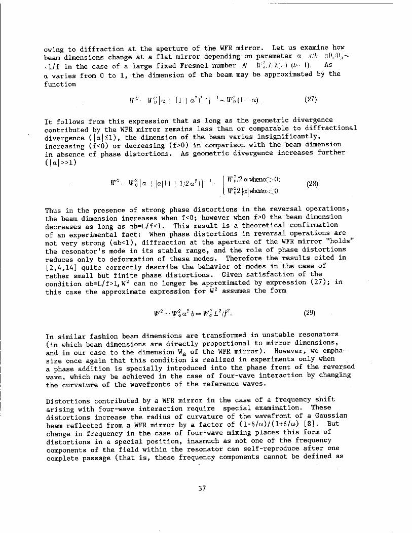
owing to diffraction at the aperture of the WFR mirror. Let us examine how beam dimensions change at a flat mirror depending on parameter a s'h n(),.''0;i~ ~l/f in the case of a large fixed Fresnel number A' \\"',:I. X> 1 (/>•■ 1). As a varies from 0 to 1, the dimension of the beam may be approximated by the function
IF- lV'|;|a | (1| a')' '| '~W'ö(l--a). (27)
It follows from this expression that as long as the geometric divergence contributed by the WFR mirror remains less than or comparable to diffractional divergence (|a|Sl), the dimension of the beam varies insignificantly, increasing (f<0) or decreasing (f>0) in comparison with the beam dimension in absence of phase distortions. As geometric divergence increases further
(|a|»l)
' W*- Wl\a-:r\a\(]\.]/2*')\ ': [■ ^^awhenaX); I W'h2 |a|whena<0.
Thus in the presence of strong phase distortions in the reversal operations, the beam dimension increases when f<0; however when f>0 the beam dimension decreases as long as ab=L/f<l. This result is a theoretical confirmation of an experimental fact: When phase distortions in reversal operations are not very strong (ab<l), diffraction at the aperture of the WFR mirror "holds" the resonator's mode in its stable range, and the role of phase distortions reduces only to deformation of these modes. Therefore the results cited in [2,4,14] quite correctly describe the behavior of modes in the case of rather small but finite phase distortions. Given satisfaction of the condition ctb=L/f>l, W2 can no longer be approximated by expression (27); in this case the approximate expression for W2 assumes the form
W-^-Wlo.2b^WlL2lf. (29)
In similar fashion beam dimensions are transformed in unstable resonators (in which beam dimensions are directly proportional to mirror dimensions, and in our case to the dimension Wa of the WFR mirror). However, we empha- size once again that this condition is realized in experiments only when a phase addition is specially introduced into the phase front of the reversed wave, which may be achieved in the case of four-wave interaction by changing the curvature of the wavefronts of the reference waves.
Distortions contributed by a WFR mirror in the case of a frequency shift arising with four-wave interaction require special examination. These distortions increase the radius of curvature of the wavefront of a Gaussian beam reflected from a WFR mirror by a factor of (1-6/üJ)/(1+6/ü)) [8]. But change in frequency in the case of four-wave mixing places this form of distortions in a special position, inasmuch as not one of the frequency components of the field within the resonator can self-reproduce after one complete passage (that is, these frequency components cannot be defined as
37
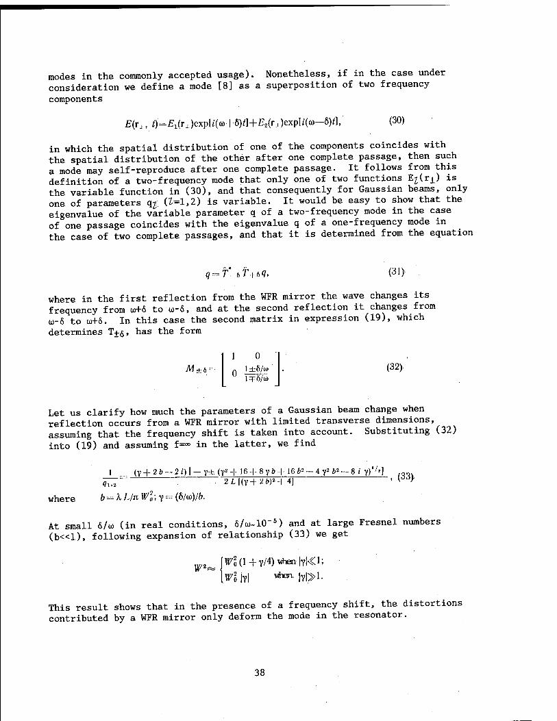
modes in the commonly accepted usage). Nonetheless, if in the case under consideration we define a mode [8] as a superposition of two frequency
components
E{rx, 0=£i('-i)exP[l'(ö)+8)0+-E2(ra)exp[i((o-6)^. (30)
in which the spatial distribution of one of the components coincides with the spatial distribution of the other after one complete passage, then such a mode may self-reproduce after one complete passage. It follows from this definition of a two-frequency mode that only one of two functions E^Uj.) is the variable function in (30), and that consequently for Gaussian beams, only one of parameters q# (£=1,2) is variable. It would be easy to show that the eigenvalue of the variable parameter q of a two-frequency mode in the case of one passage coincides with the eigenvalue q of a one-frequency mode in the case of two complete passages, and that it is determined from the equation
q = T. tT+tq, (31).
where in the first reflection from the WFR mirror the wave changes its frequency from u>+6 to u-6, and at the second reflection it changes from ü)-6 to ü)+Ö. In this case the second matrix in expression (19), which
determines T+g, has the form
M ±6 '
1 0 I ±6/w
0 1=F6/<O
(32).
Let us clarify how much the parameters of a Gaussian beam change when reflection occurs from a WFR mirror with limited transverse dimensions, assuming that the frequency shift is taken into account. Substituting (32)
into (19) and assuming f=°° in the latter, we find
1 (Y --I- 2 b — 2 i) I — y± (y2 -|- '6 + 8 y b + 1C ft2 - 4 y2 b* — 8 i y)'7']
where
9l.2
b--=\LlnWl;y~(bl<a)lb.
2L|(y-f 26)H 4] , (33>
At small 6/u (in real conditions, 6/ü)~1CT5) and at large Fresnel numbers
(b«l), following expansion of relationship (33) we get
\wi jvi "^ ivi»1-
This result shows that in the presence of a frequency shift, the distortions contributed by a WFR mirror only deform the mode in the resonator.
38

Thus amplitude distortions associated with limitation of the transverse dimensions of the WFR mirror lead in most practically utilized systems to appearance of modes typical of a stable resonator, and in this case the role of phase distortions and the frequency shift reduce to deformation of the modes. Special measures may be taken (for example skewing the phase fronts of the reference waves in the case of four-wave mixing) to control the transverse dimensions of the modes, and consequently their volume [24].
2.5. Acquisition of the Mode with the Lowest Transverse Index
If there are no limiting diaphragms in the resonator (a conventional or WFR resonator) and if the mirrors are not limited in their transverse coordinates, many modes with different transverse indices are generated, and the divergence of the generated radiation may be arbitrary. For practical purposes it would be interesting to achieve lasing in Gaussian mode with a zero transverse index consistent with the diffracted orientation of radiation. In conventional resonators there are two ways of solving this problem: using unstable resonators, where losses are large for the zero mode as well, but where they grow especially quickly at the higher transverse modes (consider- able overall amplification during a passage is required if the generation threshold is to be exceeded), and use of a stable resonator with a diaphragm which readily passes the zero mode and which contributes great losses to the higher transverse modes for which the transverse dimension of intensity localization is large (only such systems are usuable in relation to laser media with low amplification per passage). The diaphragm dimension required for this purpose Wa corresponds to the situation where the Fresnel number Wl/h Ls$, calculated by way of the effective length of the resonator L3$, must be on the order of unity. Unfortunately if the elements of the resonator contain optical heterogeneities, then the dimension of the diaphragm must be made even smaller, which reduces the Q factor and the energy recovery.
When phase (nonabsorbing) optical heterogeneities are present, a WFR mirror having sufficiently large transverse dimensions, and thus one which reverses all radiation striking it, operates just as ideally as in the case where heterogeneities are absent. In other words from the standpoint of the transverse structure of the fields, a WFR mirror and a heterogeneous medium may be substituted by just the WFR mirror.
Considering the above, we can examine a resonator similar to that shown in Figure 1. In this case we assume that the exit mirror has a radius of curva- ture R0 and that there are no optical heterogeneities in the gap between the diaphragm and this mirror. Moreover we will limit our examination to modes with frequency u=u0--that is, modes with longitudinal index n=0. The deriva- tions related to two-frequency modes--that is, for modes with n^0--are similar.
If as the reference plane we adopt a plane close to the exit mirror and calculate at this mirror the component of the field emerging from the resonator, then the operation of complete passage through the resonator may be described as
39

T-- 1 L
0 1
1 0
nW:
1
0 i A
n w;
1 /,'
0 1
l—2imL(\—2L/R0) —2imL* 2//?0 —2/m(l—2L//?0) 1— 2ifflL
1 0
(34)
Here R0--radius of curvature of the exit mirror; Wa--transverse dimension of the Gaussian diaphragm; m=2/kW2. Equating curvature q after a complete passage to the initial curvature, we get the equation q=(Aq*+B)/(Cq*+D), where A,B,C, D are elements of matrix T in (34). We write the expression for the real radius of curvature R of the wavefront of the mode and the expression for the constriction of mode W at the exit mirror:
R=L a + W = (l-<z)|l-q|
N = 1/2 m L=nWl/2 X L;a = L/R0.
LA(iV2 + (l-a)!!),/* jiA'jl—a|
'/= ; (35)
Let us discuss the results for the case of a flat exit mirror (R0-*0, ctM)). In this case R = LVl+Na, W = [XL VN*+ \/nN)V\ where N is the Fresnel number of the resonator. We fix the distance L from the exit mirror to the diaphragm and vary Wa or, what is the same thing, the Fresnel number N.
At small N«l--that is, at a small diaphragm radius Wa, we have R=L, W ä5 [kL VN2 + 1/nN)Vi --that is, a divergent Gaussian beam with its constriction in the vicinity of the diaphragm emerges from the resonator. Following reflection from a flat mirror, this wave approaches a diaphragm with radius of curvature R'=2L and beam dimension W'=2W. When N«l, the resonator possesses a very low Q-factor: A large part of the beam is cut off by the diaphragm, inasmuch as W'»Wa. For lower modes the proportion of energy passing through the diaphragm in the case of complete passage through the resonator is [1+2W 2/Wa]
_1 while for Nil this proportion equals ~N2/A«1. Losses would be even greater for Hermitian-Gaussian modes with transverse indices s, p; the dimension of their localization on the diaphragm is on the order of W^p~W' (s+p+1)
1/2 .
In the case of a large Fresnel number, N>>1, we have R=LN=irWa/2X, W=(AL/ir)1'2.
In this case the lowest mode corresponds to a Gaussian beam with an almost flat wavefront, and the structure of the beam is practically identical throughout its entire volume from the diaphragm to the exit mirror. In this case the losses are not large: For a Hermitian-Gaussian mode with indices s, p, the proportion of energy passing through the diaphragm in the case of a complete passage equals
l—2(s + p+l)LX/nWl = l — (s + p + l)IN. (36)
40

Unfortunately when N»l selection of the highest transverse modes weakens.
The structure of the modes, their Q-factor and selection are approximately the same in relation to different N for a resonator with a diaphragm and a WFR mirror, examined above, and for resonators with conventional mirrors and diaphragms at the same N but with the significant condition that there are no optical heterogeneities in the conventional resonator. One merit of a resonator with a WFR mirror is insensitivity to that part of phase hetero- geneities which lies between the selecting diaphragm and the WFR mirror. In the case Ns2-3 and when the threshold is not exceeded too greatly, the highest transverse modes do not participate in lasing in either conventional or WFR resonators. In this case the zero mode in a conventional resonator is highly distorted; moreover the Q-factor may be low due to loss, at the diaphragm, of rays deflected by heterogeneities. In contrast to this, in a WFR resonator at the same N the lowest mode has a diffracted quality and a good Q-factor even when optical heterogeneities are present. Therefore a diaphragm of significantly greater dimensions may be used in a WFR resonator generating the lowest mode, while simultaneously moving this diaphragm away from the exit mirror in order to preserve the Fresnel number N. This produces a payoff both in the divergence of the generated radiation and in the effectiveness of energy pick-off from the entire volume of the working medium.
2.6. Statistics of Fields in Lasers with a Randomly Heterogeneous Medium
Resonators with WFR mirrors are of interest owing to their capacity for compensating for aberrations within the resonator, which fluctuate in space and in time. The random nature of these fluctuations is responsible for the irregularity of the experimentally recorded fields of radiation emerging from a laser. If we are to describe internal resonator fields quantitatively, we need to know their statistics—ones such as the mean and the correlation function [26-30].
Let us examine a resonator formed out of a boundless flat mirror and a WFR mirror. Heterogeneities in the index of refraction of the medium can be represented in the form of a thin phase screen positioned near the flat exit mirror. This position of the phase screen is interesting in that hetero- geneities of the medium would have a maximum influence upon the form of the fields formed by the resonator in this case [1]. Using a standard procedure we can obtain an integral equation describing the distribution of the field U(t) at the exit mirror:
yU (p) = j f U* (t) K{r)H\ (r, t) H i (p, r) T*(l) T (p) dtdr, (37).
where '//j (r,/)=exp [—ik (r— t)-/2L] ""free space transfer function; T(p)= exp[iS(p)J--phase screen's transmission function; S(p)--random phase run-on acquired by a regular wavefront passing through the screen; K(r)--coefficient
41

of reflection of a WFR mirror. Integral equation (37) was obtained for a concrete realization of heterogeneities in the medium's index of refraction. In the general case, the form of each individual realization is unknown (or it is known with an accuracy to random parameters) and, moreover, it is random. Therefore in this situation we can consider only the mean values.
In order to obtain an expression for the mean field, we need to solve the integral equation describing the behavior of modes in the resonator in relation to a concrete realization of the medium's index of refraction. Then we need to average the resulting expression in relation to all possible realizations. However, this approach is possible when the concrete form of heterogeneities in the medium's index of refraction is known with an accuracy to a small number of random parameters, and if integral equation (37) can be solved in relation to this form of heterogeneities. This method was used in [29] to determine fields in a resonator with a randomly heterogeneous medium taking the form of a lens and a wedge. At large Fresnel numbers the basic mode of a resonator with a WFR mirror in relation to wedge hetero- geneities (S(p)=6kp, where p is the wedge angle) has the form [29] (K(r)= =exp (-r2/a2))
('((') iwp I (it-XL ! 2/ <r)(j• ft/.)2l. W> :
It is evident from (38) that a wedge optical heterogeneity does not have an influence on the dimension of the beam or on the radius of curvature of the wavefront of the radiation; however, the center of the beam at the exit mirror is determined by the wedge angle, and it is shifted relative to the position of the beams in the absence of heterogeneities by an amount 6L.
Assuming that the wedge angle 6 is random, that it has a normal distribution and that its variance is a2,
P(6) (l/y'2na)*xf>{ 6s/2oB),
and averaging (38) in relation to all possible angles 6 in accordance with
the formula <t/(,,)>„ ' (U ((>, 6) P(6),/6, we *et an expression for the mean field
oo
in the plane of the exit mirror:
<(/ ((»)>„- exp {—(n/XL -| ■ 2i/a") (>"} >; X cxp{|(n,7./. ! 2(/a2)(./.|2/|l/o- \-nL/l \-2iL-/a"\). (39)
The mean mode <U(p)>«$ is formed by all possible modes (38), which occupy positions on the exit mirror corresponding to the optical power of the wedge. Averaging results in redistribution of energy associated with each mode in accordance with a normal distribution, and thus the area occupied by the mean mode (39) is proportional to the sum of the areas of the individual modes
(38).
42
Let us consider the fact that such a meticulous examination of the influence of wedge aberrations on the behavior of fields in a resonator with a WFR mirror is not only of academic interest. Heterogeneities in the index of refraction of a rather wide class of active media that are actually encountered in experiments may be represented in the form of wedge heterogeneities. Thus a random wedge heterogeneity may be approximated by any randomly heterogeneous medium which causes mild diffractional spreading of a light beam as it passes through. In this context the condition of "mild" diffractional scattering means that as it passes forward and back through the resonator, the light ray remains within the limits of the same heterogeneities of the medium's index of refraction (the width of the angular spectrum of the light field scattered by a randomly heterogeneous medium does not exceed the radius of correlation of phase heterogeneities). Under such propagation conditions, when we expand the realization of phase S(t) in the vicinity of point p into a Taylor series, we can limit ourselves to the first two terms:
S(fl«S (p)+S'(p) :(f-p).
Then phase run-on for a complete passage S(p)-S(t)=-S'(p)(t-p) is consistent with the expression for a wedge for which 6=S'(p). In this case we should keep in mind that S and S' are random functions, and that the distribution law of the derivative S' is determined by the distribution law of S. It is known [31] in regard to a normal random process S(p) with correlation function R(x) that its derivative 8S(p)/3p is also a normal random process with correlation function R1(x)=-R"(x) (variance a|=-R"(0)). Substituting a\ in (39), we get an expression for the mean field in a resonator with a WFR mirror in the case of mild diffractional spreading of the beam.
The approach examined earlier is applicable only to special forms of hetero- geneity in the medium's index of refraction for which we can solve the integral equation (37). In all other cases we need to resort to statistical methods of obtaining closed (exact or approximate) equations for the moments of random fields. Statistical methods are unique in that they allow us to calculate average values pertaining to an ensemble of realizations.
Averaging (37), we get an integral equation for the mean field in the form
<Y> <U(f>)>= j j K{r)H\(r,i)Hx(p,r)(T*{i)T(v)U*{iy>drdt. (40) -CO —00
For each concrete realization of the phase screen, the form of the resonator's mode is functionally dependent upon the form of the phase profile of the screen, and therefore in the general case the field that establishes in the resonator is not statistically independent of fluctuations contributed with each passage by the phase screen--that is, correlation of functions U*(t) and T*(t)T(p) must be accounted for in (40).
43
Equation (40) was solved in [29] without regard for the correlation between U*(t) and T*(t)T(p). The correlation may be ignored only in the case of intense diffractional beam spreading, where rays traveling on the return pass shif^ in the transverse direction by an amount exceeding the radius of corre- lation of the screen's phase heterogeneities. It is clear, however, that in this case compensation of phase distortions does not occur.
The solution to equation (40), which does not account for correlation of the field and the transmission function of the phase screen, may be represented
in the form <f/(p)>=exp[-ap2/(l+a2/ß2)V2+tap
2/(l+ß2/ai!))>/2,
where a=k/2L; B=kW/4L*+q; /C(r)-exp(-r2/a2); <7=/?(0)£2//2 --for a randomly heterogeneous medium with correlation radius I and phase correlation function #(Pl-p2)=exp[-(Pi-p2)
2//2]A(0) , and q=a2k2/2 for a random wedge.
It is evident from the last relationships that a solution obtained without accounting for the correlation of the field and the transmission function of the phase screen can differ strongly from an exact expression for a mean field (compare with the exact solution of (39) for a random wedge). This approach can be used to obtain expressions for the correlation function of the field <U(pi)U*(p2)> similar to expressions for a mean field.
Dayson's method [31], employed in quantum electrodynamics and in the theory of multiple wave scattering, should be used to derive a closed integral equation for a mean field (and the correlation function of the field) account- ing for the field correlation and the transmission function of the phase
screen.
Integral equation (37) for expressing the field in operator form appears as
follows:
where K is an integral operator (see (9) and (37)). Let us represent the exact values of the field and integral operator K in the form of the sum of the mean and the fluctuating part:
U=V+D, K=R+1(, where the bar and the wavy line indicate the average for the^ensemble of realizations and the fluctuating part. Substituting U=U+U, K=/f+/C xnto
integral equation (37) in operator form and averaging the latrer, after some pie transformations we arrive at an equation for the mean field sim
ü=~ku*+Rü* (41>
and field fluctuations (subtracting (41) from operator equation (37))
Ü=kV*+KU*+KU*—KÜ*. . (42>
44

In the case where Ki/*=j^O, it follows from (41) that the equation for the mean field does not coincide with the equation for individual realizations of this field (37). As was noted above, this situation occurs in the case of mild diffractional beam spreading, where the correlation between the field and the transmission function of the phase screen is significant. Equation (42) for field fluctuations is nonlinear relative to Ü and R. We will use the iteration method to express field fluctuations Ü in explicit form. As our first approximation iK1' we will use the term in (42) not containing Ü: JJO)-JKD*.
Continuing the iteration process--that is, successively suDstituting fKn_1' in the right side of equation (42), we will obtain n-th order approximations for field fluctuations. Next, substituting this approximation U^n) for field fluctuations in equation (41), we get a closed equation for the mean field U^nJ, which as an example has the following form in the first-order approxi- mation:
At first glance the last equation does not appear better in any way than equation (37) in operator form; it even looks more complex. But this is not so, inasmuch as the equation for UA1' contains averaged smooth operators, in distinction from equation (37), operator K of which includes rapidly oscil- lating functions.
A detailed examination of the behavior of the mean field and its correlation function in resonators with a randomly heterogeneous medium using Dayson's method will be published in the near future.
2.7. Numerical Results of Modeling Lasers with WFR Mirrors
As we saw in the previous sections, the values of aberrations that may be corrected are limited by the transverse dimensions of the WFR mirror and the exit mirror. In the case where the transverse dimensions of these mirrors are large, and namely when
Nn - WlvllL, N0B<t, = WU/XL > 1,
the fundamental modes in a laser with a WFR mirror are represented by Gaussian- Hermitian beams. But if the dimensions of the mirrors become comparable with the dimensions of the beams at these mirrors, then owing to diffraction effects the Gaussian beam approximation ceases to be valid. Characteristic solutions at small Fresnel numbers may be determined by numerical methods, ones such as the well known (Foks-Li) and (Proni) methods.
Transverse modes in a laser with a limited WFR mirror were subjected to numerical calculation in [22] using a fast Fourier transformation. A resonator with length 2L consisting of a boundless flat mirror, a diaphragm
45

with width 2a positioned a distance L from a conventional mirror, and a WFR mirror with width 2b was examined in this work. The table gives the eigen- values for WFR and conventional resonators.
(1) (2)
Nn~ay}.L b/a sf
*i o P-x
G to O
1,875 1,875 0,300
1,2 4,0
10,0
0,849 0,835 0,260
0,990 0,999 0,530
Key: Conventional 2. WFR
Figure 3. Dependence of Attenuation of Mode Intensity \y\ in One Passage (a) and (Strel's) Number S (b) on the Amplitude of the Phase Grating $0 for WFR (1) and Conventional (2) Resonators
This work also analyzed the influence of phase distortions inside the resonator on mode behavior. The fundamental mode in a resonator with a phase grating positioned flush with the diaphragm and separated from the conventional and WFR mirrors by a distance L was determined numerically. The grating had a phase distribution Afl>(*)=A<J>0cos(2it*/r). Figure 3 shows the eigenvalues and Strel's number, which is equal to the ratio of intensi- ties of exit radiation in the presence of a phase screen and without it, depending on phase dispersion A$0 when 2a/T=10, Na=1.875 and b/a=4. As would have been expected, when a phase grating is present the diffraction losses, which are equal to 1-|Y|2, assume smaller values while Strel s number assumes larger values for a resonator with a WFR mirror than for a resonator with conventional mirrors.
An internal resonator adaptive system was subjected to numerical modeling
in [32].
46
2.8. Steady-State Energy Characteristics of SWFR Mirror Lasers
Use of WFR mirrors in lasers has a number of specific characteristics associated with the nonlinear dependence of the coefficient of reflection on the intensity of the reference waves. Under certain conditions this dependence may lead to the existence of numerous energetic steady states of exit radiation [11,33].
We will analyze amplification of crossing waves in the active medium of a laser (see Figure 2) on the basis of a two-level concentrated model of the active medium. Within the framework of this model, in the steady-state case, when the duration of the laser pulse exceeds the times of longitudinal and transverse relaxation of the medium, the amplification factor is
x-exp[G0/(l+ /)'"], (43)
where I0--intensity of the internal resonator field, normalized in relation to the intensity of saturation of the active medium; G0--unsaturated incre- ment of amplification by a weak wave; m--saturation index (m=l for a homo- geneously widened luminescence line, and m=l/2 for a heterogeneously widened luminescence line).
For the standard FWM model, the effectiveness of reflection with respect to intensity R0 of the signal wave I3 into a reversed wave is determined by the relationship
#o=tg%/on), (44)
where q--interaction constant; Ion--intensity of reference waves. Relation- ship (44) is valid in the approximation of a given field of reference waves-- that is, on the condition that I3, Ilt<<I0n-
Let 1o be the intensity of the resonator field striking the exit mirror, which has a reflection coefficient Rg (where TB=(1-Rg) is the transmission factor). The intensity of the reference waves is Ion=I0TBR3; then the intensity of the wave reflected from the WFR mirror is
U=hlg\qI»T*Rz), (45)
where R3 is the coefficient of reflection of semitransparent mirror 3 (Figure 2); h—hRj*-
Lasing occurs in the case when the losses are balanced by amplification. Ignoring diffraction losses and accounting only for losses associated with departure of radiation from the resonator, we get the threshold condition for lasing in the form
/0=/4x,
which assumes the following form after expressions (43)-(45) are substituted into it:
tg2 [qRa (1 - /?„) /„] = exp [ - 2G0/( 1 + /„)'" ] R»' • (46)
47
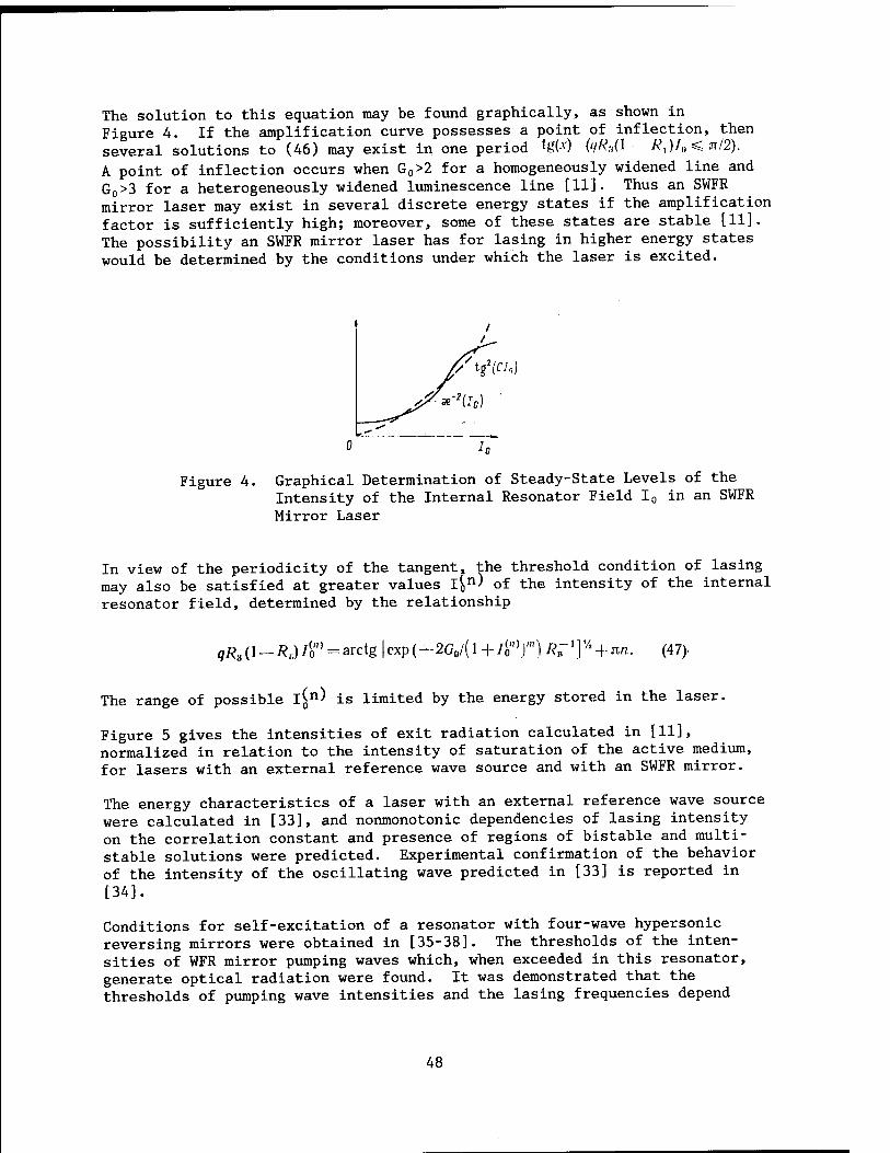
The solution to this equation may be found graphically, as shown in Figure 4. If the amplification curve possesses a point of inflection, then several solutions to (46) may exist in one period {g(-v) (<lRaO - /?,)/„< n/2). A point of inflection occurs when G0>2 for a homogeneously widened line and G0>3 for a heterogeneously widened luminescence line [11]. Thus an SWFR mirror laser may exist in several discrete energy states if the amplification factor is sufficiently high; moreover, some of these states are stable [11]. The possibility an SWFR mirror laser has for lasing in higher energy states would be determined by the conditions under which the laser is excited.
Figure 4. Graphical Determination of Steady-State Levels of the Intensity of the Internal Resonator Field I0 in an SWFR Mirror Laser
In view of the periodicity of the tangent, the threshold condition of lasing may also be satisfied at greater values l[n> of the intensity of the internal resonator field, determined by the relationship
^(^^/«"»^arctg |exp(-2G0/(l +4'°)'") R'^ + nn. (47)
The range of possible l(n) is limited by the energy stored in the laser.
Figure 5 gives the intensities of exit radiation calculated in [11], normalized in relation to the intensity of saturation of the active medium, for lasers with an external reference wave source and with an SWFR mirror.
The energy characteristics of a laser with an external reference wave source were calculated in [33], and nonmonotonic dependencies of lasing intensity on the correlation constant and presence of regions of bistable and multi- stable solutions were predicted. Experimental confirmation of the behavior of the intensity of the oscillating wave predicted in [33] is reported in [34].
Conditions for self-excitation of a resonator with four-wave hypersonic reversing mirrors were obtained in [35-38]. The thresholds of the inten- sities of WFR mirror pumping waves which, when exceeded in this resonator, generate optical radiation were found. It was demonstrated that the thresholds of pumping wave intensities and the lasing frequencies depend
48

10 20 30 f-0
Figure 5. Dependence of the Intensity of Exit Radiation on the Unsaturated Amplification Factor of the Medium in Lasers with an External Reference Wave Source (1) and with an SWFR Mirror (2) [11]
Key: 1. Relative units db
periodically on the distance between the reversing mirrors. Lasers with WFR mirrors based on ChW [not further identified] in photorefractive media are
examined in [39-41].
2.9. Effectiveness of WFR Mirror Lasers. Lasers [11]
Comparison with Conventional
WFR mirror lasers make it possible to improve the quality of the beam, but part of the energy is used to pump the WFR mirror. On the other hand radiation from a conventional laser produces a beam of poorer quality, but the output power is higher than for a similar laser with a WFR mirror. In this context the term "similar" indicates a laser with equal losses and an unsaturated amplification factor. The effectiveness of lasers with WFR and conventional mirrors may be assessed comparatively on the basis of energy concentrated in the angle determined by diffractional divergence of the beam in the case of identical energy entering the system. In the ideal case, the exit energy of a WFR mirror laser is equal to PH#, and the beam exhibits diffractional divergence. A conventional laser with optimum radiation output has maximum exit energy P0. As a rule, the exit radiation of a conventional laser experiences significant distortions; in this case the quality of the beam is determined by parameter ß, equal to the ratio between beam divergence and the diffraction angle. Let us designate by ße the quality of the beam of a conventional laser at which equal exit energies are concentrated in the diffraction angle of this laser and a WFR mirror laser:
'PJti + P*, $e=--[P0l{Pm-Px)) (48)
Relationship (48) includes the energy Px of an external pumping source (if it is present), because reference waves possess beam quality no worse than that
49
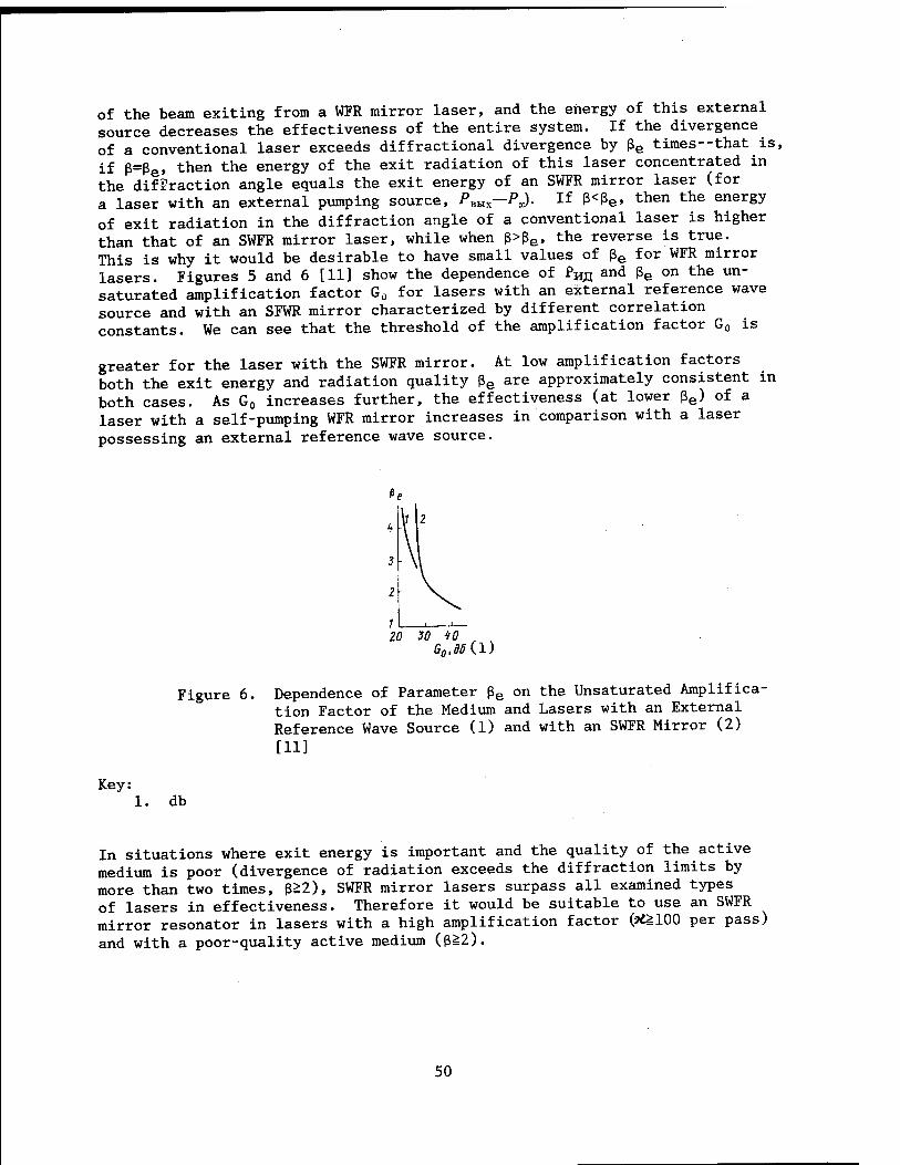
of the beam exiting from a WFR mirror laser, and the energy of this external source decreases the effectiveness of the entire system. If the divergence of a conventional laser exceeds diffractional divergence by ße times--that is, if ß=ße» then the energy of the exit radiation of this laser concentrated in the diffraction angle equals the exit energy of an SWFR mirror laser (for a laser with an external pumping source, Pam—PJ. If ß<ße» tnen the energy of exit radiation in the diffraction angle of a conventional laser is higher than that of an SWFR mirror laser, while when ß>ße, the reverse is true. This is why it would be desirable to have small values of ße for WFR mirror lasers. Figures 5 and 6 [11] show the dependence of £m and ße on the un- saturated amplification factor G0 for lasers with an external reference wave source and with an SFWR mirror characterized by different correlation constants. We can see that the threshold of the amplification factor G0 is
greater for the laser with the SWFR mirror. At low amplification factors both the exit energy and radiation quality ße are approximately consistent in both cases. As G0 increases further, the effectiveness (at lower ße) of a laser with a self-pumping WFR mirror increases in comparison with a laser possessing an external reference wave source.
20 30 40 , ^
Figure 6. Dependence of Parameter ße on the Unsaturated Amplifica- tion Factor of the Medium and Lasers with an External Reference Wave Source (1) and with an SWFR Mirror (2)
[11]
Key: db
In situations where exit energy is important and the quality of the active medium is poor (divergence of radiation exceeds the diffraction limits by more than two times, ߣ2), SWFR mirror lasers surpass all examined types of lasers in effectiveness. Therefore it would be suitable to use an SWFR mirror resonator in lasers with a high amplification factor (*£100 per pass) and with a poor-quality active medium (ßä2).
50

2.10. Experimental Results
There are now a rather large number of publications concerned with experimental research on WFR mirror lasers. A pulsed ruby laser with an FWM mirror was first achieved in [8]. As Figure 7 shows, an FWM mirror is a cell 40 cm long containing CS2, and the pumping waves were created by a second pulsed ruby laser. In order to increase the length of nonlinear interaction, the reference waves propagated parallel to the optical axis of the WFR resonator, and polarizers were used to separate the reference waves from the reversed wave. The energy of the pulse exiting from the WI-i resonator was around 1 percent of the energy of the reference waves.
h ' (w)F
Ex B 'i i tu
Figure 7. Ruby Laser with an External Reference Wave Source [8] l--mirror; 2--ruby; 3--(Glan's) prism; 4--FWM medium
Figure 8. Copper Vapor Laser with an Externally Pumped WFR Mirror [43]: l-3--mirrors; 4--copper vapor
Lasing was achieved in [42] by a flat mirror and a WFR mirror in which a BaTi03 crystal served as the nonlinear medium and an argon laser served as the pumping source. When a phase plate was introduced near the WFR mirror, the intensity of exit radiation did not weaken noticeably.
It is reported in [43] that lasing was achieved and studied in a resonator with a WFR mirror formed by four-wave mixing in a resonance-amplifying medium of Cu vapor excited in a longitudinal discharge. The active zone of the
51

discharge had a diameter of 7 mm and a length of 50 cm. Crossing pumping waves were formed by a resonator (Figure 8) consisting of flat mirrors 1 and 2. Spatial coherence of pumping waves is achieved by positioning the diaphragms. Mirror 3 was adjusted in such a way that its axis crossed the axis of the pumping beam near the opposite end of the tube. The angle between the axes was 6 mrad. The effective reflection coefficient for the WFR mirror was 10"5 in the case of a pumping beam with A=510 nm having a power density of 2.5 kW/cm2. Owing to the large amplification factor of the active medium (G0=12), such reflection was sufficient to cause lasing in the WFR mirror resonator, the power of which was comparable to the pumping power. The lasing pulse (T=5-8 nsec) was about two times shorter than the pumping pulse.
In a series of experiments conducted in [A4], a central longitudinal mode was observed, as the theory predicted, at the pumping frequency in addition to a pair of modes tuned away from the central frequency by an amount c/4L.
The possibility of using an inverse parametric relationship in relation to wavefront reversal in the presence of ChW was demonstrated in [45-50].
Lasing was achieved by SWFR mirror lasers in [45,50]. Difficulties associated with self-excitation of such systems are obvious, inasmuch as in the initial stage of achieving a positive feedback is practically absent owing to the weak intensities of the noise waves participating in four-wave mixing and their low degree of spatial-temporal coherence (the resonator is not closed in the direction of the WFR mirror). Lasing of this sort was achieved experi- mentally in [45] using a garnet laser; a saturating absorbent was used as the FWM medium.
To facilitate self-excitation, lasing was initiated in [45] between mirrors 1 and 2, as with a conventional läser (shown by the dot-dash line in Figure 9). Feedback was achieved in the WFR resonator (shown by a thin line) owing to four-wave mixing by means of reflection of a wave striking a cell containing saturating absorbent at a small angle to the optical axis of the conventional laser. Interaction between the WFR and conventional lasers was controlled by a (Pokkels) cell 5 and a polarizing splitter 6. After lasing appeared, the Pokkels cell was used to shut off mirror 2, after which lasing continued in the WFR mirror resonator.
\y
X
2
\ /
Figure 9. Laser with an SWFR Mirror and with Preliminary Initiation of Lasing [45]: 1,2—mirrors; 3--WFR medium; 4--AYG:Nd3+
rod; 5--Pokkels cell; 6--polarizing splitter
52

Figure 10. Copper Vapor Laser with an SWFR Mirror [50]: l-3--beams; 4-6--mirrors; 7--diaphragm; 8--copper vapor
The principal distinguishing feature of the SWFR mirror laser created in [50] is that self-excitation of the laser was achieved without additional devices intended to initiate lasing, as in [45]. A pulsed copper vapor laser was used in the study (X=510.6 nm, %=30 nsec, channel diameter 8 mm). FWM occurred in the laser's active medium as diagrammed in Figure 10. The co- efficients of reflection of flat mirrors 4-6 were 80, 100 and 4 percent respectively. The angle at which the beams crossed in the region of inter- action was 0.01 rad. The aperture of the beams was limited by diaphragm 7 with a diameter of 2 mm. Energy, pulse shape and the spatial structure of exit radiation in direction 1, 2 and 3 were recorded. The transverse structure of each beam consisted of a halo of superluminescent radiation and a central, more powerful core; in this case the core of beam 3 was extended somewhat in the vertical direction.
Beam divergence in the far zone, determined from the dimension of the core, was Ö-IO-1* rad for beams 1 and 2 and 3*10"3 rad for beam 3 (in the vertical direction). The peak intensity levels in the cores of beams 1, 2, 3 were 0.2, 150 and 0.5 W/cm2 respectively. When either of the branches of the resonator were cut off, the core disappeared in all beams, which was proof of formation of radiation making up the core as a result of parametric oscillation. When phase heterogeneity was introduced between mirror 6 and the active medium, the transverse structure of beam 2 underwent distortion, while that of beams 1 and 3 remained practically unchanged, which was a manifestation of the adaptive properties of a WFR mirror. The noncritical nature of this system in relation to the position of conventional mirror 4 is a distinguishing feature of this system: Owing to geometric factors, synchronization of beams registering the grating occurs automatically.
The first successful realization of a WFR mirror laser operating in free oscillation mode is reported in [51]. Incidental four-beam interaction was used to achieve wavefront reversal in this mode.
3. SBS Cell Resonators
Use of SBS cells to modulate the Q-factor of a pulsed laser has a rather long history (see for example [7]). Interest in such resonators arose anew in connection with the discovery of the phenomenon of self-reversal of a wavefront with SBS. The typical design of an SBS cell laser is shown in Figure 11 (see [52-56]). Unfortunately there is presently no quantitative theory or even an understanding of all of the
53

processes significant to the work of such a laser. Therefore we will limit ourselves to just a brief description of some experimental results.
The typical frequency shift with SBS is %6/2irc~0.1 cm"1 (this figure is
for SBS in acetone at X=l u). For a resonator with length L=2 m, the distance between modes with adjacent longitudinal indices is ÄQ^^^nc^^ = (2L)_1«2,5-lO-3 CM"
1--that is, it is approximately 40 times less. Therefore for practical purposes we can always find resonator modes with a frequency difference coinciding with %6 with an accuracy to the width of a scattering line T. Thus the absolute value of the resonator's length has little influence on the laser operating mode. However, as experiments showed, this mode is extremely sensitive to the position of the scattering region within the resonator [3]; the position of the SBS mirror is determined by the location of the focal constriction of the telescope within the VR-active medium (Figure 11).
Figure 11. Laser with a SBS cell [3]: l,2--mirrors; 3--amplifier; A--SBS cell
Different operating modes can be achieved with such a laser. First there is the free oscillation mode, where SBS is not developed at all. Next, with the resonator tuned in a particular way, different frequency components of the crossing waves already generated by the laser are phased in the region of the constriction in such a way as to effectively excite a hypersonic wave. If in addition the coefficient of reflection of mirror 2 in Figure 11 is noticeably less than unity, then given that a sufficiently effective acoustic reflecting hologram arises in the constriction, the resonator's Q-factor grows abruptly, and a gigantic pulse is generated.
The emission spectrum occurring in the presence of SBS may consist of several equidistant spectral components separated by a shift %g [7]. Moreover gradual displacement of the middle oscillation frequency into the Stokes region was observed in an experiment [4], such that in the time of one passage through the resonator the frequency shifted by an amount %g.
Low selectivity in relation to the transverse structure of radiation, which corresponds with the general properties of WFR resonators, was noted for SBS cell resonators [3,4]. In this case the generated radiation exhibited angular divergence noticeably greater than the diffraction limit. Nonethe- less, transverse (spatial) coherence of the radiation, measured by Young's method, was high; the authors of [3] associated this with the inertia of hypersound pumping.
54
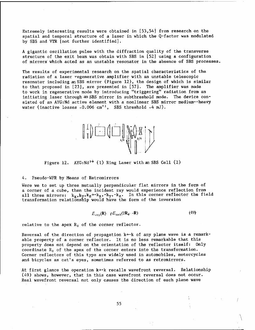
Extremely interesting results were obtained in [53,54] from research on the spatial and temporal structure of a laser in which the Q-factor was modulated by SBS and VTR [not further identified].
A gigantic oscillation pulse with the diffraction quality of the transverse structure of the exit beam was obtain with SBS in [52] using a configuration of mirrors which acted as an unstable resonator in the absence of SBS processes.
The results of experimental research on the spatial characteristics of the radiation of a laser regenerative amplifier with an unstable telescopic resonator including an SBS mirror (Figure 12), the design of which is similar to that proposed in [23], are presented in [57]. The amplifier was made to work in regenerative mode by introducing "triggering" radiation from an initiating laser through an SBS mirror in subthreshold mode. The device con- sisted of an AYG:Nd active element with a nonlinear SBS mirror medium—heavy water (inactive losses -0.006 cm"1, SBS threshold ~4 mJ).
Figure 12. AYG:Nd3+ (1) Ring Laser with an SBS Cell (2)
4. Pseudo-WFR by Means of Retromirrors
Were we to set up three mutually perpendicular flat mirrors in the form of a corner of a cube, then the incident ray would experience reflection from all three mirrors: kx,ky,kz->-kx,-ky,-kz. In this corner reflector the field transformation relationship would have the form of the inversion
£,n,,(R); ÄHAPRO-R) (49)
relative to the apex R0 of the corner reflector.
Reversal of the direction of propagation k->-k of any plane wave is a remark- able property of a corner reflector. It is no less remarkable that this property does not depend on the orientation of the reflector itself: Only coordinate R0 of the apex of the corner enters into the transformation. Corner reflectors of this type are widely used in automobiles, motorcycles and bicycles as cat's eyes, sometimes referred to as retromirrors.
At first glance the operation k->~k recalls wavefront reversal. Relationship (49) shows, however, that in this case wavefront reversal does not occur. Real wavefront reversal not only causes the direction of each plane wave
55

to reverse, but it also changes the sign of the relative difference of their phases. Contrary to this, linear operation (49) (which does not entail complex conjugation) reverses only the direction of propagation. In the language of ray optics, preservation of phase relationships corresponds to a transverse shift of an individual ray by 2a (Figure 13).
Figure 13. Path of Rays in a Corner Reflector
A spherical wave diverging from a source with coordinate R' is transformed by a corner reflector not into a wave that converges toward R', as was the case with WFR, but rather into a wave diverging from a new source with coordinates R"=2R0-R'. Thus within the limits of the aperture of the corner reflector, reversal of the central direction occurs, and not reversal of the curvature of the spherical wave beam. Let the transverse dimension D of a corner reflector be limited. Let us designate the radius of curvature of the wavefront of the incident spherical wave by r0, and let r0»D. Then deflection of the wavefront in comparison with a plane normal to the central direction of propagation is 6h~D2/r0. If 6h«A, then with an accuracy to correction factors ~(6h/A)2 (in relation to energy), within the limits of aperture D operation (49) corresponds to a WFR operation.
To raise the effectiveness of the system we often use not one corner reflector but an entire set of reflectors of smaller dimensions characterized by the set of coordinates Rlt ..., Rtf of their apexes. Then the field falling within the aperture of reflector i is transformed in accordance with relationship (49) with the corresponding R0=Ri- Owing to this, reversal of the central direction (that is, reversal of the average slope of the wave- front) occurs within the limits of each reflector, and the maximum transverse shift is limited by the dimensions of one element.
But there is a limit of suitable breakdown of individual elements. More precisely, even if we achieve WFR within the limits of each element, nonethe- less the phases of the fields reflected by the different elements exhibit relative phase shifts on the order of 2k(Ri~Rj). In the general case the wavefront of reflected radiation possesses discontinuities in the gaps between elements. Because of these discontinuities the reflected radiation acquires additional divergence 68-X/D, corresponding to diffraction at the aperture of one element.
Let us examine a two-pass system for compensating for distortions contributed by the amplifier using a set of corner reflectors [58-65] with dimension 2D
56

2D
X
Figure 14.
l~-- -L - --I
Amplifier (1) with Retromirror (2)
(Figure 14). Let a plane wave be distorted in the first pass, producing some irregular distribution 9(x) of the slope of ray 8 depending on transverse coordinate x. In the approximation of geometric optics, an individual element reverses the direction of a ray striking it with a transverse shift öOT|. (*)Ä -öi<:<;> (x '"a^ where a^D. As a result angular imprecision of compensa-
tion ööi-DdS/dx arises during the return pass through the amplifier. Finally, the wavefront of the corrected radiation consists of independent segments with dimensions ~D, which leads to additional angular distortions, <59=892. In the end, we get an estimation formula for divergence after two passes involving reflection from a retromirror:
e„cn;.- 89, + 662 + 603 = -g- DH--A- (1 -f L -£.). (50)
To evaluate the effectiveness of compensation we can compare 9Hcnp ^rom (50)
with divergence 90 obtained after one-pass amplification. In this case d9/dx~90/Z~l/R, where I is the transverse scale of heterogeneity of function 0(x); R--characteristic local radius of curvature of the distorted wavefront. The payoff in divergence is
eo/e„o„p~l£>//, +K(\ +UR)/DB0]-1. (51)
When L=0, relationship (51) is greater than unity (that is, there is a payoff)
when
M%3D,^.l.. (52)
It is not difficult to understand that the gain from using a retromirror in this system would be significant only if A/90«£j_--that is, if distortions in the amplifier are large: Local phase perturbation 6tft~k9fl£ i »1. The optimum payoff eo/6IlCnv1~V
reo/(V/:) is achieved when D~Vli\/Q0. Here is a numerical example. When 90~10"
2 rad, l±~l cm, A-10"1* cm, we have a maximum
payoff of 90/9Hcrip~10 when D~l mm. The resulting divergence is 10 times
57

greater than the diffraction limit \/lL in the case of a transverse dimension of Z-i-1 cm; nonetheless, it is 10 times better than the uncorrected divergence 60. If the dimension of elementary reflectors D is greater than optimum, then the gain worsens, being ~Z-j_/D.
In the other limiting case (less advantageous), where L»R^l, /90, we have
D~t ä V^L and the gain is ,■ e0/6HCn;i « l.,D'oPt « ]/"/" AL; this gain is
greater than unity only when L^T'.A-
We have thus far assumed that wavefront perturbations are greater than the wavelength, and we used the concepts of geometric optics. If phase distor- tions are less than or on the order of 1 rad, then the examination must be carried out by different methods. Referring the reader to the reviews [63, 64] for details, we point out here that in this case as well, use of a retro- reflector makes it possible to compensate for part of the phase distortions (and namely, the component of phase perturbation that is uneven in relation to the midpoint of the reflector).
The compensating capabilities of retromirrors were demonstrated experimen- tally in [58], in whicn divergence of a neodymium glass amplifier was improved by four times using a two-pass system. A set of retromirrors was used in [59] as one of the mirrors of a laser resonator, which made it possible to reduce divergence of a laser with an optically heterogeneous active medium by 10 times.
5. Conclusion
The basic types of WFR mirror lasers were examined above. Attention was focused on lasers with FWM mirrors, which are now enjoying the widest application. To permit practical use of FWM mirrors in laser systems, we need to solve problems concerned with formation of high quality reference waves, with effective use of energy stored in the medium, and with synchroni- zation of the reference and signal waves. In theory, the entire set of these problems can be solved in lasers with an SWFR mirror.
BIBLIOGRAPHY
1. Ananyev, Yu. A., "Opticheskiye rezonatory i problema raskhodimosti lazernogo izlucheniya" [Optical Resonators and the Problem of the Diver- gence of Laser Radiation], Moscow, Nauka, 1979.
2. Beldyugin, I. M. and Zemskov, Ye. M., in "OVF opticheskogo izlucheniya v nelineynykh sredakh" [Wavefront Reversal of Optical Radiation in Non- linear Media], Gorkiy, Izd-vo IPF AN SSSR, 1979, p 160.
3. Leshev, A. A., Semenov, P. M. and Sidorovich, V. G., in "OVF opticheskogo izlucheniya v nelineynykh sredakh," Gorkiy, Izd-vo IPF AN SSSR, 1979, p 135.
58

4. Lesnik, S. A., Reznikov, M. G., Soskin, M. S. and Khizhnyak, A. I., in "OVF opticheskogo izlucheniya v nelineynykh sredakh," Gorkiy, Izd-vo IPF AN SSSR, 1979, p 146.
5. Siegman, A. E., Belanger, P. A. and Hardy, A., in: "Optical Phase- Conjugation," New York, Academic Press, 1982.
6. Pepper, D. M., OPT. ENGNG. Vol 21, 1982, p 156.
7. Zeldovich, B. Ya., Pililetskiy, N. F. and Shkunov, V. V., "Obrashcheniye volnovogo fronta" [Wavefront Reversal], Moscow, Nauka, 1985.
8. Yeung, J., Fekete, D., Pepper, D. M. and Yariv, A, IEEE J., Vol QE-15, 1979, p 1180.
9. Reznikov, M. G. and Khizhnyak, A. I., KVANTOVAYA ELEKTRONIKA, Vol 7, 1980, p 1105.
10. Guiliano, C. R., Lind, R. C, O'Meara, T. R. and Valley, G. C., LASER FOCUS, Vol 19, No 2, 1983, p 55.
11. Karr, T. J., J. OPT. SOC. AMER., Vol 73, 1983, p 600.
12. Beldyugin, I. M. and Zemskov, Ye. M., KVANTOVAYA ELEKTRONIKA, Vol 6, 1979, p 2036.
13. Beldyugin, I. M., Galushkin, M. G. and Zemkov, Ye. M., KVANTOVAYA ELEK- TRONIKA, Vol 6, 1979, p 38.
14. Belanger, P. A., Hardy, A. and Siegman, A. E., APPL. OPTICS, Vol 19, 1980, p 602.
15. Belanger, P. A., Hardy, A. and Siegman, A. E., APPL. OPTICS, Vol 19, 1980, p 479.
16. Beldyugin, I. M. and Zemskov, Ye. M., KVANTOVAYA ELEKTRONIKA, Vol 7, 1980, p 1334.
17. Lesnik, S. A., Soskin, M. S. and Khizhnyak, A. I., ZHTF, Vol 49, 1979, p 2257.
18. Lam, J. F. and Brown, W. P., OPTICS LETTS, Vol 5, 1980, p 61.
19. Bespalov, V. I., Manishin, V. G. and Pasmanik, G. A., in "Nelineynyye volny: samoorganizatsiya" [Nonlinear Waves: Self-Organization], Moscow, Nauka, 1983.
20. Manishin, V. G. and Pasmanik, G. A., RADIOFIZIKA, Vol 24, 1981, p 986.
21. Beldyugin, I. M. and Zolotarev, M. V., KVANTOVAYA ELEKTRONIKA, Vol 12, 1985, p 682.
59

22. Hardy, A., IEEE J., Vol QE-17, 1981, p 1581.
23. Beldyugin, I. M. and Zemskov, Ye. M., KVANTOVAYA ELEKTRONIKA, Vol 9, 1932, p 817.
24. Beldyugin, I. M. and Zolotarev, M. V., KVANTOVAYA ELEKTRONIKA, Vol 11, 1984, p 591.
25. Dzherrard, A. and Berch, Dzh. M., "Vvedeniye v matrichnuyu optiku" [Introduction to Matrix Optics], Moscow, Mir, 1978.
26. Beldyugin, I. M. and Pogibelskiy, A. P., KVANTOVAYA ELEKTRONIKA, Vol 7, 1980, p 2194.
27. Lyubimov, V. V., IZV. AN SSSR. SER. FIZICH., Vol 46, 1982, p 1974.
28. Lyubimov, V. V., KVANTOVAYA ELEKTRONIKA, Vol 10, 1983, p 1897.
29. Beldyugin, I. M. and Vorotilin, S. P., KVANTOVAYA ELEKTRONIKA, Vol 11, 1984, p 1337.
30. Bolshukhin, 0. G., Orlova, I. B. and Sherstobitov, V. Ye., KVANTOVAYA ELEKTRONIKA, Vol 11, 1984, p 720.
31. Rytov, S. M., Kravtsov, Yu. A. and Tatarskiy, V. I., "Vvedeniye v statisticheskuyu radiofiziku" [Introduction to Statistical Radiophysics], Moscow, Nauka, Part 2, 1978.
32. Kovalchuk, L. V., Rodinov, A. Yu. and Sherstobitov, V. Ye., KVANTOVAYA ELEKTRONIKA, Vol 10, 1983, p 1564.
33. Odulov, S. G., Slyusarenko, S. S. and Soskin, M. S., KVANTOVAYA ELEKTRONIKA, Vol 11, 1984, p 2059.
34. Odulov, S. G., Slyusarenko, S. S. and Soskin, M. S., KVANTOVAYA ELEKTRONIKA, Vol 11, 1984, p 869.
35. Bespalov, V. I., Pasmanik, G. A. and Shilov, A. A., KVANTOVAYA ELEKTRONIKA, Vol 10, 1983, p 1352.
36. Bespalov, V. I., Kulagina, S. N., Manishin, V. G. and Pasmanik, G. A., KVANTOVAYA ELEKTRONIKA, Vol 10, 1983, p 1776.
37. Andreyev, N. F., Bespalov, V. I., Kiselev, A. M., Pasmanik, G. A., and Shilov, A. A., ZHETF, Vol 82, 1982, p 1047.
38. Bespalov, V. I. and Pasmanik, G. A., IZV. AN SSSR. SER. FIZICH., Vol 44, 1980, p 1572.
39. White, J. 0., Cronin-Golomb, W., Fisher, B. and Yariv, A., APPL. PHYS. LETTS, Vol 40, 1982, p 450.
60

40. Cronin-Golomb, M., Fisher, B., White, J. 0. and Yariv, A., APPL. PHYS. LETTS, Vol 41, 1982, p 689.
41. Cronin-Golomb, M., Fisher, B., Wilsen, J., White, J. 0. and Yariv, A., APPL. PHYS. LETTS, Vol 41, 1982, p 219.
42. Feinberg, J. and Hellwarth, R. W., OPTICS LETTS, Vol 5, 1980, p 519.
43. Kireyev, S. Ye., Odintsov, A. I., Türkin, N. G. and Yakunin, V. P., "Trudy III Vses. konf. 'Optika lazerov1" [Proceedings of the Third All- Union Conference "Laser Optics"], Leningrad, 1982, p 277.
44. Lind, R. C. and Steel, D. G., OPTICS LETTS, Vol 6, 1981, p 554.
45. Vanherzeele, H. and Van Eck, J. L., OPTICS LETTS, Vol 6, 1981, p 467.
46. Vanherzeele, H., Van Eck, J. L. and Siegman, A. E., APPL. OPTICS, Vol 20, 1981, p 3484.
47. Andreyev, N. F., Bespalov, V. I., Kiselev, A. M., Matveyev, A. Z., Pasmanik, G. A. and Shilov, A. A., PISMA V ZHETF, Vol 32, 1980, p 639.
48. Odintsov, V. I. and Rogacheva, L. F., PISMA. V ZHETF, Vol 36, 1982, p 281.
49. Beldyugin, I. M., Galushkin, M. G. and Zemskov, Ye. M., KVANTOVAYA ELEKTRONIKA, Vol 11, 1984, p 887.
50. Beldyugin, I. M., Zolotarev, M. V., Kireyev, S. Ye. and Odintsov, A. I., "Trudy XII Vses. konf. po kogerentnoy i nelineynoy optike" [Proceed- ings of the 12th All-Union Conference on Coherent and Nonlinear Optics], Moscow, 1985.
51. Kucherov, Yu. I., Lesnik, S. A., Soskin, M. S. and Khizhnyak, A. I., UFZH, Vol 29, 1984, p 1593.
52. Ilichev, N. N., Malyutin, A. A. and Pashinin, P. P., KVANTOVAYA ELEKTRONIKA, Vol 9, 1982, p 1803.
53. Bezrodnyy, V. I., Ibragimov, F. I., Kislenko, V. I., Petrenko, R. A., Strizhevskiy, V. L. and Tikhonov, Ye. A., KVANTOVAYA ELEKTRONIKA, Vol 7, 1980, p 664.
54. Kislenko, V. I. and Strizhevskiy, V. L., IZV. AN SSSR. SER. FIZICH., Vol 45, 1981, p 976.
55. Gower, M. C. and Caro, R. G., OPTICS LETTS, Vol 7, 1982, p 162.
56. Vodopyanov, K. L., Kertes, I. and Malyutin, A. A., KVANTOVAYA ELEKTRONIKA, Vol 10, 1983, p 980.
61

57. Bechenkov, V. A., Soms, L. N. and Shumilin, V. V., "Trudy IV Vses. konf. 'Optika lazerov1" [Proceedings of the Fourth Ail-Union Conference "Laser Optics"], Leningrad, 1984.
58. Orlov, V. K., Virink, Ya. Z., Vorotilin, S. P., Gerasimov, V. B., Kalinin, Yu. A. and Sagalovich, A. Ya., KVANTOVAYA ELEKTRONIKA, Vol 5, 1978, p 1389.
59. Bagdasarov, Z. Ye., Virnik, Ya. Z., Vorotilin, S. P., Gerasimov, V. B., Zaika, V. M., Zakharov, M. V., Kazanskiy, V. M., Kalinin, Yu. A., Orlov, V. K., Piskunov, A. K., Sagalovich, A. Ya., Suchkov, A. F. and Ustinov, N. D., KVANTOVAYA ELEKTRONIKA, Vol 8, 1981, p 2397.
60. Barrett, H. H. and Jacobs, S. F., OPTICS LETTS, Vol 4, 1979, p 190.
61. Matieu, P. and Belanger, P. A., APPL. OPTICS, Vol 19, 1980, p 2262.
62. Beldyugin, I. M., KVANTOVAYA ELEKTRONIKA, Vol 8, 1981, p 2345.
63. Zhous, G. and Casperson, L. W., APPL. OPTICS, Vol 20, 1981, p 1621.
64. O'Meara, T. R., OPT. ENGNG, Vol 21, 1982, p 271.
65. Virnik, Ya. Z., Vorotilin, S. P., Gerasimov, V. B. and Zakhorov, M. V., ZHTF, Vol 52, 1982, p 2310.
COPYRIGHT: Izdatelstvo "Radio i svyaz", Kvantovaya elektronika", 1985
11004 CSO: 1862/129 " END
62