Tank Test Kit Reference Guide (Digital Meter...
18
Tank Test Kit Reference Guide (Digital Meter Version)
Transcript of Tank Test Kit Reference Guide (Digital Meter...

Tank Test Kit
Reference Guide (Digital Meter Version)

Tank Test Kit
11640 US Hwy #1, Sebastian FL 32958 Tel: 772-794-9448 ~ Fax: 772-589-9072
E-mail: [email protected] ~ Web Site: www.mcmiller.com Instruments and Equipment for the Corrosion Engineer
2
Table of Contents
Revised May 25, 2011
Topic Page Introduction 3
What Is Corrosion? 4 Galvanic Anodes vs. Impressed Current 5
Corrosion Control Monitoring 7 Recommended Test Procedure for Tank-to-Soil
Potential Readings 9
Corrosion Control Monitoring Impressed Current System
13
Criteria for Cathodic Protection 16 Interference from Other CP Systems 16

Tank Test Kit
11640 US Hwy #1, Sebastian FL 32958 Tel: 772-794-9448 ~ Fax: 772-589-9072
E-mail: [email protected] ~ Web Site: www.mcmiller.com Instruments and Equipment for the Corrosion Engineer
3
Introduction Cathodic Protection and Corrosion Control Monitoring Using the M.C. Miller Co., Inc. Tank Test Kit. This guide provides you with information on Cathodic Protection (CP) and Corrosion Control (CC) monitoring. This information is directed to those who are technicians, installers, and maintenance personnel. It will provide them (you) with an abbreviated basic background on CP/CC monitoring techniques as required for underground storage tanks (UST) and underground storage tank systems by the Environmental Protection Agency. There are volumes of information, papers, recommended packages, and more that is available on this topic. There are numerous sources and we encourage you to contact MCM or your local MCM distributor for more information.
M.C. Miller Co., Inc. 11640 US Hwy #1
Sebastian FL 32958 Tel: 772-794-9448 Fax: 772-589-9072
[email protected] www.mcmiller.com

Tank Test Kit
11640 US Hwy #1, Sebastian FL 32958 Tel: 772-794-9448 ~ Fax: 772-589-9072
E-mail: [email protected] ~ Web Site: www.mcmiller.com Instruments and Equipment for the Corrosion Engineer
4
What Is Corrosion? The corrosion of steel (i.e. underground tanks and piping) is an electro-chemical reaction. All metals tend to return the their natural ore state. There are however, certain conditions that must exist in order for this to occur. These conditions include:
1. An anodic (positively charged) are on the structure; 2. A cathodic (negatively charged) area on or in the
same system; 3. An electrical-metallic path connecting the anodic and
cathodic areas; 4. An electrolyte (soil-water) path between the anodic and
cathodic areas.
Corrosion, as it applies to a buried tank and/or pipeline, may be simply stated a being a discharge of current (direct current) from the surface of the tank and/or pipeline into the surrounding soil-water environment.
The Corrosion Process On a Steel Surface Exposed to a Corrosive Soil/Water Environment

Tank Test Kit
11640 US Hwy #1, Sebastian FL 32958 Tel: 772-794-9448 ~ Fax: 772-589-9072
E-mail: [email protected] ~ Web Site: www.mcmiller.com Instruments and Equipment for the Corrosion Engineer
5
Simply put, CP is the use of direct current (DC) electricity from an external source to oppose the discharge of corrosion current from the anodic areas. When a CP system is installed for maximum effect, all portions of the protected structure collect current from the surrounding electrolyte and the entire “Exposed” surface becomes a single cathodic area – hence the name. Note the use of the term Exposed Surface. Coating systems are commonly used in conjunction with CP. The more effective the coating system is and the more exposed surface that is coated, less protective current will be required for an effective CP system. This will increase the efficiency and life expectancy of such a system. A structure that has a perfect coating, when exposed to a corrosive environment, will not usually exhibit corrosion damage. Because of the “perfect” coating, the structure will be electrically isolated from the corrosive medium. By eliminating any one of the following four factors, metal corrosion will not occur:
1. Anodic Areas 2. Cathodic Areas 3. Metallic Path 4. Electrolytic Path
Another practice used to limit the exposed surface area and/or add controls to protect only select structures is the use of isolating fittings. Electrical isolating flanges, unions, and bushings are commonly used on new tank installations. These devices are used to electrically segregate the tank from the interconnecting piping system. Nylon, fiber, and/or plastic bushings are usually installed in the pipe openings of the tank. Di-electric or insulating unions are usually found at the pump dispensers. By installing this isolation, we are effectively limiting the areas on the particular structure we want to protect.
Galvanic Anodes vs. Impressed Current
As stated earlier, CP is the flow of a DC current from an external source to the structure requiring this protection. In a galvanic anode system, this external source is provided by a metal (as selected from a special group)
Tank Test Kit
11640 US Hwy #1, Sebastian FL 32958 Tel: 772-794-9448 ~ Fax: 772-589-9072
E-mail: [email protected] ~ Web Site: www.mcmiller.com Instruments and Equipment for the Corrosion Engineer
6
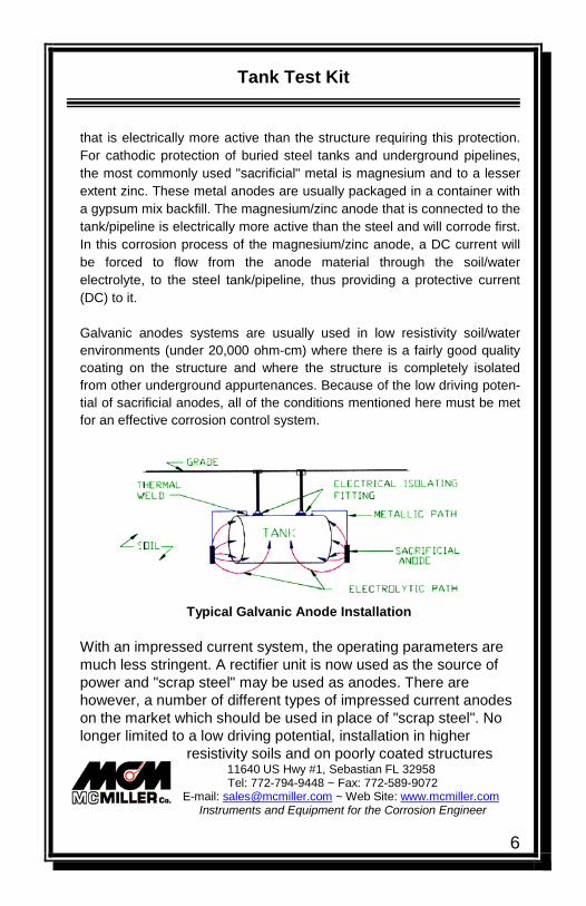
that is electrically more active than the structure requiring this protection. For cathodic protection of buried steel tanks and underground pipelines, the most commonly used "sacrificial" metal is magnesium and to a lesser extent zinc. These metal anodes are usually packaged in a container with a gypsum mix backfill. The magnesium/zinc anode that is connected to the tank/pipeline is electrically more active than the steel and will corrode first. In this corrosion process of the magnesium/zinc anode, a DC current will be forced to flow from the anode material through the soil/water electrolyte, to the steel tank/pipeline, thus providing a protective current (DC) to it. Galvanic anodes systems are usually used in low resistivity soil/water environments (under 20,000 ohm-cm) where there is a fairly good quality coating on the structure and where the structure is completely isolated from other underground appurtenances. Because of the low driving poten-tial of sacrificial anodes, all of the conditions mentioned here must be met for an effective corrosion control system.
Typical Galvanic Anode Installation With an impressed current system, the operating parameters are much less stringent. A rectifier unit is now used as the source of power and "scrap steel" may be used as anodes. There are however, a number of different types of impressed current anodes on the market which should be used in place of "scrap steel". No longer limited to a low driving potential, installation in higher
resistivity soils and on poorly coated structures

Tank Test Kit
11640 US Hwy #1, Sebastian FL 32958 Tel: 772-794-9448 ~ Fax: 772-589-9072
E-mail: [email protected] ~ Web Site: www.mcmiller.com Instruments and Equipment for the Corrosion Engineer
7
may now be accomplished. Electrical isolation is usually no longer required; however, the need for bonding to insure electrical continuity within the system would be required. Extra care must be taken while performing the survey on this type of system to insure all affected structures are sufficiently and effectively "tied" together (bonded together with a wire or cable specifically installed for the purpose of making the structures electrically continuous).
Typical Impressed Current CP Installation Both the galvanic anode system and the impressed current systems of CP has specific application in corrosion control. The above listed parameters of both systems are generalized. Individual installations will vary and would be beyond the scope of this procedure and for the individual CP tester or maintainer to become involved with at this time.
Corrosion Control Monitoring Galvanic Anode System
The monitoring of a galvanic (sacrificial-passive) anode system requires the measurement of the tank/piping to earth potentials using a high input impedance voltmeter and a copper-copper sulfate (CUCUSO4)
reference electrode. Use the M.C. Miller Co., Inc.

Tank Test Kit
11640 US Hwy #1, Sebastian FL 32958 Tel: 772-794-9448 ~ Fax: 772-589-9072
E-mail: [email protected] ~ Web Site: www.mcmiller.com Instruments and Equipment for the Corrosion Engineer
8
potential TANK TEST meter, or digital multi-meter model LC-4, which are designed and built specifically for this purpose. The MCM model RE-5, CUCUSO4 reference electrode comes with the TANK TEST potential meter and may be purchased separately as an extra and/or used with the LC-4 meter. The RE-5 plug is interchangeable. If you choose to use the pointed tip version, order the RE-5C model. Galvanic anodes systems should be monitored annually to ensure the operational effectiveness of the CP system and to determine whether any malfunctions have occurred with the anode system or with any electrical isolating fittings. The potential TANK TEST meter is used primarily for measuring the DC structure-to-earth potentials of various types of buried or submerged metallic structures, such as tanks and pipelines. The meter may be used to measure potentials in the 0-2V range or in the 0-20V range. It may be used with the CuCuSO4 reference electrode attached to the base of the meter or as a two (2) lead meter by removing the electrode and attaching the separate green test lead by its 1/4-20 stud to the meter. With the separate test lead (green) wire attached in place of the electrode, the meter may be used to measure direct-current potentials, such as anode-to-structure, structure-to-structure, or potentials across an insulating flange. Used in this fashion, the threaded female receptacle within the base of the meter is the negative input terminal of the unit. The 8' long orange (or red) test lead is the positive terminal, which plugs into the banana jack receptacle within the base of the meter. However, any length of test lead wire with a standard banana plug attached may be substituted if desired. The input resistance of the TANK TEST meter is 10 megohm (10 million ohms). Therefore, all readings taken should be very accurate, including where extremely high-resistivity soils such as dry sand or gravel are encountered or on top of concrete paving. An AC rejection filter is built into the amplifier module to reject power system AC.

Tank Test Kit
11640 US Hwy #1, Sebastian FL 32958 Tel: 772-794-9448 ~ Fax: 772-589-9072
E-mail: [email protected] ~ Web Site: www.mcmiller.com Instruments and Equipment for the Corrosion Engineer
9
Recommended Test Procedure for Tank-toSoil Potential Readings
1)
a. The meter will have a 9V battery already installed. Press and hold the 2V range button. The display will show “.000” or “.001” immediately or within a few seconds. If there is no display, the battery needs to be replaced. The battery should also be replaced if the battery symbol is displayed on the LCD. How to replace the 9V battery: To gain access to the battery, slide the orange plastic cover from the top end of the meter and remove (and save) the three 4-40 screws from the meter bezel. Gently withdraw the meter from its case. Next, remove the spring retaining clip and remove the battery. Insert a new battery and replace the spring clip. Finally, insert the meter back into its case, make sure that the LCD is aligned for convenient reading, re-install the 3 screws and replace the orange plastic cap.
b. The optional MCM LC-4 meter has its own internal battery check circuitry and will display "10 batt", which indicates the internal battery voltage has dropped below 6.8 volts and replacement is now required. A separate owners/maintenance manual is available for the LC-4 meter..
c. The CUCUSO4 electrode as shipped from M.C. Miller
Co., Inc. contains no liquid, but there are blue copper sulfate crystals in the LEXAN ® tube. Use the following steps to prepare the electrode for use:
I. Remove the plastic cap and copper rod assembly
II. Fill the tube to the top with either distilled water or MCM's anti-freeze solution
III. Replace the copper rod assembly and tighten the

Tank Test Kit
11640 US Hwy #1, Sebastian FL 32958 Tel: 772-794-9448 ~ Fax: 772-589-9072
E-mail: [email protected] ~ Web Site: www.mcmiller.com Instruments and Equipment for the Corrosion Engineer
10
plastic cap firmly to effectively seal the tube. Try to avoid getting crystals on the threaded portion of the tube as they may prevent obtaining an effective seal.
IV. The electrode should be shaken a few times to make sure that a saturated solution is obtained. The solution will be blue in color and there should always be some excess copper-sulfate crystals in the solution
V. Allow at least 24 hours for the electrode potential to stabilize. The porous plug at the end of the cell will become wet before using it for the first time. Initially, some liquid may seep from the plug assembly but will stop when the pressure inside the electrode equalizes with atmospheric pressure. Always keep the protective cap on the plug assembly when not in use.
2) A direct connection to the underground tank/structure must be made for potential testing. The connection must be made to a clean surface to ensure good electrical contact.
a. Some new tanks are equipped with a test wire for this purpose. Check all fill boxes and/or with owner-installer for location of this wire (if installed).
b. If no test station or tank test lead is found, this alternate procedure may be used to make contact. The connection to the tank itself can be made by attaching a pointed metal rod affixed with a test lead wire to a wooden tank gauging stick. Lower this stick (with the pointed rod and test wire attached) through a tank opening. Be sure to make contact with the internal tank steel surface at this point. c. On underground pipelines, the connections may be made at
the submersible pump (if there) or at the pump dispenser. Make sure you check for isolating fittings. Read and record potential measurements on both sides of this electrical isolating device. Insure the contact surface is clean and free of all dirt, oil, paint, etc.

Tank Test Kit
11640 US Hwy #1, Sebastian FL 32958 Tel: 772-794-9448 ~ Fax: 772-589-9072
E-mail: [email protected] ~ Web Site: www.mcmiller.com Instruments and Equipment for the Corrosion Engineer
11
Typical Locations For A Singular Buried Tank
3) Placement of the CUCUSO4 reference electrode should be in a relatively clean soil area over the tank (use of the fill/gauging box near one end of the tank is suggested).
a. Contaminated soil may yield erroneous readings. b. If no clean soil areas are available, placement of the reference cell in or near a wetted crack, separation or joint near the tank end, would be an alternate suggested location.
Typical Meter Hook-up and Reference Cell Placement
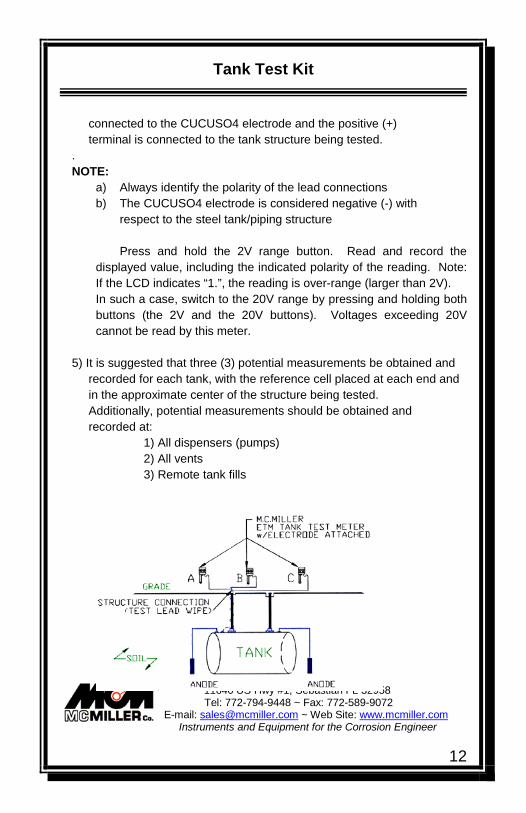
4) The test meter is connected so that the negative (-) terminal is
Tank Test Kit
11640 US Hwy #1, Sebastian FL 32958 Tel: 772-794-9448 ~ Fax: 772-589-9072
E-mail: [email protected] ~ Web Site: www.mcmiller.com Instruments and Equipment for the Corrosion Engineer
12
connected to the CUCUSO4 electrode and the positive (+) terminal is connected to the tank structure being tested. . NOTE:
a) Always identify the polarity of the lead connections b) The CUCUSO4 electrode is considered negative (-) with
respect to the steel tank/piping structure Press and hold the 2V range button. Read and record the
displayed value, including the indicated polarity of the reading. Note: If the LCD indicates “1.”, the reading is over-range (larger than 2V). In such a case, switch to the 20V range by pressing and holding both buttons (the 2V and the 20V buttons). Voltages exceeding 20V cannot be read by this meter.
5) It is suggested that three (3) potential measurements be obtained and recorded for each tank, with the reference cell placed at each end and in the approximate center of the structure being tested. Additionally, potential measurements should be obtained and recorded at:
1) All dispensers (pumps) 2) All vents 3) Remote tank fills

Tank Test Kit
11640 US Hwy #1, Sebastian FL 32958 Tel: 772-794-9448 ~ Fax: 772-589-9072
E-mail: [email protected] ~ Web Site: www.mcmiller.com Instruments and Equipment for the Corrosion Engineer
13
Measurement of Potential Directly Over A Buried Tank .
Simplified Test Procedure: I) Make sure the reference cell is snugly attached to the meter and the (orange or red) test lead wire is plugged into the meter 2) Connect lead wire with hippo clip to cleaned surface on the structure to be tested. 3) Remove the protective cap from the reference cell. 4) Contact the clean earth with the reference electrode. 5) Depress the 2V range button on the base of the meter. 6) Record the potential measurement and release the button. 7) Proceed to the next test location.
Corrosion Control Monitoring Impressed Current System
The monitoring of an impressed current CP system, involves the same basic procedures used for a galvanic anode system. However, there are several additional procedures or steps, which must be performed before, during, and after the complete checkout. A complete checkout of the impressed current rectifier unit must be made to ensure proper operation. Perform a visual inspection of the unit looking for :
1. Obvious physical and/or electrical damage. Repair as required restoring it to full operation. This may require some special electrical or electronic skills and should only be performed by qualified personnel. However, replacing a fuse or tightening some connections may be performed by the test technician or mechanic on the job.
2. With an external portable voltmeter (LC-4), measure the output terminal voltage and compare it to the panel voltmeter reading. Note and log the reading. If there is a discrepancy of more than I or 2 volts between your portable meter and the panel meter, note and log both measurements.

Tank Test Kit
11640 US Hwy #1, Sebastian FL 32958 Tel: 772-794-9448 ~ Fax: 772-589-9072
E-mail: [email protected] ~ Web Site: www.mcmiller.com Instruments and Equipment for the Corrosion Engineer
14
Typical Front Panel of an Air Cooled CP Rectifier Unit
3) Measure the protective output current. This may be done in either of two ways.
a. With the power turned off to the rectifier unit, Disconnect either the positive (+) or negative ( -) cable and insert an ammeter in series between the disconnected cable and terminal post. Be sure that the ammeter is set on a high enough range so as not to damage anyone's equipment. The rectifier's panel ammeter should give you an idea of the operating and maximum output that may be expected. Energize the unit and log the current measured. Note: There might be a slight discrepancy in output measured on the positive leg vs. the negative leg. The difference, if noticed, will usually be small and negligible.
b. With the power on, connect a milli-voltmeter across the terminals of the shunt on the panel of the rectifier unit. Read and record this measurement. From the shunt itself, obtain its

Tank Test Kit
11640 US Hwy #1, Sebastian FL 32958 Tel: 772-794-9448 ~ Fax: 772-589-9072
E-mail: [email protected] ~ Web Site: www.mcmiller.com Instruments and Equipment for the Corrosion Engineer
15
rating [(amps/mv) or (resistance)] and make the appropriate calculations. ie; 10 milli-volts read across shunt shunt rating = 25amp/5Omv , shunt factor = .5(amp/mv) current flowing (I) = milli-volt (E) x shunt factor
(I) = 10 x 0.5 = 5 amperes
ie; 7.5 milli-volts read across shunt shunt rating = 0.001 ohms current flowing (1) = milli-volts (E) 1 shunt resistance (I) = 0.0075/0.001 = 7.5 amperes
4) Install a current interrupter in the output circuit of the rectifier unit, in order to automatically cycle the unit "off' and "on". Make sure the unit is turned off before making this connection. Turn the unit back on for testing afterwards.
5) The testing of the system (as outlined in items 1 through 5 of the procedure under the galvanic anode system) may now be followed. The major difference is that both "off' and "on" potential measurements must be obtained and recorded at all test locations.
6) Upon the completion of all testing, de-energize the rectifier unit, remove the current interrupter, re-connect all wiring and re-energize the unit. Be sure to check the rectifier output (current and voltage) again, before leaving.
Tank Test Kit
11640 US Hwy #1, Sebastian FL 32958 Tel: 772-794-9448 ~ Fax: 772-589-9072
E-mail: [email protected] ~ Web Site: www.mcmiller.com Instruments and Equipment for the Corrosion Engineer
16
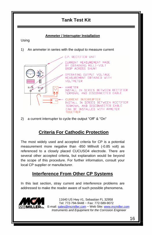
Ammeter / Interrupter Installation Using 1) An ammeter in series with the output to measure current
2) a current interrupter to cycle the output "Off" & "On"
Criteria For Cathodic Protection The most widely used and accepted criteria for CP is a potential measurement more negative than -850 Millivolt (-0.85 volt) as referenced to a closely placed CUCUSO4 electrode. There are several other accepted criteria, but explanation would be beyond the scope of this procedure. For further information, consult your local CP supplier or manufacturer.
Interference From Other CP Systems In this last section, stray current and interference problems are addressed to make the reader aware of such possible phenomena.

Tank Test Kit
11640 US Hwy #1, Sebastian FL 32958 Tel: 772-794-9448 ~ Fax: 772-589-9072
E-mail: [email protected] ~ Web Site: www.mcmiller.com Instruments and Equipment for the Corrosion Engineer
17
Stray DC current is evidenced by potential fluctuations on the structure being tested. The common sources are electrified railroad systems, welding operations, or at/near locations where DC equipment is being used. Galvanic Anode Systems Generally, interference from a galvanic anode system is not found. Due to the low driving potential (voltage) of the anodes themselves, (approximately 1.70 volts for galvomag, 1.50 volts for commercial magnesium, and 1.10 volts for zinc) and the close placement of the anodes to the structure being protected. DC current flow between the anode and the structure is not usually "lost" to other underground structures or is not of a sufficient magnitude to cause a problem. Impressed Current Systems Driving voltages from impressed current systems are generally much higher than those of galvanic anode systems and anode placement would be at more remote locations. Therefore, DC current flow between the anodes of an impressed current system and the structure being protected may be subject to an interference problem. Not all of the current being discharged by the anodes is being received by the structure requiring this current for protection. Some DC current may be "lost" to other underground structures. The concern is generated when the magnitude of this "lost" current to a foreign structure causes a detrimental effect. The pick up of current on the foreign structure would be considered protective to it. However, the current not belonging there will want to be discharged from this structure (at another location) and returned to its original source. At that point of discharge, accelerated corrosion will most likely occur. There are numerous papers and books written on this subject alone. Those interested are encouraged to pursue this subject

Tank Test Kit
11640 US Hwy #1, Sebastian FL 32958 Tel: 772-794-9448 ~ Fax: 772-589-9072
E-mail: [email protected] ~ Web Site: www.mcmiller.com Instruments and Equipment for the Corrosion Engineer
18
through outside material, since it is beyond the scope of this manual and was intended only to make the reader aware of this phenomenon.
Disclaimer The M.C. Miller Co., Inc. issues this reference guide in conformance with the best current technology regarding this specific subject. This reference guide represents a consensus of all those individuals involved in reviewing this document. It is intended as a guide only to those with some experience with corrosion control CP test techniques. M.C. Miller Co., Inc. assumes no responsibility for the interpretation or use of this reference guide. Users of this guide are responsible for reviewing appropriate health, safety, and regulatory documents and for determining their applicability in relation to this reference guide prior to its use.


![[XLS]dep.ky.govdep.ky.gov/formslibrary/Documents/TankSpreadsheetv6a.xls · Web viewHints Glossary Tank#10 Tank#9 Tank#8 Tank#7 Tank#6 Tank#5 Tank#4 Tank#3 Tank#2 Tank#1 Summary Instructions](https://static.fdocuments.in/doc/165x107/5ab43ede7f8b9a1a048ba1de/xlsdepky-viewhints-glossary-tank10-tank9-tank8-tank7-tank6-tank5-tank4.jpg)