Tandem Spin-Arc Process Development for Agile Fillet ... · Tandem Spin-Arc Process Development for...
64
May 7, 2004 EWI Project No. 47261 GTH Contract No. 2004-340 Tandem Spin-Arc Process Development for Agile Fillet Welding of Ship Structures Government Purpose Rights DISTRIBUTION STATEMENT A. Approved for public release; distribution is unlimited. Submitted to: Advanced Technology Institute (ATI) Charleston, SC
Transcript of Tandem Spin-Arc Process Development for Agile Fillet ... · Tandem Spin-Arc Process Development for...

May 7, 2004 EWI Project No. 47261 GTH
Contract No. 2004-340
Tandem Spin-Arc Process Development for Agile Fillet Welding of Ship
Structures
Government Purpose Rights
DISTRIBUTION STATEMENT A. Approved for public release; distribution is unlimited.
Submitted to:
Advanced Technology Institute (ATI) Charleston, SC

Report
Project No. 47261 GTH ATI Subcontract No. 2004-340
on
Tandem Spin-Arc Process Development for Agile Fillet Welding of Ship Structures
to
Advanced Technology Institute (ATI) Charleston, SC
May 7, 2004
Joseph Dierksheide and Dennis D. Harwig, Ph.D. EWI
1250 Arthur E. Adams Drive Columbus, OH 43221
Nick Evans and Lee Kvidahl
Northrop Grumman Ship Systems, Ingalls Operations P.O. Box 149
Pascagoula, MS 39568
Tim Nacey Panasonic Factory Automation
Welding & Robotics 1711 N. Randall Road
1E-10 Elgin, IL 60123
Government Purpose Rights
DISTRIBUTION STATEMENT A. Approved for public release; distribution is unlimited.

47261GTH/R-1/04 i
Contents
Page
Executive Summary ..................................................................................................................... iv
1. 0 Introduction ........................................................................................................................... 1
2. 0 Background........................................................................................................................... 2 2.1 FCAW.................................................................................................................................. 3 2.2 T-GMAW ............................................................................................................................. 4 2.3 RE-GMAW........................................................................................................................... 6 2.4 RLT-GMAW......................................................................................................................... 7
3. 0 Objectives ............................................................................................................................. 8
4. 0 Approach...............................................................................................................................8 4.1 Experimental Setup ............................................................................................................. 9
4.1.1 Weld Specimens........................................................................................................... 9 4.1.2 Equipment Setup .......................................................................................................... 9 4.1.3 Electrode and Shielding Gas ...................................................................................... 10 4.1.4 Seam Tracking Capability Tests ................................................................................. 10 4.1.5 ARCWISE™ Procedure Development........................................................................ 10 4.1.6 Reinforcement Factor Development ........................................................................... 11
4.2 RE-GMAW Procedure Development ................................................................................. 11 4.2.1 Setup Parameters....................................................................................................... 11 4.2.2 ARCWISE™ Test Matrices......................................................................................... 12
4.3 RLT-GMAW Experimental Procedure ............................................................................... 12 4.3.1 Setup Parameters....................................................................................................... 12 4.3.2 ARCWISE™ Test Matrices......................................................................................... 13 4.3.3 Deposition Rate Ratio Establishment ......................................................................... 14
4.4 Economic Analysis ............................................................................................................ 14
5. 0 Results ................................................................................................................................ 14 5.1 Seam Tracking Capability Tests........................................................................................ 14 5.2 RE-GMAW Results............................................................................................................ 15 5.3 RLT-GMAW Results.......................................................................................................... 16
5.3.1 Results for 3-mm Fillet Welds..................................................................................... 16 5.3.2 Results for 4-mm Fillet Welds..................................................................................... 17 5.3.3 Results for 6-mm Fillet Welds..................................................................................... 17 5.3.4 Results for 8-mm Fillet Welds..................................................................................... 17 5.3.5 ARCWISE™ Data Table and Plots............................................................................. 17
5.4 R Factor Results................................................................................................................ 18 5.5 Economic Analysis Results ............................................................................................... 18
6. 0 Discussion........................................................................................................................... 19
7. 0 Conclusions ........................................................................................................................ 20
8. 0 References.......................................................................................................................... 21

47261GTH/R-1/04 ii
Contents (Continued)
Page Appendix
Appendix A – ARCWISE™ Data and Charts
Tables
Table 1. Economic Analysis Results ..................................................................................... 22
Table 2. Preferred Process Parameters for RE- and RLT-GMAW........................................ 22
Figures
Figure 1. Setup for Double-Sided FCAW Tests with Mechanical Seam Tracking.................. 23
Figure 2. 3-mm Bead Shape Map Obtained with FCAW........................................................ 23
Figure 3. 4-mm Bead Shape Map Obtained with FCAW........................................................ 24
Figure 4. 5-mm Bead Shape Map Obtained with FCAW........................................................ 24
Figure 5. Recommended CTWD Trend Based on Fillet Weld Size for FCAW to Control Wire Cast Effects..................................................................................................... 25
Figure 6. T-GMAW Torch ....................................................................................................... 25
Figure 7. Plasma Jet-Induced Defect Characteristic of High-Speed Single Electrode GMAW..................................................................................................................... 26
Figure 8. 4-mm Bead Shape Map Obtained with T-GMAW.................................................... 26
Figure 9. 5-mm Bead Shape Map Obtained with T-GMAW.................................................... 27
Figure 10. RE-GMAW Torch and Servo-Motor Unit ................................................................. 27
Figure 11. Schematic of RE-GMAW......................................................................................... 28
Figure 12. Current Waveforms of RE-GMAW........................................................................... 28
Figure 13. Panasonic VR-006 6-Axis Robot............................................................................. 29
Figure 14. Panasonic HM-350 Pulse GMAW Power Supply .................................................... 29
Figure 15. RLT-GMAW Torch Configuration ............................................................................ 30
Figure 16. RLT-GMAW Torch Bracket Design ......................................................................... 30
Figure 17. RE-GMAW Bead Shape Map for 3-mm Fillet Welds ............................................... 31
Figure 18. RE-GMAW Bead Shape Map for 5-mm Fillet Welds ............................................... 31

47261GTH/R-1/04 iii
Contents (Continued)
Page
Figure 19. RLT-GMAW Bead Shape Map for 3-mm Fillet Welds ............................................. 32
Figure 20. RLT-GMAW Bead Shape Map for 4-mm Fillet Welds ............................................. 32
Figure 21. RLT-GMAW Bead Shape Map for 6-mm Fillet Welds ............................................. 33
Figure 22. RLT-GMAW Bead Shape Map for 8-mm Fillet Welds ............................................. 33
Figure 23. Cross Section of a 3-mm Fillet Weld Developed with 1.1/1.1-mm Diameter Electrode Combination using RLT-GMAW.............................................................. 34
Figure 24. Economic Analysis Results Comparing Number of Panels for Various Fillet Welding Processes.................................................................................................. 35
Figure 25. Preferred Travel Speeds for FCAW, T-GMAW, RE-GMAW, and RLT-GMAW ....... 35
Figure 26. Preferred Deposition Rates for FCAW, T-GMAW, RE-GMAW, and RLT-GMAW ...36

47261GTH/R-1/04 iv
Executive Summary New ship designs are calling for complex, lightweight panels made of thinner steel (as thin as 3 mm) for weight and structure optimization. For stiffener welding on ship panels, thin steel demands small, precision fillet welds in order to reduce panel distortion and improve downstream processes. The existing panel welding systems in most shipyards use flux-cored arc welding (FCAW) with mechanical seam tracking and cannot cope with the complexity and precision required. Tandem gas metal arc welding (T-GMAW) has shown an increase in deposition rate of up to three times that of single electrode GMAW while at the same time offering process robustness. However, when T-GMAW was combined with through-the-arc (TTA) seam tracking by weaving, the travel speed was limited to 1 m/min and the minimum fillet weld size was 5 mm. Rotating electrode (RE) GMAW uses TTA seam tracking by rotating the contact tip and electrode around a small diameter at 10 to 100 Hz. This method results in increased seam tracking capability while making welds as small as 2 mm at travel speeds as high as 2.5 m/min. RE-GMAW is also a robust process with enhanced bead shape characteristics ideal for horizontal fillet welds. However, since RE-GMAW is a single electrode process, it cannot match the deposition rates of T-GMAW. This project developed rotating lead tandem (RLT) GMAW, which is a new process that offers deposition rates comparable to T-GMAW with the seam tracking capability of RE-GMAW. An objective was to develop the preferred torch setup and electrode conditions that provide a complete range of fillet welds sizes for agile processing of ship structures. Procedures were developed for 3-, 4-, 6-, and 8-mm fillet welds with RLT-GMAW using the ARCWISETM procedure development method on a seam tracking T-joint test. Process robustness was assessed by evaluating fusion quality, leg size, convexity, process stability, and spatter susceptibility. A preferred torch setup was determined that met the project objective. RLT-GMAW was shown to offer deposition rates that were near or equal to standard T-GMAW, especially on smaller 3- and 4-mm fillets. While offering high deposition rates, it also demonstrated high-resolution seam tracking at travel speeds up of 2.3 m/min on 3-mm fillets.

47261GTH/R-1/04 1
1.0 Introduction The current state of shipbuilding is undergoing changes in ship design and the way ships must be built. Ship designs are being optimized according to their weight and required strength. Significant dead weight is being taken out, allowing more capacity for artillery, personnel, equipment, and cargo while improving fuel economy. As an example, at Northrop Grumman Ship Systems (NGSS) Avondale Operations, the production weight percentage of thin (<10 mm thickness) to thick steel is rising to over 90% on certain ship designs.(1) A problem exists, however, as the complexity of the new designs is being passed on to manufacturing. Existing production systems are not designed for fabricating lightweight complex designs. In particular, the panel lines lack proper foundation, precision welding, and flexible tooling required to maintain accuracy and inhibit distortion. Most U.S. shipyard production systems were designed to fabricate structures from plate 10- to 30-mm thick or thicker. Current panel welding systems are focused on welding heavy plate with mechanical seam tracking. An over-welding approach is used at most shipyards to accommodate errors in mechanical seam tracking and fitup errors; these over-size welds are a significant cause of weld-induced distortion and excess welding costs. Current and future ship programs, including the Navy’s DDG, DD(X), and LPD, and the Coast Guard’s Deepwater, will deploy more thin plate (3 to 10 mm) to optimize weight. To yield first-time weld quality and minimize distortion on complex panel fabrications, shipyards must be able to precisely and accurately produce a range of specified fillet weld sizes (3 to 8 mm). High-speed welding processes, such as tandem gas metal arc welding (T-GMAW), can consistently produce fillet welds sizes of 5 mm or larger. This can reduce weld heat input and distortion by over 50%, and increase travel speed by a factor of four compared to over-welding using single wire flux-cored arc welding (FCAW). Accurate high-speed seam tracking is a prerequisite to optimizing weld size for each application. However, conventional through-the-arc (TTA) seam tracking that is used routinely with robotic T-GMAW cannot track small fillet welds (3 to 5 mm) due to equipment inertia and sensor noise. This lag in automated seam tracking inhibits the application of small fillets (≤5 mm) on optimized ship panels using this process. A new approach, rotating electrode (RE) sensing, has emerged to bridge the technology gap in high-speed seam tracking of small fillets. Developed by NKK in Japan for commercial shipbuilding, this technique uses TTA sensing with a rotating contact tip rather than torch oscillation. As a result, the sensor has five times the sensitivity of conventional TTA weaving

47261GTH/R-1/04 2
techniques. This allows seam tracking at greater travel speeds and application of smaller fillets than those achieved with TTA weaving with tandem or other GMAW variants. Rotating electrode torches are sized for discrete fillet weld size ranges, since the electrode spin diameter is fixed in the torch. This flexible approach supports a lean and agile shipbuilding enterprise by deploying a range of weld sizes at the highest speeds possible with simple process tooling changes and minimal setup times. To summarize, reliably meeting manufacturing needs in the small batch-mixed production environment of military shipbuilding required a new arc welding approach that will (1) easily accommodate the multiple parameter-torch setups needed for the full range of fillet weld sizes and (2) dependably provide seam tracking at high production rates. This project proposed to integrate the excellent seam tracking – small fillet performance of RE-GMAW with a high deposition trailing GMAW torch to develop a new variant of T-GMAW. If successful, it was believed that the rotating lead tandem (RLT) – GMAW process will offer the best weld quality, seam tracking performance, and productivity over the full range of fillet weld sizes (3 to 8 mm) for panel construction. The goal was a new process supporting a flexible manufacturing environment by deploying a range of weld sizes at the highest speeds possible without any process tooling changes. This will provide a lean and agile capability for shipbuilders to produce transformational ship structures.
2.0 Background Typical panel lines consist of a butt welding station, a stiffener fitting station, and a stiffener welding station. The stiffener welding station usually consists of a gantry system with two FCAW torches, one for each side of the stiffener for making double-sided welds simultaneously. The torches are guided along the welding joint by wheels that ride along the stiffener joint. This mechanical seam tracking was not designed to account for beam waviness, which is common on lightweight stiffeners. While existing panel weld station have been sufficient for past operations, they are no longer tolerant to the demands of modern ship designs.(1,2)
Studies have established a relationship between welding heat input and induced distortion. In general, high heat input welds lead to higher levels of distortion. Therefore, when optimizing the plate and stiffener thickness of a panel, it is essential to optimize the weld size accordingly. For instance, some panels are designed with steel as thin as 3 mm. A small 3-mm fillet weld would be ideal to ensure minimum distortion when welding lightweight stiffeners to this thin panel. Thin steel that is to be used on ship panels calls for small, precision fillet welds.

47261GTH/R-1/04 3
A review of welding processes that can be used for precision fillet welding of ship panels was performed to assess the benefits of the RLT-GMAW process. This review assessed the state of the art with FCAW and T-GMAW. Seam tracking technology that can be applied with each process was also reviewed since this can often limit the productivity potential of welding processes. 2.1 FCAW FCAW is used for most stiffener welding stations on shipbuilding panel lines. Seam tracking along the joint is by mechanical guide wheels that ride along the joint. FCAW is a robust process, ideal for large welds at low travel speeds. The process is tolerant to primed surfaces as the flux collects and drives out excess oxygen and other unwanted impurities in the weld, shields the weld pool from the atmosphere, and provides a fast-freezing slag that supports the solidifying bead. FCAW is also relatively cheap to operate. A simple constant voltage (CV) power supply is all that is needed to deliver arc power. Plus the ideal shielding gas is CO2, which is cheaper than Ar-CO2 mixes. Weld tests made with FCAW in a prior investigation(2) using mechanical seam tracking were performed to develop ARCWISE™ data sets for 3-, 4-, and 5-mm fillet welds. The ARCWISE™ method provided benchmarking data by systematically evaluating the effects of arc length and travel speed on weld quality for a constant weld size application. These tests were performed on primed steel and simulated a panel line. Double-sided fillets welds were made using a welding tractor (Figure 1) that had spring loaded guide wheels on each side. The preferred welding procedures that were developed controlled the arc length and travel speed to achieve the best combination of weld bead profile and fusion quality. FCAW was determined to not be to be well suited for small, precision fillet welds. Figures 2 through 4 show bead shape maps for 3-, 4-, and 5-mm fillet welds (respectively) made with FCAW. The parameter window, Figure 4 was acceptable for 5-mm fillet welds where the best weld quality was achieved at 0.5-m/min travel speed. At this speed, the process at good tolerance to arc length and did not over penetrate gaps. For 3-mm fillet welds, the operating parameter window was limited to a single set of parameters (Figure 2 at the 1.0-m/min travel speed). Above this travel speed, the weld resulted in gross undercut. Below 1.0 m/min, there was not enough heat in the arc to result in a stable process. While the bead shape maps for 3-mm fillet welds did not show promise for FCAW, the 4- and 5-mm fillet welds showed good characteristics. Preferred parameters for 4-mm fillet welds were at a travel speed of 0.8 m/min while 5-mm fillet welds were preferred at 0.5 m/min. The bead

47261GTH/R-1/04 4
shape maps indicate that both 4- and 5-mm fillet welds had good robustness, which was quantified by the size of the operating window. A travel speed range from 0.6 to 1.0 m/min was shown for 4-mm fillet welds. For 5-mm fillet welds, the travel speed range was 0.4 to 0.8 m/min. Preferred parameters were chosen below the maximum travel speeds to allow tolerance to process variances, such as fitup gap. While FCAW showed good robustness for 4-and 5-mm fillet welds, productivity can be improved by using alternative processes. Further, an alternative process was needed for robust welding of 3-mm fillet welds. Another problem with FCAW 3-mm fillet welds was leg size control. Almost all of the 3-mm fillet welds had unequal legs as a result of tests made with mechanical seam tracking where electrode cast can not be controlled at the arc. The contact tip-to-work distance (CTWD) was optimized for the FCAW tests (Figure 5) to minimize the effects of electrode cast. Figure 5 shows an important trend established for FCAW. CTWD was optimized for each fillet weld size to account for electrode cast effects. As the weld size decreases, so must the CTWD. An 8- to 11-mm CTWD was required to make acceptable welds, but leg size control was still difficult. In addition, spatter buildup on the shielding cup became a noise variable when using a CTWD this small. Mechanical seam tracking with integral torch mount tooling does not allow for easy CTWD changes during production. This is a problem with current shipbuilding gantries that use FCAW and do not possess the agility required for multiple fillet weld sizes.(1)
2.2 T-GMAW One process alternative to FCAW is T-GMAW (Figure 6). T-GMAW uses two GMAW electrodes aligned in a lead/trail fashion in one (or two) torches to enhance deposition. The process allows independent control of wire feed speed (WFS), current, voltage, and pulse parameters. This control allows optimization of penetration, bead shape, and deposition. T-GMAW resulted in up to three times the deposition rate as compared to that of FCAW.(3)
The close proximity of the arcs is fundamental to the significant increase in deposition. With the arcs close together, they were attracted toward one another, resulting in an inward direction of arc force. By directing arc force inward instead of downward (into the weld pool), plasma jet-induced defects (Figure 7) were avoided. Plasma jet-induced defects are caused by gasses being jetted into the weld pool by the downward flow of the arc. The plasma pressure is directly related to the current density. Each electrode diameter has a preferred current density range that assures proper arc stiffness and resistance to plasma jet-induced defects. Rapid cooling rates associated with high-speed welding increase the susceptibility to plasma jet-induced defects since the entrapped gas has less time to escape the solidifying weld pool.

47261GTH/R-1/04 5
As a minimum, the deposition rate of T-GMAW is at double that of FCAW since each electrode operates at a current density comparable to single electrode processes. Further deposition rate increases are made possible by arc coupling which synergistically improves the melting rate of each electrode and reduces the plasma jet force caused by using higher current densities. The reduced force coupled plasma jet provides better gap tolerance and reduced risk of burnthrough. An important parameter in T-GMAW process development is the trail-to-lead electrode WFS ratio (WFST:WFSL). This ratio has been application specific because different electrode combinations and conditions can be used in T-GMAW processes. In general, the lead electrode operates at higher currents to assure penetration at the leading edge of the weld pool where there is less liquid pool for plasma jet interaction. The trailing electrode operates at a lower current density since the susceptibility to plasma jet defects is higher at the rear of the weld pool. In systematic parameter development, like the ARCWISE™ method, where a constant deposit size is maintained for benchmarking, the total WFS-to-travel speed (TWFS:TS) ratio is held constant for T-GMAW. The WFST:WFSL ratio is also fixed as a strategy for systematic parameter study of the T-GMAW process. For precision 4- and 5-mm fillet welds, the preferred WFST:WFSL ratio was 0.5.(4) For smaller weld sizes (or at low WFS), a higher ratio may be preferred so that more power can be provided to the trail arc. This will allow the trail electrode to melt at a sufficient rate, allowing proper bead contour. Refer to Figure 8 for the 4-mm bead shape map and Figure 9 for the 5-mm bead shape map for T-GMAW. For the 4-mm fillet welds, preferred parameters were obtained at a travel speed of 1.8 m/min. Quality welds with proper sidewall fusion were made at travel speeds as low as 1.0 m/min. For the 5-mm fillet welds, preferred parameters were obtained at a travel speed of 1.5 m/min. Quality welds with proper sidewall fusion were made at travel speeds as low as 1.0 m/min. The large parameter windows for 4- and 5-mm fillet welds indicate adequate process robustness. TTA seam tracking can be employed with T-GMAW by weaving the torch while sensing arc voltage or current levels at the weave extents. The seam tracking control is integrated with the welding power supply and the torch positioner (typically a robot) to maintain the electrode in the joint. Since TTA seam tracking senses at the arc, electrode cast effects may be negated. Because of this, there is no dependence on CTWD for each weld size, providing agility for welding multiple fillet weld sizes. Limitations exist, however, when attempting to use TTA seam tracking with T-GMAW on small, precision fillet welds at high speeds. Since a sufficient signal-to-noise ratio is required when

47261GTH/R-1/04 6
using TTA seam tracking, the minimum fillet weld size was limited to 5 mm.(5) With smaller weld sizes, the variation in current and voltage throughout the weave were not significant enough to sense torch position in the joint. Further, when using a robot, the entire robot must move to manipulate the torch weave. Because of the inertia associated with weaving, a typical welding robot cannot weave faster than 5 Hz. Since the proper weave frequency is proportional to the travel speed, a maximum travel speed of only 1 m/min was achieved before loss of sensor resolution and weld bead waviness occurred.(5)
As an alternative to TTA seam tracking through weaving, a laser vision sensor may be used for seam tracking with T-GMAW. A laser seam tracker scans the weld joint ahead of the torch to determine its position and adjusts the tool point to maintain torch alignment. Because of the advances in lasers and feedback sensors, the maximum sensing speed greatly exceeds any welding speed possible with T-GMAW. However, limitations exist for laser seam tracking similar to mechanical seam tracking. With laser seam tracking, the CTWD has to be adjusted according to the weld size, as this seam tracking method does not account for electrode cast. Even though the CTWD adjustment can be made when using a robot to position the torch, the laser seam tracking still does not account for electrode cast as well as TTA seam tracking. This results in unequal leg lengths as the electrode cast varies. The susceptibility to unequal leg size from electrode cast increases with decreasing fillet weld size. T-GMAW has the potential to provide a significant productivity increase for 4- and 5-mm fillet welds. However, the higher travel speeds offered by this process cannot be deployed in a shipyard because of these seam tracking limitations. 2.3 RE-GMAW RE-GMAW is a robotic single electrode welding process that employs TTA seam tracking by electrode rotation (Figures 10 and 11). The system rotates the contact tip and hence the wire electrode around a small diameter (1.5 to 4.0 mm) at a high frequency (10 to 100 Hz). The seam tracking action functions by an integration between the robot controller, welding power supply, and feedback sensor. The feedback sensor monitors welding current or voltage and position of the electrode to maintain equal current or voltage levels at sidewall positions during each electrode revolution (Figure 12). Since only the contact tip and electrode are in motion, there are no robot inertia limitations, making high-speed TTA seam tracking a possibility. Plus, the sensor resolution is enhanced by the current and voltage waveform spikes induced by high-speed rotation. The RE-GMAW seam tracker is able to seam track while welding fillet welds as small as 2 mm. Seam tracking tests have proven the system to be capable of travel speeds of up to 2.5 m/min. As with TTA seam tracking by weaving, there is no dependence on CTWD for

47261GTH/R-1/04 7
each weld size to accommodate electrode cast. Small 3-mm fillet welds were made with the RE-GMAW process with a CTWD of 25 mm.(4) The RE-GMAW TTA seam tracking method has the agility needed for multiple fillet weld sizes. Along with the exceptional seam tracking capabilities associated with RE-GMAW, the process also offers enhanced weld bead quality and electrode burnoff characteristics. This rotating action of the arc has a stirring effect on the weld pool that allows entrapped gas to escape, reducing porosity and enabling the use of higher current densities. The rotation also increases sidewall penetration and produces a flat, uniform bead in horizontal fillet welds by directing the metal droplets outward. Further, an increase in electrode melting rate occurs from the induced centrifugal force on the droplets. The characteristics of the RE-GMAW process make it a robust system, ready for real world production. However, as with any single electrode GMAW process, the potential of RE-GMAW is limited by its deposition rate. While an increase in deposition was shown when compared to FCAW, T-GMAW still had a greater deposition rate and travel speed potential than RE-GMAW(4). 2.4 RLT-GMAW Based on the advantages and limitations of T-GMAW and RE-GMAW, a new process was developed in this project that offers the best of both processes. RLT-GMAW is a hybrid process combining the deposition characteristics of T-GMAW with the seam tracking capabilities of RE-GMAW. The process uses a RE-GMAW torch in the lead and a standard GMAW torch for the trail. During welding, two separate weld pools are formed since the arcs are not coupled intentionally. A key aspect of this project was the tooling setup for the RLT-GMAW process. Most T-GMAW processes orientate the wire electrodes in one torch so that a coupled arc is formed over the welding pool. The position of the trail torch was evaluated in this project and set so the RE-GMAW torch and sensor control functioned properly. Once the preferred torch orientations were determined to accommodate the full range of weld sizes, procedures were developed to maximize travel speed. For each weld test performed, a concurrent seam tracking capability test was performed, this assessing the robustness of the RE-GMAW seam tracking system. The objective of this project was to develop a preferred torch setup condition and a range of welding procedures for double-sided fillet welding of steel panels. The preferred torch setup was aimed at using one set of consumables for a fillet weld size range of 3 to 8 mm while

47261GTH/R-1/04 8
maximizing productivity and seam tracking robustness. Since TTA seam tracking takes place only on the lead torch, accommodation of trail electrode cast required a CTWD-to-weld size dependence for RLT-GMAW. However, unlike the existing mechanical systems, CTWD can be readily changed with an offset parameter in the sensor. By changing the CTWD, electrode cast effects of the trail arc were factored into the procedure development tests. It was envisioned that this process would offer the best agility required to fabricate a full array of weld sizes at maximum speed and robustness. The preferred RLT-GMAW procedures were benchmarked against procedures developed in this report for RE-GMAW and in past projects for FCAW and T-GMAW.(3,4,6) Good results were obtained and further optimization was demonstrated by changing the electrode combination for specific weld sizes.
3.0 Objectives 1. Develop a new welding process that supports welding thin and thick plate with precision fillet
welds in an agile and lean enterprise that optimizes the fabrication of complex ship structures.
2. Develop setup parameters the for RLT-GMAW process so seam tracking performance and
productivity are optimized for a full range of precision fillet weld sizes. 3. Determine baseline welding procedures for 3-, 4-, 6-, and 8-mm leg length fillet welds. 4. Evaluate process economics compared to conventional tandem and single electrode
processes.
4.0 Approach This project consisted of three main parts, RE-GMAW procedure development, RLT-GMAW setup parameter and tooling development, and RLT-GMAW procedure development. All RE-GMAW procedure development was done at Panasonic Factory Automation (PFA). RLT-GMAW setup parameter and tooling development took place at both PFA and EWI. All RLT-GMAW procedure development took place at EWI. RE-GMAW development was intended to assess the capabilities of the process while at the same time developing parameters that may be used for lead arc parameters with RLT-GMAW. The ARCWISE™ method(6) for parameter development was used to find the parameter windows for 3- and 5-mm fillet welds. All welds were cross sectioned and photographed to allow qualitative assessment of bead profile properties such as fusion quality, leg size, and convexity.

47261GTH/R-1/04 9
Based on the bead profile assessment, the parameter windows were qualitatively established for each weld size.(4) Quantitative analysis of bead shape, convexity, penetration, and leg size, etc. was possible but beyond the scope of this project. The process windows determine what productivity levels were feasible and are an indication of process robustness. A large window indicated a more robust process. Following RE-GMAW development, the RLT-GMAW process was assessed for four fillet weld sizes (3, 4, 6, and 8 mm), covering a wide range of sizes currently welded in shipyards. In a similar fashion to the RE-GMAW study, the ARCWISE™ method was used to study RLT-GMAW. 4.1 Experimental Setup 4.1.1 Weld Specimens For the 3-, 4-, 5-, and 6-mm fillet weld tests, sheared pieces (5 × 60 cm and 8 × 60 cm) of 5-mm-thick DH-36 steel were assembled into a T-joint to represent the stiffener-to-panel weld T-joint. For 8-mm fillet weld tests, sheared pieces of ground 10-mm-thick DH-36 steel were assembled in the same fashion. One-sided welding tests were performed on the pre-tacked T-joints clamped to a welding table. 4.1.2 Equipment Setup All RE-GMAW tests used a Panasonic VR-008 6-axis welding robot (Figure 13) equipped with a water-cooled Super Spin Arc Sensor torch (Figure 10). The rotation diameter of the contact tip may be adjusted by changing the gears within the torch, but for all tests, the rotation diameter was held constant at 2 mm. The robot controller is integrated with the Super Spin Arc Sensor System and a Panasonic HM-350 pulse GMAW power supply (Figure 14). For all tests, the power supply was set in pulse mode using the default values (no waveform adjustment was attempted). While in pulse mode, synergic parameter adjustment was possible by setting a current value and a voltage value. The current setting controlled the WFS and burnoff rate by changing the pulse waveform while the voltage setting controlled the arc length by changing the pulse frequency. For the RLT-GMAW tests, the RE-GMAW setup was used along with a Panasonic HM-500 pulse GMAW power supply, set in pulse mode, and a water-cooled GMAW torch for the trail electrode (Figure 15).

47261GTH/R-1/04 10
4.1.3 Electrode and Shielding Gas For all RE-GMAW tests, 1.1-mm-diameter ER70S-6 electrode was used. For the majority of the RLT-GMAW tests, 1.1-mm-diameter ER70S-6 electrode was used for the lead electrode while 1.3-mm diameter ER70S-6 was used for the trail electrode. An objective of this project was to recommend one setup for RLT-GMAW that provided the best combination of productivity, quality, and robustness for the full range of weld sizes. This electrode combination was preferred to improve the productivity on larger fillet welds. Higher productivity was measured on small fillet welds with an alternative 1.1/1.1-mm diameter electrode combination. The shielding gas used was 90% Ar/10% CO2 since both electrodes were operated in pulse spray mode. 4.1.4 Seam Tracking Capability Tests Seam tracking was used on all RE-GMAW and RLT-GMAW weld tests made in this investigation. All tests were performed by offsetting the end of the weld specimen by 2.5 cm from the taught path of the robot. If a weld was deposited properly in the joint, seam tracking was proven to be successful. 4.1.5 ARCWISE™ Procedure Development For both RE- and RLT-GMAW, ARCWISE™, test matrices were made for each fillet weld size, testing an array of travel speeds and arc lengths. Constant weld deposit area tests were made for each fillet weld size by maintaining a constant WFS/TS ratio. The following equation was used to determine the WFS/TS ratio:
EADA
TSWFS
= (1)
where DA is the weld deposit area and AE is the cross-sectional area of the electrode. For all tests, arc length was set by the operator by adjusting the voltage setting until the desired arc length was achieved. In general, as travel speed was increased, higher power with higher WFSs were required. Base metal dilution, nugget area and penetration were observed to increase as travel speed was increased for each weld size until the process became unstable. A qualitative assessment was made to determine the preferred parameters based on the best combination of process stability, seam tracking performance, resistance to spatter, fusion quality, and bead profile at the

47261GTH/R-1/04 11
maximum possible travel speed. Quantitative analysis of the weld tests was possible but was beyond the scope of this investigation. 4.1.6 Reinforcement Factor Development A conservative approach to weld sizing, ideal for coping with production variances, was developed in this study. A reinforcement (R) factor may be put on the right side of Eq. (1) to account for normal fitup gap and weld bead convexity. In this study, the R factor was determined based on a linear trend of measured deposit area reinforcement versus weld size. The R factor accounted for a 1-mm T-joint gap, which was the maximum preferred gap for high-speed tandem electrode processes in production. The R factor varied depending on weld size, since smaller welds required more reinforcement as a percentage of deposit area. 4.2 RE-GMAW Procedure Development 4.2.1 Setup Parameters Before welding procedure development began, setup parameters were established and held constant for all of the RE-GMAW procedure development. These parameters include travel angle, work angle, Spin Arc sensor parameters, and CTWD. A 10-degree push travel angle was used for all weld tests to enhance the RE-GMAW sensor resolution. Using a push angle allowed the front of the arc to be on top of unwelded base metal so that current and voltage change significantly as the arc was rotated across the joint. If a pull travel angle was used, the arc may be completely on top of the weld pool, leading to low resolution in current feedback readings. Further, for solid electrode GMAW processes, a push travel angle promotes optimized weld bead shape by reducing convexity. A 45-degree work angle promotes equal leg length for small, horizontal fillet welds. For fillets larger than 5 mm, a larger work angle may be desired to push more metal onto the top leg offsetting the effects of gravity. Five parameters were adjusted and maintained for the Spin Arc sensor. The parameters included rotation frequency (20 to 100 Hz), sensor gain 1 (-99 to + 99), sensor gain 2 (-99 to +99), sensor offset 1 (-15 to +15), and sensor offset 2 (-15 to +15). Sensor gain values determined how fast the robot controller moved as a reaction to changes in current feedback readings, with -99 being the slowest and +99 being the fastest. Sensor offset values changed the position of the torch relative to the joint. Gain 1 and offset 1 related to the position of the torch in the direction perpendicular to the joint and the electrode (along the sidewalls). Gain 2

47261GTH/R-1/04 12
and offset 2 related to the position of the torch in the direction of the axis of the electrode (CTWD). Ideally, the TTA seam tracking method employed by the Spin Arc sensor should negate electrode cast effects because it tracks at the arc. In order to evaluate the true capability of the sensor, all RE-GMAW fillet weld tests used a 25-mm CTWD. This length of CTWD would not be used in production, especially for small fillet welds. These tests were designed, in part, to assess how well the electrode cast was accounted for with RE-GMAW TTA seam tracking. 4.2.2 ARCWISE™ Test Matrices ARCWISE™ tests were made with a constant deposit area for each weld size. For 3-mm fillet welds, the travel speed range was from 0.5 to 1.8 m/min. For 5-mm fillet welds, the travel speed range was 0.5 to 1.3 m/min. Travel speed was limited on the low end by the stability of electrode burnoff and improper fusion. The upper end was limited by weld pool stability and the onset of bead convexity and undercut. Arc lengths of 1 and 3 mm were tested for both weld sizes. For all tests, arc length was set by the operator by adjusting the voltage setting until the desired arc length was achieved. Current and voltage was recorded with the internal data acquisition system of the Panasonic robot. The readings obtained were average values and allowed the formation of ARCWISE™ data plots. 4.3 RLT-GMAW Experimental Procedure 4.3.1 Setup Parameters Before welding procedure development began, setup parameters were established and held constant for all of the RLT-GMAW procedure development. These parameters included lead and trail travel angles, torch offset distance, work angle, Spin Arc sensor parameters, and CTWD. RLT-GMAW torch setup parameters had to work for the entire range of weld sizes. The offset distance and travel angles were:
• Determined based on using the rotating lead electrode for seam tracking (Section 4.2.1). • Developed to minimize the distance between electrodes to minimize seam tracking error
on stiffeners that have waviness. • Set far enough apart so that the trailing weld pool did not interfere with the Spin Arc
sensor control of the rotating lead electrode.

47261GTH/R-1/04 13
The preferred electrode spacing distance was found to be 2.5 cm (at the arcs) at a nominal 19-mm CTWD. The preferred lead travel angle was found to be 10-degree push, while the preferred trail travel angle was 20-degree push. Once the torch setup parameters were established, a production-ready bracket was designed and fabricated (Figure 16). The design calls for two two-piece steel clamps, one for the top of the torches, and one for the bottom, near the gas nozzles. The bottom clamp must maintain electrical isolation between the two torches to avoid short circuiting through the lead gas nozzle. With two separate weld pools, a 45-degree work angle promoted equal leg length for fillet weld sizes up to 8 mm. Proper alignment of the two torches also maintained equal leg length. In a similar fashion to RE-GMAW, five parameters were adjusted for the Spin Arc sensor (Section 4.2.1). While the TTA seam tracking method employed by the Spin Arc sensor negates lead electrode cast, the trail electrode cast must be accounted for. For RLT-GMAW, CTWD was optimized for each weld size by means of changing the sensor offset 2 setting. For 3-mm fillet welds, offset 2 was set for a CTWD of 16 mm. For 4-, 6-, and 8-mm fillet welds, offset 2 was set for a CTWD of 19 mm. The other four Spin Arc sensor parameters (rotation frequency, sensor gain 1 and 2, and sensor offset 1) were maintained constant for all tests. 4.3.2 ARCWISE™ Test Matrices ARCWISE™ tests were made with a constant deposit area for each weld size. The following table shows the range of travel speeds tested for each weld size:
Fillet Weld Size (mm)
Lowest Travel Speed (m/min)
Highest Travel Speed (m/min)
3 1.0 2.5 4 0.8 2.0 6 0.8 1.5 8 0.4 0.8
Travel speed was limited on the low end by the stability of electrode burnoff and improper fusion. The upper end was limited by weld pool stability and the onset of bead convexity. For 3-, 4-, and 6-mm fillet welds, 1- and 3-mm arc lengths were tested. For 8-mm fillet welds, tests were made with 1- and 2-mm lead arc lengths and 1- and 3-mm trail arc lengths. Current, voltage, and WFS were recorded with a waveform data-acquisition system. The sample rate was set at 12,000 Hz to allow for full resolution of the waveform. The current, voltage, and WFS were averaged over 5 to 10 s and allowed the formation of ARCWISE™ data plots.

47261GTH/R-1/04 14
4.3.3 Deposition Rate Ratio Establishment A WFST:WFSL ratio was developed for the RLT-GMAW process in this project. The ratio was based on using a specific electrode combination. The ratio developed in this project was a function of fillet weld size since different electrode sizes were used for the lead and trail. This was different than prior art where a simple ratio was assumed for the entire productivity (travel speed range) of an application. In reality, the ratio may or may not need to be adjusted based on process performance. The goal in this project was to maximize arc stability and seam tracking performance of the lead electrode while maximizing deposition without tracking interference with the trail electrode. The developed trail deposition rate-to-lead deposition rate (TDR:LDR) ratio was linearly proportional to deposit area. For smaller weld sizes, the TDR:LDR ratio needed to be low so that sufficient current was put into each arc for proper seam tracking and weld pool stability. As the weld size was increased, more power was focused on the trail arc. This allowed the lead weld pool to be small enough for proper seam tracking while the trail electrode contributed more significantly to deposition. 4.4 Economic Analysis Economic analysis was performed to benchmark the FCAW, T-, RE-, and RLT-GMAW processes for shipbuilding panels. Preferred travel speeds for FCAW and T-GMAW were taken from previous work.(2,3,4) Preferred travel speeds for RE- and RLT-GMAW were developed in this study and used to benchmark the processes against FCAW and T-GMAW. Assumptions were made in the normal setup cycle times to position a welding gantry and prepare for welding, and held constant for each process. Each panel was assumed to be 15.2-m long and consisted of eight stiffeners. The time between each stiffener was assumed to be 5 min, allowing for 2 min of post-weld clamping, indexing, and positioning of the gantry. Downtime was assumed to be 48 min (10%) of the 480 min per 8-hr shift. Further assumptions could have been made for the reduced amount of rework when using TTA seam tracking, or for various weld sizes; however, that was beyond the scope of this study.
5.0 Results 5.1 Seam Tracking Capability Tests The seam tracking capability tests were successful for all RE-GMAW test welds and all but one of the RLT-GMAW test welds. The only exception was a peak travel speed test on the 8-mm fillet welds where the trail weld pool became so large that it flowed into the lead arc and caused disturbance of the sensor. For all other tests, each weld resulted in equal leg lengths along the

47261GTH/R-1/04 15
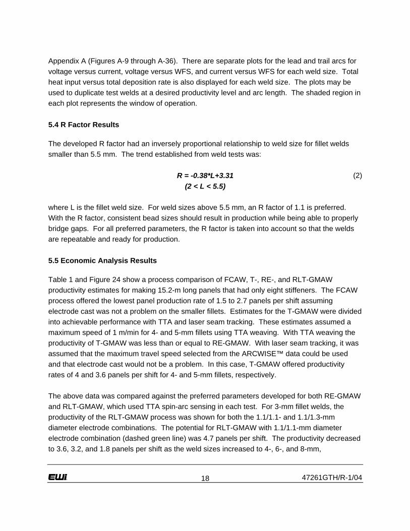
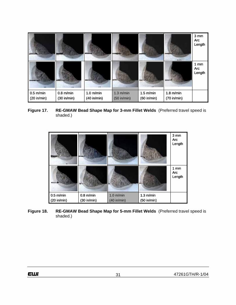
entire joint. This indicated that with proper parameters, the Spin Arc sensor and control provided excellent seam tracking. 5.2 RE-GMAW Results Refer to Figures 17 and 18 for 3- and 5-mm (respectively) ARCWISE™ bead shape maps for the RE-GMAW process. Note that for both weld sizes at low travel speeds near 0.5 m/min, there was no penetration at the root. This was the lower limitation of the process. All of the welds had good underbead shape and sidewall penetration. These favorable characteristics were a result of the electrode rotation action. The rotating electrode was also observed to improve gap bridging. The high end limitations for each weld size were related to the onset of undercut and excessive convexity. Note each weld in the bead shape maps had equal leg lengths, another advantage of the process. RE-GMAW showed sufficient accountability for electrode cast. For the RE-GMAW bead shape maps, all welds were made with a CTWD of 25 mm. While a CTWD this long would not be used in production, the weld tests demonstrated that TTA seam tracking maintained weld quality, regardless of electrode cast effects. Preferred parameters for making 3-mm fillet welds with RE-GMAW were at a travel speed of 1.3 m/min and at an arc length of 1 mm. Proper fusion and bead shape quality will result if the travel speed is stepped down to as low as 1.0 m/min. Below travel speeds of 1.0 m/min, there was insufficient penetration at the root of this T-joint application. For 3-mm fillet welds made above 1.3 m/min, the weld pool became unstable resulting in an irregular bead shape profile. Preferred parameters for 5-mm fillet welds were at 1.0 m/min at an arc length of 2 mm. Proper fusion and bead shape quality will result if travel speed is stepped down to as low as 0.8 m/min. Below travel speeds of 0.8 m/min, there was no penetration at the root. For 5-mm fillet welds made above 1.0 m/min, severe undercut and bead convexity may result. Both the 3- and 5-mm RE-GMAW bead shape maps displayed the enhanced sidewall penetration and reduced root penetration characteristic of the process. The window for RE-GMAW under the tested conditions was relatively large, including a tolerance to arc length. RE-GMAW was shown to be a robust process providing consistent leg lengths with no undercut or extreme convexity at preferred parameters. Refer to Table A-1 in Appendix A for the parameters used for all 3- and 5-mm fillet welds shown in the RE-GMAW bead shape maps. The ARCWISE™ data plots are also in Appendix A (Figures A-1 through A-8). The plots include voltage versus current, voltage versus WFS, current versus WFS, and heat input versus deposition rate for each weld size. The plots may

47261GTH/R-1/04 16
be used to duplicate test welds at a desired productivity level and arc length. The shaded region in each plot represents the window of operation. 5.3 RLT-GMAW Results Refer to Figures 19 through 22 for the RLT-GMAW 3-, 4-, 6-, and 8-mm bead shape maps. Note: at low travel speeds, there was no penetration at the root, similar to RE-GMAW. When comparing RLT-GMAW to a single electrode GMAW process, the penetration was lower for the same deposition rate, due to the reduced current density as it is split across two arcs. RLT-GMAW showed sufficient accountability for electrode cast. The considerations for electrode cast were not as extreme as required for FCAW. This was due to smaller electrode cast in larger, 1.3-mm-diameter electrode. Also, the trail electrode was directly behind the lead electrode which was aimed precisely into the weld joint. For 3-mm fillet welds, a 16-mm CTWD was found to be sufficient while 19 mm was sufficient for 4-, 6-, and 8-mm fillet welds. 5.3.1 Results for 3-mm Fillet Welds For 3-mm fillet welds (Figure 19), the preferred TDR:LDR ratio was 0.7. The best RLT-GMAW parameters were achieved at a travel speed of 1.5 m/min with a 1-mm arc length for each arc. At travel speeds above 1.5 m/min, weld pool instability results in an inconsistent bead profile throughout the weld length. At speeds below 1.0 m/min, the arc power was too low for proper fusion into the base metal. As a side-study, 1.1-mm-diameter electrode was used on the trail arc. Excellent weld quality was produced at a travel speed of 2.3 m/min (Figure 23). The arc stability was good as each electrode was operating at a preferred current density. However, the objective of this study was to have one electrode combination for all weld sizes. A 1.1/1.1-mm diameter electrode combination would not be preferred for 8-mm fillet welds. Therefore, a full ARCWISE™ matrix was not developed using the 1.1/1.1-mm diameter electrode combination. For 3-mm fillet welds, the RLT-GMAW process was not preferred when using the 1.1/1.3-mm diameter electrode combination. The fusion and penetration profiles were weak, and the trail electrode lacked arc stiffness from too low of a current density. For production, two options are recommended for 3-mm welds: (1) while keeping the 1.1/1.3 electrode configuration, use only the lead electrode as a RE-GMAW process at 1.3 m/min, or (2) change the trail electrode to 1.1-mm diameter to achieve higher travel speeds.

47261GTH/R-1/04 17
5.3.2 Results for 4-mm Fillet Welds For 4-mm fillet welds (Figure 20), preferred parameters were achieved at a travel speed of 1.5 m/min with a 2-mm arc length for each arc. The preferred TDR:LDR ratio was 1.2. At travel speeds above 1.5 m/min, plasma jet-induced defects resulted due to the excessive plasma jet force. Fillet welds with desirable properties were made at travel speeds down to 0.8 m/min, showing a large parameter window, indicating RLT-GMAW to be a robust process for 4-mm fillet welds. 5.3.3 Results for 6-mm Fillet Welds For 6-mm fillet welds (Figure 21), preferred parameters were achieved at a travel speed of 1.3 m/min with a 2-mm arc length for each arc. The preferred TDR:LDR ratio was 1.4. At travel speeds above 1.3 m/min, the trail weld pool became unstable due to the high speed. Good fillet weld quality was seen at travel speeds down to 0.8 m/min, showing a large parameter window, indicating RLT-GMAW to be a robust process for 6-mm fillet welds. 5.3.4 Results for 8-mm Fillet Welds For 8-mm fillet welds (Figure 22), preferred parameters were achieved at a travel speed of 0.6 m/min with a 2-mm arc length for each arc. The preferred TDR:LDR ratio was 2.1. At travel speeds above 0.6 m/min, the trail weld pool became too large. Here, the trailing weld pool flowed into the leading pool and caused unstable shorting and arc interference with the RE-GMAW sensor. This resulted in improper seam tracking as shown on Figure 22. At speeds below 0.5 m/min, the lead arc current was too low for the RE-GMAW sensor to sense the joint properly. A smaller operating window was developed for 8-mm fillet welds. The preferred parameters produced sound welds that were fit for production at fairly high travel speeds for welds this large. The deposition rate was equivalent to 10.5 kg/hr which was three times the deposition rate of single electrode FCAW. Higher deposition rates were possible with larger specific electrode combinations and torch conditions. For instance, if 1.6-mm trail electrode was used, the deposition rate potential may be higher than that achieved. Or, if a larger torch offset distance was used, then RE-GMAW seam tracking interference may take place at higher productivity levels. However, this study tested one set of torch setup parameters preferred for 3-, 4-, 6-, and 8-mm fillet welds. 5.3.5 ARCWISE™ Data Table and Plots Refer to Table A-2 in Appendix A for the parameters used for all 3-, 4-, 6-, and 8-mm fillet welds made for the RLT-GMAW bead shape maps. The ARCWISE™ data plots are also in
47261GTH/R-1/04 18
Appendix A (Figures A-9 through A-36). There are separate plots for the lead and trail arcs for voltage versus current, voltage versus WFS, and current versus WFS for each weld size. Total heat input versus total deposition rate is also displayed for each weld size. The plots may be used to duplicate test welds at a desired productivity level and arc length. The shaded region in each plot represents the window of operation. 5.4 R Factor Results The developed R factor had an inversely proportional relationship to weld size for fillet welds smaller than 5.5 mm. The trend established from weld tests was: R = -0.38*L+3.31 (2) (2 < L < 5.5) where L is the fillet weld size. For weld sizes above 5.5 mm, an R factor of 1.1 is preferred. With the R factor, consistent bead sizes should result in production while being able to properly bridge gaps. For all preferred parameters, the R factor is taken into account so that the welds are repeatable and ready for production. 5.5 Economic Analysis Results Table 1 and Figure 24 show a process comparison of FCAW, T-, RE-, and RLT-GMAW productivity estimates for making 15.2-m long panels that had only eight stiffeners. The FCAW process offered the lowest panel production rate of 1.5 to 2.7 panels per shift assuming electrode cast was not a problem on the smaller fillets. Estimates for the T-GMAW were divided into achievable performance with TTA and laser seam tracking. These estimates assumed a maximum speed of 1 m/min for 4- and 5-mm fillets using TTA weaving. With TTA weaving the productivity of T-GMAW was less than or equal to RE-GMAW. With laser seam tracking, it was assumed that the maximum travel speed selected from the ARCWISE™ data could be used and that electrode cast would not be a problem. In this case, T-GMAW offered productivity rates of 4 and 3.6 panels per shift for 4- and 5-mm fillets, respectively. The above data was compared against the preferred parameters developed for both RE-GMAW and RLT-GMAW, which used TTA spin-arc sensing in each test. For 3-mm fillet welds, the productivity of the RLT-GMAW process was shown for both the 1.1/1.1- and 1.1/1.3-mm diameter electrode combinations. The potential for RLT-GMAW with 1.1/1.1-mm diameter electrode combination (dashed green line) was 4.7 panels per shift. The productivity decreased to 3.6, 3.2, and 1.8 panels per shift as the weld sizes increased to 4-, 6-, and 8-mm,

47261GTH/R-1/04 19
respectively. Overall, it was concluded that RLT-GMAW offered deposition rates comparable to T-GMAW with the added advantage of preferred TTA seam tracking technology.
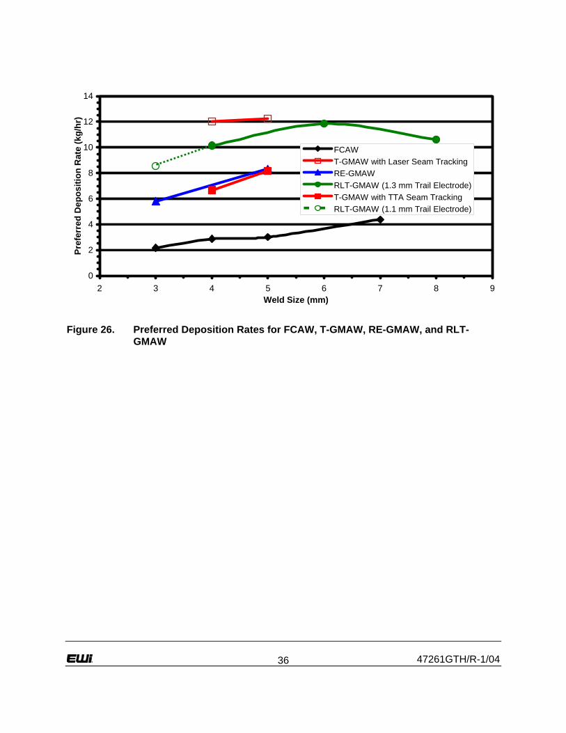
6.0 Discussion Preferred parameters for RE-GMAW for 3- and 5-mm fillet welds and RLT-GMAW for 3-, 4-, 6-, and 8-mm fillet welds are summarized in Table 2. The R factor was normalized between data developed here and prior art which had slightly smaller R factors to permit proper benchmarking analysis. The R factor was developed to ensure a proper amount of deposition R and weld volume when encountering T-joint gaps up to 1 mm. Table 2 also includes the TDR:LDR ratio that was established for the RLT-GMAW process. The TDR:LDR ratio was an important parameter for using two different electrode diameters in tandem process development. By establishing the trend based on fillet weld size, it ensured proper seam tracking with the lead electrode for a matrix of travel speeds. However, it was believed that even higher productivity can be achieved with other TDR:LDR ratios, torch setups and electrode combinations depending on the fillet size range targeted for production. Figure 25 shows a plot comparing the preferred travel speeds for FCAW, T-GMAW, RE-GMAW, and RLT-GMAW based on preferred parameters developed here and in prior investigations.(3,4,6) Figure 26 shows corresponding deposition rates for each process. In most cases, RLT-GMAW had at least twice the deposition rate as FCAW. The dashed line indicates the possibilities when using the 1.1/1.1-mm diameter electrode combination with the RLT-GMAW process for small fillet welds. Also note that for RLT-GMAW, deposition rate dropped off as the weld size was increased to 8 mm. This investigation compared an electrode combination and group of setup parameters that were fixed to optimize the productivity for a 3- to 8-mm fillet weld size range. Further changes could be made to the setup parameters, such as torch offset distance, lead electrode rotation diameter, and/or electrode size in order to obtain higher deposition rates for larger fillet welds. There were two trends displayed for T-GMAW in Figures 25 and 26. The hollow square points represented the travel speed and deposition rate potential based on prior data(1) with T-GMAW using a laser seam tracker. However, laser seam tracking does not account for electrode cast variation which was shown to be a key noise variable on small fillet welds. The solid square points represented the 1 m/min travel speed limitation for T-GMAW with TTA seam tracking by weaving. Considering the TTA seam tracking travel speed and weld size limitations of T-GMAW, RLT-GMAW had the highest travel speeds of the four processes and was agile enough to be able to weld the full array of fillet weld sizes required for panel stiffeners.

47261GTH/R-1/04 20
RLT-GMAW was designed to combine the advantages of two robust and agile processes. While obtaining deposition rates comparable to T-GMAW, the process was able to seam track at any speed via the TTA Spin Arc sensor system. RLT-GMAW was an agile process capable of making the full range of weld sizes required for shipyard panel production. Plus, process robustness was evident by the size of the weld bead shape maps for each fillet weld size. Increased travel speed was achieved while at the same time offering first-time weld quality. The economic analysis performed shows the potential to make up to 4.7 panels per shift with the RLT-GMAW process on a standard 15.2-m panel. This estimate was a 175% increase in productivity over FCAW. This increase was a conservative estimate considering the rework costs due to leg size variation that could be associated with making 3-mm fillet welds with FCAW. First-time weld quality combined with reduced panel distortion will lead to higher productivity through reduced rework and improved downstream processes. This will be an important factor when considering rework costs associated with the existing processes. These factors make RLT-GMAW a sound choice for precision fillet welding as required for new ship designs.
7.0 Conclusions 1. RE-GMAW allows accurate seam tracking at travel speeds up to 2.5 m/min and at fillet weld
sizes as small as 3 mm. 2. The TTA Spin Arc sensor was the most tolerant to electrode cast as 3-mm fillet welds were
made at 25-mm CTWD. 3. The RLT-GMAW process offers the best combination of productivity and seam tracking
robustness for agile stiffener fillet welding of complex ship panels. 4. Economic analysis showed that the RLT-GMAW process can offer up to 175% increase in
productivity over FCAW. 5. Higher productivity is possible with the RLT-GMAW process by optimizing the torch setup,
electrode conditions, and parameters for the targeted weld size range.

47261GTH/R-1/04 21
8.0 References 1. Huang, T. D., DeCan, L., Dong, P., Harwig, D. D., and Kumar, R., “Fabrication and
Engineering Technology for Lightweight Ship Structures – Part 1 – Distortion and Residual Stresses in Panel Fabrication”, Journal of Ship Production, Vol. 20, No. 1, Feb. 2004.
2. Huang, T. D., Harwig, D. D., DeCan, L., and Dong, P., “Fabrication and Engineering
Technology for Lightweight Ship Structures – Part 2 – Manufacturing Plan Development, SNAME, being peer reviewed by Journal of Ship Production”.
3. Harwig, D. D., Dierksheide, J. E., Evans, N. J., and Huang, T. D., “Precision Fillet Welding
for Lightweight Ship Structures“, Ship Tech 2004 Conference, Biloxi, MS, Jan. 27-28, 2004. 4. Dierksheide, J. E., "An Assessment of Existing and Alternative Stiffener Welding Processes"
- Thesis - The Ohio State University, Columbus, OH, June 2004. 5. Huang, T. D., DeCan, L., Dong, P., Harwig, D. D., and Kumar, R., “Shipboard Application of
Lightweight Structures – Phase 1”, Gulf Coast Regional Maritime Technology Center, Report No. 327-02-5137, May 31, 2003.
6. Harwig, D. D., “A Wise Method for Assessing Arc Welding Performance and Quality”,
Welding Journal, Vol. 79 No. 12, Dec. 2000.

47261GTH/R-1/04 22
Table 1. Economic Analysis Results
Process Weld Size
Preferred Travel Speed
(m/min) Minutes per
Stiffener
Total Time to Weld One 15.2 m Panel
(min) Panels Per
Shift FCAW 3 1.0 15 162 2.7 FCAW 4 0.8 19 192 2.3 FCAW 5 0.5 30 283 1.5
T-GMAW 4 1.8 8 108 4.0 T-GMAW 5 1.5 10 121 3.6
T-GMAW(a) 4 1.0 15 162 2.7 T-GMAW(a) 5 1.0 15 162 2.7 RE-GMAW 3 1.5 10 121 3.6 RE-GMAW 5 1.0 15 162 2.7
RLT-GMAW(b) 3 2.3 7 93 4.7 RLT-GMAW 4 1.5 10 121 3.6 RLT-GMAW 6 1.3 12 134 3.2 RLT-GMAW 8 0.6 25 243 1.8
(a) With TTA seam tracking by weaving (b) With 1.1-mm diameter trail electrode
Table 2. Preferred Process Parameters for RE- and RLT-GMAW
Welding Process
Fillet Weld Size
(mm)Reinforcement
Factor
Deposit Area
(mm2)
Preferred Travel Speed
(m/min)
Lead Electrode Diameter
(mm)
Lead Arc Length (mm)
Lead WFS
(m/min)
Trail Electrode Diameter
(mm)
Trail Arc Length (mm)
Trail WFS
(m/min)TDR:LDR
Ratio
Deposition Rate
(kg/hr)
Heat Input
(J/mm)RE-GMAW 3 2.2 5.8 1.3 1.1 1 12.0 - - - - 5.8 257RE-GMAW 5 1.4 8.3 1.0 1.1 2 17.2 - - - - 8.3 553
RLT-GMAW 3 2.2 10.5 2.3 1.1 1 13.6 1.1 1 8.2 0.6 10.5 322RLT-GMAW 4 1.8 10.1 1.5 1.1 2 9.5 1.3 2 8.6 1.2 10.1 522RLT-GMAW 6 1.1 11.8 1.3 1.1 2 10.0 1.3 2 10.8 1.4 11.8 589RLT-GMAW 8 1.1 10.6 0.6 1.1 2 7.2 1.3 2 11.1 2.1 10.6 1167

47261GTH/R-1/04 23
Figure 1. Setup for Double-Sided FCAW Tests with Mechanical Seam Tracking
1.8 m/min(70 in/min)
1.5 m/min(60 in/min)
1.3 m/min(50 in/min)
1.2 m/min(45 in/min)
1.0 m/min(40 in/min)
0.9 m/min(35 in/min)
1 mmArc Length
1.8 m/min(70 in/min)
1.5 m/min(60 in/min)
1.3 m/min(50 in/min)
1.2 m/min(45 in/min)
1.0 m/min(40 in/min)
0.9 m/min(35 in/min)
1 mmArc Length
Figure 2. 3-mm Bead Shape Map Obtained with FCAW (Preferred travel speed is shaded.)

47261GTH/R-1/04 24
0.5 m/min(20 in/min)
0.6 m/min(25 in/min)
2 mm Arc Length
1.2 m/min(45 in/min)
1.0 m/min(40 in/min)
0.9 m/min(35 in/min)
0.8 m/min(30 in/min)
1 mm Arc Length
0.5 m/min(20 in/min)
0.6 m/min(25 in/min)
2 mm Arc Length
1.2 m/min(45 in/min)
1.0 m/min(40 in/min)
0.9 m/min(35 in/min)
0.8 m/min(30 in/min)
1 mm Arc Length
Figure 3. 4-mm Bead Shape Map Obtained with FCAW (Preferred travel speed is shaded.)
0.3 m/min(10 in/min)
0.4 m/min(15 in/min)
0.9 m/min(35 in/min)
0.8 m/min(30 in/min)
0.6 m/min(25 in/min)
0.5 m/min(20 in/min)
1 mm Arc Length
3 mm Arc Length
0.3 m/min(10 in/min)
0.4 m/min(15 in/min)
0.9 m/min(35 in/min)
0.8 m/min(30 in/min)
0.6 m/min(25 in/min)
0.5 m/min(20 in/min)
1 mm Arc Length
3 mm Arc Length
Figure 4. 5-mm Bead Shape Map Obtained with FCAW (Preferred travel speed is shaded.)

47261GTH/R-1/04 25
Figure 5. Recommended CTWD Trend Based on Fillet Weld Size for FCAW to Control Wire Cast Effects
Figure 6. T-GMAW Torch (Note the close proximity of the electrodes.)

47261GTH/R-1/04 26
Figure 7. Plasma Jet-Induced Defect Characteristic of High-Speed Single Electrode GMAW
1.8 m/min(70 in/min)
2.0 m/min(80 in/min)
2.3 m/min(90 in/min)
1.5 m/min(60 in/min)
1.3 m/min(50 in/min)
1.0 m/min(40 in/min)
1 mm Arc Length
2 mm Arc Length
1.8 m/min(70 in/min)
2.0 m/min(80 in/min)
2.3 m/min(90 in/min)
1.5 m/min(60 in/min)
1.3 m/min(50 in/min)
1.0 m/min(40 in/min)
1 mm Arc Length
2 mm Arc Length
Figure 8. 4-mm Bead Shape Map Obtained with T-GMAW (Preferred travel speed is shaded.)

47261GTH/R-1/04 27
2.0 m/min(80 in/min)
1.8 m/min(70 in/min)
1.5 m/min(60 in/min)
1.3 m/min(50 in/min)
1.0 m/min(40 in/min)
0.8 m/min(30 in/min)
1 mm Arc Length
3 mm Arc Length
2.0 m/min(80 in/min)
1.8 m/min(70 in/min)
1.5 m/min(60 in/min)
1.3 m/min(50 in/min)
1.0 m/min(40 in/min)
0.8 m/min(30 in/min)
1 mm Arc Length
3 mm Arc Length
Figure 9. 5-mm Bead Shape Map Obtained with T-GMAW (Preferred travel speed is shaded.)
Figure 10. RE-GMAW Torch and Servo-Motor Unit

47261GTH/R-1/04 28
Figure 11. Schematic of RE-GMAW
Figure 12. Current Waveforms of RE-GMAW (Solid line indicates off track, dotted line indicates on track.)

47261GTH/R-1/04 29
Figure 13. Panasonic VR-006 6-Axis Robot
Figure 14. Panasonic HM-350 Pulse GMAW Power Supply

47261GTH/R-1/04 30
Figure 15. RLT-GMAW Torch Configuration (RE-GMAW torch is on the right.)
Figure 16. RLT-GMAW Torch Bracket Design
47261GTH/R-1/04 31
1.8 m/min(70 in/min)
1.5 m/min(60 in/min)
1.3 m/min(50 in/min)
1.0 m/min(40 in/min)
0.8 m/min(30 in/min)
0.5 m/min(20 in/min)
1 mm Arc Length
3 mm Arc Length
1.8 m/min(70 in/min)
1.5 m/min(60 in/min)
1.3 m/min(50 in/min)
1.0 m/min(40 in/min)
0.8 m/min(30 in/min)
0.5 m/min(20 in/min)
1 mm Arc Length
3 mm Arc Length
Figure 17. RE-GMAW Bead Shape Map for 3-mm Fillet Welds (Preferred travel speed is shaded.)
1.3 m/min(50 in/min)
1.0 m/min(40 in/min)
0.8 m/min(30 in/min)
0.5 m/min(20 in/min)
1 mm Arc Length
3 mm Arc Length
1.3 m/min(50 in/min)
1.0 m/min(40 in/min)
0.8 m/min(30 in/min)
0.5 m/min(20 in/min)
1 mm Arc Length
3 mm Arc Length
Figure 18. RE-GMAW Bead Shape Map for 5-mm Fillet Welds (Preferred travel speed is shaded.)

47261GTH/R-1/04 32
2.5 m/min(100 in/min)
2.0 m/min(80 in/min)
1.5 m/min(60 in/min)
1.0 m/min(40 in/min)
1 mm Arc Length
3 mm Arc Length
2.5 m/min(100 in/min)
2.0 m/min(80 in/min)
1.5 m/min(60 in/min)
1.0 m/min(40 in/min)
1 mm Arc Length
3 mm Arc Length
Figure 19. RLT-GMAW Bead Shape Map for 3-mm Fillet Welds (No preferred travel speed was selected for this bead shape map.)
1.8 m/min(70 in/min)
2.0 m/min(80 in/min)
1.5 m/min(60 in/min)
1.3 m/min(50 in/min)
1.0 m/min(40 in/min)
0.8 m/min(30 in/min)
1 mm Arc Length
3 mm Arc Length
1.8 m/min(70 in/min)
2.0 m/min(80 in/min)
1.5 m/min(60 in/min)
1.3 m/min(50 in/min)
1.0 m/min(40 in/min)
0.8 m/min(30 in/min)
1 mm Arc Length
3 mm Arc Length
Figure 20. RLT-GMAW Bead Shape Map for 4-mm Fillet Welds (Preferred travel speed is shaded.)

47261GTH/R-1/04 33
1.5 m/min(60 in/min)
1.3 m/min(50 in/min)
1.0 m/min(40 in/min)
0.8 m/min(30 in/min)
1 mm Arc Length
3 mm Arc Length
1.5 m/min(60 in/min)
1.3 m/min(50 in/min)
1.0 m/min(40 in/min)
0.8 m/min(30 in/min)
1 mm Arc Length
3 mm Arc Length
Figure 21. RLT-GMAW Bead Shape Map for 6-mm Fillet Welds (Preferred travel speed is shaded.)
0.8 m/min(30 in/min)
0.6 m/min(25 in/min)
0.5 m/min(20 in/min)
0.4 m/min(15 in/min)
1 mm Arc Length
2 mm Arc Length
0.8 m/min(30 in/min)
0.6 m/min(25 in/min)
0.5 m/min(20 in/min)
0.4 m/min(15 in/min)
1 mm Arc Length
2 mm Arc Length
Figure 22. RLT-GMAW Bead Shape Map for 8-mm Fillet Welds (Preferred travel speed is shaded.)

47261GTH/R-1/04 34
Figure 23. Cross Section of a 3-mm Fillet Weld Developed with 1.1/1.1-mm Diameter Electrode Combination using RLT-GMAW

47261GTH/R-1/04 35
0.0
0.5
1.0
1.5
2.0
2.5
3.0
3.5
4.0
4.5
5.0
2 3 4 5 6 7 8 9Fillet Weld Size
Num
ber o
f Pan
els
Per S
hift
FCAWT-GMAW (Laser Seam Tracking)T-GMAW (TTA Seam Tracking)RE-GMAWRLT-GMAWRLT-GMAW (1.1 mm Trail Electrode)
Figure 24. Economic Analysis Results Comparing Number of Panels for Various Fillet Welding Processes
0.0
0.5
1.0
1.5
2.0
2.5
2.5 3.5 4.5 5.5 6.5 7.5 8.5Weld Size (mm)
Pref
erre
d Tr
avel
Spe
ed (m
/min
)
FCAWT-GMAW with Laser Seam TrackingRE-GMAWRLT-GMAW (1.3 mm Trail Electrode)T-GMAW with TTA Seam TrackingRLT-GMAW (1.1 mm Trail Electrode)
Figure 25. Preferred Travel Speeds for FCAW, T-GMAW, RE-GMAW, and RLT-GMAW
47261GTH/R-1/04 36
0
2
4
6
8
10
12
14
2 3 4 5 6 7 8 9Weld Size (mm)
Pref
erre
d D
epos
ition
Rat
e (k
g/hr
)
FCAWT-GMAW with Laser Seam TrackingRE-GMAWRLT-GMAW (1.3 mm Trail Electrode)T-GMAW with TTA Seam TrackingRLT-GMAW (1.1 mm Trail Electrode)
Figure 26. Preferred Deposition Rates for FCAW, T-GMAW, RE-GMAW, and RLT-GMAW

47261GTH/R-1/04
Appendix A
ARCWISE™ Data and Charts

47261GTH/R-1/04 A-1
Table A-1. RE-GMAW Parameters used for ARCWISE™ Development
Weld Size (mm)
Deposit Area
(mm2)
Travel Speed
(m/min)
Electrode Diameter
(mm)
Arc Length (mm)
WFS (m/min)
Average Current
(A)
Average Voltage
(V)
Deposition Rate
(kg/hr) Heat Input
(J/mm) 3 4.5 0.5 1.1 1 2.5 156 21.35 0.96 393 3 4.5 0.8 1.1 1 3.7 202 22.62 1.44 360 3 4.5 1.0 1.1 1 5.0 230 24.48 1.91 333 3 4.5 1.3 1.1 1 6.2 245 26.56 2.39 307 3 4.5 1.5 1.1 1 7.4 279 28.54 2.87 313 3 4.5 1.8 1.1 1 8.7 309 31.75 3.35 331 3 4.5 0.5 1.1 3 2.5 154 23.64 0.96 430 3 4.5 0.8 1.1 3 3.7 201 26.37 1.44 417 3 4.5 1.0 1.1 3 5.0 226 26.94 1.91 360 3 4.5 1.3 1.1 3 6.2 248 27.83 2.39 326 3 4.5 1.5 1.1 3 7.4 274 28.89 2.87 312 3 4.5 1.8 1.1 3 8.7 309 31.91 3.35 333 5 12.5 0.3 1.1 1 3.4 118 19.59 1.33 546 5 12.5 0.5 1.1 1 6.9 193 22.64 2.66 516 5 12.5 0.8 1.1 1 10.3 272 28.27 3.99 605 5 12.5 1.0 1.1 1 13.8 339 32.51 5.32 651 5 12.5 1.3 1.1 1 17.2 422 33.97 6.65 677 5 12.5 0.5 1.1 3 6.9 192 25.64 2.66 581 5 12.5 0.8 1.1 3 10.3 270 30.94 3.99 658 5 12.5 1.0 1.1 3 13.8 331 34.64 5.32 677 5 12.5 1.3 1.1 3 17.2 425 35.13 6.65 705

Table A-2. RLT-GMAW Parameters used for ARCWISE™ Development
Weld Size (mm)
Weld Area
(mm2)
Travel Speed
(m/min)
Lead Electrode Diameter
(mm)
Lead Arc
Length (mm)
Lead Average
WFS (m/min)
Lead Average Current
(A)
Lead Average Voltage
(V)
Trail Electrode Diameter
(mm)
Trail Arc
Length (mm)
Trail Average
WFS (m/min)
Trail Average Current
(A)
Trail Average Voltage
(V)
Total Heat Input
(J/mm)
Total Deposition
Rate (kg/hr)
3 4.5 1.0 1.1 1 5.86 164.64 18.67 1.3 1 3.42 147.00 17.96 337 4.03
3 4.5 1.5 1.1 1 8.61 206.38 18.84 1.3 1 4.68 170.49 18.88 280 5.743 4.5 2.0 1.1 1 9.95 235.22 20.03 1.3 1 6.52 218.16 20.60 272 7.213 4.5 2.5 1.1 1 12.31 276.78 22.24 1.3 1 9.22 272.36 21.40 283 9.513 4.5 1.0 1.1 3 5.88 163.30 20.98 1.3 3 3.51 143.63 20.27 374 4.083 4.5 1.5 1.1 3 8.60 207.25 22.43 1.3 3 4.59 166.18 21.82 326 5.693 4.5 2.0 1.1 3 9.92 236.19 23.05 1.3 3 6.24 214.30 22.48 303 7.05
3 4.5 2.5 1.1 3 12.31 276.11 24.79 1.3 3 9.34 268.49 25.18 321 9.57
4 8.0 0.8 1.1 1 6.57 159.65 18.79 1.3 1 4.54 165.64 18.43 477 4.88
4 8.0 1.0 1.1 1 8.59 186.10 19.75 1.3 1 5.87 188.94 18.94 428 6.354 8.0 1.3 1.1 1 9.84 214.46 20.11 1.3 1 8.52 245.67 20.17 438 8.204 8.0 1.5 1.1 1 11.20 243.94 22.59 1.3 1 9.95 271.94 23.79 472 9.464 8.0 1.8 1.1 1 14.01 278.29 24.69 1.3 1 11.39 283.76 26.42 485 11.294 8.0 2.0 1.1 1 16.44 306.74 26.05 1.3 1 14.87 327.56 28.07 507 14.034 8.0 0.8 1.1 3 6.58 159.04 21.97 1.3 3 4.54 160.82 22.67 562 4.894 8.0 1.0 1.1 3 8.61 187.74 24.00 1.3 3 5.87 183.82 23.75 524 6.364 8.0 1.3 1.1 3 9.87 216.05 25.07 1.3 3 8.24 226.40 24.89 522 8.074 8.0 1.5 1.1 3 11.24 244.28 26.48 1.3 3 9.95 266.30 27.99 548 9.474 8.0 1.8 1.1 3 14.00 276.86 27.80 1.3 3 11.49 277.66 28.91 531 11.34
4 8.0 2.0 1.1 3 16.47 305.61 28.66 1.3 3 14.79 321.18 30.93 552 13.99
47261GTH/R-1/04 A-2

Table A-2. (Cont.)
Weld Size (mm)
Weld Area
(mm2)
Travel Speed
(m/min)
Lead Electrode Diameter
(mm)
Lead Arc
Length (mm)
Lead Average
WFS (m/min)
Lead Average Current
(A)
Lead Average Voltage
(V)
Trail Electrode Diameter
(mm)
Trail Arc
Length (mm)
Trail Average
WFS (m/min)
Trail Average Current
(A)
Trail Average Voltage
(V)
Total Heat Input
(J/mm)
Total Deposition
Rate (kg/hr)
6 18.0 0.8 1.1 1 7.32 171.54 18.61 1.3 1 6.23 198.49 18.62 542 6.046 18.0 1.0 1.1 1 8.77 196.94 19.18 1.3 1 8.90 251.57 21.55 543 7.986 18.0 1.3 1.1 1 9.98 223.27 20.44 1.3 1 10.27 280.20 21.45 500 9.156 18.0 1.5 1.1 1 11.43 251.77 22.12 1.3 1 11.94 308.79 21.24 477 10.576 18.0 0.8 1.1 3 7.34 169.79 22.18 1.3 3 6.20 194.35 22.80 645 6.036 18.0 1.0 1.1 3 8.77 195.52 22.75 1.3 3 8.58 236.75 24.78 609 7.816 18.0 1.3 1.1 3 9.99 224.84 24.01 1.3 3 10.24 269.25 26.17 588 9.146 18.0 1.5 1.1 3 11.46 253.68 25.59 1.3 3 12.02 307.96 28.55 602 10.63
8 32.0 0.4 1.1 1 4.60 118.58 26.21 1.3 1 7.34 227.70 21.50 1260 5.56
8 32.0 0.5 1.1 1 7.17 168.40 20.58 1.3 1 9.61 259.49 22.09 1086 7.738 32.0 0.6 1.1 1 7.64 176.35 21.31 1.3 1 11.33 292.25 23.70 1010 8.808 32.0 0.8 1.1 1 8.66 184.68 19.57 1.3 1 15.92 346.63 29.73 1096 11.568 32.0 0.4 1.1 3 4.41 117.36 21.43 1.3 3 6.94 221.60 24.75 1260 5.288 32.0 0.5 1.1 2 7.60 165.87 20.10 1.3 3 9.59 268.26 28.26 1289 7.888 32.0 0.6 1.1 2 7.77 177.42 21.87 1.3 3 11.21 297.38 28.49 1167 8.798 32.0 0.8 1.1 2 8.15 184.45 20.86 1.3 3 16.12 346.63 32.66 1194 11.46
47261GTH/R-1/04 A-3

47261GTH/R-1/04 A-4
0
5
10
15
20
25
30
35
40
90 140 190 240 290 340 390 440 490Average Current (A)
Ave
rage
Vol
tage
(V)
1 mm Arc Length3 mm Arc Length
Figure A-1. Voltage Versus Current for 3-mm Fillet Welds with RE-GMAW (Shaded area represents the operating window.)
0
5
10
15
20
25
30
35
40
0 2 4 6 8 10 12 14 16 18 2WFS (m/min)
Ave
rage
Vol
tage
(V)
0
1 mm Arc Length3 mm Arc Length
Figure A-2. Voltage Versus WFS for 3-mm Fillet Welds with RE-GMAW (Shaded area represents the operating window.)

47261GTH/R-1/04 A-5
90
140
190
240
290
340
390
440
490
0 2 4 6 8 10 12 14 16 18 2WFS (m/min)
Aver
age
Cur
rent
(A)
0
1 mm Arc Length3 mm Arc Length
Figure A-3. Current Versus WFS for 3-mm Fillet Welds with RE-GMAW (Shaded area represents the operating window.)
50
250
450
650
850
1050
1250
1450
1650
0 1 2 3 4 5 6 7 8 9 10 11 12 13 14 15Deposition Rate (kg/hr)
Hea
t Inp
ut (J
/mm
)
1 mm Arc Length3 mm Arc Length
Figure A-4. Heat Input Versus Deposition Rate for 3-mm Fillet Welds with RE-GMAW (Shaded area represents the operating window.)

47261GTH/R-1/04 A-6
0
5
10
15
20
25
30
35
40
90 140 190 240 290 340 390 440 490Average Current (A)
Ave
rage
Vol
tage
(V)
1 mm Arc Length3 mm Arc Length
Figure A-5. Voltage Versus Current for 5-mm Fillet Welds with RE-GMAW (Shaded area represents the operating window.)
0
5
10
15
20
25
30
35
40
0 2 4 6 8 10 12 14 16 18 20WFS (m/min)
Ave
rage
Vol
tage
(V)
1 mm Arc Length3 mm Arc Length
Figure A-6. Voltage Versus WFS for 5-mm Fillet Welds with RE-GMAW (Shaded area represents the operating window.)

47261GTH/R-1/04 A-7
90
140
190
240
290
340
390
440
490
0 2 4 6 8 10 12 14 16 18 2WFS (m/min)
Ave
rage
Cur
rent
(A)
0
1 mm Arc Length3 mm Arc Length
Figure A-7. Current Versus WFS for 5-mm Fillet Welds with RE-GMAW (Shaded area represents the operating window.)
50
250
450
650
850
1050
1250
1450
1650
0 1 2 3 4 5 6 7 8 9 10 11 12 13 14 15Deposition Rate (kg/hr)
Hea
t Inp
ut (J
/mm
)
1 mm Arc Length3 mm Arc Length
Figure A-8. Heat Input Versus Deposition Rate for 5-mm Fillet Welds with RE-GMAW (Shaded area represents the operating window.)

47261GTH/R-1/04 A-8
15
20
25
30
35
40
90 140 190 240 290 340 390 440 490Average Current (A)
Ave
rage
Vol
tage
(V)
1 mm Arc Length3 mm Arc Length
Figure A-9. Lead Arc Voltage Versus Current for 3-mm Fillet Welds with RLT-GMAW (Shaded area represents the operating window.)
15
20
25
30
35
40
0 2 4 6 8 10 12 14 16 18 2WFS (m/min)
Ave
rage
Vol
tage
(V)
0
1 mm Arc Length3 mm Arc Length
Figure A-10. Lead Arc Voltage Versus WFS for 3-mm Fillet Welds with RLT-GMAW (Shaded area represents the operating window.)

47261GTH/R-1/04 A-9
90
140
190
240
290
340
390
440
490
0 2 4 6 8 10 12 14 16 18WFS (m/min)
Ave
rage
Cur
rent
(A)
20
1 mm Arc Length3 mm Arc Length
Figure A-11. Lead Arc Current Versus WFS for 3-mm Fillet Welds with RLT-GMAW (Shaded area represents the operating window.)
15
20
25
30
35
40
90 140 190 240 290 340 390 440 490Average Current (A)
Ave
rage
Vol
tage
(V)
1 mm Arc Length3 mm Arc Length
Figure A-12. Trail Arc Voltage Versus Current for 3-mm Fillet Welds with RLT-GMAW (Shaded area represents the operating window.)

47261GTH/R-1/04 A-10
15
20
25
30
35
40
0 2 4 6 8 10 12 14 16 18 2WFS (m/min)
Ave
rage
Vol
tage
(V)
0
1 mm Arc Length3 mm Arc Length
Figure A-13. Trail Arc Voltage Versus WFS for 3-mm Fillet Welds with RLT-GMAW (Shaded area represents the operating window.)
90
140
190
240
290
340
390
440
490
0 2 4 6 8 10 12 14 16 18WFS (m/min)
Ave
rage
Cur
rent
(A)
20
1 mm Arc Length3 mm Arc Length
Figure A-14. Trail Arc Current Versus WFS for 3-mm Fillet Welds with RLT-GMAW (Shaded area represents the operating window.)

47261GTH/R-1/04 A-11
50
250
450
650
850
1050
1250
1450
1650
0 1 2 3 4 5 6 7 8 9 10 11 12 13 14 15Total Deposition Rate (kg/hr)
Tota
l Hea
t Inp
ut (J
/mm
)
1 mm Arc Length3 mm Arc Length
Figure A-15. Total Heat Input Versus Deposition Rate for 3-mm Fillet Welds with RLT-GMAW (Shaded area represents the operating window.)
15
20
25
30
35
40
90 140 190 240 290 340 390 440 490Average Current (A)
Ave
rage
Vol
tage
(V)
1 mm Arc Length3 mm Arc Length
Figure A-16. Lead Arc Voltage Versus Current for 4-mm Fillet Welds with RLT-GMAW (Shaded area represents the operating window.)

47261GTH/R-1/04 A-12
15
20
25
30
35
40
0 2 4 6 8 10 12 14 16 18 2WFS (m/min)
Ave
rage
Vol
tage
(V)
0
1 mm Arc Length3 mm Arc Length
Figure A-17. Lead Arc Voltage Versus WFS for 4-mm Fillet Welds with RLT-GMAW (Shaded area represents the operating window.)
90
140
190
240
290
340
390
440
490
0 2 4 6 8 10 12 14 16 18WFS (m/min)
Ave
rage
Cur
rent
(A)
20
1 mm Arc Length3 mm Arc Length
Figure A-18. Lead Arc Current Versus WFS for 4-mm Fillet Welds with RLT-GMAW (Shaded area represents the operating window.)

47261GTH/R-1/04 A-13
15
20
25
30
35
40
90 140 190 240 290 340 390 440 490Average Current (A)
Ave
rage
Vol
tage
(V)
1 mm Arc Length3 mm Arc Length
Figure A-19. Trail Arc Voltage Versus Current for 4-mm Fillet Welds with RLT-GMAW (Shaded area represents the operating window.)
15
20
25
30
35
40
0 2 4 6 8 10 12 14 16 18 2WFS (m/min)
Ave
rage
Vol
tage
(V)
0
1 mm Arc Length3 mm Arc Length
Figure A-20. Trail Arc Voltage Versus WFS for 4-mm Fillet Welds with RLT-GMAW (Shaded area represents the operating window.)

47261GTH/R-1/04 A-14
90
140
190
240
290
340
390
440
490
0 2 4 6 8 10 12 14 16 18WFS (m/min)
Ave
rage
Cur
rent
(A)
20
1 mm Arc Length3 mm Arc Length
Figure A-21. Trail Arc Current Versus WFS for 4-mm Fillet Welds with RLT-GMAW (Shaded area represents the operating window.)
50
250
450
650
850
1050
1250
1450
1650
0 1 2 3 4 5 6 7 8 9 10 11 12 13 14 15Total Deposition Rate (kg/hr)
Tota
l Hea
t Inp
ut (J
/mm
)
1 mm Arc Length3 mm Arc Length
Figure A-22. Total Heat Input Versus Deposition Rate for 4-mm Fillet Welds with RLT-GMAW (Shaded area represents the operating window.)

47261GTH/R-1/04 A-15
15
20
25
30
35
40
90 140 190 240 290 340 390 440 490Average Current (A)
Ave
rage
Vol
tage
(V)
1 mm Arc Length3 mm Arc Length
Figure A-23. Lead Arc Voltage Versus Current for 6-mm Fillet Welds with RLT-GMAW (Shaded area represents the operating window.)
15
20
25
30
35
40
0 2 4 6 8 10 12 14 16 18 2WFS (m/min)
Ave
rage
Vol
tage
(V)
0
1 mm Arc Length3 mm Arc Length
Figure A-24. Lead Arc Voltage Versus WFS for 6-mm Fillet Welds with RLT-GMAW (Shaded area represents the operating window.)

47261GTH/R-1/04 A-16
90
140
190
240
290
340
390
440
490
0 2 4 6 8 10 12 14 16 18WFS (m/min)
Ave
rage
Cur
rent
(A)
20
1 mm Arc Length3 mm Arc Length
Figure A-25. Lead Arc Current Versus WFS for 6-mm Fillet Welds with RLT-GMAW (Shaded area represents the operating window.)
15
20
25
30
35
40
90 140 190 240 290 340 390 440 490Average Current (A)
Ave
rage
Vol
tage
(V)
1 mm Arc Length3 mm Arc Length
Figure A-26. Trail Arc Voltage Versus Current for 6-mm Fillet Welds with RLT-GMAW (Shaded area represents the operating window.)

47261GTH/R-1/04 A-17
15
20
25
30
35
40
0 2 4 6 8 10 12 14 16 18 2WFS (m/min)
Ave
rage
Vol
tage
(V)
0
1 mm Arc Length3 mm Arc Length
Figure A-27. Trail Arc Voltage Versus WFS for 6-mm Fillet Welds with RLT-GMAW (Shaded area represents the operating window.)
90
140
190
240
290
340
390
440
490
0 2 4 6 8 10 12 14 16 18WFS (m/min)
Ave
rage
Cur
rent
(A)
20
1 mm Arc Length3 mm Arc Length
Figure A-28. Trail Current Versus WFS for 6-mm Fillet Welds with RLT-GMAW (Shaded area represents the operating window.)

47261GTH/R-1/04 A-18
50
250
450
650
850
1050
1250
1450
1650
0 1 2 3 4 5 6 7 8 9 10 11 12 13 14 15Total Deposition Rate (kg/hr)
Tota
l Hea
t Inp
ut (J
/mm
)
1 mm Arc Length3 mm Arc Length
Figure A-29. Total Heat Input Versus Deposition Rate for 6-mm Fillet Welds with RLT-GMAW (Shaded area represents the operating window.)
15
20
25
30
35
40
90 140 190 240 290 340 390 440 490Average Current (A)
Ave
rage
Vol
tage
(V)
1 mm Arc Length2 mm Arc Length
Figure A-30. Lead Arc Voltage Versus Current for 8-mm Fillet Welds with RLT-GMAW (Shaded area represents the operating window.)

47261GTH/R-1/04 A-19
15
20
25
30
35
40
0 2 4 6 8 10 12 14 16 18 2WFS (m/min)
Ave
rage
Vol
tage
(V)
0
1 mm Arc Length2 mm Arc Length
Figure A-31. Lead Arc Voltage Versus WFS for 8-mm Fillet Welds with RLT-GMAW (Shaded area represents the operating window.)
90
140
190
240
290
340
390
440
490
0 2 4 6 8 10 12 14 16 18WFS (m/min)
Ave
rage
Cur
rent
(A)
20
1 mm Arc Length2 mm Arc Length
Figure A-32. Lead Arc Current Versus WFS for 8-mm Fillet Welds with RLT-GMAW (Shaded area represents the operating window.)

47261GTH/R-1/04 A-20
15
20
25
30
35
40
90 140 190 240 290 340 390 440 490Average Current (A)
Ave
rage
Vol
tage
(V)
1 mm Arc Length3 mm Arc Length
Figure A-33. Trail Arc Voltage Versus Current for 8-mm Fillet Welds with RLT-GMAW (Shaded area represents the operating window.)
15
20
25
30
35
40
0 2 4 6 8 10 12 14 16 18 2WFS (m/min)
Ave
rage
Vol
tage
(V)
0
1 mm Arc Length3 mm Arc Length
Figure A-34. Trail Arc Voltage Versus WFS for 8-mm Fillet Welds with RLT-GMAW (Shaded area represents the operating window.)

47261GTH/R-1/04 A-21
90
140
190
240
290
340
390
440
490
0 2 4 6 8 10 12 14 16 18WFS (m/min)
Ave
rage
Cur
rent
(A)
20
1 mm Arc Length3 mm Arc Length
Figure A-35. Trail Current Versus WFS for 8-mm Fillet Welds with RLT-GMAW (Shaded area represents the operating window.)
50
250
450
650
850
1050
1250
1450
1650
0 1 2 3 4 5 6 7 8 9 10 11 12 13 14 15Total Deposition Rate (kg/hr)
Tota
l Hea
t Inp
ut (J
/mm
)
1 mm Arc Length2/3 mm Arc Length
Figure A-36. Total Heat Input Versus Deposition Rate for 8-mm Fillet Welds with RLT-GMAW (Shaded area represents the operating window.)