Tandem Pump Offshore Hydraulic Power Unit User’s...
82
Tandem Pump Offshore Hydraulic Power Unit User’s Manual Copyright © 2009 E.H. Wachs. All rights reserved. This manual may not be reproduced in whole or in part without the written consent of E.H. Wachs. E.H. Wachs 600 Knightsbridge Parkway Lincolnshire, IL 60069 www.ehwachs.com E.H. Wachs Part No. 14-MAN-12 Rev. 2-0709, July 2009 Revision History: Original October 2008 Rev. 1 November 2008
Transcript of Tandem Pump Offshore Hydraulic Power Unit User’s...

Tandem Pump OffshoreHydraulic Power Unit
User’s Manual
Copyright © 2009 E.H. Wachs. All rights reserved.This manual may not be reproduced in whole or in part
without the written consent of E.H. Wachs.
E.H. Wachs600 Knightsbridge ParkwayLincolnshire, IL 60069www.ehwachs.com
E.H. Wachs Part No. 14-MAN-12Rev. 2-0709, July 2009
Revision History:Original October 2008Rev. 1 November 2008

Tandem Pump Offshore Hydraulic Power Unit User’s Manual
Part No. 14-MAN-12, Rev. 2-0709 E.H. Wachs

Table of Contents
Table of ContentsChapter 1: About the Tandem Pump Power Unit . . . . . . . . . . . . . . . . . . . . . . . . . . . . . . . . . . . 1Purpose of This Manual . . . . . . . . . . . . . . . . . . . . . . . . . . . . . . . . . . . . . . . . . . . . . . . . . . . . . . . . . 1How to Use The Manual . . . . . . . . . . . . . . . . . . . . . . . . . . . . . . . . . . . . . . . . . . . . . . . . . . . . . . . . . 1Symbols and Warnings . . . . . . . . . . . . . . . . . . . . . . . . . . . . . . . . . . . . . . . . . . . . . . . . . . . . . . . . . . 2Manual Updates and Revision Tracking. . . . . . . . . . . . . . . . . . . . . . . . . . . . . . . . . . . . . . . . . . . . . 3Equipment Description . . . . . . . . . . . . . . . . . . . . . . . . . . . . . . . . . . . . . . . . . . . . . . . . . . . . . . . . . . 3
System Specifications . . . . . . . . . . . . . . . . . . . . . . . . . . . . . . . . . . . . . . . . . . . . . . . . . . . . . . . . 3System Components . . . . . . . . . . . . . . . . . . . . . . . . . . . . . . . . . . . . . . . . . . . . . . . . . . . . . . . . . 4
Hydraulic Fluid Overview . . . . . . . . . . . . . . . . . . . . . . . . . . . . . . . . . . . . . . . . . . . . . . . . . . . . . . . 7Specifications . . . . . . . . . . . . . . . . . . . . . . . . . . . . . . . . . . . . . . . . . . . . . . . . . . . . . . . . . . . . . . 8
Chapter 2: Safety . . . . . . . . . . . . . . . . . . . . . . . . . . . . . . . . . . . . . . . . . . . . . . . . . . . . . . . . . . . . 11Operator Safety . . . . . . . . . . . . . . . . . . . . . . . . . . . . . . . . . . . . . . . . . . . . . . . . . . . . . . . . . . . . . . . 11
Safety Symbols . . . . . . . . . . . . . . . . . . . . . . . . . . . . . . . . . . . . . . . . . . . . . . . . . . . . . . . . . . . . 12Protective Equipment Requirements . . . . . . . . . . . . . . . . . . . . . . . . . . . . . . . . . . . . . . . . . . . 13Safety Procedures . . . . . . . . . . . . . . . . . . . . . . . . . . . . . . . . . . . . . . . . . . . . . . . . . . . . . . . . . . 13
Safety Labels. . . . . . . . . . . . . . . . . . . . . . . . . . . . . . . . . . . . . . . . . . . . . . . . . . . . . . . . . . . . . . . . . 15
Chapter 3: Operating Instructions . . . . . . . . . . . . . . . . . . . . . . . . . . . . . . . . . . . . . . . . . . . . . . 17Setting Up the Power Unit . . . . . . . . . . . . . . . . . . . . . . . . . . . . . . . . . . . . . . . . . . . . . . . . . . . . . . 17Start-Up and Operation . . . . . . . . . . . . . . . . . . . . . . . . . . . . . . . . . . . . . . . . . . . . . . . . . . . . . . . . . 23
Engine Starting Tips . . . . . . . . . . . . . . . . . . . . . . . . . . . . . . . . . . . . . . . . . . . . . . . . . . . . . . . . 25Operating Checks . . . . . . . . . . . . . . . . . . . . . . . . . . . . . . . . . . . . . . . . . . . . . . . . . . . . . . . . . . 26Two-Circuit Mode Operation . . . . . . . . . . . . . . . . . . . . . . . . . . . . . . . . . . . . . . . . . . . . . . . . . 26Combined-Circuit Mode Operation . . . . . . . . . . . . . . . . . . . . . . . . . . . . . . . . . . . . . . . . . . . . 32
Chapter 4: Maintenance. . . . . . . . . . . . . . . . . . . . . . . . . . . . . . . . . . . . . . . . . . . . . . . . . . . . . . . 37Disabling the Starter for Service. . . . . . . . . . . . . . . . . . . . . . . . . . . . . . . . . . . . . . . . . . . . . . . . . . 37Hydraulic System . . . . . . . . . . . . . . . . . . . . . . . . . . . . . . . . . . . . . . . . . . . . . . . . . . . . . . . . . . . . . 39
Cooler . . . . . . . . . . . . . . . . . . . . . . . . . . . . . . . . . . . . . . . . . . . . . . . . . . . . . . . . . . . . . . . . . . . 43Engine Maintenance and Service . . . . . . . . . . . . . . . . . . . . . . . . . . . . . . . . . . . . . . . . . . . . . . . . . 43
Fluid Levels . . . . . . . . . . . . . . . . . . . . . . . . . . . . . . . . . . . . . . . . . . . . . . . . . . . . . . . . . . . . . . 45Air Filters . . . . . . . . . . . . . . . . . . . . . . . . . . . . . . . . . . . . . . . . . . . . . . . . . . . . . . . . . . . . . . . . 45Spark Arrestor. . . . . . . . . . . . . . . . . . . . . . . . . . . . . . . . . . . . . . . . . . . . . . . . . . . . . . . . . . . . . 47
Air Starter System. . . . . . . . . . . . . . . . . . . . . . . . . . . . . . . . . . . . . . . . . . . . . . . . . . . . . . . . . . . . . 47Starter Motor Oiler . . . . . . . . . . . . . . . . . . . . . . . . . . . . . . . . . . . . . . . . . . . . . . . . . . . . . . . . . 48
Checking for Leaks . . . . . . . . . . . . . . . . . . . . . . . . . . . . . . . . . . . . . . . . . . . . . . . . . . . . . . . . . . . . 49Troubleshooting . . . . . . . . . . . . . . . . . . . . . . . . . . . . . . . . . . . . . . . . . . . . . . . . . . . . . . . . . . . . . . 49
Engine . . . . . . . . . . . . . . . . . . . . . . . . . . . . . . . . . . . . . . . . . . . . . . . . . . . . . . . . . . . . . . . . . . . 49Hydraulic System . . . . . . . . . . . . . . . . . . . . . . . . . . . . . . . . . . . . . . . . . . . . . . . . . . . . . . . . . . 52
E.H. Wachs Part No. 14-MAN-12, Rev. 2-0709 i

Tandem Pump Offshore Hydraulic Power Unit User’s Manual
Chapter 5: Parts List and Ordering Information . . . . . . . . . . . . . . . . . . . . . . . . . . . . . . . . . . 55Ordering Information . . . . . . . . . . . . . . . . . . . . . . . . . . . . . . . . . . . . . . . . . . . . . . . . . . . . . . . . . . 55
Ordering Replacement Parts . . . . . . . . . . . . . . . . . . . . . . . . . . . . . . . . . . . . . . . . . . . . . . . . . . 55Repair Information . . . . . . . . . . . . . . . . . . . . . . . . . . . . . . . . . . . . . . . . . . . . . . . . . . . . . . . . . 55Warranty Information . . . . . . . . . . . . . . . . . . . . . . . . . . . . . . . . . . . . . . . . . . . . . . . . . . . . . . . 56Return Goods Address . . . . . . . . . . . . . . . . . . . . . . . . . . . . . . . . . . . . . . . . . . . . . . . . . . . . . . 56
Drawings and Parts Lists . . . . . . . . . . . . . . . . . . . . . . . . . . . . . . . . . . . . . . . . . . . . . . . . . . . . . . . 56
ii Part No. 14-MAN-12, Rev. 2-0709 E.H. Wachs

Chapter 1, About the Tandem Pump Power Unit
Chapter 1
About the Tandem Pump Power Unit
PURPOSE OF THIS MANUAL
This manual explains how to operate and maintain the tan-dem pump hydraulic power unit. It includes instructions for set-up, operation, and maintenance. It also contains parts lists and diagrams to help you order replacement parts and perform user-serviceable repairs.
HOW TO USE THE MANUAL
Throughout this manual, refer to this column for warnings, cautions, and notices with supplementary information.
This manual is organized to help you quickly find the infor-mation you need. Each chapter describes a specific topic on using or maintaining the equipment.
Each page is designed with two columns. This large column on the inside of the page contains instructions and illustra-tions. Use these instructions to operate and maintain the equipment.
The narrower column on the outside contains additional information such as warnings, special notes, and defini-tions. Refer to it for safety notes and other information.
In This Chapter
PURPOSE OF THIS MANUAL
HOW TO USE THE MANUAL
SYMBOLS AND WARNINGS
MANUAL UPDATES AND REVISION TRACKING
EQUIPMENT DESCRIPTION
HYDRAULIC FLUID OVERVIEW
E.H. Wachs Part No. 14-MAN-12, Rev. 2-0709 1

Tandem Pump Offshore Hydraulic Power Unit User’s Manual
SYMBOLS AND WARNINGS
The following symbols are used throughout this manual to indicate special notes and warnings. They appear in the out-side column of the page, next to the section they refer to. Make sure you understand what each symbol means, and follow all instructions for cautions and warnings.
A WARNING alert with the safety alert symbol indicates a potentially hazardous situa-tion that could result in seri-ous injury or death.
A CAUTION alert with the safety alert symbol indicates a potentially hazardous situa-tion that could result in minor or moderate injury.
A CAUTION alert with the damage alert symbol indi-cates a situation that will result in damage to the equipment.
An IMPORTANT alert with the damage alert symbol indi-cates a situation that may result in damage to the equipment.
WARNINGThis is the safety alert symbol. It is used to alert you to potential personal injury hazards. Obey all safety messages that follow this symbol to avoid possible injury or death.
CAUTION
CAUTIONThis is the equipment damage alert symbol. It is used to alert you to poten-tial equipment damage situations. Obey all messages that follow this sym-bol to avoid damaging the equipment or workpiece on which it is operating.
IMPORTANT
2 Part No. 14-MAN-12, Rev. 2-0709 E.H. Wachs

Chapter 1, About the Tandem Pump Power Unit: Manual Updates and Revision Tracking
A NOTE provides supple-mentary information or oper-ating tips.
MANUAL UPDATES AND REVISION TRACKING
Current versions of E.H. Wachs Company manuals are also available in PDF for-mat. You can request an electronic copy of this manual by emailing customer service at [email protected].
Occasionally, we will update manuals with improved opera-tion or maintenance procedures, or with corrections if nec-essary. Revised manuals will be available for customers. When a manual is revised, we will update the revision his-tory on the title page and at the bottom of the pages.
You may have factory service or upgrades performed on the equipment. If this service changes any technical data or operation and maintenance procedures, we will include a revised manual when we return the equipment to you.
EQUIPMENT DESCRIPTION
The tandem pump hydraulic power unit is designed to oper-ate with either two independent hydraulic circuits, provid-ing 8 gpm and 16 gpm flow, or with one combined circuit providing up to 24 gpm flow. A flow mode lever on the sys-tem control panel switches the unit between independent and combined flow.
System Specifications
• Dual pump providing 16 gpm (60 l/m)and 8 gpm (30 l/m) hydraulic circuits at 2200 psi (152 bar)
• Combined flow mode for up to 24 gpm (90 l/m)• Kubota V2203 diesel engine (48.1 HP @ 2800 rpm)• Air start (3/4”-14 taper pipe thread per ANSI B1.20.1)• Dry air cleaner• 16 gallon (61 liter) diesel fuel tank• ATEX-rated spark arrestor/muffler• Safety air shut-off/overspeed valve
NOTENOTEThis symbol indicates a user note. Notes provide additional information to supple-ment the instructions, or tips for easier operation.
E.H. Wachs Part No. 14-MAN-12, Rev. 2-0709 3

Tandem Pump Offshore Hydraulic Power Unit User’s Manual
• 50 gallon (189 liter) hydraulic tank• Inline flow meters—one each circuit: 30 gpm (114 l/m)
and 10 gpm (38 l/m)• 0-3000 psi (207 bar) pressure gauges—one each circuit• Steel tubular frame with drip pan• Lifting eyes at 4 corners• Approximate dimensions:
height: 60.25” (153 cm)length: 72” (183 cm)width: 40” (102 cm)
• Approximate weight: 1920 lbs (864 kg) empty; 2400 lbs (1082 kg) with fuel and hydraulic oil tanks full.
For detailed information on the diesel engine, see the Kubota engine manual.
System Components
The following figures illustrate the components of the power unit.
4 Part No. 14-MAN-12, Rev. 2-0709 E.H. Wachs

Chapter 1, About the Tandem Pump Power Unit: Equipment Description
Figure 1-1. The photo shows the front view of the HPU, with major components illustrated.
Lift eyes
Control panel
Fuel cap
Diesel engine
Lift eyes
Hydraulic oil temperature and level gauge
Hydraulic oil reservoir
Hydraulic oil cooler
Exhaust pipe
Drain plug
E.H. Wachs Part No. 14-MAN-12, Rev. 2-0709 5

Tandem Pump Offshore Hydraulic Power Unit User’s Manual
Figure 1-2. The photo shows the components visible from the rear side of the HPU.
Hydraulic suction line
Diesel engine
Hydraulic connectors
Hydraulic reservoir fill cap
Hydraulic oil cooler
Engine radiator
Engine air filter
Diesel fuel tank
Air starter connection
Hydraulic oil drain valve
Hydraulic oil temperature and level gauge
6 Part No. 14-MAN-12, Rev. 2-0709 E.H. Wachs

Chapter 1, About the Tandem Pump Power Unit: Hydraulic Fluid Overview
Figure 1-3. HPU control panel. When the flow mode lever is in the two-circuit position, both hydraulic cir-cuits are operating. When the lever is in combined cir-cuit position, only Circuit #2 is operating.
HYDRAULIC FLUID OVERVIEW
The performance and life expectancy of your Wachs hydraulic power unit largely depends on the hydraulic fluid used. One of the most important fluid characteristics is vis-cosity—the “thickness” of the fluid. Viscosity choice is a compromise; the fluid must be thin enough to flow easily but thick enough to seal and lubricate mating surfaces.
Instruction label
Engine oil pressure
Engine temperature
Throttle
Engine starter
Engine shut-off
Emergency shut-off
Circuit #2 hydraulic pressure
Circuit #2 hydraulic flow
Flow mode leverDown = combined circuit modeRight = two-circuit mode
Circuit #1 hydraulic pressure
Circuit #1 hydraulic flow
Circuit #1 flow control
NOTE: In combined circuit mode, the Circuit #2 gauges register the com-bined circuit pres-sure and flow.
Circuit #2 flow control
Front service panel—turn and release pins to remove the panel
E.H. Wachs Part No. 14-MAN-12, Rev. 2-0709 7

Tandem Pump Offshore Hydraulic Power Unit User’s Manual
Fluid temperature greatly affects its viscosity. As the fluid warms it gets thinner (lower viscosity) and as it cools it gets thicker (higher viscosity). Your Wachs hydraulic power unit has an optimal viscosity range which is listed in the follow-ing “Specifications” section. Ambient temperatures, operat-ing loads, and many other contributors affect the fluid’s viscosity. A hydraulic fluid for use in 0° F (-18° C) may not work adequately in 100° F (38° C).
Cleanliness of the hydraulic oil is extremely important for the life expectancy of the hydraulic components. Wachs rec-ommends the fluid used to be maintained at ISO Cleanliness Code 19/17/14 per SAE J1165. Establishing a fluid mainte-nance schedule is the best way of meeting viscosity and fluid cleanliness requirements.
Premium grade petroleum-based hydraulic fluids will pro-vide the best performance for your Wachs hydraulic power unit. These fluids typically contain anti-wear additives, rust inhibitors, anti-foaming agents, and oxidation inhibitors. Premium grade fluids carry an ISO VG rating. Synthetic fluids, fluids with viscosity index improvers (ATF or multi-viscosity oil), and SAE grade oils maybe used, but their use will require more frequent maintenance intervals and appli-cation review in your system.
Specifications
NOTE: These specifications are guidelines for the hydraulic power unit only. Your hydraulic tools may require more stringent requirements. For example, your tool may limit the operating viscosity range to 85-450 SSU (16 - 95 CSt). Always consult your hydraulic tool manufacturer for hydraulic fluid guidelines.
Table 1: Viscosity Data
UnitsMinimum
Continuous Viscosity
Optimum Operating
Viscosity Range
Maximum Viscosity at
Pressure
Viscosity Range Requiring <50% Outlet Pressure
SSU 41 55-190 450 470-5000
CSt 9 16-40 95 100-1000
8 Part No. 14-MAN-12, Rev. 2-0709 E.H. Wachs

Chapter 1, About the Tandem Pump Power Unit: Hydraulic Fluid Overview
The following are recommended hydraulic fluids for typical industrial environments:
• Citgo AW (anti-wear) 32• Shell Tellus T-32• Shell Tellus S-46• Chevron AW-32
Table 2: Hydraulic Fluid Specifications
Specification Range
Pour Point -10° F (-23° C) min.
Flash Point (ASTM D-92) 340° F (171° C) min.
Emulsion Test (ASTM D-1401) 30 minutes min.
Oxidation Test (ASTM D-943) 1000 hours min.
Rust Inhibition Test (ASTM D-665 A & B) Pass - No Rust
Wear Test (ASTM D-2882) 60 mg maximum
E.H. Wachs Part No. 14-MAN-12, Rev. 2-0709 9

Tandem Pump Offshore Hydraulic Power Unit User’s Manual
10 Part No. 14-MAN-12, Rev. 2-0709 E.H. Wachs

Chapter 2, Safety
Chapter 2
Safety
The E.H. Wachs Company takes great pride in designing and manufacturing safe, high-quality products. We make user safety a top priority in the design of all our products.
Read this chapter carefully before operating the hydraulic power unit. It contains important safety instructions and recommendations.
OPERATOR SAFETY
Follow these guidelines for safe operation of the equip-ment.
Look for this sym-bol throughout the manual. It indicates a personal injury hazard.
• READ THE OPERATING MANUAL. Make sure you understand all setup and operating instructions before you begin.
• INSPECT MACHINE AND ACCESSORIES. Before starting the machine, look for loose bolts or nuts, leaking lubricant, rusted components, and any other physical conditions that may affect operation. Properly maintaining the machine can greatly decrease the chances for injury.
• ALWAYS READ PLACARDS AND LABELS. Make sure all placards, labels, and stickers are clearly legible and in good condition. You can purchase replacement labels from E.H. Wachs Company.
• KEEP CLEAR OF MOVING PARTS. Keep hands, arms, and fingers clear of all rotating or moving parts.
In This Chapter
OPERATOR SAFETY
SAFETY LABELS
E.H. Wachs Part No. 14-MAN-12, Rev. 2-0709 11

Tandem Pump Offshore Hydraulic Power Unit User’s Manual
12
Always turn machine off before doing any adjustments or service.
• SECURE LOOSE CLOTHING AND JEWELRY. Secure or remove loose-fitting clothing and jewelry, and securely bind long hair, to prevent them from getting caught in moving parts of the machine.
• KEEP WORK AREA CLEAR. Keep all clutter and nonessential materials out of the work area. Only people directly involved with the work being performed should have access to the area.
Safety Symbols
This icon is displayed with any safety alert that indicates a personal injury hazard.
WARNINGThis safety alert indicates a potentially hazardous situation that, if not avoided, could result in death or serious injury.
CAUTIONThis safety alert, with the personal injury hazard symbol, indicates a potentially hazardous situation that, if not avoided, could result in minor or moderate injury.
NOTICEThis alert indicates a situation that, if not avoided, will result in damage to the equipment.
Part No. 14-MAN-12, Rev. 2-0709 E.H. Wachs

Chapter 2, Safety: Operator Safety
IMPORTANTThis alert indicates a situation that, if not avoided, may result in damage to the equipment.
Protective Equipment Requirements
For additional information on eye and face protection, refer to Federal OSHA regulations, 29 Code of Federal Regula-tions, Section 1910.133., Eye and Face Protection and American National Standards Institute, ANSI Z87.1, Occu-pational and Educational Eye and Face Protection. Z87.1 is available from the American National Standards Institute, Inc., 1430 Broadway, New York, NY 10018.
Hearing protectors are required in high noise areas, 85 dBA or greater. The operation of other tools and equipment in the area, reflective surfaces, process noises, and resonant struc-tures can increase the noise level in the area. For additional information on hearing protection, refer to Federal OSHA regulations, 29 Code of Federal Regulations, Section 1910.95, Occupational Noise Exposure and ANSI S12.6 Hearing Protectors.
Safety Procedures
All safety requirements listed below are those generally applicable to hydraulically-powered machinery but are not intended to be an all-inclusive list. They are intended as guidelines only and will assist in avoiding risk of injury when followed by qualified, experienced personnel. These
WARNINGAlways wear impact resistant eye pro-tection while operating or working near this equipment.
CAUTIONPersonal hearing protection is recom-mended when operating or working near this equipment.
E.H. Wachs Part No. 14-MAN-12, Rev. 2-0709
13
Tandem Pump Offshore Hydraulic Power Unit User’s Manual
precautions should be included in the comprehensive safety program for the particular machinery, equipment, plant or process and overseen by personnel capable of analyzing any hazards associated with operating and maintaining the equipment.
WARNINGMany types of machinery have parts that may start moving as soon as the hydraulic circuit is filled and pressurized. This could result in injury to personnel or dam-age to machinery.
1. Return all movable parts of the machinery being oper-ated to their normal startup condition, if possible, before starting unit.
2. Be sure all personnel, product, etc. are clear of machinery before starting hydraulic unit.
3. Check to make sure any hydraulic connections which may have been removed, replaced or disconnected during shut down have been reconnected securely before starting hydraulic unit.
4. Before starting the unit, perform all equipment checks described at the beginning of the operating instruc-tions in Chapter 3.
5. If there are tools or machinery being operated by the HPU that may move when hydraulic flow or pressure are turned off or turned on, block or lock these parts in position before shutting down the hydraulic unit.
WARNINGMake sure all per-sonnel are clear from the machin-ery being operated before shutting down the HPU.
6. Shut down the hydraulic unit and relieve pressure from all pressurized accumulators, actuators and lines before removing, tearing down or performing mainte-nance on any remotely-located actuators, hoses, fil-ters, valves, piping, etc.
7. Any personnel observing or working on or adjacent to hydraulically-powered equipment must never place themselves in a location or position that could produce an injury in the event of:
• a hydraulic line failure either with the unit running or shut down;
• pump or motor failure or;• pin-hole leaks in hoses or fittings;• movement of machine components during normal oper-
ation or resulting from a component malfunction or fail-ure.
14 Part No. 14-MAN-12, Rev. 2-0709 E.H. Wachs

Chapter 2, Safety: Safety Labels
WARNINGThe injection of hydraulic fluid under the skin can
cause serious injury and even result in death. If an injection injury occurs, seek medical treatment immedi-ately.
8. Do not inspect hoses and fittings for leaks using your bare hands. A pin-hole leak can inject hydraulic fluid through the skin, with the potential for serious injury.
9. Avoid locating equipment in any environment for which it was not designed and which may create a dangerous operating condition such as an explosive atmosphere (e.g., gas, dust), high heat (e.g., molten metal, furnace), chemicals, extreme moisture, etc.
10. Avoid bodily contact with hydraulic fluids. Some hydraulic fluids may irritate or injure the eyes and skin. Check with your fluid suppliers to obtain this information.
11. Use only E.H. Wachs parts and materials when servic-ing the equipment. Substitute parts or materials could produce a hazardous operating condition.
12. When piping your equipment, use only materials of adequate size and strength to suit the flows and pres-sures of the system. Consider all safety factors when selecting the strength of materials to allow for shock and over-pressure conditions which could occur.
SAFETY LABELS
The following two safety labels are on the HPU. If a safety label is damaged or missing, call E.H. Wachs Company to order a replacement. See Chapter 5 for ordering informa-tion, and use the part numbers listed below with the labels.
Figure 2-1. Pressure limit caution label (part no. 08-073-220).
E.H. Wachs Part No. 14-MAN-12, Rev. 2-0709 15

Tandem Pump Offshore Hydraulic Power Unit User’s Manual
Figure 2-2. Ear and eye protection caution label (part no. 90-401-03).
16 Part No. 14-MAN-12, Rev. 2-0709 E.H. Wachs

Chapter 3, Operating Instructions
Chapter 3
Operating Instructions
SETTING UP THE POWER UNIT
1. Position the HPU in a flat, well-ventilated location. Use a forklift in the frame channels at the bottom, or a crane attached to all 4 lifting eyes with a 4-point verti-cal sling.
Use a 72” (183 cm) or longer sling to lift the power unit by the lift eyes. The minimum angle of the sling straps should be at least 60° to pro-vide a 4x safety factor. Reducing the angle will lower the safety factor.
Figure 3-1. Lift the HPU at the points shown.
WARNING
Attach a crane to the lift eyes at all 4 corners
Use a forklift in the frame channels
60° min.
72” (183 cm) min.
In This Chapter
SETTING UP THE POWER UNIT
START-UP AND OPERATION
E.H. Wachs Part No. 14-MAN-12, Rev. 2-0709 17
Tandem Pump Offshore Hydraulic Power Unit User’s Manual
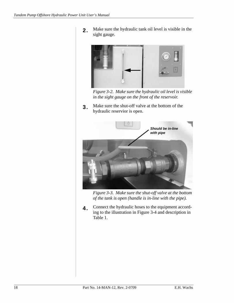
2. Make sure the hydraulic tank oil level is visible in the sight gauge.
Figure 3-2. Make sure the hydraulic oil level is visible in the sight gauge on the front of the reservoir.
3. Make sure the shut-off valve at the bottom of the hydraulic reservior is open.
Figure 3-3. Make sure the shut-off valve at the bottom of the tank is open (handle is in-line with the pipe).
4. Connect the hydraulic hoses to the equipment accord-ing to the illustration in Figure 3-4 and description in Table 1.
Should be in-line with pipe
18 Part No. 14-MAN-12, Rev. 2-0709 E.H. Wachs

Chapter 3, Operating Instructions: Setting Up the Power Unit
Figure 3-4. Connect hydraulic hoses as required to the Circuit 2 connectors (left) and Circuit 1 connec-tors (right). The top connectors are for pressure hoses and the bottom connectors are for return hoses.
The fuel tank does not have a gauge. To check fuel level, remove the cap and look into the tank. The fuel tank holds 16 gallons (61 liters).
5. Fill the fuel tank with enough diesel fuel for the planned operation. The burn rate for the engine is about 2.75 gallons (10.4 liters) of fuel per hour of operation.
Table 1: Hydraulic hose configurations
To operate the following circuit(s)...
Make the following hsse connections
Circuit 1 (up to 8 gpm) One hose pair to Circuit 1 connectors
Circuit 2 (up to 16 gpm) One hose pair to Circuit 2 connectors
Circuits 1 and 2 independently(8 gpm and 16 gpm)
One hose pair to Circuit 1 connectors, and one hose pair to Circuit 2 connectors
Circuits 1 and 2 combined (24 gpm)
One hose pair to Circuit 2 connectors
Pressure ports
Return (tank) ports
NOTE
E.H. Wachs Part No. 14-MAN-12, Rev. 2-0709 19

Tandem Pump Offshore Hydraulic Power Unit User’s Manual
Figure 3-5. Remove the fuel cap to fill the diesel tank.
Engine Oil Specification:Diesel engine oil CE grade or better. 10W-30 can be used, but is not recommended if routine engine maintenance is not peformed.
6. Make sure the engine oil is filled to the correct level.
Figure 3-6. Check the engine oil level using the dip-stick on the front side of the engine (behind the control panel).
7. Make sure the engine coolant is filled to the correct level in the overflow bottle.
NOTE
20 Part No. 14-MAN-12, Rev. 2-0709 E.H. Wachs
Chapter 3, Operating Instructions: Setting Up the Power Unit
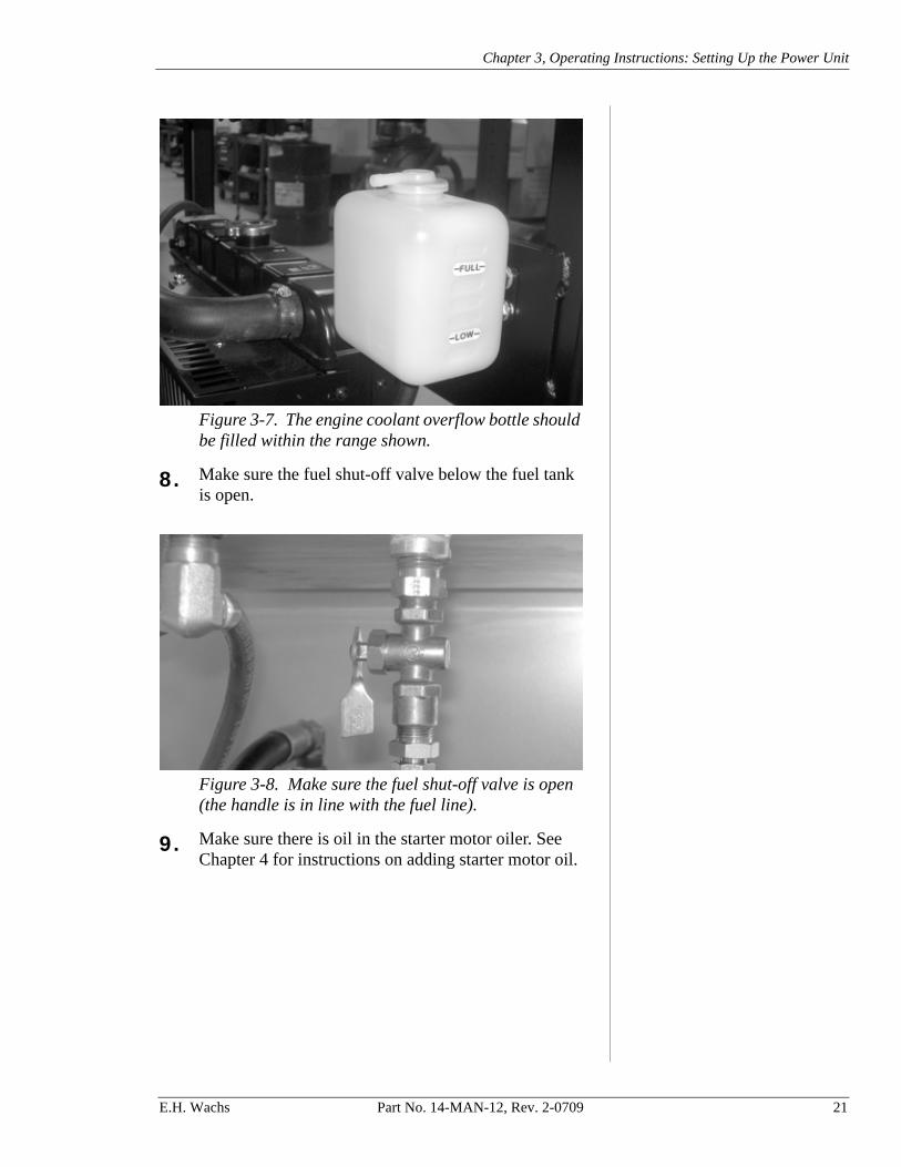
Figure 3-7. The engine coolant overflow bottle should be filled within the range shown.
8. Make sure the fuel shut-off valve below the fuel tank is open.
Figure 3-8. Make sure the fuel shut-off valve is open (the handle is in line with the fuel line).
9. Make sure there is oil in the starter motor oiler. See Chapter 4 for instructions on adding starter motor oil.
E.H. Wachs Part No. 14-MAN-12, Rev. 2-0709 21

Tandem Pump Offshore Hydraulic Power Unit User’s Manual
Figure 3-9. Check the oil level in the starter motor oiler, using the sight glass on the side of it. (Viewed from front of power unit.)
For optimum operation, the starter requires a clean air source with 200 cfm flow at 90 psi (5,663 l/min at 6.2 bar). Do not exceed 120 psi (8.3 bar).
10. Make sure the air supply for the starter is turned off at the air source.
11. Connect the air supply line to the connector on the back of the unit. (Inlet is 3/4”-14 taper pipe thread per ANSI B1.20.1.) Insert the locking key to secure the connection.
Figure 3-10. Attach the air supply line to the starter connector on the back of the HPU. Insert the locking pin (and whip-check, if required) to secure the connec-tion. The ball valve on/off handle should be closed, as shown. (The handle may go to either the left or right, depending on valve configuration.)
CAUTION
Starter connector
Ball valve on/off
22 Part No. 14-MAN-12, Rev. 2-0709 E.H. Wachs

Chapter 3, Operating Instructions: Start-Up and Operation
START-UP AND OPERATION
Do not let the fuel tank run dry. Shut off the HPU and refill the tank if the fuel level gets low.
1. Make sure the throttle, the engine shut-off, and the emergency shut-off on the control panel are pushed in, as shown in Figure 3-11.
Figure 3-11. Start the engine with the controls set as shown.
2. Set both flow control levers to the minimum flow set-ting.
Figure 3-12. Set the flow control levers at their mini-mum flow positions, as shown.
NOTE
Push the throttle all the way in to the idle position (hold the center button in while moving the throttle)
Push the engine shut-off all the way in
Push the emergency shut-off all the way in
E.H. Wachs Part No. 14-MAN-12, Rev. 2-0709 23

Tandem Pump Offshore Hydraulic Power Unit User’s Manual
3. Open the ball valve on the air starter connector. Pull the safety lock-out tab up the handle to allow it to turn.
Figure 3-13. Pull the safety lock-out tab back (1), and turn the handle to open the ball valve (2).
4. Turn on the air supply at the air source.
5. Push in the ENGINE START button and hold it until the engine starts. Release the button.
Figure 3-14. Push the ENGINE START button and hold it until the engine starts.
It is recommended that you close the ball valve and turn off the air supply after starting the HPU.
6. Pull the throttle control out about halfway to warm the engine up at medium speed.
1
2
NOTE
24 Part No. 14-MAN-12, Rev. 2-0709 E.H. Wachs
Chapter 3, Operating Instructions: Start-Up and Operation
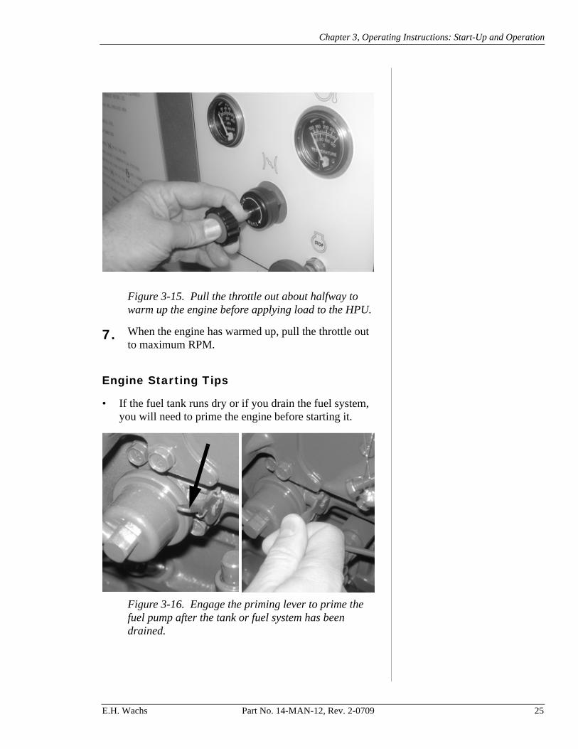
Figure 3-15. Pull the throttle out about halfway to warm up the engine before applying load to the HPU.
7. When the engine has warmed up, pull the throttle out to maximum RPM.
Engine Starting Tips
• If the fuel tank runs dry or if you drain the fuel system, you will need to prime the engine before starting it.
Figure 3-16. Engage the priming lever to prime the fuel pump after the tank or fuel system has been drained.
E.H. Wachs Part No. 14-MAN-12, Rev. 2-0709 25

Tandem Pump Offshore Hydraulic Power Unit User’s Manual
• If the ambient temperature is below 50° F (10° C), con-sider pre-warming the engine using a portable heater. The engine will be easier to start if it is warm.
• Cold temperatures affect the viscosity of the hydraulic oil, making starts difficult and limiting system perfor-mance. After starting the power unit, run the engine at idle until the hydraulic oil warms to 50° F (10° C).
Operating Checks
Monitor all system gauges continuously while operating the power unit.
While the power unit is running, make sure it is operating within the ranges listed in Table 2.
Two-Circuit Mode Operation
This section describes how to operate the HPU in two-cir-cuit mode. You can use both circuits at the same time, and independently control the flow on each circuit.
You will also use this mode to operate a single 8 gpm (30 l/min) or 16 gpm (60 l/min) circuit. Turn on flow only to the circuit you are using.
Before changing the flow mode, make sure the throttle is set at idle and both flow control levers are set at the minimum flow setting.
1. Connect the hydraulic hoses to the appropriate circuit connectors shown in Figure 3-17.
NOTE
Table 2: Normal operation checks
Operating Feature Operating Range
Engine oil pressure (high idle) 40-60 psi (2.8-4.1 bar)
Engine operating temperature 175-185° F (79-85° C)
Hydraulic system pressure Less than 2100 psi (145 bar)
Hydraulic oil temperature 50-180° F (10-82° C)
Hydraulic oil filter pressure Less than 25 psi (1.7 bar)
Hydraulic cooler fans Continuously spinning
CAUTION
26 Part No. 14-MAN-12, Rev. 2-0709 E.H. Wachs

Chapter 3, Operating Instructions: Start-Up and Operation
Figure 3-17. For operating in two-circuit mode, con-nect hydraulic hoses to both circuits as described.
2. Set the flow mode lever to the right to use both circuits (at 8 gpm [30 l/min] and 16 gpm [60 l/min] maxi-mum).
Figure 3-18. Set the flow mode lever to the right to operate the two circuits independently.
Typically, you can run the engine at maximum throttle (throttle pulled out to physical stop).
3. Hold in the throttle button while pulling the throttle until the engine is running at maximum. Release the button and turn the throttle locking ring clockwise to lock the throttle.
Circuit 2 pressure
Circuit 2 return
Circuit 1 pressure
Circuit 1 return
NOTE
E.H. Wachs Part No. 14-MAN-12, Rev. 2-0709 27

Tandem Pump Offshore Hydraulic Power Unit User’s Manual
Figure 3-19. Pull out the throttle to set the engine speed. You can turn the locking ring clockwise to lock the throttle position.
4. Move the flow control levers to adjust the flow as required for the tool(s) you are operating. Use the gauge for each circuit to monitor the flow.
Figure 3-20. Set the flow control levers to the desired flows. When the HPU is in two-circuit mode, you can adjust the flows separately.
5. Monitor the hydraulic oil temperature gauge (below the sight glasss on the front and back of the reservor).
Circuit 1 up to 8 gpm Circuit 2 up to 16 gpm
Flow gauges
Increase flow Increase flow
28 Part No. 14-MAN-12, Rev. 2-0709 E.H. Wachs

Chapter 3, Operating Instructions: Start-Up and Operation
If the temperature exceeds 180° F (82° C), set the flow levers to the minimum setting and let the engine run at operating speed until the oil temperature has gone down.
Figure 3-21. Monitor the hydraulic oil temperature as you operate the HPU. If the temperature goes over 180° F (82° C), turn off the flow control levers and run the HPU until the oil cools.
Do not use the emergency stop for a normal engine shutdown. Repeated use of the emergency stop could damage the engine.
6. If you need to stop the HPU immediately, pull the emergency stop handle on the control panel.
Figure 3-22. Pull the emergency off handle if you need to shut down the engine immediately.
7. When you have completed the operation, move the flow control levers back to the minimum flow setting.
IMPORTANT
E.H. Wachs Part No. 14-MAN-12, Rev. 2-0709 29

Tandem Pump Offshore Hydraulic Power Unit User’s Manual
Figure 3-23. Set the flow control levers back to the minimum flow setting before shutting down the HPU.
8. Turn the throttle locking ring counter-clockwise to unlock it. Hold in the throttle button and push the throttle in all the way so that the engine idles.
Figure 3-24. Push the throttle button and push in the throttle to return the engine to idle.
Minimum flowMinimum flow
30 Part No. 14-MAN-12, Rev. 2-0709 E.H. Wachs
Chapter 3, Operating Instructions: Start-Up and Operation
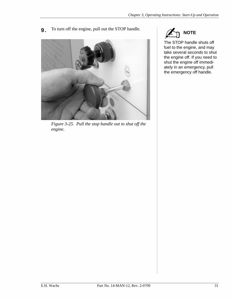
The STOP handle shuts off fuel to the engine, and may take several seconds to shut the engine off. If you need to shut the engine off immedi-ately in an emergency, pull the emergency off handle.
9. To turn off the engine, pull out the STOP handle.
Figure 3-25. Pull the stop handle out to shut off the engine.
NOTE
E.H. Wachs Part No. 14-MAN-12, Rev. 2-0709 31

Tandem Pump Offshore Hydraulic Power Unit User’s Manual
Combined-Circuit Mode Operation
This section describes how to operate the HPU with one combined 24 gpm (90 l/min)circuit.
Make sure the throttle is set at idle and both flow control levers are set at the minimum flow setting before changing the flow mode.
1. Attach the hydraulic hoses to the combined-circuit connectors as illustrated in Figure 3-26.
Figure 3-26. For operating in combined-circuit mode, connect hydraulic hoses to the combined circuit as shown.
2. Set the flow mode lever down to use one combined circuit at 24 gpm (90 l/min) maximum.
Figure 3-27. Set the flow mode lever down to operate a single combined circuit.
CAUTION
Combined-circuit pressure
Combined-circuit return
32 Part No. 14-MAN-12, Rev. 2-0709 E.H. Wachs

Chapter 3, Operating Instructions: Start-Up and Operation
Typically, you can run the engine at maximum throttle (throttle pulled out to physical stop).
3. Hold in the throttle button while pulling the throttle until the engine is running at maximum.
Figure 3-28. Hold in the button and pull the throttle out all the way, or to the desired engine operating speed.
4. Release the button and turn the throttle locking ring clockwise to lock the throttle.
Figure 3-29. Turn the ring clockwise to lock it.
NOTE
E.H. Wachs Part No. 14-MAN-12, Rev. 2-0709 33

Tandem Pump Offshore Hydraulic Power Unit User’s Manual
When you are operating in combined-flow mode, the flow gauge for Circuit #1 does not register flow.
5. Move the flow control levers to adjust the flow as required for the tool(s) you are operating. Use the gauge on Circuit #2 to monitor the flow.
Figure 3-30. Set the flow control levers to the desired flows. The flow from both circuits is added together, and the Circuit #2 flow gauge registers the total.
6. Monitor the hydraulic oil temperature gauge (below the sight glasss on the front and back of the reservor). If the temperature exceeds 180° F (82° C), set the flow levers to the minimum setting and let the engine run at operating speed until the oil temperature has gone down.
Figure 3-31. Monitor the hydraulic oil temperature as you operate the HPU. If the temperature goes over 180° F (82° C), turn off the flow control levers and run the HPU until the oil cools.
NOTE
Circuit 1 contributes up to 8 gpm
Circuit 2 contributes up to 16 gpm
Use Circuit #2 flow and pressure gauges for combined flow (up to 24 gpm)
Increase flow Increase flow
34 Part No. 14-MAN-12, Rev. 2-0709 E.H. Wachs

Chapter 3, Operating Instructions: Start-Up and Operation
Do not use the emergency stop for a normal engine shutdown. Repeated use of the emergency stop could damage the engine.
7. If you need to stop the HPU immediately, pull the emergency stop handle on the control panel.
Figure 3-32. Pull the emergency off handle if you need to shut down the engine immediately.
8. When you have completed the operation, move the flow control levers back to the minimum flow setting.
Figure 3-33. Set the flow control levers back to the minimum flow setting before shutting down the HPU.
9. Turn the throttle locking ring counter-clockwise to unlock it. Hold in the throttle button and push the throttle in all the way so that the engine idles.
IMPORTANT
Minimum flowMinimum flow
E.H. Wachs Part No. 14-MAN-12, Rev. 2-0709 35

Tandem Pump Offshore Hydraulic Power Unit User’s Manual
Figure 3-34. Push the throttle button and push in the throttle to return the engine to idle.
The STOP handle shuts off fuel to the engine, and may take several seconds to shut the engine off. If you need to shut the engine off immedi-ately in an emergency, pull the emergency off handle.
10. To turn off the engine, pull out the STOP handle.
Figure 3-35. Pull the stop handle out to shut off the engine.
NOTE
36 Part No. 14-MAN-12, Rev. 2-0709 E.H. Wachs

Chapter 4, Maintenance
Chapter 4
Maintenance
DISABLING THE STARTER FOR SERVICE
Before performing any service on the HPU, disable the starter so that the engine cannot be started while you work on the unit. Follow all required lockout and tagout proce-dures when performing service
Disengage the starter as described below:
1. Make sure the air supply to the starter air line is off.
2. Close the ball valve on the starter air connector. The ball valve has relief to let the pressure off the air starter.
Figure 4-1. Close the ball valve on the starter air connector (shiown in closed position).
In This Chapter
DISABLING THE STARTER FOR SERVICE
HYDRAULIC SYSTEM
ENGINE MAINTENANCE AND SERVICE
AIR STARTER SYSTEM
CHECKING FOR LEAKS
E.H. Wachs Part No. 14-MAN-12, Rev. 2-0709 37
Tandem Pump Offshore Hydraulic Power Unit User’s Manual
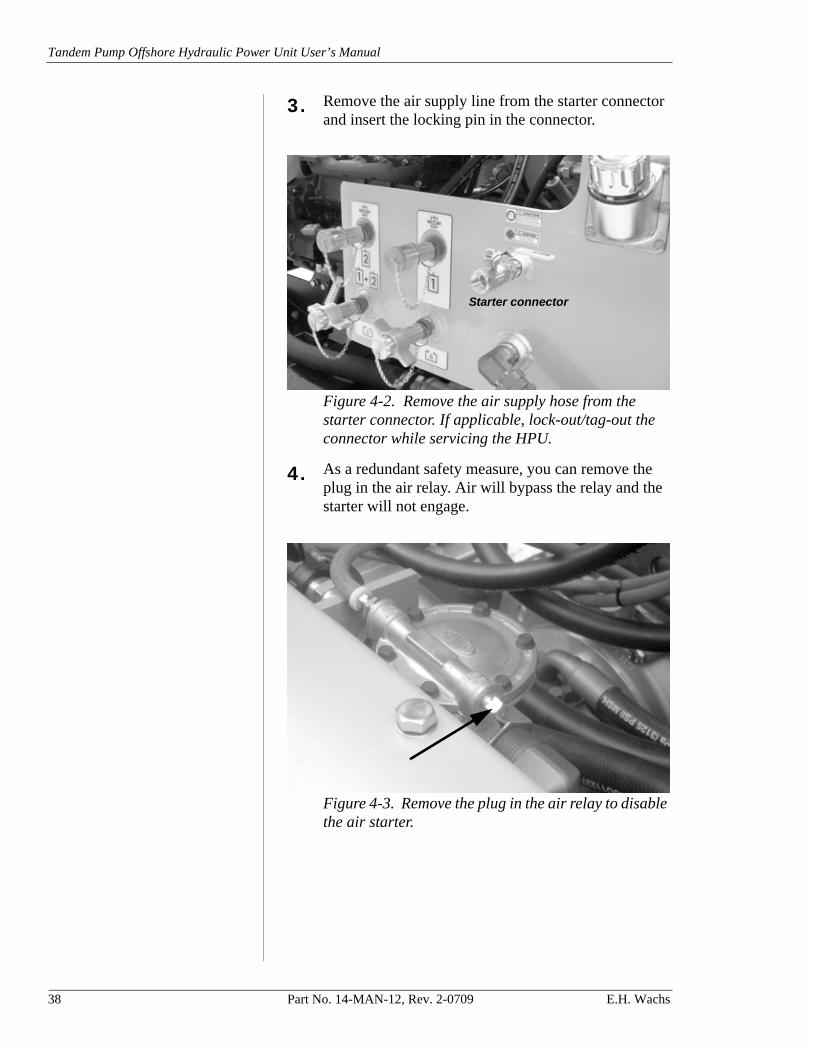
3. Remove the air supply line from the starter connector and insert the locking pin in the connector.
Figure 4-2. Remove the air supply hose from the starter connector. If applicable, lock-out/tag-out the connector while servicing the HPU.
4. As a redundant safety measure, you can remove the plug in the air relay. Air will bypass the relay and the starter will not engage.
Figure 4-3. Remove the plug in the air relay to disable the air starter.
Starter connector
38 Part No. 14-MAN-12, Rev. 2-0709 E.H. Wachs

Chapter 4, Maintenance: Hydraulic System
HYDRAULIC SYSTEM
When servicing components of the hydraulic system (such as replacing a pump), you can close the hydraulic suction line from the reservoir to keep the reservoir from draining.
Figure 4-4. Push the valve handle back (perpendicu-lar to pipe) to close the hydraulic suction line coming out of the hydraulic reservoir.
• Replace the hydraulic oil filter periodically. Frequency of replacement depends the operating load and how clean the hydraulic oil is kept. Monitor the pressure indicator gauge on the front of the HPU whenever it is running, and change the filter when the gauge reads in the red zone (above 25 psi/1.7 bar).
E.H. Wachs Part No. 14-MAN-12, Rev. 2-0709 39

Tandem Pump Offshore Hydraulic Power Unit User’s Manual
Figure 4-5. Replace the hydraulic oil filter when the filter pressure gauge reads above 25 psi (1.7 bar).
Figure 4-6. Unscrew the hydraulic oil filter to replace it.
• Each time you drain the hydraulic reservoir, check the strainer in the bottom of the reservoir and clean it if nec-essary. You can see the strainer with the reservoir cover removed.
40 Part No. 14-MAN-12, Rev. 2-0709 E.H. Wachs

Chapter 4, Maintenance: Hydraulic System
Figure 4-7. Remove the screws in the top of the hydraulic tank and remove the top to access and check the oil strainer.
Figure 4-8. Remove the strainer by removing the out-let piping and unscrewing the strainer from the outlet port.
Make sure the reservoir and circuit are clean and free of dirt/debris before refilling the reservoir with hydraulic oil.
• Change the hydraulic oil periodically, especially if the oil looks dirty or discolored, or has a burnt odor. It is recommended to clean the system by flushing and filter-ing using an external slave pump.
Strainer
NOTE
E.H. Wachs Part No. 14-MAN-12, Rev. 2-0709 41

Tandem Pump Offshore Hydraulic Power Unit User’s Manual
Figure 4-9. Drain the hydraulic oil by removing the drain plug and then opening the drain valve.
• When re-filling the reservoir, use filtered oil. Fill the reservoir with enough fluid so that you can see it in the temperature/level gauges on the front and back of the reservoir.
• When intially starting the HPU after changing the oil, remove all trapped air from the system. All inlet connec-tions must be tight to prevent air leaks.
Figure 4-10. Bleed air at the flow control valves (one shown).
Remove plug before opening valve
42 Part No. 14-MAN-12, Rev. 2-0709 E.H. Wachs

Chapter 4, Maintenance: Engine Maintenance and Service
Figure 4-11. Bleed air from above the flow meters (one shown).
Cooler
• Inspect the cooler regularly for corrosion and for dirty or clogged heat transfer service. Remove any dirt and dust by washing, brushing, or blowing with compressed air. To remove grease or oil, use a non-flammable degreasing solution (one that is safe on copper, steel, and aluminum) and then a hot rinse. You can also steam clean the cooler.
• Once a year, disconnect piping to the cooler and circu-late a degreasing agent through the unit and the rest of the hydraulic system. Service the tank strainer and replace the hydraulic filter after performing this service.
ENGINE MAINTENANCE AND SERVICE
Check the engine oil and engine coolant levels every time you use the HPU.
The Kubota manufacturer’s manual is provided with the HPU. Refer to it for the periodic maintenance schedule, and for performing service and repair on the diesel engine. The following table summarizes the service intervals prescribed in the Kubota manual; refer to the manual for detailed instructions.
E.H. Wachs Part No. 14-MAN-12, Rev. 2-0709 43

Tandem Pump Offshore Hydraulic Power Unit User’s Manual
Notes:• The jobs indicated by + must be done after the first 50 hours
of operation.*1 Air cleaner should be cleaned more often in dusty condi-
tions than in normal conditions.*2 After 6 times of cleaning.*3 Consult your local Kubota dealer for this service.*4 Replace only if necessary.• When the battery is used for less than 100 hours in a year,
check its electrolyte yearly (refillable batteries only).• The items listed with @ are registered as emission-related
critical parts by Kubota in the U.S. EPA nonroad emission regulation.
44 Part No. 14-MAN-12, Rev. 2-0709 E.H. Wachs

Chapter 4, Maintenance: Engine Maintenance and Service
Fluid Levels
Check the engine oil using the dipstick on the front side of the engine (behind the control panel).
Figure 4-12. Check the engine oil level using the dip-stick on the front side of the engine.
Check the level of the engine coolant in the overflow tank
Figure 4-13. The engine coolant overflow tank should be filled within the range shown.
Air Filters
Check the air filter, and blow it out or replace it as neces-sary. There are two filter elements, one inside the other.
Maximum
Minimum
E.H. Wachs Part No. 14-MAN-12, Rev. 2-0709 45

Tandem Pump Offshore Hydraulic Power Unit User’s Manual
Figure 4-14. Release the three spring clips on the fil-ter cover to remove the cover.
Figure 4-15. Check the outer filter and blow it out or replace it if necessary.
46 Part No. 14-MAN-12, Rev. 2-0709 E.H. Wachs

Chapter 4, Maintenance: Air Starter System
Figure 4-16. Remove the outer filter to check the inner filter. Blow it out or replace it as necessary.
Spark Arrestor
Perform the following checks of the engine exhaust spark arrestor at the specified intervals.
• Daily—Examine the spark arrestor for any sign of gas leakage, cracks, or significant areas of damage (such as dents more than a few millimeters in depth).
• Three-Monthly—Remove the spark arrestor, and tap it with a soft mallet to loosen any internal deposits. Shake it to remove loosened deposits and to check for loose baffles.
• Six-Monthly/1500 hours—Examine the exhaust dis-charge in darkness while repeatedly loading and acceler-ating the engine. If you see any sparks, the spark arrestor must be replaced.
If any problems are identified during these checks, do not use the engine until you have made the necessary repairs.
AIR STARTER SYSTEM
Peform the following air system checks on a regular basis:
E.H. Wachs Part No. 14-MAN-12, Rev. 2-0709 47

Tandem Pump Offshore Hydraulic Power Unit User’s Manual
• Oiler operation—every time you use the HPU, check the oil level in the oiler and verify that it is working.
• Air leakage—look and listen for damaged components and air leaks. Replace any worn or damaged compo-nents.
• Loose connections—check all threaded connections for tightness.
• Hose wear—check for kinked, crushed, damaged, or worn hoses. Damaged hoses can restrict or reduce air flow and lead to unpredictable system behavior.
• Dirt buildup—clean any accumulated dirt and grime from air system components. Dirt buildup may hide damage or potentially hazardous situations.
If you find any components requiring repair or replacement, shut the system down immediately and do not use it until the repairs have been completed.
Starter Motor Oiler
Use Wachs air motor oil (part no. 02-407-00, one pint) or a good quality SAE 10 weight oil.
Each time you use the HPU, check the oil level in the air starter oiler. Add oil through the port in the top of the oiler, shown in Figure 4-17.
Adjust the drip rate knob on top of the oiler to the maximum by turning it all the way counter-clockwise.
Figure 4-17. Check the oil level in the oiler, and fill as necessary.
NOTE
Check oil level in sight glass
Remove screw cap to add oil
Adjust the drip rate knob to the maximum (turn counter-clockwise)
48 Part No. 14-MAN-12, Rev. 2-0709 E.H. Wachs

Chapter 4, Maintenance: Checking for Leaks
CHECKING FOR LEAKS
Each day before operation, check all hydraulic and engine components for oil leaks. Keeping the bottom of the frame pan clean will help you detect leaks.
There is an access panel on the front of the HPU. Remove the panel to access the front part of the unit for cleanout or checking for leaks. Turn the 4 locking pins counter-clock-wise to release them and remove the panel. The pins are captivated to prevent them from falling out of the panel.
Figure 4-18. Turn the 4 locking pins counter-clock-wise to remove the front access panel.
TROUBLESHOOTING
Engine
The table below lists common troubleshooting issues. See the Kubota engine manual for more detailed procedures.
Remove Re-tighten
E.H. Wachs Part No. 14-MAN-12, Rev. 2-0709 49

Tandem Pump Offshore Hydraulic Power Unit User’s Manual
Symptom Potential Cause/Solution
Engine won’t turn over
Inadequate air supply.Recommended pressure and flow to air starter connection: 90 psi (6.2 bar) @ 200 SCFM (5663 l/min)
Plug is removed from air relay.Replace plug in air relay.
Air relay is malfunctioning.Service air relay.
Air intake shut-off valve malfunc-tioning.Service air intake shut-off valve.
Engine turns over but won’t start
Fuel tank is empty.Fill fuel tank.
Fuel line valve is closed.Open fuel line valve below fuel tank.
Air in the fuel line.Bleed air from the fuel system.
Air filter is clogged.Blow out or replace filter ele-ments.
Fuel filter is clogged.Replace fuel filter.
Air intake shut-off valve malfunc-tioning.Service air intake shut-off valve.
50 Part No. 14-MAN-12, Rev. 2-0709 E.H. Wachs

Chapter 4, Maintenance: Troubleshooting
Engine starts, but will not stay running.
Air filter is clogged.Blow out or replace filter ele-ments.
Fuel filter is clogged.Replace fuel filter.
Air vent cock on the engine is open.Close the air vent cock. See Kubota manual for instructions.
Emergency shut-off is pulled out partially or completely.Push in emergency shut-off.
Overspeed function in air intake shut-off out of adjustment or mal-functioning.Service air intake shut-off valve.
Engine overloaded.Set flow control valves to mini-mum flow settings, increase engine RPM to maximum before increasing flow output.
Engine overloaded—hydraulic malfunction.Service hydraulic system.
Engine malfunction.Service engine.
Symptom Potential Cause/Solution
E.H. Wachs Part No. 14-MAN-12, Rev. 2-0709 51

Tandem Pump Offshore Hydraulic Power Unit User’s Manual
Hydraulic System
Symptom Potential Cause/Solution
No flow and no pressure on either hydraulic circuit.
The valve on the suction line coming out of the hydraulic res-ervoir is closed.Open the suction line valve.
The hydraulic reservoir oil level is too low.Fill the reservoir until oil is visible in the sight glass.
The suction strainer in the bot-tom of the hydraulic reservoir is plugged and relief valve is stuck closed.Clean suction strainer; see main-tenance section.
Sheared drive key or hub.Service drive system.
Pump malfunction.Service pump.
Pressure, but no flow on either hydraulic circuit.
Flowmeter malfunction.Refer to flowmeter troubleshoot-ing section.
Hydraulic lines not properly con-nected.Check hydraulic connections.
Obstruction in cooler assembly, return filter, or return lines.Check return line for obstruction.
Obstruction in connected hydrau-lic system.Check connected hydraulic sys-tem.
Flow control valve set to mini-mum flow.Increase flow setting on flow con-trol valves.
52 Part No. 14-MAN-12, Rev. 2-0709 E.H. Wachs

Chapter 4, Maintenance: Troubleshooting
Flow, but no pressure on either hydraulic circuit.
Pressure gauge malfunction.Replace pressure gauge.
Relief valves (part of flow control valve) set low.Set relief valve to required pres-sure. Factory setting: 2100 psi (145 bar).
Flow mode lever out of position.Select appropriate flow mode.
Hydraulic leak.Check for leaks.
Pump malfunction.Service pump.
Flow control valve malfunction.Replace flow control valve.
No flow on only one hydraulic cir-cuit.
Flow mode lever out of position.Select appropriate flow mode.
Hydraulic leak.Check for leaks.
Pump malfunction.Service pump.
Flow control valve malfunction.Replace flow control valve.
Not cooling adequately.
Heat load exceeds cooler heat rejection.Remove or decrease heat load and allow cooler to lower temper-ature.
Cooler fans not spinning—jammed fan blades.With system off, unjam fan.
Cooler fans not spinning—hydraulic leak.Fix leak.
Cooler fans not spinning—fan motor malfunction.Service fan motor.
Both cooler fans not spinning—gear pump malfunction.Service gear pump.
Heat exchanger is fouled.Clean heat exchanger—see maintenance section.
Symptom Potential Cause/Solution
E.H. Wachs Part No. 14-MAN-12, Rev. 2-0709 53

Tandem Pump Offshore Hydraulic Power Unit User’s Manual
Flow meter sticks and won’t return to “no flow” position.
Foreign matter in the meter is holding the internal parts from returning.Disassemble and inspect the meter for contamination; install proper filtration to prevent prob-lem from re-occurring.
A surge in fluid flow separated the follower from the magnet inside the meter.Disassemble the meter and reas-semble separated parts.
Flow meter window tube is crack-ing or crazing.
Lexan window tube was dam-aged by incompatible cleaning solution.Replace Lexan tube if necessary. To prevent re-occurrence, use soap and water.
Flow meter scale is fogging or coming loose.
Ambient or fluid temperature is too high.See Hydraulics section for possi-ble solutions.
Scale was damaged by incom-patible cleaning solution.Replace scale if necessary. To prevent re-occurrence, clean with soap and water.
Symptom Potential Cause/Solution
54 Part No. 14-MAN-12, Rev. 2-0709 E.H. Wachs

Chapter 5, Parts List and Ordering Information
Chapter 5
Parts List and Ordering Information
ORDERING INFORMATION
To place an order, request service, or get more detailed information on any E.H. Wachs products, call us at one of the following numbers:
U.S. and Canada 800-323-8185
International: 01-847-537-8800
Ordering Replacement Parts
When ordering parts, refer to the parts list in this chapter. Please provide the part description and part number for all parts you are ordering. Specify your machine model num-ber and serial number when ordering.
Repair Information
Please call us for an RMA (Return Material Authorization) number before returning any equipment for repair or fac-tory service. We will advise you of shipping and handling. When you send the equipment, please include the following information:• Your name/company name• Your address• Your phone number• A description of the problem or the work to be done.
In This Chapter
ORDERING INFORMATION
DRAWINGS AND PARTS LISTS
E.H. Wachs Part No. 14-MAN-12, Rev. 2-0709 55

Tandem Pump Offshore Hydraulic Power Unit User’s Manual
Before we perform any repair, we will estimate the work and inform you of the cost and the time required to com-plete it.
Warranty Information
Enclosed with the manual is a warranty card. Please fill out the registration card and return to E.H. Wachs. Retain the owner’s registration record and warranty card for your information.
Return Goods Address
Return equipment for repair to the following address.
E.H. Wachs600 Knightsbridge ParkwayLincolnshire, Illinois 60069 USA
DRAWINGS AND PARTS LISTS
The following bill of materials and drawings will help you identify parts for service and ordering. The drawings at the end of the chapter illustrate the electrical and hydraulic schematics.
56 Part No. 14-MAN-12, Rev. 2-0709 E.H. Wachs

2
8
4
1011
9
517
1816
1
16
6
3
10
1817
7
14
12
15
13
ITEM
PART
NU
MBE
RQ
TYD
ESCR
IPTI
ON
108
-073
-010
1W
ELD
MEN
T, F
RAM
E2
08-0
73-1
751
TOP
CO
VER
ASS
Y.3
08-0
73-3
572
1-1/
2 N
PT P
LUG
408
-073
-400
1FR
ON
T PA
NEL
508
-073
-403
1C
OO
LER
AN
D F
ILTE
R A
SSY.
608
-073
-404
1EN
GIN
E A
SSEM
BLY
708
-073
-413
1HY
D. R
ESER
VO
IR A
SSY.
W/
FITT
ING
S8
08-0
73-4
151
FUEL
TA
NK
ASS
EMBL
Y9
90-0
55-0
610
NUT
, 1/4
-20
NYL
OC
K10
90-1
30-0
628
BHC
S, 1
/4-2
0 X
5/8
SS18
-811
90-1
55-5
310
WA
SHER
, 1/4
FLA
T SS
18-8
1290
-171
-10
4HH
CS,
3/8
-16
X 1
SS18
-813
90-1
75-0
14
NUT
, 3/8
-16
HEX
SS18
-814
90-1
75-5
14
WA
SHER
, 3/8
FLA
T SS
18-8
1590
-175
-52
4W
ASH
ER, 3
/8 S
PLIT
RIN
G S
S18-
816
90-1
91-1
010
HHC
S, 1
/2-1
3 X
1.0
SS18
-817
90-1
95-5
210
WA
SHER
, 1/2
FLA
T SS
18-8
1890
-195
-58
10W
ASH
ER, 1
/2 L
OC
K SS
18-8
Tand
em P
ump
Offs
hore
HPU
14-0
00-1
2M
ain
Ass
embl
y

NO
TES: W
ARN
ING
! DO
NO
T EX
CEE
D 1
20 P
SI (1
0 BA
R)1.
SUPP
LY C
LEA
N R
EGUL
ATE
D A
IR2.
REC
OM
MEN
DED
PN
EUM
ATIC
REQ
UIRE
MEN
TS: 2
00 S
CFM
(566
3 LP
M);
90 P
SI (6
.2 B
AR)
3.BE
SUR
E TO
FO
LLO
W A
LL R
EQUI
RED
LO
CKO
UT A
ND
TA
GO
UT P
ROC
EDUR
ES W
HEN
SER
VIC
ING
EQ
UIPM
ENT.
4.FO
R M
ORE
INFO
RMA
TION
SEE
: OSH
A S
TAN
DA
RD-2
9 C
FR, P
ART
191
0.14
7, A
PPEN
DIX
A, T
HE C
ON
TRO
L O
FHA
ZARD
OUS
EN
ERG
Y.
PNEU
MA
TIC
SYST
EM S
CHEM
ATI
CIT
EMPA
RT N
UM
BER
QTY
.D
ESCR
IPTI
ON
108
-073
-069
1A
IR R
ELA
Y2
08-0
73-0
681
STA
RTER
PUS
H BU
TTO
N3
08-0
73-1
151
LUBR
ICA
TOR
408
-073
-088
1A
IR S
TART
ER5
08-0
73-0
501
EXHA
UST
MUF
FLER
608
-073
-152
4'HO
SE, 1
/4" H
IGH
TEM
P7
08-0
73-1
516'
HOSE
, 3/4
" HIG
H TE
MP
808
-073
-167
13/
4" B
ALL
VA
LVE,
LO
CKI
NG
VEN
TED
Tand
em P
ump
Offs
hore
HPU
14-0
00-1
208
-073
Sys
tem
Sch
emat
ics,
2 of
2

4
2
65
1
3
2
47
ITEM
PART
NU
MBE
R Q
TY.
DES
CRIP
TIO
N
108
-073
-061
2BR
AC
KET,
FLO
WM
ETER
208
-073
-062
2TO
P BR
AC
KET,
FLO
WM
ETER
308
-073
-078
1FL
OW
MET
ER 3
-30
GPM
408
-073
-163
2T-
AD
APT
ER, -
12M
J x
- 12M
P x
-12F
P5
08-0
73-3
091
BUSH
ING
, -12
MP
x -0
4 FP
6
08-0
73-3
101
ELBO
W, -
04 M
J x
-04M
P 90
708
-073
-311
1A
DA
PTER
, -12
MJ
x -1
2 M
P ST
RAIG
HT
Tand
em P
ump
Offs
hore
HPU
14-0
00-1
208
-073
-350
Circ
uit 2
Flo
w M
eter
Ass
embl
y

1
3
4
2
ITEM
PART
NU
MBE
R Q
TY.
DES
CRIP
TIO
N
108
-073
-182
1FL
OW
CO
NTR
OL
VA
LVE
w/
RELI
EF2
08-0
73-1
831
AD
APT
ER, -
12 M
Jx -1
2 M
ORB
STR
AIG
HT3
08-0
73-1
841
ELBO
W, -
16 M
J x
-12
MA
ORB
90
408
-073
-185
1EL
BOW
, -12
MJ
x -1
2 M
AO
RB 9
0
Tand
em P
ump
Offs
hore
HPU
14-0
00-1
208
-073
-351
Circ
uit 2
Flo
w C
ontr
ol A
ssem
bly

32
1
3
5
46
7
ITEM
PART
NU
MBE
R Q
TY.
DES
CRIP
TIO
NM
AN
UFA
CTU
RER
108
-073
-059
1FL
OW
MET
ER 1
-10
GPM
LAKE
MO
NITO
RS2
08-0
73-0
612
BRA
CKE
T, F
LOW
MET
ER3
08-0
73-0
622
TOP
BRA
CKE
T, F
LOW
MET
ER4
08-0
73-1
631
T-A
DA
PTER
, -12
MJ
x - 1
2MP
x -1
2FP
BREN
NA
N
508
-073
-307
1EL
BOW
, -12
MJ
x -1
2 M
P 90
BREN
NA
N6
08-0
73-3
091
BUSH
ING
, -12
MP
x -0
4 FP
BR
ENN
AN
708
-073
-310
1EL
BOW
, -04
MJ
x -0
4MP
90BR
ENN
AN
Tand
em P
ump
Offs
hore
HPU
14-0
00-1
208
-073
-352
Circ
uit 1
Flo
w M
eter
Ass
embl
y

3 1
2
4
ITEM
PART
NU
MBE
R Q
TY.
DES
CRIP
TIO
N
108
-073
-075
1FL
OW
CO
NTR
OL
VA
LVE
w/
RELI
EF
208
-073
-314
1EL
BOW
, -12
MJ
x -1
0 M
AO
RB 9
03
08-0
73-3
151
-16M
J - 1
0 M
AO
RB 9
04
08-0
73-3
161
AD
APT
ER, -
12 M
J x
-10
MO
RB S
TRIG
HT
Tand
em P
ump
Offs
hore
HPU
14-0
00-1
208
-073
-353
Circ
uit 1
Flo
w C
ontr
ol A
ssem
bly

3
2
1
2
ITEM
PART
NU
MBE
R Q
TY.
DES
CRIP
TIO
N
108
-073
-063
1V
ALV
E, 3
/4" 3
-WA
Y2
08-0
73-3
072
ELBO
W, -
12 M
J x
-12
MP
903
08-0
73-3
111
AD
APT
ER, -
12 M
J x
-12
MP
STRA
IGHT
Tand
em P
ump
Offs
hore
HPU
14-0
00-1
208
-073
-354
Thr
ee-W
ay V
alve
Ass
embl
y

1 87
9
13
12
11
10
40
171920
4
5
39
14
3
16
15
15
16
2
6
622
22
30
2625
31
23
24
27
CUT OUTER CABLE SLEEVE TO 40" 1"
CUT OUTER CABLE SLEEVE TO 44" 1"
28
28
21
32
34
28
33
35
PUMP 2 IN
29
TANK
CIRCUIT 2/1+2PRESSURE
CIRCUIT 1PRESSURE
TANK
PUMP 1 IN
37
36
34
38
ENGINE OILPRESSURE
CIRCUIT 1PRESSURE RELIEF
CIRCUIT 2PRESSURE RELIEF
ITEM PART NUMBER QTY. DESCRIPTION
1 08-073-020 1 CONTROL PANEL
2 08-073-064 1 AIR SHUTOFF T-HANDLE
3 08-073-068 1 AIR START PUSH VALVE
4 08-073-070 1 GAUGE, PRESSURE
5 08-073-071 1 GAUGE, TEMP.
6 08-073-077 2 0-3000 PSI PRESSURE GAUGE
7 08-073-100 1 CONTROL LABEL
8 08-073-101 1 OPERATING INSTRUCTIONS
9 08-073-103 1 DIRECTION LABEL 1
10 08-073-104 1 HYD. #1 LABEL
11 08-073-105 1 HYD. #2 LABEL
12 08-073-106 1 DIRECTION LABEL 1 + 2
13 08-073-109 1 DIRECTION LABEL 1
14 08-073-131 1 CONTROL CABLE, FUEL SHUT OFF
15 08-073-152 2 HOSE, 1/4" HIGH TEMP
16 08-073-153 2 HOSE FITTING, 1/8" NPT x 1/4" HOSE
17 08-073-165 4 LATCH
18 08-073-166 4 PALSTIC RETAINER
19 08-073-170 1 COVER PLATE
20 08-073-171 1 BACK COVER BRACKET
21 08-073-188 1 ADAPTER, 1/8 F NPT x -4 JIC 90 ELBOW
22 08-073-337 2 ADAPTER, -4 JIC -4 NPTF
23 08-073-350 1 FLOW METER ASSEMBLY, CIRCUIT 2
24 08-073-351 1 FLOW CONTROL ASSEMBLY, CIRCUIT 2
25 08-073-352 1 FLOW METER ASSEMBLY, CIRCUIT 1
26 08-073-353 1 FLOW CONTROL ASSEMBLY, CIRCUIT 1
27 08-073-354 1 3 WAY VALVE ASSEMBLY
28 08-073-421 2 HOSE ASSEMBLY, PRESSURE GAUGE
29 08-073-423 1 HOSE ASSEMBLY, CIRCUIT 1 PRESSURE
30 08-073-424 1 HOSE ASSEMBLY, CIRCUIT 2 PRESSURE
31 08-073-425 1 HOSE ASSEMBLY, CIRCUIT 2 TANK
32 08-073-426 1 HOSE ASSEMBLY, CIRCUIT 1 TANK
33 08-073-427 1 HOSE ASSEMBLY, 3 WAY INLET
34 08-073-429 2 HOSE ASSEMBLY, PUMP OUTLET
35 08-073-431 1 HOSE ASSEMBLY, CIRCUIT 1 + 2
36 08-073-432 1 HOSE ASSEMBLY, CIRCUIT 2
37 08-073-433 1 HOSE ASSEMBLY, CIRCUIT 1 FLOWMETER
38 08-073-435 1 HOSE ASSEMBLY, ENGINE OIL PRESSURE
39 17-065-00 1 VERNIER CONTROL 30 SERIES
40 90-401-03 1 LABEL, EAR AND EYE PROTECTION
Tandem Pump Offshore HPU14-000-1208-073-400 Front Panel

A
10
20 11
1
3
16
6
4
15
24
8
9
5
12
13
2
22
14
21
17
23
23
18
19
25
29
30
3231
28
33
7
35
35
4
34
DETAIL A
26
27 28
ITEM PART NUMBER QTY. DESCRIPTION
1 08-073-023 1 MAIN HYD. PUMP2 08-073-024 1 GEAR PUMP3 08-073-041 1 3 CODE 61 FLANGE ADPATER4 08-073-050 1 EXHAUST MUFFLER5 08-073-065 4 MOTOR MOUNT6 08-073-072 1 SAE B PUMP SPACER7 08-073-089 1 MUFFLER/SPARK ARRESTOR8 08-073-099 1 ENGINE ASSEMBLY
9 08-073-118 1 HUB
10 08-073-121 1 EXHAUST FLANGE BRACKET ASSY.11 08-073-122 1 OVERFLOW BOTTLE ASSEMBLY12 08-073-123 2 SAE FLANGE KIT13 08-073-135 1 -237 O-RING14 08-073-155 2 CLAMP15 08-073-311 1 ADAPTER, -12 MJ x -12 MP STRAIGHT16 08-073-319 1 ADAPTER, -32 MJ -32 MAORB 9017 08-073-343 1 ADAPTER, -8 MJ -8 MAORB18 08-073-344 1 RAIN CAP EXTENSION 2.5" x 12"19 08-073-349 4 HHCS, 5/8-11" X 3-1/2"20 08-073-405 1 AIR INTAKE ASSEMBLY21 08-073-410 1 SUCTION HOSE ASSEMBLY22 08-073-420 1 HOSE ASSEMBLY GEAR PUMP TO
SUCTION23 08-073-429 2 HOSE ASSEMBLY, PUMP OUTLET24 08-073-434 1 HOSE ASSEMBLY AUX PUMP TO
COOLER25 90-205-59 4 WASHER, 5/8 FLAT26 08-073-142 4 HHCS, M12 x 40 MM27 90-195-58 4 WASHER, 1/2 LOCK SS18-828 90-195-52 6 WASHER, 1/2 FLAT SS18-829 08-073-168 1 RAIN CAP, 2.5"30 90-171-07 8 HHCS, 3/8-16 X 3/4 SS18-831 90-175-51 8 WASHER, 3/8 FLAT SS18-832 90-175-52 8 WASHER, 3/8 SPLIT RING SS18-833 90-091-18 2 HHCS, 1/2-13 X 1-3/434 08-073-186 1 ADAPTER, -8 MJ X -6 MORB 9035 08-073-181 2 MUFFLER CLAMP, 2.5 OD 304 SS
Tandem Pump Offshore HPU14-000-1208-073-404 Engine Assembly

1
5
12
13
14
5
7
8
2
6
4
3
10
13
11
9
CIR
CUI
T 1
AN
D C
IRC
UIT
2 RE
TURN
RETU
RN T
O T
AN
K
FRO
M A
UX P
UMP
RETU
RN T
O T
AN
K
ITEM
PART
NU
MBE
R Q
TY.
DES
CRIP
TIO
N
108
-073
-079
1RA
DIA
TOR
CO
OLE
R
208
-073
-080
1RE
TURN
FIL
TER
ASS
EMBL
Y
308
-073
-083
1V
ISUA
L FI
LTER
GA
GE
IND
ICA
TOR
408
-073
-300
1A
DA
PTER
, -20
MJ
x -2
4 M
AO
RB 9
0
508
-073
-302
4A
DA
PTER
, -8
MJ
-8 M
ORB
STR
IAG
HT
608
-073
-303
1A
DA
PTER
, -20
MJ
x -2
0 M
P 90
708
-073
-304
1A
DA
PTER
, -24
MO
RB x
-20
FP S
TRA
IGHT
808
-073
-305
1A
DA
PTER
, -20
MP
x -2
0 M
P 90
908
-073
-360
1RE
DUC
ER, 1
/8 N
PT F
X 3
/8 N
PT M
1008
-073
-411
1HO
SE A
SSEM
BLY
TAN
K TO
CO
OLE
R
1108
-073
-414
1HO
SE A
SSEM
BLY
TAN
K TO
FIL
TER
1208
-073
-416
1HO
SE A
SSEM
BLY
CO
OLE
R TO
TA
NK
1308
-073
-417
1HO
SE A
SSEM
BLY
1408
-073
-434
1HO
SE A
SSEM
BLY
AUX
PUM
P TO
CO
OLE
R
Tand
em P
ump
Offs
hore
HPU
14-0
00-1
208
-073
-403
Coo
ler a
nd F
ilter
Ass
embl
y

SCA
LE:1
:4
4
1 3 2
ITEM
PART
NU
MBE
R Q
TY.
DES
CRIP
TIO
N
108
-073
-081
125
PSI
HEA
D A
SSY.
1-1
/4 N
PT2
08-0
73-0
821
HYD
RAUL
IC F
ILTE
R3
08-0
73-2
211
SQUA
RE-C
UT F
ILTE
R G
ASK
ET4
90-1
28-0
12
1/8"
NPT
PIP
E PL
UG, S
OC
KET
HEA
D
Tand
em P
ump
Offs
hore
HPU
14-0
00-1
208
-073
-080
Ret
urn
Filte
r Ass
embl
y

45
4
14
2
3
6.2
6.1
7
7
5
8
ITEM
PART
NU
MBE
RQ
TY.
DES
CRIP
TIO
N1
08-0
73-0
601
AIR
INTA
KE S
HUTO
FF2
08-0
73-0
861
MO
DIF
IED
ELB
OW
308
-073
-087
1RE
DUC
ING
SLE
EVE
408
-073
-091
32-
1/2"
RUB
BER
HOSE
x 3
"5
08-0
73-0
921
2.5"
TUB
E x
12"
508
-073
-124
1EN
GIN
E A
IR F
ILTE
R6.
1 0
8-07
3-12
61
SAFE
TY F
ILTE
R6.
2 0
8-07
3-12
71
FILT
ER7
08-0
73-1
288
#48
LIN
ED 3
00 S
S HO
SE C
LAM
P8
08-0
73-1
301
CO
NTR
OL
CA
BLE
ASS
EMBL
Y
Tand
em P
ump
Offs
hore
HPU
14-0
00-1
208
-073
-405
Air
Inta
ke A
ssem
bly

7
6
5
2
4
1
3
8
ITEM
PART
NU
MBE
R Q
TY.
DES
CRIP
TIO
N
108
-073
-022
1ST
RAIN
ER, S
UCTIO
N2
08-0
73-0
841
2" B
RASS
BA
LL V
ALV
E3
08-0
73-3
181
AD
APT
ER, 1
/2 M
P x
-8M
J 90
408
-073
-322
1A
DA
PTER
, -32
MP
-32
MP
508
-073
-323
1A
DA
PTER
, -32
NPT
, -32
NPT
608
-073
-324
1LO
W P
RESS
UR T
, -32
NPT
-32
NPT
-32
NPT
708
-073
-325
1A
DA
PTER
, -32
MP
-8 F
P RE
DUC
ER8
08-0
73-4
201
HOSE
ASS
EMBL
Y G
EAR
PUM
P TO
SUC
TION
Tand
em P
ump
Offs
hore
HPU
14-0
00-1
208
-073
-409
Suc
tion
Ass
embl
y

1113
9
8
9
14
2
5
7
6
12
1
3
4
10
15
ITEM PART NUMBER QTY. DESCRIPTION
1 08-073-025 1 HYD. RESERVOIR WELDMENT ASSY.2 08-073-039 1 RESERVOIR COVER PLATE3 08-073-107 1 REAR PANEL LABEL4 08-073-108 1 REAR LABEL 25 08-073-110 1 RESERVOIR TOP SEAL6 08-073-111 12 SEALING WASHER7 08-073-112 12 1/2-13" X 7/8" HEX BOLT8 08-073-114 1 SIDE MOUNT FILLER CAP RUBBER GASKET9 08-073-116 12 SEALING WASHER10 08-073-220 1 PRESSURE LABEL11 08-073-406 1 SIDE MOUNT FILLER CAP ASSY.12 08-073-408 2 LEVEL GAUGE w/ THERMOMETER13 90-051-08 6 HHCS, 1/4-20 X 7/814 90-055-04 6 NUT, 1/4-20 JAM15 90-401-03 1 LABEL, EAR AND EYE PROTECTION
Tandem Pump Offshore HPU14-000-1208-073-407 Hydraulic Reservoir Assembly

6
16
7
17
13
154
?
23
10
24
11
14
20
19
9
21
22
85
18
26
2
1
26
2 1
25
3
12
29
28
27
30
ITEM PART NUMBER QTY. DESCRIPTION
1 08-073-132 2 QUICK COUPLING DUST CAP 2 08-073-133 2 QUICK COUPLING DUST PLUG 3 08-073-167 1 VENTED BALL VALVE4 08-073-303 1 ADAPTER, -20 MJ x -20 MP 905 08-073-321 1 LOW PRESSURE T, -20 -20 -206 08-073-333 1 ADAPTER, -20 MJ -20 MP7 08-073-334 1 ADAPTER, -8 MJ -8 MP8 08-073-335 1 REDUCER, -20 MP -08 FP9 08-073-336 2 ADAPTER, -16 MJ x -16 MP 9010 08-073-347 2 ADAPTER, -12 MP x -12 MJ STRAIGHT BULKHEAD 11 08-073-348 2 ADAPTER -12 MP -12 MP12 08-073-356 1 1" NPT PLUG13 08-073-407 1 HYD. RESERVOIR ASSY. 14 08-073-409 1 SUCTION ASSY.15 08-073-411 1 HOSE ASSEMBLY TANK TO COOLER16 08-073-414 1 HOSE ASSEMBLY TANK TO FILTER17 08-073-416 1 HOSE ASSEMBLY COOLER TO TANK18 08-073-418 1 AIR RELAY-LUBRICATOR ASSEMBLY19 08-073-423 1 HOSE ASSEMBLY, CIRCUIT 1 PRESSURE20 08-073-424 1 HOSE ASSEMBLY, CIRCUIT 2 PRESSURE21 08-073-425 1 HOSE ASSEMBLY, CIRCUIT 2 TANK22 08-073-426 1 HOSE ASSEMBLY, CIRCUIT 1 TANK23 14-006-02 2 COUPLING, -12 NIPPLE24 14-007-02 2 COUPLING, -12 WING NUT25 90-218-01 1 NIPPLE, 3/4 CLOSE LP26 90-235-51 5 WASHER, 1" SAE FLAT27 08-073-139 1 -12 EXTERNAL PIPE PLUG28 08-073-138 1 -12 -12, LOW PRESSURE BALL VALVE29 08-073-328 1 HEX NIPPLE, -12 MP x -12 MP 30 08-073-332 2 -12 BULKHEAD NUT
Tandem Pump Offshore HPU14-000-1208-073-413 Hydraulic Reservoir and Fittings

4
31
2
1
ITEM
PART
NU
MBE
R Q
TY.
DES
CRIP
TIO
N
108
-073
-154
2HO
SE S
PLIT
CLA
MP
208
-073
-156
1HO
SE F
ITTIN
G, -
32 J
IC x
2" H
OSE
308
-073
-157
78"
2" S
UCTIO
N H
OSE
408
-073
-326
1HO
SE F
ITTIN
G, 2
" NPT
x 2
" HO
SE
Tand
em P
ump
Offs
hore
HPU
14-0
00-1
208
-073
-410
Suc
tion
Hos
e A
ssem
bly

11
13
12
4
6
8
10
3
1
7
9
103
5
FRO
M F
UEL
RETU
RN
TO E
NG
INE
FUEL
FIL
TER
DRA
IN V
ALV
EUSE
LOC
TITE
569
HYD
RAUL
IC S
EALA
NT
FOR
SEA
LIN
G A
LL T
HREA
DED
CO
NN
ECTIO
NS
35" L
ON
G
25" L
ON
G
ITEM
PART
NU
MBE
R Q
TY.
DES
CRIP
TIO
N
108
-073
-090
2M
ARI
NE
FUEL
SHU
T O
FF V
ALV
E
208
-073
-136
1FU
EL T
AN
K3
08-0
73-1
432
AD
APT
ER B
USHI
NG
, 1/2
" x 3
/8" N
PT4
08-0
73-1
441
AD
APT
ER, 1
/8 N
PT X
1/2
-20
SAE
455
08-0
73-1
451
PLUG
, HEX
HEA
D 1
/2 N
PT6
08-0
73-1
461
HOSE
FITT
ING
, -5
SAE
45 x
1/4
HO
SE7
08-0
73-1
471
HOSE
FITT
ING
, 3/8
NPT
x 5
/16
HOSE
808
-073
-148
1HO
SE, 1
/4" F
UEL
908
-073
-149
1HO
SE, 5
/16"
FUE
L10
08-0
73-1
502
#6
Hose
Cla
mp
1190
-191
-15
4HH
CS,
1/2
-13
X 1-
1/2
GRD
8 U
LTRA
CO
AT
1290
-195
-52
4W
ASH
ER, 1
/2 F
LAT
SS18
-813
90-1
95-5
84
WA
SHER
, 1/2
LO
CK
SS18
-8
Tand
em P
ump
Offs
hore
HPU
14-0
00-1
208
-073
-415
Fue
l Tan
k A
ssem
bly

FROM AIR START VALVEON CONTROL PANEL
TO AIR START VALVE ON CONTROL PANEL
2
6
713
12
15
5
4
1
6
3
8
4
5
11
710
9
3
8
TO AIR STARTER
CUT LENGTH - 36"
CUT LENGTH - 10"
CUT LENGTH - 32"
CUT LENGTH - 43"
13
14
ITEM PART NUMBER DESCRIPTION
1 08-073-069 1 AIR RELAY VALVE
2 08-073-115 1 LUBRICATOR
3 08-073-151 2 HOSE, 3/4" HIGH TEMP4 08-073-152 2 HOSE, 1/4" HIGH TEMP
5 08-073-158 2 HOSE FITTING, 1/4" NPT x 1/4" HOSE
6 08-073-159 2 ELBOW, -12 MJ x -16 MP 90
7 08-073-160 2 HOSE FITTING, -12 JIC x 3/4" HOSE
8 08-073-161 2 HOSE FITTING, -12 JIC x 3/4" HOSE 90
9 08-073-162 1 STREET TEE, -12 MP x -12 FP x -12 FP
10 08-073-307 1 ELBOW, -12 MJ x -12 MP 90
11 08-073-309 1 BUSHING, -12 MP x -04 FP
12 08-073-330 1 ADAPTER, -12 FJS -12 MP
13 08-073-331 2 REDUCER BUSHING, -16 MPT - 12 FPT
14 08-073-332 1 -12 BULKHEAD NUT
15 08-073-347 1 ADAPTER, -12 MP x -12 MJ STRAIGHT BULKHEAD
Tandem Pump Offshore HPU14-000-1208-073-418 Air Relay Assembly