
Talk About Simple! - Phoenix Pumps, Inc. · PDF fileas simple as replacing a ... Wrapflex...
16
WRAPFLEX ® Talk About Simple!
-
Upload
nguyenkien -
Category
Documents
-
view
219 -
download
5
Transcript of Talk About Simple! - Phoenix Pumps, Inc. · PDF fileas simple as replacing a ... Wrapflex...
WRAPFLEX®
Talk About Simple!
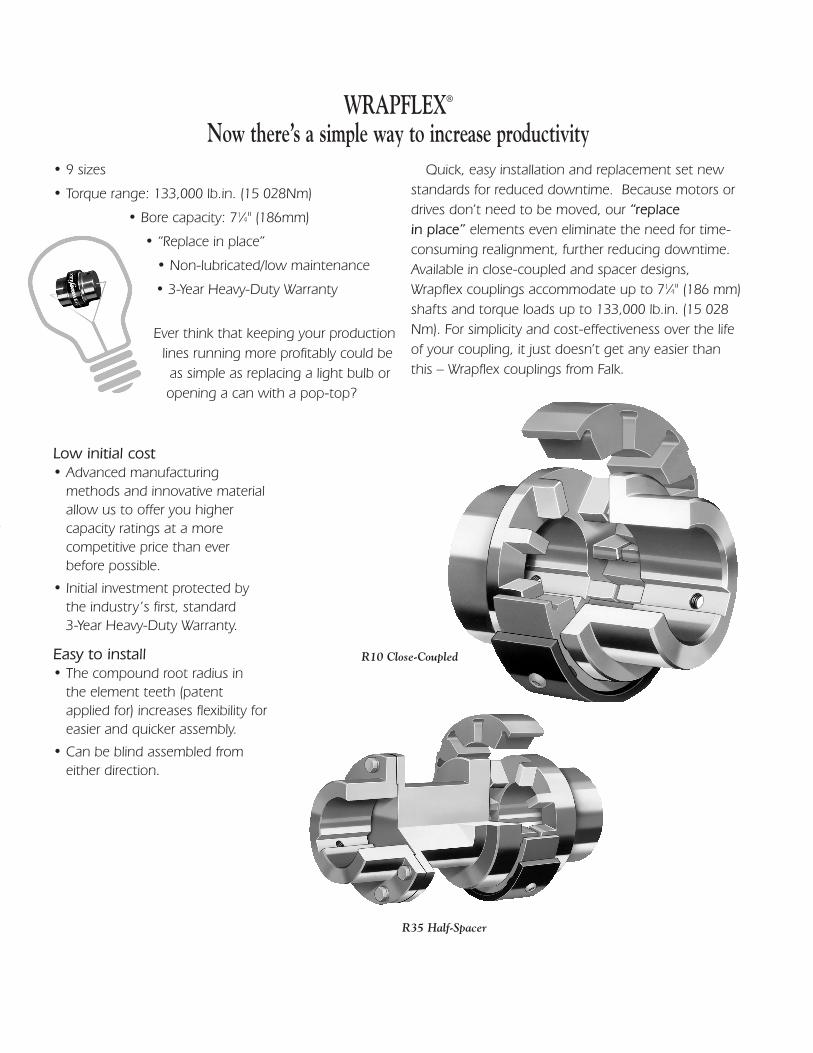
R35 Half-Spacer
WRAPFLEX®
Now there’s a simple way to increase productivity• 9 sizes
• Torque range: 133,000 lb.in. (15 028Nm)
• Bore capacity: 71⁄4" (186mm)
• “Replace in place”
• Non-lubricated/low maintenance
• 3-Year Heavy-Duty Warranty
Ever think that keeping your productionlines running more profitably could beas simple as replacing a light bulb oropening a can with a pop-top?
Low initial cost• Advanced manufacturing
methods and innovative materialallow us to offer you highercapacity ratings at a morecompetitive price than everbefore possible.
• Initial investment protected bythe industry’s first, standard3-Year Heavy-Duty Warranty.
Easy to install• The compound root radius in
the element teeth (patentapplied for) increases flexibility foreasier and quicker assembly.
• Can be blind assembled fromeither direction.
Quick, easy installation and replacement set newstandards for reduced downtime. Because motors ordrives don’t need to be moved, our “replace in place” elements even eliminate the need for time-consuming realignment, further reducing downtime.Available in close-coupled and spacer designs,Wrapflex couplings accommodate up to 71⁄4" (186 mm)shafts and torque loads up to 133,000 lb.in. (15 028Nm). For simplicity and cost-effectiveness over the lifeof your coupling, it just doesn’t get any easier thanthis – Wrapflex couplings from Falk.
R10 Close-Coupled
Tough, long-lasting• Polyurethane element has
excellent wear and chemicalresistance, and a operating temperature of -40° C (-40° F) to95° C (200° F).
• Hubs made from carbon steel formaximum strength.
• Weather-resistant, high-gradenylon cover is standard.
• Optional carbon steel coverswith black epoxy coating forhighly corrosive, severe-dutyapplications. (Standard for sizes60-80.)
Safety first• Two stainless steel button-head
cap screws, positioned 180°apart, prevent relative motionbetween cover and element andprovide a positive means ofretaining the cover to theelement.
• Flexible element is retained afterfailure, helping minimize thepotential for damage or personalinjury.
Quick and easy retrofits• Compact design eliminates the
need for coupling guardredesign on existing applications.
• Stock finished bores in popularsizes and taper bores, whichaccept Q.D. and TaperLockbushings, are available from ourworldwide distribution networkfor off-the-shelf availability.
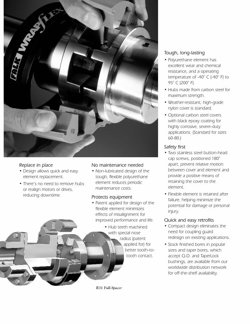
Replace in place• Design allows quick and easy
element replacement.
• There’s no need to remove hubsor realign motors or drives,reducing downtime.
No maintenance needed• Non-lubricated design of the
tough, flexible polyurethaneelement reduces periodic maintenance costs.
Protects equipment• Patent applied for design of the
flexible element minimizeseffects of misalignment forimproved performance and life.
• Hub teeth machined with special nose
radius (patentapplied for) for better tooth-to-tooth contact.
R31 Full-Spacer
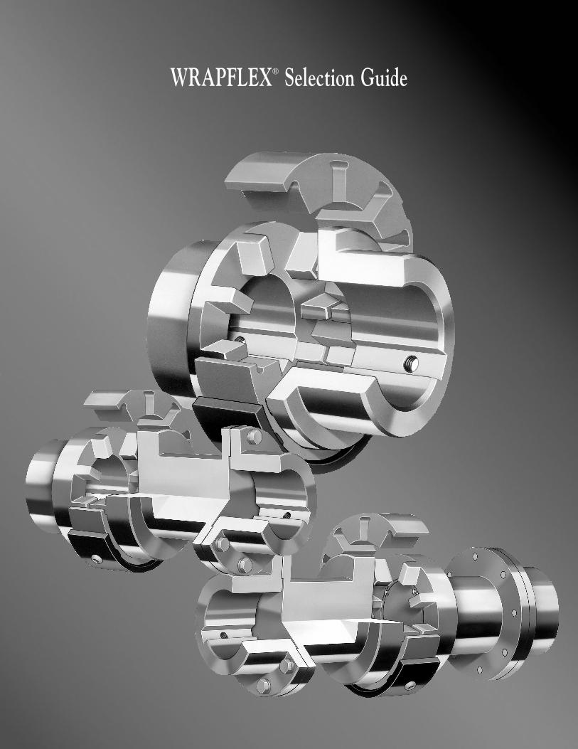
WRAPFLEX® Selection Guide
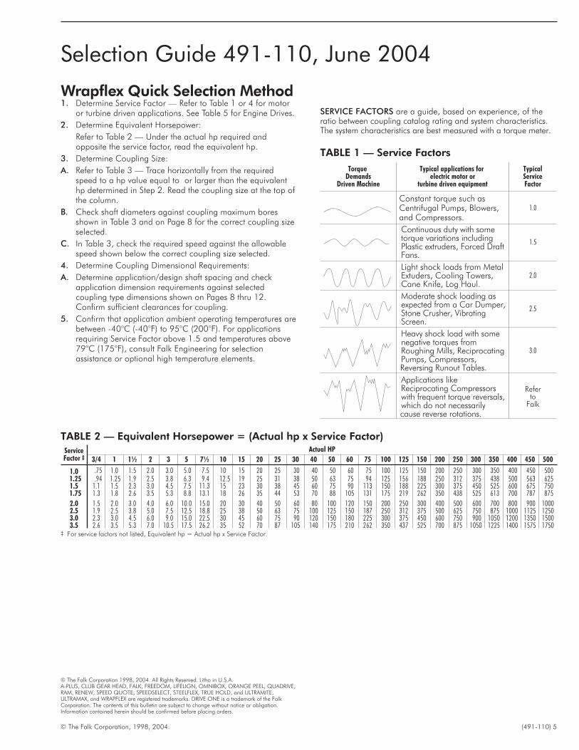
Wrapflex Quick Selection Method1. Determine Service Factor — Refer to Table 1 or 4 for motor
or turbine driven applications. See Table 5 for Engine Drives.
2. Determine Equivalent Horsepower:
Refer to Table 2 — Under the actual hp required andopposite the service factor, read the equivalent hp.
3. Determine Coupling Size:
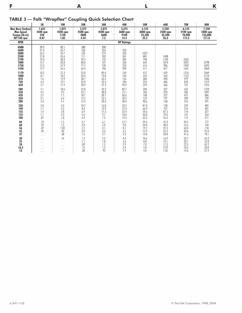
A. Refer to Table 3 — Trace horizontally from the requiredspeed to a hp value equal to or larger than the equivalenthp determined in Step 2. Read the coupling size at the top ofthe column.
B. Check shaft diameters against coupling maximum boresshown in Table 3 and on Page 8 for the correct coupling sizeselected.
C. In Table 3, check the required speed against the allowablespeed shown below the correct coupling size selected.
4. Determine Coupling Dimensional Requirements:
A. Determine application/design shaft spacing and checkapplication dimension requirements against selectedcoupling type dimensions shown on Pages 8 thru 12.Confirm sufficient clearances for coupling.
5. Confirm that application ambient operating temperatures arebetween -40°C (-40°F) to 95°C (200°F). For applicationsrequiring Service Factor above 1.5 and temperatures above79°C (175°F), consult Falk Engineering for selectionassistance or optional high temperature elements.
© The Falk Corporation, 1998, 2004. (491-110) 5
TorqueDemands
Driven Machine
Typical applications forelectric motor or
turbine driven equipment
TypicalServiceFactor
Constant torque such asCentrifugal Pumps, Blowers,and Compressors.
1.0
Continuous duty with sometorque variations includingPlastic extruders, Forced DraftFans.
1.5
Light shock loads from MetalExtuders, Cooling Towers,Cane Knife, Log Haul.
2.0
Moderate shock loading asexpected from a Car Dumper,Stone Crusher, VibratingScreen.
2.5
Heavy shock load with somenegative torques fromRoughing Mills, ReciprocatingPumps, Compressors,Reversing Runout Tables.
3.0
Applications likeReciprocating Compressorswith frequent torque reversals,which do not necessarilycause reverse rotations.
Referto
Falk
SERVICE FACTORS are a guide, based on experience, of theratio between coupling catalog rating and system characteristics.The system characteristics are best measured with a torque meter.
TABLE 1 — Service Factors
TABLE 2 — Equivalent Horsepower = (Actual hp x Service Factor)
ServiceFactor ‡
Actual HP
3/4 1 1½ 2 3 5 7½ 10 15 20 25 30 40 50 60 75 100 125 150 200 250 300 350 400 450 500
1.0 .75 1.0 1.5 2.0 3.0 5.0 7.5 10 15 20 25 30 40 50 60 75 100 125 150 200 250 300 350 400 450 5001.25 .94 1.25 1.9 2.5 3.8 6.3 9.4 12.5 19 25 31 38 50 63 75 94 125 156 188 250 312 375 438 500 563 6251.5 1.1 1.5 2.3 3.0 4.5 7.5 11.3 15 23 30 38 45 60 75 90 113 150 188 225 300 375 450 525 600 675 7501.75 1.3 1.8 2.6 3.5 5.3 8.8 13.1 18 26 35 44 53 70 88 105 131 175 219 262 350 438 525 613 700 787 875
2.0 1.5 2.0 3.0 4.0 6.0 10.0 15.0 20 30 40 50 60 80 100 120 150 200 250 300 400 500 600 700 800 900 10002.5 1.9 2.5 3.8 5.0 7.5 12.5 18.8 25 38 50 63 75 100 125 150 187 250 312 375 500 625 750 875 1000 1125 12503.0 2.3 3.0 4.5 6.0 9.0 15.0 22.5 30 45 60 75 90 120 150 180 225 300 375 450 600 750 900 1050 1200 1350 15003.5 2.6 3.5 5.3 7.0 10.5 17.5 26.2 35 52 70 87 105 140 175 210 262 350 437 525 700 875 1050 1225 1400 1575 1750
‡ For service factors not listed, Equivalent hp = Actual hp x Service Factor.
Selection Guide 491-110, June 2004
© The Falk Corporation 1998, 2004. All Rights Reserved. Litho in U.S.A.A-PLUS, CLUB GEAR HEAD, FALK, FREEDOM, LIFELIGN, OMNIBOX, ORANGE PEEL, QUADRIVE,RAM, RENEW, SPEED QUOTE, SPEEDSELECT, STEELFLEX, TRUE HOLD, and ULTRAMITE,ULTRAMAX, and WRAPFLEX are registered trademarks. DRIVE ONE is a trademark of the FalkCorporation. The contents of this bulletin are subject to change without notice or obligation.Information contained herein should be confirmed before placing orders.
6 (491-110) © The Falk Corporation, 1998, 2004.
F A L K
TABLE 3 — Falk “Wrapflex” Coupling Quick Selection Chart5R 10R 20R 30R 40R 50R 60R 70R 80R
Max Bore (Inches) 1.625 1.875 2.375 2.875 3.375 4.125 5.250 6.125 7.250Max Speed 4500 rpm 4500 rpm 4500 rpm 4500 rpm 3600 rpm 3000 rpm 2500 rpm 2100 rpm 1800 rpm
Torque (lb-in) 550 1150 2800 4600 9100 22,200 35,500 70,900 133,000HP/100 rpm 0.87 1.82 4.44 7.3 14.4 35.2 56.3 112.5 211.0
RPM HP Ratings
4500 39.3 82.1 200 3283600 31.4 65.7 160 263 5203000 26.2 54.7 133 219 433 10572500 21.8 45.6 111 182 361 881 14082100 18.3 38.3 93.3 153 303 740 1183 23621800 15.7 32.8 80.0 131 260 634 1014 2025 37981750 15.3 31.9 77.7 128 253 616 986 1969 36931450 12.7 26.5 64.4 106 209 511 817 1631 3060
1170 10.2 21.3 52.0 85.4 169 412 659 1316 24691000 8.7 18.2 44.4 73.0 144 352 563 1125 2110870 7.6 15.9 38.7 63.5 126 306 490 979 1836720 6.3 13.1 32.0 52.6 104 254 406 810 1519650 5.7 11.9 28.9 47.4 93.9 229 366 731 1372
580 5.1 10.6 25.8 42.3 83.7 204 327 652 1224520 4.5 9.5 23.1 38.0 75.1 183 293 585 1097420 3.7 7.7 18.7 30.7 60.6 148 237 472 886350 3.1 6.4 15.5 25.5 50.5 123 197 394 739280 2.4 5.1 12.4 20.4 40.4 98.6 158 315 591
230 2.0 4.2 10.2 16.8 33.2 81.0 130 259 485190 1.7 3.5 8.4 13.9 27.4 66.9 107 214 401155 1.4 2.8 6.9 11.3 22.4 54.6 87.3 174 327125 1.1 2.3 5.6 9.1 18.0 44.0 70.4 141 264100 .87 1.8 4.4 7.3 14.4 35.2 56.3 112 211
84 .73 1.5 3.7 6.1 12.1 29.6 47.3 94.5 17768 .59 1.2 3.0 5.0 9.8 24.0 38.3 76.5 14356 .49 1.02 2.5 4.1 8.1 19.7 31.5 63.0 11845 .39 .82 2.0 3.3 6.5 15.9 25.3 50.6 95.037 . . . .68 1.6 2.7 5.3 13.0 20.8 41.6 78.1
30 . . . .55 1.3 2.2 4.3 10.6 16.9 33.7 63.325 . . . . . . 1.1 1.8 3.6 8.8 14.1 28.1 52.820 . . . . . . .89 1.5 2.9 7.0 11.3 22.5 42.2
16.5 . . . . . . .73 1.2 2.4 5.8 9.29 18.6 34.813 . . . . . . .58 .95 1.9 4.6 7.32 14.6 27.4
Service Factors
© The Falk Corporation, 1998, 2004. (491-110) 7
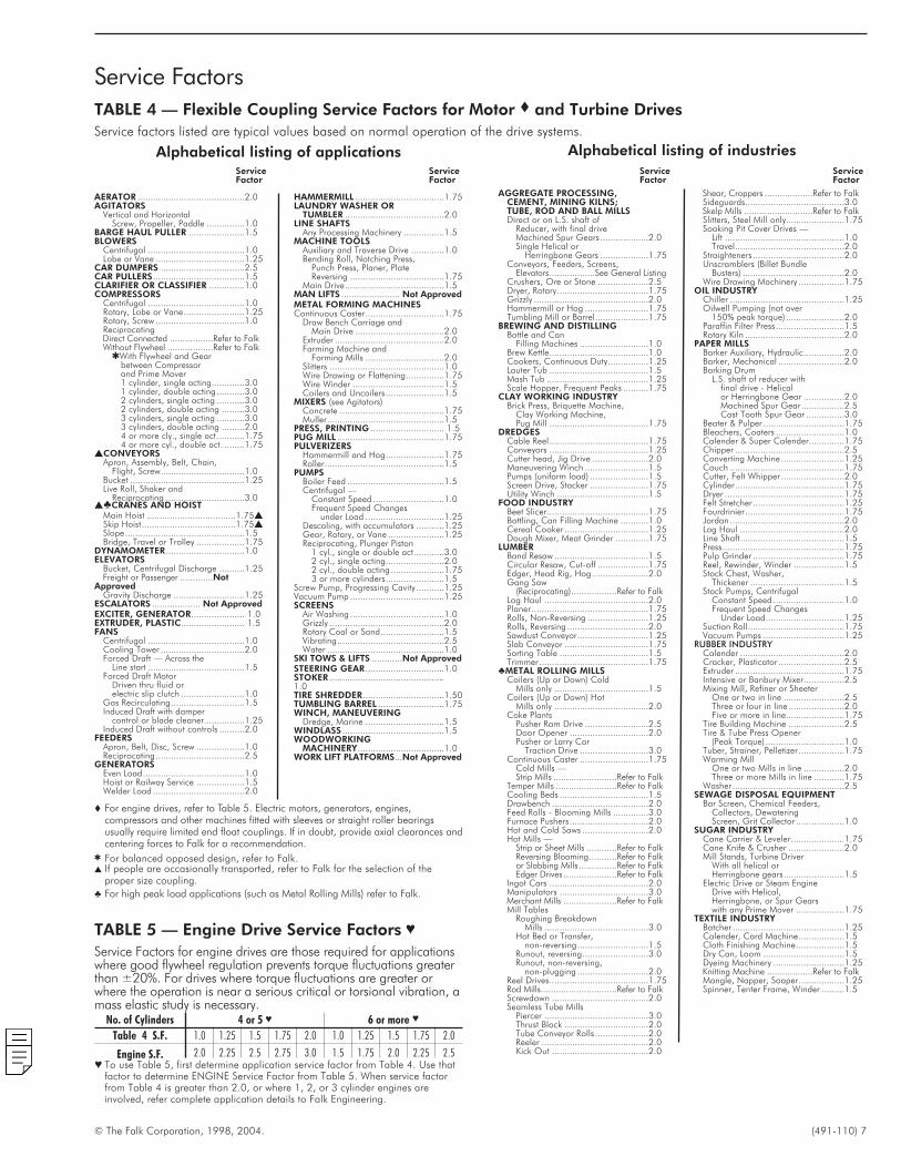
TABLE 4 — Flexible Coupling Service Factors for Motor � and Turbine Drives
Service factors listed are typical values based on normal operation of the drive systems.
AERATOR ..........................................2.0AGITATORS
Vertical and HorizontalScrew, Propeller, Paddle ...............1.0
BARGE HAUL PULLER ......................1.5BLOWERS
Centrifugal ......................................1.0Lobe or Vane ...................................1.25
CAR DUMPERS .................................2.5CAR PULLERS....................................1.5CLARIFIER OR CLASSIFIER ..............1.0COMPRESSORS
Centrifugal ......................................1.0Rotary, Lobe or Vane........................1.25Rotary, Screw ...................................1.0ReciprocatingDirect Connected .................Refer to FalkWithout Flywheel ..................Refer to Falk
�With Flywheel and Gearbetween Compressorand Prime Mover1 cylinder, single acting.............3.01 cylinder, double acting ...........3.02 cylinders, single acting ...........3.02 cylinders, double acting .........3.03 cylinders, single acting ...........3.03 cylinders, double acting .........2.04 or more cly., single act...........1.754 or more cyl., double act. ........1.75
�CONVEYORSApron, Assembly, Belt, Chain,
Flight, Screw.................................1.0Bucket .............................................1.25Live Roll, Shaker and
Reciprocating ...............................3.0��CRANES AND HOIST
Main Hoist ...................................1.75�Skip Hoist.....................................1.75�Slope...............................................1.5Bridge, Travel or Trolley ...................1.75
DYNAMOMETER ...............................1.0ELEVATORS
Bucket, Centrifugal Discharge ..........1.25Freight or Passenger .............Not
ApprovedGravity Discharge ............................1.25
ESCALATORS ................... Not ApprovedEXCITER, GENERATOR..................... 1.0EXTRUDER, PLASTIC......................... 1.5FANS
Centrifugal ......................................1.0Cooling Tower .................................2.0Forced Draft — Across the
Line start ......................................1.5Forced Draft Motor
Driven thru fluid orelectric slip clutch .........................1.0
Gas Recirculating.............................1.5Induced Draft with damper
control or blade cleaner................1.25Induced Draft without controls ..........2.0
FEEDERSApron, Belt, Disc, Screw ...................1.0Reciprocating...................................2.5
GENERATORSEven Load........................................1.0Hoist or Railway Service ...................1.5Welder Load ....................................2.0
HAMMERMILL ...................................1.75LAUNDRY WASHER OR
TUMBLER .......................................2.0LINE SHAFTS
Any Processing Machinery ................1.5MACHINE TOOLS
Auxiliary and Traverse Drive .............1.0Bending Roll, Notching Press,
Punch Press, Planer, PlateReversing .....................................1.75
Main Drive.......................................1.5MAN LIFTS ....................... Not ApprovedMETAL FORMING MACHINESContinuous Caster...............................1.75
Draw Bench Carriage andMain Drive ...................................2.0
Extruder ...........................................2.0Farming Machine and
Forming Mills ...............................2.0Slitters .............................................1.0Wire Drawing or Flattening...............1.75Wire Winder ....................................1.5Coilers and Uncoilers .......................1.5
MIXERS (see Agitators)Concrete .........................................1.75Muller..............................................1.5
PRESS, PRINTING ............................. 1.5PUG MILL ..........................................1.75PULVERIZERS
Hammermill and Hog.......................1.75Roller...............................................1.5
PUMPSBoiler Feed ......................................1.5Centrifugal —
Constant Speed ............................1.0Frequent Speed Changes
under Load ...............................1.25Descaling, with accumulators ...........1.25Gear, Rotary, or Vane ......................1.25Reciprocating, Plunger Piston
1 cyl., single or double act............3.02 cyl., single acting.......................2.02 cyl., double acting .....................1.753 or more cylinders.......................1.5
Screw Pump, Progressing Cavity ...........1.25Vacuum Pump .....................................1.25SCREENS
Air Washing .....................................1.0Grizzly .............................................2.0Rotary Coal or Sand.........................1.5Vibrating..........................................2.5Water ..............................................1.0
SKI TOWS & LIFTS ............Not ApprovedSTEERING GEAR...............................1.0STOKER .............................................1.0TIRE SHREDDER................................1.50TUMBLING BARREL ..........................1.75WINCH, MANEUVERING
Dredge, Marine ...............................1.5WINDLASS ........................................1.5WOODWORKING
MACHINERY..................................1.0WORK LIFT PLATFORMS...Not Approved
Alphabetical listing of applicationsService ServiceFactor Factor
AGGREGATE PROCESSING,CEMENT, MINING KILNS;TUBE, ROD AND BALL MILLSDirect or on L.S. shaft of
Reducer, with final driveMachined Spur Gears ...................2.0Single Helical or
Herringbone Gears ...................1.75Conveyors, Feeders, Screens,
Elevators..................See General ListingCrushers, Ore or Stone ....................2.5Dryer, Rotary....................................1.75Grizzly .............................................2.0Hammermill or Hog .........................1.75Tumbling Mill or Barrel.....................1.75
BREWING AND DISTILLINGBottle and Can
Filling Machines ...........................1.0Brew Kettle.......................................1.0Cookers, Continuous Duty................1.25Lauter Tub .......................................1.5Mash Tub ........................................1.25Scale Hopper, Frequent Peaks ..........1.75
CLAY WORKING INDUSTRYBrick Press, Briquette Machine,
Clay Working Machine,Pug Mill .......................................1.75
DREDGESCable Reel.......................................1.75Conveyors .......................................1.25Cutter head, Jig Drive ......................2.0Maneuvering Winch .........................1.5Pumps (uniform load) .......................1.5Screen Drive, Stacker .......................1.75Utility Winch ....................................1.5
FOOD INDUSTRYBeet Slicer........................................1.75Bottling, Can Filling Machine ...........1.0Cereal Cooker .................................1.25Dough Mixer, Meat Grinder .............1.75
LUMBERBand Resaw .....................................1.5Circular Resaw, Cut-off ....................1.75Edger, Head Rig, Hog ......................2.0Gang Saw
(Reciprocating)..................Refer to FalkLog Haul .........................................2.0Planer..............................................1.75Rolls, Non-Reversing ........................1.25Rolls, Reversing ................................2.0Sawdust Conveyor............................1.25Slab Conveyor .................................1.75Sorting Table ...................................1.5Trimmer...........................................1.75
�METAL ROLLING MILLSCoilers (Up or Down) Cold
Mills only .....................................1.5Coilers (Up or Down) Hot
Mills only .....................................2.0Coke Plants
Pusher Ram Drive .........................2.5Door Opener ...............................2.0Pusher or Larry Car
Traction Drive ...........................3.0Continuous Caster ...........................1.75
Cold Mills —Strip Mills .........................Refer to Falk
Temper Mills ........................Refer to FalkCooling Beds ...................................1.5Drawbench ......................................2.0Feed Rolls - Blooming Mills ..............3.0Furnace Pushers...............................2.0Hot and Cold Saws ..........................2.0Hot Mills —
Strip or Sheet Mills ............Refer to FalkReversing Blooming...........Refer to Falkor Slabbing Mills ...............Refer to FalkEdger Drives .....................Refer to Falk
Ingot Cars .......................................2.0Manipulators ...................................3.0Merchant Mills .....................Refer to FalkMill Tables
Roughing BreakdownMills .........................................3.0
Hot Bed or Transfer,non-reversing............................1.5
Runout, reversing..........................3.0Runout, non-reversing,
non-plugging ............................2.0Reel Drives.......................................1.75Rod Mills..............................Refer to FalkScrewdown ......................................2.0Seamless Tube Mills
Piercer .........................................3.0Thrust Block .................................2.0Tube Conveyor Rolls .....................2.0Reeler ..........................................2.0Kick Out ......................................2.0
Shear, Croppers ...................Refer to FalkSideguards.......................................3.0Skelp Mills ...........................Refer to FalkSlitters, Steel Mill only.......................1.75Soaking Pit Cover Drives —
Lift ...............................................1.0Travel...........................................2.0
Straighteners ....................................2.0Unscramblers (Billet Bundle
Busters) ........................................2.0Wire Drawing Machinery ..................1.75
OIL INDUSTRYChiller .............................................1.25Oilwell Pumping (not over
150% peak torque) .......................2.0Paraffin Filter Press...........................1.5Rotary Kiln .......................................2.0
PAPER MILLSBarker Auxiliary, Hydraulic................2.0Barker, Mechanical ..........................2.0Barking Drum
L.S. shaft of reducer withfinal drive - Helicalor Herringbone Gear ................2.0Machined Spur Gear.................2.5Cast Tooth Spur Gear ...............3.0
Beater & Pulper ................................1.75Bleachers, Coaters ...........................1.0Calender & Super Calender..............1.75Chipper ...........................................2.5Converting Machine.........................1.25Couch .............................................1.75Cutter, Felt Whipper.........................2.0Cylinder...........................................1.75Dryer ...............................................1.75Felt Stretcher....................................1.25Fourdrinier.......................................1.75Jordan .............................................2.0Log Haul .........................................2.0Line Shaft.........................................1.5Press................................................1.75Pulp Grinder ....................................1.75Reel, Rewinder, Winder ....................1.5Stock Chest, Washer,
Thickener .....................................1.5Stock Pumps, Centrifugal
Constant Speed ............................1.0Frequent Speed Changes
Under Load...............................1.25Suction Roll......................................1.75Vacuum Pumps ................................1.25
RUBBER INDUSTRYCalender .........................................2.0Cracker, Plasticator ..........................2.5Extruder ...........................................1.75Intensive or Banbury Mixer................2.5Mixing Mill, Refiner or Sheeter
One or two in line ........................2.5Three or four in line ......................2.0Five or more in line.......................1.75
Tire Building Machine ......................2.5Tire & Tube Press Opener
(Peak Torque) ...............................1.0Tuber, Strainer, Pelletizer ..................1.75Warming Mill
One or two Mills in line ................2.0Three or more Mills in line ............1.75
Washer ............................................2.5SEWAGE DISPOSAL EQUIPMENT
Bar Screen, Chemical Feeders,Collectors, DewateringScreen, Grit Collector ...................1.0
SUGAR INDUSTRYCane Carrier & Leveler.....................1.75Cane Knife & Crusher ......................2.0Mill Stands, Turbine Driver
With all helical orHerringbone gears........................1.5
Electric Drive or Steam EngineDrive with Helical,Herringbone, or Spur Gearswith any Prime Mover ...................1.75
TEXTILE INDUSTRYBatcher ............................................1.25Calender, Card Machine..................1.5Cloth Finishing Machine...................1.5Dry Can, Loom ................................1.5Dyeing Machinery ............................1.25Knitting Machine ..................Refer to FalkMangle, Napper, Soaper..................1.25Spinner, Tenter Frame, Winder .........1.5
Service ServiceFactor Factor
Alphabetical listing of industries
� For engine drives, refer to Table 5. Electric motors, generators, engines,compressors and other machines fitted with sleeves or straight roller bearingsusually require limited end float couplings. If in doubt, provide axial clearances andcentering forces to Falk for a recommendation.
� For balanced opposed design, refer to Falk.� If people are occasionally transported, refer to Falk for the selection of the
proper size coupling.
� For high peak load applications (such as Metal Rolling Mills) refer to Falk.
TABLE 5 — Engine Drive Service Factors �
Service Factors for engine drives are those required for applicationswhere good flywheel regulation prevents torque fluctuations greaterthan ±20%. For drives where torque fluctuations are greater orwhere the operation is near a serious critical or torsional vibration, amass elastic study is necessary.
No. of Cylinders 4 or 5 � 6 or more �
Table 4 S.F. 1.0 1.25 1.5 1.75 2.0 1.0 1.25 1.5 1.75 2.0
Engine S.F. 2.0 2.25 2.5 2.75 3.0 1.5 1.75 2.0 2.25 2.5� To use Table 5, first determine application service factor from Table 4. Use that
factor to determine ENGINE Service Factor from Table 5. When service factorfrom Table 4 is greater than 2.0, or where 1, 2, or 3 cylinder engines areinvolved, refer complete application details to Falk Engineering.
8 (491-110) © The Falk Corporation, 1998, 2004.
F A L K
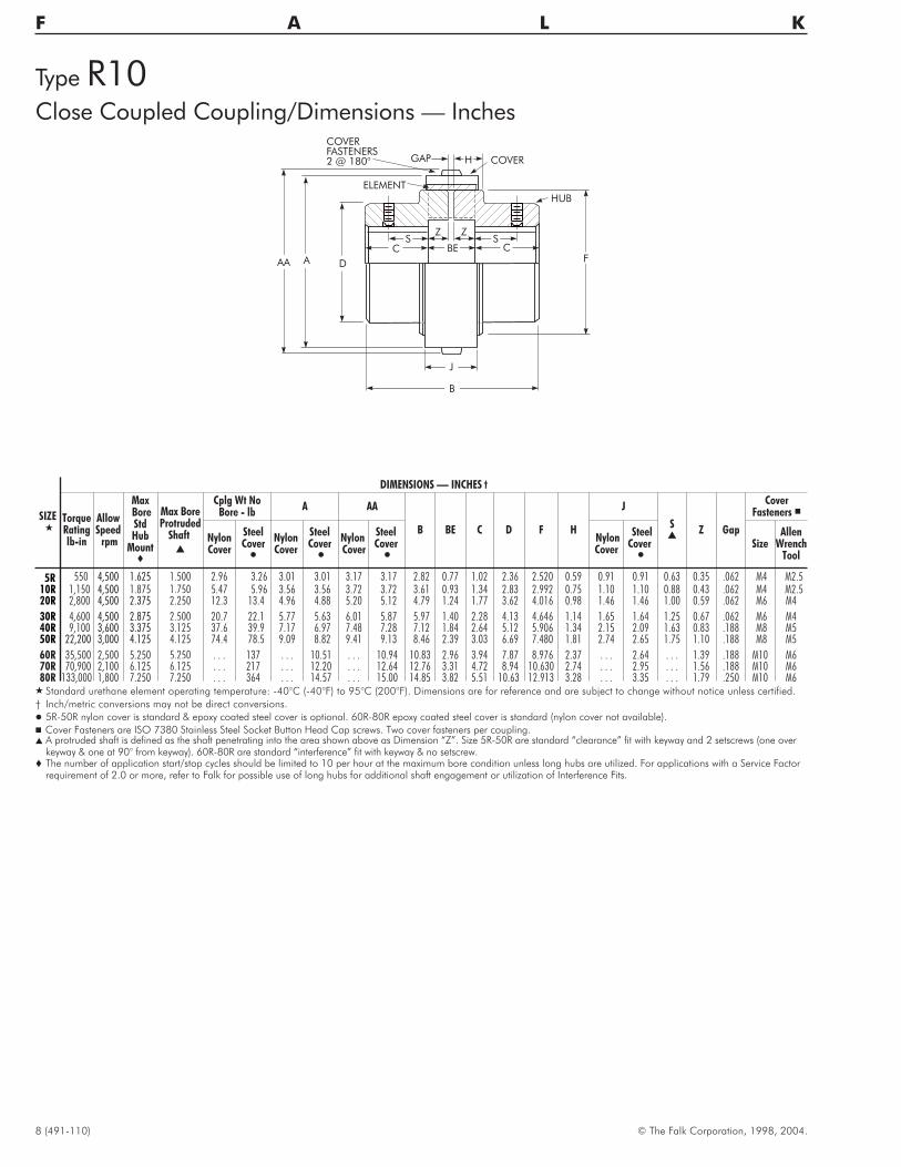
Type R10Close Coupled Coupling/Dimensions — Inches
CF
J
B
AAA D
GAP H
BE
HUB
ELEMENT
COVERFASTENERS2 @ 180° COVER
CS S
Z Z
SIZE�
DIMENSIONS — INCHES †
TorqueRatinglb-in
AllowSpeed
rpm
MaxBoreStdHub
Mount�
Max BoreProtruded
Shaft�
Cplg Wt NoBore - lb
A AA
B BE C D F H
J
S�
Z Gap
CoverFasteners �
NylonCover
SteelCover�
NylonCover
SteelCover�
NylonCover
SteelCover�
NylonCover
SteelCover�
SizeAllen
WrenchTool
5R 550 4,500 1.625 1.500 2.96 3.26 3.01 3.01 3.17 3.17 2.82 0.77 1.02 2.36 2.520 0.59 0.91 0.91 0.63 0.35 .062 M4 M2.510R 1,150 4,500 1.875 1.750 5.47 5.96 3.56 3.56 3.72 3.72 3.61 0.93 1.34 2.83 2.992 0.75 1.10 1.10 0.88 0.43 .062 M4 M2.520R 2,800 4,500 2.375 2.250 12.3 13.4 4.96 4.88 5.20 5.12 4.79 1.24 1.77 3.62 4.016 0.98 1.46 1.46 1.00 0.59 .062 M6 M4
30R 4,600 4,500 2.875 2.500 20.7 22.1 5.77 5.63 6.01 5.87 5.97 1.40 2.28 4.13 4.646 1.14 1.65 1.64 1.25 0.67 .062 M6 M440R 9,100 3,600 3.375 3.125 37.6 39.9 7.17 6.97 7.48 7.28 7.12 1.84 2.64 5.12 5.906 1.34 2.15 2.09 1.63 0.83 .188 M8 M550R 22,200 3,000 4.125 4.125 74.4 78.5 9.09 8.82 9.41 9.13 8.46 2.39 3.03 6.69 7.480 1.81 2.74 2.65 1.75 1.10 .188 M8 M5
60R 35,500 2,500 5.250 5.250 . . . 137 . . . 10.51 . . . 10.94 10.83 2.96 3.94 7.87 8.976 2.37 . . . 2.64 . . . 1.39 .188 M10 M670R 70,900 2,100 6.125 6.125 . . . 217 . . . 12.20 . . . 12.64 12.76 3.31 4.72 8.94 10.630 2.74 . . . 2.95 . . . 1.56 .188 M10 M680R 133,000 1,800 7.250 7.250 . . . 364 . . . 14.57 . . . 15.00 14.85 3.82 5.51 10.63 12.913 3.28 . . . 3.35 . . . 1.79 .250 M10 M6
� Standard urethane element operating temperature: -40°C (-40°F) to 95°C (200°F). Dimensions are for reference and are subject to change without notice unless certified.
† Inch/metric conversions may not be direct conversions.
� 5R-50R nylon cover is standard & epoxy coated steel cover is optional. 60R-80R epoxy coated steel cover is standard (nylon cover not available).
� Cover Fasteners are ISO 7380 Stainless Steel Socket Button Head Cap screws. Two cover fasteners per coupling.� A protruded shaft is defined as the shaft penetrating into the area shown above as Dimension “Z”. Size 5R-50R are standard “clearance” fit with keyway and 2 setscrews (one over
keyway & one at 90° from keyway). 60R-80R are standard “interference” fit with keyway & no setscrew.� The number of application start/stop cycles should be limited to 10 per hour at the maximum bore condition unless long hubs are utilized. For applications with a Service Factor
requirement of 2.0 or more, refer to Falk for possible use of long hubs for additional shaft engagement or utilization of Interference Fits.
© The Falk Corporation, 1998, 2004. (491-110) 9
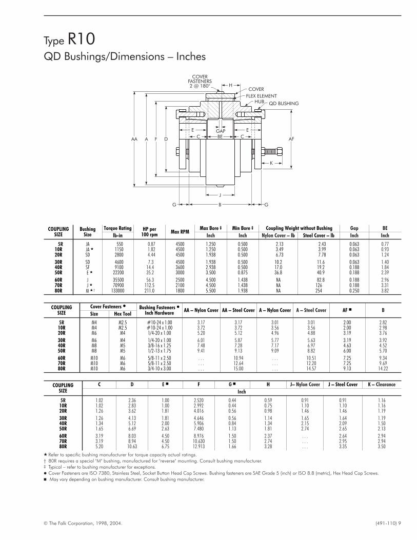
COUPLINGSIZE
Cover Fasteners � Bushing Fasteners �Inch Hardware
AA – Nylon Cover AA – Steel Cover A – Nylon Cover A – Steel Cover AF � BSize Hex Tool
5R M4 M2.5 #10-24 x 1.00 3.17 3.17 3.01 3.01 2.00 2.8210R M4 M2.5 #10-24 x 1.00 3.72 3.72 3.56 3.56 2.00 2.9820R M6 M4 1/4-20 x 1.00 5.20 5.12 4.96 4.88 3.19 3.76
30R M6 M4 1/4-20 x 1.00 6.01 5.87 5.77 5.63 3.19 3.9240R M8 M5 3/8-16 x 1.25 7.48 7.28 7.17 6.97 4.63 4.5250R M8 M5 1/2-13 x 1.75 9.41 9.13 9.09 8.82 6.00 5.70
60R M10 M6 5/8-11 x 2.50 . . . 10.94 . . . 10.51 7.25 9.3470R M10 M6 5/8-11 x 2.50 . . . 12.64 . . . 12.20 7.25 9.6980R M10 M6 3/4-10 x 3.00 . . . 15.00 . . . 14.57 9.13 14.22
COUPLINGSIZE
C D E � F G � H J– Nylon Cover J – Steel Cover K – Clearance
Inch
5R 1.02 2.36 1.00 2.520 0.44 0.59 0.91 0.91 1.1610R 1.02 2.83 1.00 2.992 0.44 0.75 1.10 1.10 1.1620R 1.26 3.62 1.81 4.016 0.56 0.98 1.46 1.46 1.19
30R 1.26 4.13 1.81 4.646 0.56 1.14 1.65 1.64 1.1940R 1.34 5.12 2.00 5.906 0.84 1.34 2.15 2.09 1.5050R 1.65 6.69 2.63 7.480 1.13 1.81 2.74 2.65 2.13
60R 3.19 8.03 4.50 8.976 1.50 2.37 . . . 2.64 2.9470R 3.19 8.94 4.50 10.630 1.50 2.74 . . . 2.95 2.9480R 5.20 10.63 6.75 12.913 1.66 3.28 . . . 3.35 3.50
� Refer to specific bushing manufacturer for torque capacity actual ratings.
† 80R requires a special "M" bushing, manufactured for "reverse" mounting. Consult bushing manufacturer.‡ Typical – refer to bushing manufacturer for exceptions.
� Cover Fasteners are ISO 7380, Stainless Steel, Socket Button Head Cap Screws. Bushing fasteners are SAE Grade 5 (inch) or ISO 8.8 (metric), Hex Head Cap Screws.
� May vary depending on bushing manufacturer. Consult bushing manufacturer.
COUPLINGSIZE
BushingSize
Torque Rating HP per100 rpm
Max RPMMax Bore ‡ Min Bore ‡ Coupling Weight without Bushing Gap BE
lb-in Inch Inch Nylon Cover – lb Steel Cover – lb Inch Inch
5R JA 550 0.87 4500 1.250 0.500 2.13 2.43 0.063 0.7710R JA � 1150 1.82 4500 1.250 0.500 3.49 3.99 0.063 0.9320R SD 2800 4.44 4500 1.938 0.500 6.73 7.78 0.063 1.24
30R SD 4600 7.3 4500 1.938 0.500 10.2 11.6 0.063 1.4040R SF 9100 14.4 3600 2.938 0.500 17.0 19.2 0.188 1.8450R E � 22200 35.2 3000 3.500 0.875 36.8 40.9 0.188 2.39
60R J 35500 56.3 2500 4.500 1.438 NA 82.8 0.188 2.9670R J � 70900 112.5 2100 4.500 1.438 NA 126 0.188 3.3180R M � † 133000 211.0 1800 5.500 1.938 NA 254 0.250 3.82
Type R10QD Bushings/Dimensions – Inches
AFAA A
COVERFASTENERS2 @ 180° H
COVER
FLEX ELEMENTHUB QD BUSHING
E E
CC BE
J
BG G
K
F D
GAP
10 (491-110) © The Falk Corporation, 1998, 2004.
F A L K
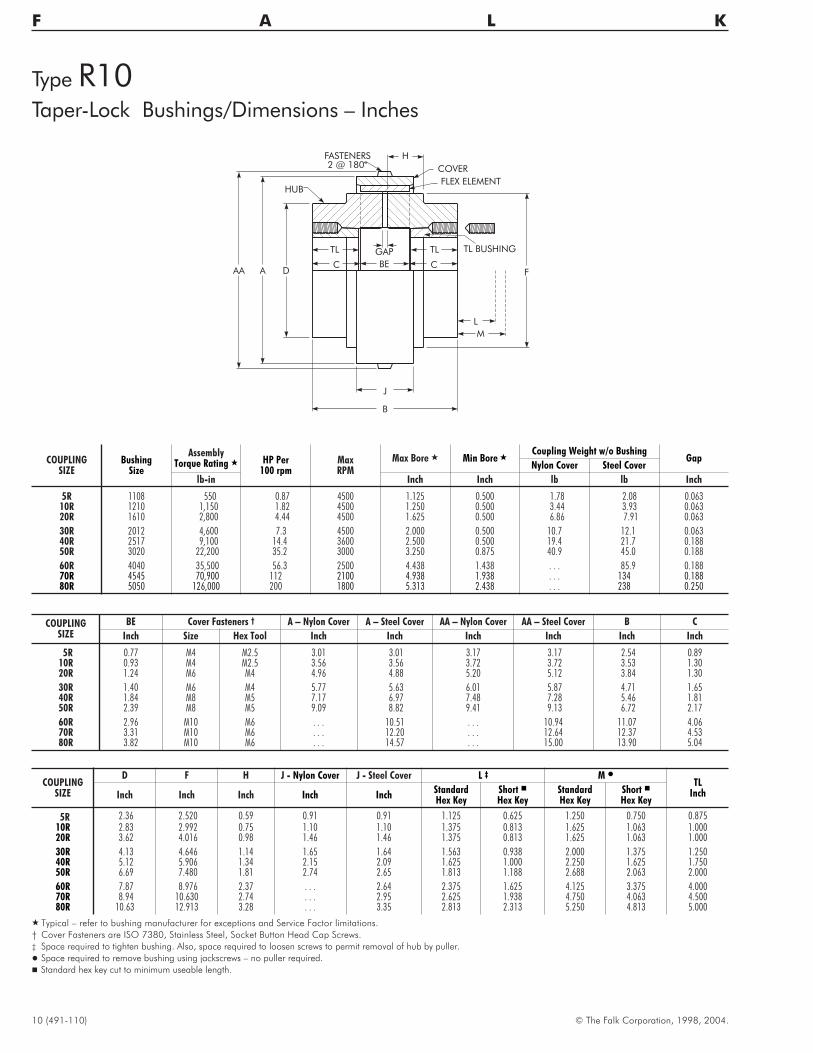
Type R10Taper-Lock Bushings/Dimensions – Inches
AA A
FASTENERS2 @ 180° COVER
FLEX ELEMENT
TL BUSHING
D
J
B
FC BE
GAP
C
H
TL TL
L
M
HUB
COUPLINGSIZE
BE Cover Fasteners † A – Nylon Cover A – Steel Cover AA – Nylon Cover AA – Steel Cover B C
Inch Size Hex Tool Inch Inch Inch Inch Inch Inch
5R 0.77 M4 M2.5 3.01 3.01 3.17 3.17 2.54 0.8910R 0.93 M4 M2.5 3.56 3.56 3.72 3.72 3.53 1.3020R 1.24 M6 M4 4.96 4.88 5.20 5.12 3.84 1.30
30R 1.40 M6 M4 5.77 5.63 6.01 5.87 4.71 1.6540R 1.84 M8 M5 7.17 6.97 7.48 7.28 5.46 1.8150R 2.39 M8 M5 9.09 8.82 9.41 9.13 6.72 2.17
60R 2.96 M10 M6 . . . 10.51 . . . 10.94 11.07 4.0670R 3.31 M10 M6 . . . 12.20 . . . 12.64 12.37 4.5380R 3.82 M10 M6 . . . 14.57 . . . 15.00 13.90 5.04
COUPLINGSIZE
D F H J - Nylon Cover J - Steel Cover L ‡ M �TL
InchInch InchStandardHex Key
Short �Hex Key
StandardHex Key
Short �Hex Key
Inch Inch Inch
5R 2.36 2.520 0.59 0.91 0.91 1.125 0.625 1.250 0.750 0.87510R 2.83 2.992 0.75 1.10 1.10 1.375 0.813 1.625 1.063 1.00020R 3.62 4.016 0.98 1.46 1.46 1.375 0.813 1.625 1.063 1.000
30R 4.13 4.646 1.14 1.65 1.64 1.563 0.938 2.000 1.375 1.25040R 5.12 5.906 1.34 2.15 2.09 1.625 1.000 2.250 1.625 1.75050R 6.69 7.480 1.81 2.74 2.65 1.813 1.188 2.688 2.063 2.000
60R 7.87 8.976 2.37 . . . 2.64 2.375 1.625 4.125 3.375 4.00070R 8.94 10.630 2.74 . . . 2.95 2.625 1.938 4.750 4.063 4.50080R 10.63 12.913 3.28 . . . 3.35 2.813 2.313 5.250 4.813 5.000
� Typical – refer to bushing manufacturer for exceptions and Service Factor limitations.
† Cover Fasteners are ISO 7380, Stainless Steel, Socket Button Head Cap Screws.
‡ Space required to tighten bushing. Also, space required to loosen screws to permit removal of hub by puller.
� Space required to remove bushing using jackscrews – no puller required.
� Standard hex key cut to minimum useable length.
COUPLINGSIZE
BushingSize
AssemblyTorque Rating � HP Per
100 rpmMaxRPM
Max Bore � Min Bore �Coupling Weight w/o Bushing
GapNylon Cover Steel Cover
lb-in Inch Inch lb lb Inch
5R 1108 550 0.87 4500 1.125 0.500 1.78 2.08 0.06310R 1210 1,150 1.82 4500 1.250 0.500 3.44 3.93 0.06320R 1610 2,800 4.44 4500 1.625 0.500 6.86 7.91 0.063
30R 2012 4,600 7.3 4500 2.000 0.500 10.7 12.1 0.06340R 2517 9,100 14.4 3600 2.500 0.500 19.4 21.7 0.18850R 3020 22,200 35.2 3000 3.250 0.875 40.9 45.0 0.188
60R 4040 35,500 56.3 2500 4.438 1.438 . . . 85.9 0.18870R 4545 70,900 112 2100 4.938 1.938 . . . 134 0.18880R 5050 126,000 200 1800 5.313 2.438 . . . 238 0.250
© The Falk Corporation, 1998, 2004. (491-110) 11
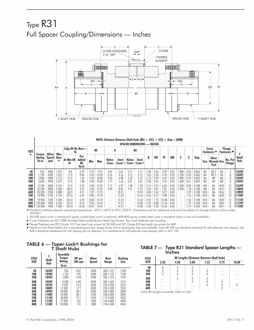
SPACER HUBT SHAFT HUB
COVER FASTENERS2 @ 180º
COVER
FLEXIBLEELEMENT
T SHAFT HUB
FFDDS
GAPSS
B
SPACER HUB
B BB BBE
GAP
CC
AAA
Z ZRM RM
SIZE�
NOTE: Distance Between Shaft Ends (BE) = 2(C) + 2(Z) + Gap – 2(RM)
SPACER DIMENSIONS — INCHES
TorqueRatinglb-in
AllowSpeedrpm
MaxBore�
Cplg Wt No Bore –lb
BE A AA
B DD FF RM S Z Gap
CoverFasteners �
FlangeFasteners �
TShaftHubAt Min BE
lb
PerAdded
BElb/in
Min MaxNylonCover
SteelCover †
NylonCover
SteelCover † Size
AllenWrench
ToolSize
No. PerFlange
5R 550 4500 1.375 8.0 0.79 3.19 9.25 3.01 3.01 3.17 3.17 1.38 2.06 3.39 0.05 1.080 0.35 0.062 M4 M2.5 M6 4 1020T10R 1,150 4500 1.625 11.0 0.86 3.50 10.00 3.56 3.56 3.72 3.72 1.63 2.34 3.70 0.05 1.240 0.43 0.062 M4 M2.5 M6 8 1030T20R 2,800 4500 2.125 21.0 1.49 3.50 10.00 4.96 4.88 5.20 5.12 2.13 3.09 4.45 0.05 1.080 0.59 0.062 M6 M4 M6 8 1040T30R 4,600 4500 2.375 31.0 1.88 4.38 10.00 5.77 5.63 6.01 5.87 2.38 3.44 4.96 0.05 1.600 0.67 0.062 M6 M4 M8 8 1050T
40R 9,100 3600 3.125 57.0 2.23 5.00 12.25 7.17 6.97 7.48 7.28 3.13 4.31 6.02 0.05 1.840 0.83 0.188 M8 M5 M10 12 1070T50R 22,200 3000 3.500 100.0 3.31 6.50 12.25 9.09 8.82 9.41 9.13 3.50 4.81 7.01 0.05 1.960 1.10 0.188 M8 M5 M12 12 1080T60R 35,500 2500 4.000 160.0 4.57 7.87 12.25 . . . 10.51 . . . 10.94 4.00 5.63 8.27 0.05 . . . 1.39 0.188 M10 M6 M16 12 1090T70R 70,900 2100 4.750 225.0 6.59 8.80 14.70 . . . 12.20 . . . 12.64 3.56 6.75 9.88 0.06 . . . 1.56 0.188 M10 M6 M20 12 1100T
70R 70,900 2100 5.500 265.0 6.59 8.80 14.70 . . . 12.20 . . . 12.64 4.10 7.75 10.88 0.06 . . . 1.56 0.188 M10 M6 M20 12 1110T80R 133,000 1800 6.250 415.0 8.10 9.85 16.69 . . . 14.57 . . . 15.00 4.70 8.88 12.56 0.06 . . . 1.79 0.250 M10 M6 M24 12 1120T80R 133,000 1800 7.000 505.0 13.60 10.07 16.69 . . . 14.57 . . . 15.00 5.30 9.38 13.63 0.06 . . . 1.79 0.250 M10 M6 M27 12 1130T
� Standard urethane element operating temperature: -40°C (-40°F) to 95°C (200°F). Dimensions are for reference only and are subject to change without notice unlesscertified.)
† 5R-50R nylon cover is standard & epoxy coated steel cover is optional. 60R-80R epoxy coated steel cover is standard (nylon cover not available.)
� Cover Fasteners are ISO 7380 Stainless Steel Socket Button Head Cap Screws. Two cover fasteners per coupling.
� Flange Fasteners are ISO Grade 10.9 hex head cap screws for 5R-50R and ISO Grade 8.8 hex head cap screws for 60R.� Maximum Inch Bore listed is for a standard square key. Larger bores, with a rectangular key, are available. Sizes 5R-50R are standard clearance fit with setscrew over keyway. Size
60R is standard interference fit with keyway, but no setscrew. For interference fit with setscrew over keyway, refer to 427-105.
TABLE 6 — Taper-Lock® Bushings forT Shaft Hubs
CPLGSIZE
TShaftHub
AssemblyTorqueRating
HP per100 rpm
AllowSpeed
BoreRange
BushingSize
lb-in
5R 1020T 550 0.87 4500 .500-1.125 110810R 1030T 1,150 1.82 4500 .500-1.125 110820R 1040T 2,800 4.44 4500 .500-1.375 1310
30R 1050T 4,300 6.82 4500 .500-1.625 161540R 1070T 9,100 14.4 3600 .750-2.500 252550R 1080T 11,300 17.9 3000 .750-2.500 252560R 1090T 24,000 38.1 2500 .938-3.000 303070R 1100T 24,000 38.1 2100 .938-3.000 303070R 1110T 44,000 71.1 2100 1.19-3.500 353580R 1120T 77,300 122 1800 1.44-4.000 404080R 1130T 110,000 174 1800 1.94-4.500 4545
TABLE 7 — Type R31 Standard Spacer Lengths —Inches
CPLGSIZE
BE Lengths (Distance Between Shaft Ends)
3.50 4.38 5.00 7.25 9.75 10.00
5R X X X . . . . . . . . .10R X X X X . . . . . .20R X X X X . . . . . .
30R . . . X X X . . . . . .40R . . . . . . X X X . . .50R . . . . . . . . . X X X60R . . . . . . . . . . . . X . . .
Other BE lengths available. Refer to Falk.
Type R31Full Spacer Coupling/Dimensions — Inches
12 (491-110) © The Falk Corporation, 1998, 2004.
F A L K
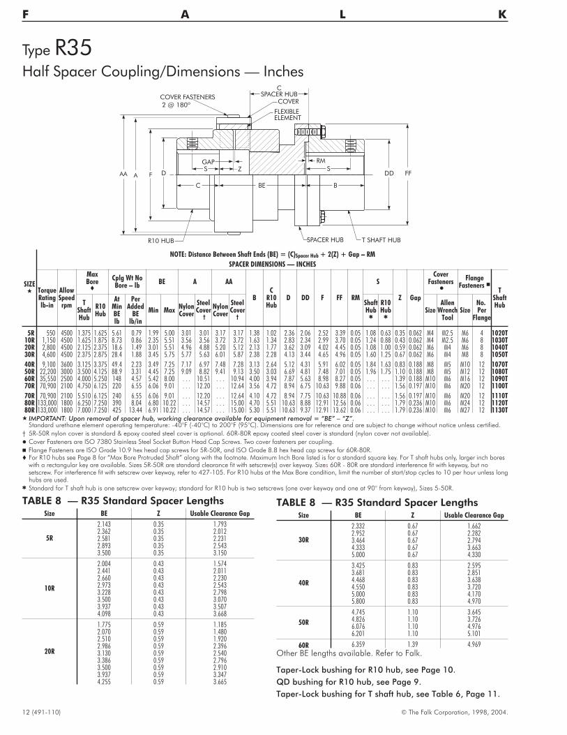
Type R35Half Spacer Coupling/Dimensions — Inches
COVER FASTENERS2 @ 180º
COVER
FLEXIBLEELEMENT
T SHAFT HUB
FFDDGAP
B
SPACER HUB
BB
CSPACER HUB
AA ASS
BE BC
ZGAP
F D
R10 HUB
RM
SIZE�
NOTE: Distance Between Shaft Ends (BE) = (C)Spacer Hub + 2(Z) + Gap – RM
SPACER DIMENSIONS — INCHES
TorqueRatinglb-in
AllowSpeedrpm
MaxBore�
Cplg Wt NoBore – lb
BE A AA
BC
R10Hub
D DD F FF RM
S
Z Gap
CoverFasteners
�
FlangeFasteners �
TShaftHubT
ShaftHub
R10Hub
AtMinBElb
PerAdded
BElb/in
Min MaxNylonCover
SteelCover
†
NylonCover
SteelCover
†
ShaftHub
�
R10Hub
�
SizeAllen
WrenchTool
SizeNo.Per
Flange
5R 550 4500 1.375 1.625 5.61 0.79 1.99 5.00 3.01 3.01 3.17 3.17 1.38 1.02 2.36 2.06 2.52 3.39 0.05 1.08 0.63 0.35 0.062 M4 M2.5 M6 4 1020T10R 1,150 4500 1.625 1.875 8.73 0.86 2.35 5.51 3.56 3.56 3.72 3.72 1.63 1.34 2.83 2.34 2.99 3.70 0.05 1.24 0.88 0.43 0.062 M4 M2.5 M6 8 1030T20R 2,800 4500 2.125 2.375 18.6 1.49 3.01 5.51 4.96 4.88 5.20 5.12 2.13 1.77 3.62 3.09 4.02 4.45 0.05 1.08 1.00 0.59 0.062 M6 M4 M6 8 1040T30R 4,600 4500 2.375 2.875 28.4 1.88 3.45 5.75 5.77 5.63 6.01 5.87 2.38 2.28 4.13 3.44 4.65 4.96 0.05 1.60 1.25 0.67 0.062 M6 M4 M8 8 1050T
40R 9,100 3600 3.125 3.375 49.4 2.23 3.49 7.25 7.17 6.97 7.48 7.28 3.13 2.64 5.12 4.31 5.91 6.02 0.05 1.84 1.63 0.83 0.188 M8 M5 M10 12 1070T50R 22,200 3000 3.500 4.125 88.9 3.31 4.45 7.25 9.09 8.82 9.41 9.13 3.50 3.03 6.69 4.81 7.48 7.01 0.05 1.96 1.75 1.10 0.188 M8 M5 M12 12 1080T60R 35,550 2500 4.000 5.250 148 4.57 5.42 8.00 . . . 10.51 . . . 10.94 4.00 3.94 7.87 5.63 8.98 8.27 0.05 . . . . . . 1.39 0.188 M10 M6 M16 12 1090T70R 70,900 2100 4.750 6.125 220 6.55 6.06 9.01 . . . 12.20 . . . 12.64 3.56 4.72 8.94 6.75 10.63 9.88 0.06 . . . . . . 1.56 0.197 M10 M6 M20 12 1100T
70R 70,900 2100 5.510 6.125 240 6.55 6.06 9.01 . . . 12.20 . . . 12.64 4.10 4.72 8.94 7.75 10.63 10.88 0.06 . . . . . . 1.56 0.197 M10 M6 M20 12 1110T80R 133,000 1800 6.250 7.250 390 8.04 6.80 10.22 . . . 14.57 . . . 15.00 4.70 5.51 10.63 8.88 12.91 12.56 0.06 . . . . . . 1.79 0.236 M10 M6 M24 12 1120T80R 133,000 1800 7.000 7.250 425 13.44 6.91 10.22 . . . 14.57 . . . 15.00 5.30 5.51 10.63 9.37 12.91 13.62 0.06 . . . . . . 1.79 0.236 M10 M6 M27 12 1130T
� IMPORTANT: Upon removal of spacer hub, working clearance available for equipment removal = “BE” – “Z”.Standard urethane element operating temperature: -40°F (-40°C) to 200°F (95°C). Dimensions are for reference and are subject to change without notice unless certified.
† 5R-50R nylon cover is standard & epoxy coated steel cover is optional. 60R-80R epoxy coated steel cover is standard (nylon cover not available).
� Cover Fasteners are ISO 7380 Stainless Steel Socket Button Head Cap Screws. Two cover fasteners per coupling.
� Flange Fasteners are ISO Grade 10.9 hex head cap screws for 5R-50R, and ISO Grade 8.8 hex head cap screws for 60R-80R.� For R10 hubs see Page 8 for “Max Bore Protruded Shaft” along with the footnote. Maximum Inch Bore listed is for a standard square key. For T shaft hubs only, larger inch bores
with a rectangular key are available. Sizes 5R-50R are standard clearance fit with setscrew(s) over keyway. Sizes 60R - 80R are standard interference fit with keyway, but nosetscrew. For interference fit with setscrew over keyway, refer to 427-105. For R10 hubs at the Max Bore condition, limit the number of start/stop cycles to 10 per hour unless longhubs are used.
� Standard for T shaft hub is one setscrew over keyway; standard for R10 hub is two setscrews (one over keyway and one at 90° from keyway), Sizes 5-50R.
Taper-Lock bushing for R10 hub, see Page 10.
QD bushing for R10 hub, see Page 9.
Taper-Lock bushing for T shaft hub, see Table 6, Page 11.
TABLE 8 — R35 Standard Spacer LengthsSize BE Z Usable Clearance Gap
5R
2.143 0.35 1.7932.362 0.35 2.0122.581 0.35 2.2312.893 0.35 2.5433.500 0.35 3.150
10R
2.004 0.43 1.5742.441 0.43 2.0112.660 0.43 2.2302.973 0.43 2.5433.228 0.43 2.7983.500 0.43 3.0703.937 0.43 3.5074.098 0.43 3.668
20R
1.775 0.59 1.1852.070 0.59 1.4802.510 0.59 1.9202.986 0.59 2.3963.130 0.59 2.5403.386 0.59 2.7963.500 0.59 2.9103.937 0.59 3.3474.255 0.59 3.665
TABLE 8 — R35 Standard Spacer LengthsSize BE Z Usable Clearance Gap
30R
2.332 0.67 1.6622.952 0.67 2.2823.464 0.67 2.7944.333 0.67 3.6635.000 0.67 4.330
40R
3.425 0.83 2.5953.681 0.83 2.8514.468 0.83 3.6384.550 0.83 3.7205.000 0.83 4.1705.800 0.83 4.970
50R
4.745 1.10 3.6454.826 1.10 3.7266.076 1.10 4.9766.201 1.10 5.101
60R 6.359 1.39 4.969
Other BE lengths available. Refer to Falk.
© The Falk Corporation, 1998, 2004. (491-110) 13
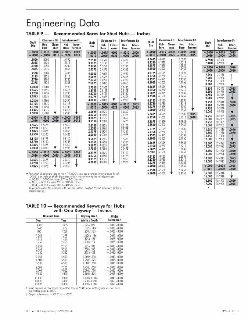
Engineering DataTABLE 9 — Recommended Bores for Steel Hubs — Inches
ShaftDia
Clearance Fit Interference Fit
HubBore
Clear-ance
HubBore
Inter-ference
+.0000 +.0010 .0000 +.0005 .0000– .0005 – .0000 .0015 – .0000 .0010
.5000 .5000 .4990
.5625 .5625 .5615
.6250 .6250 .6240
.6875 .6875 .6865
.7500 .7500 .7490
.8125 .8125 .8115
.8750 .8750 .8740
.9375 .9375 .9365
1.0000 1.0000 .99901.0625 1.0625 1.06151.1250 1.1250 1.12401.1875 1.1875 1.1865
1.2500 1.2500 1.24901.3125 1.3125 1.31151.3750 1.3750 1.37401.4375 1.4375 1.43651.5000 1.5000 1.4990
+.0000 +.0010 .0000 +.0005 .0000– .0010 – .0000 .0020 – .0000 .0015
1.5625 1.5625 1.56101.6250 1.6250 1.62351.6875 1.6875 1.68601.7500 1.7500 1.7485
1.8125 1.8125 1.81101.8750 1.8750 1.87351.9375 1.9375 1.93602.0000 2.0000 1.9985
+.0000 +.0015 .0000 +.0005 .0000– .0010 – .0000 .0025 – .0000 .0015
2.0625 2.0625 2.06102.1250 2.1250 2.12352.1875 2.1875 2.1860
ShaftDia
Clearance Fit Interference Fit
HubBore
Clear-ance
HubBore
Inter-ference
+.0000 +.0015 .0000 +.0010 .0000– .0010 – .0000 .0025 – .0000 .0020
2.2500 2.2500 2.24803.3125 2.3125 2.31052.3750 2.3750 2.37302.4375 2.4375 2.4355
2.5000 2.5000 2.49802.5625 2.5625 2.56052.6250 2.6250 2.62302.6875 2.6875 2.6855
2.7500 2.7500 2.74802.8125 2.8125 2.81052.8750 2.8750 2.87302.9375 2.9375 2.93553.0000 3.0000 2.9980
+.0000 +.0015 .0000 +.0010 .0005– .0010 – .0000 .0025 – .0000 .0025
3.0625 3.0625 3.06003.1250 3.1250 3.12253.1875 3.1875 3.18503.2500 3.2500 3.2475
3.3125 3.3125 3.31003.3750 3.3750 3.37253.4375 3.4375 3.43503.5000 3.5000 3.4975
3.5625 3.5625 3.56003.6250 3.6250 3.62253.6875 3.6875 3.68503.7500 3.7500 3.7475
3.8125 3.8125 3.81003.8750 3.8750 3.87253.9375 3.9375 3.93504.0000 4.0000 3.9975
ShaftDia
Interference Fit
HubBore
Inter-ference
+.0000 +.0015 .0015– .0010 – .0000 .0040
6.7500 6.74607.0000 6.9960
+.0000 +.0020 .0020– .0010 – .0000 .0050
7.250 7.24507.500 7.49507.750 7.74508.000 7.9950
8.250 8.2445 .00258.500 8.4945 .00558.750 8.74459.000 8.9945
9.250 9.2440 .00309.500 9.4940 .00609.750 9.7440
10.000 9.9940
10.250 10.2435 .003510.500 10.4935 .006510.750 10.743511.000 10.9935
11.250 11.2430 .004011.500 11.4930 .007011.750 11.743012.000 11.9930
12.500 12.4925 .004513.000 12.9925 .0075
13.500 13.4920 .005014.000 13.9920 .0080
14.500 14.4915 .005515.000 14.9915 .0085
+.000 +.0025 .0055– .001 – .0000 .0090
15.500 15.491016.000 15.9910
16.500 16.4905 .006017.000 16.9905 .0095
�
ShaftDia
Clearance Fit Interference Fit
HubBore
Clear-ance
HubBore
Inter-ference
+.0000 +.0015 .0000 +.0015 .0010– .0010 – .0000 .0025 – .0000 .0035
4.0625 4.0625 4.05904.1250 4.1250 4.12154.1875 4.1875 4.18404.2500 4.2500 4.2465
4.3125 4.3125 4.30904.3750 4.3750 4.37154.4375 4.4375 4.43404.5000 4.5000 4.4965
4.5625 4.5625 4.55904.6250 4.6250 4.62154.6875 4.6875 4.68404.7500 4.7500 4.7465
4.8125 4.8125 4.80904.8750 4.8750 4.87154.9375 4.9375 4.93405.0000 5.0000 4.9965
5.0625 5.0625 5.0585 .00155.1250 5.1250 5.1210 .0040
5.1875 5.1875 5.18355.2500 5.2500 5.2460
5.3125 5.3125 5.30855.3750 5.3750 5.37105.4375 5.4375 5.43355.5000 5.5000 5.4960
5.5625 5.5625 5.55855.6250 5.6250 5.62105.6875 5.6875 5.683557500 5.7500 5.7460
5.8125 5.8125 5.80855.8750 5.8750 5.87105.9375 5.9375 5.93356.0000 6.0000 5.9960
6.2500 6.2500 6.24606.5000 6.5000 6.4960� For shaft diameters larger than 17.000", use an average interference fit of
.0005" per inch of shaft diameter within the following bore tolerances:+.0025, –.0000 for over 17" to 20" dia. incl.+.003, –.000 for over 20" to 30" dia. incl.+.004, –.000 for over 30" to 40" dia. incl.Tolerances and fits comply with, or are within, AGMA 9002 standard (Class 1clearance fit).
TABLE 10 — Recommended Keyways for Hubswith One Keyway — Inches
Nominal Bore Keyway Size ‡ WidthTolerance †Over Thru Width x Depth
.4375 .5625 .125 x .062 +.0020 -.0000
.5625 .875 .1875 x .094 +.0020 -.0000.875 1.250 .250 x .125 +.0020 -.0000
1.250 1.375 .3125 x .156 +.0020 -.00001.375 1.750 .375 x .188 +.0025 -.00001.750 2.250 .500 x .250 +.0025 -.0000
2.250 2.750 .625 x .312 +.0030 -.00002.750 3.250 .750 x .375 +.0030 -.00003.250 3.750 .875 x .438 +.0030 -.0000
3.750 4.500 1.000 x .500 +.0030 -.00004.500 5.500 1.250 x .625 +.0035 -.00005.500 6.500 1.500 x .750 +.0035 -.0000
6.500 7.500 1.750 x .750 +.0040 -.00007.500 9.000 2.000 x .750 +.0040 -.00009.000 11.000 2.500 x .875 +.0045 -.0000
11.000 13.000 3.000 x 1.000 +.0045 -.000013.000 15.000 3.500 x 1.250 +.0050 -.000015.000 18.000 4.000 x 1.500 +.0050 -.0000
‡ One square key for bore diameters thru 6.500"; one rectangular key for borediameters over 6.500".
† Depth tolerance: +.010" to +.020".
14 (491-110) © The Falk Corporation, 1998, 2004.
F A L K
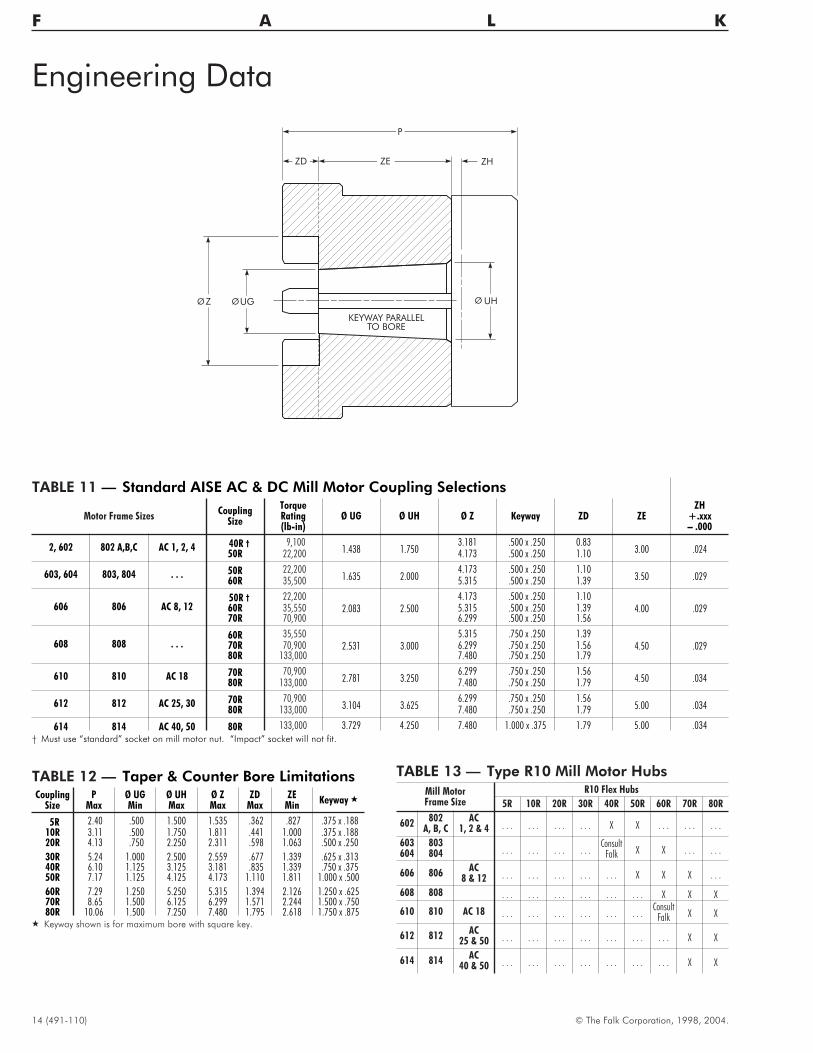
ZH
P
ZEZD
Z UG UH
KEYWAY PARALLELTO BORE
TABLE 12 — Taper & Counter Bore LimitationsCoupling
SizeP
MaxØ UGMin
Ø UHMax
Ø ZMax
ZDMax
ZEMin
Keyway �
5R 2.40 .500 1.500 1.535 .362 .827 .375 x .18810R 3.11 .500 1.750 1.811 .441 1.000 .375 x .18820R 4.13 .750 2.250 2.311 .598 1.063 .500 x .250
30R 5.24 1.000 2.500 2.559 .677 1.339 .625 x .31340R 6.10 1.125 3.125 3.181 .835 1.339 .750 x .37550R 7.17 1.125 4.125 4.173 1.110 1.811 1.000 x .500
60R 7.29 1.250 5.250 5.315 1.394 2.126 1.250 x .62570R 8.65 1.500 6.125 6.299 1.571 2.244 1.500 x .75080R 10.06 1.500 7.250 7.480 1.795 2.618 1.750 x .875
� Keyway shown is for maximum bore with square key.
TABLE 11 — Standard AISE AC & DC Mill Motor Coupling Selections
Motor Frame SizesCoupling
Size
TorqueRating(lb-in)
Ø UG Ø UH Ø Z Keyway ZD ZEZH
+.xxx– .000
2, 602 802 A,B,C AC 1, 2, 4 40R † 9,1001.438 1.750
3.181 .500 x .250 0.833.00 .02450R 22,200 4.173 .500 x .250 1.10
603, 604 803, 804 . . . 50R 22,2001.635 2.000
4.173 .500 x .250 1.103.50 .02960R 35,500 5.315 .500 x .250 1.39
606 806 AC 8, 1250R † 22,200
2.083 2.5004.173 .500 x .250 1.10
4.00 .02960R 35,550 5.315 .500 x .250 1.3970R 70,900 6.299 .500 x .250 1.56
608 808 . . .60R 35,550
2.531 3.0005.315 .750 x .250 1.39
4.50 .02970R 70,900 6.299 .750 x .250 1.5680R 133,000 7.480 .750 x .250 1.79
610 810 AC 18 70R 70,9002.781 3.250
6.299 .750 x .250 1.564.50 .03480R 133,000 7.480 .750 x .250 1.79
612 812 AC 25, 30 70R 70,9003.104 3.625
6.299 .750 x .250 1.565.00 .03480R 133,000 7.480 .750 x .250 1.79
614 814 AC 40, 50 80R 133,000 3.729 4.250 7.480 1.000 x .375 1.79 5.00 .034
† Must use “standard” socket on mill motor nut. “Impact” socket will not fit.
Engineering Data
TABLE 13 — Type R10 Mill Motor Hubs
Mill MotorFrame Size
R10 Flex Hubs
5R 10R 20R 30R 40R 50R 60R 70R 80R
602802
A, B, CAC
1, 2 & 4 . . . . . . . . . . . . X X . . . . . . . . .
603604
803804 . . . . . . . . . . . .
ConsultFalk X X . . . . . .
606 806AC
8 & 12 . . . . . . . . . . . . . . . X X X . . .
608 808 . . . . . . . . . . . . . . . . . . X X X
610 810 AC 18 . . . . . . . . . . . . . . . . . .Consult
Falk X X
612 812AC
25 & 50 . . . . . . . . . . . . . . . . . . . . . X X
614 814AC
40 & 50 . . . . . . . . . . . . . . . . . . . . . X X
© The Falk Corporation, 1998, 2004. (491-110) 15
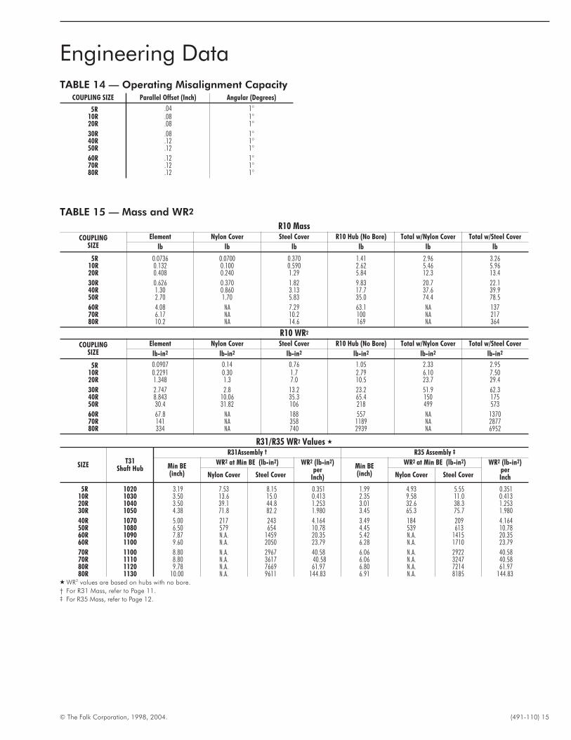
TABLE 14 — Operating Misalignment CapacityCOUPLING SIZE Parallel Offset (Inch) Angular (Degrees)
5R .04 1°10R .08 1°20R .08 1°
30R .08 1°40R .12 1°50R .12 1°
60R .12 1°70R .12 1°80R .12 1°
Engineering Data
TABLE 15 — Mass and WR2
R10 MassCOUPLING
SIZEElement Nylon Cover Steel Cover R10 Hub (No Bore) Total w/Nylon Cover Total w/Steel Cover
lb lb lb lb lb lb
5R 0.0736 0.0700 0.370 1.41 2.96 3.2610R 0.132 0.100 0.590 2.62 5.46 5.9620R 0.408 0.240 1.29 5.84 12.3 13.4
30R 0.626 0.370 1.82 9.83 20.7 22.140R 1.30 0.860 3.13 17.7 37.6 39.950R 2.70 1.70 5.83 35.0 74.4 78.5
60R 4.08 NA 7.29 63.1 NA 13770R 6.17 NA 10.2 100 NA 21780R 10.2 NA 14.6 169 NA 364
R10 WR2
COUPLINGSIZE
Element Nylon Cover Steel Cover R10 Hub (No Bore) Total w/Nylon Cover Total w/Steel Cover
lb-in2 lb-in2 lb-in2 lb-in2 lb-in2 lb-in2
5R 0.0907 0.14 0.76 1.05 2.33 2.9510R 0.2291 0.30 1.7 2.79 6.10 7.5020R 1.348 1.3 7.0 10.5 23.7 29.4
30R 2.747 2.8 13.2 23.2 51.9 62.340R 8.843 10.06 35.3 65.4 150 17550R 30.4 31.82 106 218 499 573
60R 67.8 NA 188 557 NA 137070R 141 NA 358 1189 NA 287780R 334 NA 740 2939 NA 6952
R31/R35 WR2 Values �
SIZET31
Shaft Hub
R31Assembly † R35 Assembly ‡
Min BE(inch)
WR2 at Min BE (lb-in2) WR2 (lb-in2)per
Inch)
Min BE(inch)
WR2 at Min BE (lb-in2) WR2 (lb-in2)perInchNylon Cover Steel Cover Nylon Cover Steel Cover
5R 1020 3.19 7.53 8.15 0.351 1.99 4.93 5.55 0.35110R 1030 3.50 13.6 15.0 0.413 2.35 9.58 11.0 0.41320R 1040 3.50 39.1 44.8 1.253 3.01 32.6 38.3 1.25330R 1050 4.38 71.8 82.2 1.980 3.45 65.3 75.7 1.980
40R 1070 5.00 217 243 4.164 3.49 184 209 4.16450R 1080 6.50 579 654 10.78 4.45 539 613 10.7860R 1090 7.87 N.A. 1459 20.35 5.42 N.A. 1415 20.3560R 1100 9.60 N.A. 2050 23.79 6.28 N.A. 1710 23.79
70R 1100 8.80 N.A. 2967 40.58 6.06 N.A. 2922 40.5870R 1110 8.80 N.A. 3617 40.58 6.06 N.A. 3247 40.5880R 1120 9.78 N.A. 7669 61.97 6.80 N.A. 7214 61.9780R 1130 10.00 N.A. 9611 144.83 6.91 N.A. 8185 144.83
� WR2 values are based on hubs with no bore.
† For R31 Mass, refer to Page 11.‡ For R35 Mass, refer to Page 12.

THE FALK CORPORATION
Plant Locations
Global Sales Offices
United States
Main
P.O. Box 492 Zip 53201-04923001 W. Canal StreetZip 53208-4200
Milwaukee, WI USAPhone: 1-800-852-FALK (3255) or414-342-3131FAX: 414-937-4359E-mail: [email protected]: www.falkcorp.com
Falk Capitol Drive12001 West Capitol DriveMilwaukee, WI 53222-1003414-438-3031FAX: 414-438-3049
Falk Auburn1600 Pumphrey Ave.Auburn, AL 36832334-321-9120FAX: 334-821-9103
Falk Renew1903 South Moorland BlvdNew Berlin, WI 53151262-317-1420FAX: 262-317-1428
Falk Australia Pty.34-36 Broadmeadow RdBroadmeadow, NSW 229461-2-4962-8000FAX: 61-2-4962-8001
Atlanta, GA334-728-0747
Baltimore, MD717-993-0601
Birmingham, AL205-661-3933
Charleston, WV304-595-1394
Charlotte, NC704-531-9250
Chicago, IL847-677-6492
Cincinnati, OH513-563-9699
Cleveland, OH330-528-1557
Dallas, TX469-556-7313
Denver, CO303-980-5131
Detroit, MI248-969-2553
Houston, TX281-477-9570
Kansas City, KS913-685-3254
Memphis, TN901-309-0340
Miami, FL954-436-6055
Milwaukee, WI262-646-4346
Minneapolis, MN763-522-0994
New Orleans, LA504-832-1448
Northeast860-355-0478
Northwest360-546-3411
Omaha, NE402-896-4520
Phoenix, AZ480-460-7188
Pittsburgh, PA412-563-1754
Rochester, NY585-223-5205
St. Louis, MO636-256-7600
Salt Lake City, UT801-268-4419
Tampa, FL941-358-1045
Victorville, CA760-401-0749
Calgary, AB403-225-6630
Montreal, PQ450-424-7100
Toronto, ON416-674-0346
Vancouver, BC604-946-8506
Mexico, D.F.52-5-333-2500
Santiago, Chile56-2-231-5647
Sao Paulo, Brazil55-11-882-1000
Canada
Latin America
Europe
Asia/Pacific
Distribution Centers
Brighouse, United Kingdom44-1484-401872
Korea82-42-603-5644
Newcastle, Australia61-2-4962-8000
Perth, Australia61-8-9414-7800
Shanghai, China86-21-6219-6847
Singapore65-444-0388
Taiwan886-7-556-0263
Auburn, ALPH 334-821-9100FAX 414-937-4003
Doncaster, United KingdomPH 44-1484-401872FAX 44-1484-401341
Milwaukee, WIPH 414-342-3131FAX 414-937-4359
Sacramento, CAPH 877-937-6744FAX 414-937-4444
Toronto, ONPH 416-675-6071FAX 416-213-1020
South Africa
Gauteng, SA27-11-422-2496