Tailgates By THIEMAN M16, 20 MLB16, 20 OWNERS MANUAL/PARTS … … · stow away tailgates by...
24
S TOW A WAY Tailgates By THIEMAN M16, 20 MLB16, 20 OWNERS MANUAL/PARTS LIST IMPORTANT! KEEP IN VEHICLE! ! PLEASE READ AND UNDERSTAND THE CONTENTS OF THIS MANUAL BEFORE OPERATING THE EQUIPMENT. TAILGATES, INC. 600 East Wayne Street Celina, Ohio 45822 Phone: 419-586-7727 Fax: 419-586-9724 M-25 SHOWN NTEA THE ASSOCIATION FOR THE WORK TRUCK INDUSTRY TM M E M B E R
Transcript of Tailgates By THIEMAN M16, 20 MLB16, 20 OWNERS MANUAL/PARTS … … · stow away tailgates by...
STOWAWAYTailgates By THIEMAN
M16, 20 MLB16, 20OWNERS MANUAL/PARTS LIST
IMPORTANT! KEEP IN VEHICLE!!PLEASE READ AND UNDERSTAND THE CONTENTS OF THIS
MANUAL BEFORE OPERATING THE EQUIPMENT.
TAILGATES, INC.600 East Wayne StreetCelina, Ohio 45822
Phone: 419-586-7727 Fax: 419-586-9724
M-25 SHOWN
NTEAT H E A S S O C I A T I O N F O R T H E W O R K T R U C K I N D U S T R Y
TM
M E M B E R
TABLE OF CONTENTS
WARNINGS.........................................................................................2
PARTS ORDERING PROCEDURE ....................................................3
OPERATING INSTRUCTIONS............................................................5
MAINTENANCE GUIDE......................................................................5
SEMI-ANNUAL INSPECTION .............................................................6
ELECTRICAL PICTORIALS ................................................................7
INSPECTION AND LOCATION OF DECALS......................................8
PLATFORM ASM ....................................................................9 thru 12
SPACER ASM ...................................................................................13
TRUNNION, LIFT ARM, AND IDLER ARM ASM...............................14
PUMP ASM ELECTRIC CONTROL POWER DOWN .......................15
PUMP ASM ELECTRIC CONTROL GRAVITY DOWN .....................16
PUMP PARTS ...........................................................................17 & 18
SNUBBER KIT ..................................................................................19
TROUBLESHOOTING GUIDE..............................................20 thru 23
FOR YOUR RECORDSModel No. __________________________ Date Purchased _______________________
Serial No._________________________________________________________________NOTE: When Ordering Parts Be Sure To Include This Information!
WARNING!
The following list of warnings are to be read before operating the M series liftgate.
+ Read this Owners Manual and all of the decals on the liftgate BEFORE operating the lift-gate.
+ All protective covers and guards must be in place before operating the liftgate.
+ DO NOT operate the liftgate if you do not have a thorough knowledge and understanding ofthe operation of the liftgate.
+ NEVER OVERLOAD THE LIFTGATE. The maximum rated capacity of the M series liftgatediffers with each model as follows:
M16 – 1600LBSM20 – 2000LBS
+ Never use the liftgate if it makes any unusual noises, has vibrations, or fails to operatefreely.
2.
3.
+ Make certain that the area below the platform is clear before and at all times during theoperation of the liftgate.
+ Keep hands and feet clear of all pinch points.
+ The platform must be in the closed position and the transit latch engaged properly beforetransit.
+ Always load as close to the center of the platform and as close to the vehicle as possible.See figure 1.
+ Never operate lift trucks on or over any part of the platform.
+ Load and unload the platform from the rear and not from the side of the platform.
+ Only operate liftgate when vehicle is on level ground and the parking brake is set.
+ Follow the maintenance guide as outlined in this manual.
+ DO NOT attempt any repairs unless you are a qualified and authorized THIEMANdistributor.
+ If any repairs, adjustments, or maintenance not covered in this manual are required, con-tact your nearest Thieman distributor or the factory.
+ DO NOT ride the liftgate, it is not intended as a personal lift.
+ This liftgate is intended for the use of loading and unloading cargo only, it is not to be usedfor anything other than this.
+ DO NOT modify this liftgate. Altering this liftgate may cause serious personal injury or dam-age the liftgate and will void all warranties.
PARTS ORDERING PROCEDURE
When ordering parts, please include all the information asked for below. If this information isnot available, a complete written description or sketch of the required part will help Thiemanidentify and deliver the needed part to you.
THE FOLLOWING INFORMATION MUST BE INCLUDED:
1. Serial Number – Thieman liftgate serial numbers can be found on the tag located on thefront side of the trunnion tube.
2. Model Number and Capacity.3. Platform size and Material – Steel or Aluminum.4. Part number.5. Description.6. Quantity required.
4.
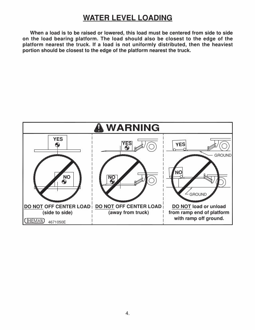
WATER LEVEL LOADING
When a load is to be raised or lowered, this load must be centered from side to sideon the load bearing platform. The load should also be closest to the edge of theplatform nearest the truck. If a load is not uniformly distributed, then the heaviestportion should be closest to the edge of the platform nearest the truck.
5.
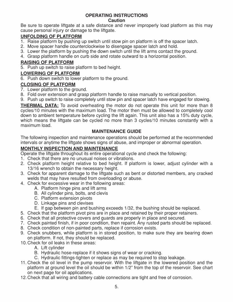
OPERATING INSTRUCTIONSCaution
Be sure to operate liftgate at a safe distance and never improperly load platform as this maycause personal injury or damage to the liftgate.UNFOLDING OF PLATFORM1. Raise platform by pushing up switch until stow pin on platform is off the spacer latch.2. Move spacer handle counterclockwise to disengage spacer latch and hold.3. Lower the platform by pushing the down switch until the lift arms contact the ground. 4. Grasp platform handle on curb side and rotate outward to a horizontal position.RAISING OF PLATFORM5. Push up switch to raise platform to bed height.LOWERING OF PLATFORM6. Push down switch to lower platform to the ground.CLOSING OF PLATFORM7. Lower platform to the ground.8. Fold over extension and grasp platform handle to raise manually to vertical position.9. Push up switch to raise completely until stow pin and spacer latch have engaged for stowing.THERMAL DATA: To avoid overheating the motor do not operate this unit for more than 8cycles/10 minutes with the maximum load. The motor then must be allowed to completely cooldown to ambient temperature before cycling the lift again. This unit also has a 15% duty cycle,which means the liftgate can be cycled no more than 3 cycles/10 minutes constantly with amaximum load.
MAINTENANCE GUIDEThe following inspection and maintenance operations should be performed at the recommendedintervals or anytime the liftgate shows signs of abuse, and improper or abnormal operation.MONTHLY INSPECTION AND MAINTENANCEOperate the liftgate throughout its entire operational cycle and check the following:1. Check that there are no unusual noises or vibrations.2. Check platform height relative to bed height. If platform is lower, adjust cylinder with a13/16 wrench to obtain the necessary height.
3. Check for apparent damage to the liftgate such as bent or distorted members, any crackedwelds that may have resulted from overloading or abuse.
4. Check for excessive wear in the following areas:A. Platform hinge pins and lift armsB. All cylinder pins, bolts, and clevisC. Platform extension pivotsD. Linkage pins and clevisesE. If gap between pin and bushing exceeds 1/32, the bushing should be replaced.
5. Check that the platform pivot pins are in place and retained by their proper retainers.6. Check that all protective covers and guards are properly in place and secured.7. Check painted finish, if in poor condition, then repaint. Any rusted parts should be replaced.8. Check condition of non-painted parts, replace if corrosion exists.9. Check snubbers, while platform is in stored position, to make sure they are bearing downon platform. If not, they should be replaced.
10.Check for oil leaks in these areas:A. Lift cylinderB. Hydraulic hose-replace if it shows signs of wear or cracking.C. Hydraulic fittings-tighten or replace as may be required to stop leakage.
11. Check the oil level in the pump reservoir. With the liftgate in the lowered position and theplatform at ground level the oil should be within 1/2” from the top of the reservoir. See charton next page for oil applications.
12.Check that all wiring and battery cable connections are tight and free of corrosion.
6.
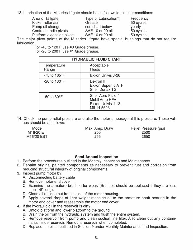
13. Lubrication of the M series liftgate should be as follows for all user conditions:
Area of Tailgate Type of Lubrication* FrequencyKicker roller asm Grease 50 cyclesPump oil change see chart below yearlyControl handle pivots SAE 10 or 20 oil 50 cyclesPlatform extension pivots SAE 10 or 20 oil 50 cycles
The major pivot points of the M series liftgate have special bushings that do not requirelubrication.
For -40 to 120 F use #0 Grade grease.For -20 to 200 F use #1 Grade grease.
HYDRAULIC FLUID CHART
Temperature Range
-75 to 165°F
-20 to 130°F
-50 to 80°F
Acceptable Fluids
Exxon Univis J-26
Dexron IIIExxon Superflo ATFShell Donax TG
Shell Aero Fluid 4Mobil Aero HFAExxon Univis J-13MIL H-5606
Semi-Annual Inspection1. Perform the procedures outlined in the Monthly Inspection and Maintenance.2. Repaint original painted components as necessary to prevent rust and corrosion fromreducing structural integrity of original components.
3. Inspect pump motor by:A. Disconnecting battery cableB. Remove motor end coverC. Examine the armature brushes for wear. (Brushes should be replaced if they are lessthan 1/8” long).
D. Clean all residue out from inside of the motor housing.E. Apply several drops of light weight machine oil to the armature shaft bearing in themotor end cover and reassemble the motor end cover.
4. If the hydraulic oil in the reservoir is dirty:A. Unfold platform and lower platform to the ground.B. Drain the oil from the hydraulic system and flush the entire system. C. Remove reservoir from pump and clean suction line filter. Also clean out any contami-nants inside reservoir. Remount reservoir when completed.
D. Replace the oil as outlined in Section 9 under Monthly Maintenance and Inspection.
14. Check the pump relief pressure and also the motor amperage at this pressure. These val-ues should be as follows:
Model Max. Amp. Draw Relief Pressure (psi)M16/20 ET 205 2500M16/20 EST 255 2650
7.
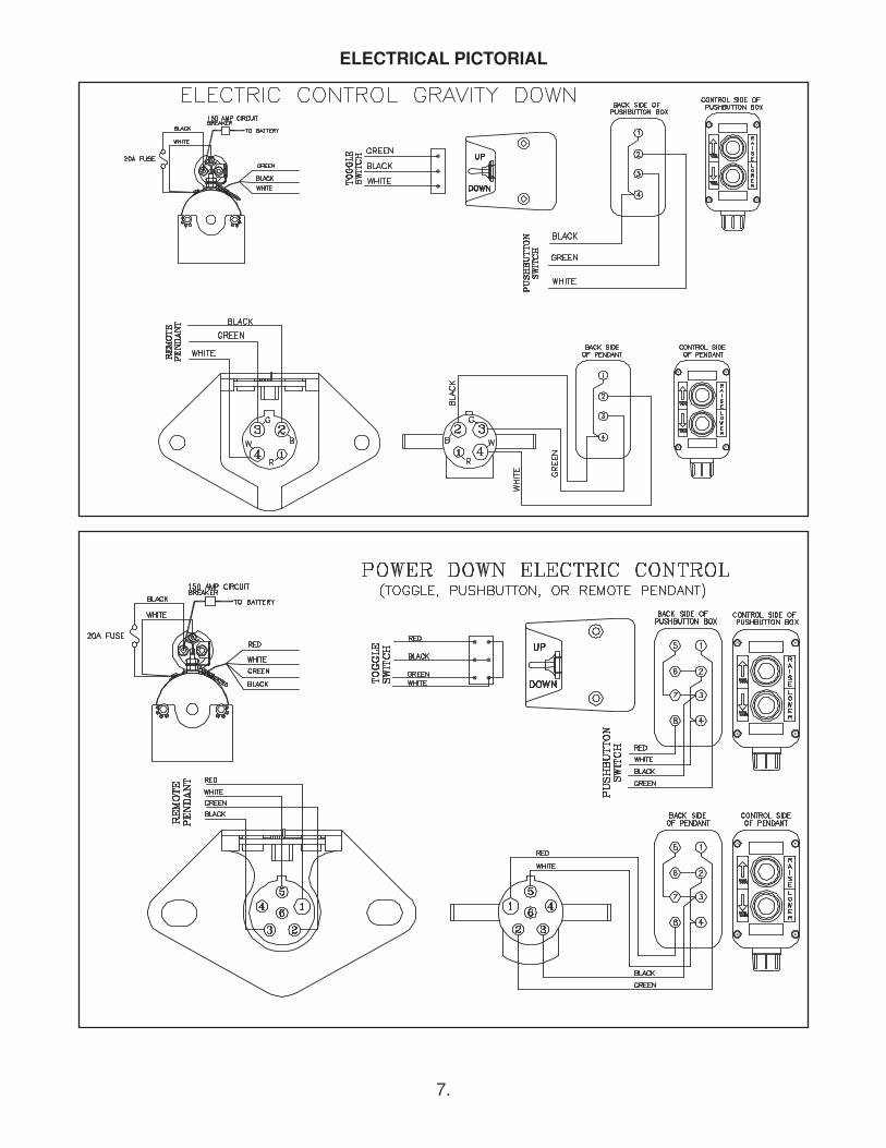
ELECTRICAL PICTORIAL

8.
INSPECTION AND LOCATION OF DECALS
Inspect all decals listed below to be certain they are in the proper location and they arelegible.
ALL DECALS MUST BE IN PLACE AND LEGIBLE OR ALL WARRANTIES ARE VOID!
Item Part Name Part Number1 Warning Decal-off center 46710502 Fast Idle Decal 46501502 PTO Decal 46501403 Danger Decal-no riding 46094 Operating Decal 46508905 Capacity Decal-1600# 46507505 Capacity Decal-2000# 46501006 Warning Decal-pinch point 46047 Handle decal 46058 Thieman Nameplate 46508009 Urgent Warning Decal 465053010 Reflector (3) 570511 Wiring Decal-Gravity Down 461211 Wiring Decal-Power Down 461412 Warning Decal 462013 Caution Decal 4650770
9.
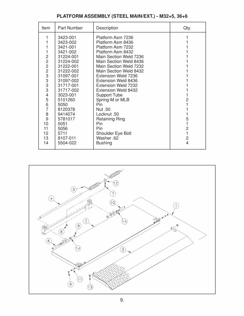
Item Part Number Description Qty.
1 3423-001 Platform Asm 7236 11 3423-002 Platform Asm 8436 11 3421-001 Platform Asm 7232 11 3421-002 Platform Asm 8432 12 31224-001 Main Section Weld 7236 12 31224-002 Main Section Weld 8436 12 31222-001 Main Section Weld 7232 12 31222-002 Main Section Weld 8432 13 31097-001 Extension Weld 7236 13 31097-002 Extension Weld 8436 13 31717-001 Extension Weld 7232 13 31717-002 Extension Weld 8432 14 3023-001 Support Tube 15 5101260 Spring-M or MLB 26 5050 Pin 17 8120378 Nut .50 18 9414074 Locknut .50 19 5781017 Retaining Ring 510 5051 Pin 111 5056 Pin 212 5711 Shoulder Eye Bolt 113 8107-011 Washer .62 214 5504-022 Bushing 4
PLATFORM ASSEMBLY (STEEL MAIN/EXT.) - M32+5, 36+6
10.
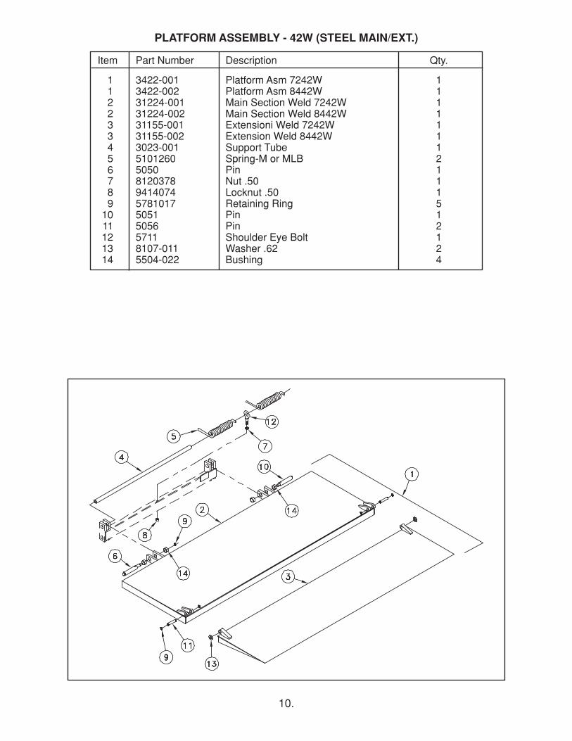
Item Part Number Description Qty.
1 3422-001 Platform Asm 7242W 11 3422-002 Platform Asm 8442W 12 31224-001 Main Section Weld 7242W 12 31224-002 Main Section Weld 8442W 13 31155-001 Extensioni Weld 7242W 13 31155-002 Extension Weld 8442W 14 3023-001 Support Tube 15 5101260 Spring-M or MLB 26 5050 Pin 17 8120378 Nut .50 18 9414074 Locknut .50 19 5781017 Retaining Ring 510 5051 Pin 111 5056 Pin 212 5711 Shoulder Eye Bolt 113 8107-011 Washer .62 214 5504-022 Bushing 4
PLATFORM ASSEMBLY - 42W (STEEL MAIN/EXT.)
11.
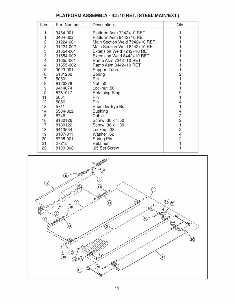
Item Part Number Description Qty.
1 3464-001 Platform Asm 7242+10 RET 11 3464-002 Platform Asm 8442+10 RET 12 31224-001 Main Section Weld 7242+10 RET 12 31224-002 Main Section Weld 8442+10 RET 13 31654-001 Extension Weld 7242+10 RET 13 31654-002 Extension Weld 8442+10 RET 14 31655-001 Ramp Asm 7242+10 RET 14 31655-002 Ramp Asm 8442+10 RET 15 3023-001 Support Tube 16 5101260 Spring 27 5050 Pin 18 8120378 Nut .50 19 9414074 Locknut .50 110 5781017 Retaining Ring 911 5051 Pin 112 5056 Pin 413 5711 Shoulder Eye Bolt 114 5504-022 Bushing 415 5746 Cable 216 8180126 Screw .38 x 1.50 217 8180122 Screw .38 x 1.00 118 9413534 Locknut .38 219 8107-011 Washer .62 420 5708-001 Spring Pin 221 27215 Retainer 122 8109-008 .25 Set Screw 1
PLATFORM ASSEMBLY - 42+10 RET. (STEEL MAIN/EXT.)
12.
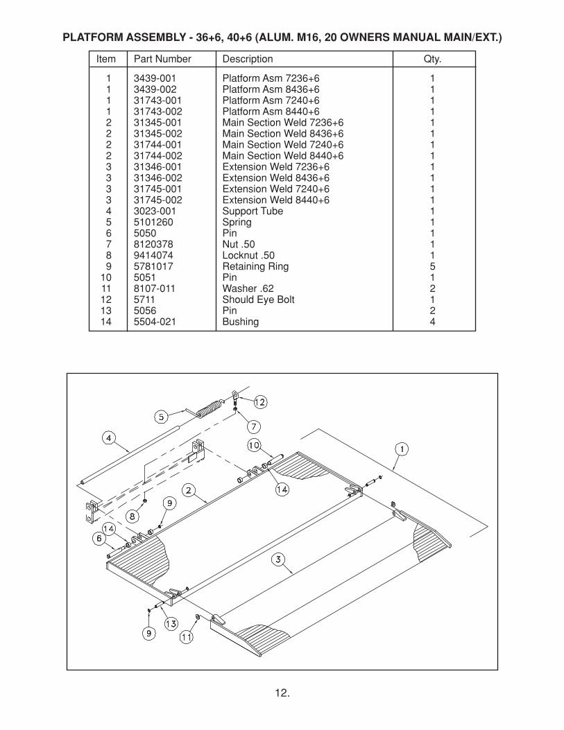
Item Part Number Description Qty.
1 3439-001 Platform Asm 7236+6 11 3439-002 Platform Asm 8436+6 11 31743-001 Platform Asm 7240+6 11 31743-002 Platform Asm 8440+6 12 31345-001 Main Section Weld 7236+6 12 31345-002 Main Section Weld 8436+6 12 31744-001 Main Section Weld 7240+6 12 31744-002 Main Section Weld 8440+6 13 31346-001 Extension Weld 7236+6 13 31346-002 Extension Weld 8436+6 13 31745-001 Extension Weld 7240+6 13 31745-002 Extension Weld 8440+6 14 3023-001 Support Tube 15 5101260 Spring 16 5050 Pin 17 8120378 Nut .50 18 9414074 Locknut .50 19 5781017 Retaining Ring 510 5051 Pin 111 8107-011 Washer .62 212 5711 Should Eye Bolt 113 5056 Pin 214 5504-021 Bushing 4
PLATFORM ASSEMBLY - 36+6, 40+6 (ALUM. M16, 20 OWNERS MANUAL MAIN/EXT.)
13.
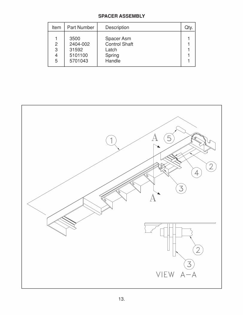
Item Part Number Description Qty.
1 3500 Spacer Asm 12 2404-002 Control Shaft 13 31592 Latch 14 5101100 Spring 15 5701043 Handle 1
SPACER ASSEMBLY
14.
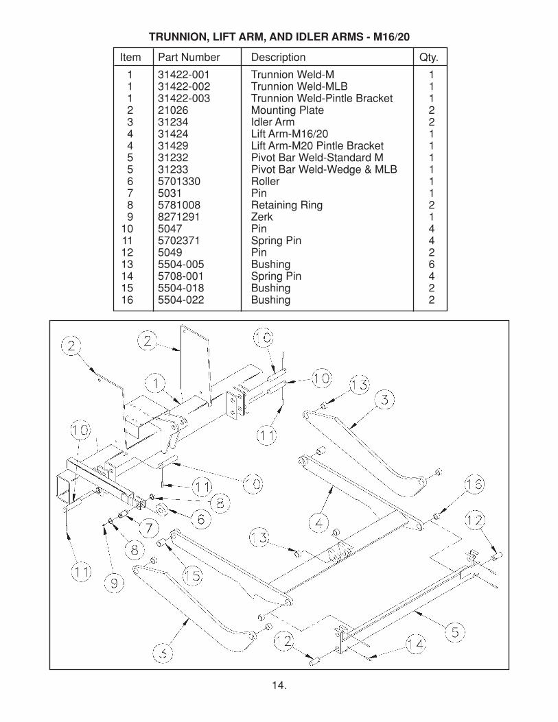
Item Part Number Description Qty.
1 31422-001 Trunnion Weld-M 11 31422-002 Trunnion Weld-MLB 11 31422-003 Trunnion Weld-Pintle Bracket 12 21026 Mounting Plate 23 31234 Idler Arm 24 31424 Lift Arm-M16/20 14 31429 Lift Arm-M20 Pintle Bracket 15 31232 Pivot Bar Weld-Standard M 15 31233 Pivot Bar Weld-Wedge & MLB 16 5701330 Roller 17 5031 Pin 18 5781008 Retaining Ring 29 8271291 Zerk 110 5047 Pin 411 5702371 Spring Pin 412 5049 Pin 213 5504-005 Bushing 614 5708-001 Spring Pin 415 5504-018 Bushing 216 5504-022 Bushing 2
TRUNNION, LIFT ARM, AND IDLER ARMS - M16/20
15.
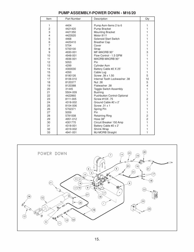
Item Part Number Description Qty
1 4404 Pump Asm-Items 2 to 6 12 4421420 Pump Bracket 13 4421350 Mounting Bracket 14 4423520 Motor 8111 15 4468 Solenoid Start Switch 16 4420410 Breather Cap 17 5704 Cover 18 5700100 Strap 19 4930-001 MF-MAORB 90° 310 4948-001 Flow Control - 1.5 GPM 111 4936-001 MAORB-MAORB 90° 112 5053 Pin 113 4299 Cylinder Asm 114 4300030 Battery Cable #2 X 25’ 115 4350 Cable Lug 116 8180126 Screw .38 x 1.50 517 8106-010 Internal Tooth Lockwasher .38 1018 8120377 Nut .38 519 8120388 Flatwasher .38 420 31445 Toggle Switch Assembly 121 5504-009 Bushing 122 4422860 Pushbutton Control-Optional 123 8111-005 Screw #10X .75 224 4318-002 Ground Cable #2 x 2' 125 8104-006 Screw .31 x 1 126 5702371 Spring Pin 127 5059 Pin 128 5781008 Retaining Ring 229 4951-012 Hose 38" 230 4301770 Circuit Breaker 150 Amp 131 4318-001 Battery Cable #2 x 2’ 132 4319-002 Shrink Wrap 133 4941-001 MJ-MORB Straight 1
PUMP ASSEMBLY-POWER DOWN - M16/20
16.
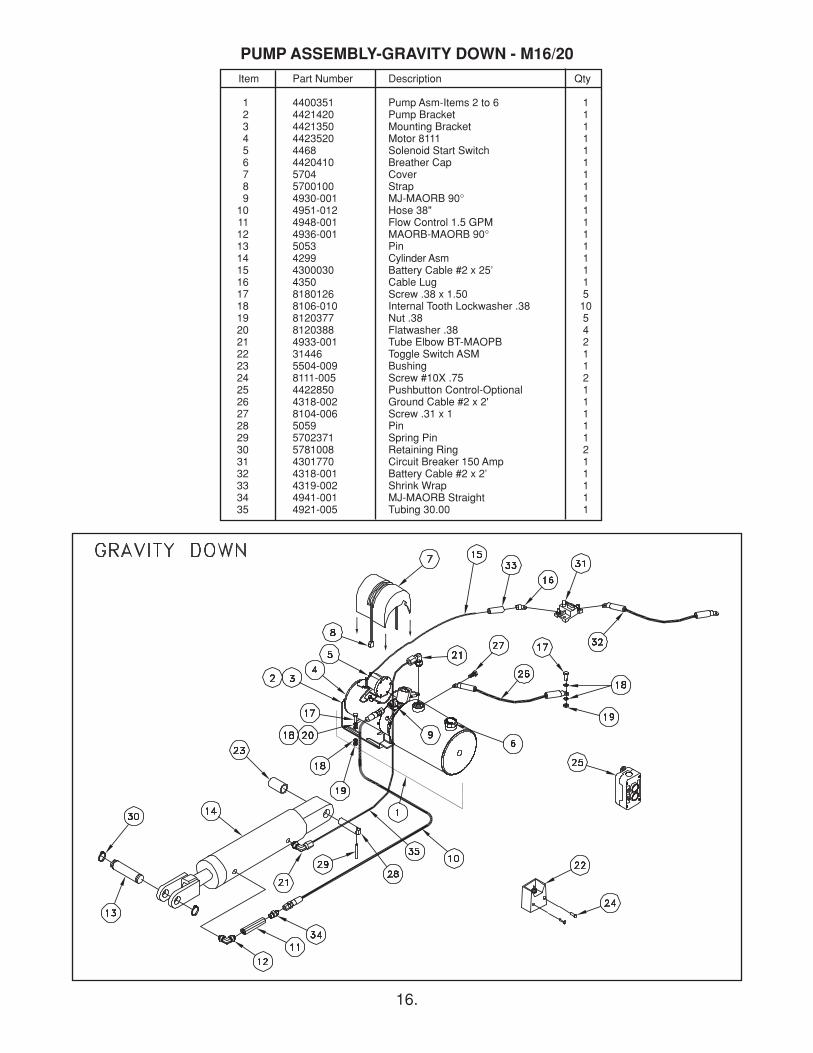
Item Part Number Description Qty
1 4400351 Pump Asm-Items 2 to 6 12 4421420 Pump Bracket 13 4421350 Mounting Bracket 14 4423520 Motor 8111 15 4468 Solenoid Start Switch 16 4420410 Breather Cap 17 5704 Cover 18 5700100 Strap 19 4930-001 MJ-MAORB 90° 110 4951-012 Hose 38" 111 4948-001 Flow Control 1.5 GPM 112 4936-001 MAORB-MAORB 90° 113 5053 Pin 114 4299 Cylinder Asm 115 4300030 Battery Cable #2 x 25’ 116 4350 Cable Lug 117 8180126 Screw .38 x 1.50 518 8106-010 Internal Tooth Lockwasher .38 1019 8120377 Nut .38 520 8120388 Flatwasher .38 421 4933-001 Tube Elbow BT-MAOPB 222 31446 Toggle Switch ASM 123 5504-009 Bushing 124 8111-005 Screw #10X .75 225 4422850 Pushbutton Control-Optional 126 4318-002 Ground Cable #2 x 2' 127 8104-006 Screw .31 x 1 128 5059 Pin 129 5702371 Spring Pin 130 5781008 Retaining Ring 231 4301770 Circuit Breaker 150 Amp 132 4318-001 Battery Cable #2 x 2’ 133 4319-002 Shrink Wrap 134 4941-001 MJ-MAORB Straight 135 4921-005 Tubing 30.00 1
PUMP ASSEMBLY-GRAVITY DOWN - M16/20
17.
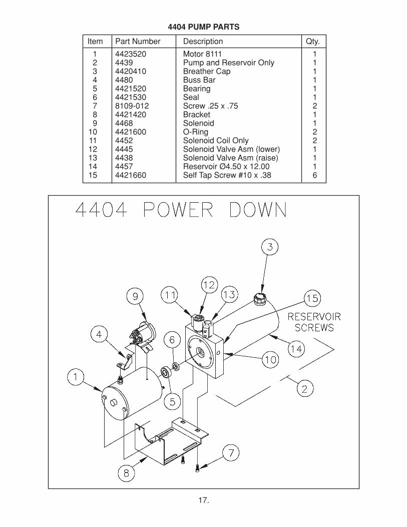
Item Part Number Description Qty.
1 4423520 Motor 8111 12 4439 Pump and Reservoir Only 13 4420410 Breather Cap 14 4480 Buss Bar 15 4421520 Bearing 16 4421530 Seal 17 8109-012 Screw .25 x .75 28 4421420 Bracket 19 4468 Solenoid 110 4421600 O-Ring 211 4452 Solenoid Coil Only 212 4445 Solenoid Valve Asm (lower) 113 4438 Solenoid Valve Asm (raise) 114 4457 Reservoir Ø4.50 x 12.00 115 4421660 Self Tap Screw #10 x .38 6
4404 PUMP PARTS
18.
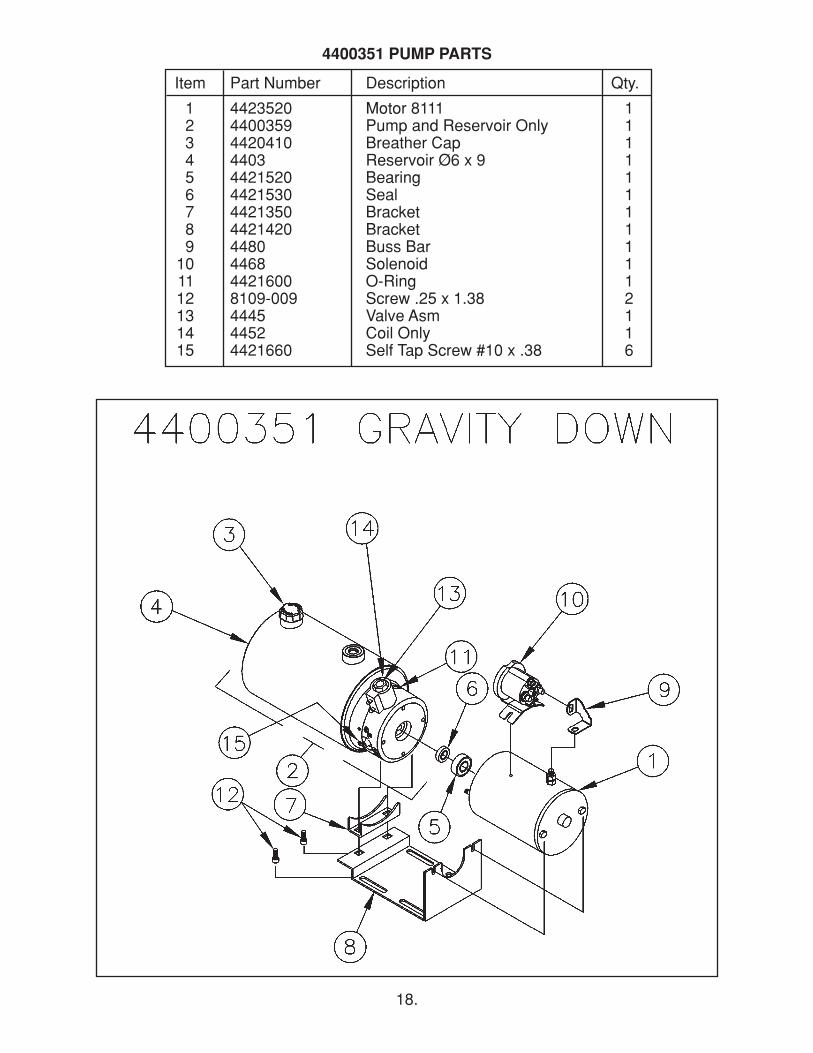
Item Part Number Description Qty.
1 4423520 Motor 8111 12 4400359 Pump and Reservoir Only 13 4420410 Breather Cap 14 4403 Reservoir Ø6 x 9 15 4421520 Bearing 16 4421530 Seal 17 4421350 Bracket 18 4421420 Bracket 19 4480 Buss Bar 110 4468 Solenoid 111 4421600 O-Ring 112 8109-009 Screw .25 x 1.38 213 4445 Valve Asm 114 4452 Coil Only 115 4421660 Self Tap Screw #10 x .38 6
4400351 PUMP PARTS
19.
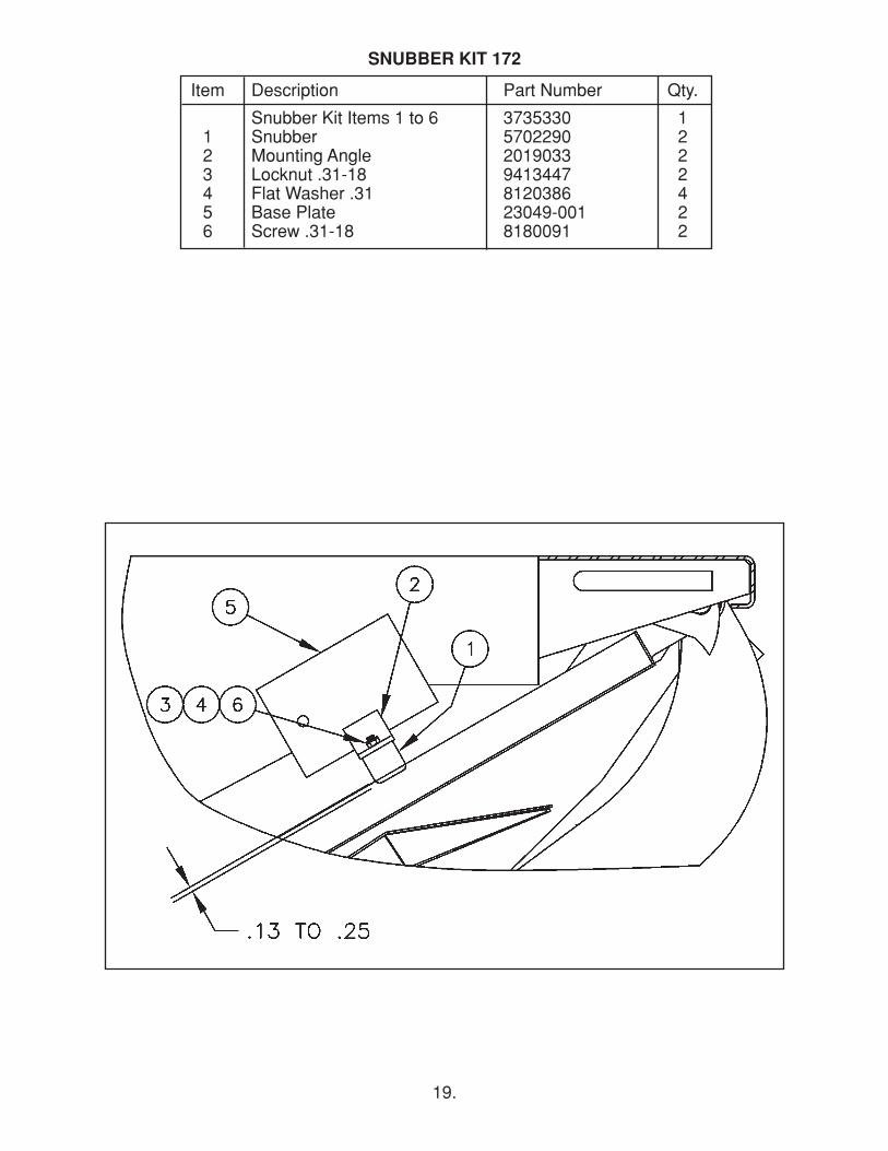
Item Description Part Number Qty.
Snubber Kit Items 1 to 6 3735330 11 Snubber 5702290 22 Mounting Angle 2019033 23 Locknut .31-18 9413447 24 Flat Washer .31 8120386 45 Base Plate 23049-001 26 Screw .31-18 8180091 2
SNUBBER KIT 172
20.
TROUBLESHOOTING GUIDEM16/20/25/30ET
Test Equipment: 1. 0-5000 psi pressure gauge2. DC voltmeter/ohm meter3. DC amp meter4. standard mechanics tools
Note: Please refer to the electrical diagrams and hose connection drawings in the liftgate’sowners manual when troubleshooting. This guide is only for standard Thieman liftgates.Special liftgates with options other than those in the owner’s manual will require specialdiagrams for troubleshooting. Read and understand this entire guide completely before doingany troubleshooting. Certain listed problems may be related to other problems listed so acomprehensive knowledge is required before proceeding.
Problem – Pump motor will not run in the raise mode
Causes – a. Tripped circuit breakerb. Blown 20A fusec. Defective or undercharged battery(ies)d. Improper battery cable connection or improper ground connectione. Defective or improperly wired raise switchf. Defective or improperly wired solenoid start switchg. Defective pump motor
Corrections – a. Reset the circuit breaker located within 2ft of the liftgate supplybattery(ies).
b. Replace 20A fuse.c. The “at rest” voltage for the batteries without the engine running andunder no load should be at least 12.5V. The minimum voltage betweenthe motor stud and ground is 9V at maximum load conditions. If propervoltage is not present, charge or replace the batteries. The battery(ies) onthe vehicle should be that which has a minimum 150 amp reservecapacity.
d. Trace battery and ground cable connections to locate improperconnection(s). Make sure the ground cable is installed going from thealuminum pump base to bare metal on the truck frame. Make sure theground cable from the batteries to the frame is a heavy 2ga. cable andthat it too is connected to bare metal on the frame. Make sure there is12.5V present at the large terminal on the motor start solenoid where the2ga. cable from the batteries is connected. Replace any damaged cablesand repair any bad connections.
e. Check for voltage on the black wire at the control switch. If no voltage ispresent the black wire from the motor start solenoid is loose or brokenand needs repaired. If voltage is present then check for voltage at thegreen and white wire on the switch with the switch in the “RAISE”position. If no voltage is present, replace the switch.
f. Check for voltage on the white wire at the motor start switch when theswitch is activated. If no voltage exists the white wire is loose or brokenbetween the switch and the motor start solenoid. Check that the purpleground wire on the start solenoid is connected properly and there are nobad connections. If there is voltage on the white wire and the coil doesnot energize or if there is no voltage present at the motor terminal thenreplace the start switch.
21.
g. With the switch activated in the “RAISE” position and the motor startsolenoid is activated, check for voltage at the motor terminal. If voltage ispresent and the motor is not running, replace the motor.
2. Problem – Liftgate will not raise to bed with a load and the pump motor running
Causes – a. Low hydraulic fluidb. Overload conditionc. Improperly adjusted or defective main relief valved. Lift cylinder is bypassing, liftgate is drifting downe. Broken hydraulic linef. Clogged or disconnected suction lineg. Defective pump
Corrections - a. Make sure the reservoir has the proper amount of fluid. Remove thebreather cap and check the fluid line through the fill hole. The hydraulicfluid should be within 1/2” of the top of the reservoir with the liftgate in thelowered position. Fill with Dexron III automatic transmission fluid.
b. The power unit on the M is equipped with a lifting relief valve to preventoverloading of the liftgate. The relief settings should be as follows: M16 2000 psiM20,M16 wedge 2525 psiM25,M20 wedge 2000 psiM30, M25 wedge 2525 psi
c. See section “c” above for relief valve setting. Plumb a pressure gaugeinto the high pressure circuit of the liftgate. Remove all loads from theliftgate’s platform. Engage the “RAISE” switch until the liftgate is fullyraised. Keep the “RAISE” switch engaged until the pump bypassesthrough the relief valve and note the pressure on the gauge at this time. Ifthe rated relief pressure is not present during relief, adjust the highpressure relief valve setting as necessary. If the relief pressure is notattainable the relief valve must be cleaned and/or replaced or the pump isdefective. See part “g” below.
d. If the liftgate will not raise with a load on the platform but empty is raisingslowly or only partially, the cylinder may be bypassing. To check for abypassing cylinder do the following. Lower the gate to the ground torelieve all pressure from the cylinder. Disconnect the cylinder from theliftarm. Press the “RAISE” switch until the cylinder is fully retracted.Disconnect the return line from the power unit and put the end of the linein a container to catch any oil which comes out during this test. Press the“RAISE” switch for 15 to 20 seconds and watch for a steady stream offluid coming out of the return line into the container. If no steady stream ofoil is present connect the hose to the butt end of the cylinder afterremoving the return line and fitting. Re-attach the return line and fitting tothe rod end port. Put the loose end of the return line in a container tocatch any oil, which comes out during this test. Press the “RAISE” switchuntil the cylinder is fully extended. Press the “RAISE” switch for 15 to 20seconds and watch for a steady stream of fluid coming out of one of thedisconnected hose ends into the container. Replace or rebuild anycylinder with fluid coming out of the return line, as this indicates fluid isbypassing the piston seals on the cylinder. Reconnect rebuilt or replacedcylinder and hoses as before.
22.
e. Broken or punctured hydraulic lines and fittings must be replaced withcare to avoid injury from high pressure oil streams.
f. With the liftgate at the ground, disconnect the power unit and remove thereservoir. Check to see if the suction tube is clogged or has fallen out ofthe pump base. Clean the screen or reattach the suction tube as required.
g. If all else fails replace the power unit, it is probably worn out.
3. Problem – Liftgate will not lowerCauses - a. Defective lowering solenoid coil or valve
b. Clogged or defective hydraulic lines, fittings or flow controls
Corrections - a. With the “LOWER” switch engaged check for voltage on the green wire atthe switch. If no voltage is present replace the switch. If voltage ispresent, with the “LOWER” switch engaged, check for voltage at thegreen wire on the lower solenoid valve coil terminal. If no voltage ispresent, the green wire from the “LOWER” switch is loose or broken andneeds replaced. If there is voltage (minimum of 9.5 volts) and the valve isnot opening to allow the gate to lower, either the lower coil is bad or theentire lower coil/valve assembly is bad. To check to see if the coil isdefective, remove the green wire from the spade terminal on the lowercoil and check for continuity between the spade terminal and the nut,which holds the coil on the valve stem. If continuity does not exist, replacethe defective coil, otherwise replace the defective lower coil/valveassembly.
b. Remove any obstruction in the hoses, fittings or flow controls or replaceany hose, fitting or flow control, which does not allow fluid to flow throughfreely.
4. Problem – Liftgate raises slowly – The raise speed of the M16/20/25/30 on a 54” bed heightwhile empty at 70°F is approximately 7-12 seconds. The raise speed loaded forthe same conditions is approximately 15-25 seconds. These speeds vary witheach model.
Causes - a. Overload conditionb. Cold weatherc. Partially blocked suction screend. Lift cylinder is bypassing e. Improperly adjusted or defective raise relief valvef. Low voltage and/or bad groundg. Worn out pump
Corrections – a. See section 2bb. Refer to Owner’s Manual for alternative oils to use for cold weatherconditions.
c. Remove reservoir and clean or replace suctionscreen as necessary.d. See section 2de. See section 2cf. The minimum voltage between the motor stud and ground is 9.5 volts atmaximum load conditions. See section 1b and 1c.
g. After all other corrections are performed it will be necessary to replace thepump.
23.
5. Problem – Foamy oil flowing from reservoir breatherCauses - a. Air is present in the system
b. Flow control is on backwardsc. Inoperable flow control
Corrections - a. Air can enter the system if the fluid level is low, see problem 2, part a, or ifthe suction tube is disconnected, see problem 2, part f. Also air may enterthrough fittings, which are not tightened properly, so check for any leaksaround fittings or hoses. Once the source of the air is determined, thecylinder must be bled of all air. Most air can be removed from the systemby lowering the gate to the ground to relieve all pressure from thecylinder, unpinning the cylinder and cycling them back and forth severaltimes from fully extended to fully retracted and allowing the pump tobypass through the relief valves for a few seconds in each direction.
b. The flow control provided is rated at 1.5GPM or 3.0GPM. The arrow onthe flow control must point away from the cylinder, designating thedirection of the controlled flow. Correct as needed.
c. Remove and disassemble the flow control and check for excessive wearand contamination. Clean as needed and reassemble. If this does notcorrect the problem replace the flow control.
If you have any questions or problems that are not covered in this guide please call Thieman’sEngineering Department at 1-800-524-5210.

Rev. 9/13 • 2.5C • MP79701