![Parte II - books.scielo.orgbooks.scielo.org/id/37f2w/pdf/gati-9788579837074-04.pdf · gunda] Escola de Viena substituíram o acorde perfeito assumem as formas Dó-Fá-Si, ... são](https://static.fdocuments.in/doc/165x107/5be81bd309d3f2d3638cc8e2/parte-ii-books-gunda-escola-de-viena-substituiram-o-acorde-perfeito-assumem.jpg)
53370-Owner's Manual/Parts List - Carga Fá · PDF filestowaway tailgates by thieman...
20
S TOW A WAY Tailgates By THIEMAN M16, 20, 25, 30 MLB16, 20, 25, 30 OWNERS MANUAL/PARTS LIST IMPORTANT! KEEP IN VEHICLE! ! PLEASE READ AND UNDERSTAND THE CONTENTS OF THIS MANUAL BEFORE OPERATING THE EQUIPMENT. TAILGATES, INC. 600 East Wayne Street Celina, Ohio 45822 Phone: 419-586-7727 Fax: 419-586-9724 HIEMAN NATIONAL TRUCK EQUIPMENT ASSOCIATION Member M-25 SHOWN
Transcript of 53370-Owner's Manual/Parts List - Carga Fá · PDF filestowaway tailgates by thieman...

STOWAAWWAAYYTailgates By THIEMAN
M16, 20, 25, 30 MLB16, 20, 25, 30OWNERS MANUAL/PARTS LIST
IMPORTANT! KEEP IN VEHICLE!!PLEASE READ AND UNDERSTAND THE CONTENTS OF THIS
MANUAL BEFORE OPERATING THE EQUIPMENT.
TAILGATES, INC.600 East Wayne Street
Celina, Ohio 45822Phone: 419-586-7727 Fax: 419-586-9724
HIEMANNATIONAL TRUCK EQUIPMENT ASSOCIATION
Member
M-25 SHOWN
TABLE OF CONTENTS
WARNINGS.........................................................................................2
PARTS ORDERING PROCEDURE ....................................................3
OPERATING INSTRUCTIONS............................................................5
MAINTENANCE GUIDE......................................................................5
SEMI-ANNUAL INSPECTION .............................................................6
ELECTRICAL PICTORIALS ................................................................7
INSPECTION AND LOCATION OF DECALS......................................8
PLATFORM ASM ........................................................................9 & 10
SPACER ASM....................................................................................11
TRUNNION, LIFT ARM, AND IDLER ARM ASM.......................12 & 13
PUMP ASM ELECTRIC CONTROL POWER DOWN...............14 & 15
PUMP ASM ELECTRIC CONTROL GRAVITY DOWN .............16 & 17
PTO PUMP ASM.......................................................................18 & 19
FOR YOUR RECORDSModel No. __________________________ Date Purchased _______________________
Serial No._________________________________________________________________NOTE: When Ordering Parts Be Sure To Include This Information!
WARNING!
The following list of warnings are to be read before operating the M series liftgate.
+ Read this Owners Manual and all of the decals on the liftgate BEFORE operating the lift-gate.
+ All protective covers and guards must be in place before operating the liftgate.
+ DO NOT operate the liftgate if you do not have a thorough knowledge and understanding ofthe operation of the liftgate.
+ NEVER OVERLOAD THE LIFTGATE. The maximum rated capacity of the M series liftgatediffers with each model as follows:
M16 – 1600LBS M25 – 2500LBSM20 – 2000LBS M30 – 3000LBS
+ Never use the liftgate if it makes any unusual noises, has vibrations, or fails to operatefreely.
2.
3.
+ Make certain that the area below the platform is clear before and at all times during theoperation of the liftgate.
+ Keep hands and feet clear of all pinch points.
+ The platform must be in the closed position and the transit latch engaged properly beforetransit.
+ Always load as close to the center of the platform and as close to the vehicle as possible.See figure 1.
+ Never operate lift trucks on or over any part of the platform.
+ Load and unload the platform from the rear and not from the side of the platform.
+ Only operate liftgate when vehicle is on level ground and the parking brake is set.
+ Follow the maintenance guide as outlined in this manual.
+ DO NOT attempt any repairs unless you are a qualified and authorized THIEMANdistributor.
+ If any repairs, adjustments, or maintenance not covered in this manual are required, con-tact your nearest Thieman distributor or the factory.
+ DO NOT ride the liftgate, it is not intended as a personal lift.
+ This liftgate is intended for the use of loading and unloading cargo only, it is not to be usedfor anything other than this.
+ DO NOT modify this liftgate. Altering this liftgate may cause serious personal injury or dam-age the liftgate and will void all warranties.
PARTS ORDERING PROCEDURE
When ordering parts, please include all the information asked for below. If this information isnot available, a complete written description or sketch of the required part will help Thiemanidentify and deliver the needed part to you.
THE FOLLOWING INFORMATION MUST BE INCLUDED:
1. Serial Number – Thieman liftgate serial numbers can be found on the tag located on thefront side of the trunnion tube.
2. Model Number and Capacity.3. Platform size and Material – Steel or Aluminum.4. Part number.5. Description.6. Quantity required.

4.
WATER LEVEL LOADING
When a maximum load is to be raised or lowered, this load must be centered on theload bearing platform, both front to back and side to side.
5.
OPERATING INSTRUCTIONSCaution
Be sure to operate liftgate at a safe distance and never improperly load platform as this maycause personal injury or damage to the liftgate.
UNFOLDING OF PLATFORM1. Raise platform by pushing up switch until stow pin on platform is off the spacer latch.2. Move spacer handle counterclockwise to disengage spacer latch and hold.3. Lower the platform by pushing the down switch until the lift arms contact the ground. 4. Grasp platform handle on curb side and rotate outward to a horizontal position.
RAISING OF PLATFORM5. Push up switch to raise platform to bed height.
LOWERING OF PLATFORM6. Push down switch to lower platform to the ground.
CLOSING OF PLATFORM7. Lower platform to the ground.8. Fold over extension and grasp platform handle to raise manually to vertical position.9. Push up switch to raise completely until stow pin and spacer latch have engaged for stow-
ing.
MAINTENANCE GUIDE
The following inspection and maintenance operations should be performed at the recommendedintervals or anytime the liftgate shows signs of abuse, and improper or abnormal operation.
MONTHLY INSPECTION AND MAINTENANCEOperate the liftgate throughout its entire operational cycle and check the following:1. Check that there are no unusual noises or vibrations.2. Check platform height relative to bed height. If platform is lower, adjust cylinder with a
13/16 wrench to obtain the necessary height.3. Check for apparent damage to the liftgate such as bent or distorted members, any cracked
welds which may have resulted from overloading or abuse.4. Check for excessive wear in the following areas:
A. Platform hinge pins and lift armsB. All cylinder pins, bolts, and clevisC. Platform extension pivotsD. Linkage pins and clevises
5. Check that the platform pivot pins are in place and retained by their proper retainers.6. Check that all protective covers and guards are properly in place and secured.7. Check for oil leaks in these areas:
A. Lift cylinderB. Hydraulic hose-replace if it shows signs of wear or cracking.C. Hydraulic fittings-tighten or replace as may be required to stop leakage.
8. Check the oil level in the pump reservoir. With the liftgate in the lowered position and theplatform at ground level the oil should be within 1/2” from the top of the reservoir. See chartbelow for oil applications.
9. Check that all wiring and battery cable connections are tight and free of corrosion.
6.
10. Lubrication of the M series liftgate should be as follows for all user conditions:
Area of Tailgate Type of Lubrication* FrequencyKicker roller asm Grease 50 cyclesPump oil change see chart below yearlyControl handle pivots SAE 10 or 20 oil 50 cyclesPlatform extension pivots SAE 10 or 20 oil 50 cycles
The major pivot points of the M series liftgate have special bushings that do not requirelubrication.
For -40 to 120 F use #0 Grade grease.For -20 to 200 F use #1 Grade grease.
HYDRAULIC FLUID CHART
Temperature Range
-75 to 165°F
-20 to 130°F
-50 to 80°F
Acceptable Fluids
Exxon Univis J-26
Dexron IIIExxon Superflo ATFShell Donax TG
Shell Aero Fluid 4Mobil Aero HFAExxon Univis J-13MIL H-5606
Semi-Annual Inspection1. Perform the procedures outlined in the Monthly Inspection and Maintenance.2. Inspect pump motor by:
A. Disconnecting battery cableB. Remove motor end coverC. Examine the armature brushes for wear. (Brushes should be replaced if they are less
than 1/8” long).D. Clean all residue out from inside of the motor housing.E. Apply several drops of light weight machine oil to the armature shaft bearing in the
motor end cover and reassemble the motor end cover.3. If the hydraulic oil in the reservoir is dirty:
A. Unfold platform and lower platform to the ground.B. Drain the oil from the hydraulic system and flush the entire system. C. Remove reservoir from pump and clean suction line filter. Also clean out any contami-
nants inside reservoir. Remount reservoir when completed.D. Replace the oil as outlined in Section 9 under Monthly Maintenance and Inspection.
11. Check the pump relief pressure and also the motor amperage at this pressure. These val-ues should be as follows:
Model Max. Amp. Draw Relief Pressure (psi)M16 175 2000
M20,M16 wedge 190 2525M25,M20 wedge 175 2000M25 wedge,M30 190 2525
7.
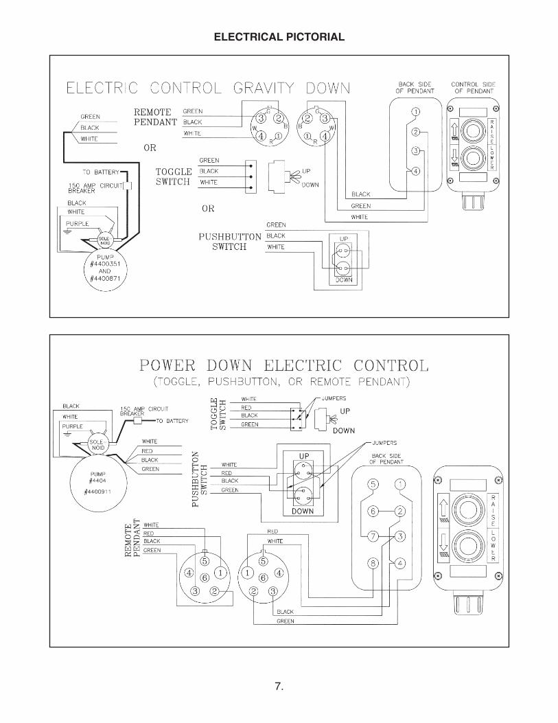
ELECTRICAL PICTORIAL
8.
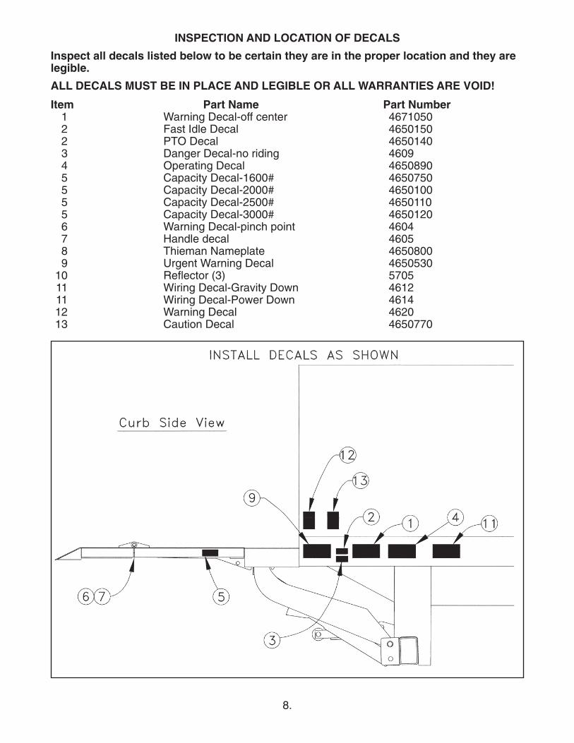
INSPECTION AND LOCATION OF DECALS
Inspect all decals listed below to be certain they are in the proper location and they arelegible.
ALL DECALS MUST BE IN PLACE AND LEGIBLE OR ALL WARRANTIES ARE VOID!
Item Part Name Part Number1 Warning Decal-off center 46710502 Fast Idle Decal 46501502 PTO Decal 46501403 Danger Decal-no riding 46094 Operating Decal 46508905 Capacity Decal-1600# 46507505 Capacity Decal-2000# 46501005 Capacity Decal-2500# 46501105 Capacity Decal-3000# 46501206 Warning Decal-pinch point 46047 Handle decal 46058 Thieman Nameplate 46508009 Urgent Warning Decal 4650530
10 Reflector (3) 570511 Wiring Decal-Gravity Down 461211 Wiring Decal-Power Down 461412 Warning Decal 462013 Caution Decal 4650770
9.
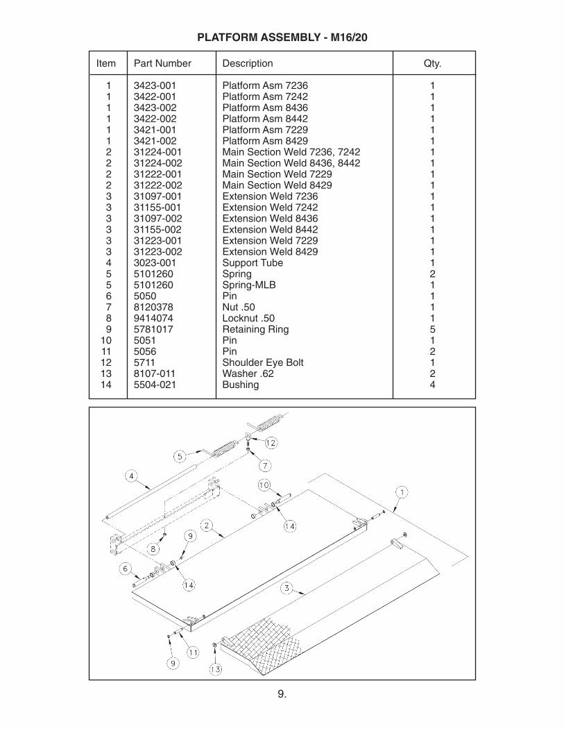
Item Part Number Description Qty.
1 3423-001 Platform Asm 7236 11 3422-001 Platform Asm 7242 11 3423-002 Platform Asm 8436 11 3422-002 Platform Asm 8442 11 3421-001 Platform Asm 7229 11 3421-002 Platform Asm 8429 12 31224-001 Main Section Weld 7236, 7242 12 31224-002 Main Section Weld 8436, 8442 12 31222-001 Main Section Weld 7229 12 31222-002 Main Section Weld 8429 13 31097-001 Extension Weld 7236 13 31155-001 Extension Weld 7242 13 31097-002 Extension Weld 8436 13 31155-002 Extension Weld 8442 13 31223-001 Extension Weld 7229 13 31223-002 Extension Weld 8429 14 3023-001 Support Tube 15 5101260 Spring 25 5101260 Spring-MLB 16 5050 Pin 17 8120378 Nut .50 18 9414074 Locknut .50 19 5781017 Retaining Ring 5
10 5051 Pin 111 5056 Pin 212 5711 Shoulder Eye Bolt 113 8107-011 Washer .62 214 5504-021 Bushing 4
PLATFORM ASSEMBLY - M16/20

10.
Item Part Number Description Qty.
1 31420-001 Platform Asm 7236 11 31426-001 Platform Asm 7242 11 31420-002 Platform Asm 8436 11 31426-002 Platform Asm 8442 11 31421-001 Platform Asm 7229 11 31421-002 Platform Asm 8429 12 31418-001 Main Section Weld 7236, 7242 12 31418-002 Main Section Weld 8436, 8442 12 31417-001 Main Section Weld 7229 12 31417-002 Main Section Weld 8429 13 31097-001 Extension Weld 7236 13 31155-001 Extension Weld 7242 13 31097-002 Extension Weld 8436 13 31155-002 Extension Weld 8442 13 31223-001 Extension Weld 7229 13 31223-002 Extension Weld 8429 14 3023-001 Support Tube 15 5101260 Spring 25 5101260 Spring-MLB 16 5050 Pin 17 8120378 Nut .50 18 9414074 Locknut .50 19 5781017 Retaining Ring 5
10 5051 Pin 111 5056 Pin 212 5711 Shoulder Eye Bolt 113 8107-011 Washer .62 214 5504-020 Bushing 215 5504-021 Bushing 2
PLATFORM ASSEMBLY - M25/30
11.
Item Part Number Description Qty.
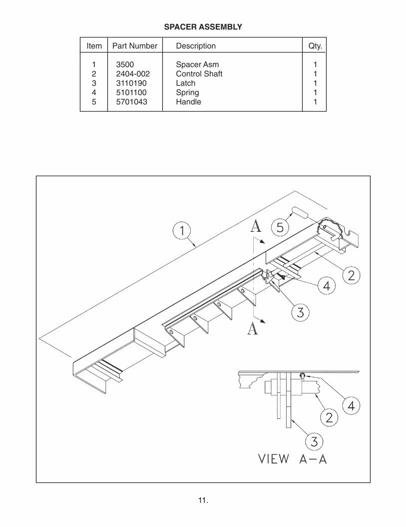
1 3500 Spacer Asm 12 2404-002 Control Shaft 13 3110190 Latch 14 5101100 Spring 15 5701043 Handle 1
SPACER ASSEMBLY
12.
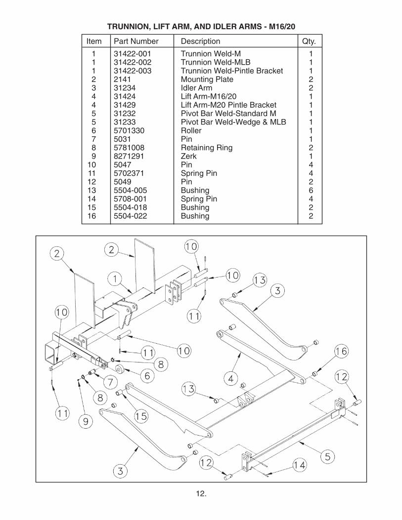
Item Part Number Description Qty.
1 31422-001 Trunnion Weld-M 11 31422-002 Trunnion Weld-MLB 11 31422-003 Trunnion Weld-Pintle Bracket 12 2141 Mounting Plate 23 31234 Idler Arm 24 31424 Lift Arm-M16/20 14 31429 Lift Arm-M20 Pintle Bracket 15 31232 Pivot Bar Weld-Standard M 15 31233 Pivot Bar Weld-Wedge & MLB 16 5701330 Roller 17 5031 Pin 18 5781008 Retaining Ring 29 8271291 Zerk 1
10 5047 Pin 411 5702371 Spring Pin 412 5049 Pin 213 5504-005 Bushing 614 5708-001 Spring Pin 415 5504-018 Bushing 216 5504-022 Bushing 2
TRUNNION, LIFT ARM, AND IDLER ARMS - M16/20
13.
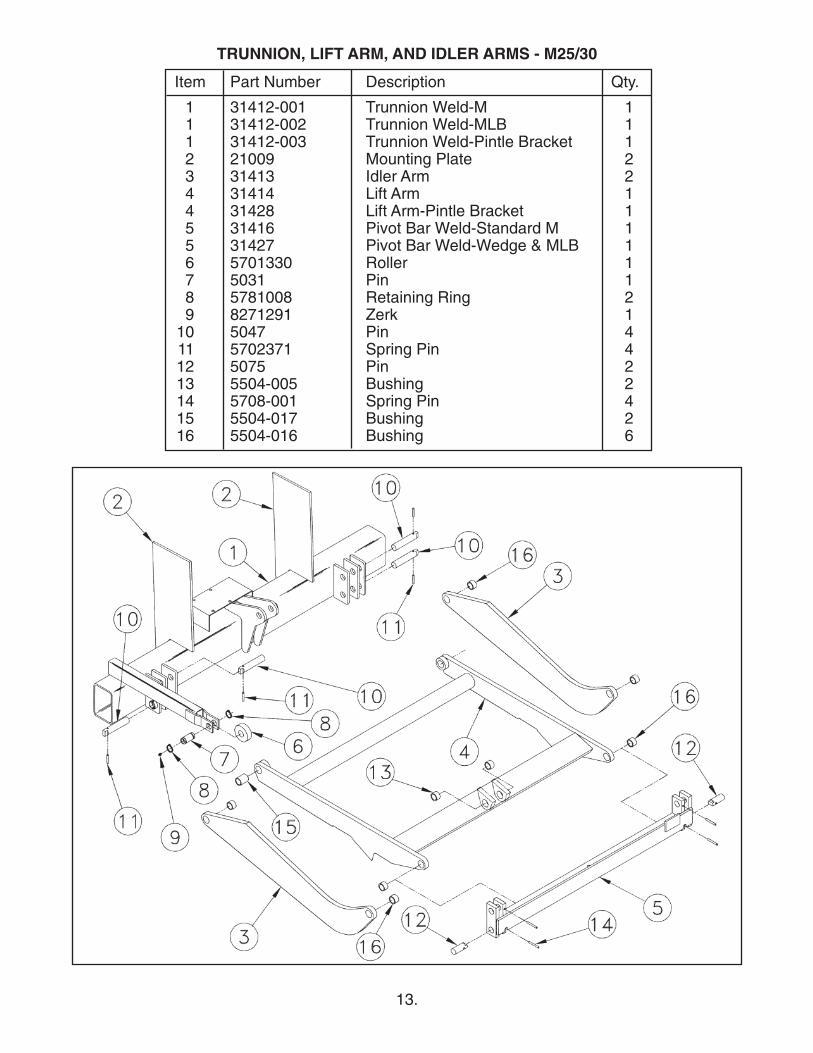
Item Part Number Description Qty.
1 31412-001 Trunnion Weld-M 11 31412-002 Trunnion Weld-MLB 11 31412-003 Trunnion Weld-Pintle Bracket 12 21009 Mounting Plate 23 31413 Idler Arm 24 31414 Lift Arm 14 31428 Lift Arm-Pintle Bracket 15 31416 Pivot Bar Weld-Standard M 15 31427 Pivot Bar Weld-Wedge & MLB 16 5701330 Roller 17 5031 Pin 18 5781008 Retaining Ring 29 8271291 Zerk 1
10 5047 Pin 411 5702371 Spring Pin 412 5075 Pin 213 5504-005 Bushing 214 5708-001 Spring Pin 415 5504-017 Bushing 216 5504-016 Bushing 6
TRUNNION, LIFT ARM, AND IDLER ARMS - M25/30
14.
Item Part Number Description Qty
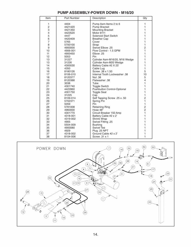
1 4404 Pump Asm-Items 2 to 6 12 4421420 Pump Bracket 13 4421350 Mounting Bracket 14 4423520 Motor 8111 15 4447 Solenoid Start Switch 16 4420409 Breather Cap 17 5765 Cover 18 5700100 Strap 19 4900000 Swivel Elbow .25 2
10 4906-001 Flow Control - 1.5 GPM 111 4900450 Elbow .25 112 5053 Pin 113 31227 Cylinder Asm-M16/20, M16 Wedge 113 31226 Cylinder Asm-M20 Wedge 114 4300030 Battery Cable #2 X 25’ 115 4350 Cable Lug 116 8180126 Screw .38 x 1.50 517 8106-010 Internal Tooth Lockwasher .38 1018 8120377 Nut .38 519 8120388 Flatwasher .38 420 3038 Tube 121 4301740 Toggle Switch 122 4422860 Pushbutton Control-Optional 123 4301750 Toggle Seal 124 31225 Cap 125 8109-014 Self Tapping Screw .25 x .50 226 5702371 Spring Pin 127 5059 Pin 128 5781008 Retaining Ring 229 4960000 Hose 48" 230 4301770 Circuit Breaker 150 Amp 131 4318-001 Battery Cable #2 x 2’ 132 4319-002 Shrink Wrap 133 4905 Swivel Fitting .25 134 5504-009 Bushing 135 4900080 Swivel Tee 136 4929 Plug .25 NPT 137 4318-002 Ground Cable #2 x 2' 138 8104-006 Screw .31 x 1 1
PUMP ASSEMBLY-POWER DOWN - M16/20
15.
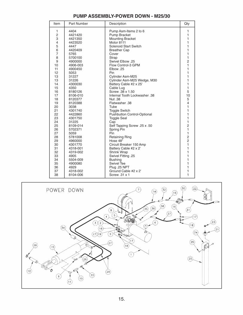
Item Part Number Description Qty
1 4404 Pump Asm-Items 2 to 6 12 4421420 Pump Bracket 13 4421350 Mounting Bracket 14 4423520 Motor 8111 15 4447 Solenoid Start Switch 16 4420409 Breather Cap 17 5765 Cover 18 5700100 Strap 19 4900000 Swivel Elbow .25 2
10 4906-003 Flow Control-3 GPM 111 4900450 Elbow .25 112 5053 Pin 113 31227 Cylinder Asm-M25 113 31226 Cylinder Asm-M25 Wedge, M30 114 4300030 Battery Cable #2 x 25' 115 4350 Cable Lug 116 8180126 Screw .38 x 1.50 517 8106-010 Internal Tooth Lockwasher .38 1018 8120377 Nut .38 519 8120388 Flatwasher .38 420 3038 Tube 121 4301740 Toggle Switch 122 4422860 Pushbutton Control-Optional 123 4301750 Toggle Seal 124 31225 Cap 125 8109-014 Self Tapping Screw .25 x .50 226 5702371 Spring Pin 127 5059 Pin 128 5781008 Retaining Ring 229 4960000 Hose 48" 230 4301770 Circuit Breaker 150 Amp 131 4318-001 Battery Cable #2 x 2' 132 4319-002 Shrink Wrap 133 4905 Swivel Fitting .25 134 5504-009 Bushing 135 4900080 Swivel Tee 136 4929 Plug .25 NPT 137 4318-002 Ground Cable #2 x 2' 138 8104-006 Screw .31 x 1 1
PUMP ASSEMBLY-POWER DOWN - M25/30
16.
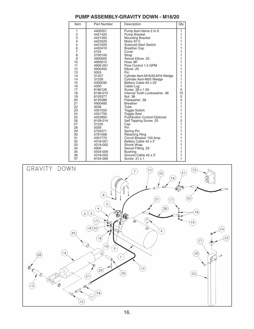
Item Part Number Description Qty
1 4400351 Pump Asm-Items 2 to 6 12 4421420 Pump Bracket 13 4421350 Mounting Bracket 14 4423520 Motor 8111 15 4421620 Solenoid Start Switch 16 4420410 Breather Cap 17 5704 Cover 18 5700100 Strap 19 4900000 Swivel Elbow .25 1
10 4965012 Hose 38" 111 4906-001 Flow Control 1.5 GPM 112 4900450 Elbow .25 113 5053 Pin 114 31227 Cylinder Asm-M16/20,M16 Wedge 114 31226 Cylinder Asm-M20 Wedge 115 4300030 Battery Cable #2 x 25’ 116 4350 Cable Lug 117 8180126 Screw .38 x 1.50 518 8106-010 Internal Tooth Lockwasher .38 1019 8120377 Nut .38 520 8120388 Flatwasher .38 421 4900480 Breather 122 3038 Tube 123 4301550 Toggle Switch 124 4301750 Toggle Seal 125 4422850 Pushbutton Control-Optional 126 8109-014 Self Tapping Screw .25 227 31225 Cap 128 5059 Pin 129 5702371 Spring Pin 130 5781008 Retaining Ring 131 4301770 Circuit Breaker 150 Amp 132 4318-001 Battery Cable #2 x 2’ 133 4319-002 Shrink Wrap 134 4905 Swivel Fitting .25 135 5504-009 Bushing 136 4318-002 Ground Cable #2 x 2' 137 8104-006 Screw .31 x 1 1
PUMP ASSEMBLY-GRAVITY DOWN - M16/20
17.
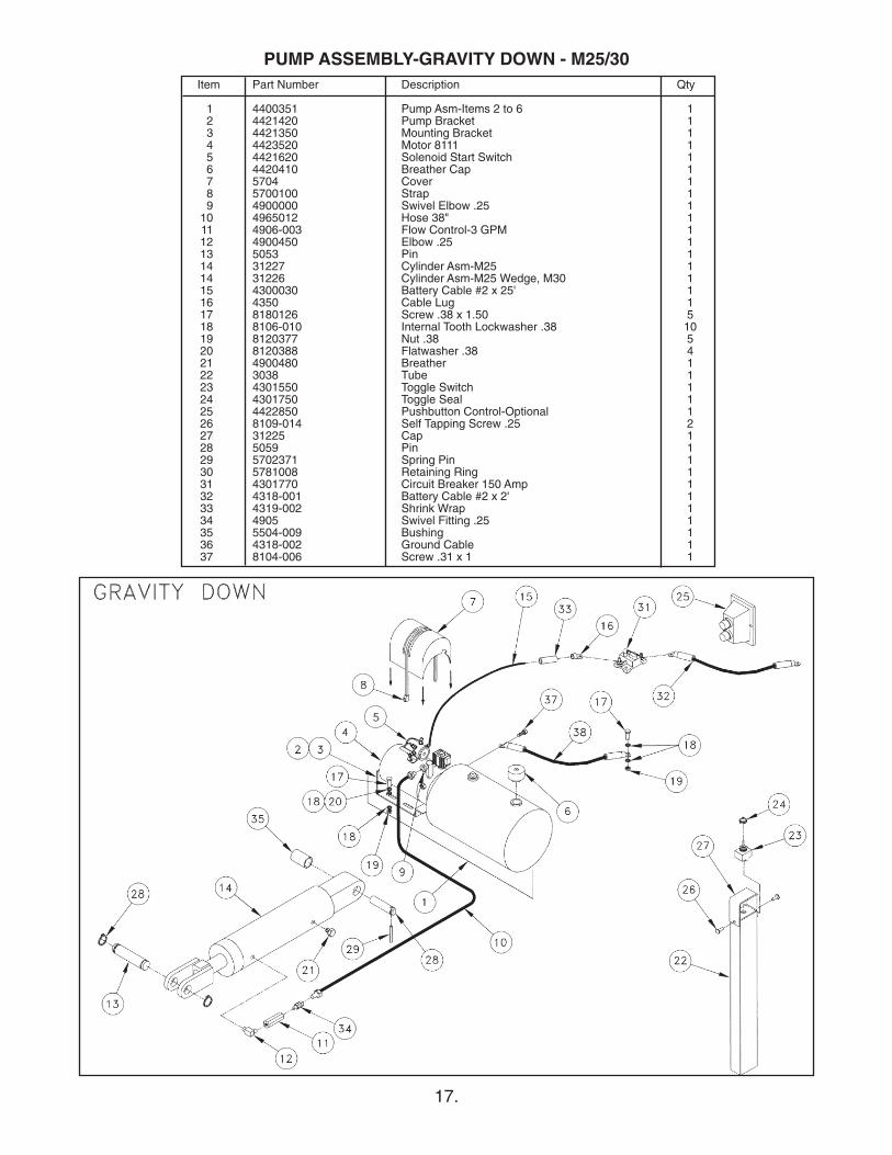
Item Part Number Description Qty
1 4400351 Pump Asm-Items 2 to 6 12 4421420 Pump Bracket 13 4421350 Mounting Bracket 14 4423520 Motor 8111 15 4421620 Solenoid Start Switch 16 4420410 Breather Cap 17 5704 Cover 18 5700100 Strap 19 4900000 Swivel Elbow .25 1
10 4965012 Hose 38" 111 4906-003 Flow Control-3 GPM 112 4900450 Elbow .25 113 5053 Pin 114 31227 Cylinder Asm-M25 114 31226 Cylinder Asm-M25 Wedge, M30 115 4300030 Battery Cable #2 x 25' 116 4350 Cable Lug 117 8180126 Screw .38 x 1.50 518 8106-010 Internal Tooth Lockwasher .38 1019 8120377 Nut .38 520 8120388 Flatwasher .38 421 4900480 Breather 122 3038 Tube 123 4301550 Toggle Switch 124 4301750 Toggle Seal 125 4422850 Pushbutton Control-Optional 126 8109-014 Self Tapping Screw .25 227 31225 Cap 128 5059 Pin 129 5702371 Spring Pin 130 5781008 Retaining Ring 131 4301770 Circuit Breaker 150 Amp 132 4318-001 Battery Cable #2 x 2' 133 4319-002 Shrink Wrap 134 4905 Swivel Fitting .25 135 5504-009 Bushing 136 4318-002 Ground Cable 137 8104-006 Screw .31 x 1 1
PUMP ASSEMBLY-GRAVITY DOWN - M25/30
18.
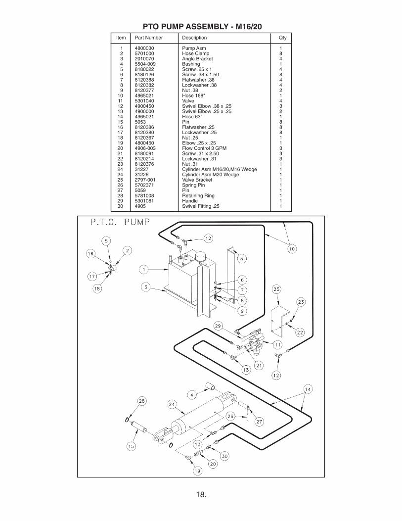
Item Part Number Description Qty
1 4800030 Pump Asm 12 5701000 Hose Clamp 83 2010070 Angle Bracket 44 5504-009 Bushing 15 8180022 Screw .25 x 1 46 8180126 Screw .38 x 1.50 87 8120388 Flatwasher .38 48 8120382 Lockwasher .38 49 8120377 Nut .38 2
10 4965021 Hose 168" 111 5301040 Valve 412 4900450 Swivel Elbow .38 x .25 313 4900000 Swivel Elbow .25 x .25 214 4965021 Hose 63" 115 5053 Pin 816 8120386 Flatwasher .25 817 8120380 Lockwasher .25 818 8120367 Nut .25 119 4800450 Elbow .25 x .25 120 4906-003 Flow Control 3 GPM 321 8180091 Screw .31 x 2.50 322 8120214 Lockwasher .31 323 8120376 Nut .31 1 24 31227 Cylinder Asm M16/20,M16 Wedge 124 31226 Cylinder Asm M20 Wedge 125 2797-001 Valve Bracket 126 5702371 Spring Pin 127 5059 Pin 128 5781008 Retaining Ring 129 5301081 Handle 130 4905 Swivel Fitting .25 1
PTO PUMP ASSEMBLY - M16/20
19.
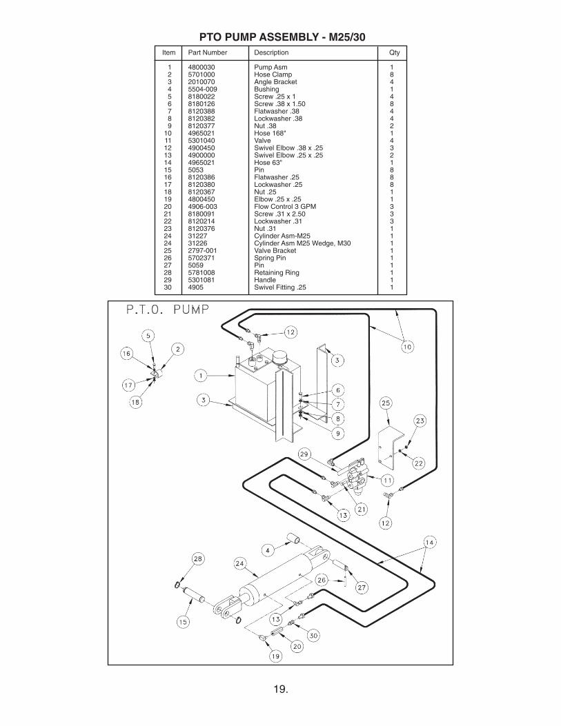
Item Part Number Description Qty
1 4800030 Pump Asm 12 5701000 Hose Clamp 83 2010070 Angle Bracket 44 5504-009 Bushing 15 8180022 Screw .25 x 1 46 8180126 Screw .38 x 1.50 87 8120388 Flatwasher .38 48 8120382 Lockwasher .38 49 8120377 Nut .38 2
10 4965021 Hose 168" 111 5301040 Valve 412 4900450 Swivel Elbow .38 x .25 313 4900000 Swivel Elbow .25 x .25 214 4965021 Hose 63" 115 5053 Pin 816 8120386 Flatwasher .25 817 8120380 Lockwasher .25 818 8120367 Nut .25 119 4800450 Elbow .25 x .25 120 4906-003 Flow Control 3 GPM 321 8180091 Screw .31 x 2.50 322 8120214 Lockwasher .31 323 8120376 Nut .31 1 24 31227 Cylinder Asm-M25 124 31226 Cylinder Asm M25 Wedge, M30 125 2797-001 Valve Bracket 126 5702371 Spring Pin 127 5059 Pin 128 5781008 Retaining Ring 129 5301081 Handle 130 4905 Swivel Fitting .25 1
PTO PUMP ASSEMBLY - M25/30

10/03 • 5C • MP53370


![McDonald's Portugal | McMenu, Happy Meal, Saladas e mais.ðeSabote8 (,Æiu) 2/2 (Simon Wadsworth, Rodrigo Carvalho, ]oão Ramos) Mim Fá Sol Quando acordas de manhã, come logo uma](https://static.fdocuments.in/doc/165x107/60bc7faf2c525a480c3d8f4f/mcdonalds-portugal-mcmenu-happy-meal-saladas-e-mais-esabote8-iu-22.jpg)


![Ú]Ê¥ õ¸ G&éO«Ø b JKè6ùX ªZ dõW% ¦ì|¿ fá Ð ß²¿ TEØ £ò% x ... · 9.7 Tabela de lubrificantes para rolamentos de ... Em caso de danos, ... [11] Rolamento de esferas](https://static.fdocuments.in/doc/165x107/5c2b2a6d09d3f29a638c1338/ue-o-geoo-b-jke6ux-az-dow-i-fa-d-ss-teo-o-x-.jpg)