Table of contents - passive component of Contents INDEX Subject ... SAP Part Number Explanation 1...
38
Transcript of Table of contents - passive component of Contents INDEX Subject ... SAP Part Number Explanation 1...


0
Table of Contents
INDEX
Subject Page
CERAMIC CAPACITOR PART NUMBER EXPLANATION……………………….…………………………………………… 1
CLASS Ⅰ 50V, 100V, 500V, 1KV, 2KV, 3KV, 6KV TEMPERATURE COMPENSATION TYPE……………………. 2~4
CLASS Ⅱ 50V, 100V, 500V, 1KV, 2KV, 3KV HI-K TYPE…………………………………………………………………. 5~9
CLASS Ⅲ SEMI-CONDUCTIVE TYPE……………………………………………………..…………………………………. 10
1KV, 2KV, 3KV LOW DISSPATION LB, LR TYPE……………………………………………………………………... 11~16
SAFETY STANDARD CERAMIC CAPACITOR PART NUMBER EXPLANATION……………………………………... 17
AH and AS Type-Class X1/Y1; AC Type-Class X1/Y2………………………………………………………………… 18~19
SAFETY STANDARD CERAMIC CAPACITOR DETAIL SPECIFICATION………………………...…………………. 20- 21
APPROVAL FILE NUMBER, TAPING SPECIFICATION AND DIMENSION, MARKING………………………...….. 22~26
RADIAL LEADED MULTILAYER CERAMIC CAPACITOR PART NUMBER EXPLANATION………………………….. 27
RADIAL LEADED CAPACITOR FEATURES DIMENSION………………………………………………………………….. 28
RADIAL LEADED CAPACITANCE RANGE AND MARKING……………..………………………….………………… 29~31
MPQ (Min Packing Quantity)……………………………………………………………………………………….…………. 32
*The specifications are subject to change or products in it may be discontinued without advance notice. Please check with our sales representatives or product
engineers before ordering.
*This catalog has only typical specifications because there is no space for detailed specifications. Therefore, please approve our product specifications or
transact the approval sheet for product specifications before ordering.
1
CERAMIC DISC CAPACITOR
SAP Part Number Explanation
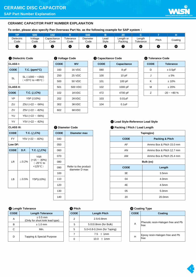
CERAMIC CAPACITOR PART NUMBER EXPLANATION
To order, please also specify Pan Overseas Part No. as the following example for SAP system:
YP 500 102 K 040 B 20 C 7 H
Dielectric Code
Voltage Code
Capacitance Code
Tolerance Code
Diameter Code
Lead Style
Length or Packing
Length Tolerance
Pitch Coating
❶ ❷ ❸ ❹ ❺ ❻ ❼ ❽ ❾ ❿
❶ Dielectric Code ❷ Voltage Code ❸ Capacitance Code ❹ Tolerance Code
CLASS I: CODE WV CODE Capacitance CODE Tolerance
CODE T.C. (ppm/°C) 160 16 VDC 080 8 pF D ± 0.5pF
SL SL (-1000 ~ +350)
(+20°C to +85°C)
250 25 VDC 100 10 pF J ± 5%
500 50 VDC 101 100 pF K ± 10%
CLASS II: 501 500 VDC 102 1000 pF M ± 20%
CODE T.C. (△C%) 102 1KVDC 472 4700 pF Z -20 ~ +80 %
YP Y5P (±10%) 202 2KVDC 103 0.01uF
ZU Z5U (+22 ~ -56%) 302 3KVDC 104 0.1uF
ZV Z5V (+22 ~ -82%) 602 6KVDC
YU Y5U (+22 ~ -56%)
YV Y5V (+22 ~ -82%) ❻ Lead Style-Reference Lead Style
CLASS III: ❺ Diameter Code ❼ Packing / Pitch / Lead Length
CODE T.C. (△C%) CODE Diameter max Taping(ex)
FY Y5V (+22 ~ -82%) 040
Refer to the product diameter D max
CODE Packing & Pitch
Low DF: 050 AF Ammo Box & Pitch 15.0 mm
CODE D.F. T.C. (△C%) 060 AN Ammo Box & Pitch 12.7 mm
LR ≦0.2%
Y5R (+15 ~ -30%)
(-25°C to
+125°C)
070 AM Ammo Box & Pitch 25.4 mm
080 Bulk (ex)
090 CODE Length
LB ≦0.5% Y5P(±10%)
100 3E 3.5mm
110 04 4.0mm
120 4E 4.5mm
130 05 5.0mm
140 20 20.0mm
❽ Length Tolerance ❾ Pitch ❿ Coating Type
CODE Length Tolerance CODE Length Pitch CODE Coating
A ± 0.5 mm
(Only for short kink lead type) 2 2.5±0.8mm
A Phenolic resin-Halogen free and Pb free B ± 1.0 mm 5 5.0±0.8mm (for Bulk)
C Min. 5 5.0+0.8-0.2mm (for Taping)
D Tapping & Special Purpose 7 7.5 ± 1mm
H Epoxy resin-Halogen free and Pb free 0 10.0 ± 1mm

2
CERAMIC DISC CAPACITOR
CLASS I 50V, 100V, 500V, 1KV, 2KV, 3KV, 6KV TEMPERATURE COMPENSATION TYPE
CERAMIC DISC CAPACITOR:
CLASS I 50V, 100V, 500V, 1KV, 2KV, 3KV, 6KV TEMPERATURE COMPENSATION TYPE
Features
Capacitance has linear temperature coefficient
Capacitance high stability
Epoxy Coating for 1KV, 2KV, 3KV, 6KV parts (equivalent to UL94V-0 standards)
RoHS Compliance
Halogen free products are available
Low lost at wide range of frequency
General specification
Capacitance Range 8pF to 820pF (See page 3 to page 5)
Capacitance Tolerance 0.5pF(for 8~10pF), 5%(for 10~820pF),
Operating Temperature Range -25℃ ~ +125℃.
Rated Voltage 50,100, 500, 1000, 2000, 3000 ,6000 VDC
Q Factor @ 1MHz, 1±0.2 Vrms, 25℃ C≧30 pF...........Q≧1,000, C<30 pF…......Q≧400+20*C
Insulation Resistance (IR) @ 25℃ 10,000 MΩ Minimum
Dielectric Strength
50~500VDC:3 times the rated WVDC ;
1K, 2K, 3KVDC:2 times the rated WVDC;
6KVDC:1.5 times the rated WVDC.
Testing Parameters 1MHz 20%, 1.0Vrms0.2Vrms
Lead style
Lead type Lead
Code Lead configuration Lead type
Lead
Code Lead configuration
Type 1
Straight long lead B
lead style:B
Type 4
Inside kink lead H
lead style:H
Type 2
Outside kink lead
X
lead style:X
Type 5
Vertical kink short
lead
D
lead style:D
Type 3
Straight short lead L
lead style:L
Type 6
Double outside kink
lead
M
lead style:M

3
CERAMIC DISC CAPACITOR
CLASS I 50V, 100V, 500V, 1KV, 2KV, 3KV, 6KV TEMPERATURE COMPENSATION TYPE
Manufacturing product range
Cap. Value v.s. Rate voltage, Product diameter & Type
Photo:
T.C SL
(CLASS Ⅰ, Temperature:+20℃~+85℃, T.C.C.: -1000 ~ +350ppm/℃)
Rate voltage 50V(SL500);100V(SL101) 500V(SL501) 1KV(SL102) 2KV(SL202)
Dφ(Code) 040 050 060 070 080 090 100 050 060 070 080 100 050 060 070 080 060 070 080
D max. (mm) 5.0 6.0 7.0 8.0 9.0 10.0 11.0 6.0 7.0 80 9.0 11.0 6.0 7.0 8.0 9.0 7.5 8.5 9.5
T max. (mm) 3.5 3.5 3.5 3.5 3.5 3.5 3.5 4.0 4.0 4.0 4.0 4.0 4.5 4.5 4.5 4.5 4.5 4.5 4.5
8 080 080
10 100 100 100
12 120 120 120
15 150 150 150 150
18 180 180 180 180
20 200 200 200 200
22 220 220 220 220
24 240 240 240 240
27 270 270 270 270
30 300 300 300 300
33 330 330 330 330
36 360 360 360 360
39 390 390 390 390
47 470 470 470 470
51 510 510 510 510
56 560 560 560 560
68 680 680 680 680
75 750 750 750 750
82 820 820 820 820
100 101 101 101 101
120 121 121 121 1 121
150 151 151 151 151
180 181 181 181
200 201 201 201
220 221 221 221
240 241 241
270 271 271
300 301 301
330 331 331
360 361 361
390 391 391
470 471
500 501
510 511
560 561
680 681
750 751
820 821
φd (mm) 0.55±0.05
Packing TAPING or BULK TAPING or BULK TAPING or BULK TAPING or BULK
Coating Phenolic Resin Phenolic or Epoxy Resin Epoxy Resin
Marking
1 2 3 4 5 6
Temperature
characteristic
Nominal
capacitance Rated voltage
Capacitance
tolerance
Manufacturer’s
identification
Halogen and Pb
free
SL:No marking.
Identified by
3-figure code.
Ex.
8pF"8"
100 pF"101"
50V/100V Marked as underline
D:±0.5pF
J:±5%
Shall be marked as
" " , but when
Dφ≦060 shall be
omitted.
There is a “_”
marking under
the code “V” as
the coating is
Halogen and Pb
free Epoxy
500V No marking (is blank)
1000V Marked “1kV”
2000V Marked “2kV”

4
CERAMIC DISC CAPACITOR
CLASS I 50V, 100V, 500V, 1KV, 2KV, 3KV, 6KV TEMPERATURE COMPENSATION TYPE
Manufacturing product range
Cap. Value v.s. Rate voltage, Product diameter & Type
Photo: SL302 SL602
T.C. SL
( Temperature:+20℃~+85℃, T.C.C.: -1000 ~ +350 ppm/℃)
Rate voltage 3KV(SL302) 6KV(SL602)
Dφ(Code) 060 070 080 060 070 080
D max. (mm) 7.5 8.5 9.5 7.5 8.5 9.5
T max. (mm) 5.0 5.0 5.0 5.0 5.0 5.0
10 100 100
12 120 120
15 150 150
18 180 180
20 200 200
22 220 220
24 240
27 270 270
30 300 300
33 330 330
36 360
39 390 390
47 470 470
51 510 510
56 560 560
62 620
68 680 680
75 750
82 820 820
100 101 101
φd (mm) 0.55±0.05
Packing TAPING or BULK
Coating Epoxy Resin
1 2 3 4 5 6
Temperature
characteristic
Nominal
capacitance
Capacitance
tolerance Rated voltage
Manufacturer's
identification Halogen and Pb free
SL:No marking
1. Cap.≥100pF
Ex. 120pF "121"
2. Cap<100pF,
Ex. 22pF"22"
D: ±0.5pF
J: ±5%
3000V :
Be marked “3kV”
6000V :
Be marked “6kV”
Shall be marked as
" " , but when Dφ≦
060 shall be omitted.
When the epoxy resin is
Halogn and Pb free, there
is a “-”marking.
Definition of date code marking:
7 8 9 10 11 12
Supplier of Epoxy No. of test equipment Factory of
manufacture Year of manufacture Month of manufacture
Week of manufacture by month
<: K-company
1~9: No.1~No.9,
J: No.10,
K: No.11,
L: No.12 ……
C: GZ Plant
D: DL Plant
5:2015,
6:2016,
7:2017,
……
1~9:January~
September,
O: October,
N: November,
D: December
week 1: –
week 2: •
week 3: :
week 4: ′
week 5: ;
5
CERAMIC DISC CAPACITOR
CLASS II 50V, 100V, 500V, 1KV, 2KV, 3KV Hi-K TYPE
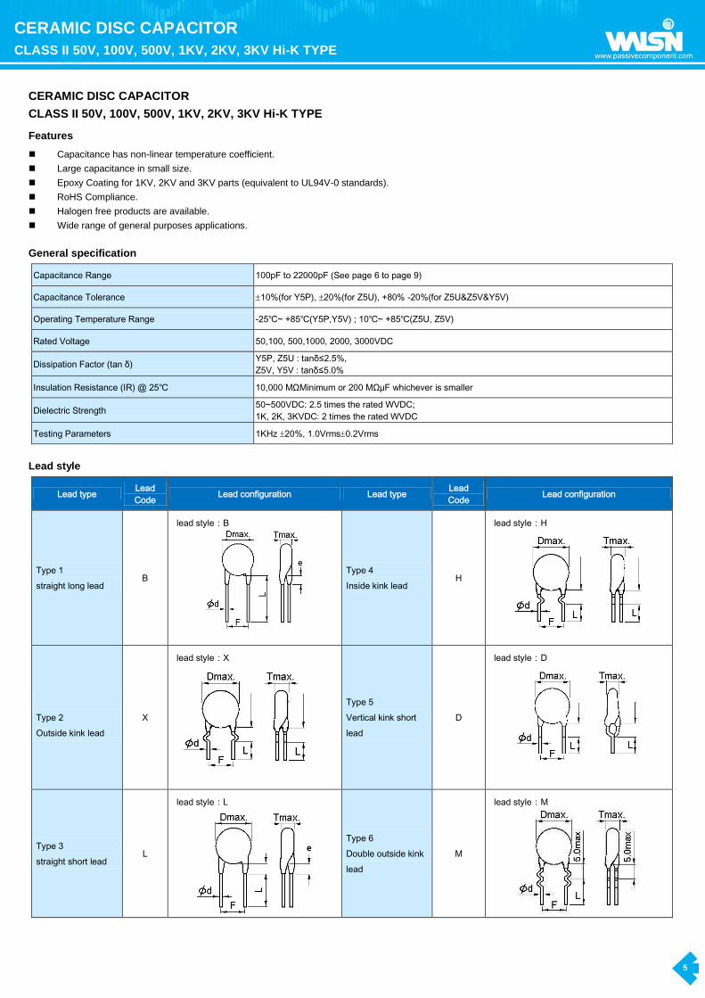
CERAMIC DISC CAPACITOR CLASS II 50V, 100V, 500V, 1KV, 2KV, 3KV Hi-K TYPE
Features
Capacitance has non-linear temperature coefficient.
Large capacitance in small size.
Epoxy Coating for 1KV, 2KV and 3KV parts (equivalent to UL94V-0 standards).
RoHS Compliance.
Halogen free products are available.
Wide range of general purposes applications.
General specification
Capacitance Range 100pF to 22000pF (See page 6 to page 9)
Capacitance Tolerance 10%(for Y5P), 20%(for Z5U), +80% -20%(for Z5U&Z5V&Y5V)
Operating Temperature Range -25℃~ +85℃(Y5P,Y5V) ; 10℃~ +85℃(Z5U, Z5V)
Rated Voltage 50,100, 500,1000, 2000, 3000VDC
Dissipation Factor (tan δ) Y5P, Z5U : tanδ≤2.5%,
Z5V, Y5V : tanδ≤5.0%
Insulation Resistance (IR) @ 25℃ 10,000 MΩMinimum or 200 MΩμF whichever is smaller
Dielectric Strength 50~500VDC: 2.5 times the rated WVDC;
1K, 2K, 3KVDC: 2 times the rated WVDC
Testing Parameters 1KHz 20%, 1.0Vrms0.2Vrms
Lead style
Lead type Lead
Code Lead configuration Lead type
Lead
Code Lead configuration
Type 1
straight long lead B
lead style:B
Type 4
Inside kink lead H
lead style:H
Type 2
Outside kink lead
X
lead style:X
Type 5
Vertical kink short
lead
D
lead style:D
Type 3
straight short lead L
lead style:L
Type 6
Double outside kink
lead
M
lead style:M

6
CERAMIC DISC CAPACITOR
CLASS II 50V, 100V, 500V, 1KV, 2KV, 3KV Hi-K TYPE
M a n u f a c t u r i n g p r o d u c t r a n g e
Cap. Value v.s. Rate voltage, product diameter & type
Photo:
T.C. Y5P
(CLASS Ⅱ, Temperature:-25℃~+85℃, T.C.C.:±10%)
Rate
voltage 50V(YP500) & 100V(YP101) 500V(YP501) 1KV(YP102) 2KV(YP202)
Dφ(Code) 040 050 060 070 080 090 100 040 050 060 070 080 090 100 110 130 050 060 070 080 100 120 060 080 090 100 130 140
D max. (mm) 4.5 5.5 6.5 7.5 8.5 9.5 11.0 4.5 5.5 6.5 7.5 9.0 10.0 11.0 12.0 14.0 6.0 7.0 8.0 9.0 11.0 13.0 7.5 9.5 10.5 11.5 14.5 15.5
T max. (mm) 3.5 3.5 3.5 3.5 3.5 3.5 3.5 4.0 4.0 4.0 4.0 4.0 4.0 4.0 4.0 4.0 4.5 4.5 4.5 4.5 4.5 4.5 4.5 4.5 4.5 4.5 4.5 4.5
100 101 101 101 101
120 121 121 121 121
150 151 151 151 151
180 181 181 181 181
200 201 201 201 201
220 221 221 221 221
240 241 241 241 241
270 271 271 271 271
330 331 331 331 331
390 391 391 391 391
470 471 471 471 471
560 561 561 561 561
680 681 681 681 681
820 821 821 821 821
1000 102 102 102 102
1200 122 122 122 122
1500 152 152 152 152
1800 182 182 182 182
2000 202 202 202 202
2200 222 222 222 222
2700 272 272 272 272
3000 302 302 302
3300 332 332 332 332
3900 392 392 392 392
4700 472 472 472 472
5000 502 502
5600 562 562
6800 682 682
8200 822 822
10000 103 103
φd (mm) 0.55±0.05
Packing TAPING or BULK BULK TAPING or BULK BULK TAPING or BULK BULK TAPING or BULK BULK
Coating Phenolic Resin Phenolic or Epoxy Resin Epoxy Resin
Marking
1 2 3 4 5 6
Temperature
characteristic
Nominal
capacitance Rated voltage
Capacitance
tolerance
Manufacturer’s
identification
Halogen and
Pb free
Be marked “B”.
Identified by
3-figure code.
Ex.
1000pF"102"
3300pF"332"
50V/100V Marked as underline
K:±10%
Shall be marked as
" " , but when Dφ
≦060 shall be
omitted.
There is a “_”
marking under
the code “V” as
the coating is
Halogen and Pb
free Epoxy.
500V No marking (is blank)
1000V Marked “1kV”
2000V Marked “2kV”
7
CERAMIC DISC CAPACITOR
CLASS II 50V, 100V, 500V, 1KV, 2KV, 3KV Hi-K TYPE
M a n u f a c t u r i n g p r o d u c t r a n g e
Cap. Value v.s. Rate voltage, product diameter & type
Photo:
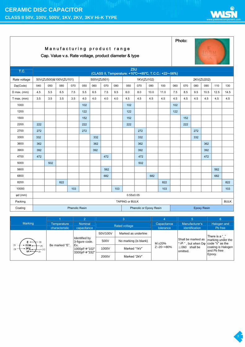
T.C. Z5U
(CLASS Ⅱ, Temperature: +10℃~+85℃, T.C.C.: +22~-56%)
Rate voltage 50V(ZU500)&100V(ZU101) 500V(ZU501) 1KV(ZU102) 2KV(ZU202)
Dφ(Code) 040 050 060 070 050 060 070 090 050 070 090 100 060 070 080 090 110 130
D max. (mm) 4.5 5.5 6.5 7.5 5.5 6.5 7.5 9.5 6.0 8.0 10.0 11.0 7.5 8.5 9.5 10.5 12.5 14.5
T max. (mm) 3.5 3.5 3.5 3.5 4.0 4.0 4.0 4.0 4.5 4.5 4.5 4.5 4.5 4.5 4.5 4.5 4.5 4.5
1000 102 102 102
1200 122 122 122
1500 152 152 152
2200 222 222 222 222
2700 272 272 272 272
3300 332 332 332 332
3600 362 362 362 362
3900 392 392 392 392
4700 472 472 472 472
5000 502 502
5600 562 562
6800 682 682 682
8200 822 822 822
10000 103 103 103 103
φd (mm) 0.55±0.05
Packing TAPING or BULK BULK
Coating Phenolic Resin Phenolic or Epoxy Resin Epoxy Resin
Marking
1 2 3 4 5 6
Temperature
characteristic
Nominal
capacitance Rated voltage
Capacitance
tolerance
Manufacturer’s
identification
Halogen and
Pb free
Be marked “E”.
Identified by 3-figure code. Ex. 1000pF"102" 3300pF"332"
50V/100V Marked as underline
M:±20% Z:-20~+80%
Shall be marked as
" " , but when Dφ≦060 shall be
omitted.
There is a “_” marking under the code “V” as the coating is Halogen and Pb free Epoxy.
500V No marking (is blank)
1000V Marked “1kV”
2000V Marked “2kV”

8
CERAMIC DISC CAPACITOR
CLASS II 50V, 100V, 500V, 1KV, 2KV, 3KV Hi-K TYPE
M a n u f a c t u r i n g p r o d u c t r a n g e
Cap. Value v.s. Rate voltage, product diameter & type
Photo:
T.C. Z5V
(CLASS Ⅱ, Temperature: +10℃~+85℃, T.C.C.: +22~-82%)
Rate voltage 50V(ZV500) & 100V(ZV101) 500V(ZV501) 1KV(ZV102) 2KV(ZV202)
Dφ (Code) 050 060 070 080 080 060 080 100 120
D max. (mm) 5.5 6.5 7.5 8.5 9.0 7.0 9.0 11.0 13.5
T max. (mm) 3.5 3.5 3.5 3.5 4.0 4.5 4.5 4.5 4.5
1000 102
1500 152 152
2200 222 222
2700 272 272
3300 332 332
3900 392 392
4700 472 472
10000 103 103 103 103
20000 203
22000 223
φd (mm) 0.55±0.05
Packing TAPING or BULK BULK
Coating Phenolic Resin Phenolic or Epoxy Resin Epoxy Resin
T.C. Y5V (CLASS Ⅱ, Temperature: -25℃~+85℃, T.C.C.: +22% ~-82%)
Rate voltage 50V(YV500) 100V(YV101) 500V(YV501) 1KV(YV102) 2KV(YV202)
Dφ(Code) 040 050 060 080 040 050 060 050 070 080 100 070 120
D max. (mm) 4.5 5.5 6.6 8.5 4.5 5.5 6.6 5.5 7.5 8.5 11.0 8.5 13.5
T max. (mm) 3.5 3.5 3.5 3.5 3.5 3.5 3.5 4.0 4.0 4.0 4.5 5.0 5.0
1000 102 102 102
2200 222 222 222 222
4700 472 472 472
10000 103 103 103 103 103
22000 223
φd (mm) 0.55±0.05
Packing TAPING or BULK BULK
Coating Phenolic Resin Phenolic or
Epoxy Resin Epoxy Resin
Marking
1 2 3 4 5 6
Temperature
characteristic
Nominal
capacitance Rated voltage
Capacitance
tolerance
Manufacturer’s
identification
Halogen and
Pb free
Z5V,Y5V: the logo
is “F”, but the “F”
shall be omitted.
Identified by
3-figure code.
Ex.
1000pF"102"
3300pF"332"
4700pF"472"
50V/100V Marked as underline
M:±20%
Z:-20~+80%
Shall be marked as
" " , but when
Dφ≦060 shall be
omitte
There is a “_”
marking under
the code “V” as
the coating is
Halogen and Pb
free Epoxy.
500V No marking (is blank)
1000V Marked “1kV”
2000V Marked “2kV”
2000V Marked “2kV”
9
CERAMIC DISC CAPACITOR
CLASS II 50V, 100V, 500V, 1KV, 2KV, 3KV Hi-K TYPE
M a n u f a c t u r i n g p r o d u c t r a n g e
Cap. Value v.s. Rate voltage, product diameter & type
Photo: Y5P Z5U
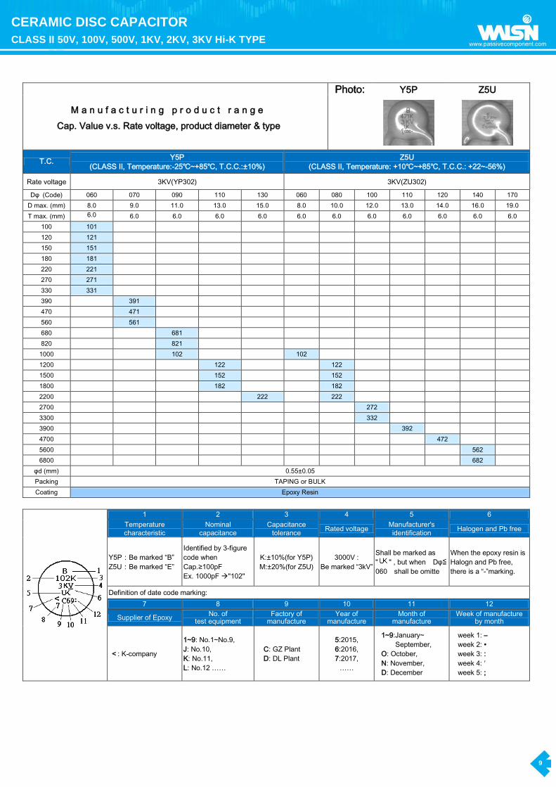
T.C. Y5P
(CLASS Ⅱ, Temperature:-25℃~+85℃, T.C.C.:±10%)
Z5U
(CLASS Ⅱ, Temperature: +10℃~+85℃, T.C.C.: +22~-56%)
Rate voltage 3KV(YP302) 3KV(ZU302)
Dφ (Code) 060 070 090 110 130 060 080 100 110 120 140 170
D max. (mm) 8.0 9.0 11.0 13.0 15.0 8.0 10.0 12.0 13.0 14.0 16.0 19.0
T max. (mm) 6.0 6.0 6.0 6.0 6.0 6.0 6.0 6.0 6.0 6.0 6.0 6.0
100 101
120 121
150 151
180 181
220 221
270 271
330 331
390 391
470 471
560 561
680 681
820 821
1000 102 102
1200 122 122
1500 152 152
1800 182 182
2200 222 222
2700 272
3300 332
3900 392
4700 472
5600 562
6800 682
φd (mm) 0.55±0.05
Packing TAPING or BULK
Coating Epoxy Resin
1 2 3 4 5 6
Temperature
characteristic
Nominal
capacitance
Capacitance
tolerance Rated voltage
Manufacturer's
identification Halogen and Pb free
Y5P:Be marked “B”
Z5U:Be marked “E”
Identified by 3-figure
code when
Cap.≥100pF
Ex. 1000pF "102"
K:±10%(for Y5P)
M:±20%(for Z5U)
3000V :
Be marked “3kV”
Shall be marked as
" " , but when Dφ≦
060 shall be omitte
When the epoxy resin is
Halogn and Pb free,
there is a “-”marking.
Definition of date code marking:
7 8 9 10 11 12
Supplier of Epoxy No. of
test equipment Factory of
manufacture Year of
manufacture Month of
manufacture Week of manufacture
by month
<: K-company
1~9: No.1~No.9,
J: No.10,
K: No.11,
L: No.12 ……
C: GZ Plant
D: DL Plant
5:2015,
6:2016,
7:2017,
……
1~9:January~
September,
O: October,
N: November,
D: December
week 1: –
week 2: •
week 3: :
week 4: ′
week 5: ;

10
CERAMIC DISC CAPACITOR
CLASS III SEMI-CONDUCTIVE TYPE
CERAMIC DISC CAPACITOR CLASS III SEMI-CONDUCTIVE TYPE
Features
Large capacitance in small size
Low lost at wide range of frequency
Cost saving by placing film capacitors
Capacitance has linear temperature coefficient
Stable capacitance change over specified temperature range
RoHS Compliance
Halogen free products are available
General specification
Capacitance Range 100000pF
Capacitance Tolerance +80%-20%
Operating Temperature Range -25℃ ~+ 85℃
Rated Voltage 16, 25 & 50 VDC
Dissipation Factor (tan δ) Y5V 16V…..tan δ≦7.5%;
Y5V 25/50V……tan δ≦5.0%
Insulation Resistance (IR) @ 25℃ 16V…….100MΩ Minimum or 10MΩμF
25/50V…1000MΩ Minimum or 20MΩμF
Dielectric Strength 2 times the rated WVDC
Testing Parameters 1KHz20%, 0.1Vrms Maximum
Capacitance chart
Manufacturing Product Range T.C. FY (Y5V) CLASS III
Rate voltage 16V 25V 50V
Dφ(Code) 060 060 060
D max. (mm) 7.0 7.0 7.0
T max. (mm) 3.5 3.5 3.5
0.1uF 104 104 104
φd (mm) 0.55±0.05
Packing TAPING or BULK
Coating Phenolic Resin
Marking
1 2 3 4 5
Temperature
characteristic
Nominal
capacitance Rated voltage
Capacitance
tolerance
Manufacturer’s
identification
Y5V: the product logo is “F”, but it is omitted on marking.
Identified by 3-figure code. 0.1uF "104"
16V/25V Marked with code:
16V "16V" 25V "25V"
Z: -20~+80%
50V: Shall be marked as "
" , 16V&25V shall be omitted.
50V Marked as underline

11
CERAMIC DISC CAPACITOR
1KV, 2KV, 3KV LOW DISSIPATION LB, LR TYPE
CERAMIC DISC CAPACITOR 1KV, 2KV, 3KV LOW DISSIPATION LB, LR TYPE
Features
Reduced heat dissipation permitted due to small dielectric loss of the ceramic material.
Operating temperature range is guaranteed up to 125 degree C.
Coated with flame-retardant epoxy resin (equivalent to UL94V-0 standards).
RoHS Compliance.
Halogen free products are available.
Ideal for use on high frequency pulse circuits such as a horizontal resonance circuit for CTV and snubber circuits for switching power supplies.
General specification
Capacitance Range 100pF to 4700pF (See page 12 to page 13)
Capacitance Tolerance 10%,
Operating Temperature Range -25℃~ +125℃
Rated Voltage 1K, 2K, 3K VDC
Dissipation Factor (tan δ) LB: tan δ≦0.5% ;
LR: tan δ≦0.2%
Insulation Resistance (IR) @ 25℃ 10000MΩ Minimum or 200MΩμF whichever is smaller (500VDC, 60sec)
Dielectric Strength 2 times the rated WVDC
Testing Parameters 1KHz 20%, 1.0Vrms0.2Vrms
Lead style
Lead type Lead
Code Lead configuration Lead type
Lead
Code Lead configuration
Type 1
straight long lead B
lead style:B
Type 4
Inside kink lead H
lead style:H
Type 2
Outside kink lead
X
lead style:X
Type 5
Vertical kink short
lead
D
lead style:D
Type 3
straight short lead L
lead style:L
Type 6
Double outside kink
lead
M
lead style:M

12
CERAMIC DISC CAPACITOR
1KV, 2KV, 3KV LOW DISSIPATION LB, LR TYPE
LB Series:
Part Number Rated Voltage. Cap. in pF Cap. Tol. (%) Dimensions in mm
D max. T Max.
LB102101K050□□□□□ 1000VDC 100 ±10% 6.5 4.5
LB102151K050□□□□□ 1000VDC 150 ±10% 6.5 4.5
LB102181K050□□□□□ 1000VDC 180 ±10% 6.5 4.5
LB102221K050□□□□□ 1000VDC 220 ±10% 6.5 4.5
LB102271K050□□□□□ 1000VDC 270 ±10% 6.5 4.5
LB102331K050□□□□□ 1000VDC 330 ±10% 6.5 4.5
LB102391K050□□□□□ 1000VDC 390 ±10% 6.5 4.5
LB102471K050□□□□□ 1000VDC 470 ±10% 6.5 4.5
LB102561K050□□□□□ 1000VDC 560 ±10% 6.5 4.5
LB102681K060□□□□□ 1000VDC 680 ±10% 7.5 4.5
LB102821K060□□□□□ 1000VDC 820 ±10% 7.5 4.5
LB102102K060□□□□□ 1000VDC 1000 ±10% 7.5 4.5
LB102152K070□□□□□ 1000VDC 1500 ±10% 8.5 4.5
LB102182K070□□□□□ 1000VDC 1800 ±10% 8.5 4.5
LB102222K080□□□□□ 1000VDC 2200 ±10% 9.5 4.5
LB102332K100□□□□□ 1000VDC 3300 ±10% 11.5 4.5
LB202101K050□□□□□ 2000VDC 100 ±10% 6.5 5.0
LB202151K050□□□□□ 2000VDC 150 ±10% 6.5 5.0
LB202221K050□□□□□ 2000VDC 220 ±10% 6.5 5.0
LB202271K050□□□□□ 2000VDC 270 ±10% 6.5 5.0
LB202331K050□□□□□ 2000VDC 330 ±10% 6.5 5.0
LB202391K050□□□□□ 2000VDC 390 ±10% 6.5 5.0
LB202471K050□□□□□ 2000VDC 470 ±10% 6.5 5.0
LB202561K060□□□□□ 2000VDC 560 ±10% 7.5 5.0
LB202681K060□□□□□ 2000VDC 680 ±10% 8.5 5.0
LB202821K070□□□□□ 2000VDC 820 ±10% 8.5 5.0
LB202102K070□□□□□ 2000VDC 1000 ±10% 8.5 5.0
LB202122K070□□□□□ 2000VDC 1200 ±10% 8.5 5.0
LB202152K080□□□□□ 2000VDC 1500 ±10% 9.5 5.0
LB202182K090□□□□□ 2000VDC 1800 ±10% 10.5 5.0
LB202222K100□□□□□ 2000VDC 2200 ±10% 11.5 5.0
LB202272K110□□□□□ 2000VDC 2700 ±10% 12.5 5.0
LB202332K120□□□□□ 2000VDC 3300 ±10% 13.5 5.0
LB302101K050□□□□□ 3000VDC 100 ±10% 6.5 6.0
LB302151K050□□□□□ 3000VDC 150 ±10% 6.5 6.0
LB302221K050□□□□□ 3000VDC 220 ±10% 6.5 6.0
LB302331K050□□□□□ 3000VDC 330 ±10% 6.5 6.0
LB302391K050□□□□□ 3000VDC 390 ±10% 6.5 6.0
LB302471K060□□□□□ 3000VDC 470 ±10% 7.5 6.0
LB302561K060□□□□□ 3000VDC 560 ±10% 7.5 6.0
LB302681K070□□□□□ 3000VDC 680 ±10% 8.5 6.0
LB302821K080□□□□□ 3000VDC 820 ±10% 9.5 6.0
LB302102K080□□□□□ 3000VDC 1000 ±10% 9.5 6.0
LB302152K100□□□□□ 3000VDC 1500 ±10% 11.5 6.0
LB302222K120□□□□□ 3000VDC 2200 ±10% 13.5 6.0
13
CERAMIC DISC CAPACITOR
1KV, 2KV, 3KV LOW DISSIPATION LB, LR TYPE
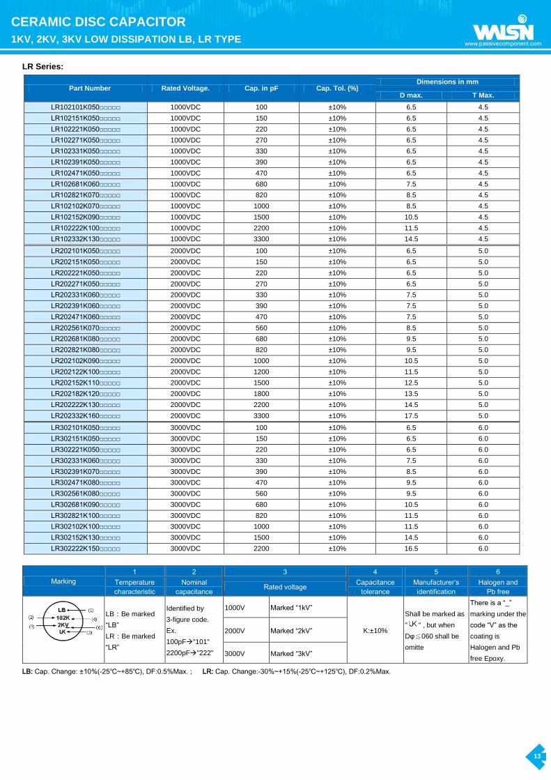
LR Series:
Part Number Rated Voltage. Cap. in pF Cap. Tol. (%) Dimensions in mm
D max. T Max.
LR102101K050□□□□□ 1000VDC 100 ±10% 6.5 4.5
LR102151K050□□□□□ 1000VDC 150 ±10% 6.5 4.5
LR102221K050□□□□□ 1000VDC 220 ±10% 6.5 4.5
LR102271K050□□□□□ 1000VDC 270 ±10% 6.5 4.5
LR102331K050□□□□□ 1000VDC 330 ±10% 6.5 4.5
LR102391K050□□□□□ 1000VDC 390 ±10% 6.5 4.5
LR102471K050□□□□□ 1000VDC 470 ±10% 6.5 4.5
LR102681K060□□□□□ 1000VDC 680 ±10% 7.5 4.5
LR102821K070□□□□□ 1000VDC 820 ±10% 8.5 4.5
LR102102K070□□□□□ 1000VDC 1000 ±10% 8.5 4.5
LR102152K090□□□□□ 1000VDC 1500 ±10% 10.5 4.5
LR102222K100□□□□□ 1000VDC 2200 ±10% 11.5 4.5
LR102332K130□□□□□ 1000VDC 3300 ±10% 14.5 4.5
LR202101K050□□□□□ 2000VDC 100 ±10% 6.5 5.0
LR202151K050□□□□□ 2000VDC 150 ±10% 6.5 5.0
LR202221K050□□□□□ 2000VDC 220 ±10% 6.5 5.0
LR202271K050□□□□□ 2000VDC 270 ±10% 6.5 5.0
LR202331K060□□□□□ 2000VDC 330 ±10% 7.5 5.0
LR202391K060□□□□□ 2000VDC 390 ±10% 7.5 5.0
LR202471K060□□□□□ 2000VDC 470 ±10% 7.5 5.0
LR202561K070□□□□□ 2000VDC 560 ±10% 8.5 5.0
LR202681K080□□□□□ 2000VDC 680 ±10% 9.5 5.0
LR202821K080□□□□□ 2000VDC 820 ±10% 9.5 5.0
LR202102K090□□□□□ 2000VDC 1000 ±10% 10.5 5.0
LR202122K100□□□□□ 2000VDC 1200 ±10% 11.5 5.0
LR202152K110□□□□□ 2000VDC 1500 ±10% 12.5 5.0
LR202182K120□□□□□ 2000VDC 1800 ±10% 13.5 5.0
LR202222K130□□□□□ 2000VDC 2200 ±10% 14.5 5.0
LR202332K160□□□□□ 2000VDC 3300 ±10% 17.5 5.0
LR302101K050□□□□□ 3000VDC 100 ±10% 6.5 6.0
LR302151K050□□□□□ 3000VDC 150 ±10% 6.5 6.0
LR302221K050□□□□□ 3000VDC 220 ±10% 6.5 6.0
LR302331K060□□□□□ 3000VDC 330 ±10% 7.5 6.0
LR302391K070□□□□□ 3000VDC 390 ±10% 8.5 6.0
LR302471K080□□□□□ 3000VDC 470 ±10% 9.5 6.0
LR302561K080□□□□□ 3000VDC 560 ±10% 9.5 6.0
LR302681K090□□□□□ 3000VDC 680 ±10% 10.5 6.0
LR302821K100□□□□□ 3000VDC 820 ±10% 11.5 6.0
LR302102K100□□□□□ 3000VDC 1000 ±10% 11.5 6.0
LR302152K130□□□□□ 3000VDC 1500 ±10% 14.5 6.0
LR302222K150□□□□□ 3000VDC 2200 ±10% 16.5 6.0
Marking
1 2 3 4 5 6
Temperature
characteristic
Nominal
capacitance Rated voltage
Capacitance
tolerance
Manufacturer’s
identification
Halogen and
Pb free
LB:Be marked
“LB”
LR:Be marked
“LR”
Identified by
3-figure code.
Ex.
100pF"101"
2200pF"222"
1000V Marked “1kV”
K:±10%
Shall be marked as
" " , but when
Dφ≦060 shall be
omitte
There is a “_”
marking under the
code “V” as the
coating is
Halogen and Pb
free Epoxy.
2000V Marked “2kV”
3000V Marked “3kV”
LB: Cap. Change: ±10%(-25℃~+85℃), DF:0.5%Max. ; LR: Cap. Change:-30%~+15%(-25℃~+125℃), DF:0.2%Max.

14
CERAMIC DISC CAPACITOR
1KV, 2KV, 3KV LOW DISSIPATION LB, LR TYPE
Caution
1. Caution (Rating):
1.1 Operating Voltage
When dc-rated capacitors are to be used in ac or ripple current circuits, be sure to maintain the Vp-p value of the applied voltage or the Vo-p which
contains dc bias within the rated voltage range.
When the voltage is applied to the circuit, starting or stopping may generate irregular voltage for a transit period because of resonance or switching.
Be sure to use a capacitor with a rated voltage range that includes these irregular voltages.
When using the low-dissipation (LB, LR Char.) series in a high-frequency and high-voltage circuit, be sure to read the instructions in item 4.
1.2 Operating Temperature And Self-Generated Heat
Keep the surface temperature of a capacitor below the upper limit of its rated operating temperature range. be sure to take into account the heat
generated by the capacitor itself. When the capacitor is used in a high-frequency current, pulse current or similar current, it may self-generate heat
due to dielectric loss. The applied voltage load (*) should be such that the capacitor's self-generated heat is within 20°c at an atmosphere temperature
of 25°c. When measuring, use a thermocouple of small thermal capacity-k of ø0.1mm in conditions where the capacitor is not affected by radiant heat
from other components or surrounding ambient fluctuations.
Excessive heat may lead to deterioration of the capacitor's characteristics and reliability. (Never attempt to perform measurement with the cooling fan
running. otherwise, accurate measurement cannot be ensured.)
1.3 Fail-Safe
When capacitor is broken, failure may result in a short circuit. Be sure to provide an appropriate fail-safe function like a fuse on your product if failure
would follow an electric shock, fire or fume.
1.4 Load Reduction and Self-generated Heat During
Application of High-frequency and High-voltage
Due to the low self-heating characteristics of low dissipation capacitors, the allowable electric power of these capacitors is generally much higher than
that of B characteristic capacitors. However, in case the self heating temperature is 15°C under a high-frequency voltage whose peak-to-peak value
equals the capacitor's rated voltage, the capacitor's power consumption may exceed it's allowable electric power.
Therefore, when using the Low D.F. series in a high-frequency and high-voltage circuit with a frequency of 1kHz or higher, make sure that the Vp-p
values including the DC bias, do not exceed the applied voltage value specified in Table 1. Also make sure that the self-heating temperature (the
difference between the capacitor's surface temperature and the capacitor's ambient temperature) at an ambient temperature of 25°C does not exceed
the value specified in Table 1.
As shown in Fig. 2, the self-heating temperature depends on the ambient temperature. Therefore, if you are not able to set the ambient temperature to
approximately 25°C, please contact our sales representatives or product engineers.
[Table 1] Allowable conditions at high frequency
Series DC rated voltage
Allowable conditions at High-frequency *3
Capacitor’s ambient temp. *2 Applied voltage (Max.)
Self-heating temp.
(25℃ambient temp.)*1
LB、LR
1KV 600Vp-p 15℃Max.
-25 ~ +125℃
1000Vp-p 5℃Max.
2KV 1000Vp-p 10℃Max.
2000Vp-p 5℃Max.
3KV 3000Vp-p 5℃Max.
1). Fig. 1 shows the relationship between the applied voltage and the allowable self-heating temperature regarding 1 to 3KV rated voltage of the low
D.F.series LB、LR characteristic.
2). Fig. 2 When the ambient temperature is 85 to 125℃, the applied voltage needs to be further reduced. If the low D.F. series needs o be used at an
ambient temperature of 85 to 125℃, please contact our sales representatives or product engineers.
3). Fig. 3 shows reference data on the allowable voltage-frequency characteristic for a sine wave voltage.Failure to follow the above cautions (items
1.1 to 1.4) may result, worst case, in a short circuit and cause fuming or partial dispersion when the product is used.

15
CERAMIC DISC CAPACITOR
1KV, 2KV, 3KV LOW DISSIPATION LB, LR TYPE
Fig 1: Relationship Between Applied Voltage and Self-heating Temperature
(Allowable Self-heating Temp. at 25℃ Ambient Temp.)
Fig 2: Dependence of Self-heating Temperature on Ambient Temperature
Fig 3: Allowable Voltage ( Sine Wave Voltage )- Frequency Characteristics (At Ambient Temperature of 85℃ or less)

16
CERAMIC DISC CAPACITOR
1KV, 2KV, 3KV LOW DISSIPATION LB, LR TYPE
Because of influence of harmonics, when the applied voltage is a rectangular wave or pulse wave voltage (instead of a sine wave voltage), the heat generated by the capacitor is higher than the value obtained by application of the sine wave with the same fundamental frequency. Roughly calculated for reference, the allowable voltage for a rectangular wave or pulse wave corresponds approximately to the allowable voltage for a sine wave whose fundamental frequency is twice as large as that of the rectangular wave or pulse wave. This allowable voltage, however, varies depending on the voltage and current waveforms. Therefore, you are requested to make sure that the self-heating temperature is not higher than the value specified in Table 1.
2. Caution (Storage And Operating Condition):
Operating And Storage Environment
The insulating coating of capacitors does not form a perfect seal; therefore, do not use or store capacitors in a corrosive atmosphere, especially where chloride gas, sulfide gas, acid, alkali, salt or the like are present. And avoid exposure to Moisture. Before cleaning, bonding or molding this product, verify that these processes do not affect product quality by testing the performance of a cleaned, bonded or molded product in the intended equipment. Store the capacitors where the temperature and relative humidity do not exceed –10 to 40 degrees centigrade and 15 to 85 %. Use capacitors within 6 months. Failure to follow the above cautions may result, worst case, in a short circuit and cause fuming or partial dispersion when the product is used.
3. Caution (Soldering And Mounting)
3.1 Vibration And Impact
Do not expose a capacitor or its leads to excessive shock or vibration during use.
3.2 Soldering
When soldering this product to a Pcb / Pwb, do not exceed the solder heat resistance specification of the capacitor. Subjecting this product to excessive heating could melt the internal junction solder and may result in thermal shocks that can crack the ceramic element. When soldering capacitor with a soldering iron, it should be performed in following conditions.
Temperature of iron-tip: 400 ℃ Max.
Soldering iron wattage: 50W Max. Soldering time: 3.5 sec. Max. Failure to follow the above cautions may result, worst case, in a short circuit and cause fuming or partial dispersion when the product is used.
4. Caution (Handling)
Vibration and Impact
Do not expose a capacitor or its leads to excessive shock or vibration during use. Failure to follow the above cautions may result, worst case, in a short circuit and cause fuming or partial dispersion when the product is used.
Notice
1. Notice (Soldering And Mounting)
Cleaning (Ultrasonic cleaning)
To perform ultrasonic cleaning, observe the following conditions. Rinse bath capacity: output of 20-watts per liter or less. Rinsing time: 5 min. Maximum. Do not vibrate the Pcb/Pwb directly. Excessive ultrasonic cleaning may lead to fatigue destruction of the lead wires.
2. Notice (Rating)
Low D.F. series
Capacitance might change greatly depending on the surrounding temperature or an applied voltage. So, it is not likely to be suitable for use in a time constant circuit. Please contact us if you need detailed information.

17
SAFETY STANDARD CERAMIC CAPACITOR
SAP Part Number Explanation
SAFETY STANDARD CERAMIC CAPACITOR SAP Part Number Explanation
To order, please also specify Pan Overseas Part No. as the following example for SAP system:
YV 0AC 472 M 10 0 L 20 C 7 H
1 2 3 4 5 6 7 8 9 10 11
1. Temperature characteristic (identified code):
CODE SL YP (Y5P) YU (Y5U) YV (Y5V)
Cap. Change (%) -1000~+350ppm/°C(+20°C~+85°C) ±10% +20%to -55% +30%to –80%
2. TYPE (identified by 3-figure code):
0AC=AC(X1-400V~/Y2-250V~); 1AC=AC(X1-440V~/Y2-300V~)(only approval for VDE//ENEC/UL/CSA)
0AH=AH(X1-400V~/Y1-250V~); 1AH=AH(X1-400V~/Y1-400V~)
0AS=AS(X1-760V~/Y1-500V~) (Only approval for VDE//ENEC/UL/CUL)
3. Capacitance (identified by 3-figure code)
4. Capacitance tolerance (identified by code)
5. Nominal body diameter dimension (identified by 2-figure code)
6. Internal control code:0—Normal, other code—Special control
7. Lead Style:
Lead type & Code Lead Configuration Lead type & Code Lead Configuration
Type B
Straight long lead
Lead style: B
Type X Outside kink lead
Lead style: X
Type D Vertical kink short lead
Lead style :D
Type L
Straight short lead
Lead style :L
8.Packing mode and lead length (identified by 2-figure code)
Taping Code Description Bulk Code Description
AM Box and Pitch:25.4 mm (10.0mm) 3E lead length L:3.5mm
AF Box and Pitch:15.0 mm (Pitch=7.5mm) 04 lead length L:4.0mm
4E lead length L:4.5mm
20 lead length L:20mm
9. Length tolerance 10. Pitch
Code Description Code Description
A ±0.5 mm (only for kink lead type) 7 7.5±1.0 mm
B ±1.0 mm 0 10±1.0 mm
C MIN. 11. Epoxy Resin Code
D Taping special purpose Code Description
H Halogen and Pb free, epoxy resin (Ag electrode)
T Halogen and Pb free, epoxy resin (Cu electrode)

18
SAFETY STANDARD CERAMIC CAPACITOR
AH and AS Type-Class X1/Y1; AC Type-Class X1/Y2
SAFETY STANDARD CERAMIC CAPACITOR:
AH and AS Type-Class X1/Y1; AC Type-Class X1/Y2
Introduction
Ideal for use as X/Y capacitors for AC line filters and primary-secondary coupling on switching power Supplies and AC adapters applications.
Having internationally recognized safety certifications, these capacitors are well-suited for applications that require keeping potentially disruptive or
damaging line transients and EMI out of susceptible equipment.
They are also an ideal solution in situations where there is a need to suppress line disturbances at the power.
Features
Compact size
Cost effective products
Ideal for across the line applications
Safety Standard Recognized for AC applications
Coated with flame-retardant epoxy resin (equivalent to UL94V-0 standards)
RoHS Compliance
Halogen free products are available
Approval standards
Agencies UL CSA CQC KTL VDE,ENEC, SEMKO,
NEMKO, DEMKO, FIMKO, SEV, KEMA
Standard No. UL60384-14:
2014 E60384-14:14
IEC60384-14:
2005 K60384-14 IEC384-14 4rd Edition
Rated Voltage
0AC = AC(X1:400V~/Y2:250V~)
1AC = AC(X1:440V~/Y2:300V~)
0AH = AH(X1:400V~/Y1:250V~)
1AH = AH(X1:400V~/Y1:400V~)
0AS = AS(X1:760V~/Y1:500V~)
Capacitance
Value(pF) AH: 2 ~ 4700; AC: 2 ~10000; AS: 100~4700
General specification
Capacitance Range
AH:10pF to 4700pF;
AC:10pF to 10000pF;
AS: 100pF to 4700pF
Capacitance Tolerance 0.25pF, 0. 5pF, 5%, 10%, 20%
Operating Temperature Range -40℃~ +125℃
Temperature Coefficient (△C Max) -1000~+350ppm/℃(SL), 10% (Y5P), +30 ~80% (Y5V), +20~55% (Y5U)
Voltage Resistance
AH Type: X1:400Vac / Y1:400Vac or 250Vac ;
AC Type: X1:400Vac or 440Vac / Y2:250VAC or 300Vac
AS Type: X1:760Vac / Y1:500Vac
Dissipation Factor(tanδ) or Q
SL: 30pF&above:Q≧1000 Below 30pF:Q≧400+20×C
@20℃, 1MHz, 10.2Vrms
Y5P: tanδ=2.5% Max. @20℃, 1KHz, 10.2Vrms
Y5U: tanδ=2.5% Max. @20℃, 1KHz, 10.2Vrms
Y5V: tanδ=5.0% Max. @20℃, 1KHz, 10.2Vrms
Insulation Resistance 10000MΩ at 500VDC for 60 Seconds
Dielectric Strength
1500VAC for 60 Seconds (AC TYPE) ( For Lead Pitch=5.0mm)
2600VAC for 60 Seconds (AC TYPE) ( For Lead Pitch=7.5 & 10 mm)
4000VAC for 60 Seconds (AH,AS TYPE) ( For Lead Pitch=10.0mm & 12.5mm)

19
SAFETY STANDARD CERAMIC CAPACITOR
AH and AS Type-Class X1/Y1; AC Type-Class X1/Y2
Typical characteristic curves & Z(Impedance) vs. frequency :
Note: Above data are just for reference not assured ones.
Leakage Current Characteristics (AH and AS: ~4000V / AC: ~2600V):
Note: Above data are just for reference not assured ones

20
SAFETY STANDARD CERAMIC CAPACITOR
Detail Specification
AH Type-Class X1/Y1 (Normal for standard parts):
Part Number Temp. Char.
Cap.(pF) Tol. Dimension (mm)
D Max. T Max. F±1 Wire Dia. (φd)
YP *AH101K060
Y5P
100
10%
7.0
5.0 10.0 0.550.05
YP *AH151K060 150 7.0
YP *AH221K060 220 7.0
YP *AH331K060 330 7.0
YP *AH471K070 470 8.0
YP *AH561K080 560 9.0
YP *AH681K080 680 9.0
YP *AH102K100 1000 11.0
YU *AH681M060
Y5U
680
20%
7.0
5.0 10.0 0.550.05
YU *AH102M070 1000 8.0
YU *AH152M080 1500 9.0
YU *AH222M090 2200 10.0
YU *AH332M110 3300 12.0
YU *AH392M120 3900 14.0
YU *AH472M130 4700 14.0
YV *AH102M060
Y5V
1000
20%
7.0
5.5 10.0 0.550.05
YV *AH152M070 1500 8.0
YV *AH222M080 2200 9.0
YV *AH332M100 3300 11.0
YV *AH472M110 4700 12.0
SL *AH ***J060
SL
10,12,15,18,20,22,24,27,30,33,36,39
5%
7.0
5.0 10.0 0.550.05 SL *AH ***J070 47,50,51,56,62 8.0
SL *AH ***J080 68,75 9.0
SL *AH***J090 82,100 10.0
AS Type-Class X1/Y1 (Normal for standard parts):
SAP P/N T.C. Capacitance(pF) Tolerance Dimension (unit:mm)
D(max.) T(max.) F Φd
YP*AS101K070*
Y5P
100 pF
±10%
8.0
7.0 10.0 0.55+/-0.05
YP*AS151K070* 150 pF 8.0
YP*AS221K070* 220 pF 8.0
YP*AS331K070* 330 pF 8.0
YP*AS471K080* 470 pF 9.0
YP*AS561K090* 560 pF 10.0
YP*AS681K090* 680 pF 10.0
YP*AS102K110* 1000 pF 12.0
YU*AS102M080*
Y5U
1000 pF
±20%
9.0
YU*AS152M090* 1500 pF 10.0
YU*AS222M120* 2200 pF 13.0
YU*AS332M120* 3300 pF 13.0
YU*AS392M130* 3900 pF 14.0
YU*AS472M140* 4700 pF 15.0

21
SAFETY STANDARD CERAMIC CAPACITOR
Detail Specification
AC Type-Class X1/Y2:
Part Number Temp.
Char. Cap.(pF) Tol.
Dimension (mm)
D max. T max. F±1
Wire Dia. (φd)
YP *AC101K060
Y5P
100
10%
7.0
5.0
7.5,
10.0
0.55±0.05
YP *AC151K060 150 7.0
YP *AC221K060 220 7.0
YP *AC331K060 330 7.0
YP *AC471K060 470 7.0
YP *AC561K070 560 8.0
YP *AC681K070 680 8.0
YP *AC821K080 820 9.0
YP *AC102K080 1000 9.0
YU *AC102M060
Y5U
1000
20%
7.0
5.0
7.5
10.0
0.55±0.05
YU *AC152M080 1500 9.0
YU *AC222M080 2200 9.0
YU *AC332M100 3300 11.0
YU *AC392M120 3900 13.0
YU *AC472M120 4700 13.0
YV *AC102M060
Y5V
1000
20%
7.0
5.0
7.5
10.0 0.55±0.05
YV *AC152M060 1500 7.0
YV *AC222M060 2200 7.0
YV *AC332M080 3300 9.0
YV *AC392M100 3900 11.0
YV *AC472M100 4700 11.0
YV *AC682M120 6800 13.0
YV *AC103M140 10000 15.0 10.0
SL *AC *** J060
SL
10,12,15,18,20,22,24,27,
30,33,36,39,47,50,51
5%
7.0
5.0 7.5
10.0 0.55±0.05 SL *AC *** J070 56,62,68,75 8.0
SL *AC820J080 82 9.0
SL *AC101J090 100 10.0
= Lead Code:Please consult our part number explanation on page 20 for detail lead space, lead length, and lead configuration.

22
SAFETY STANDARD CERAMIC CAPACITOR
Taping Specification and Dimension
Taping Format: AH and AS X1/Y1
25.4mm pitch/lead spacing 10.0mm taping
Lead Code: *BAMD0 & *DAMD0 & *XAMD0
*B* *D* *X*
POE Part Number *BAMD0 / *DAMD0 / *XAMD0
Item Symbol Dimensions(mm)
Pitch of component P 25.4 ± 2
Pitch of sprocket P0 12.7 ± 0.3
Lead spacing F 10.0 ± 1.0
Length from hole center to component center P2 12.7 ± 1.5
Length from hole center to lead P1 7.7 ± 1.5
Body diameter D Refer to page 21
Deviation along tape, life or right △S 0 ± 2.0
Carrier tape width W 18.0 +1/ -0.5
Position of sprocket hole W1 9.0 ± 0.5
Lead distance between the kink and center of sprocket hole H0 18.0 +2.0/-0
(For: *DAMD0 & *XAMD0)
Lead distance between the bottom of body and the center
of sprocket hole H
20.0+1.5/-1.0
(For: *BAMD0)
Protrusion length 2.0max (Or the end of lead wire may be inside the tape.)
Diameter of sprocket hole D0 4.0 ± 0.2
Lead diameter φd 0.55±0.05
Total tape thickness t1 0.6 ± 0.3
Total thickness, tape and lead wire t2 1.5 max.
Deviation across tape △h1 2.0 max.
△h2 2.0 max
Portion to cut in case of defect L 11.0 max.
Hole-down tape width W0 8.0 min
Hole-down tape distortion W2 1.5 ± 1.5
Coating extension on leads E 3.0 max for straight lead style; Not exceed the kink leads for kink lead.
Body thickness T Refer to page 20
23
SAFETY STANDARD CERAMIC CAPACITOR
Taping Specification and Dimension
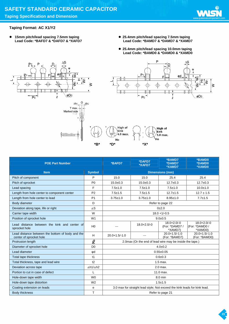
Taping Format: AC X1/Y2
15mm pitch/lead spacing 7.5mm taping
Lead Code: *BAFD7 & *DAFD7 & *XAFD7
25.4mm pitch/lead spacing 7.5mm taping Lead Code: *BAMD7 & *DAMD7 & *XAMD7
25.4mm pitch/lead spacing 10.0mm taping
Lead Code: *BAMD0 & *DAMD0 & *XAMD0
*B* *D* *X*
POE Part Number *BAFD7 *DAFD7 *XAFD7
*BAMD7 *DAMD7 *XAMD7
*BAMD0 *DAMD0 *XAMD0
Item Symbol Dimensions (mm)
Pitch of component P 15.0 15.0 25.4 25.4
Pitch of sprocket P0 15.0±0.3 15.0±0.3 12.7±0.3 12.7±0.3
Lead spacing F 7.5±1.0 7.5±1.0 7.5±1.0 10.0±1.0
Length from hole center to component center P2 7.5±1.5 7.5±1.5 12.7±1.5 12.7 ± 1.5
Length from hole center to lead P1 3.75±1.0 3.75±1.0 8.95±1.0 7.7±1.5
Body diameter D Refer to page 22
Deviation along tape, life or right △S 0±2.0
Carrier tape width W 18.0 +1/-0.5
Position of sprocket hole W1 9.0±0.5
Lead distance between the kink and center of sprocket hole
H0 --- 18.0+2.0/-0
18.0+2.0/-0 (For: *DAMD7 /
*XAMD7)
18.0+2.0/-0 (For: *DAMD0 /
*XAMD0)
Lead distance between the bottom of body and the center of sprocket hole
H 20.0+1.5/-1.0 --- 20.0+1.5/-1.0
(For: *BAMD7) 20.0+1.5/-1.0
(For: *BAMD0)
Protrusion length 2.0max (Or the end of lead wire may be inside the tape.)
Diameter of sprocket hole D0 4.0±0.2
Lead diameter φd 0.55±0.05
Total tape thickness t1 0.6±0.3
Total thickness, tape and lead wire t2 1.5 max.
Deviation across tape △h1/△h2 2.0 max.
Portion to cut in case of defect L 11.0 max.
Hole-down tape width W0 8.0 min
Hole-down tape distortion W2 1.5±1.5
Coating extension on leads e 3.0 max for straight lead style; Not exceed the kink leads for kink lead.
Body thickness T Refer to page 21

24
SAFETY STANDARD CERAMIC CAPACITOR
Marking
Marking: AH
1. Type Designation AH
2. .Nominal Capacitance 3-digit-system
3. Capacitance Tolerance D:±0.5pF, J:±5%, K:±10%, M:±20%
4. Company Trade mark
5. Products ID
Abbreviation ex.:
6. Approved Monogram:
(1) VDE approval mark
IEC 60384-14
Class Code:X1:400V~,Y1:250V~ or400V~
(2) UL approval mark
(6) DEMKO approval mark
(3) CSA approval mark
(7) FIMKO approval mark
(4) SEMKO approval mark
(8) SEV approval mark
(5) NEMKO approval mark
(9) CQC approval mark
Two sides
(For SAP part number 10-11 digits≤07 products)
One side
(For SAP part number 10-11 digits≥“08” products)
Ex.:
Ex.:
Special marking: YP*AH102K100* 0AH:
1AH:
* Marking by the laser.
*“C”: Marked with code “ _ ” stand for Halogen and Pb free for epoxy resin coating.

25
SAFETY STANDARD CERAMIC CAPACITOR
Marking
Marking: AC
1. Type Designation AC
2. Nominal Capacitance 3-digit-system
3. Capacitance Tolerance D:±0.5pF, J:±5%, K:±10%, M:±20%
4. Company Trade mark
5. Products ID
Abbreviation ex.:
6. Approved monogram:
6.1 VDE or
6.3 CSA
6.5 NEMKO
6.7 FIMKO
6.9 CQC
6.2 UL
6.4 SEMKO
6.6 DEMKO
6.8 SEV
Marking Ex.:
Type Two sides marking
(For SAP part number 10-11 digits≤07 products)
One side marking
(For SAP part number 10-11
digits≥“08” products)
0AC X1:400Vac Y2:250Vac
1AC
X1:440Vac Y2:300Vac
*Marking by the laser. *“C”:Marked with code “ _ ” stand for Halogen and Pb free for epoxy resin coating.

26
SAFETY STANDARD CERAMIC CAPACITOR
Marking
Marking: AS
1. Type Designation AS
2. Nominal Capacitance 3-digit-system
3. Capacitance Tolerance K:±10%, M:±20%
4. Company Name Code(Trade mark)
5. Products ID Abbreviation ex.:
6. Approved Monogram:
(1) VDE approval mark
IEC 60384-14
Class code:X1:760V~,Y1:500V~
(2) UL approval mark or
Marking sample
Two sides marking
(for SAP part number 10-11 digits ≤“08 ”products)
One side marking
(for SAP part number 10-11 digits ≥“09” products)
* Marking by the laser.
*“C”:Marked with code “ _ ” stand for Halogen and Pb free epoxy resin.
27
RADIAL LEADED MULTILAYER CERAMIC CAPACITOR
SAP Part Number Explanation
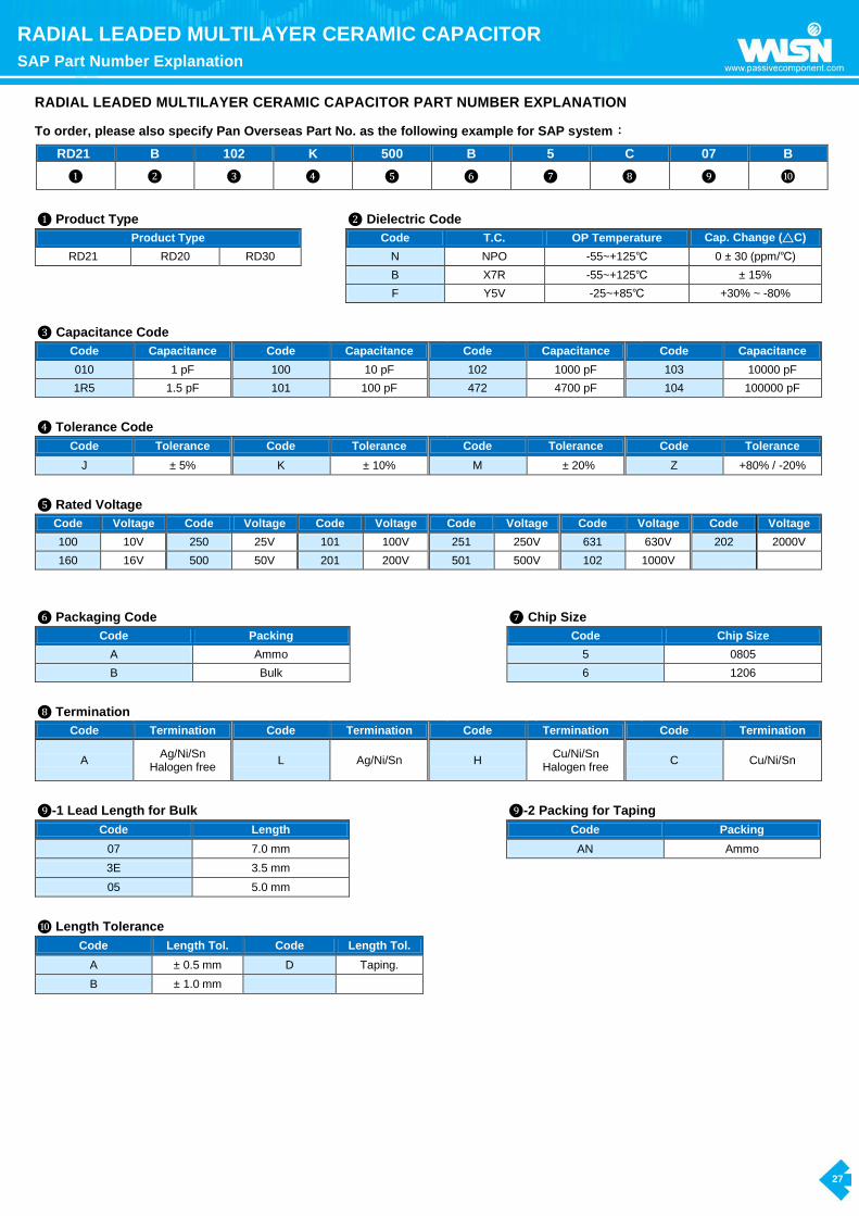
RADIAL LEADED MULTILAYER CERAMIC CAPACITOR PART NUMBER EXPLANATION
To order, please also specify Pan Overseas Part No. as the following example for SAP system:
RD21 B 102 K 500 B 5 C 07 B
❶ ❷ ❸ ❹ ❺ ❻ ❼ ❽ ❾ ❿
❶ Product Type ❷ Dielectric Code
Product Type Code T.C. OP Temperature Cap. Change (△C)
RD21 RD20 RD30 N NPO -55~+125℃ 0 ± 30 (ppm/℃)
B X7R -55~+125℃ ± 15%
F Y5V -25~+85℃ +30% ~ -80%
❸ Capacitance Code
Code Capacitance Code Capacitance Code Capacitance Code Capacitance
010 1 pF 100 10 pF 102 1000 pF 103 10000 pF
1R5 1.5 pF 101 100 pF 472 4700 pF 104 100000 pF
❹ Tolerance Code
Code Tolerance Code Tolerance Code Tolerance Code Tolerance
J ± 5% K ± 10% M �± 20% Z +80% / -20%
❺ Rated Voltage
Code Voltage Code Voltage Code Voltage Code Voltage Code Voltage Code Voltage
100 10V 250 25V 101 100V 251 250V 631 630V 202 2000V
160 16V 500 50V 201 200V 501 500V 102 1000V
❻ Packaging Code ❼ Chip Size
Code Packing Code Chip Size
A Ammo 5 0805
B Bulk 6 1206
❽ Termination
Code Termination Code Termination Code Termination Code Termination
A Ag/Ni/Sn
Halogen free L Ag/Ni/Sn H
Cu/Ni/Sn Halogen free
C Cu/Ni/Sn
❾-1 Lead Length for Bulk ❾-2 Packing for Taping
Code Length Code Packing
07 7.0 mm AN Ammo
3E 3.5 mm
05 5.0 mm
❿ Length Tolerance
Code Length Tol. Code Length Tol.
A ± 0.5 mm D Taping.
B ± 1.0 mm

28
RADIAL LEADED MULTILAYER CERAMIC CAPACITOR
Features, Dimension and Taping Specification
Features
1. MLC Radial Lead Capacitor (RD) has wide application in computer, data processing, telecommunication, industrial control and instrumentation equipment.
2. The radial lead MLC is built with superior moisture, and shock resistant epoxy coating material, can be supplied in both, bulk or taping form for automatic insertion.
3. RoHS compliance. 4. Halogen free products are available.
Lead configuration and dimension
(Unit: mm)
Size Width
(W) Max. Height (H)Max.
Thickness (T) Max.
Length (L)
Lead spacing (F) Lead diameter (d) Taping Bulk
RD20 0805 5.0 4.5 6.0
Refer to the item -1 SAP Part
Number
2.5±1.0 2.54±1.0
0.5±0.05 RD21
0805 5.0 4.5 6.5
5.0±1.0 5.08±1.0 1206 6.5 5.0 7.0
1210 6.5 5.5 7.5
RD30 1808 8.0 6.0 7.5
5.0±1.0 5.08±1.0 1812 8.0 6.5 8.0
Lead
Configuration
RD20 RD21 RD30
Taping Specification
ITEM SYMBOL DIMENSIONS (mm) REMARKS
Pitch of Components P 12.7 1.0
Feed hole pitch P0 12.7 0.3 Cumulative pitch error: 1.0mm / 20 pitches
Feed hole center to lead P1 5.1 0.7(for RD20)
3.85 0.7(for RD21)
Feed hole center to component center P2 6.35 1.3
Lead diameter φd 0.5 0.05
Lead to lead spacing F 2.5 0.8 (for RD20) 5.0 0.8 (for RD21) 5.0 0.8 (for RD30)
To lead top within tolerance
Component alignment, F - R △h 2.0 max The alignment from the center of the lead is 1.0 mm
Tape width W 18.0 -1.0 / -0.5
Adhesive tape width W0 11.0 min
Hole position W1 9.0 0.5
Adhesive tape position W2 3.0 max
Height of bottom body from tape center H 18.0 + 2.0 / -0 H + 12.5 mm ≦ H1
Lead-wire clinch height H0 18.0 0.5 (for RD20/RD30)
16.0 0.5 (for RD21) 6.5 ≦ H0 - W1
Component height H1 32.25 max
Feed hole diameter D0 4.0 0.2
Total tape thickness T 0.6 0.3

29
RADIAL LEADED MULTILAYER CERAMIC CAPACITOR
Capacitance Range
NPO Dielectric
Dielectric NPO
Size 0805 1206 1210 1808 1812
Voltage (VDC) 50 100 200 50 100 200 250 500 630 1000 50 100 200 250 500 630 1000 500 630 1000 2000 500 630 1000 2000
Capacitance
1.0pF (010) B B B
1.2pF (1R2) B B B B B
1.5pF (1R5) B B B B B B B B B B
1.8pF (1R8) B B B B B B B B B B B B B B
2.2pF (2R2) B B B B B B B B B B B B B B
2.7pF (2R7) B B B B B B B B B B B B B B
3.3pF (3R3) B B B B B B B B B B B B B B
3.9pF (3R9) B B B B B B B B B B B B B B
4.7pF (4R7) B B B B B B B B B B B B B B
5.6pF (5R6) B B B B B B B B B B B B B B
6.8pF (6R8) B B B B B B B B B B B B B B
8.2pF (8R2) B B B B B B B B B B B B B B
10pF (100) B B B B B B B B B B B B B B B B B B B B B B B B B
12pF (120) B B B B B B B B B B B B B B B B B B B B B B B B B
15pF (150) B B B B B B B B B B B B B B B B B B B B B B B B B
18pF (180) B B B B B B B B B B B B B B B B B B B B B B B B B
22pF (220) B B B B B B B B B B B B B B B B B B B B B B B B B
27pF (270) B B B B B B B B B B B B B B B B B B B B B B B B B
33pF (330) B B B B B B B B B B B B B B B B B B B B B B B B B
39pF (390) B B B B B B B B B B B B B B B B B B B B B B B B B
47pF (470) B B B B B B B B B B B B B B B B B B B B B B B B B
56pF (560) B B B B B B B B B B B B B B B B B B B B B B B B B
68pF (680) B B B B B B B B B B B B B B B B B B B B B B B B B
82pF (820) B B B B B B B B B B B B B B B B B B B B B B B B B
100pF (101) B B B B B B B B B B B B B B B B B B B B B B B B B
120pF (121) B B B B B B B B B B B B B B B B B B B B B B B B B
150pF (151) B B B B B B B B B B B B B B B B B B B B B B B B B
180pF (181) B B B B B B B B B B B B B B B B B B B B B B B B B
220pF (221) B B B B B B B B B B B B B B B B B B B B B B B B B
270pF (271) B B B B B B B B B B B B B B B B B B B B B B B B B
330pF (331) B B B B B B B B B B B B B B B B B B B B B B B B B
390pF (391) B B B B B B B B B B B B B B B B B B B B B B B B
470pF (471) B B B B B B B B B B B B B B B B B B B B B B B B
560pF (561) B B B B B B B B B B B B B B B B B B B B B B B
680pF (681) B B B B B B B B B B B B B B B B B B B B B B B
820pF (821) B B B B B B B B B B B B B B B B B B B B B B B
1000pF (102) B B B B B B B B B B B B B B B B B B B B B B B
1200pF (122) B B B B B B B B B B B B B B B B B B B B
1500pF (152) B B B B B B B B B B B B B B B B B B B B
1800pF (182) B B B B B B B B B B B B B B B B B B B
2200pF (222) B B B B B B B B B B B B B B B B B B B
2700pF (272) B B B B B B B B B B B B B B
3300pF (332) B B B B B B B B B B B B B B
3900pF (392) B B B B B B B B B B B B
4700pF (472) B B B B B B B B B B
5600pF (562) B B B B B B B B
6800pF (682) B B B B B B B B
8200pF (822) B B B B B B B
0.010uF (103) B B B B B B B
0.012uF (123) B B B B B
0.015uF (153) B B B B
0.018uF (183) B B B
0.022uF (223) B B B
0.027uF (273) B
0.033uF (333) B
0.039uF (393) B
0.047uF (473) B
0.056uF (563) B
0.068uF (683) B
0.082uF (823) B
0.1uF (104) B
1. The letter in cell is expressed the symbol of product terminations. B: (Cu/Ni/Sn)
2. RD30 type can use Mlcc size 1808 and 1812, RD21 type can use Mlcc size 0805 and 1206, but RD20 type can only use Mlcc size 0805.

30
RADIAL LEADED MULTILAYER CERAMIC CAPACITOR
Capacitance Range
X7R Dielectric
Dielectric X7R
Size 0805 1206 1210 1808 1812
Voltage (VDC) 50 100 200 50 100 200 250 500 630 1000 50 100 200 250 500 630 1000 500 630 1000 2000 3000 500 630 1000 2000 3000
Capacitance
100pF (101) B B B
120pF (121) B B B
150pF (151) B B B B B B B B B B B B B B B
180pF (181) B B B B B B B B B B B B B B B
220pF (221) B B B B B B B B B B B B B B B
270pF (271) B B B B B B B B B B B B B B B B B
330pF (331) B B B B B B B B B B B B B B B B B
390pF (391) B B B B B B B B B B B B B B B B B
470pF (471) B B B B B B B B B B B B B B B B B
560pF (561) B B B B B B B B B B B B B B B B B
680pF (681) B B B B B B B B B B B B B B B B B B
820pF (821) B B B B B B B B B B B B B B B B B B
1000pF (102) B B B B B B B B B B B B B B B B B B B B B B B B B B B
1200pF (122) B B B B B B B B B B B B B B B B B B B B B B B B B B B
1500pF (152) B B B B B B B B B B B B B B B B B B B B B B B B B B B
1800pF (182) B B B B B B B B B B B B B B B B B B B B B B B B B B B
2200pF (222) B B B B B B B B B B B B B B B B B B B B B B B B B B
2700pF (272) B B B B B B B B B B B B B B B B B B B B B B B B B B
3300pF (332) B B B B B B B B B B B B B B B B B B B B B B B B B B
3900pF (392) B B B B B B B B B B B B B B B B B B B B B B B B B
4700pF (472) B B B B B B B B B B B B B B B B B B B B B B B B B
5600pF (562) B B B B B B B B B B B B B B B B B B B B B B B B
6800pF (682) B B B B B B B B B B B B B B B B B B B B B B B
8200pF (822) B B B B B B B B B B B B B B B B B B B B B B B
0.01uF (103) B B B B B B B B B B B B B B B B B B B B B B B
0.012uF (123) B B B B B B B B B B B B B B B B B B B B B B B
0.015uF (153) B B B B B B B B B B B B B B B B B B B B B B B
0.018uF (183) B B B B B B B B B B B B B B B B B B B B B
0.022uF (223) B B B B B B B B B B B B B B B B B B B B B
0.027uF (273) B B B B B B B B B B B B B B B B B B B B
0.033uF (333) B B B B B B B B B B B B B B B B B B B B
0.039uF (393) B B B B B B B B B B B B B B B B B B B B
0.047uF (473) B B B B B B B B B B B B B B B B B B B B
0.056uF (563) B B B B B B B B B B B B B B B B B B B
0.068uF (683) B B B B B B B B B B B B B B B B B
0.082uF (823) B B B B B B B B B B B B B B B
0.1uF (104) B B B B B B B B B B B B B B B
0.12uF (124) B B B B B B B B B
0.15uF (154) B B B B B B B B B
0.18uF (184) B B B B B B B B B
0.22uF (224) B B B B B B B B B B
0.27uF (274) B B B B B B B
0.33uF (334) B B B B B B B
0.39uF (394) B B B B B B B
0.47uF (474) B B B B B B B B
0.56uF (564) B B B B
0.68uF (684) B B B B
0.82uF (824) B B B B
1.0uF (105) B B B B B
1.5uF (155) B B
2.2uF (225) B B B B B
4.7uF (475) B B
1. The letter in cell is expressed the symbol of product terminations. B: (Cu/Ni/Sn)
2. RD30 type can use Mlcc size 1808 and 1812, RD21 type can use Mlcc size 0805 and 1206, but RD20 type can only use Mlcc size 0805.

31
RADIAL LEADED MULTILAYER CERAMIC CAPACITOR
Capacitance Range and Marking
Y5V Dielectric
Dielectric Y5V
Size 0805 1206 1210 1812
Voltage (VDC) 10 16 25 50 100 200 10 16 25 50 100 200 250 10 16 25 50 100 200 250 50 100 200 250
Capacitance
0.01uF (103) B B B B B B B B B B B B B B B B B B B
0.015uF (153) B B B B B B B B B B B B B B B B B B B
0.022uF (223) B B B B B B B B B B B B B B B B B B B
0.033uF (333) B B B B B B B B B B B B B B B B B B B
0.047uF (473) B B B B B B B B B B B B B B B B B B B
0.068uF (683) B B B B B B B B B B B B B B B B B B B
0.1uF (104) B B B B B B B B B B B B B B B B B B B B B B B
0.15uF (154) B B B B B B B B B B B B B B B B B B B B B B
0.22uF (224) B B B B B B B B B B B B B B B B B B
0.33uF (334) B B B B B B B B B B B B B B B B B
0.47uF (474) B B B B B B B B B B B B B B B B
0.68uF (684) B B B B B B B B B B B B B B B B
1.0uF (105) B B B B B B B B B B B B B B
1.5uF (155) B B B B B B B B B
2.2uF (225) B B B B B B B B B B B B
3.3uF (335) B B B B B B B B B
4.7uF (475) B B B B B B B B B B B
6.8uF (685) B B B B B B B B
10uF (106) B B B B B B B B B B
22uF (226) B B
☆ The letter in cell is expressed the symbol of product terminations. B: (Cu/Ni/Sn)
☆ RD30 type can use Mlcc size 1808 and 1812, RD21 type can use Mlcc size 0805 and 1206, but RD20 type can only use Mlcc size 0805.
Marking
Rated
voltage
(VDC)
10 16 25 50 100 200 250 500 630 1000 2000 3000
Marking
104
104
104
104
104
104
104
104
104
104
104
104
1. Rated capacitance: Identified by 3-figure code.
2. Halogen and Pb free: There is a “.” beside the capacitance code when the coating resin is Halogen and Pb free Epoxy.

32
MPQ (Min. Packing Quantity)
MPQ (Min. Packing Quantity)
Y Cap. (AH and AC
series)
Packing type
The code of 14th to 15th in SAP P/N MPQ
(Kpcs/Box) Remark
Taping
AF 1
AT 0.5
AM 1 For size code≦11
AM 0.5 For size code≧12
AN 1
Packing type
Lead length Size code of 10th to
11th in SAP P/N MPQ
(Kpcs/Bag) Kpcs/Box Remark
Bulk
Long lead
(L≧20mm)
06~12 0.5 1.5
13-15 0.5 1
Short lead
(L<20mm)
06~14 0.5 2
15 0.2 1
All 16 0.2 1
Disc DC Cap. (50V~6KVdc)
Packing type
The code of 14th to 15th in SAP P/N MPQ
(Kpcs/Box) Remark
Taping
AF 1
AT 0.5
AM 0.5
TN 2
AN 2 Phenolic resin
AN 1.5 Epoxy resin
Packing type
Lead length Size code of 10th to
12th in SAP P/N MPQ
(Kpcs/Bag) Kpcs/Box Remark
Bulk
Long lead (L≧20mm)
040~070 1 3 Phenolic resin
080~100 1 2 Phenolic resin
050~100 1 2 Epoxy resin
110~120 0.5 1.5
130~170 0.5 1
Short lead
(L<20mm)
040~060 1 6
070~080 1 4
090~100 1 3
110~140 1 2
150~170 0.5 1
RD Cap. (Multilayer
Radial Leaded Type)
Packing type
The code of 16th to 17th in SAP P/N MPQ
(Kpcs/Box) Remark
Taping
TN 2
AN 2 Size of chip≦0805
AN 1.5 Size of chip>0805
Packing type
Lead length MPQ
(Kpcs/Bag) Kpcs/Box Remark
Bulk Short lead(L<20mm) 1 20

33
PLAN & MEMO