TABLE OF CONTENTS PART PART 2 OF 5: ARCHITECTURAL …
172
TABLE OF CONTENTS PART PART 2 OF 5: ARCHITECTURAL WORKS DIVISION 4 -MASONRY SECTION 04065 -MASONRY MORTAR AND GROUT SECTION 04810 - UNIT MASONRY ASSEMBLIES DIVISION 5 -METALS SECTION 05120 - STRUCTURAL STEEL SECTION 05500 -METAL FABRICATIONS DIVISION 6 -WOOD AND PLASTICS SECTION 06200 - FINISH CARPENTRY SECTION 06410 - CUSTOM CABINETS DIVISION 7 - THERMAL AND MOISTURE PROTECTION SECTION 07130 - SHEET WATERPROOFING SECTION 07140 - FLUID-APPLIED WATERPROOFING SECTION 07212 - BOARD INSULATION SECTION 07260 - VAPOR RETARDERS SECTION 07270 - AIR BARRIERS SECTION 07620 - SHEET METAL FLASHING AND TRIM SECTION 07900 - JOINT SEALERS DIVISION 8 - DOORS AND WINDOWS SECTION 08114 - STANDARD STEEL DOORS SECTION 08115 - STANDARD STEEL FRAMES SECTION 08212 - FLUSH WOOD DOORS SECTION 08310 - ACCESS DOORS AND PANELS SECTION 08520 - ALUMINUM DOORS AND WINDOWS SECTION 08710 - DOOR HARDWARE SECTION 08800 – GLAZING DIVISION 9 - FINISHES SECTION 09220 - PORTLAND CEMENT PLASTER SECTION 09300 - TILE SECTION 09632 - STONE FLOORING SECTION 09900 - PAINTS AND COATINGS _________________________
Transcript of TABLE OF CONTENTS PART PART 2 OF 5: ARCHITECTURAL …

TABLE OF CONTENTS
PART PART 2 OF 5: ARCHITECTURAL WORKS
DIVISION 4 -MASONRY
SECTION 04065 -MASONRY MORTAR AND GROUT
SECTION 04810 - UNIT MASONRY ASSEMBLIES
DIVISION 5 -METALS
SECTION 05120 - STRUCTURAL STEEL
SECTION 05500 -METAL FABRICATIONS
DIVISION 6 -WOOD AND PLASTICS
SECTION 06200 - FINISH CARPENTRY
SECTION 06410 - CUSTOM CABINETS
DIVISION 7 - THERMAL AND MOISTURE PROTECTION
SECTION 07130 - SHEET WATERPROOFING
SECTION 07140 - FLUID-APPLIED WATERPROOFING
SECTION 07212 - BOARD INSULATION
SECTION 07260 - VAPOR RETARDERS
SECTION 07270 - AIR BARRIERS
SECTION 07620 - SHEET METAL FLASHING AND TRIM
SECTION 07900 - JOINT SEALERS
DIVISION 8 - DOORS AND WINDOWS
SECTION 08114 - STANDARD STEEL DOORS
SECTION 08115 - STANDARD STEEL FRAMES
SECTION 08212 - FLUSH WOOD DOORS
SECTION 08310 - ACCESS DOORS AND PANELS
SECTION 08520 - ALUMINUM DOORS AND WINDOWS
SECTION 08710 - DOOR HARDWARE
SECTION 08800 – GLAZING
DIVISION 9 - FINISHES
SECTION 09220 - PORTLAND CEMENT PLASTER
SECTION 09300 - TILE
SECTION 09632 - STONE FLOORING
SECTION 09900 - PAINTS AND COATINGS
_________________________

SECTION 04065
MASONRY MORTAR AND GROUT
PART 1 GENERAL
1.1.1 SUMMARY
A. Section includes mortar and grout for masonry.
B. Related Sections:
1. Section 04810 - Unit Masonry Assemblies: Installation of mortar and grout.
2. Section 04853 - Mortar Placed Stone Assemblies.
3. Section 08115 - Standard Steel Frames.
1.2 REFERENCES
A. ASTM International:
1. ASTM C5 - Standard Specification for Quicklime for Structural Purposes.
2. ASTM C91 - Standard Specification for Masonry Cement.
3. ASTM C94 - Standard Specification for Ready-Mixed Concrete.
4. ASTM C143/C143M - Standard Test Method for Slump of Hydraulic Cement
Concrete.
5. ASTM C144 - Standard Specification for Aggregate for Masonry Mortar.
6. ASTM C150 - Standard Specification for Portland Cement.
7. ASTM C199 - Standard Test Method for Pier Test for Refractory Mortars.
8. ASTM C207 - Standard Specification for Hydrated Lime for Masonry Purposes.
9. ASTM C270 - Standard Specification for Mortar for Unit Masonry.
10. ASTM C387 - Standard Specification for Packaged, Dry, Combined Materials f
or Mortar and Concrete.
11. ASTM C404 - Standard Specification for Aggregates for Masonry Grout.
12. ASTM C476 - Standard Specification for Grout for Masonry.
13. ASTM C595M - Standard Specification for Blended Hydraulic Cements
(Metric).
14. ASTM C780 - Standard Test Method for Preconstruction and Construction
Evaluation of Mortars for Plain and Reinforced Unit Masonry.
15. ASTM C1019 - Standard Test Method for Sampling and Testing Grout.
16. ASTM C1142 - Standard Specification for Extended Life Mortar for Unit
Masonry.
17. ASTM C1314 - Standard Test Method for Constructing and Testing Masonry
Prisms Used to Determine Compliance with Specified Compressive Strength of
Masonry.
18. ASTM C1329 - Standard Specification for Mortar Cement.
19. ASTM C1357 - Standard Test Method for Evaluating Masonry Bond Strength.
B. The Masonry Society:
1. TMS MSJC - Building Code for Masonry Structures (ACI 530/ASCE 5/TMS
402), Specification for Masonry Structures (ACI 530.1/ASCE 6/TMS 602) and
Commentaries.

1.3 SUBMITTALS
A. General Requirements: Requirements for submittal procedures.
B. Samples: Submit two samples of mortar, illustrating mortar color and color range.
C. Design Data: Submit design mix when Property specification of ASTM C270 is to be
used, required environmental conditions, and admixture limitations.
D. Test Reports:
1. Submit reports on mortar indicating conformance of mortar to property
requirements of ASTM C270 mortar to requirements of ASTM C1142
component mortar materials to requirements of ASTM C270 and test and
evaluation reports to ASTM C780 for aggregate ratio and water content, air
content, consistency and compressive strength.
2. Submit reports on grout indicating conformance of grout to property
requirements of ASTM C476, component grout materials to requirements of
ASTM C476 and test and evaluation reports to ASTM C1019.
E. Manufacturer's Installation Instructions: Submit premix mortar manufacturer's installation
instructions.
F. Manufacturer's Certificate: Certify products meet or exceed specified requirements.
1.4 QUALITY ASSURANCE
A. Perform Work in accordance with TMS MSJC Code and TMS MSJC Specification.
B. Maintain one copy of each document on site.
1.5 ENVIRONMENTAL REQUIREMENTS
A. General Requirements: Product requirements.
B. Hot and Cold Weather Requirements: TMS MSJC Specification.
PART 2 PRODUCTS
2.1 MORTAR AND MASONRY GROUT
A. Manufacturer: Any internationally recognized manufacturer having an official
technical agreement to conformity with standards for the product.
2.2 COMPONENTS
A. Portland Cement: ASTM C150, Type I, gray color.
B. Mortar Aggregate: ASTM C144, standard masonry type.

C. Grout Aggregate: ASTM C404, fine and/or coarse.
C. Water: Clean and potable.
E. Calcium chloride is not permitted.
2.3 MIXES
A. Mortar Mixes:
1. Mortar for Structural Masonry: ASTM C270, Type M, S, or N, using
Proportion specification.
2. Mortar for Non-Structural Masonry: ASTM C270, Type M, S, N, or O, using
Proportion specification.
3. Pointing Mortar: ASTM C270, Type N or O, using Proportion specification.
4. Stain Resistant Pointing Mortar: One part Portland cement, 1/8 part hydrated
lime, and two parts graded (80 mesh) aggregate, proportioned by volume.
Add aluminum tristearate, calcium stearate, or ammonium stearate equal to 2
percent of Portland cement by weight.
5. Mortar for Glass Unit Masonry: ASTM C270, Type S or N, using Proportion
specification.
6. Pointing Mortar for Glass Unit Masonry: ASTM C270, Type O, using
Proportion specification; with maximum 2 percent ammonium stearate or
calcium stearate per cement weight with beach or silica sand aggregate.
B. Mortar Mixing:
1. Thoroughly mix mortar ingredients in accordance with ASTM C270 in
quantities needed for immediate use.
2. Achieve uniformly damp sand immediately before mixing process.
3. Add admixtures in accordance with manufacturer’s instructions to achieve
uniformity of mix and coloration.
4. Re-temper only within two hours of mixing.
C. Grout Mixes:
1. Grout for Non-Structural Masonry: 14 MPa strength at 28 days; 200 to 280
mm slump; mixed in accordance with ASTM C476 fine or coarse grout.
2. Grout for Structural Masonry: 14 MPa strength at 28 days; 200 to 280 mm
slump; mixed in accordance with ASTM C476 fine or coarse grout.
3. Application:
a. Coarse Grout: For grouting spaces with minimum 100 mm dimension
in every direction.
b. Fine Grout: For grouting other spaces.
D. Grout Mixing:
1. Thoroughly mix grout ingredients in quantities needed for immediate use in
accordance with ASTM C476.
2. Add admixtures as per manufacturer’s instructions and mix uniformly.
PART 3 EXECUTION
3.1 EXAMINATION
A. General Requirements: Administrative requirements for coordination and project
conditions.
B. Request inspection of spaces to be grouted.
3.2 PREPARATION
A. Apply bonding agent to existing concrete surfaces in accordance with manufacturer’s
instructions.
3.3 INSTALLATION
A. Install mortar and grout in accordance with TMS MSJC Specification.
3.4 FIELD QUALITY CONTROL
A. General Requirements: Quality requirements for testing and inspection services,
execution requirements for testing, adjusting and balancing.
B. Testing of Mortar Mix: In accordance with ASTM C780 for aggregate ratio and water
content, air content, consistency and compressive strength.
C. Testing of Grout Mix: In accordance with ASTM C1019 for compressive strength,
and in accordance with ASTM C143/C143M for slump.
D. Test flexural bond strength of mortar and masonry units to ASTM C1357; test in
conjunction with masonry unit sections specified.
E. Test compressive strength of mortar and masonry to ASTM C1314; test in accordance
with masonry unit sections specified.
3.5 SCHEDULES
A. As indicated on drawings and where directed by the Engineer.
END OF SECTION

SECTION 04810
UNIT MASONRY ASSEMBLIES
PART 1 GENERAL
1.1 SUMMARY
A. Section Includes:
1. Concrete masonry units.
B. Related Sections:
1. Section 03200 - Concrete Reinforcement.
2. Section 03300 - Cast-in-Place Concrete.
3. Section 04065 - Masonry Mortar and Grout.
4. Section 04853 - Mortar-Placed Stone Assemblies.
5. Section 05120 - Structural Steel.
6. Section 05500 - Metal Fabrications.
7. Section 07212 - Board Insulation: Insulation for cavity spaces.
8. Section 07260 - Vapor Retarders.
9. Section 07270 - Air Barriers.
10. Section 07620 - Sheet Metal Flashing and Trim.
11. Section 07900 - Joint Sealers.
1.2 REFERENCES
A. ASTM International:
1. ASTM A153/A153M - Zinc Coating (Hot-Dip) on Iron and Steel Hardware.
2. ASTM A580/A580M - Standard Specification for Stainless Steel Wire.
3. ASTM A615/A615M - Standard Specification for Deformed and Plain Billet-
Steel Bars for Concrete Reinforcement.
4. ASTM A641/A641M - Standard Specification for Zinc-Coated (Galvanized)
Carbon Steel Wire.
5. ASTM A653/A653M - Standard Specification for Steel Sheet, Zinc-Coated
(Galvanized) or Zinc-Iron Alloy-Coated (Galvannealed) by Hot-Dip Process.
6. ASTM A666 - Standard Specification for Austenitic Stainless Steel Sheet,
Strip, Plate, and Flat Bar.
7. ASTM A951 - Standard Specification for Masonry Joint Reinforcement.
8. ASTM B370 - Standard Specification for Copper Sheet and Strip for
Building Construction.
9. ASTM C34 - Standard Specification for Structural Clay Load-Bearing Wall Tile.
10. ASTM C55 - Standard Specification for Concrete Brick.
11. ASTM C56 - Standard Specification for Structural Clay Non-Load-Bearing Tile.
12. ASTM C62 - Standard Specification for Building Brick (Solid Masonry Units
Made From Clay or Shale).
13. ASTM C67 - Standard Test Methods for Sampling and Testing Brick and
Structural Clay Tile.
14. ASTM C73 - Standard Specification for Calcium Silicate Face Brick (Sand-
Lime Brick).

15. ASTM C90 - Standard Specification for Loadbearing Concrete Masonry Units.
16. ASTM C126 - Standard Specification for Ceramic Glazed Structural Clay
Facing Tile, Facing Brick, and Solid Masonry Units.
17. ASTM C129 - Standard Specification for Nonloadbearing Concrete Masonry
Units.
18. ASTM C140 - Standard Test Methods of Sampling and Testing Concrete
Masonry Units.
19. ASTM C150 - Standard Specification for Portland Cement.
20. ASTM C212 - Standard Specification for Structural Clay Facing Tile.
21. ASTM C216 - Standard Specification for Facing Brick (Solid Masonry Units
Made from Clay or Shale).
22. ASTM C315 - Standard Specification for Clay Flue Linings.
23. ASTM C530 - Standard Specification for Structural Clay Non-Loadbearing
Screen Tile.
24. ASTM C652 - Standard Specification for Hollow Brick (Hollow Masonry Units
Made From Clay or Shale).
25. ASTM C744 - Standard Specification for Prefaced Concrete and Calcium
Silicate Masonry Units.
26. ASTM C1261 - Standard Specification for Firebox Brick for Residential
Fireplaces.
27. ASTM D226 - Standard Specification for Asphalt-Saturated Organic Felt Used in
Roofing and Waterproofing.
B. The Masonry Society:
1. TMS MSJC - Building Code for Masonry Structures (ACI 530/ASCE 5/TMS
402), Specification for Masonry Structures (ACI 530.1/ASCE 6/TMS 602)
and Commentaries.
1.3 PERFORMANCE REQUIREMENTS FOR PARTITIONS
A. Construction details:
1. Walls shall be built from structural floor to underside of the structural soffit.
2. The cavity between the two wall leaves shall not be bridged, except by means
of butterfly wall ties.
3. The separating wall shall have no chases or sockets cut into it.
4. Vertical and horizontal joints within blocks and between blockwork and other
constructions shall be filled with mortar to full the depth of the blockwork.
There shall be no cavities or holes in the mortar.
5. Where builders work holes are to be created, the Contractor shall ensure that
the opening is finished no greater than 50 mm from the service penetration. It
must be ensured that the penetration is suitably sealed in order that the
acoustic performance of the wall construction is not degraded.
6. Following award of Tender, the Contractor shall submit to the Engineer for
approval, all necessary shop drawings of proposed construction details,
including all necessary stiffening columns, tie beams, lintels, jambs and sills
for masonry, service penetrations, etc.
1.4 SEISMIC REQUIREMENTS
A. Masonry walls shall comply with Uniform Building Code (UBC) 1997 requirements
as concerns resistance to seismic forces and shall have at least the descriptions stated

in these Specifications and shown on the Drawings.
1.5 SUBMITTALS
A. General Requirements: Requirements for submittal procedures.
B. Product Data: Submit data for concrete masonry units and fabricated wire
reinforcement, wall ties, anchors and all other accessories.
B. Samples: Submit four samples of concrete masonry units to illustrate color, texture
and extremes of color range.
D. Manufacturer's Certificate: Certify products meet or exceed specified requirements.
1.6 QUALITY ASSURANCE
A. Perform Work in accordance with TMS MSJC Code and TMS MSJC Specification.
B. Maintain one copy of each document on site.
1.7 QUALIFICATIONS
A. Installer: Company specializing in performing Work of this section with minimum
five years documented experience.
1.8 MOCKUP
A. General Requirements: Quality requirements for mockup.
B. Construct masonry wall mockup into a panel sized 2800 x 2000 mm high complete
including masonry, mortar, accessories, structural backup, wall openings, flashings, wall
insulation, air barrier, vapor retarder, parging and all other related items.
C. Locate where directed by the Engineer.
D. Remove mockup where directed by the Engineer.
1.9 PRE-INSTALLATION MEETINGS
A. General Requirements: Administrative requirements for pre-installation meeting.
B. Convene minimum one week prior to commencing work of this section.
1.10 DELIVERY, STORAGE AND HANDLING
A. General Requirements: Product requirements for product storage and handling.
B. Accept concrete masonry units on site. Inspect for damage.
1.11 ENVIRONMENTAL REQUIREMENTS
A. General Requirements: Product requirements.

B. Hot and Cold Weather Requirements: TMS MSJC Specification.
1.12 COORDINATION
A. General Requirements: Administrative requirements for coordination and project
conditions.
B. Coordinate masonry work with stone cut veneer, installation of window and door
anchors.
1.13 EXTRA MATERIALS
A. General Requirements: Execution requirements for spare parts and maintenance products.
B. Supply 50 of each size, color and type of all units.
PART 2 PRODUCTS
2.1 UNIT MASONRY ASSEMBLIES
A. Manufacturer: Any internationally recognized manufacturer having an official
technical agreement to conformity with standards for the product.
2.2 COMPONENTS
A. Hollow or Solid Load-Bearing or Non-Load Bearing Concrete Masonry Units: To
ASTM C90 or ASTM C129, Type I - Moisture Controlled, or Type II - Non-moisture
Controlled; normal, medium, or light weight.
1. Size and Shape: Of nominal modular size as shown on drawings, or as directed
by the Engineer. Furnish special units for 90º corners, bond beams, lintels, coved
base and bullnosed corners.
2.3 ACCESSORIES
A. Single Wythe Joint Reinforcement: Truss and/or ladder type; stainless steel type 316,
conforming to ASTM A580/A580M, 4.8 mm side rods.
B. Multiple Wythe Joint Reinforcement: Truss or ladder type; with moisture drip;
adjustable type, stainless steel type 316, to ASTM A580/A580M, 4.8 mm side rods.
C. Reinforcing Steel: As specified in section 03200.
D. Head Restraints: Austenitic stainless steel Ancon Head Restraints Type IHR-V or
approved equal.
E. Strap Anchors: Hot dip galvanized to ASTM A153/A153M "B2" finish.
F. Wall Ties: Corrugated formed sheet metal, hot dip galvanized to ASTM A153/A153M
"B2" finish.

G. Wall Ties: Formed steel wire, adjustable and/or eye and pintle type, hot dip galvanized to
ASTM A153/A153M "B2" finish.
H. Dovetail Anchors: Bent steel strap, galvanized to ASTM A153/A153M "B2" finish.
I. Anchor Bolts: Headed, J-shaped or L-shaped.
J. Mortar and Grout: As specified in Section 04065.
K. Stainless Steel: ASTM A666, Type 316, soft temper, smooth finish.
L. Lap Sealant: As specified in Section 07900.
M. Preformed Control Joints: Rubber, neoprene or polyvinyl chloride material. Furnish
with corner and tee accessories, and fused joints.
N. Joint Filler: Closed cell polyvinyl chloride, polyethylene, polyurethane and/or rubber;
oversized 50 percent to joint width; self expanding.
O. Building Paper: ASTM D226, No. 15 or 30, asphalt saturated felt.
P. Nailing Strips: Softwood, preservative treated for moisture resistance, dovetail shape,
sized to masonry joints.
Q. Weeps: Preformed plastic tubes cotton wick filled and/or hollow, vents with sloping
louvers, and/or cotton rope.
R. Cavity Vents: Molded polyvinyl chloride grilles and/or Aluminum; insect resistant.
S. Chimney Cap: Precast concrete, sized to cover chimney construction plus additional
overhang for drip on four sides, slope from flue opening to edges for natural drainage.
T. Cleaning Solution: Non-acidic, not harmful to masonry work or adjacent materials.
U. Precast or Cast-in-situ Reinforced Concrete Lintels: Concrete shall be using Ordinary
Portland cement to ASTM C150, Type I, 25 MPa strength at 28 days, and as specified
in Section 03300; size as indicated on Drawings.
V. Steel Lintels (if any): Size as indicated on Drawings, hot-dip galvanized.
PART 3 EXECUTION
3.1 EXAMINATION
A. General Requirements: Administrative requirements for coordination and project
conditions.
B. Verify field conditions are acceptable and are ready to receive work.
C. Verify items provided by other sections of work are properly sized and located.
D. Verify built-in items are in proper location, and ready for roughing into masonry
work.
3.2 PREPARATION
A. Direct and coordinate placement of metal anchors supplied to other sections.
B. Furnish temporary bracing during installation of masonry work. Maintain in place
until building structure provides permanent support.
3.3 INSTALLATION
A. Establish lines, levels and coursing indicated. Protect from displacement.
B. Maintain masonry courses to uniform dimension. Form bed and head joints of
uniform thickness.
C. Coursing of Concrete Masonry Units:
1. Bond: Running or stacked.
2. Coursing: One unit and one mortar joint to equal 200 mm.
3. Mortar Joints: Concave, raked, flush or beveled.
D. Placing and Bonding:
1. Lay solid masonry units in full bed of mortar, with full head joints.
2. Lay hollow masonry units with face shell bedding on head and bed joints.
3. Buttering corners of joints or excessive furrowing of mortar joints are not
permitted.
4. Remove excess mortar as work progresses.
5. Interlock intersections and external corners.
6. Do not shift or tap masonry units after mortar has achieved initial set. Where
adjustment is required, remove mortar and replace.
7. Perform job site cutting of masonry units with proper tools to assure straight,
clean, unchipped edges. Prevent broken masonry unit corners or edges.
8. Cut mortar joints flush where wall tile is scheduled, cement parging is required,
resilient base is scheduled, cavity insulation vapor barrier adhesive
is applied, or bitumen dampproofing is applied.
9. Isolate masonry from vertical structural framing members with movement joint
as indicated on Drawings and/or as directed by the Engineer.
10. Isolate top of masonry from horizontal structural framing members and slabs or
decks with compressible joint filler.
E. Weeps and Vents: Furnish weeps and vents in outer wythe at 600 and/or 800 mm oc
horizontally above through-wall flashing, above shelf angles and lintels, and/or at
bottom of walls.
F. Cavity Wall: Do not permit mortar to drop or accumulate into cavity air space or to
plug weeps. Build inner wythe ahead of outer wythe to receive cavity insulation and
air/vapor barrier adhesive.
G. Joint Reinforcement and Anchorage - Single Wythe Masonry:

1. Install horizontal joint reinforcement 400 mm oc.
2. Place masonry joint reinforcement in first and second horizontal joints above
and below openings. Extend minimum 400 mm each side of opening.
3. Place joint reinforcement continuous in 1st and 2nd joint below top of walls.
4. Lap joint reinforcement ends minimum 150 mm.
5. Reinforce stack bonded unit joint corners and intersections with strap anchors
400 mm oc.
H. Joint Reinforcement and Anchorage - Masonry Veneer:
1. Install horizontal joint reinforcement 400 mm oc.
2. Place masonry joint reinforcement in first and second horizontal joints above
and below openings. Extend minimum 400 mm each side of opening.
3. Place joint reinforcement continuous in 1st and 2nd joint below top of walls.
4. Lap joint reinforcement ends minimum 150 mm.
5. Embed wall ties in masonry backing to bond veneer for every 0.25m². Place
at maximum 75mm oc each way around perimeter of openings, within
300mm of openings.
6. Coordinate following with typical stud spacing of 16 or 24 inch oc.
7. Secure wall ties and rod or strap anchors to stud framed backing and embed
into masonry veneer at maximum 400 mm oc vertically and 900 mm oc
horizontally. Place at maximum 75 mm oc each way around perimeter of
openings, within 300 mm of openings.
8. Reinforce stack bonded unit joint corners and intersections with strap anchors
400 mm oc.
I. Joint Reinforcement and Anchorages - Cavity Wall Masonry:
1. Install horizontal joint reinforcement 400 mm oc.
2. Place masonry joint reinforcement in first and second horizontal joints above
and below openings. Extend minimum 400 mm each side of opening.
3. Place joint reinforcement continuous in 1st and 2nd joint below top of walls.
4. Lap joint reinforcement ends minimum 150 mm.
5. Embed anchors in concrete. Attach to structural steel members.
6. Reinforce stack bonded unit joint corners and intersections with strap anchors
400 mm oc.
J. Reinforcement and Anchorages - Multiple Wythe Unit Masonry:
1. Install horizontal joint reinforcement 400 mm oc.
2. Place masonry joint reinforcement in first and second horizontal joints above
and below openings. Extend minimum 400 mm each side of opening.
3. Place joint reinforcement continuous in 1st and 2nd joint below top of walls.
4. Lap joint reinforcement ends minimum 150 mm.
5. Support and secure reinforcing bars from displacement. Maintain position
within 13 mm of dimensioned position.
6. Embed anchors embedded in concrete or attached to structural steel members.
Embed anchorages in every second block and/or sixth brick joint.
7. Reinforce stack bonded unit joint corners and intersections with strap anchors
400 mm oc.
K. Masonry Flashings:
1. Extend flashings horizontally through outer wythe at foundation walls, above
ledge or shelf angles and lintels, under parapet caps, and/or at bottom of
walls, and turn down on outside face to form drip.
2. Turn flashing up minimum 200 mm and bed into mortar joint of masonry,
seal to concrete, or to sheathing over wood, steel stud or framed backing.
3. Lap end joints minimum 150 mm and seal watertight.
4. Turn flashing, fold, and seal at corners, bends, and interruptions.
L. Lintels:
1. Install loose steel or precast or cast-in-situ concrete lintels over openings.
2. Reinforcing bars for lintels shall be as indicated on drawings.
3. Do not splice reinforcing bars.
4. Support and secure reinforcing bars from displacement.
5. Place and consolidate grout fill without displacing reinforcing.
6. Allow lintels to attain the specified strength before removing temporary supports.
7. Bearing on each side of opening shall be as indicated on drawings, but in no
case shall be less than 200 mm.
M. Grouted Components:
1. Reinforce bond beam as indicated on drawings.
2. Lap splices bar diameters required by code.
3. Support and secure reinforcing bars from displacement.
4. Place and consolidate grout fill without displacing reinforcing.
5. At bearing locations, fill masonry cores with grout for minimum 300 mm
both sides of opening.
N. Reinforced Masonry:
1. Lay masonry units with core and/or cells vertically aligned and cavities
between wythes clear of mortar and unobstructed.
2. Place reinforcement bars as indicated on Drawings.
3. Splice reinforcement in accordance with Section 03200.
4. Support and secure reinforcement from displacement.
5. Place and consolidate grout fill without displacing reinforcing.
6. Place grout in accordance with TMS MSJC Specification.
O. Control and Expansion Joints:
1. Do not continue horizontal joint reinforcement through control and expansion
joints.
2. Install preformed control joint device in continuous lengths. Seal butt corner
joints.
3. Size control joint in accordance with Section 07900 for sealant performance.
4. Form expansion joint by omitting mortar and cutting unit to form open space.
P. Built-In Work:
1. As work progresses, install built-in metal door and/or glazed frames,
fabricated metal frames, window frames, wood nailing strips, fireplace
accessories, anchor bolts, plates, and all other items to be built in the work
and furnished by other sections.
2. Install built-in items plumb and level.
3. Bed anchors of metal door and/or glazed frames in adjacent mortar joints. Fill
frame voids solid with grout or mortar. Fill adjacent masonry cores with
grout minimum 300 mm from framed openings.
4. Do not build in materials subject to deterioration.
Q. Cutting and Fitting:
1. Cut and fit for chases, pipes, conduit, sleeves, grounds, etc. Coordinate with
other sections of work to provide correct size, shape and location.
2. Obtain Engineer’s approval prior to cutting or fitting masonry work not
indicated or where appearance or strength of masonry work may be impaired.
R. Parging:
1. Dampen masonry walls prior to parging.
2. Scarify each parging coat to ensure full bond to subsequent coat.
3. Parge masonry walls in two uniform coats of mortar to 19 mm total thickness.
4. Steel trowel surface smooth/flat with maximum surface variation of 1mm/m.
5. Strike top edge of parging at 45º.
S. Install Work in accordance with the drawings, to the manufacturer’s instructions and
to the approval of the Engineer.
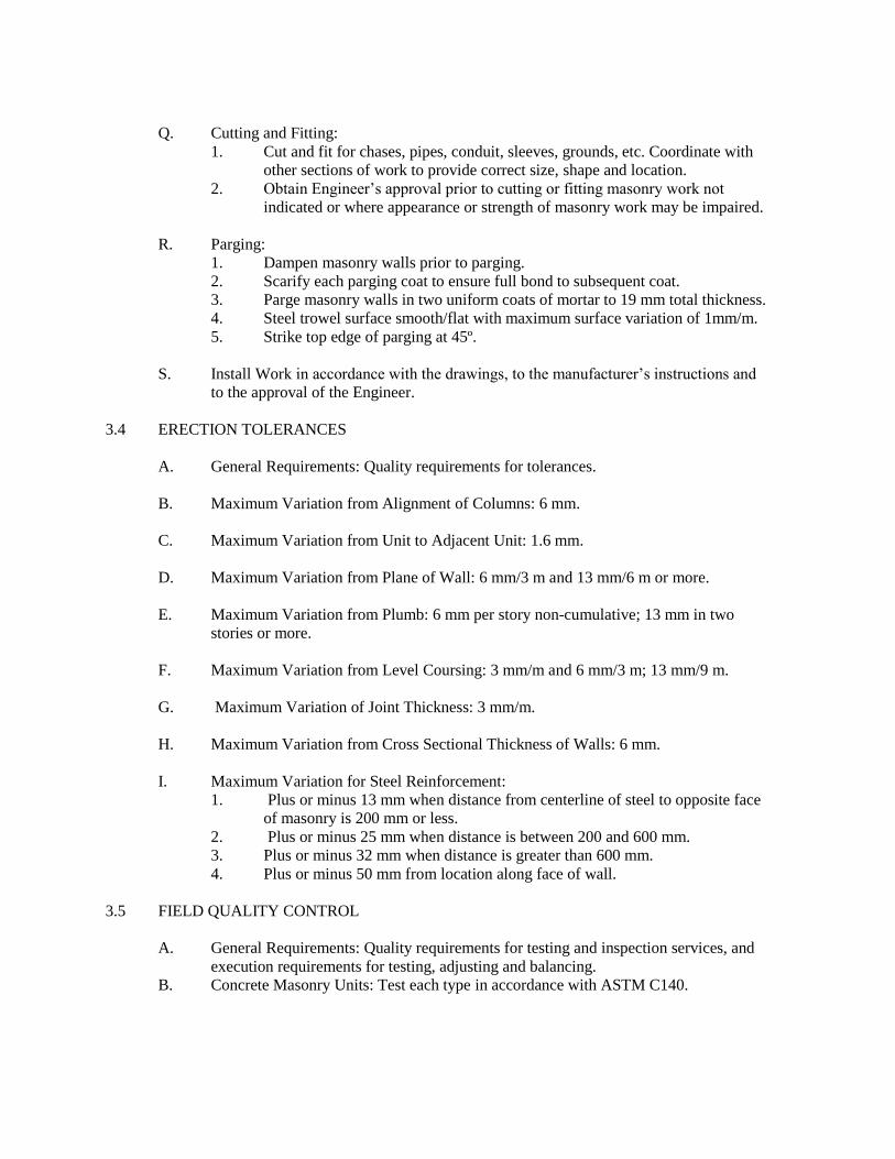
3.4 ERECTION TOLERANCES
A. General Requirements: Quality requirements for tolerances.
B. Maximum Variation from Alignment of Columns: 6 mm.
C. Maximum Variation from Unit to Adjacent Unit: 1.6 mm.
D. Maximum Variation from Plane of Wall: 6 mm/3 m and 13 mm/6 m or more.
E. Maximum Variation from Plumb: 6 mm per story non-cumulative; 13 mm in two
stories or more.
F. Maximum Variation from Level Coursing: 3 mm/m and 6 mm/3 m; 13 mm/9 m.
G. Maximum Variation of Joint Thickness: 3 mm/m.
H. Maximum Variation from Cross Sectional Thickness of Walls: 6 mm.
I. Maximum Variation for Steel Reinforcement:
1. Plus or minus 13 mm when distance from centerline of steel to opposite face
of masonry is 200 mm or less.
2. Plus or minus 25 mm when distance is between 200 and 600 mm.
3. Plus or minus 32 mm when distance is greater than 600 mm.
4. Plus or minus 50 mm from location along face of wall.
3.5 FIELD QUALITY CONTROL
A. General Requirements: Quality requirements for testing and inspection services, and
execution requirements for testing, adjusting and balancing.
B. Concrete Masonry Units: Test each type in accordance with ASTM C140.

3.6 CLEANING
A. General Requirements: Execution requirements for final cleaning.
B. Remove excess mortar and mortar smears as work progresses.
C. Replace defective mortar. Match adjacent work.
D. Clean soiled surfaces with cleaning solution.
E. Use non-metallic tools in cleaning operations.
3.7 SCHEDULES
As indicated on drawings and where directed by the Engineer.
END OF SECTION

SECTION 05120
STRUCTURAL STEEL
PART 1 GENERAL
1.1 SUMMARY
A. Section includes structural steel framing members, support members, suspension
cables, sag rods, and struts; base or bearing plates, shear stud connectors, and
expansion joint plates; anchor bolts for structural steel; beams, girders, purlins, and
girts; bearing of steel for girders, trusses or bridges; bracing; columns, posts;
connecting materials for framing structural steel to structural steel; crane rails,
splices, stops, bolts, and clamps; door frames constituting part of structural steel
frame; expansion joints connected to structural steel frame; fasteners for connecting
structural steel items; permanent shop bolts; shop bolts for shipment; field bolts for
permanent connections; permanent pins; floor plates (checkered or plain) attached to
structural steel frame; grillage beams and girders; hangers essential to structural steel
frame; leveling plates, wedges, shims, and leveling screws; lintels, when attached to
structural steel frame; trusses; and grouting under base plates.
B. Related Sections:
1. Section 04065 - Masonry Mortar and Grout.
2. Section 05500 - Metal Fabrications.
1.2 REFERENCES (Equivalent Equal Acceptable)
A. American Institute of Steel Construction:
1. AISC S303 - Code of Standard Practice for Steel Buildings and Bridges.
B. ASTM International:
1. ASTM A6/A6M - Standard Specification for General Requirements for
Rolled Structural Steel Bars, Plates, Shapes, and Sheet Piling.
2. ASTM A36/A36M - Standard Specification for Carbon Structural Steel.
3. ASTM A53/A53M - Standard Specification for Pipe, Steel, Black and Hot-
Dipped, Zinc-Coated, Welded and Seamless.
4. ASTM A123/A123M - Standard Specification for Zinc (Hot-Dip Galvanized)
Coatings on Iron and Steel Products.
5. ASTM A153/A153M - Standard Specification for Zinc Coating (Hot-Dip) on
Iron and Steel Hardware.
6. ASTM A242/A242M - Standard Specification for High-Strength Low-Alloy
Structural Steel.
7. ASTM A307 - Standard Specification for Carbon Steel Bolts and Studs, 60
000 PSI Tensile Strength.
8. ASTM A325M - Standard Specification for High-Strength Bolts for
Structural Steel Joints (Metric).
9. ASTM A449 - Standard Specification for Quenched and Tempered Steel
Bolts and Studs.
10. ASTM A490M - Standard Specification for High-Strength Steel Bolts,
Classes 10.9 and 10.9.3, for Structural Steel Joints (Metric).

11. ASTM A500 - Standard Specification for Cold-Formed Welded and
Seamless Carbon Steel Structural Tubing in Rounds and Shapes.
12. ASTM A501 - Standard Specification for Hot-Formed Welded and Seamless
Carbon Steel Structural Tubing.
13. ASTM A514/A514M - Standard Specification for High-Yield-Strength,
Quenched and Tempered Alloy Steel Plate, Suitable for Welding.
14. ASTM A529/A529M - Standard Specification for High-Strength Carbon-
Manganese Steel of Structural Quality.
15. ASTM A563M - Standard Specification for Carbon and Alloy Steel Nuts
(Metric).
16. ASTM A568/A568M - Standard Specification for Steel, Sheet, Carbon, and
High-Strength, Low-Alloy, Hot-Rolled and Cold-Rolled, General
Requirements for.
17. ASTM A572/A572M - Standard Specification for High-Strength Low-Alloy
Columbium-Vanadium Structural Steel.
18. ASTM A992 - Standard Specification for Steel for Structural Shapes.
C. American Welding Society:
1. AWS A2.4 - Standard Symbols for Welding, Brazing, and Nondestructive
Examination.
2. AWS D1.1 - Structural Welding Code - Steel.
D. Research Council on Structural Connections:
1. RCSC - Specification for Structural Joints Using ASTM A325 or A490 Bolts.
E. The Society for Protective Coatings (SSPC):
1. SSPC - Steel Structures Painting Manual.
2. SSPC Paint 15 - Steel Joist Shop Paint.
3. SSPC Paint 20 - Zinc-Rich Primers (Type I - Inorganic & Type II - Organic).
F. Underwriters Laboratories Inc.:
1. UL - Fire Resistance Directory.
1.3 SUBMITTALS
A. General Requirements: Requirements for submittals procedures.
B. Fabrication Drawings:
1. Indicate profiles, sizes, spacing, location of structural members, openings,
attachments and fasteners.
2. Design and details of connections.
3. Cambers and loads.
4. Indicate welded connections with AWS A2.4 symbols and net weld lengths.
C. Mill Test Reports: Submit indicating structural strength, and destructive and
nondestructive test analysis.
D. Manufacturer's Mill Certificate: Certify products meet the specified requirements.
E. Welders Certificates: Certify welders employed on the Work, verifying AWS
qualification within previous 12 months.

1.4 QUALITY ASSURANCE (Equivalent Equal Acceptable)
A. Fabricate structural steel members in accordance with AISC S303.
B. Perform Work in accordance with AISC S303, Section 10.
A. Maintain one copy of each document on site.
D. Fabricator: Company specializing in performing Work of this section with minimum
twenty years documented experience and holding current AISC Certification.
E. Erector: Company specializing in performing Work of this section with minimum ten
years documented experience.
1.5 DELIVERY, STORAGE AND HANDLING
A. Store materials to permit easy access for inspection and identification. Support steel
members off ground. Protect steel members and packaged materials from corrosion
and deterioration. Materials showing evidence of damage will be rejected and shall be
immediately removed from the site.
B. Do not store materials on structure in a manner that might cause distortion or damage
to members or supporting structures. Repair or replace damaged materials or
structures as directed.
C. Do not handle structural steelwork until paint has thoroughly dried. Care shall be
exercised to avoid abrasions and other damage.
D. All fasteners and washers shall be delivered to the site, where they will be installed,
in unopened containers.
PART 2 PRODUCTS
2.1 MATERIALS (Equivalent Equal Acceptable)
A. Manufacturer: Any internationally recognized manufacturer having an official
technical agreement to conformity with standards for the product.
B. Structural Steel Members: ASTM A36/A36M, ASTM A242/A242M, ASTM
A514/A514M, ASTM A529/A529M, ASTM A568/A568M, and/or ASTM
A572/A572M, Grade 40.
C. Structural Tubing: ASTM A500 and/or ASTM A501.
D. Pipe: ASTM A53/A53M, Grade B.
E. Shear Stud Connectors: ASTM A449. Forged steel, headed, and/or unfinished.
F. Suspension Cable: Wire rope.

G. Sag Rods: ASTM A36/A36M.
H. Bolts, Nuts, and Washers: ASTM A307, ASTM A325M bolts, ASTM A449 bolts,
ASTM A490M bolts, ASTM A563 nuts, and/or galvanized to ASTM A123/A123M
A153/A153M for galvanized structural members.
I. Anchor Bolts: ASTM A307 for embedded anchors; and high strength bolts for
chemically and mechanically anchored anchors.
J. Welding Materials: AWS D1.1; type required for materials being welded.
K. Sliding Bearing Plates: Teflon coated.
L. Grout: Non-shrink type, pre-mixed compound consisting of non-metallic aggregate,
cement, water reducing and plasticizing additives, capable of developing minimum
compressive strength of 48 MPa at 28 days.
M. Shop and Touch-Up Primer: SSPC 15, Type 1, red oxide.
N. Touch-Up Primer for Galvanized Surfaces: SSPC 20, Type I: Inorganic, or Type II:
Organic.
2.2 FABRICATION (As Below Unless Agreed Otherwise With Owner)
A. General:
1. Fabrication to be performed in accordance with Chapter M of AISC
“Specification for Structural Steel Buildings” and the Drawings and
Specifications.
a. Assume all thermally cut edges are subject to substantial stresses.
b. Paragraph M4.6 shall be considered deleted from Chapter M.
c. The last sentence of paragraph M5.1 shall be deleted.
2. Provide holes and accessories required for securing other work to the work
specified here.
3. Where thickness of material exceeds 7/8 inch or the diameter of hole, drill or
ream holes after punching even when punching is allowed by referenced
standards. Flame cut holes for fasteners are not acceptable.
4. Fabricate beams and girders with natural camber upward, unless otherwise
shown or indicated on the Drawings.
5. Splice members only where indicated on Structural Drawings or where
accepted by the Architect.
6. Remove burrs that would prevent solid seating of the connected parts.
B. Architecturally Exposed Steel:
1. All members exposed to view in the completed structure shall be classified as
“Architecturally Exposed Structural Steel”.
2. Comply with the provisions of the AISC Code of Standard Practice for Steel
Buildings and Bridges regarding architecturally exposed structural steel.
a. Abutting cross sectional configurations shall match.
b. Remove backing bars.
c. Remove weld runoff tabs and grind smooth

d. All surfaces and welds exposed to view shall be treated as finished
surfaces.
3. Exposed Welds:
a. All exposed fillet welds shall be made smooth of uniform convex
contour, radius and dimension for their full length; grind smooth, if
welds were not made to this criteria.
b. All other exposed welds shall be milled or ground smooth and flush
with the surfaces of the adjoining materials welded.
4. Weld show-through shall not be permitted.
5. Remove weld splatter on architecturally exposed steel.
6. All exposed corners shall be square and sharp, eased to a radius of 1/4 in.
C. Bolting, General:
1. Bolts shall be of a length that will extend not less than 1/4 in beyond the nuts
unless noted otherwise.
2. Washers shall be used on Bolts. Use beveled washers where bolts bear on
sloping surface.
3. Bolts shall be installed such that no threads occur in the shear plane.
4. Manufacturer’s symbol and grade markings shall appear on all bolts and nuts.
5. Product containers must be marked so that correspondence with mill reports
can be established.
6. Holes in column base-plates shall be no more than _ inch larger than the
nominal bolt size.
7. Circular and slotted holes shall be as per Specification for Structural Joints
Using ASTM A325 or A490 Bolts.
8. When bolt holes are subject to welding shrinkage stresses the holes shall be
drilled.
D. Unfinished Bolts and Anchor Bolts:
1. Install and tighten unfinished bolts in accordance with requirements for snug
tightened bolts as defined in “Specification for Structural Joints Using ASTM
A325 or A490 Bolts”.
2. Mutilate bolt threads for unfinished bolts to prevent the nuts from backing off.
E. High-Strength Bolts:
1. Install high-strength threaded fasteners in accordance with RCSC
“Specifications for Structural Joints using ASTM A 325 or A 490 Bolts”.
Contact surfaces of bolted parts shall as a minimum comply with the class A
requirements.
2. Unless otherwise noted, all connections are “slip critical (friction) type”.
3. Tighten nuts using Direct Tension Indicator. Calibrated wrench and “Turn of
Nut” methods are not acceptable.
4. When connection has bolts and welds, tighten bolts prior to welding with the
exception that in moment connections the flange welds are completed prior to
final tightening of high strength bolts.
5. When already tensioned bolts have had their tension relaxed, either re-torque
the bolts using a calibrated wrench or replace the bolt and/or tension indicator
and re-tighten.
F. Welding:
1. Welding shall be in accordance with AWS D1.1 “Structural Welding Code”.

a. Contractor is responsible for selection of specific materials and
procedures except as specifically noted in contract documents.
b. Connections have varying levels of restraint and thus necessary steps
shall be taken by Contractor to control or accommodate the restraint.
c. Welding and fabrication procedures shall incorporate measures
necessary to eliminate cracking. These measures shall include but are
not limited to additional preheat, postheat, or retarded cooling.
d. When selecting materials and procedures, consideration shall be
given to the need for materials and procedures in excess of code
requirements.
e. The need for pre-heat and other procedures are to be based on the
actual chemistry and mechanical properties and not solely on the
grade for which the steel was certified.
f. Weld variables shall be consistent with the recommendations of the
electrode manufacturer.
g. Welding Procedure Specifications shall be readily available to all
welders, inspectors, and supervisors.
h. Welding procedures shall incorporate low hydrogen practices.
i. Use stringer beads only (no weaving).
2. No tack welds not incorporated into a weld will be allowed on the finished
structure with the exception of backing plates that are not removed.
3. All groove or butt welds shall be full penetration unless noted otherwise on
the Drawings.
4. Do not weld into column flange to column web intersection.
5. Sequence the Work as necessary to accommodate testing.
6. Remove-run-off tabs and backup plates and grind surfaces smooth as required
for inspection or testing.
7. At “special moment connection” or “eccentrically braced frame” connections:
a. Remove backing bars and apply reinforcing fillet weld per note J of
figure 2.4 of AWS D1.1.
b. Remove weld runoff tabs and grind smooth.
c. Delete “…root and …” from subsection 4.14.1.5 of AWS D1.1-94
d. Limit oscillation of FCAW electrodes to 3d, for d > = 3/32 inches,
and to 5d, for d < 3/32 inch (d = wire diameter).
e. Pay increased attention to uniform and adequate preheat.
f. Maximum interpass temperature not to exceed 550 degrees F when
notch toughness properties are specified.
g. Complete individual weld layers prior to applying portions of
subsequent layers. Ends of interrupted passes to be staggered.
Minimize starts and stops within body of the weld.
8. Splices of members in tension, that are made from ASTM A6 Group 4 of 5
rolled shapes, and or plates more than 2 inches thick shall be made in
conformance with Section J1.7 of “Specification for Structural Steel
Buildings ASD”, 9th Edition.
9. Shear Studs: Install shear studs in accordance with the manufacturer’s
recommendations and AWS D1.1
10. Where tubes, pipes or other closed sections are exposed to the weather,
provide seal welds where other specified welds do not provide a complete
seal of the enclosed space.
G. Finishes of Architecturally Exposed Steel:

1. All surfaces of architecturally exposed structural steel members shall be
uniform in appearance, including smoothness and texture, when viewed in
direct sunlight at a distance of 10 feet, at angles of incidence 0 degree to 90
degree at completion of the following stages of work:
a. “Surface Preparation” and “Shop Prime Painting”.
2. Surface Appearance: The initial condition of steel to be exposed in use shall
conform to SSPC-V is 1 Rust Grade A. The exposed surfaces, edges and ends
of all plates and other components shall be free of any surface defects
including weld splatter, burrs, dents, gouges, occlusions, streak, ridges and
recesses. Such defects may be repaired and surface restored with weld or
other approved filler material and machining (milling, grinding or sanding) to
match appearance, including smoothness and texture, of parent surface.
3. All surfaces to be grit blasted to SA 2½ (Swedish Standards).
H. Shop Painting:
1. All structural steel exposed to the weather, classified as Architecturally
Exposed Steel, or not completely concealed by interior finishes shall receive
a shop coat of primer except as follows:
a. Steel in contact with concrete.
b. Contact surfaces of welded connections and areas within 4 in on each
side of field welds.
c. Machined surfaces.
d. Contact surfaces of high-strength bolted connections.
e. Reinforcing steel.
2. The following surfaces shall be temporarily protected by a thin coating of
varnish or lacquer:
a. Unpainted areas around field welds.
b. Steel around high strength bolts.
c. Machined surfaces.
2.3 FINISH (As Below Unless Agreed Otherwise With Owner)
A. Finish of Painted Steel Surfaces:
1. Prepare structural component surfaces in accordance with SSPC.
2. Grit blast surfaces to SA 2½ (Swedish Standards).
3. Shop prime structural steel members. Do not prime surfaces that will be
fireproofed, field welded, in contact with concrete or high strength bolted.
4. Apply an approved three-coat protective paint system; provide minimum ten
(10) year maintenance free guarantee for the paint system.
B. Finish of Galvanized Steel Surfaces:
1. Prepare structural component surfaces in accordance with SSPC.
2. Galvanize structural steel members to ASTM A123/A123M. Furnish
minimum 380g/m² galvanized coating.
3. Apply an approved mordant coat prior to receiving the protective paint system.
4. Apply an approved three-coat protective paint system; provide minimum ten
(10) year maintenance free guarantee for the paint system.

2.4 SOURCE QUALITY CONTROL AND TESTS (As Below Unless Agreed Otherwise With
Owner)
A. Testing and inspection of structural steelwork will be performed by the independent
testing agency cost of which shall be borne by Contractor. Provide the Inspector with
the following.
1. A complete set of accepted “Submittals”
2. Cutting lists, order sheets, material bills, and shipping bills
3. Representative sample pieces as requested by the testing agency
4. full and ample means and assistance for testing all material
5. Access and facilities, including scaffolding, temporary work platforms, etc.,
for testing and inspection at all places where materials or components are
stored or fabricated, and also in their erected position.
B. Scheduling of Tests and Inspections
1. The Contractor shall notify the Inspector in sufficient time prior to fabrication
or erection work to allow testing and inspection without delaying the work.
2. Shop welds will be inspected in the shop before the work is painted or
shipped.
C. Each person installing connections shall be assigned an identifying symbol or mark
and all shop and field connections shall be so identified so that the Inspector can refer
back to the person making the connection.
D. Non-destructive Testing and Inspections
1. As a minimum the inspector shall make all tests and inspections as required
by the 1997 Uniform Building Code Inspector will make all the tests and
inspections indicated in the Construction Documents.
2. The Inspector shall make all verification tests and inspections as required by
AWS D1.1 “Structural Welding Code”.
3. Do not reduce testing frequency unless permission is obtained from the
Engineer.
4. Inspector shall be present during all welding operations.
5. Verify that welders are certified.
6. Check materials, equipment and procedures. Verify meters on welding
equipment are functioning and are accurate.
7. Visual Inspection:
a. Visually inspect all welds.
b. Visual inspection of multi-pass welds to be continuous.
c. Visually inspect welds to Group 4 and 5 sections of at least 72 hours
after completion of welding for the presence of cracks.
8. Test Methods:
a. Butt welds will be tested using ultrasonic or radiographic test
methods.
b. Butt welds to pipes and tubes to be tested using magnetic particle tests.
c. Use magnetic partial test methods for filet welds and the supplement
the testing requirements for butt welds.
d. At inspector’s option dye penetrant testing, and resistance testing
methods may be used in place of or to supplement magnetic particle
testing.

e. For radiographic a double film technique will be used. One copy of
each film will be sent to the Architect, the other will be retained by
the Inspector.
f. In addition to the non-destructive testing specified other nondestructive
test methods recognized by AWS D1.1 may be used at the
Architects discretion and the results can be used to reject work under
this contract.
9. Frequency of non-destructive examination is to be as follows:
a. Full penetration butt welds: 100 percent.
b. Partial penetration butt welds with a leg length greater than 1/2 in: 20
percent min. ultrasonic or radiographic inspection.
c. Test 100 % of partial penetration butt welds used in column splices.
d. Test 20 % of total length of all welds joining web plates to flanges.
e. Fillet and other welds not otherwise addressed - a minimum of 10 %.
f. Selection of welds to be examined: Where there is a requirement for
less than 100% examination the method of selection of welds to be
examined is to be agreed with the Engineer before commencement of
the work. If the Engineer does not provide more specific criteria
inspectors will select the welds to be tested. The inspectors will chose
specific weld so as to obtain results that are representative of the
conditions in the structure. In addition inspectors will emphasize
those locations that experience has shown are more likely to have
problems.
g. On five percent of the full penetration butt welds as chosen by the
inspector/engineer, after removing, run-off tabs, grind the end of the
weld sufficiently to allow determination of number and sizes of weld
passes.
10. Testing of Base Metal: These provisions are in addition to other applicable
requirements.
a. The edges of material to be welded will be ultrasonically examined
for evidence of laminations, inclusions or other discontinuities.
b. Ultrasonically test column flanges and webs at the location of all
moment connections and brace connections. Test for a distance 3
inches around the location to be welded. The test procedure and
acceptance criteria is defined by ASTM A898-91, “Standard
Specification for Straight Beam Ultrasonic Examination of Rolled
Steel Structural Shapes” Level I.
c. Base metal thicker than 1½ inches, when subjected to throughthickness
weld shrinkage strains, shall be ultrasonically inspected for
discontinuities behind and within a distance of 3 inches of such welds
after joint completion. Any material discontinuities shall be accepted
or rejected on the basis of the defect rating in accordance with flaw
severity, Class B criteria in Table 8.2 in AWS D1.1.
11. Where inspection reveals unacceptable defects:
a. The extent of inspection will be increased as much as necessary to
assure that the full extent of the defects in a joint has been found and
to assure that the same defects are not present elsewhere.
b. As minimum, examine two additional joints in the group represented
by the joint. If the non-destructive examination of the two additional
joints reveals unacceptable defects, examine each joint in the group.

E. Take samples of all welding consumables and store in sealed containers.
F. Tests of high strength bolts, nuts and washers:
1. The Inspector will make all tests and inspections of high strength bolt
connections as required by RCSC “Specifications for Structural Joints Using
ASTM A 325 or A 490 Bolts”.
2. Observe all Direct Tension Indicators to see if proper tightness was achieved.
3. Confirm that the faying surfaces have been properly prepared before
connections are assembled.
G. Testing of End-Welded Studs:
1. End-welded studs shall be random sampled and tested from stock furnished
to each project. Tests shall meet the requirements in Table 7.1 of AWS D1.1.
The minimum number of tests of each required property shall be as follows:
Number of Pieces to Be Used
from Identified Package
Number of Specimens
150 and less 1
151 to 280 2
281 to 500 3
501 to 1200 5
1201 to 3200 8
3201 to 10000 13
10001 and over 20
A minimum of three pieces from each lot shall be tested.
2. Production control testing shall be in accordance with AWS D1.1 Chapter 7.
3. As a minimum test, in accordance with AWS D1.1 paragraph 7.8, ten percent
of all welded studs.
H. Inspection Records
1. Make systematic record of all welds, including:
a. Location and type of weld.
b. Identification marks of welders.
c. List of defective welds.
d. Manner of correction of defects.
2. The Inspector will maintain a daily record of the work that has been inspected
and its disposition. One copy of each of the report will be submitted to the
Owner on a weekly basis. Test reports will be made on the form suggested in
the AWS D1.1 “Structural Welding Code”.
PART 3 EXECUTION
3.1 EXAMINATION
A. General Requirements: Administrative requirements for coordination and project
conditions.
3.2 ERECTION
A. Allow for erection loads, and for sufficient temporary bracing to maintain structure

safe, plumb, and in alignment until completion of erection and installation of
permanent bracing.
B. Field weld components and shear studs as indicated on fabrication drawings.
C. Field connect members with threaded fasteners; torque to required resistance tighten
to snug tight for bearing type connections.
D. Do not field cut or alter structural members without approval of the Engineer.
E. After erection, prime welds, abrasions and surfaces not shop primed or galvanized,
except surfaces to be in contact with concrete.
F. Grout under base plates in accordance with Section 04065. Trowel grouted surface
smooth, splay neatly to 45 degrees.
3.3 ERECTION TOLERANCES
A. General Requirements: Quality requirements for tolerances.
B. Maximum Variation from Plumb: 6 mm per story, non-cumulative.
C. Maximum Offset from Alignment: 6 mm.
3.4 FIELD QUALITY CONTROL
A. General Requirements: Quality requirements for testing and inspection services, and
execution requirements for testing, adjusting and balancing.
3.5 SCHEDULES
A. As indicated on drawings and where directed by the Engineer.
END OF SECTION

SECTION 05500
METAL FABRICATIONS
PART 1 GENERAL
1.1 SUMMARY
A. Section includes shop fabricated metal items.
B. Related Sections:
1. Section 03300 - Cast-In-Place Concrete.
2. Section 04810 - Unit Masonry Assemblies.
3. Section 05510 - Metal Stairs and Ladders.
4. Section 05520 - Handrails and Railings.
5. Section 07140 - Fluid Applied Waterproofing.
6. Section 07212 - Board Insulation.
7. Section 07260 - Vapor Retarders.
8. Section 07270 - Air Barriers.
9. Section 07900 - Joint Sealers.
10. Section 09900 - Paints and Coatings.
11. Division 15 - Mechanical: Diffusers, registers and grilles.
1.2 REFERENCES
A. Aluminum Association:
1. AA DAF-45 - Designation System for Aluminum Finishes.
B. American Architectural Manufacturers Association:
1. AAMA 611 - Voluntary Specification for Anodized Architectural Aluminum.
2. AAMA 2603 - Voluntary Specification, Performance Requirements and Test
Procedures for Pigmented Organic Coatings on Aluminum Extrusions and
Panels.
3. AAMA 2604 - Voluntary specification, Performance Requirements and Test
Procedures for High Performance Organic Coatings on Aluminum Extrusions
and Panels.
4. AAMA 2605 - Voluntary Specification, Performance Requirements and Test
Procedures for Superior Performing Organic Coatings on Aluminum
Extrusions and Panels.
C. ASTM International:
1. ASTM A36/A36M - Standard Specification for Carbon Structural Steel.
2. ASTM A53/A53M - Standard Specification for Pipe, Steel, Black and Hot-
Dipped, Zinc-Coated, Welded and Seamless.
3. ASTM A123/A123M - Standard Specification for Zinc (Hot-Dip Galvanized)
Coatings on Iron and Steel Products.
4. ASTM A153/A153M - Standard Specification for Zinc Coating (Hot-Dip) on
Iron and Steel Hardware.
5. ASTM A167 - Standard Specification for Stainless and Heat-Resisting
Chromium-Nickel Steel Plate, Sheet, and Strip.

6. ASTM A276 - Standard Specification for Stainless Steel Bars and Shapes.
7. ASTM A297/A297M - Standard Specification for Steel Castings, Iron-
Chromium and Iron-Chromium-Nickel, Heat Resistant, for General
Application.
8. ASTM A283/283M - Standard Specification for Low and Intermediate
Tensile Strength Carbon Steel Plates.
9. ASTM A307 - Standard Specification for Carbon Steel Bolts and Studs,
60000 PSI Tensile Strength.
10. ASTM A312/A312M - Standard Specification for Seamless and Welded
Austenitic Stainless Steel Pipes.
11. ASTM A325M - Standard Specification for High-Strength Bolts for
Structural Steel Joints (Metric).
12. ASTM A354 - Standard Specification for Quenched and Tempered Alloy
Steel Bolts, Studs, and Other Externally Threaded Fasteners.
13. ASTM A500 - Standard Specification for Cold-Formed Welded and
Seamless Carbon Steel Structural Tubing in Rounds and Shapes.
14. ASTM A501 - Standard Specification for Hot-Formed Welded and Seamless
Carbon Steel Structural Tubing.
15. ASTM A554 - Standard Specification for Welded Stainless Steel Mechanical
Tubing.
16. ASTM B26/B26M - Standard Specification for Aluminum-Alloy Sand
Castings.
17. ASTM B85 - Standard Specification for Aluminum-Alloy Die Castings.
18. ASTM B177 - Standard Guide for Chromium Electroplating on Steel for
Engineering Use.
19. ASTM B209M - Standard Specification for Aluminum and Aluminum-Alloy
Sheet and Plate (Metric).
20. ASTM B210M - Standard Specification for Aluminum and Aluminum-Alloy
Drawn Seamless Tubes (Metric).
21. ASTM B211M - Standard Specification for Aluminum and Aluminum-Alloy
Bar, Rod, and Wire (Metric).
22. ASTM B221M - Standard Specification for Aluminum and Aluminum-Alloy
Extruded Bars, Rods, Wire, Profiles, and Tubes (Metric).
D. American Welding Society:
1. AWS A2.4 - Standard Symbols for Welding, Brazing, and Nondestructive
Examination.
2. AWS D1.1 - Structural Welding Code - Steel.
3. AWS D1.6 - Structural Welding Code - Stainless Steel.
E. National Ornamental & Miscellaneous Metals Association:
1. NOMMA Guideline 1 - Joint Finishes.
F. The Society for Protective Coatings (SSPC):
1. SSPC - Steel Structures Painting Manual.
2. SSPC SP 1 - Solvent Cleaning.
3. SSPC SP 2 - Hand Tool Cleaning.
4. SSPC SP 10 - Near-White Blast Cleaning.
5. SSPC Paint 15 - Steel Joist Shop Paint.
6. SSPC Paint 20 - Zinc-Rich Primers (Type I - Inorganic & Type II - Organic).

1.3 SUBMITTALS
A. General Requirements: Requirements for submittal procedures.
B. Shop Drawings: Indicate profiles, sizes, connection attachments, reinforcing,
anchorage, size and type of fasteners, and accessories. Include erection drawings,
elevations, and details where applicable. Indicate welded connections using standard
AWS A2.0 welding symbols. Indicate net weld lengths.
C. Shop Drawings for Slab edge Panels: Indicate dimensions, panel profile and layout,
spans, joints, expansion joints, construction details, methods of anchorage, method
and sequence of installation and interface with adjacent materials.
D. Samples: Submit two samples of each metalwork type, size as directed by the
Engineer, illustrating factory finishes.
E. Welders Certificates: Certify welders employed on the Work, verifying AWS
qualification within previous 12 months.
F. Design and Performance Data: Submit panel profile characteristics and dimensions,
and structural properties. Submit design calculations.
G. Manufacturer's Installation Instructions: Submit special handling criteria, installation
sequence, and cleaning procedures.
1.4 QUALITY ASSURANCE
A. Materials and work shall conform to the latest edition of reference specified herein
and to applicable codes and requirements of local authorities having jurisdiction,
including the following:
1. The National Association of Architectural Metal Manufacturers (NAAMM)
a. Metal Finishes Manual
b. Metal Bar Grating Manual
c. Metal Products Outline Manual
B. Qualify welding processes and welding operators in accordance with AWS D1.1
“Structural Welding Code – Steel,” D1.3 “Structural Welding Code – Sheet Steel”,
and D1.2 “Structural Welding Code – Aluminum”.
C. Structural Performance: Design, engineer, fabricate and install metal fabrications to
withstand structural loads without exceeding the allowable design working stress of
the materials involved, including anchors and connections. Comply with the
“Performance Criteria” specified hereinafter.
D. Conflicting Requirements: In the event of conflict between pertinent codes and
regulations and the requirements of the referenced standards or these specifications,
the provisions of the more stringent shall govern.
E. Design cold-formed framing to comply with ASCE-7-95 and Uniform Building Code.
1. Design Load for Exterior Wall assembly: Not less than 146 kg/m².

2. Increase size of individual members, including anchorage, or reinforce to
resist loads without undue deflection.
F. Maximum Horizontal Deflection at Mid-Plan
1. At Ceramic Tile: 10mm or L/600 of span based on moment of inertia of stud
cross section only, whichever is less.
2. Increase size of individual members, including anchorage, or reinforce to
resist loads without undue deflection.
G. Sloped Sills: Size to resist wind loads plus anticipated live loads of 195 kg/m², but not
less than 1.5mm thick.
H. Interior Locations Indicated as Structural Steel Stud: Size to resist anticipated loads,
but not less than 0.9mm thick unless otherwise indicated.
I. Differential Movement: Design and construct wall system to accommodate
anticipated movement indicated herein, without damage or deterioration to studs or
wallboards, without buckling, opening of joints, and cracking.
J. Certifications: Work of this Section shall be performed under the direct supervision of
a registered Professional Engineer.
K. Perform Work in accordance with the drawings and to the approval of the Engineer.
L. Maintain one copy of each document on site.
1.5 QUALIFICATIONS
A. Design under direct supervision of Professional Engineer experienced in design of
this Work and approved by the Engineer.
B. Manufacturer: Company specializing in manufacturing products specified in this
section with minimum ten years documented experience.
C. Installer: Company specializing in performing Work of this section with minimum
five years documented experience.
1.6 DELIVERY, STORAGE AND HANDLING
A. General Requirements: Product requirements for product storage and handling.
B. Accept metal fabrications on site in labeled shipments. Inspect for damage.
C. Protect metal fabrications from damage by exposure to weather.
1.7 FIELD MEASUREMENTS
A. Verify field measurements are as indicated on shop drawings, and/or as instructed by
the manufacturer.

PART 2 PRODUCTS
2.1 MATERIALS - STEEL
A. Steel Sections: ASTM A36/A36M.
B. Steel Tubing: ASTM A500, Grade B, and/or ASTM A501.
C. Plates: ASTM A283/A283M.
D. Pipe: ASTM A53/A53M, Grade B, Schedule 40.
E. Fasteners: as instructed by the manufacturer.
F. Bolts, Nuts, and Washers: ASTM A325M, A307 and/or galvanized to ASTM
A153/A153M for galvanized components.
G. Welding Materials: AWS D1.1; type required for materials being welded.
H. Shop and Touch-Up Primer: SSPC Paint 15, Type 1, red oxide.
I. Touch-Up Primer for Galvanized Surfaces: SSPC Paint 20 Type I Inorganic and/or
Type II Organic zinc rich.
2.2 MATERIALS - STAINLESS STEEL
A. Bars and Shapes: ASTM A276, and/or ASTM A479/A479M; Type 316.
B. Tubing: ASTM A269, and/or ASTM A554; Type 316.
C. Pipe: ASTM A312/A312M, seamless and/or welded; Type 316.
B. Plate, Sheet and Strip: ASTM A167; Type 316.
E. Bolts, Nuts, and Washers: ASTM A354.
F. Welding Materials: AWS D1.6; type required for materials being welded.
2.3 MATERIALS - ALUMINUM
A. Extruded Aluminum: ASTM B221M, Alloy 6063, Temper T5.
B. Sheet Aluminum: ASTM B209M.
C. Aluminum-Alloy Drawn Seamless Tubes: ASTM B210M, Alloy 6063, Temper T6.
D. Aluminum-Alloy Bars: ASTM B211M, Alloy 6063, Temper T6.
E. Aluminum-Alloy Sand Castings: ASTM B26/B26M.

F. Aluminum-Alloy Die Castings: ASTM B85.
G. Bolts, Nuts, and Washers: Stainless steel type 316.
H. Welding Materials: AWS D1.1; type required for materials being welded.
2.4 ISOLATING NON-CONDUCTIVE MATERIALS BETWEEN DISSIMILAR METALS
A. Contacts between dissimilar metals should be avoided in order to prevent bi-metallic
or galvanic corrosion.
B. Dissimilar metals shall be isolated from each other with non-conductive materials.
Generally, such isolating elements will take the form of washers and bushes.
C. Isolated Non-Conductive Materials: Neoprene, synthetic resin bonded fiber (SRBF)
such as tufnol, polytetrafluoroethylene (PTFE), or hard nylon, depending on the fixing:
1. Load Bearing Fixings: SRBF or PTFE (strong material).
2. Restraint Fixings: Neoprene or nylon is acceptable.
D. Electrical insulation tape and bitumen paint are considered in low risk short life
application, and shall not be used as non-conductive materials unless directed by the
Engineer.
2.5 LINTELS
A. Lintels: Steel sections, size and configuration as indicated on Drawings, length to
allow 200 mm minimum bearing on both sides of opening.
1. Exterior Locations: Galvanized, and/or prime paint, one coat.
2. Interior Locations: Prime paint, one coat.
2.6 LEDGE AND SHELF ANGLES
A. Ledge and Shelf Angles, Channels and/or Plates Not Attached to Structural Framing: For
support of metal decking, joists, and/or masonry; galvanized and/or prime paint, one coat.
2.7 ELEVATOR SILL ANGLES AND HOIST AND DIVIDER BEAMS
A. Sill Angles: Steel sections as indicated on Drawings for support of elevator sills;
galvanized and/or prime paint, one coat.
B. Hoist and Divider Beams: Steel wide flange sections, shape and size required to support
applied loads with maximum deflection of 1/240 of the span; prime paint, one coat.
2.8 DOOR FRAMES
A. Door Frames: Steel channel and/or angle sections, size as indicated on Drawings,
with jamb anchors suitable for building into masonry and/or attachment to concrete,
or steel framing, minimum 4 anchors per jamb; galvanized or prime paint, one coat.

2.9 LADDERS
A. Steel, Aluminum and/or Stainless Steel Ladder: ANSI A14.3, steel, aluminum and/or
stainless steel welded construction: Unless otherwise indicated on drawings,
1. Side Rails: 9 x 50 mm side rails spaced at 500 mm.
2. Rungs: 25 mm diameter solid and/or tubular rod spaced 300 mm on center.
3. Mounting: Space rungs 175 mm from wall surface; with steel mounting
brackets and attachments.
4. Finish: Galvanized, enamel, anodized, satin chrome, or polished chrome
finish, as selected.
B. Ladder Safety Cage: Unless otherwise indicated on drawings, Steel and/or Aluminum
bar sections, minimum 6 x 50 mm.
1. Bottom hoop 455 mm radius maximum 1880 mm above finished floor.
2. Other hoops 355 mm radius spaced maximum 1220 mm on center.
3. Vertical bars spaced 250 mm on center.
4. Finish: Match ladder finish.
C. Ladder Security Enclosure: Unless otherwise indicated on drawings, Sheet steel
minimum 1.5 mm thick, formed to enclose ladder side rails and rungs when closed
and to swing free of ladder rungs and side rails with minimum 38 mm clear to side
rails in open position.
1. Provide continuous steel hinge full height of enclosure.
2. Provide steel hasp for padlocking in closed and open position.
3. Finish: Match ladder finish.
2.10 STRUCTURAL SUPPORTS
A. Structural Supports for Miscellaneous Attachments: Steel sections, shape and size as
indicated on Drawings, required to support applied loads (Dead & Live) with
maximum deflection of 1/200 of the span; prime paint, one coat or mill finish.
2.11 ALUMINUM VENTILATION GRILL LOUVERS
A. Coordinate Work with Division 15 - Mechanical and in particular Diffusers,
Registers, and Grilles.
2.12 ANCHOR BOLTS
A. Anchor Bolts: ASTM A307; steel bolt, standard J-hook, with nut and washer;
unfinished.
2.13 FOOT SCRAPERS
A. Foot Scrapers: As detailed; aluminum, mill finish and/or steel galvanized, or prime
paint, one coat.
2.14 FABRICATION
A. Fit and shop assemble items in largest practical sections, for delivery to site.

B. Fabricate items with joints tightly fitted and secured.
C. Continuously seal joined members by intermittent welds and plastic filler and/or
continuous welds.
D. Exposed Welded Joints: NOMMA Guideline 1 Joint Finish.
E. Exposed Mechanical Fastenings: Flush countersunk screws or bolts; unobtrusively
located; consistent with component design, except where specially noted otherwise.
F. Supply components required for anchorage of fabrications. Fabricate anchors and
related components of same material and finish as fabrication, except where
specifically noted otherwise.
2.15 FACTORY APPLIED FINISHES - STEEL
A. Prepare surfaces to be primed in accordance with SSPC SP 2.
B. Clean surfaces of rust, scale, grease, and foreign matter prior to finishing.
C. Do not prime surfaces in contact with concrete or where field welding is required.
D. Prime paint items with one or two coats except where galvanizing is specified.
E. Galvanized Structural Steel Members: Galvanize after fabrication to ASTM A123.
Furnish minimum 380 g/sq m galvanized coating.
F. Galvanized Non-structural Items: Galvanized after fabrication to ASTM A123.
Furnish minimum 380 and/or 360 g/m² galvanized coating.
G. Chrome Plating: ASTM B177, nickel-chromium alloy, satin and/or polished finish.
2.16 FACTORY APPLIED FINISHES - STAINLESS STEEL
A. Satin Polished Finish: Number 4, satin directional polish parallel with long dimension
of finished face. Color: As selected.
B. Mirror Polished Finish: Number 8, mirror polish with preliminary directional polish
lines removed. Color: As selected.
2.17 FACTORY APPLIED FINISHES - ALUMINUM
A. Finish coatings to conform to AAMA 2603, 2604, 2605 and/or AAMA 611. Comply
with AA DAF-45.
B. Exterior and Interior Aluminum Surfaces: Advanced Durability Polyester Powder
Coating System. Color: As selected. Minimum cover thickness 60 microns. Gloss
Percentage: As selected.
C. Apply one coat of bituminous paint to concealed aluminum surfaces in contact with

cementitious or dissimilar materials.
2.18 FABRICATION TOLERANCES
A. Squareness: 3 mm maximum difference in diagonal measurements.
B. Maximum Offset between Faces: 1.5 mm.
C. Maximum Misalignment of Adjacent Members: 1.5 mm.
D. Maximum Bow: 3 mm in 1.2 m.
E. Maximum Deviation from Plane: 1.5 mm in 1.2 m.
PART 3 EXECUTION
3.1 EXAMINATION
A. General Requirements: Administrative requirements for coordination and project
conditions.
B. Verify field conditions are acceptable and are ready to receive Work.
3.2 PREPARATION
A. Clean and strip primed steel items to bare metal and aluminum where site welding is
required.
B. Supply steel items required to be cast into concrete, or embedded in masonry with
setting templates to appropriate sections.
3.3 INSTALLATION
A. Install work of this section square, plumb, straight, true to line or radius, accurately
fitted and located, with flush tight hairline joints (except as indicated otherwise or to
allow for thermal movement). Provide attachment devices as required for secure and
rigid installation.
B. Exposed joints shall be close fitting, and bolts and screws, where exposed, shall be
cut off flush with nuts or other adjacent metal. Cutting, drilling, punching and tapping
required for the installation and attachment of other work to miscellaneous metal
work, except where specified in connection with work under other sections, shall be
performed as required.
C. Metal work built-in with concrete or masonry shall be formed for anchorage, or be
provided with suitable anchors, expansion shields or other anchoring devices shown
on the drawings, or required. Such metal work shall be furnished in ample time for
setting and securing in place. Wherever possible fixings shall be built into concrete.
D. Where indicated, install miscellaneous metal items in sleeves (furnished under this
section) embedded in concrete with setting grout specified herein.

E. Joints shall be as strong and rigid as adjoining sections. Welding shall be continuous
along entire line of contact, except where spot welding is indicated or permitted.
Where exposed, welds shall be ground smooth. Where bolted or riveted connections
are indicated, such connections may be welded at the Contractor’s option.
F. Where welding is required, it shall conform to requirements for shielded metal arc
welding of the Standard Code for Arc and Gas Welding of the American Welding
Society. Exposed welds shall be flush and ground smooth.
G. Threaded connections shall be made up tight so that threads are entirely concealed.
Abutting bars shall be so shouldered and headed, doweled and pinned. Small bars
shall pass through larger bars and pinned. Rivet, bolts and screw heads shall be flat
and countersunk in exposed work and elsewhere as required. Removable members
shall be carefully machined and fitted and secured, by means of screws or bolts of
proper size and approved spacing.
H. Bolts, brackets, sleeves and other items embedded in concrete shall be galvanized.
I. Except where built in fixings cannot be used miscellaneous metal work may be
fastened to concrete with expansion bolts and to hollow with toggle bolts. Fastening
to wood plugs in concrete or masonry will not be permitted. Holes for plugs or bolts
shall be drilled to the exact diameter of the plug or bolt, using a percussion drill for
concrete and a rotary drill for masonry. Screws shall be threaded full length to the
head of the screw.
J. Provide for adjustments of miscellaneous metal items, with particular attention given
to miscellaneous steel supporting the work of other sections, as required during the
construction process.
K. Install isolating non-conductive materials between dissimilar metals as per approved
methodology.
L. Setting Loose Plates:
1. Clean concrete and masonry bearing surfaces of any bond-reducing materials,
roughen to improve bond to surfaces. Clean bottom surface of bearing plates.
2. Set loose leveling and bearing plates on wedges, or other adjustable devices.
After the bearing members have been positioned and plumbed, tighten the
anchor bolts. Do not remove wedges or shims, but if protruding, cut off flush
with the edge of the bearing plate before packing with grout.
3. Pack grout solidly between bearing surfaces and plates to ensure that no voids
remain.
M. Butt welds or splice butt joints in track. Splices in axial loaded studs shall not be
permitted. Welds shall be fillet, plug, butt, or seam.
1. Secure floor and ceiling runners to structure with power driven anchors
spaced not over 400mm on center and 150mm maximum from ends. Closer
spacing at discretion of stud manufacturer based on design loads.
2. Provide elastomeric sealant or sill sealer material between concrete structure
and ceiling and floor runner channels at exterior.

N. Slide Clip Detail: Provide flexible connection between studs and building structure to
accommodate slab edge deflection and long term building creep without transferring
axial load to studs.
O. Tolerance: Wall construction to a maximum variation from plumb, level, or true-toline
of 3mm in 3m.
P. Obtain approval of the Engineer prior to site cutting or making adjustments not
scheduled.
Q. After erection, touch up welds, abrasions, and damaged finishes with prime paint or
galvanizing repair paint to match shop finishes.
3.4 ERECTION TOLERANCES
A. General Requirements: Quality requirements for tolerances.
B. Maximum Variation from Plumb: 6 mm per story or for every 3.65 m in height
whichever is greater, non-cumulative.
C. Maximum Offset from Alignment: 6 mm.
D. Maximum Out-of-Position: 6 mm.
3.5 CLEANING
A. General Requirements: Execution requirements for final cleaning.
B. Remove site cuttings from finish surfaces.
C. Clean and wash prefinished surfaces with mild soap and water; rinse with clean
water.
3.6 SCHEDULES
A. As indicated on drawings and where directed by the Engineer.
END OF SECTION

SECTION 06200
FINISH CARPENTRY
PART 1 GENERAL
1.1 SUMMARY
A. Section includes finish carpentry items; wood door frames, glazed frames; wood
casings and moldings; and hardware and attachment accessories.
B. Related Sections:
1. Section 06410 - Custom Cabinets: Shop fabricated custom cabinet work.
2. Section 08212 - Flush Wood Doors.
3. Section 08800 - Glazing.
4. Section 09900 - Paints and Coatings: Finishing of finish carpentry items.
1.2 REFERENCES
A. American National Standards Institute:
1. ANSI A135.4 - Basic Hardboard.
2. ANSI A156.9 - Cabinet Hardware.
3. ANSI A208.1 - Mat-Formed Wood Particleboard.
B. APA-The Engineered Wood Association:
1. APA/EWA PS 1 - Voluntary Product Standard for Construction and
Industrial Plywood.
C. ASTM International:
1. ASTM C1036 - Standard Specification for Flat Glass.
2. ASTM C1048 - Standard Specification for Heat-Treated Flat Glass-Kind HS,
Kind FT Coated and Uncoated Glass.
3. ASTM E84 - Standard Test Method for Surface Burning Characteristics of
Building Materials.
D. Architectural Woodwork Institute:
1. AWI - Quality Standards Illustrated.
E. American Wood-Preservers’ Association:
1. AWPA C1 - All Timber Products - Preservative Treatment by Pressure
Process.
F. Federal Specification Unit:
1. FS A-A-1936 - Adhesive, Contact, Neoprene Rubber.
G. Hardwood Plywood and Veneer Association:
1. HPVA HP-1 - American National Standard for Hardwood and Decorative
Plywood.
H. National Institute of Standards and Technology:
1. NIST PS 20 - American Softwood Lumber Standard.

I. National Electrical Manufacturers Association:
1. NEMA LD 3 - High Pressure Decorative Laminates.
J. Window and Door Manufacturers Association:
1. WDMA I.S.4 - Water-Repellent Treatment for Millwork.
K. Woodwork Institute of California:
1. WIC - Manual of Millwork.
1.3 SUBMITTALS
A. General Requirements: Requirements for submittal procedures.
B. Shop Drawings: Indicate materials, component profiles, fastening methods, jointing
details, and accessories to minimum scale of (1:8).
C. Product Data:
1. Submit data on fire retardant treatment materials and application instructions.
2. Submit data on attachment hardware and/or finish hardware.
D. Samples:
1. Submit two samples of finish plywood, 200 x 250 mm in size illustrating
wood grain and specified finish.
2. Submit two samples of wood trim 250 mm long.
3. Submit two samples of laminates, pre-finished paneling, synthetic surfacing,
hardware items, and/or shop finishes.
E. Certification: Submit copy of fabricator’s authorization to use AWI Grade Stamps,
AWI Quality Certification Program license and Project specific letters and/or WIC
certified compliance certificate.
1.4 QUALITY ASSURANCE
A. Perform work in accordance with AWI (Architectural Woodwork Institute)
Architectural Woodwork Quality Standards Illustrated, or WIC (Woodwork Institute
of California) Manual of Millwork; economy, custom or premium grade.
B. Maintain one copy of each document on site.
1.5 QUALIFICATIONS
A. Fabricator: Company specializing in fabricating Products specified in this section
with minimum ten years documented experience.
1.6 MOCKUP
A. General Requirements: Quality requirements for mockup.
B. Construct mockups, full size including all hardware and attachment accessories.

C. Locate where directed by the Engineer.
D. Remove mockup when directed by the Engineer.
1.7 PRE-INSTALLATION MEETINGS
A. General Requirements: Administrative requirements for pre-installation meeting.
B. Convene minimum one week prior to commencing work of this section.
1.8 DELIVERY, STORAGE AND HANDLING
A. General Requirements: Product requirements for product storage and handling.
B. Protect work from moisture damage.
1.9 FIELD MEASUREMENTS
A. Verify field measurements prior to fabrication.
1.10 SEQUENCING
A. Sequence work to ensure utility connections are achieved in orderly and expeditious
manner.
1.11 COORDINATION
A. General Requirements: Administrative requirements for coordination and project
conditions.
B. Coordinate work with plumbing rough-in, electrical rough-in, and installation of
associated and adjacent components.
PART 2 PRODUCTS
2.1 FINISH CARPENTRY
A. Manufacturer: Any internationally recognized manufacturer having an official
technical agreement to conformity with standards for the product.
2.2 COMPONENTS
A. Softwood and/or Hardwood Lumber: NIST PS 20, or AWI grade III, II or I, WIC
economy, custom or premium grade; maximum moisture content of 6 to 8 %.
B. Softwood and/or Hardwood Plywood: APA/EWA PS 1 Grade (C-D) softwood
plywood, HPVA HP-1 hardwood plywood, AWI grade B, A, or AA veneer; and/or
WIC economy, custom or premium veneer; with particleboard, medium density
fiberboard, veneer or lumber core; type of glue recommended for application.

C. High Pressure Decorative Laminate: NEMA LD 3, GP50 for horizontal surfaces,
GP28 for vertical surfaces, CL20 for cabinet liner surfaces, BK20 for undecorated
backing sheets, PF42 for post forming, FR50 for fire-retardant surfaces; color,
pattern, and surface texture as selected and indicated.
D. Pre-finished Paneling: As indicated on drawings.
E. Wood Particleboard: ANSI A208.1 type 1 or 2; composed of wood chips or sawdust,
medium density, made with water resistant adhesive; sanded faces.
F. Hardboard: AHA A135.4; Pressed wood fiber with resin binder, standard and/or
tempered grade, 6 mm thick, smooth one and/or two sides.
G. Pegboard: Pressed wood fiber with resin binder, standard and/or tempered grade; 3
mm thick 4 mm diameter holes at 25 mm on center and/or 6 mm thick with 7 mm
diameter holes at 25 mm on center.
H. Sheet Metal Components: Stainless steel, Type 316 with #4 satin and/or #8 polished
finish.
I. Synthetic Surfacing: Synthetic marble of polyester or proprietary resins, with color
and design as indicated on drawings, stain resistant to domestic chemicals and cleaners.
2.3 ACCESSORIES
A. Adhesive for High Pressure Decorative Laminates: FS A-A-1936 contact adhesive
and/or Type recommended by laminate manufacturer to suit application.
B. Fasteners: Of size and type to suit application; galvanized finish in concealed
locations and stainless steel type 316 finish in exposed locations.
C. Concealed Joint Fasteners: Threaded steel.
D. Lumber for Shimming and Blocking: Softwood lumber as indicated.
E. Veneer Edge Band: Standard wood veneer edge band matching face veneer.
F. Plastic Edge Trim: Extruded convex and/or flat shaped; smooth and/or ridged finish;
self locking serrated tongue; of width to match component thickness; color as selected.
G. Aluminum Edge Trim: Extruded convex and/or flat shape; smooth and/or ridged
surface finish; self locking serrated tongue; of width to match component thickness;
natural mill, clear anodized and/or bronze anodized finish.
H. Glass: Type as specified in Section 08800.
I. Float and/or Patterned Glass: ASTM C1036 and/or C1048, type, color, pattern,
quality and thickness as indicated on drawings.
J. Safety Glass: ASTM C1036 and/or C1048, type, color, pattern, quality and thickness
as indicated on drawings.

K. Primer: Alkyd primer sealer.
L. Wood Filler: Solvent and/or oil base, tinted to match surface finish color.
M. Wood Treatment:
1. Fire Retardant (FR-S Type): Chemically treated and pressure impregnated;
capable of providing maximum flame spread/smoke development rating in
accordance with ASTM E84.
2. Wood Preservative by Pressure Treatment (PT Type): AWPA Treatment C1
using water borne preservative with 0.25 lb/cu ft retention.
3. Water Repellant Preservative Treatment by Dipping Method: WDMA I.S.4,
with 0.25 cubic lb/in/ft of chromated copper arsenate.
4. Wood Preservative (Surface Application): color and type as indicated.
5. Shop pressure treat, dip and/or brush apply treatment to wood materials
requiring fire rating and/or preservatives to concealed wood blocking.
6. Provide identification on fire retardant treated material.
7. Deliver fire retardant treated materials cut to required sizes. Minimize field
cutting.
8. Redry and/or Kiln dry wood after pressure treatment to maximum moisture
content percentage as instructed by the manufacturer.
N. Hinges: As indicated on drawings.
O. Pulls: As indicated on drawings.
P. Latches: As indicated on drawings.
Q. Shelf Standards: As indicated on drawings.
R. Shelf Brackets: As indicated on drawings.
S. Drawer Slides: As indicated on drawings.
2.4 FABRICATION
A. Fabricate to AWI Economy, Custom and/or Premium standards and/or WIC
Economy, Custom and/or Premium standards.
B. Shop assemble work for delivery to site, permitting passage through building
openings.
C. Fit exposed sheet material edges with matching hardwood, matching veneer, plastic
and/or aluminum edging. Use one piece for full length only.
D. Cap exposed high pressure decorative laminate finish edges with material of same
finish and pattern.
E. Shop prepare and identify components for book match grain matching during site
erection.
F. When necessary to cut and fit on site, fabricate materials with ample allowance for

cutting. Furnish trim for scribing and site cutting.
G. Apply high pressure decorative laminate finish in full uninterrupted sheets consistent
with manufactured sizes. Fit corners and joints hairline; secure with concealed
fasteners. Locate counter butt joints minimum 600 mm from sink cut-outs.
H. Apply laminate backing sheet to reverse face of high pressure decorative laminate
finished surfaces.
2.5 SHOP FINISHING
A. Sand work smooth and set exposed nails and screws.
B. Apply wood filler in exposed nail and screw indentations.
C. On items to receive transparent finishes, use wood filler matching surrounding
surfaces and of types recommended for applied finishes.
D. Finish work in accordance with AWI - Section 1500 Finish System Transparent
and/or Opaque.
E. Finish work in accordance with WIC - Section 25 System (#1) (#2) (#3) (#4) (#5)
(#6) (#7) (#8).
F. Stain, seal, and varnish exposed to view surfaces.
G. Seal internal surfaces and semi-concealed surfaces.
H. Prime paint and/or Seal surfaces in contact with cementitious materials.
PART 3 EXECUTION
3.1 EXAMINATION
A. General Requirements: Administrative requirements for coordination and project
conditions.
B. Verify adequacy of backing and support framing.
C. Verify mechanical, electrical, and building items affecting work of this section are
placed and ready to receive this work.
3.2 EXISTING WORK
A. Modify and extend existing finish carpentry installations using materials and methods
as specified.
3.3 INSTALLATION
A. Install work in accordance with AWI, or WIC economy, custom or premium quality

standard.
B. Set and secure materials and components in place, plumb and level.
C. Carefully scribe work abutting other components, with maximum gaps of 1 mm. Do
not use additional overlay trim to conceal larger gaps.
D. Install components and/or trim with nails, screws and/or bolts with blind fasteners as
instructed by the manufacturer, and/or wall adhesive by gun application.
E. Install pre-finished paneling with full bed contact adhesive applied to substrate, and/or
nails, screws and/or wall adhesive by bead method as instructed by the manufacturer.
F. Install hardware.
G. Site Applied Wood Treatment:
1. Apply preservative treatment.
2. Brush apply one coat of preservative treatment on wood in contact with
cementitious materials, and roofing and related metal flashings. Treat sitesawn
cuts.
3. Allow preservative to dry prior to erecting members.
H. Preparation for Site Finishing:
1. Site Finishing: Refer to Section 09900.
2. Before installation, prime paint surfaces of items or assemblies to be in
contact with cementitious materials.
3.4 ERECTION TOLERANCES
A. General Requirements: Quality requirements for tolerances.
B. Maximum Variation from Indicated Position: 1.5 mm.
C. Maximum Offset from Alignment with Abutting Materials: 0.7 mm.
3.5 SCHEDULES
A. As indicated on drawings and where directed by the Engineer.
END OF SECTION

SECTION 06410
CUSTOM CABINETS
PART 1 GENERAL
1.1 SUMMARY
A. Section includes custom-fabricated cabinet units; counter tops; cabinet hardware;
preparation for installing utilities in cabinets; and shop and/or site finishing.
B. Related Sections:
1. Section 06200 - Finish Carpentry: Related trim not specified in this section.
2. Section 08800 - Glazing: Glass for casework.
3. Section 09900 - Paints and Coatings: Site finishing of cabinet, exterior and
interior.
4. Division 15 - Mechanical: Under-top stainless steel sink, mixers, robinet,
angle valves and all required mechanical installations.
1.2 REFERENCES
A. American National Standards Institute:
1. ANSI A156.9 - Cabinet Hardware.
2. ANSI A208.1 - Mat-Formed Wood Particleboard.
B. Architectural Woodwork Institute:
1. AWI - Quality Standards Illustrated.
C. Federal Specification Unit:
1. FS A-A-1936 - Adhesive, Contact, Neoprene Rubber.
D. National Electrical Manufacturers Association:
1. NEMA LD 3 - High Pressure Decorative Laminates.
E. Woodwork Institute of California:
1. WIC - Manual of Millwork.
F. ASTM International:
1. ASTM A666 - Standard Specification for Austenitic Stainless Steel Sheet,
Strip, Plate, and Flat Bar.
1.3 SUBMITTALS
A. General Requirements: Requirements for submittal procedures.
B. Shop Drawings: Indicate materials, component profiles and elevations, assembly
methods, joint details, fastening methods, accessory listings, hardware location and
schedule of finishes.
C. Product Data: Submit data for hardware accessories.

D. Samples:
1. Submit two samples, each size 200 x 250 mm illustrating cabinet finish.
2. Submit two samples each size 200 x 250 mm illustrating counter top finish.
3. Submit two samples of drawer pulls, hinges, etc. illustrating hardware finish.
E. Certification: Submit copy of fabricator’s authorization to use AWI Grade Stamps,
AWI Quality Certification Program license and Project specific letters and/or WIC
certified compliance certificate.
1.4 QUALITY ASSURANCE
A. Perform work in accordance with AWI (Architectural Woodwork Institute)
Architectural Woodwork Quality Standards Illustrated, Economy, Custom and/or
Premium Grade, and/or WIC (Woodwork Institute of California) Manual of
Millwork, Economy, Custom and/or Premium Grade.
B. Maintain one copy of each document on site.
1.5 QUALIFICATIONS
A. Fabricator: Company specializing in performing Work of this section with minimum
ten years documented experience.
1.6 MOCKUP
A. General Requirements: Quality requirements for mockup.
B. Construct mockup of full size base cabinet and upper cabinet including plumbing and
electrical fixtures, hardware, accessories and fitments.
C. Locate where directed by the Engineer.
D. Remove mockup when directed by the Engineer.
1.7 PRE-INSTALLATION MEETINGS
A. General Requirements: Administrative requirements for pre-installation meeting.
B. Convene minimum one week prior to commencing work of this section.
1.8 DELIVERY, STORAGE, AND HANDLING
A. General Requirements: Product requirements for product storage and handling.
B. Protect units from moisture damage.
1.9 ENVIRONMENTAL REQUIREMENTS
A. General Requirements: Product requirements.
B. During and after installation of Work of this section, maintain same temperature and

humidity conditions in building spaces as will occur after occupancy.
1.10 FIELD MEASUREMENTS
A. Verify field measurements prior to fabrication.
PART 2 PRODUCTS
2.1 CUSTOM CABINETS
A. Manufacturer: Any internationally recognized manufacturer having an official
technical agreement to conformity with standards for the product.
2.2 COMPONENTS
A. Softwood and/or Hardwood Lumber: AWI Grade III, II and/or I; and/or WIC
Economy, Custom and/or Premium Grade; maximum moisture content of 6-8
percent;
B. Softwood and/or Hardwood Plywood: AWI Grade B, A and/or AA veneer; and/or
WIC Economy, Custom and/or Premium veneer; with particleboard, medium density
fiberboard, veneer and/or lumber core; type of glue recommended for application;
C. Wood Particleboard: ANSI A208.1 Type 1 and/or 2; composed of wood chips or
sawdust, medium density, made with water resistant adhesive; sanded faces.
D. High Pressure Decorative Laminate: NEMA LD 3, GP50 for horizontal surfaces,
GP28 for vertical surfaces, CL20 for cabinet liner surfaces, BK20 for undecorated
backing sheets, PF42 for post forming, and/or FR50 for fire-retardant surfaces; Color,
pattern, and surface texture as selected and/or indicated on drawings.
E. Sheet Metal Components: Stainless steel, Type 316 with #4 satin and/or #8 polished
finish;
F. Synthetic Surfacing: Synthetic marble of polyester and/or proprietary resins, stain
resistant to domestic chemicals and cleaners and as per approved codes and standards.
G. Counter Tops, Back Splash and Side Splash: As per schedule stated hereinafter or as
shown on drawings.
H. Service Fittings for Kitchen Cupboards: As per schedule stated hereinafter or as
shown on drawings.
I. Electrical Built-in Appliances in Kitchen Cupboards: As per schedule stated
hereinafter or as shown on drawings.
2.3 ACCESSORIES
A. Adhesive for High Pressure Decorative Laminates: FS A-A-1936 contact adhesive.
Type recommended by laminate manufacturer to suit application.

B. Veneer Edge Band: Standard wood veneer edge band matching face veneer.
C. Plastic Edge Trim: Extruded convex and/or flat shaped; smooth and/or ridged finish;
self locking serrated tongue; of width to match component thickness; color as selected
and/or as indicated on drawings.
D. Aluminum Edge Trim: Extruded convex and/or flat shape; smooth and/or ridged
surface finish; self locking serrated tongue; of width to match component thickness;
natural mill, clear anodized and/or bronze anodized finish.
E. Glass: As specified in Section 08800.
F. Fasteners: Size and type to suit application.
G. Bolts, Nuts, Washers, Lags, Pins, and Screws: Of size and type to suit application;
galvanized finish in concealed locations and stainless steel type 316 finish in exposed
locations.
H. Bolts: Steel and comply with BS916
I. Washers: to BS3410, part 2.
J. Screws:
1. All steel screws shall be finished to resist corrosion by sherardizing, cadmium
plating, nickel plating or other approved finish.
2. Screws shall be protected steel, stainless steel type 316, brass silicone bronze,
nickel/copper alloy or aluminum as specified on drawings or as appropriate to
the work. Screws for fixing hardware shall match the items being fixed.
3. Screw heads shall be for the generality of the work, countersunk slotted.
Screw heads in the finished work shall, unless otherwise described, be brass,
bronzed finish with matching fully countersunk brass cups. Phillips crosshead
screws or pozidrive screws shall be used where so described on drawings.
K. Concealed Joint Fasteners: Threaded steel.
L. Grommets: Plastic, Metal and/or Rubber material for cut-outs.
M. Hardware:
1. Hinges: Plain bearing two knuckle stainless steel type 316 hinges (3 No. per
door leaf).
2. Knob for door panels as selected (1 No. per door leaf).
3. Perforations: 25mm diameter to act instead of knobs where indicated.
4. Lock: Cabinet lock for each door panel or couple of panels as appropriate
with security cylinder and with two keys for each lock.
5. Knob for drawer as selected (1 No. per drawer).
6. Drawer runners: Steel telescopic runners (full width of drawer on both sides).
7. Chrome pins for adjustable shelves.
8. Chrome hanging rods.
N. Shelf Standards and Rests: Formed steel channels and rests, cut for fitted rests spaced

as indicated; chrome and/or satin finish.
O. Shelf Brackets: Formed steel brackets, formed for attachment with lugs; chrome
and/or satin finish.
P. Drawer and Door Pulls: Extruded aluminum pull, full width of drawer, polished
and/or satin finish, "U" shaped pull, steel with chrome and/or satin finish, aluminum
with polished and/or satin finish, bronze with satin finish, and/or plastic of color as
selected.
Q. Sliding Door Pulls: Circular, Oval and/or Elongated shape, steel with chrome and/or
satin finish, aluminum with polished and/or satin finish, bronze with satin finish,
and/or plastic of color as selected.
R. Catches: Type as indicated on drawings.
S. Drawer Slides: Galvanized steel construction, ball bearings separating tracks, full
extension type.
T. Sliding Door Track Assemblies: Galvanized steel construction, ball bearing carriers
fitted within tracks, multiple pendant suspension attachments for door.
2.4 FABRICATION
A. Shop assemble casework for delivery to site in units easily handled and to permit
passage through building openings.
B. Fit shelves, doors, and exposed edges with matching veneer, plastic and/or aluminum
edging. Use one piece for full length only.
C. Cap exposed high pressure decorative laminate finish edges with material of same
finish and pattern.
D. Door and Drawer Fronts: 19 mm thick; flush, overlay and/or reveal overlay style.
E. When necessary to cut and fit on site, fabricate materials with ample allowance for
cutting. Furnish trim for scribing and site cutting.
F. Apply high pressure decorative laminate finish in full uninterrupted sheets consistent
with manufactured sizes. Fit corners and joints hairline; secure with concealed
fasteners. Locate counter butt joints minimum 600 mm from sink cut-outs.
G. Apply wood laminate by grain matching adjacent sheets to book, slip, random and/or
end matching.
H. Apply laminate backing sheet to reverse side of plastic and/or wood laminate finished
surfaces.
I. Fabricate metal counter top surfaces pressure glued to plywood or particle board core
backing with butt or welded joints, or without visible joints.

J. Mechanically fasten back splash to counter tops with steel brackets at 400 mm on
center.
K. Fabricate cabinets and counter tops with cutouts for plumbing fixtures, inserts,
appliances, outlet boxes, and fixtures and fittings. Verify locations of cutouts from
on-site dimensions. Prime paint and/or Seal cut edges.
L. Shop glaze glass materials using Interior Dry, Combination and/or Wet method
specified in Section 08800.
2.5 SHOP FINISHING
A. Sand work smooth and set exposed nails and screws.
B. Apply wood filler in exposed nail and screw indentations.
C. On items to receive transparent finishes, use wood filler matching surrounding
surfaces and of types recommended for applied finishes.
D. Finish work in accordance with AWI - Section 1500 Finish System Transparent
and/or Opaque.
E. Finish work in accordance with WIC - Section 25 System (#1) (#2) (#3) (#4) (#5)
(#6) (#7) (#8).
F. Stain, seal and varnish exposed to view surfaces. Brush and/or Spray apply only.
G. Seal and/or stain and varnish internal exposed to view and semi-concealed surfaces.
H. Seal internal surfaces of cabinets.
I. Prime paint and/or Seal surfaces in contact with cementitious materials.
J. Finish in accordance with Section 09900.
PART 3 EXECUTION
3.1 EXAMINATION
A. General Requirements: Administrative requirements for coordination and project
conditions.
B. Verify adequacy of backing and support framing.
C. Verify location and sizes of utility rough-in associated with work of this section.
3.2 INSTALLATION
A. Set and secure casework in place; rigid, plumb and level.

B. Use fixture attachments in concealed locations for wall mounted components.
C. Use concealed joint fasteners to align and secure adjoining cabinet units, counter tops etc.
D. Carefully scribe casework abutting other components, with maximum gaps of 1 mm.
Do not use additional overlay trim for this purpose.
E. Secure cabinet and counter bases to floor using appropriate angles and anchorages.
F. Countersink anchorage devices at exposed locations. Conceal with solid wood plugs
of species to match surrounding wood; finish flush with surrounding surfaces.
G. Site glaze glass materials using Interior Dry, Combination or Wet method specified in
Section 08800.
3.3 ADJUSTING
A. General Requirements: Execution requirements for testing, adjusting and balancing.
B. Adjust moving or operating parts to function smoothly and correctly.
3.4 CLEANING
A. General Requirements: Execution requirements for final cleaning.
B. Clean casework, counters, shelves, hardware, fittings and fixtures.
3.5 SCHEDULES
A. As indicated on drawings and where directed by the Engineer.
END OF SECTION

SECTION 07130
SHEET WATERPROOFING
PART 1 GENERAL
1.1 SUMMARY
A. Section includes waterproofing membrane, drainage panels and protective cover.
B. Related Sections:
1. Section 02320 - Backfill.
2. Section 07212 - Board Insulation.
3. Section 07620 - Sheet Metal Flashing and Trim.
4. Section 07900 - Joint Sealers.
5. Division 15 - Mechanical: Plumbing fixtures and plumbing specialties.
1.2 REFERENCES
A. ASTM International:
1. ASTM D412 - Standard Test Methods for Vulcanized Rubber and
Thermoplastic Rubbers and Thermoplastic Elastomers -Tension.
2. ASTM D449 - Standard Specification for Asphalt Used in Dampproofing and
Waterproofing.
3. ASTM D450 - Standard Specification for Coal-Tar Pitch Used in Roofing,
Dampproofing, and Waterproofing.
4. ASTM D471 - Standard Test Method for Rubber Property-Effect of Liquids.
5. ASTM D624 - Standard Test Method for Tear Strength of Conventional
Vulcanized Rubber and Thermoplastic Elastomers.
6. ASTM D746 - Standard Test Method for Brittleness Temperature of Plastics
and Elastomers by Impact.
7. ASTM D822 - Standard Practice for Conducting Tests on Paint and Related
Coatings and Materials Using Filtered Open-Flame Carbon-Arc Exposure
Apparatus.
8. ASTM D1004 - Standard Test Method for Initial Tear Resistance of Plastic Film
and Sheeting.
9. ASTM D2240 - Standard Test Method for Rubber Property-Durometer Hardness.
10. ASTM D2581 - Standard Specification for Polybutylene (PB) Plastics
Molding and Extrusion Materials.
11. ASTM D4068 - Standard Specification for Chlorinated Polyethylene (CPE)
Sheeting for Concealed Water-Containment Membrane.
12. ASTM D4551 - Standard Specification for Poly (Vinyl Chloride) (PVC)
Plastic Flexible Concealed Water-Containment Membrane.
13. ASTM D4637 - Standard Specification for EPDM Sheet Used in Single-Ply
Roof Membrane.
14. ASTM E96 - Standard Test Methods for Water Vapor Transmission of Materials.
B. National Roofing Contractors Association:
1 NRCA - The NRCA Waterproofing and Dampproofing Manual.

1.3 SYSTEM DESCRIPTION
A. Waterproofing System: Capable of resisting existing water head with the required
factor of safety and preventing moisture migration to interior.
1.4 SUBMITTALS
A. General Requirements: Requirements for submittal procedures.
B. Shop Drawings: Indicate special joint or termination conditions and conditions of
interface with other materials.
C. Product Data: Submit data for surface conditioner, flexible flashings, joint cover
sheet, and joint and crack sealants, with temperature range for application of
waterproofing membrane.
D. Manufacturer's Installation Instructions: Submit special procedures and perimeter
conditions requiring special attention.
E. Manufacturer's Certificate: Certify products meet or exceed specified requirements.
F. Warranty: Submit manufacturer warranty and ensure forms have been completed in
Owner's name and registered with manufacturer.
1.5 QUALITY ASSURANCE
A. Perform Work in accordance with NRCA Waterproofing Manual.
B. Test material samples in accordance with ASTM D449 and ASTM D450.
C. Maintain one copy of each document on site.
1.6 QUALIFICATIONS
A. Membrane Manufacturer: Company specializing in waterproofing sheet membranes
with minimum fifteen years documented experience.
B. Applicator: Company specializing in performing work of this section with minimum
ten years documented experience.
1.7 MOCKUP
A. General Requirements: Quality requirements for mockup.
B. Construct Mockup, 10 m² of horizontal and vertical panels; to represent finished work
with internal and external corners, seam jointing, attachment method, counterflashing
cover, drainage panel, base flashings, control/expansion joints, and protective cover.
C. Locate where directed by the Engineer.
D. Remove mockup when directed by the Engineer.

1.8 PRE-INSTALLATION MEETINGS
A. General Requirements: Administrative requirements for pre-installation meeting.
B. Convene minimum one week prior to commencing work of this section.
1.9 ENVIRONMENTAL REQUIREMENTS
A. General Requirements: Product requirements.
B. Maintain ambient temperatures above 5ºC for 24 hours before and during application
and until liquid or mastic accessories have cured.
1.10 WARRANTY
A. General Requirements: Execution requirements for product warranties and bonds.
B. Provide ten year warranty for each waterproofing system including coverage of
materials and installation, and all resulting damage resulting from failure to resist
penetration of moisture.
C. For warranty repair work, remove and replace materials concealing waterproofing.
PART 2 PRODUCTS
2.1 SHEET MEMBRANE WATERPROOFING
A. Manufacturer: Any internationally recognized manufacturer having an official
technical agreement to conformity with standards for the product.
2.2 COMPONENTS
A. Rubber Membrane: Butylene conforming to ASTM D2581, EPDM conforming to
ASTM D4637 Type I and/or Chloroprene/neoprene conforming to ASTM D4637
Type II; 1.8 mm thick; Class SR: Scrim or fabric internal reinforced, exposed face
color and roll width as per manufacturer’s recommendations; with compatible seam
tape and termination bar; conforming to following below criteria:
B. Plastic Membrane: PVC conforming to ASTM D4551, HDPE, Ethylene Copolymer,
CPE conforming to ASTM D4068, CSPE conforming to ASTM D4068, and/or
Hypalon; thickness and roll width as per manufacturer’s recommendations; with
compatible seam tape and termination bar; conforming to following below criteria.
C. Modified Bituminous Membrane: Asphalt and polymer modifiers of styrenebutadiene-
styrene (SBS), and/or atactic polypropylene (APP) type, reinforced with non-woven
polyester, fiber glass, polyethylene and/or polypropylene; smooth surfaced; thickness and
roll width as per manufacturer’s recommendations; with compatible seam tape and
termination bar; conforming to following below criteria.

D. Composite HDPE/Bentonite Sheet Membrane: Comprised of black/grey or clear
HDPE and granular bentonite with spun polypropylene fabric facing; minimum
thickness of 3.8 mm; 1200 mm wide roll; with compatible water stop devices, 100
mm wide rubberized asphalt seam tape, and extruded aluminum termination bar;
conforming to following below criteria.
E. Criteria:
1. Properties Test
a. Tensile Strength ASTM D412
b. Elongation ASTM D412
c. Hardness - Shore A ASTM D2240
d. Tear Strength ASTM D624 and/or D1004
e. Water Absorption ASTM D471
f. Moisture Vapor (perms) ASTM E96
g. Exposure at Low Temperature ASTM D822
h. Brittleness ASTM D746
F. Seaming Materials: As recommended by membrane manufacturer.
G. Flexible Flashings: As recommended by membrane manufacturer.
2.3 ACCESSORIES
A. Surface Conditioner: type compatible with membrane, as recommended by membrane
manufacturer.
B. Adhesives: As recommended by membrane manufacturer.
C. Thinner and Cleaner: As recommended by adhesive manufacturer, compatible with
sheet membrane.
D. Battens: As recommended by membrane manufacturer.
E. Disc Washers and Screws: As recommended by membrane manufacturer.
F. Circular Membrane Discs: As recommended by membrane manufacturer.
G. Reglet Strip Devices: As recommended by membrane manufacturer.
H. Sealant: As stated in Section 07900 and as recommended by membrane manufacturer.
I. Mortar Beveled Corners (Fillet) at Intersections:
1. Portland Cement: ASTM C150, Type I, gray color.
2. Fine Aggregate: ASTM C144 and/or C404.
3. Water: Clean and potable.
4. Calcium chloride is not permitted.
5. Thoroughly mix mortar ingredients in accordance with ASTM C270 in
quantities needed for immediate use.
6. Achieve uniformly damp sand immediately before mixing process.
7. Add admixtures in accordance with manufacturer’s instructions to achieve
uniformity of mix and coloration.

8. Re-temper only within two hours of mixing.
J. Protective Covers:
1. For Horizontal Surfaces: Unless otherwise stated or shown on the drawings,
heavy duty rigid polypropylene protection boards specified in Section 07212,
or cement sand screed, mix (1:3).
2. For Vertical Surfaces: Unless otherwise stated or shown on the drawings,
heavy duty rigid polypropylene protection boards specified in Section 07212.
K. Cant Strips: Premolded composition material and/or Bitumen impregnated fiberboard.
L. Flexible Flashings: As recommended by membrane manufacturer.
M. Counterflashings: as specified in Section 07620.
PART 3 EXECUTION
3.1 EXAMINATION
A. General Requirements: Administrative requirements for coordination and project
conditions.
B. Verify substrate surfaces are durable; free of matter detrimental to adhesion or
application of waterproofing system.
C. Verify items penetrating surfaces to receive waterproofing are securely installed.
D. Verify substrate surface slopes to drain for horizontal waterproofing applications.
3.2 PREPARATION
A. Protect adjacent surfaces not designated to receive waterproofing.
B. Clean and prepare surfaces to receive waterproofing.
C. Execute cement sand mortar at all intersections to make beveled corners (fillet) of
size 50 x 50 mm.
D. Do not apply waterproofing to surfaces unacceptable to manufacturer or applicator.
E. Seal cracks and joints with sealant materials using depth to width ratio as
recommended by sealant manufacturer and in accordance with Section 07900.
F. Apply surface conditioner at rate recommended by manufacturer. Protect conditioner
from rain or frost until dry.
3.3 INSTALLATION - GENERAL
A. Install Work in accordance with the drawings, to the manufacturer’s instructions and
to the approval of the Engineer.

3.4 INSTALLATION - LOOSE LAID MEMBRANE WATERPROOFING
A. Roll out membrane. Minimize wrinkles and bubbles.
B. Overlap edges and ends and seal by solvent welding, heat welding, contact tape
and/or contact adhesive, minimum 75 mm. Seal permanently waterproof. Apply
uniform bead of sealant to joint edge.
C. Reinforce membrane with multiple thicknesses of membrane material over static or
moving joints.
D. Weather lap joints on sloped substrate in direction of drainage. Seal joints and seams.
E. Install flexible flashings. Seal watertight to membrane.
F. Seal flashings to adjoining surfaces.
G. Extend membrane over cants and up intersecting surfaces at membrane perimeter
minimum 150 mm above horizontal surface for first ply and as recommended by the
manufacturer at subsequent plies laid in shingle fashion.
H. Terminate top edge of membrane and flexible flashing under counterflashings, seal
with mastic. Coordinate with metal flashing installation specified in Section 07620.
3.5 INSTALLATION - ADHESIVE BONDED, SELF ADHERED AND TORCH APPLIED
MEMBRANE WATERPROOFING
A. Roll out membrane. Minimize wrinkles and bubbles.
B. Remove release paper layer. Roll out on substrate with mechanical roller to
encourage full contact bond.
C. Apply adhesive at rate recommended by manufacturer, Bond sheet to substrate except
those areas directly over or within 75 mm of control or expansion joint.
D. Apply membrane by torch application, coated side down.
C. Lap sides and ends.
F. Overlap edges and ends and seal with contact adhesive, or by heat sealing, minimum
75 mm. Seal permanently waterproof. Apply uniform bead of sealant to joint edge.
G. Reinforce membrane with multiple thickness of membrane material over joints,
whether joints are static or dynamic.
H. Weather lap joints on sloped substrate in direction of drainage. Seal joints and seams.
Coordinate with drain installation, Division 15 - Mechanical.
I. Install flexible flashings. Seal watertight to membrane.

J. Seal membrane and flashings to adjoining surfaces.
K. Extend membrane over cants and up intersecting surfaces at membrane perimeter
minimum 150 mm above horizontal surface for first ply and as recommended by the
manufacturer at subsequent plies laid in shingle fashion.
L. Seal items protruding to or penetrating through membrane and install Counterflashing
membrane material.
3.6 INSTALLATION - MECHANICALLY ATTACHED MEMBRANE WATERPROOFING
A. Roll out membrane. Minimize wrinkles and bubbles.
B. Install mechanical fasteners in accordance with applicable code.
C. Bond sheet to membrane disc.
D. Overlap edges and ends and seal by solvent welding, heat welding, contact tape
and/or contact adhesive, minimum 75 mm. Seal permanently waterproof. Apply
uniform bead of sealant to joint edge.
E. Weather lap joints on sloped substrate in direction of drainage. Seal joints and seams.
F. Install flexible flashings. Seal watertight to membrane.
G. Seal membrane and flashings to adjoining surfaces.
H. Extend membrane over cants and up intersecting surfaces at membrane perimeter
minimum 150 mm above horizontal surface for first ply and as recommended by the
manufacturer at subsequent plies laid in shingle fashion.
I. Seal items protruding to or penetrating through membrane and install Counterflashing
membrane material.
3.7 INSTALLATION - DRAINAGE PANEL AND PROTECTION BOARD
A. Place drainage panel directly against membrane, butt joints, place to encourage
drainage downward.
B. Place protection board directly against drainage panel and/or membrane; butt joints.
C. Adhere protection board and drainage panel to substrate with mastic to tacky
dampproofing surface. Scribe and cut boards around projections, penetrations, and
interruptions.
3.8 FIELD QUALITY CONTROL
A. General Requirements: Quality requirements for testing and inspection services, and
execution requirements for testing, adjusting and balancing.
B. On completion of horizontal membrane installation, dam installation area in

preparation for flood testing.
C. Flood to minimum depth of 25 mm with clean water. After 48 hours, inspect for
leaks.
D. When leaking is found, remove water, repair leaking areas with new waterproofing
materials as directed by the Engineer; repeat flood test. Repair damage to building.
E. When area is proven watertight, drain water and remove dam.
3.9 PROTECTION OF INSTALLED CONSTRUCTION
A. General Requirements: Execution requirements for protecting installed construction.
B. Do not permit traffic over unprotected or uncovered membrane.
C. Protect membrane from damage by adhering protection board over membrane
surface. Scribe and cut boards around projections and interruptions.
3.10 SCHEDULES
A. As indicated on drawings and where directed by the Engineer.
END OF SECTION

SECTION 07140
FLUID-APPLIED WATERPROOFING
PART 1 GENERAL
1.1 SUMMARY
A. Section includes fluid applied rubberized asphalt and/or elastomeric membrane
waterproofing; and surface dusting and/or protective covering.
B. Related Sections:
1. Section 02320 - Backfill.
2. Section 07212 - Board Insulation: Perimeter and horizontal insulation
protective cover.
3. Section 07620 - Sheet Metal Flashing and Trim.
4. Section 07900 - Joint Sealers.
5. Division 15 - Mechanical: Plumbing fixtures and plumbing specialties.
1.2 REFERENCES
A. ASTM International:
1. ASTM C836 - Standard Specification for High Solids Content, Cold Liquid-
Applied Elastomeric Waterproofing Membrane for Use with Separate
Wearing Course.
2. ASTM D412 - Standard Test Methods for Vulcanized Rubber and
Thermoplastic Rubbers and Thermoplastic Elastomers -Tension.
3. ASTM D429 - Standard Test Method for Rubber Property - Adhesion to
Rigid Substrates.
4. ASTM D471 - Standard Test Method for Rubber Property - Effect of Liquids.
5. ASTM D624 - Standard Test Method for Tear Strength of Conventional
Vulcanized Rubber and Thermoplastic Elastomers.
6. ASTM D746 - Standard Test Method for Brittleness Temperature of Plastics
and Elastomers by Impact.
7. ASTM D822 - Standard Practice for Conducting Tests on Paint and Related
Coatings and Materials Using Filtered Open-Flame Carbon-Arc Exposure
Apparatus.
8. ASTM D1004 - Standard Test Method for Initial Tear Resistance of Plastic
Film and Sheeting.
9. ASTM D2240 - Standard Test Method for Rubber Property-Durometer Hardness.
10. ASTM D3468 - Standard Specification for Liquid-Applied Neoprene and
Chlorosulfonated Polyethylene Used in Roofing and Waterproofing.
11. ASTM E96 - Standard Test Methods for Water Vapor Transmission of Materials.
B. National Roofing Contractors Association:
1. NRCA - The NRCA Waterproofing and Dampproofing Manual.
1.3 SYSTEM DESCRIPTION
A. Waterproofing System: Fluid applied material to prevent moisture migration to interior.

1.4 SUBMITTALS
A. General Requirements: Requirements for submittal procedures.
B. Shop Drawings: Indicate special joint or termination conditions and conditions of
interface with other materials.
C. Product Data: Submit data for surface conditioner, flexible flashings, joint cover
sheet, and joint and crack sealants, with temperature range for application of
waterproofing membrane.
D. Manufacturer's Installation Instructions: Submit special procedures and perimeter
conditions requiring special attention.
E. Manufacturer's Certificate: Certify that products meet or exceed specified requirements.
F. Warranty: Submit manufacturer warranty and ensure forms have been completed in
Owner's name and registered with manufacturer.
1.5 QUALITY ASSURANCE
A. Perform Work in accordance with NRCA Waterproofing Manual.
B. Maintain one copy of each document on site.
1.6 QUALIFICATIONS
A. Waterproofing Material Manufacturer: Company specializing in waterproofing
membrane with minimum fifteen years documented experience.
B. Applicator: Company specializing in performing the work of this section with
minimum ten years documented experience.
1.7 MOCKUP
A. General Requirements: Quality requirements for mockup.
B. Construct Mockup, 10 sq m of horizontal and vertical waterproofed panel; to represent
finished work including internal and external corners, jointing, attachment method,
flashings, drainage panel, base flashings, control and expansion joints, and protective
cover.
C. Locate where directed by the Engineer.
D. Remove mockup when directed by the Engineer.
1.8 PRE-INSTALLATION MEETINGS
A. General Requirements: Administrative requirements for pre-installation meeting.
B. Convene minimum one week prior to commencing work of this section.

1.9 ENVIRONMENTAL REQUIREMENTS
A. General Requirements: Product requirements.
B. Maintain ambient temperatures above 5 ºC for 24 hours before and during application
and until liquid or mastic accessories have cured.
1.10 WARRANTY
A. General Requirements: Execution requirements for product warranties and bonds.
B. Furnish ten year manufacturer warranty for waterproofing failing to resist penetration
of water.
C. For warranty repair work, remove and replace materials concealing waterproofing.
PART 2 PRODUCTS
2.1 FLUID APPLIED WATERPROOFING
A. Manufacturer: Any internationally recognized manufacturer having an official
technical agreement to conformity with standards for the product.
2.2 COMPONENTS
A. Waterproofing Membrane: Fluid; cold applied; quick setting.
B. Cured Membrane Characteristics:
1. Properties Test
a. Tensile Strength ASTM D412
b. Elongation ASTM D412
c. Hardness - Shore A ASTM D2240
d. Tear Strength ASTM D624 and/or D1004
e. Water Absorption ASTM D471
f. Moisture Vapor (perms) ASTM E96
g. Exposure at Low Temperature ASTM D822
h. Brittleness ASTM D746
i. Adhesion ASTM D429
2.3 ACCESSORIES
A. Surface Conditioner and/or Primer: type compatible with membrane compound; as
recommended by membrane manufacturer.
B. Elastic Flashings: 1.2 mm thick, as recommended by membrane manufacturer.
C. Joint Cover Sheet: Elastic sheet material designated for and compatible with
membrane. Thickness as recommended by membrane manufacturer.

D. Cant Strips: Premolded composition material, as recommended by membrane
manufacturer.
E. Drainage Panel: As recommended by membrane manufacturer.
F. Joint and Crack Sealant: As recommended by membrane manufacturer.
G. Back-up Material: As recommended by membrane manufacturer.
H. Reglet Strip Devices: As recommended by membrane manufacturer.
I. Counterflashings: As recommended by membrane manufacturer.
J. Tack-free Surfacing: Type 1 Portland cement and/or Stone dust.
K. Separation Sheet: As recommended by membrane manufacturer.
L. Protection Board: Rigid insulation specified in Section 07212.
PART 3 EXECUTION
3.1 EXAMINATION
A. General Requirements: Administrative requirements for coordination and project
conditions.
B. Verify substrate surfaces are free of frozen matter, dampness, loose particles, cracks,
pits, projections, penetrations, or foreign matter detrimental to adhesion or application
of waterproofing system.
C. Verify substrate surfaces are smooth, free of honeycomb or pitting, and not
detrimental to full contact bond of waterproofing materials.
D. Verify items penetrating surfaces to receive waterproofing are securely installed.
E. Verify substrate surface slopes to drain for horizontal waterproofing applications.
3.2 PREPARATION
A. Protect adjacent surfaces not designated to receive waterproofing.
B. Clean and prepare surfaces to receive waterproofing.
C. Do not apply waterproofing to surfaces unacceptable to manufacturer.
D. Seal cracks and joints with sealant materials using depth to width ratio as
recommended by sealant manufacturer and/or in accordance with Section 07900.

3.3 INSTALLATION
A. Apply surface conditioner at rate recommended by manufacturer. Protect conditioner
from rain or frost until dry.
B. Apply 300 mm wide strip of joint cover sheet over cracks, non-working joints, and
expansion joints over 1.6 mm but not exceeding 13 mm in width.
C. At expansion joints from 13 to 25 mm in width, loop cover sheet down into joint
between 31 and 44 mm. Extend sheet 150 mm on both sides of expansion joint.
D. Center cover sheet over crack or joints. Roll sheet into 3.2 mm coating of
waterproofing material. Apply second coat over sheet extending minimum of 150 mm
beyond sheet edges. Apply this procedure especially to expansion joints between
horizontal and vertical surfaces.
E. Apply waterproofing material.
F. Apply and spread waterproofing material to a minimum cured thickness and
averaging thickness as recommended by the manufacturer.
G. Extend membrane over cants and up intersecting surfaces at membrane perimeter
minimum 150 mm above horizontal surface.
H. Install cant strips at inside corners.
I. Apply extra thickness of waterproofing material at corners, intersections, angles, and
over joints.
J. Seal items protruding to or penetrating through membrane and install counter-flashing
membrane material.
K. Extend waterproofing material and flexible flashing into drain clamp flange and apply
adequate coating of liquid membrane to assure clamp ring seal. Coordinate with drain
installation specified in Division 15 - Mechanical.
L. Install membrane flashings and seal into waterproofing material.
M. Conform to NRCA - Waterproofing Manual drawing details as noted:
N. Place drainage panel directly against membrane, butt joints, place to encourage
drainage downward.
O. Place protection board and/or panel directly against drainage panel and/or membrane;
butt joints.
P. Adhere protection board and/or drainage panel to substrate with mastic. Scribe and
cut boards around projections, penetrations, and interruptions.
Q. Install Work in accordance with the drawings, to the manufacturer’s instructions and
to the approval of the Engineer.

3.4 FIELD QUALITY CONTROL
A. General Requirements: Quality requirements for testing and inspection services, and
execution requirements for testing, adjusting and balancing.
B. On completion of membrane installation, dam installation area as directed by the
Engineer, in preparation for flood testing.
C. Flood to minimum depth of 25 mm with clean water. After 48 hours, verify no leaks
with the Engineer.
D. When leaking is found, remove water, patch leaking areas with new waterproofing
materials as directed by the Engineer; repeat flood test. Repair damage to building.
E. When area is proven watertight, drain water and remove dam.
3.5 PROTECTION OF INSTALLED CONSTRUCTION
A. General Requirements: Execution requirements for protecting installed construction.
B. Do not permit traffic over unprotected or uncovered membrane.
C. After membrane has cooled and/or cured, but before it becomes dusty, apply
separation sheet. Lap joints to ensure complete coverage.
3.6 SCHEDULES
A. As indicated on drawings and where directed by the Engineer.
END OF SECTION

SECTION 07212
BOARD INSULATION
PART 1 GENERAL
1.1 SUMMARY
A. Section includes rigid and semi-rigid board insulation and integral vapor retarder at
cavity wall construction, perimeter foundation wall, underside of floor slabs, exterior
walls, etc.
B. Related Sections:
1. Section 07260 - Vapor Retarders: Vapor retarder materials to adjacent insulation.
2. Section 07270 - Air Barriers: Air seal materials to adjacent insulation.
1.2 REFERENCES
A. ASTM International:
1. ASTM C240 - Standard Test Methods of Testing Cellular Glass Insulation Block.
2. ASTM C552 - Standard Specification for Cellular Glass Thermal Insulation.
3. ASTM C578 - Standard Specification for Rigid, Cellular Polystyrene Thermal
Insulation.
4. ASTM C612 - Standard Specification for Mineral Fiber Block and Board
Thermal Insulation.
5. ASTM C1289 - Standard Specification for Faced Rigid Cellular Thermal
Insulation Board.
6. ASTM D2842 - Standard Test Method for Water Absorption of Rigid Cellular
Plastics.
7. ASTM E84 - Standard Test Method for Surface Burning Characteristics of
Building Materials.
8. ASTM E96 - Standard Test Methods for Water Vapor Transmission of Materials.
B. National Fire Protection Association:
1. NFPA 255 - Standard Method of Test of Surface Burning Characteristics of
Building Materials.
C. Underwriters Laboratories Inc.:
1. UL 723 - Tests for Surface Burning Characteristics of Building Materials.
1.3 SYSTEM DESCRIPTION
A. Materials of this Section:
1. Provide continuity of thermal barrier at building enclosure elements.
2. Provide thermal protection to vapor retarder in conjunction with vapor
retarder materials in Section 07260.
3. Provide thermal protection to air seal materials at building enclosure elements
in conjunction with air barrier materials in Section 07270.

1.4 SUBMITTALS
A. General Requirements: Requirements for submittal procedures.
B. Product Data: Submit data on product characteristics, performance criteria,
limitations, and adhesives.
C. Manufacturer's Installation Instructions: Submit special environmental conditions
required for installation techniques.
D. Manufacturer's Certificate: Certify products meet or exceed specified requirements.
1.5 ENVIRONMENTAL REQUIREMENTS
A. General Requirements: Product requirements.
B. Do not install adhesives when temperature or weather conditions are detrimental.
1.6 SEQUENCING
A. Sequence Work to ensure fireproofing, firestopping, vapor retarder, and air barrier
materials are in place before beginning Work of this section.
1.7 COORDINATION
A. General Requirements: Administrative requirements for coordination and project
conditions.
B. Coordinate Work with Section 07260 and Section 07270.
PART 2 PRODUCTS
2.1 BOARD INSULATION
A. Manufacturer: Any internationally recognized manufacturer having an official
technical agreement to conformity with standards for the product.
2.2 COMPONENTS
A. Polypropylene Protection Board: Two spaced layers, joined together with ribs:
1. 1.5 mm thick; Unit weight: 250g/m².
2. 5 mm thick; Unit weight: 650g/m².
B. Extruded Polystyrene Insulation Board: ASTM C578, type VII, cellular type:
1. Board Density: 35 kg/m³.
2. Board Size and Thickness: 1200 mm x 2400 mm x 50 mm thick.
3. Thermal Resistance: RSI of 0.87.
4. Water Absorption: To ASTM D2842, 0.3 percent by volume maximum.
5. Compressive Strength: Minimum 175 kPa.
6. Board Edges: Square, shiplap, or tongue and groove edges.
7. Flame/Smoke Properties: In accordance with ASTM E84.

2.3 ACCESSORIES
A. Adhesive Type 1: Type recommended by insulation manufacturer for application.
B. Adhesive Type 2: Vapor retarder type, trowel consistency; fire retardant compatible
with insulation and substrate, as recommended by the manufacturer.
C. Sheet Vapor Retarder: Specified in Section 07260.
D. Tape: Bright aluminum, Polyethylene and/or Polyester self-adhering type, mesh
reinforced, 50 mm wide.
E. Insulation Fasteners: Impaling clip as recommended by the manufacturer to be
adhered and/or mechanically fastened to surface to receive board insulation, length to
suit insulation thickness and substrate, capable of securely and rigidly fastening
insulation in place.
F. Protective Boards: As recommended by the manufacturer.
PART 3 EXECUTION
3.1 EXAMINATION
A. General Requirements: Administrative requirements for coordination and project
conditions.
B. Verify substrate, adjacent materials, and insulation boards are dry and ready to
receive insulation and adhesive.
C. Verify substrate surface is flat, free of honeycomb, fins, irregularities, and materials
or substances affecting adhesive bond.
3.2 INSTALLATION
A. Install Work in accordance with the drawings, to the manufacturer’s instructions and
to the satisfaction of the Engineer.
3.3 PROTECTION OF INSTALLED CONSTRUCTION
A. General Requirements: Execution requirements for protecting installed construction.
B. Do not permit damage to insulation prior to covering.
3.4 SCHEDULES
A. As indicated on drawings and where directed by the Engineer.
END OF SECTION

SECTION 07260
VAPOR RETARDERS
PART 1 GENERAL
1.1 SUMMARY
A. Section includes sheet and sealant materials for controlling vapor diffusion.
B. Related Sections:
1. Section 07270 - Air Barriers.
1.2 REFERENCES
A. ASTM International:
1. ASTM C920 - Standard Specification for Elastomeric Joint Sealants.
2. ASTM E96 - Standard Test Methods for Water Vapor Transmission of
Materials.
B. Sealant, Waterproofing and Restoration Institute:
1. SWRI - Sealant Specification.
1.3 PERFORMANCE REQUIREMENTS
A. Maximum Vapor Permeability (Perm): 1 ng/S/m/Pa measured in accordance with
ASTM E96 Method E.
1.4 SUBMITTALS
A. General Requirements: Requirements for submittal procedures.
B. Product Data: Submit data indicating material characteristics, performance criteria,
and limitations.
C. Manufacturer's Installation Instructions: Submit preparation and installation
requirements, techniques.
1.5 QUALITY ASSURANCE
A. Perform Work in accordance with SWRI - Sealant and Caulking Guide Specification
requirements for materials and installation.
1.6 MOCKUP
A. General Requirements: Quality requirements for mockup.
B. Construct mock-up, size as directed by the Engineer, of exterior wall, ceiling and attic
vapor retarder including vapor retarder installation at typical window, door and wall
ceiling intersection.

C. Locate where directed by the Engineer.
D. Remove mockup when directed by the Engineer.
1.7 SEQUENCING
A. Sequence Work to permit installation of materials in conjunction with other retardant
materials and seals, and air barrier assemblies specified in Section 07270.
B. Do not install vapor retarder until items penetrating vapor retarder are in place.
PART 2 PRODUCTS
2.1 VAPOR RETARDERS
A. Manufacturer: Any internationally recognized manufacturer having an official
technical agreement to conformity with standards for the product.
2.2 COMPONENTS
A. Sheet Retarder: Polyethylene film for above grade application, minimum 0.25 mm thick.
B. Sealant: Type as recommended by the Engineer
C. Primer and Backer Rods: As recommended by sealant manufacturer to suit application.
D. Cleaner: Non-corrosive type; as recommended by sealant manufacturer; compatible
with adjacent materials.
E. Mastic Adhesive: asphalt type, compatible with sheet retarder and substrate, as
recommended by manufacturer.
F. Adhesive: Compatible with sheet retarder and substrate, permanently non-curing, as
recommended by manufacturer.
2.3 ACCESSORIES
A. Thinner and Cleaner: As recommended by sheet material manufacturer.
B. Tape: Bright aluminum, Polyethylene and/or Polyester self-adhering type, mesh
reinforced, 50 mm wide, compatible with sheet material.
C. Attachments: Stainless steel type 316 bars and anchors.
PART 3 EXECUTION
3.1 PREPARATION
A. Remove loose or foreign matter capable of impairing adhesion.

B. Clean and prime substrate surfaces to receive adhesive and sealants.
3.2 EXISTING WORK
A. Clean and repair existing construction to provide positive and continuous seal for
vapor retarders.
3.3 INSTALLATION
A. Install Work in accordance with the drawings, to the manufacturer’s instructions and
to the approval of the Engineer.
3.4 SCHEDULES
A. As indicated on drawings and where directed by the Engineer.
END OF SECTION

SECTION 07270
AIR BARRIERS
PART 1 GENERAL
1.1 SUMMARY
A. Section includes air leakage criteria for primary air seal building enclosure materials
and assemblies; materials and installation methods supplementing other and primary
air seal materials and assemblies; and air seal materials to connect and seal openings,
joints, and junctions between other air seal materials and assemblies.
B. Related Sections:
1. Section 07260 - Vapor Retarders: Vapor retarders.
2. Section 07900 - Joint Sealers: Sealant materials and installation techniques.
1.2 REFERENCES
A. American Society of Civil Engineers:
1. ASCE 7 - Minimum Design Loads for Buildings and Other Structures.
B. ASTM International:
1. ASTM A123/A123M - Standard Specification for Zinc (Hot-Dip Galvanized)
Coatings on Iron and Steel Products.
2. ASTM C920 - Standard Specification for Elastomeric Joint Sealants.
3. ASTM E283 - Standard Test Method for Determining the Rate of Air
Leakage through Exterior Windows, Curtain Walls, and Doors under
Specified Pressure Differences across the Specimen.
4. ASTM E330 - Standard Test Method for Structural Performance of Exterior
Windows, Curtain Walls, and Doors by Uniform Static Air Pressure Difference.
C. Sealant, Waterproofing and Restoration Institute:
1. SWRI - Sealant Specification.
1.3 DEFINITIONS
A. Air Barrier: Continuous network of materials and joints providing air tightness, with
adequate strength and stiffness to not deflect excessively under air pressure
differences, to which it will be subjected in service. It can be comprised of single
material or combination of materials to achieve performance requirements.
1.4 DESIGN REQUIREMENTS
A. Perform design work in accordance with ASCE 7.
1.5 PERFORMANCE REQUIREMENTS
A. Static Test: Resist air leakage caused by static air pressure across exterior wall
assemblies and other interruptions to integrity of building enclosure systems; in
accordance with ASTM E283 and/or ASTM E330.

B. Dynamic Test: Resist air leakage caused by dynamic air pressure across exterior wall
assemblies and other interruptions to integrity of wall and roof systems; in accordance
with ASTM E283 and/or ASTM E330.
C. Provide continuity of air seal materials and assemblies in conjunction with materials
described in Division 3, Division 7 and Division 8.
1.6 SUBMITTALS
A. General Requirements: Requirements for submittal procedures.
B. Shop Drawings: Indicate special joint conditions.
C. Design Data: Submit design calculations.
D. Product Data: Submit data on material characteristics, performance criteria and
limitations.
E. Manufacturer's Installation Instructions: Submit preparation, installation requirements
and techniques, product storage and handling criteria.
1.7 QUALITY ASSURANCE
A. Perform Work to SWRI - Sealant and Caulking Guide Specification requirements.
B. Maintain one copy of each document on site.
1.8 MOCKUP
A. General Requirements: Quality requirements for mockup.
B. Construct mock-up of air barrier system, which is comprised of variety of materials.
C. Construct typical exterior wall panel, size as directed by the Engineer, incorporating
window frame and sill, insulation, building corner condition, junction with roof
membrane air seal, and vapor retarder; illustrating materials interface and seals.
D. Locate where directed by the Engineer.
E. Remove mockup when directed by the Engineer.
1.9 PRE-INSTALLATION MEETINGS
A. General Requirements: Administrative requirements for pre-installation meeting.
B. Convene minimum one week prior to commencing work of this section.
1.10 ENVIRONMENTAL REQUIREMENTS
A. General Requirements: Product requirements.

B. Maintain temperature and humidity recommended by materials manufacturers before,
during and after installation.
1.11 SEQUENCING
A. Sequence Work to permit installation of materials in conjunction with related
materials and seals.
1.12 COORDINATION
A. General Requirements: Administrative requirements for coordination and project
conditions.
B. Coordinate the Work of this section with sections referencing this section.
PART 2 PRODUCTS
2.1 AIR BARRIERS
A. Manufacturer: Any internationally recognized manufacturer having an official
technical agreement to conformity with standards for the product.
2.2 COMPONENTS
A. Sheet Seal: Type as recommended by the manufacturer.
B. Liquid Seal: Type as recommended by the manufacturer.
C. Sealant: Type as recommended by the manufacturer.
D. Polysulfide Sealant: Type as recommended by the manufacturer.
E. Polyurethane Sealant: Type as recommended by the manufacturer.
F. Silicone Sealant: Type as recommended by the manufacturer.
G. Primer: As recommended by the manufacturer.
H. Substrate Cleaner: Non-corrosive, type as recommended by sealant manufacturer,
compatible with adjacent materials.
I. Mastic Adhesive: Compatible with sheet seal and substrate, as recommended by the
manufacturer.
J. Adhesive: Type compatible with sheet seal and substrate, permanently non-curing; As
recommended by the manufacturer.
2.3 ACCESSORIES
A. Thinner and Cleaner for Sheet: As recommended by sheet material manufacturer.

B. Tape: Bright aluminum, Polyethylene and/or Polyester self adhering type, mesh
reinforced, 50 mm wide, compatible with sheet material.
C. Attachments: Stainless steel type 316 bars and anchors.
PART 3 EXECUTION
3.1 PREPARATION
A. Clean and prime substrate surfaces to receive adhesive and sealants.
3.2 INSTALLATION
A. Install Work in accordance with the drawings, to the manufacturer’s instructions and
to the approval of the Engineer.
3.3 PROTECTION OF INSTALLED CONSTRUCTION
A. General Requirements: Execution requirements for protecting installed construction.
B. Do not permit adjacent work to damage work of this section.
3.4 SCHEDULES
A. As indicated on drawings and where directed by the Engineer.
END OF SECTION

SECTION 07620
SHEET METAL FLASHING AND TRIM
PART 1 GENERAL
1.1 SUMMARY
A. Section includes flashings and counterflashings, sheet metal roofing and fabricated
sheet metal items, as indicated in Schedule.
1. Provide reglets and accessories, precast concrete splash pads, and/or sheet
metal splash pans.
B. Related Sections:
1. Section 03100 - Concrete Forms and Accessories: Placement of recessed
flashing reglets and accessories.
2. Section 04810 - Unit Masonry Assemblies: Thu-wall flashings in masonry.
3. Section 07900 - Joint Sealers.
4. Section 09900 - Paints and Coatings: Field painting.
5. Division 15 - Mechanical: Hangers and Supports.
1.2 REFERENCES
A. American Architectural Manufacturers Association:
1. AAMA 611 - Voluntary Specification for Anodized Architectural Aluminum.
2. AAMA 2603 - Voluntary Specification, Performance Requirements and Test
Procedures for Pigmented Organic Coatings on Aluminum Extrusions and
Panels.
3. AAMA 2604 - Voluntary specification, Performance Requirements and Test
Procedures for High Performance Organic Coatings on Aluminum Extrusions
and Panels.
4. AAMA 2605 - Voluntary Specification, Performance Requirements and Test
Procedures for Superior Performing Organic Coatings on Aluminum
Extrusions and Panels.
B. ASTM International:
1. ASTM A653/A653M - Standard Specification for Steel Sheet, Zinc-Coated
(Galvanized) or Zinc-Iron Alloy-Coated (Galvannealed) by the Hot-Dip
Process.
2. ASTM A666 - Standard Specification for Austenitic Stainless Steel Sheet,
Strip, Plate, and Flat Bar.
3. ASTM A924/A924M - Standard Specification for General Requirements for
Steel Sheet, Metallic-Coated by the Hot-Dip Process.
4. ASTM B32 - Standard Specification for Solder Metal.
5. ASTM B101 - Standard Specification for Lead-Coated Copper Sheet and
Strip for Building Construction.
6. ASTM B209M - Standard Specification for Aluminum and Aluminum-Alloy
Sheet and Plate (Metric).
7. ASTM B370 - Standard Specification for Copper Sheet and Strip for
Building Construction.
8. ASTM B749 - Standard Specification for Lead and Lead Alloy Strip, Sheet,

and Plate Products.
9. ASTM D226 - Standard Specification for Asphalt-Saturated Organic Felt Used in
Roofing and Waterproofing.
10. ASTM D4397 - Standard Specification for Polyethylene Sheeting for
Construction, Industrial, and Agricultural Applications.
11. ASTM D4586 - Standard Specification for Asphalt Roof Cement, Asbestos-Free.
C. Copper Development Association Inc.:
1. CDA - Copper in Architecture - Handbook.
D. Federal Specification Unit:
1. FS TT-C-494 - Coating Compound, Bituminous, Solvent Type, Acid
Resistant.
E. Sheet Metal and Air Conditioning Contractors:
1. SMACNA - Architectural Sheet Metal Manual.
1.3 DESIGN REQUIREMENTS
A. Sheet Metal Flashings: Conform to the criteria of SMACNA "Architectural Sheet
Metal Manual" and/or Copper Development Association "Copper in Architecture -
Handbook".
B. Gutter and Downspout Components: Conform to SMACNA Manual, CDA
Handbook, SSINA Standard Practice, and/or NRCA Details for sizing components
for rainfall intensity determined by storm occurrence of 1 in 5 years.
C. Maintain one copy of each document on site.
1.4 SUBMITTALS
A. General Requirements: Requirements for submittal procedures.
B. Shop Drawings: Indicate material profile, jointing pattern, jointing details, fastening
methods, flashings, terminations, and installation details.
C. Product Data: Submit data on manufactured components metal types, finishes, and
characteristics.
D. Samples:
1. Submit two samples, size as directed by the Engineer, illustrating seam,
external and/or internal corners, valley, ridge, junction to vertical dissimilar
surface, material and finish.
1.5 QUALIFICATIONS
A. Fabricator and Installer: Company specializing in sheet metal work with minimum
ten years documented experience.

1.6 PRE-INSTALLATION MEETINGS
A. General Requirements: Administrative requirements for pre-installation meeting.
B. Convene minimum one week prior to commencing work of this section.
1.7 DELIVERY, STORAGE AND HANDLING
A. General Requirements: Product requirements for product storage and handling.
B. Stack material to prevent twisting, bending, and abrasion, and to provide ventilation.
Slope metal sheets to ensure drainage.
C. Prevent contact with materials causing discoloration or staining.
1.8 COORDINATION
A. General Requirements: Administrative requirements for coordination and project
conditions.
B. Coordinate with Work of Section 03100 and Section 04810 for installing recessed
flashing reglets.
PART 2 PRODUCTS
2.1 SHEET METAL FLASHING AND TRIM
A. Manufacturer: Any internationally recognized manufacturer having an official
technical agreement to conformity with standards for the product.
B. Aluminum Sheet: ASTM B209M, alloy and temper as required for application and
finish; 0.8 mm thick; finish and color as selected by the Engineer.
2.2 ACCESSORIES
A. Fasteners: Same material and finish as flashing metal.
B. Underlayment: ASTM D4397, 0.25 mm polyethylene.
C. Slip Sheet: As recommended by manufacturer.
D. Primer: As recommended by manufacturer.
E. Protective Backing Paint: As recommended by manufacturer.
F. Sealant: Type as specified in Section 07900.
G. Plastic Cement: ASTM D4586, Type I.
H. Reglets: As recommended by manufacturer.

I. Splash Pads: Precast concrete type, of sizes and profiles as indicated; minimum 29
MPa at 28 days, with minimum 5 percent air entrainment.
J. Downspout Boots and/or Shoes: As recommended by manufacturer.
K. Solder: ASTM B32; type suitable for application and material being soldered.
2.3 FABRICATION
A. Form sections shape indicated on Drawings, accurate in size, square and free from
distortion or defects.
B. Fabricate cleats of same material as sheet metal, interlocking with sheet.
C. Form pieces in single length sheets.
D. Hem exposed edges on underside 13 mm; miter and seam corners.
E. Form material with standing, batten and/or flat lock seams, except where otherwise
indicated. At moving joints, use sealed lapped, bayonet-type or interlocking hooked
seams.
F. Tin edges of copper sheet to be soldered. Solder shop formed metal joints. After
soldering, remove flux. Wipe and wash solder joints clean. Weather seal joints.
G. Fabricate corners from one piece with minimum 450 mm long legs; seam and/or
solder for rigidity, seal with sealant.
H. Fabricate vertical faces with bottom edge formed outward 6 mm and hemmed to form
drip.
I. Fabricate flashings to allow toe to extend 50 mm over roofing gravel and/or paver.
Return and brake edges.
J. Fabricate guards as detailed on drawings.
K. Fabricate gutters to profile and size indicated.
L. Fabricate downspouts to profile and size indicated.
M. Fabricate accessories in profile and size to suit gutters and downspouts.
1. Anchorage Devices: Type recommended by fabricator.
2. Gutter Supports: Type recommended by fabricator.
3. Downspout Supports: Type recommended by fabricator.
N. Fabricate splash pans of same metal type as downspouts, dimension as recommended
by fabricator.
O. Seal metal joints.

2.4 FACTORY FINISHING
A. Factory Finish: as recommended by finish system manufacturer.
B. Primer Coat: Finish concealed side of metal sheets with primer compatible with finish
system, as recommended by finish system manufacturer.
PART 3 EXECUTION
3.1 EXAMINATION
A. General Requirements: Administrative requirements for coordination and project
conditions.
B. Verify roof openings, curbs, pipes, sleeves, ducts, and vents through roof are solidly
set, reglets in place, and nailing strips located.
C. Verify roofing termination and base flashings are in place, sealed, and secure.
3.2 PREPARATION
A. Install starter and edge strips, and cleats before starting installation.
B. Install surface mounted reglets to lines and levels indicated on Drawings. Seal top of
reglets with sealant.
C. Paint concealed metal surfaces with protective backing paint to minimum dry film
thickness of 0.4 mm.
3.3 INSTALLATION
A. Install work in accordance with the drawings, to the manufacturer’s recommendations
and to the approval of the Engineer.
3.4 FIELD QUALITY CONTROL
A. General Requirements: Quality requirements for testing and inspection services, and
execution requirements for testing, adjusting and balancing.
B. Inspection will involve surveillance of Work during installation to ascertain
compliance with specified requirements.
3.5 SCHEDULES
A. As indicated on drawings and where directed by the Engineer.
END OF SECTION

SECTION 07900
JOINT SEALERS
PART 1 GENERAL
1.1 SUMMARY
A. Section includes sealants and joint backing, precompressed foam sealers, hollow
gaskets and accessories.
B. Related Sections:
1. Section 07260 - Vapor Retarders: Sealants required in conjunction therewith.
2. Section 07270 - Air Barriers: Sealants required in conjunction therewith.
3. Section 08800 - Glazing: Glazing sealants and accessories.
4. Section 09260 - Gypsum Board Assemblies: Acoustic sealant.
5. Section 09300 - Tile: Sealant used as tile grout.
1.2 REFERENCES
A. ASTM International:
1. ASTM C834 - Standard Specification for Latex Sealants.
2. ASTM C919 - Standard Practice for Use of Sealants in Acoustical Applications.
3. ASTM C920 - Standard Specification for Elastomeric Joint Sealants.
4. ASTM C1193 - Standard Guide for Use of Joint Sealants.
5. ASTM D1056 - Standard Specification for Flexible Cellular Materials-
Sponge or Expanded Rubber.
6. ASTM D1667 - Standard Specification for Flexible Cellular Materials - Vinyl
Chloride Polymers and Copolymers (Closed-Cell Foam).
7. ASTM D2628 - Standard Specification for Preformed Polychloroprene
Elastomeric Joint Seals for Concrete Pavements.
1.3 SUBMITTALS
A. General Requirements: Requirements for submittal procedures.
B. Products Data: Submit data indicating sealant chemical characteristics, performance
criteria, substrate preparation, limitations, and color availability.
C. Samples: Submit samples illustrating sealant colors for selection.
D. Manufacturer's Installation Instructions: Submit special procedures, surface
preparation, and perimeter conditions requiring special attention.
E. Warranty: Include coverage for installed sealants and accessories failing to achieve
airtight seal or watertight seal, exhibit loss of adhesion or cohesion, and sealants
which do not cure.

1.4 QUALITY ASSURANCE
A. General Joint Sealer Performance Requirements: Select materials for compatibility
with joint surfaces and other indicated exposures.
1. Select modulus of elasticity and hardness or grade recommended by
manufacturer for each application indicated.
2. Where exposed to foot traffic, select materials of sufficient strength and
hardness to withstand stiletto heel traffic without damage or deterioration of
sealer system.
B. Color Selection: Provide colors indicated and if not, to match adjacent material or
paint color; provide custom colors where required; colors to be selected by Engineer.
C. Perform work in accordance with sealant manufacturers’ requirements for preparation
of surfaces and material installation instructions.
D. Contractor shall require sealant manufacturer to review joint conditions and details,
and shall submit to the Engineer written certification from the sealant manufacturer
that joints are of the proper size and design, that the materials and backing will
properly perform to provide permanent watertight, airtight or vaportight seals (as
applicable), and that materials supplied meet specified performance requirements.
1. Certification shall include copies of manufacturer’s test regarding adhesion
and staining of adjacent.
E. Perform acoustical sealant application work in accordance with ASTM C919.
F. Maintain one copy of each referenced document on site.
1.5 QUALIFICATIONS
A. Manufacturer: Company specializing in manufacturing products specified in this
section with minimum ten years documented experience.
B. Applicator: Company specializing in performing Work of this section with minimum
five years documented experience.
1.6 MOCKUP
A. General Requirements: Quality requirements for mockup.
B. Construct mockup of sealant joints in conjunction with window, wall and other
mockups specified in other sections.
C. Construct mockup with specified sealant types and with other components noted.
1. Determine preparation and priming requirements based on manufacturer’s
recommendations; take action necessary for correction of failure of sealant
tests on mock-up.
2. Verify sealants, primers and other components don’t stain adjacent materials.
D. Locate where directed by the Engineer.

E. Remove mockup when directed by the Engineer.
1.7 ENVIRONMENTAL REQUIREMENTS
A. General Requirements: Products requirements.
B. Maintain temperature and humidity recommended by sealant manufacturer during
and after installation.
1.8 COORDINATION
A. General Requirements: Administrative requirements for coordination and project
conditions.
B. Coordinate Work with sections referencing this section.
PART 2 PRODUCTS
2.1 JOINT SEALERS
A. Manufacturer: Any internationally recognized manufacturer having an official
technical agreement to conformity with standards for the product.
B. General:
1. Provide a complete system of cleaners, primers, fillers, tapes, backer rods and
tapes and sealants in accordance with the manufacturer’s requirements and
the standards specified herein.
2. Color of Sealants:
a. For Concealed Joints: Provide the manufacturer’s standard color which
has the best overall performance quantities for the application shown.
b. For Exposed Joints: Provide custom colors as selected by the Engineer
from the manufacturer’s standard colors or other special custom colors.
C. 1-Part Polyurethane Sealants: Polyurethane based 1-part elastomeric sealant, in
accordance and complying with Fed. Spec. TT-S-00230C, Type II Class A, with
elongation and compression of not less than 25 %; ASTM C920, Type S, Class 25,
Grade NS.
1. Location: Interior joints subject to movement.
2. Acceptable Manufacturers and Product:
a. Sika Chemical Corporation: Sikaflex-1a.
b. Sonneborn Building Products: Sonolastic NP-1.
c. Tremco: Dymonic.
D. 2-Part Polyurethane Sealant: Polyurethane based 2-part elastomeric sealant in accordance
and complying with Fed. Spec. TT-S-00227, Type II, Class A, with elongation and
compression of not less than 25 %; ASTM C920, Type M, Class 25, Grade NS.
1. Location: Exterior joints within masonry and concrete.
2. Acceptable Manufacturers and Product:
a. Tremco: Dymeric.
b. Sonneborn Building Products: Sonolastic NP II.

E. 2-Part Polyurethane Sealant for Horizontal Applications: Self leveling polyurethane
based 2-part elastomeric sealant, complying with Fed. Spec. TT-S-00227E, Type I,
Class A, with shore A hardness of not less than 30 and elongation and compression of
not less than 25 %; ASTM C920, Type M, Class 25, Grade P.
1. Location: Joints subject to pedestrian or vehicle traffic.
2. Acceptable Manufacturers and Product:
a. Tremco: THC900
b. Sonneborn Building Products: Sonolastic Paving Joint Sealant.
F. Medium Modulus Silicone Rubber Sealant: Silicone rubber based 1-part neutral cure
elastomeric sealant with plus 50 percent to minus 50 percent movement complying
with ASTM C920 and Fed. Spec. TT-S-001543, Class A, and recommended by
manufacturer for joints.
1. Location: Exterior joints subject to movement, NOT in contact with external
insulation finishing system (EIFS).
2. Acceptable Manufacturers and Product:
a. Dow Corning Corporation: 795 Building Sealant or DC 791.
b. Sonneborn, ChemRex Inc.: Sonolastic Omniseal or OmniPlus.
c. Tremco Construction Division: Spectrum 2.
G. Medium Modulus Silicone Rubber Sealant to Reduce Bleeding and Mildew Growth:
Silicone rubber based 1-part neutral cure elastomeric sealant with plus 50 percent to
minus 50 percent movement specially designed for exterior application to reduce
bleeding and mildew growth complying with ASTM C920.
1. Location: Exterior joints in metal panels and exterior ceramic tile.
2. Acceptable Manufacturers and Product:
a. Dow Corning Corporation: 756 Building Sealant - HP.
H. Ultra Low-Modulus Silicone Rubber Sealant: Silicone rubber based 1-part neutral
cure elastomeric sealant with plus 100 percent to minus 50 percent movement
complying with ASTM C920 and Fed. Spec. TT-S-001543, Class A.
1. Location: Joints in contact with external insulation finishing system (EIFS).
2. Acceptable Manufacturers and Product:
a. Dow Corning Corporation: 790 Building Sealant, or DC 791 for nonfire
rated, and FS 700 for fire rated.
I. High Modulus Silicone Rubber Sealant: 1-part nonacid-curing silicone.
1. Location: Joints related to structural glazing.
2. Acceptable Manufacturers and Product:
a. Dow Corning Corporation: Silicone 799, or DC 895.
b. General Electric: Ultraglaze SSG 4000.
J. Mildew-Resistant Silicone Rubber Sealant: Silicone rubber based 1-part mildew
resistance sealant with integral fungicide complying with Fed. Spec. TT-S-001543,
Class A. Specifically recommended by manufacturer for interior joints in wet areas
around plumbing fixtures and ceramic tile.
1. Location: Joints in ceramic tile walls and floors, around equipment, and
around plumbing fixtures.
2. Acceptable Manufacturers and Product:
a. General Electric: Sanitary 1700 Sealant.
b. Dow Corning Corporation: Silicone 786 mildew resistant, or DC 798.
K. Acrylic Sealants: General purpose, paintable acrylic-emulsion sealant with plus 7.5
percent to minus 7.5 percent movement complying with ASTM C834.
1. Location: Interior joints NOT subject to movement.
2. Acceptable Manufacturers and Product:
a. Tremco: Acrylic Latex 834.
b. Sonneborn Building Products: Sonolac.
c. Dow Corning Corporation: FS 400.
L. 2-Part Polysulfide Sealant: Polysulfide based 2-part elastomeric sealant with plus 25
percent to minus 25 percent movement, complying with Fed. Spec. TT-S-00227, type
II, class A, non-sag synthetic rubber formulated form “Thiokol LP” polymer and
recommended by manufacturer for continuous submersion in chlorinated water.
1. Location: Joints submerged in water.
2. Acceptable Manufacturers and Product:
a. Pecora Corporation: Synthacalk GC-5.
b. Sonneborn Building Products.
M. Foam Gasket Seal: Precompressed, impregnated open-cell foam sealant incorporating
permanently elastic open cell polyurethane foam, manufacturer’s standard
impregnating agent, and pressure sensitive backing.
1. Acceptable Manufacturers and Product:
a. Emseal Corporation: Emseal Greyflex.
b. Illbruck Inc.: Will-Seal 150.
c. York Manufacturing, Inc.: York-Seal 100.
N. Foam Gasket Seal for Submerged Application: Precompressed, impregnated opencell
foam sealant incorporating permanently elastic open cell polyurethane foam,
manufacturer’s impregnating agent at higher levels than standard product, and
pressure sensitive backing.
1. Specially designed for use in submerge application.
2. Acceptable Manufacturers and Product:
a. Emseal Corporation: Emseal.
b. Illbruck Inc.: Will-Seal 200.
c. York Manufacturing, Inc.: York-Seal 200.
O. Splice Adhesive for Foam Gasket Seal: 1-part urethane wet sealant as recommended
by gasket seal manufacturer.
2.2 ACCESSORIES
A. Primer: Non-staining type, recommended by sealant manufacturer to suit application.
B. Joint Cleaner: Non-corrosive and non-staining type, recommended by sealant
manufacturer; compatible with joint forming materials.
C. Joint Backing: Round foam rod compatible with sealant; ASTM D1056, sponge or
expanded rubber; or ASTM D1667, closed cell PVC; oversized 30 to 50 % larger
than joint width.
1. Type: As recommended by manufacturer.

D. Bond Breaker: Pressure sensitive tape recommended by sealant manufacturer.
PART 3 EXECUTION
3.1 EXAMINATION
A. General Requirements: Administrative requirements for coordination and project
conditions.
B. Verify substrate surfaces and joint openings are ready to receive work.
C. Verify joint backing and release tapes are compatible with sealant.
3.2 PREPARATION
A. Remove loose materials and foreign matter impairing adhesion of sealant.
B. Clean and prime joints.
C. Perform preparation in accordance with ASTM C1193.
D. Protect elements surrounding Work of this section from damage or disfiguration.
3.3 INSTALLATION
A. Perform installation in accordance with ASTM C1193.
B. Perform acoustical sealant application work in accordance with ASTM C919.
C. Measure joint dimensions and size joint backers to achieve width-to-depth ratio, neck
dimension, and surface bond area as recommended by manufacturer, except where
specific dimensions are indicated.
D. Install bond breaker where joint backing is not used.
E. Install sealant free of air pockets, foreign embedded matter, ridges, and sags.
F. Apply sealant within recommended application temperature ranges. Consult
manufacturer when sealant cannot be applied within these temperature ranges.
G. Tool joints as detailed.
H. Precompressed Foam Sealant: Do not stretch; avoid joints except at corners, ends, and
intersections; install with face 3 to 6 mm below adjoining surface.
I. Compression Gaskets: Avoid joints except at ends, corners, and intersections; seal
joints with adhesive; install with face 3 to 6 mm below adjoining surface.

3.4 CLEANING
A. General Requirements: Execution requirements for final cleaning.
B. Clean adjacent soiled surfaces.
3.5 PROTECTION OF INSTALLED CONSTRUCTION
A. General Requirements: Execution requirements for protecting installed construction.
B. Protect sealants until cured.
3.6 SCHEDULES
A. As indicated on drawings and where directed by the Engineer.
END OF SECTION

SECTION 08114
STANDARD STEEL DOORS
PART 1 GENERAL
1.1 SUMMARY
A. Section includes non-rated and fire rated steel doors, panels and door louvers.
B. Related Sections:
1. Section 08115 - Standard Steel Frames.
2. Section 08710 - Door Hardware.
3. Section 08800 - Glazing: Glass for doors.
4. Section 09900 - Paints and Coatings: Field painting of doors.
1.2 REFERENCES
A. American National Standards Institute:
1. ANSI A250.8 - Recommended Specifications for Standard Steel Doors and
Frames.
B. ASTM International:
1. ASTM A653/A653M - Standard Specification for Steel Sheet, Zinc-Coated
(Galvanized) or Zinc-Iron Alloy-Coated (Galvannealed) by the Hot-Dip Process.
2. ASTM C1363 - Standard Test Method for the Thermal Performance of
Building Assemblies by Means of a Hot Box Apparatus.
3. ASTM E413 - Standard Classification for Rating Sound Insulation.
C. Hollow Metal Manufacturers Association:
1. HMMA 810 - Hollow Metal Doors.
D. National Fire Protection Association:
1. NFPA 80 - Standard for Fire Doors, Fire Windows.
2. NFPA 252 - Standard Methods of Fire Tests of Door Assemblies.
E. Steel Door Institute:
1. SDI 108 - Recommended Selection and Usage Guide for Standard Steel Doors.
F. Underwriters Laboratories Inc.:
1. UL 10B - Fire Tests of Door Assemblies.
G. Uniform Building Code:
1. UBC Standard 7-2 - Fire Tests of Door Assemblies.
1.3 SUBMITTALS
A. General Requirements: Requirements for submittal procedures.
B. Shop Drawings: Indicate door elevations, internal reinforcement, closure method, and
cut-outs for glazing, louvers, and finishes.

C. Product Data: Submit door configurations, location of cut-outs for hardware
reinforcement.
D. Samples: Submit two samples of door face metal, 450 x 450 mm in size illustrating
shop finish colors and surface texture.
E. Manufacturer's Installation Instructions: Submit special installation instructions.
F. Manufacturer's Certificate: Certify that Products meet or exceed specified requirements.
1.4 QUALITY ASSURANCE
A. Perform Work in accordance with the drawings, to the manufacturer’s instructions
and to the approval of the Engineer.
B. Perform Work in accordance with ANSI A250.8.
C. Fire Rated Door and Panel Construction: Conform to NFPA 252, UL 10B and/or
UBC Standard 7-2.
D. Fire Rated Door Construction: Rate of rise of 361 ºC across door thickness for stairs.
E. Installed Door and Panel Assembly: Conform to NFPA 80 for fire rated class as
indicated on Drawings.
F. Maintain one copy of each document on site.
1.5 QUALIFICATIONS
A. Manufacturer: Company specializing in manufacturing Products specified in this
section with minimum ten years documented experience.
B. Installer: Company specializing in performing work of this section with minimum
five years documented experience.
1.6 DELIVERY, STORAGE, AND HANDLING
A. General Requirements: Product requirements for transporting, handling, storing, and
protecting products.
B. Accept doors on site in manufacturer's packaging. Inspect for damage.
C. Break seal on site to permit ventilation.
1.7 COORDINATION
A. General Requirements: Administrative requirements for coordination and project
conditions.
B. Coordinate Work with door opening construction, door frame, and door hardware

installation.
C. Coordinate installation to accommodate door hardware electric wire connections.
PART 2 PRODUCTS
2.1 STANDARD STEEL DOORS
A. Manufacturer: Any internationally recognized manufacturer having an official
technical agreement to conformity with standards for the product.
B. Steel Door: To SDI standard, extra heavy duty, reinforced steel door where indicated,
full flush door with foamed-in-place polyurethane core insulation.
1. Fabricate with watertight metal top channel and construct to receive
weatherstripping indicated.
2. Material and Finish: Cold-rolled sheet steel with shop primer for field
finishing under Section 09900.
3. Thickness: 50 mm approximately.
4. Face Sheet: 2.0 mm thick each.
5. Fire Rating: 120 or 60 minutes, or non-fire rated, as shown on drawings or as
directed by the Engineer.
C. Astragals: Provide full length steel astragal for pairs, attached to secure side of
opening, projecting not less than 20mm, unless hardware specified allows both doors,
swinging in same direction, to be active.
D. Wire Chases: Fabricate wireways within doors or transom panels for installation and
connection of electrical devices.
E. Glazing Stops: Flush type steel with removable stops on 1 side of glass. Install fixed
stops on locked side of interior doors and outside of exterior doors. Fabricate to
accommodate glass thickness as detailed.
F. Minimum Door Reinforcement: Use 16 gauge spot welded plates for surface items
and those not otherwise specified. Gauges specified are minimum.
1. Hinges: Not less than 7 gauge, 32mm by 250mm with at least 3 electric spot
welds staggered at each end.
2. Floor Hinges and Pivots: Not less than 7 gauge, size per manufacturer’s
template recommendation.
3. Mortise Lock: Not less than 12 gauge with centering clips for lock case
alignment and 14 gauge reinforcement for escutcheons or roses.
4. Cylindrical Lock: Not less than 12 gauge for lock front and 2 welded-in
support clips.
5. Flush Bolts: Not less than 12 gauge, size per manufacturer’s template
recommendation.
6. Exit Devices: Not less than 14 gauge, size per manufacturer’s template
recommendation.
7. Surface Door Closer: Not less than 12 gauge channel type reinforcement not
less than 100mm high by 450mm long with not less than 8 electric spot welds
for application of door closers at any time on all doors.

8. Mortise Door Closer: Not less than 14 gauge channel type reinforcement per
manufacturer’s template recommendation.
9. Overhead Holders and Stops: Not less than 12 gauge channel type
reinforcement per manufacturer’s template recommendation. Mortise type
reinforcing channel to receive holder in a snug fit.
10. Pulls and Pull Bars: Not less than 16 gauge plate type reinforcement for
concealed fastening and 12 gauge channel type for through-bolt mounting.
G. Fire Rated Doors: All fire rated doors shall, in addition to what is stated above,
comply with ANSI A250.8, and/or SDI 108.
2.2 COMPONENTS
A. Face: Steel sheet in accordance with ANSI A250 and/or SDI 108.
B. End Closure: Channel, 1.2 mm thick, flush and/or inverted.
C. Core: Cardboard honeycomb, polyurethane, polystyrene foam, mineral fiberboard,
steel channel grid and/or vertical steel stiffeners.
D. Thermal Insulated Door: Total insulation RSI value measured in accordance with
ASTM C1363.
E. Sound Rated Door: STC measured in accordance with ASTM E413.
2.3 ACCESSORIES
A. Louvers:
1. Material and Finish: Roll formed; prime painted, color as selected.
2. Louver Blade: Inverted V, Y or slat blade; fire rated with fusible link design
to UL or FM requirements.
3. Louver Free Area: As indicated on drawings.
4. Frame: As indicated on drawings.
B. Removable Stops: Rolled steel, channel shape, butted and/or mitered corners;
prepared for countersink style tamper proof screws.
C. Astragals for Double Doors: Steel or aluminum, Z or T shaped.
D. Primer: ANSI A250.10 rust inhibitive type.
2.4 FABRICATION
A. Fabricate doors with hardware reinforcement welded in place.
B. Attach astragal to one leaf of pairs of doors.
C. Attach fire rating label to each fire rated door. Indicate temperature rise rating for
stair doors.
D. Configure exterior doors with edge profile to receive recessed weatherstripping.

2.5 SHOP FINISHING
A. Steel Sheet: Galvanized to ASTM A653/A653M Z120, Z180 and/or Z275.
B. Primer: Air dried or baked.
C. Shop Finish: Baked enamel or thermosetting epoxy of color as selected.
PART 3 EXECUTION
3.1 EXAMINATION
A. General Requirements: Administrative requirements for verification of existing
conditions before starting work.
B. Verify opening sizes and tolerances are acceptable.
3.2 DOORS AND HARDWARE INSTALLATION
A. Install doors in accordance with ANSI A250.8.
B. Coordinate installation of glass and glazing specified in Section 08800.
C. Coordinate installation of doors with installation of frames specified in Section 08115
and hardware specified in Section 08710.
D. Doors shall be fitted with the specified hardware, hung and immediately before final
completion of work, additional adjustments shall be made so that doors operate in
perfect order.
E. Location of hardware on doors and frames shall be in accordance with applicable
standard of the National Association of Architectural Metal Manufacturers
(NAAMM) and the Door Hardware Institute (DHI).
F. Hardware shall be assorted and stored in space assigned and shall be kept under lock
and key. The safety and preservation of delivered items will be the responsibility of
the Contractor.
G. Doors shall be installed with the following clearances unless otherwise indicated on
the drawings:
1. Jambs: 3.75 mm each side; 7.5mm total.
2. Head: 3.75 mm.
3. Meeting edges, pairs of doors: 3.75 mm.
4. Bottom: 9.5 mm, where no threshold or carpet occurs.
5. Bottom: At threshold or carpet, 3.75mm above carpet or threshold.
6. Place fire-rated doors with clearances as specified in NFPA No. 80 Standard.
H. Install finishing hardware in accordance with manufacturer’s written instructions. Do
not modify finishing hardware. Set, fit, adjust and clean hardware according to
manufacturer’s written instruction. After installation of hardware under this section,
check opening units for correct fit and uniformity of space around perimeter of units,
or between units. Ensure smoothly operating opening units free from binding.
I. After installation, templates, instruction sheets, and installation details, shall be turned
over to the Owner’s representative at the project closeout.
J. Do not use shims without Engineer’s approval.
K. Wrapping or other factory-applied protection furnished with finish hardware, installed
under this section, shall be left on such hardware, or, if removed, replaced on completion
of hardware installation, until final acceptance of the building by the Engineer, at which
time protection shall be removed and work left in proper condition.
L. Exposed surfaces shall be free of any tool marks, rust, or blemishes, and any damage
to exposed surfaces shall be repaired or replaced at the Contractor’s expense and to
the satisfaction of the Engineer and Owner.
M. Fasteners furnished with the hardware shall be used to secure the hardware in place
for each type of substrate. Through-bolts shall in no case be permitted for the fastening of
any hardware unless otherwise approved. Hardware shall be properly adjusted and
checked out to ensure the hinges, locks, latches, bolts, holders and closers are in proper
operational condition. After hardware has been checked, key shall be tagged, identified
and delivered to the Owner. Any errors in cutting and fitting, keying or any damage to
adjoining work shall be repaired at no extra cost to the Owner or Engineer. Drill and
countersink units which are not factory prepared for anchorage.
N. Cut and fit threshold and floor covers to profile of door frames, with mitered corners
and hairline joints. Join units with concealed welds or concealed mechanical joints.
Cut smooth openings for spindles, bolts and similar items, if any.
O. Keys used shall be construction keys which are to be tagged with fiber discs as
approved, clearly labeled with identifying inscriptions and then neatly arranged in a
temporary cabinet. Construction keys shall be returned to the Owner.
P. Adjusting and Cleaning: Adjust and check each operating item of hardware and each
door, to ensure proper operation or function of every unit. Lubricate moving parts with
type lubrication recommended by manufacturer. Replace units which cannot be adjusted
and lubricated to operate freely and smoothly as intended for the application made. Final
adjustment of hardware is to be done after heating and ventilating has been balanced.
Q. Rejection: Hollow metal work which in the opinion of the Engineer is defective, shall
be removed and replaced with new at no additional cost. Rejection will additionally
be considered for items including; hardware cutouts of improper size or location or
which prevent proper installation of doors, hardware or work of other trades.
3.3 ERECTION TOLERANCES
A. General Requirements: Quality requirements for tolerances.
B. Maximum Diagonal Distortion: 1.5 mm measured with straight edge, corner to corner.

3.4 ADJUSTING
A. General Requirements: Execution requirements for adjusting.
B. Adjust door for smooth and balanced door movement.
3.5 SCHEDULES
A. As indicated on drawings and where directed by the Engineer.
END OF SECTION

SECTION 08115
STANDARD STEEL FRAMES
PART 1 GENERAL
1.1 SUMMARY
A. Section includes fire rated and non-rated steel frames.
1. Provide frames for interior and exterior glazed lights.
B. Related Sections:
1. Section 03300 - Cast-In-Place Concrete: Placement of anchors into concrete
wall construction.
2. Section 04810 - Unit Masonry Assemblies: Masonry grout fill of metal
frames and placement of anchors into masonry wall construction.
3. Section 08114 - Standard Steel Doors.
4. Section 08212 - Flush Wood Doors.
5. Section 08710 - Door Hardware: Hardware, silencers and weatherstripping.
6. Section 08800 - Glazing.
7. Section 09900 - Paints and Coatings.
1.2 REFERENCES
A. American National Standards Institute:
1. ANSI A250.8 - Recommended Specifications for Standard Steel Doors and
Frames.
B. ASTM International:
1. ASTM A591/A591M - Standard Specification for Steel Sheet, Electrolytic
Zinc-Coated, for Light Coating Mass Applications.
2. ASTM A653/A653M - Standard Specification for Steel Sheet, Zinc-Coated
(Galvanized) or Zinc-Iron Alloy-Coated (Galvannealed) by the Hot-Dip Process.
C. National Fire Protection Association:
1. NFPA 80 - Standard for Fire Doors, Fire Windows.
2. NFPA 252 - Standard Methods of Fire Tests of Door Assemblies.
D. Underwriters Laboratories Inc.:
1. UL 10B - Fire Tests of Door Assemblies.
E. Uniform Building Code:
1. UBC Standard 7-2 - Fire Tests of Door Assemblies.
1.3 SUBMITTALS
A. General Requirements: Requirements for submittal procedures.
B. Shop Drawings: Indicate frame elevations, reinforcement, anchor types and spacing,
location of cut-outs for hardware, and finish.

C. Product Data: Submit frame configuration and finishes.
D. Samples: Submit two samples of frame, size as directed by the Engineer, illustrating
factory finished frame colors and surface texture.
E. Manufacturer's Installation Instructions: Submit special installation instructions.
F. Manufacturer's Certificate: Certify products meet or exceed specified requirements.
1.4 QUALITY ASSURANCE
A. Conform to requirements of ANSI A250.8.
B. Fire Rated Frame Construction: Conform to NFPA 252, UL 10B and/or UBC
Standard 7-2.
C. Installed Frame Assembly: Conform to NFPA 80 for fire rated class same as door.
D. Maintain one copy of each document on site.
1.5 QUALIFICATIONS
A. Manufacturer: Company specializing in manufacturing products specified in this
section with minimum ten years documented experience.
1.6 DELIVERY, STORAGE, AND HANDLING
A. General Requirements: Product requirements for product storage and handling.
B. Accept frames on site in manufacturer's packaging. Inspect for damage.
C. Break seal on-site to permit ventilation.
1.7 COORDINATION
A. General Requirements: Administrative requirements for coordination and project
conditions.
B. Coordinate Work with frame opening construction, door, and hardware installation.
C. Sequence installation to accommodate required door hardware electric wire connections.
PART 2 PRODUCTS
2.1 MATERIALS
A. Sheet Steel: Commercial quality, cold rolled, picked, annealed and stretcher leveled,
entirely free from scale, pitting, wave or other defects. Gauges indicated on drawings
and specified for sheet steel refer to the US Standard Gauge for Sheet Iron and Steel.
1. Sheet Steel for Frames: ASTM A569 and ASTM A468, hot rolled prime

quality carbon steel.
2. Galvanized Steel: Treat with hot dip galvanizing (ASTM A 526) to ensure
prime paint adhesion.
3. Electrolytically Galvanized Steel: Electrolytically deposited zinc coating on
cold-rolled steel sheet.
B. Steel Shapes: Provide steel for supporting, reinforcing and attachment of work.
1. Structural Steel: ASTM A36.
2. Plates: ASTM A283, Grade C.
C. Sound-Deadening and Heat Retarding Filler: Mineral wool or other inorganic
insulating noncombustible non-settling material, verminproof and complying with
labeling requirements.
D. Accessories: Provide manufacturer’s standard or custom units for supports, anchors,
inserts and fasteners. Hot dip galvanized units to comply with ASTM A153, Class B.
E. Shop Primer: Baked-on shop primer compatible with respective specified finish paint
and complying with ANSI A224.
F. Fasteners: Galvanized or cadmium plated steel.
1. Bolts and Nuts: ASTM A307, Grade A
2. Expansion Bolts: FS FF-S-325, Group III, expansion shield (self drilling
tubular expansion shell bolt anchors), Type 1 or 2.
3. Machine Screws: FS SS-S-92, carbon steel, Type III cross-recessed, design I
or II recess, style 2C flat head.
4. Use special bolts for fixing to aerated concrete.
G. Bituminous Paint: “Bitumastic 50” (Kop Coat, Inc.) or equal approved.
2.2 PRODUCTS
A. Manufacturer: Any internationally recognized manufacturer having an official
technical agreement to conformity with standards for the product.
B. Frames to comply with ANSI A250.8 Grade and to suit model of door specified.
C. Fully Welded Frames: Fabricated with corners fully mitered including stop to hairline
accuracy with face joints continuously welded from outside and ground smooth.
1. Weld entire seam (including seams between head and jamb rabbets, stops, and
soffits) from backside, with a continuous weld bead. If weld penetration occurs,
file smooth and finish joints flush and smooth to produce invisible connections.
2. Provide at exterior locations.
D. Welded Frames: Fabricated with mitered corners, not including stop, to hairline
accuracy with face joints continuously welded from outside and ground smooth.
1. Weld seam (including seams between head and jamb face and soffits) from
backside, with a continuous weld bead. If weld penetration occurs, file
smooth and finish joints flush and smooth to produce invisible connections.
2. Stops: Tight butt joint.
3. Provide at locations, except as where indicated for fully welded frames.

E. Knocked Down Frame: Rigid interlock between header and jambs, with miter joint,
for field assembly.
F. Drywall Slip-On Frame: Rigid interlock between header and jambs, with miter joint,
for field assembly of frame in partition opening to lap over installed partition
construction.
G. Light Gauge Slip-On Frame with Snap-On Trim: Field assembly of frame in partition
opening to lap over installed partition construction, including snap-on trim.
2.3 HOLLOW METAL FRAMES
A. Floor anchors shall be 2.7 mm steel welded inside each jamb with 2 anchor holes; for
9.5 mm diameter fasteners.
B. Construct end closure of same gauge as frame.
C. Jamb Anchors:
1. or Masonry Construction: Welded adjustable, 1.6mm steel jamb anchors,
corrugated, with leg not less than 50mm wide by 250mm long. Furnish at
least 3 anchors per jamb up to 2,290mm height; 4 anchors up to 2,400mm
jamb height; one additional anchor for each 600mm or fraction thereof over
2440mm height.
2. For Metal Stud Partitions: Furnish 1.6mm hat section anchors welded to back
of frames. Furnish at least 3 anchors per jamb up to 2,290mm height, 4 anchors
up to 2,400mm jamb height, one additional anchor for each 600mm or fraction
thereof, over 2,400 mm height.
D. Head Anchors and Reinforcing
1. For frames in steel stud walls, provide a minimum of 2 anchors at head of
frames.
2. For frames over 1,200mm wide in masonry walls, provide continuous steel
channel or angle stiffener, not less than 2.7mm thickness, for fully width of
openings welded to back of frame at head. Reinforcing is not to act as lintel
or load carrying members.
E. Provide removable spreader bar across bottom of frames, tack welded to jambs and
mullions. Remove spreaders after frames are enclosed and built into adjacent work.
F. Drill stop to receive silencers on doors frames. Install plugs to keep holes clear during
construction.
G. Provide .7mm steel plaster guards or dustcover boxes, welded to frame, at back of
finish hardware cutouts where mortar or other materials might obstruct hardware
installation.
H. Head Reinforcement: Frame heads, unless otherwise indicated, shall be reinforced
with bend plate channels of 3.5mm minimum, or heavier as required to sustain the
imposed masonry loads. Return bends of frames shall be flanged as detailed.

2.4 REINFORCEMNT FOR HARDWARE
A. Mortise, reinforce, drill and tap hollow metal work for hardware devices at the
factory from fully templated hardware, in accordance with approved hardware
schedule including electric hardware devices and templates provided by the other
trades supplying the hardware. Where surface mounted hardware is to be applied,
hollow metal work shall have reinforcing only; drilling and tapping shall be done in
the field by trade installing doors and finish hardware. Provide cutouts and
reinforcing as required for security hardware and electrical work, including providing
of related coverplates. Reinforcement shall be concealed.
B. Minimum thickness for hardware reinforcing shall be as follows:
1. For butts and pivot hinges: 4.8 mm steel plate, 32 x 250 mm minimum size.
2. For closers, overhead: 4.8mm steel plate, on holders and stops both sides of
frame so closers, holders or stops can be applied to either side of frame.
3. For strikes: 2.7 mm sheet steel.
4. For lock face, latch face and flush bolts: 2.7mm sheet steel (interior doors)
30mm sheet steel (exterior doors). Lock and latch reinforcement at least
40mm by 80 mm.
5. Dust cover boxes, mortar guards and electric devices (at hardware mortises
on frames to be set in masonry or plaster): .7 mm sheet steel.
6. For other surface-mounted hardware: 2.7mm gauge sheet steel.
2.5 ACCESSORIES
A. Removable Stops: Rolled steel and/or aluminum channel shape, butted and/or mitered
corners; prepared for countersink style tamper proof screws.
B. Bituminous Coating: Non-asbestos fibered asphalt emulsion.
C. Primer: ANSI A250.10 rust inhibitive type.
D. Silencers: Specified in Section 08710.
E. Weatherstripping: Specified in Section 08710.
2.6 FABRICATION
A. Fabricate frames as welded unit.
B. Mullions for Double Doors: Fixed and/or Removable type, of same profiles as jambs.
C. Transom Bars for Glazed Lights: Fixed type, of same profiles as jamb and head.
D. Fabricate frames with hardware reinforcement plates welded in place. Provide mortar
guard boxes.
E. Reinforce frames wider than 1 200 mm with roll formed steel channels fitted tightly
into frame head, flush with top.

F. Terminate door stops 150 mm above finished floor. Cut stop at 45º or 90º angle and
close.
G. Prepare frames for silencers. Provide three single silencers for single doors and
mullions of double doors on strike side. Provide two single silencers on frame head at
double doors without mullions.
H. Configure exterior frames with special profile to receive recessed weatherstripping.
I. Attach fire rated label to each fire rated frame.
J. Fabricate frames to suit masonry wall coursing with 100 and/or 50 mm head member.
2.7 SHOP FINISHING
A. Steel Sheet: Galvanized to ASTM A653/A653M Z120 Z180 and/or Z275.
B. Primer: Air dried and/or baked.
C. Factory Finish: Baked enamel and/or Thermosetting epoxy of color as selected.
D. Coat inside of frame profile with bituminous paint to minimum thickness of 1.5 mm.
PART 3 EXECUTION
3.1 EXAMINATION
A. General Requirements: Administrative requirements for coordination and project
conditions.
B. Verify opening sizes and tolerances are acceptable.
3.2 INSTALLATION
A. Install frames in accordance with ANSI A250.8.
B. Coordinate with masonry, gypsum board and/or concrete wall construction for anchor
placement.
C. Coordinate installation of glass and glazing specified in Section 08800.
D. Coordinate installation of frames with installation of hardware specified in Section
08710 and doors in Section 08114 and Section 08212.
E. Set hollow metal frames at locations shown, in perfect alignment and elevation,
plumb, level, straight, true and free from rack. Brace frames to prevent displacement.
F. Extend frame anchorages below sills and finishes, except over membrane
waterproofed areas. Anchor bottom of frames to floors with anchor bolts or with
power driven fasteners. Coordinate the installation of built-in anchors for wall and

partition construction as required with other work.
G. After wall construction has been completed, remove temporary braces. Leave
surfaces smooth and undamaged.
H. Apply hardware in accordance with hardware manufacturer’s instructions and Section
08710 of these Specifications. Drill and tap for machine screws as required. Do not
use self-tapping sheet metal screws.
I. Anchor panels in place with concealed fasteners. Adjust door installation to provide
uniform clearance at head and jambs, and to contact stops uniformly. Remove and
replace doors which are found to be warped, bowed or otherwise damaged and cannot
be properly fitted in frames.
3.3 INSTALLATION METAL FRAMES
A. Install frames in accordance with approved shop drawings, manufacturer’s
recommendations and as specified herein.
B. Steel frames shall be set in the correct locations in perfect alignment, plumb, straight
and true. Frames shall be substantially braced to prevent displacement until adjacent
construction has been completed and anchors installed. Removable spreaders in
frames shall not be removed until frame has been permanently anchored to floor and
at jambs.
C. Provide masonry anchorage devices where required for securing hollow metal frames
to in-place concrete or masonry construction.
D. Set anchorage devices opposite each anchor location, in accordance with details on
final shop drawings and anchorage device manufacturer’s instructions. Leave drilled
holes rough, not reamed, and free from dust and debris.
E. At in-place concrete or masonry construction, set frames and secure in place with
machine screws and masonry anchorage devices.
F. In masonry construction, building-in of anchors and grouting of frames is included in
Section 04810.
G. In steel stud partitions, attach wall anchors to studs with tapping screws.
H. Place frames at fire-rated openings in accordance with NFPA Standard No. 80.
I. Make field splices in frames as detailed on final shop drawings, welded and finished
to match factory work.
J. Remove spreader bards before installation of frames. Bucks shall be properly set and
secured, plumb and level.
K. Install roll formed steel reinforcement channels between two abutting frames. Anchor
to structure and floor.

3.4 ERECTION TOLERANCES
A. General Requirements: Quality requirements for tolerances.
B. Maximum Diagonal Distortion: 1.5 mm measured with straight edges, crossed corner
to corner.
3.5 SCHEDULES
A. As indicated on drawings and where directed by the Engineer.
END OF SECTION

SECTION 08212
FLUSH WOOD DOORS
PART 1 GENERAL
1.1 SUMMARY
A. Section includes flush wood doors and transom panels; flush and flush glazed
configuration with louvers; fire rated and non-rated.
B. Related Sections:
1. Section 06200 - Finish Carpentry: Wood door frames.
2. Section 08114 - Standard Steel Doors: Metal louvers.
3. Section 08115 - Standard Steel Frames.
4. Section 08710 - Door Hardware.
5. Section 08800 - Glazing.
6. Section 09900 - Paints and Coatings: Site finishing of wood doors.
1.2 REFERENCES
A. American National Standards Institute:
1. ANSI A135.4 - Basic Hardboard.
B. ASTM International:
1. ASTM E413 - Standard Classification for Rating Sound Insulation.
C. Architectural Woodwork Institute:
1. AWI - Quality Standards Illustrated.
D. Hardwood Plywood and Veneer Association:
1. HPVA HP-1 - American National Standard for Hardwood and Decorative
Plywood.
E. National Electrical Manufacturers Association:
1. NEMA LD 3 - High Pressure Decorative Laminates.
F. National Fire Protection Association:
1. NFPA 80 - Standard for Fire Doors, Fire Windows.
2. NFPA 252 - Standard Methods of Fire Tests of Door Assemblies.
G. Underwriters Laboratories Inc.:
1. UL 10B - Fire Tests of Door Assemblies.
2. UL - Building Materials Directory.
H. Uniform Building Code:
1. UBC Standard 7-2 - Fire Tests of Door Assemblies.
I. Intertek Testing Services (Warnock Hersey Listed):
1. WH - Certification Listings.

1.3 SUBMITTALS
A. General Requirements: Requirements for submittal procedures.
B. Shop Drawings: Illustrate door opening criteria, elevations, sizes, types, swings,
undercuts required, special beveling, special blocking for hardware, factory machining
criteria, and factory finishing criteria, identify cutouts for glazing and louvers.
C. Product Data: Submit information on door core materials and construction, and on
veneer species, type and characteristics.
D. Samples:
1. Submit two samples of door construction, size as directed by the Engineer,
cut from top and/or bottom corner of door.
2. Submit two samples of door veneer cut and grain pattern, size as directed by
the Engineer, cut horizontally across the entire width of the door, showing
veneer slices, match pattern and joint.
3. Submit two samples of door veneer, size as directed by the Engineer, illustrating
wood grain, stain color, and sheen, and/or plastic laminate pattern and color.
E. Manufacturer's Installation Instructions: Submit special installation instructions.
1.4 QUALITY ASSURANCE
A. Perform Work in accordance with AWI Quality Standard Section 1300, Premium,
Custom and/or Economy Grade.
B. Finish doors in accordance with AWI Quality Standard Section 1500.
C. Fire Door and Panel Construction: Conform to NFPA 252, UL 10B and/or UBC
Standard 7-2.
D. Fire Rated Door Construction: Rate of rise of 361 ºC across door thickness for stair
doors.
E. Installed Fire Rated Door and Transom Panel Assembly: Conform to NFPA 80 for
fire rated class as indicated.
F. Maintain one copy of each document on site.
1.5 QUALIFICATIONS
A. Manufacturer: Company specializing in manufacturing products specified in this
section with minimum ten years documented experience.
B. Installer: Company specializing in performing work of this section with minimum
five years documented experience.
1.6 DELIVERY, STORAGE AND HANDLING
A. General Requirements: Product requirements for product storage and handling.

B. Package, deliver and store doors in accordance with AWI Section 1300.
1.7 COORDINATION
A. General Requirements: Administrative requirements for coordination and project
conditions.
B. Coordinate Work with door opening construction, door frame and door hardware
installation.
1.8 WARRANTY
A. General Requirements: Execution requirements for product warranties and bonds.
B. Include coverage for delamination of veneer, warping beyond specified installation
tolerances, defective materials, and telegraphing core construction.
C. Provide five year warranty for interior and exterior doors.
PART 2 PRODUCTS
2.1 FLUSH WOOD DOORS
A. Manufacturer: Any internationally recognized manufacturer having an official
technical agreement to conformity with standards for the product.
B. Product Description: Solid or hollow core flush wood doors; wood veneer, plastic
laminate, or hardboard facing material; fire rated or non-rated types; flush glazed
design; with or without louvers; factory pre-fit; shop finished or site finished.
1. Flush Doors: Solid core, five or seven ply construction, fire rated and/or
acoustic rated as indicated on Drawings.
2. Transom Panels: To match door, face veneer to end match, fire rated and
acoustic rated as indicated on Drawings.
2.2 MATERIALS
A. Particle Board Core: Single thickness slab of 3 ply particle board complying with ANSI
A208.1, Grade 1-L-1, average density not less than between 448-512 kg/m3, hot pressed
with synthetic resin glue. Linear expansion shall not exceed 0.03% in either direction
when tested in accordance with ASTM D1037, Sections 76 through 79. Faces of core slab
shall be of 0.254mm thick flakes, with resin content a minimum of 50% higher than core
resin content. Face layer density shall be a minimum of 25% higher than core density.
B. Plastic Laminate: 1mm thick; color as selected from manufacturer’s standard patterns.
1. Acceptable manufacturers:
a. Fromica Corporation or equal approved.
C. Mineral Core: Incombustible mineral composition free of asbestos fiber.
D. Top and Bottom Edge Bands: Thoroughly kiln dried hardwood, free from defects

which will be visible when finished as specified herein.
E. Blocking: Manufacturers standard for purpose intended.
F. Side Edge Bands: Thoroughly kiln dried hardwood, free from defects which will be
visible when finished as specified herein.
1. Wood for side edge bands shall match face veneers for natural finish doors.
G. Crossbands: Minimum 1.6 mm thick after sanding, properly dried hardwood.
H. Face Veneer for Natural Finish: Standard thickness, thoroughly dried conforming to
CS35, Premium Grade. Match faces of doors in pairs. Face veneer shall be tapeless
spliced with grain running vertically, belt and polish sanded, of the following species:
1. As described in the relevant sections of Division 6: Wood and Plastics.
I. Face Veneer For Interior Painted Finish: Standard thickness sound grade hardwood
veneer conforming to CS35, overlaid with medium density cellulose fiber sheets
impregnated with phenolic resin.
J. Type I Adhesive: CS35, Type I (fully waterproof bond).
K. Type II Adhesive: CS35, Type II (water-resistant bond).
L. Solid Core, Non-Rated: AWI Section 1300, Type PC - Particleboard.
M. Solid Core, Fire Rated: AWI Section 1300, Type FD 1-1/2, FD 1, FD 3/4, FD 1/2
and/or FD 1/3.
N. Solid Core, Special Function: AWI Section 1300.
O. Hollow Core: AWI Section 1300, Type SHC - Standard and/or IHC - Institutional.
P. Exterior Veneer Facing: AWI Premium, Custom and/or Economy quality wood, with
matched grain and transoms. Pair match multiple door leaves in single opening.
1. Wood: As indicated on drawings.
Q. Interior Veneer Facing: AWI Premium, Custom and/or Economy quality wood, with
matched grain and transoms. Pair match multiple door leaves in single opening.
1. Wood: As indicated on drawings.
R. Plastic Laminate Facing (Interior): NEMA LD-3, General and/or Special Purpose,
Fire Rated Type, 1.3 mm thick, finish, color and pattern, as indicated on drawings.
S. Cross Banding Behind Laminate Finish: as per manufacturer’s standard construction.
2.3 PRODUCTS
A. Non-fire Rated or Fire Rated Doors (30 or 60 Minutes): Exterior wood doors
conforming to the following:
1. Door Leaf: 50 mm thick solid core closed lathes.
2. Door Frame: Solid wood.

3. Door Leaf and Door Frame Finish: Polyurethane paint.
B. Non-fire Rated or Fire Rated Doors (30 or 60 Minutes): Interior wood doors
conforming to the following:
1. Door Leaf: 45 mm thick solid MDF wood door leaf with approved wood
veneer and reinforced with solid wood for lock and handle.
2. Door Frame: Solid wood (Boie de Suède).
3. Door Leaf and Door Frame Finish: Lacquer paint.
C. Wood Veneer: AWI Grade 1, premium 0.5mm thick before sanding.
1. Hardwood Veneer: HPVA Grade AA, unless otherwise indicated. Suitable
for transparent finish.
2. Veneer match per leaf: Bookmatched, unless otherwise indicated.
3. Veneer match for pairs of doors: Pair or set matched.
4. Stain color: Custom to match Architect’s sample.
5. Finish: Pre-finished in compliance with AWI 1500-G-7, catalyzed
polyurethane or catalyzed varnish finish with a satin sheen, meeting or
exceeding performance characteristics of AWI System TR-6.
D. Opaque Facing (MDO): ANSI A 135.4 Type S2S, composition face, 3mm thick, for
paint finish.
E. Facing and Crossband Adhesive: Type I, waterproof.
F. Transoms: Match door construction, veneers, rating and finish.
G. Vision Frames:
1. Exterior doors: Aluminum flashing under wood lipped frames at opening sill.
2. Non-rated doors: Flush wood frames, hardwood to match facing.
3. Fire rated doors: Provide manufacturer’s tested metal clip or comparable
system with wood stop appearance.
4. Fire-rated doors: UL approved slimline metal trim.
H. Fabricate fire-rated doors in compliance with UL or WHI requirements.
I. Laminate 5-ply door facing, cross banding and assembled core in a hot press.
J. Factory sand assembled door leaf.
K. Fire-rated Door Stiles: Manufacturer’s tested reinforced stiles at doors with fire
ratings greater than 60 minutes.
1. Bond stiles and rails to core. Sand for uniform thickness.
L. Fire Rated Pair of Doors; greater than 60 minutes: Provide full length steel astragal
attached to secure side of opening, projecting not less than 19mm, unless hardware
specified allows both doors to be active. Coordinate with Section 08710.
M. Fire Rated Pair of Doors; greater than 60 minute: if an astragal is required, to comply
with fire rated labeling requirements for pairs of fire rated doors, provide door
manufacturer’s standard tested astragal.
1. Shop apply astragals.

2. shop apply matching veneer wrap to conceal metal astragal at wood faced doors.
N. Fire Rated Pair of Doors; 60 minutes: Door manufacturer’s standard tested edge type.
O. Meeting Edge at Non-rated Pairs: Fabricate edge type between pairs of non-fire doors
with non bevel, unless otherwise indicated.
P. Meeting Edge at Transoms: Fabricate with rabbeted edge on door and transom, unless
otherwise indicated.
Q. At exterior doors, provide aluminum flashings at top and bottom rails, and at sill of
glazed opening full thickness of door.
R. Cut and configure exterior door edges to receive (surface or recessed) weather
stripping devices.
S. Factory finish doors in conformance with AWI Quality Standards Section 1500.
1. Apply finish to wood veneer face plys and wood edges.
2. AWI Section 1500, satin-medium rubbed, System 3 transparent, conversion
varnish alkyd-urea, premium quality.
2.4 ACCESSORIES
A. Wood Louvers:
1. Material and Finish: As indicated on drawings.
2. Louver Blade: Flush, chevron or stock louver.
3. Louver Free Area: As indicated on drawings.
B. Metal Louvers:
1. Material and Finish: Roll formed steel, galvanized or prime painted; or
aluminum or extruded aluminum, pre-painted finish; color as selected.
2. Louver Blade: Inverted V, Y or slat blade; fire rated with fusible link design
to UL or FM requirements.
3. Louver Free Area: As indicated on drawings.
4. Frame: As indicated on drawings.
C. Glazing Stops: Wood to match door facing, or wood with metal clips for rated doors.
2.5 FABRICATION
A. Fabricate non-rated doors in accordance with AWI Quality Standards requirements.
B. Fabricate fire rated doors in accordance with AWI Quality Standards and to UL or
Intertek Testing Services (Warnock Hersey Listed) requirements. Attach fire rating
label and temperature rise label to door.
C. Astragals for Fire Rated Double Doors: Steel and/or Treated wood, T shaped,
overlapping and recessed at face edge and/or at mid-door thickness, specifically for
double doors.
D. Sound Rating for Single Door Leaf and Frame Assembly: ASTM E413, STC 35.

E. Furnish lock blocks at lock edge and top of door for closer for hardware reinforcement.
F. Vertical Exposed Edge of Stiles: Of same species as veneer facing.
G. Fit door edge trim to edge of stiles after applying veneer facing.
H. Bond edge banding to cores.
I. At exterior doors, furnish aluminum flashing at top and bottom rail and sill of glazed
openings for full thickness and width of door.
J. Factory machine doors for finish hardware in accordance with hardware requirements
and dimensions. Do not machine for surface hardware. Furnish solid blocking for
through bolted hardware.
K. Factory fit doors for frame opening dimensions identified on shop drawings.
L. Cut and configure exterior door edge to receive recessed weather stripping devices.
M. Provide edge clearances in accordance with AWI 1300.
2.6 SHOP FINISHING
A. Factory finish doors in accordance with approved sample.
B. Seal door top edge with color and/or clear sealer to match door facing.
PART 3 EXECUTION
3.1 EXAMINATION
A. General Requirements: Administrative requirements for coordination and project
conditions.
B. Verify opening sizes and tolerances are acceptable.
C. Do not install doors in frame openings that are not plumb or are out-of-tolerance for
size or alignment.
3.2 INSTALLATION
A. Install fire rated and non-rated doors in accordance with AWI Quality Standard,
NFPA 80, and to requirements for fire rating label by UL or Intertek Testing Services
(Warnock Hersey Listed).
B. Trim non-rated door width by cutting equally on both jamb edges.
C. Trim door height by cutting bottom edges to maximum of 19 mm.
1. Trim fire door height at bottom edge only, in accordance with fire rating
requirements.

D. Machine cut doors for hardware installation.
E. Coordinate installation of doors with installation of frames specified in Section 08115
for wood doors having metal frames, and hardware specified in Section 08710.
F. Install door louvers plumb and level.
G. Coordinate installation of glass and glazing specified in Section 08800.
H. Site finish doors in accordance with Section 09900.
3.3 INSTALLATION TOLERANCES
A. General Requirements: Quality requirements for tolerances.
B. Conform to AWI requirements for fit and clearance tolerances.
C. Conform to AWI Section 1300 requirements for maximum diagonal distortion.
D. Maximum Vertical Distortion (Bow): 3 mm measured with straight edge or taut
string, top to bottom, over imaginary 915 x 2,130 mm surface area.
E. Maximum Width Distortion (Cup): 3 mm measured with straight edge or taut string,
edge to edge, over imaginary 915 x 2,130 mm surface area.
3.4 ADJUSTING
A. General Requirements: Execution requirements for testing, adjusting and balancing.
B. Adjust door for smooth and balanced door movement.
C. Adjust closer for full closure.
3.5 SCHEDULES
A. As indicated on drawings and where directed by the Engineer.
END OF SECTION

SECTION 08310
ACCESS DOORS AND PANELS
PART 1 GENERAL
1.1 SUMMARY
A. Section includes fire resistive rated and non-rated access doors and panels with frames.
1. Provide for access to controls, valves, traps, dampers, cleanouts, and similar
items requiring operation behind inaccessible finished surfaces.
2. Coordinate exact locations with various trades to assure proper placement of
access doors and panels.
B. Related Sections:
1. Section 03100 - Concrete Forms and Accessories: Placement of access frame
unit anchors in concrete.
2. Section 09900 - Paints and Coatings: Field paint finish.
3. Division 15 - Mechanical: Duct Accessories (Access doors in ductwork).
1.2 REFERENCES
A. National Fire Protection Association:
1. NFPA 80 - Standard for Fire Doors, Fire Windows.
B. Underwriters Laboratories Inc.:
1. UL - Building Materials Directory.
C. Intertek Testing Services (Warnock Hersey Listed):
1. WH - Certification Listings.
1.3 DESIGN REQUIREMENTS
A. Fabricate floor access assemblies to support live load of 4.7 kPa with deflection not to
exceed 1/180 of span.
1.4 SUBMITTALS
A. General Requirements: Requirements for submittal procedures.
B. Shop Drawings: Indicate exact position of access door units.
C. Product Data: Submit literature indicating sizes, types, finishes, hardware, scheduled
locations, fire resistance listings, and details of adjoining Work.
D. Samples: Submit two 300 x 300 mm in size illustrating frame configuration and anchors.
E. Manufacturer's Installation Instructions: Submit installation requirements and roughin
dimensions.

1.5 CLOSEOUT SUBMITTALS
A. General Requirements: Execution requirements for closeout procedures.
B. Project Record Documents: Record actual locations of access units.
1.6 QUALITY ASSURANCE
A. Fire Resistance Ratings (where stated): Provide assemblies from manufacturers listed
in UL Directory or Intertek Testing Services (Warnock Hersey Listed) Directory.
1.7 QUALIFICATIONS
A. Manufacturer: Company specializing in manufacturing products specified with
minimum ten years documented experience.
1.8 COORDINATION
A. General Requirements: Administrative requirements for coordination.
B. Coordinate Work with work requiring controls, valves, traps, dampers, cleanouts, and
similar items requiring operation being located behind finished surfaces.
PART 2 PRODUCTS
2.1 ACCESS DOORS AND PANELS
A. Manufacturer: Any internationally recognized manufacturer having an official
technical agreement to conformity with standards for the product.
2.2 FABRICATION
A. Fabricate units of continuous welded construction; weld, fill, and grind joints to
assure flush and square unit.
B. Wall and Ceiling Access Door and Panel Hardware:
1. Hinge: Standard continuous or concealed spring pin type, 175º steel hinges.
2. Lock: Self-latching lock.
C. Floor Hatch Hardware:
1. Hinge: 175º stainless steel type 316 hinges with removable pin.
2. Lock: Self-latching lock or cylinder lock with latch, two keys for each unit.
D. Size Variations: Obtain acceptance of manufacturer’s standard size units which vary
slightly from sizes shown or scheduled.

2.3 SHOP FINISHING
A. Base Metal Protection: Galvanized, hot dipped finish.
B. Finish: Stainless Steel Type 316: No. 4 finish.
PART 3 EXECUTION
3.1 EXAMINATION
A. General Requirements: Administrative requirements for coordination and project
conditions.
B. Verify rough openings for access doors and panels are correctly sized and located.
3.2 INSTALLATION
A. Secure frames rigidly in place, plumb and level in opening, with plane of door and
panel face aligned with adjacent finished surfaces.
1. Set concealed frame type units flush with adjacent finished surfaces.
B. Position unit to provide convenient access to concealed work requiring access.
C. Install fire rated units in accordance with NFPA 80 and requirements for fire listing.
3.3 SCHEDULES
A. As indicated on drawings and where directed by the Engineer.
END OF SECTION

SECTION 08520
ALUMINUM DOORS AND WINDOWS
PART 1 GENERAL
1.1 SUMMARY
A. Section includes extruded aluminum windows and doors with fixed and operating
sash, factory glazed panels, operating hardware and insect screens.
B. Related Sections:
1. Section 05500 - Metal Fabrications.
2. Section 07260 - Vapor Retarders.
3. Section 07270 - Air Barriers.
4. Section 07900 - Joint Sealers.
5. Section 08160 - Sliding Metal Doors and Grilles.
6. Section 08800 - Glazing.
1.2 REFERENCES
A. Aluminum Association:
1. AA DAF-45 - Designation System for Aluminum Finishes.
B. American Architectural Manufacturers Association:
1. AAMA 101 - Voluntary Specifications for Aluminum, Vinyl (PVC) and
Wood Windows and Glass Doors.
2. AAMA 501.4 - Recommended Static Test Method for Evaluating Curtain Wall
and Storefront Systems Subjected to Seismic and Wind Induced Inter Story
Drifts.
3. AAMA 611 - Voluntary Specification for Anodized Architectural Aluminum.
4. AAMA 1503 - Voluntary Test Method for Thermal Transmittance and
Condensation Resistance of Windows, Doors and Glazed Wall Sections.
5. AAMA 2604 - Voluntary Specification, Performance Requirements and Test
Procedures for High Performance Organic Coatings on Aluminum Extrusions
and Panels.
6. AAMA MCWM-1 - Metal Curtain Wall manual.
C. American National Standards Institute:
1. ANSI Z97.1 - Safety Glazing Materials Used in Buildings Safety.
D. American Society of Civil Engineers:
1. ASCE 7 - Minimum Design Loads for Buildings and Other Structures.
E. ASTM International:
1. ASTM A123/A123M - Standard Specification for Zinc (Hot-Dip Galvanized)
Coatings on Iron and Steel Products.
2. ASTM B209M - Standard Specification for Aluminum and Aluminum-Alloy
Sheet and Plate (Metric).
3. ASTM B221M - Standard Specification for Aluminum and Aluminum-Alloy
Extruded Bars, Rods, Wire, Profiles, and Tubes (Metric).
4. ASTM D1784 - Standard Specification for Rigid Poly Vinyl Chloride (PVC)
Compounds and Chlorinated Poly Vinyl Chloride (CPVC) Compounds.
5. ASTM D3656 - Standard Specification for Insect Screening and Louver
Cloth Woven from Vinyl-Coated Glass Yarns.
6. ASTM E283 - Standard Test Method for Determining the Rate of Air
Leakage through Exterior Windows, Curtain Walls, and Doors under
Specified Pressure Differences across the Specimen.
7. ASTM E330 - Standard Test Method for Structural Performance of Exterior
Windows, Curtain Walls, and Doors by Uniform Static Air Pressure Difference.
8. ASTM E331 - Standard Test Method for Water Penetration of Exterior
Windows, Curtain Walls, and Doors by Uniform Static Air Pressure Difference.
9. ASTM E547 - Standard Test Method for Water Penetration of Exterior
Windows, Curtain Walls, and Doors by Cyclic Static Air Pressure Differential.
10. ASTM E1105 - Standard Test Method for Field Determination of Water
Penetration of Installed Exterior Windows, Curtain Walls, and Doors by
Uniform or Cyclic Static Air Pressure Difference.
11. ASTM F588 - Standard Test Methods for Resistance of Window Assemblies
to Forced Entry Excluding Glazing.
F. Glass Association of North America:
1. GANA - Glazing Manual.
G. National Fenestration Rating Council Incorporated:
1. NFRC 100 - Procedures for Determining Fenestration Product U-Factors.
H. SSPC: The Society for Protective Coatings:
1. SSPC Paint 20 - Zinc-Rich Primers (Type I - Inorganic and Type II -Organic).
2. SSPC Paint 25 - Red Iron Oxide, Zinc Oxide, Raw Linseed Oil, and Alkyd
Primer.
1.3 SYSTEM DESCRIPTION
A. Doors and windows system shall provide the acceptable level of air tightness and
water tightness against wind driven rain.
B. Windows: Tubular or single thickness aluminum sections, factory fabricated, factory
finished, factory glazed vision glass, related flashings, anchorage and attachment devices.
C. Configuration: Conform to AAMA 101, designations for windows required for Project.
D. Glazing: Interior and exterior.
E. Forced Entry Resistance: Conform to ASTM F588.
1.4 SUBMITTALS
A. General Requirements: Requirements for submittal procedures.
B. Design Drawings and Calculations: Show that system is able to support applied loads.
C. Shop Drawings: Indicate opening dimensions, framed opening tolerances, affected

related Work; and installation requirements.
D. Product Data: Submit component dimensions, anchorage and fasteners, glass, internal
drainage, and typical details.
E. Samples: Submit two samples 600 x 600 mm in size, illustrating window frame
section mullion section, screen and frame, factory finished aluminum surfaces, glass
units, glazing materials. Submit two samples of operating hardware.
F. Manufacturer's Certificates: Certify Product performance ratings by independent third
party such as AAMA, CAWM, or NFRC as meeting specified requirements.
G. Test Reports: Indicate substantiating engineering data, test results of previous tests by
independent laboratory which purport to meet performance criteria, and other supportive
data.
1.5 MOCKUP
A. General Requirements: Quality requirements for mockup.
B. Construct mockups, full size including all hardware and attachment accessories.
C. Locate where directed by the Engineer.
D. Remove mockup when directed by the Engineer.
E. Test mock-ups according to relevant standards.
1.6 QUALITY ASSURANCE
A. Perform Work in accordance with the following:
1. Aluminum Windows: Fabricate window assemblies in accordance with
AAMA 101 for types of windows required.
2. Insulated Glass: Fabricate insulated glass units in accordance with GANA
(formerly FGMA) Glazing Manual.
3. Safety Glass: Conform to ANSI Z97.1 and applicable codes.
4. Maintain one copy of each document on site.
1.7 QUALIFICATIONS
A. Manufacturer: Company specializing in manufacturing commercial and institutional
aluminum windows with minimum ten years documented experience.
B. Installer: Company specializing in installation of commercial and institutional
aluminum windows with minimum five years documented experience.
1.8 PRE-INSTALLATION MEETINGS
A. General Requirements: Administrative requirements for pre-installation meeting.
B. Convene minimum one week prior to commencing work of this section.

1.9 DELIVERY, STORAGE, AND PROTECTION
A. General Requirements: Product requirements for product storage and handling.
B. Handle Work of this section in accordance with AAMA MCWM-1 - Curtain Wall
Manual #10.
C. Protect factory finished aluminum surfaces with wrapping and/or strippable coating.
Do not use adhesive papers or sprayed coatings that bond when exposed to sunlight or
weather.
1.10 ENVIRONMENTAL REQUIREMENTS
A. General Requirements: Product requirements.
B. Do not install glazing materials when ambient temperature is less than 10ºC.
C. Maintain this minimum temperature during and after installation of glazing materials.
1.11 WARRANTY
A. General Requirements: Execution requirements for product warranties and bonds.
B. Furnish ten year manufacturer warranty for system.
C. Warranty: Include coverage for degradation of color finish and seal failure.
PART 2 PRODUCTS
2.1 ALUMINUM WINDOWS
A. Manufacturer: Any internationally recognized manufacturer having an official
technical agreement to conformity with standards for the product.
2.2 COMPONENTS
A. Extruded Aluminum: ASTM B221M; 6063 alloy, T5 temper.
B. Sheet Aluminum: ASTM B209M; 5005 alloy, H15 or H34 temper.
C. Steel Sections: Profiled to suit mullion sections.
D. Thermally broken aluminum frame where explicitly shown on drawings.
E. Glass: Conforming to requirements of Section 08800.
F. Hardware:
1. Operator: Geared rotary handle fitted to projecting sash arms with limit stops.
2. Projecting Sash Arms: Cadmium or zinc plated steel, friction pivot joints with
nylon bearings, removable pivot clips for cleaning.

3. Pulls: Manufacturer’s standard.
4. Sash lock: Lever handle with cam lock.
5. Bottom Rollers: Stainless steel type 316, adjustable.
G. Sills: Extruded aluminum; sloped for positive wash; fit under sash leg 12 mm beyond
wall face; one piece full width of opening jamb angles to terminate sill end.
H. Operable Sash Weather Stripping: Wool pile, nylon pile or resilient plastic;
permanently resilient, profiled to effect weather seal.
2.3 ACCESSORIES
A. Fasteners and Anchors: Stainless steel type 316.
B. Visual Glass Dividers: Formed aluminum, fitted against interior of glazed surface,
secured with spring loaded steel pins into plastic sockets.
C. Visual Glass Muntins: Formed aluminum, applied to interior and/or exterior glass
surface.
D. Bituminous Paint: Fibered asphaltic type.
E. Limit Stops: Resilient rubber.
2.4 FABRICATION
A. Wherever possible, the doors/windows should be prefabricated, transported to site
and installed without scaffolding. This allows superior quality control during
fabrication and quick installation.
B. The panels will be transported to site and craned to the appropriate floor.
C. All occupational health and safety issues should be adequately addressed for the
installation.
D. Fabricate components with minimum clearances and shim spacing around perimeter
of assembly, yet enabling installation and dynamic movement of perimeter seal.
E. Accurately fit and secure joints and corners. Make joints flush, hairline, and
weatherproof.
F. Prepare components to receive anchor devices. Fabricate anchors.
G. Arrange fasteners and attachments to ensure concealment from view.
H. Prepare components with internal reinforcement for operating hardware.
I. Furnish internal reinforcement in mullions with galvanized steel members to maintain
rigidity.
J. Permit internal drainage weep holes and channels to migrate moisture to exterior.

Furnish internal drainage of glazing spaces to exterior through weep holes.
K. Assemble insect screen frame, miter and reinforce frame corners. Fit mesh taut into
frame and secure. Fit frame with four spring loaded steel pin retainers.
L. Double and/or single weatherstrip operable units.
M. Factory glaze window units. Install glass panels in accordance with Section 08800.
2.5 SHOP FINISHING
A. Finish Coatings: Conform to AAMA 2603, AAMA 2604 or 2605 and/or AAMA 611.
B. Exterior and Interior Aluminum Surfaces: Advanced Durability Polyester Powder
Coating System. Color: As selected. Minimum cover Thickness 60 microns. Percent
Gloss: As selected.
C. If anodized finishes are adopted, Color Anodized Aluminum Surfaces: AAM12C22A44
non-specular as fabricated mechanical finish, medium matte chemical
finish and Architectural Class I, 0.018mm anodized coating; Color as selected.
D. Locks, Operators, and Exposed Hardware: Enameled to match window finish and/or
color as directed by the Engineer.
E. Pull Handles: Prefinished wood with aluminum brackets, and/or Anodized aluminum.
Color to match frames.
F. Screens: Black, White, and/or Gray color.
G. Apply coat of bituminous paint on concealed aluminum surfaces in contact with
cementitious or dissimilar materials.
H. Shop and Touch-Up Primer for Steel Components: SSPC Paint 25 red oxide.
I. Touch-Up Primer for Galvanized Steel Surfaces: SSPC Paint 20 zinc rich.
J. Concealed Steel Items: Galvanized in accordance with ASTM A123/A123M to
thickness Grade 85, 610 g/sq m.
PART 3 EXECUTION
3.1 EXAMINATION
A. General Requirements: Administrative requirements for coordination and project
conditions.
B. Verify openings and adjoining air and vapor seal materials are ready to receive Work.

3.2 INSTALLATION
A. Attach window frame and shims to perimeter opening to accommodate construction
tolerances and other irregularities.
B. Align window plumb and level, free of warp or twist. Maintain dimensional
tolerances and alignment with adjacent Work.
C. Install sill and sill end angles.
D. Install thermal isolation where components penetrate or disrupt building insulation.
Pack fibrous insulation in shim spaces at perimeter of assembly to maintain continuity
of thermal barrier.
E. Coordinate attachment and seal of perimeter air barrier and vapor retarder materials
with Section 07260 and Section 07270.
F. Install operating hardware.
3.3 ERECTION TOLERANCES
A. General Requirements: Quality requirements for tolerances.
B. Maximum Variation from Level or Plumb: 1.5 mm/m non-cumulative, or 3 mm/3m,
whichever is less.
3.4 FIELD QUALITY CONTROL
A. General Requirements: Quality requirements for testing and inspection services, and
execution requirements for testing, adjusting and balancing.
B. Inspection to monitor quality of installation and glazing.
C. Test to AAMA 502, ASTM E1105, and AAMA 501.
D. Perform field water test in compliance with ASTM E 1105, on completed portions of
Aluminum Doors and Windows.
E. Perform one test each at 10%, 50% and 80% of Doors and Windows completion, with
repeat tests when failures occur.
F. When testing results in leakage, eliminate causes of leaks and retest until no leaks occur.
3.5 ADJUSTING
A. General Requirements: Execution requirements for testing, adjusting and balancing.
B. Adjust hardware for smooth operation and secure weathertight closure.

3.6 CLEANING
A. General Requirements: Execution requirements for final cleaning.
B. Remove protective material from factory finished aluminum surfaces.
C. Wash surfaces by method recommended and acceptable to sealant and window
manufacturer; rinse and wipe surfaces clean.
D. Remove excess sealant by moderate use of mineral spirits or other solvent acceptable
to sealant and window manufacturer.
3.7 SCHEDULES
A. As indicated on drawings and where directed by the Engineer.
END OF SECTION

SECTION 08710
DOOR HARDWARE
PART 1 GENERAL
1.1 SUMMARY
A. Section Includes:
1. Hardware for wood doors.
2. Hardware for metal doors.
B. Related Sections:
1. Section 06200 - Finish Carpentry: Wood door frames.
2. Section 06410 - Custom Cabinets: Cabinet hardware.
3. Section 08114 - Standard Steel Doors.
4. Section 08115 - Standard Steel Frames.
5. Section 08212 - Flush Wood Doors.
6. Section 08310 - Access Doors and Panels.
7. Section 08335 - Overhead Coiling Strip Doors.
8. Section 10440 - Interior Signage.
9. Division 16 - Electrical: Power supply to electric hardware devices.
1.2 REFERENCES
A. American National Standards Institute:
1. ANSI A156.1 - Butts and Hinges.
2. ANSI A156.2 - Bored and Preassembled Locks and Latches.
3. ANSI A156.3 - Exit Devices.
4. ANSI A156.4 - Door Controls - Closures.
5. ANSI A156.5 - Auxiliary Locks and Associated Products.
6. ANSI A156.6 - Architectural Door Trim.
7. ANSI A156.7 - Template Hinge Dimensions.
8. ANSI A156.8 - Door Controls - Overhead Holders.
9. ANSI A156.12 - Interconnected Locks and Latches.
10. ANSI A156.13 - Mortise Locks and Latches.
11. ANSI A156.14 - Sliding and Folding Door Hardware.
12. ANSI A156.15 - Closer Holder Release Devices.
13. ANSI A156.16 - Auxiliary Hardware.
14. ANSI A156.18 - Materials and Finishes
15. ANSI A156.19 - Power Assist and Low Energy Power Operated Doors.
16. ANSI A156.23 - Electromagnetic Locks.
17. ANSI A156.24 - Delayed Egress Locks.
18. ANSI A156 - Complete Set of 24 BHMA (A156 Series) with Binder.
B. Builders Hardware Manufacturers Association:
1. BHMA Directory of Certified Products.
C. National Fire Protection Association:
1. NFPA 80 - Standard for Fire Doors, Fire Windows.
2. NFPA 252 - Standard Methods of Fire Tests of Door Assemblies.

D. Underwriters Laboratories Inc.:
1. UL 10B - Fire Tests of Door Assemblies.
2. UL 305 - Panic Hardware.
3. UL - Building Materials Directory.
E. Intertek Testing Services (Warnock Hersey Listed):
1. WH - Certification Listings.
1.3 PERFORMANCE REQUIREMENTS
A. Fire Rated Openings: Provide door hardware listed by UL or Intertek Testing Services
(Warnock Hersey Listed), or other testing laboratory approved by applicable authorities.
1. Hardware: Tested in accordance with NFPA 252.
1.4 SUBMITTALS
A. General Requirements: Requirements for submittal procedures.
B. Shop Drawings:
1. ndicate locations and mounting heights of each type of hardware, schedules,
catalog cuts, electrical characteristics and connection requirements, and fixing
details.
2. Submit manufacturer's parts lists, and templates.
C. Samples:
1. Submit one sample of typical hinge, latchset, lockset and closer, illustrating
style, color and finish.
2. Approved samples might be incorporated into Work.
D. Manufacturer's Installation Instructions: Submit special procedures, and perimeter
conditions requiring special attention.
1.5 CLOSEOUT SUBMITTALS
A. General Requirements: Execution requirements for closeout procedures.
B. Project Record Documents: Record actual locations of installed cylinders.
C. Operation and Maintenance Data: Submit data on operating hardware, components,
lubrication requirements, and inspection procedures related to preventative maintenance.
D. Keys: Deliver with identifying tags to Owner by security shipment direct from
hardware supplier.
1.6 QUALITY ASSURANCE
A. Perform Work in accordance with ANSI A156 series, NFPA 80 and UL 305.
B. Furnish hardware marked and listed in BHMA Directory of Certified Products.
C. Maintain one copy of each document on site.
1.7 QUALIFICATIONS
A. Manufacturer: Company specializing in manufacturing products specified in this
section with minimum ten years documented experience.
B. Hardware Supplier: Company specializing in supplying commercial and institutional
door hardware with minimum five years documented experience.
C. Hardware Supplier Personnel: Employ approved qualified person to assist in work of
this section.
D. Products Requiring Electrical Connection: Listed and classified by Underwriters'
Laboratories, Inc., as suitable for purpose specified and indicated.
1.8 PRE-INSTALLATION MEETINGS
A. General Requirements: Administrative requirements for pre-installation meeting.
B. Convene minimum one week prior to commencing work of this section.
C. Include persons involved with installation of doors, frames and hardware.
1.9 DELIVERY, STORAGE AND HANDLING
A. General Requirements: Product requirements for product storage and handling.
B. Package hardware items individually with necessary fasteners, instructions, and
installation templates, when necessary; label and identify each package with door
opening code to match hardware schedule.
1.10 COORDINATION
A. General Requirements: Administrative requirements for coordination and project
conditions.
B. Coordinate Work with other directly affected sections involving manufacture or
fabrication of internal reinforcement for door hardware and recessed items.
1. Provide templates or actual hardware as required to ensure proper preparation
of doors and frames.
C. Sequence installation to accommodate required utility connections.
D. Coordinate Owner's keying requirements during course of Work.
1.11 WARRANTY
A. General Requirements: Execution requirements for product warranties and bonds.
B. Furnish five year manufacturer warranty for locksets and door closers.

1.12 MAINTENANCE MATERIALS
A. General Requirements: Execution requirements for maintenance materials.
B. Furnish special wrenches and tools applicable for each different and for each special
hardware component.
C. Furnish maintenance tools and accessories supplied by hardware manufacturer.
1.13 EXTRA MATERIALS
A. General Requirements: Execution requirements for spare parts and maintenance products.
B. Furnish ten extra key lock cylinders for each master keyed group.
PART 2 PRODUCTS
2.1 DOOR HARDWARE
A. Hinge, Pivots, Lockset, Latch Set, Exit Device, Electric Strike and/or Lock, Cylinder,
Closers, Door Controls and Overhead Holders, Sliding and/or Bi-Folding Door
Hardware, Push/Pulls, Manual and/or Automatic Bolts, Protection Plates, Gaskets,
Thresholds and Trim Manufacturers: Any internationally recognized manufacturer
having an official technical agreement to conformity with standards for the products.
2.2 COMPONENTS
A. General Hardware Requirements: Where not specifically indicated, comply with
applicable ANSI A156 standard for type of hardware required. Furnish each type of
hardware with accessories as required for applications indicated and for complete,
finished, operational doors.
1. Templates: Furnish templates or physical hardware items to door and frame
manufacturers sufficiently in advance to avoid delay in Work.
2. Reinforcing Units: Furnished by door and frame manufacturers; coordinated
by hardware supplier or hardware manufacturer.
3. Fasteners: Furnish as recommended by hardware manufacturer and as
required to secure hardware. Finish to match hardware item being fastened.
4. Fire Ratings: Provide hardware with UL or Intertek Testing Services
(Warnock Hersey Listed) listings for type of application involved.
5. Electrical Devices: Make provisions and coordinate requirements for
electrical devices and connections for hardware.
B. Hinges: To EN1935 class 13; 40 hours salt test; 3 mm thick stainless steel type 316
material; 5 knuckles; with stainless steel type 316 pin, removable at interior, nonrising
pin housed in ball bearing.
1. Width: Sufficient to clear trim projection when door swings 180 degrees.
2. Number: Furnish minimum three hinges for each door leaf up to 2200 mm
high, and four hinges for each door leaf not exceeding 3050 mm high.
3. Size and Weight: 114 mm high heavy weight for door leaf up to 44 mm thick
and up to 1200 mm wide, and 125 mm high extra heavy weight ball or iolite

bearing hinges for door leaf exceeding 44 mm thick or 1200 mm wide.
C. Pivots: ANSI A156.1 and A156.4, center or offset full mortise pivots.
1. Size: As recommended by pivot manufacturer for size and weight of door.
D. Locksets: Furnish locksets compatible with specified cylinders. Typical 70 mm
backset. Furnish standard strikes with extended lips to protect trim from being marred
by latch bolt, verify type of cutouts provided in metal frames.
1. Mortise Locksets: ANSI A156.13, Series 1000, Grade 1.
2. Bored (Cylindrical) Locksets: ANSI A156.2, Series 4000, Grade 1.
3. Preassembled (Unit) Locksets: ANSI A156.12, Series 2000, Grade 1.
4. Interconnected Locksets: ANSI A156.12, Series 5000, Grade 1.
5. Auxiliary Locksets: ANSI A156.5, Grade 1, mortise dead locks, bored dead
locks, rim locks or narrow stile locks.
E. Latch Sets: Match locksets.
1. Mortise Latch Sets: ANSI A156.13, Series 1000, Grade 1, 2 or 3.
2. Bored (Cylindrical) Latch Sets: ANSI A156.2, Series 4000, Grade 1, 2 or 3.
F. Exit Devices: ANSI A156.3, Grade 1, concealed vertical rod type or rim type, with
push pad or cross bar. Furnish standard strikes with extended lips to protect trim from
being marred by latch bolt, verify type of cutouts provided in metal frames, with
dustproof floor strikes.
1. Types: Suitable for doors requiring exit devices.
2. Coordinators: Furnish overhead concealed in frame type at pairs of doors.
G. Cylinders: To DIN V18254 and to ANSI A156.5, Grade 1, 5, 6, or 7, pin type
removable cylinders, or interchangeable core type cylinders; Euro profile, length to
suit door thickness; single, double or with turn where indicated; non copiable,
protected with anti drill option from outside; nickel-plated finish or to suit finish of
handle.
1. Locks and cylinders shall be keyed as per Engineer’s instruction.
2. Keys: Nickel silver finish. Provide three keys per lock.
H. Lock: To BS 5872.
1. Sash Lock: 76mm lock case, 57mm backset centers to suit Euro profile
cylinder, stainless steel type 316, for end plate and strike plate, brass latch
and deadbolt, deadbolt with hardened steel rollers.
2. Deadlock: Same as sash lock without latch.
3. Latch lock: Same as sash lock without deadlatch.
4. Bathroom Lock: Special cylinder with thumbturn lock system with normal
deadbolt to suit 8 or 5mm indicator and turn spindle.
5. Nightlatch: Same as sash lock, cylinder to withdraw latch.
I. Electric Strikes and Locks: ANSI A156.5 mortised or rim mounted, semi rim
mounted electric strikes, ANSI A156.23 electromagnetic locks, or ANSI A156.24
delayed egress locks.
J. Closers: ANSI A156.4 modern type with or without cover, stainless steel type 316 or
to match door hardware on same face of door, surface mounted, overhead concealed,
concealed in door, or concealed in floor center pivot or offset pivot closers; full rack

and pinion type with steel spring and non-freezing hydraulic fluid.
1. Adjustability: Furnish controls for regulating closing, latching, speeds, and
back checking.
2. Arms: Type to suit individual condition; parallel-arm closers at reverse bevel
doors and where doors swing full 180 degrees.
3. Location: Mount closers on inside of exterior doors, room side of interior
doors typical; mount on pull side of other doors.
4. Operating Pressure: Maximum operating pressure as follows:
a. Interior Doors: Maximum 22 N.
b. Exterior Doors: Maximum 38 N.
c. Fire Rated Doors: As required for fire rating, maximum 65 N.
K. Door Controls and Overhead Holders: Furnish with accessories as required for
complete operational installation.
1. Manual Door Holders and Overhead Stops: ANSI A156.8, Grade 1 types as
specified.
2. Closer Holder Release Devices: ANSI A156.15 door mounted, jamb
mounted, or concealed mounted closer holder release devices, or closers with
single or multiple point hold open or free swinging release device designed to
make swing doors close upon receiving electrical signal.
3. Electro-Magnetic Door Holder: ANSI A156.15 wall or floor mounted type.
4. Power Assist Door Operators: ANSI A156.19 power mechanism which
reduces opening resistance of self-closing door.
5. Low Energy Power Door Operators: ANSI A156.19 power mechanism which
opens and closes door upon receipt of signal.
6. Low Energy Power Open Door Operators: ANSI A156.19 power mechanism
which opens self-closing door; closing of door independent of power operator.
L. Sliding and Bi-Folding Door Hardware: ANSI A156.14; furnish complete hardware
sets for operational installation.
M. Door Stop: ANSI A156.1, Grade 1; stainless steel type 316 material, cylindrical or
dome type with rubber and with no visible screws, to be fixed at minimum _ of door
width from Hinge side. Furnish with accessories as required for applications indicated.
N. Handles: Stainless steel type 316 satin finish, hollow type with bolt through fixing
screws, return to door type.
O. Pull handle: Stainless steel type 316; bolt through fixing type.
P. Push/Pulls, Manual and Automatic Bolts, Protection Plates, Gaskets, Thresholds and
Trim: Furnish with accessories as required for complete operational door installations.
1. Push/Pulls: ANSI A156.6; push plates minimum 1.27 mm thick. Furnish
pulls with bolts to secure from opposite door face.
2. Manual and Automatic Constant Latching Bolts: ANSI A156.16 Grade 1 top
and bottom flush bolts, with dust-proof floor strike.
3. Kickplates Mop Plate, Armor Plate and Door Edging: ANSI A156.6; height
25 mm less than door width; minimum 1.27mm thick stainless steel type 316.
4. Weatherstripping: Continuous at top and sides of exterior doors.
5. Fire Rated Gaskets: Continuous at top and sides of fire rated doors.
6. Thresholds: Maximum 12 mm height.

2.3 ACCESSORIES
A. Lock Trim: Furnish levers as selected from manufacturer’s range of levers and roses.
B. Through Bolts: Do not permit through bolts and grommet nuts on door faces in
occupied areas unless no alternative is possible. Do not permit through bolts on solid
wood core doors.
C. Flush Bolt:
1. All flush bolts for metal doors to be of type suitable for metal doors with rod
length 305mm, size 25 x 172mm.
2. All flush bolts for wood doors to be 19 x 200mm size, lever action type.
D. Key Cabinet:
1. Cabinet Construction: Aluminum or sheet steel construction, baked enamel
finish; color as selected; piano hinged door.
2. Cabinet Size: Size to suit project keys plus 10 percent.
3. Horizontal metal or plastic strips for key hook labeling with clear plastic strip
cover over labels.
2.4 FINISHING
A. Finishing of Other Hardware Items: Furnish manufacturer’s standard finishes to
match similar hardware types on same door, and maintain acceptable finish
considering anticipated use and BHMA category of finish.
PART 3 EXECUTION
3.1 EXAMINATION
A. General Requirements: Administrative requirements for coordination and project
conditions.
B. Verify doors and frames are ready to receive door hardware and dimensions are as
indicated on shop drawings and as instructed by manufacturer.
C. Verify electric power is available to power operated devices and is of correct
characteristics.
3.2 INSTALLATION
A. Mounting Heights of Hardware Item:
1. Coordinate mounting heights with door and frame manufacturers.
2. Comply with manufacturer’s recommendations, and applicable standards and
codes where not otherwise stated.
B. Install Work in accordance with the drawings, to the manufacturer’s instructions and
to the satisfaction of the Engineer.
3.3 FIELD QUALITY CONTROL
A. General Requirements: Quality requirements for testing and inspection services, and
execution requirements for testing, adjusting and balancing.
B. Primary hardware manufacturer’s representatives shall inspect installation and certify
that hardware has been furnished and installed in accordance with manufacturer's
instructions and as specified.
3.4 ADJUSTING
A. General Requirements: Execution requirements for testing, adjusting and balancing.
B. Adjust hardware for smooth operation.
3.5 PROTECTION OF INSTALLED CONSTRUCTION
A. General Requirements: Execution requirements for protecting installed construction.
B. Do not permit adjacent work to damage hardware or hardware finish.
3.6 SCHEDULES
A. As indicated on drawings and where directed by the Engineer.
END OF SECTION

SECTION 08800
GLAZING
PART 1 GENERAL
1.1 SUMMARY
A. Section includes glass for cupboards, doors, windows, glazed walls, curtain wall,
external glass cladding and glazed balustrades.
B. Related Sections:
1. Section 07260 - Vapor Retarders.
2. Section 07270 - Air Barriers.
3. Section 07900 - Joint Sealers.
4. Section 08114 - Standard Steel Doors.
5. Section 08212 - Flush Wood Doors.
6. Section 08520 - Aluminum Windows.
7. Section 10800 - Toilet, Bath and Laundry Accessories: Mirrors.
1.2 REFERENCES
A. American National Standards Institute:
1. ANSI Z97.1 - Safety Glazing Materials Used in Buildings Safety.
B. American Society of Civil Engineers:
1. ASCE 7 - Minimum Design Loads for Buildings and Other Structures.
C. ASTM International:
1. ASTM C570 - Standard Specification for Oil and Resin-Base Caulking
Compound for Building Construction.
2. ASTM C669 - Standard Specification for Glazing Compounds for Back
Bedding and Face Glazing of Metal Sash.
3. ASTM C864 - Standard Specification for Dense Elastomeric Compression
Seal Gaskets, Setting Blocks, and Spacers.
4. ASTM C920 - Standard Specification for Elastomeric Joint Sealants.
5. ASTM C1036 - Standard Specification for Flat Glass.
6. ASTM C1048 - Standard Specification for Heat-Treated Flat Glass-Kind HS,
Kind FT Coated and Uncoated Glass.
7. ASTM C1172 - Standard Specification for Laminated Architectural Flat Glass.
8. ASTM C1193 - Standard Guide for Use of Joint Sealants.
9. ASTM D4802 - Standard Specification for Poly (Methyl Methacrylate)
Acrylic Plastic Sheet.
10. ASTM E90 - Standard Test Method for Laboratory Measurement of Airborne
Sound Transmission Loss of Building Partitions and Elements.
11. ASTM E330 - Standard Test Method for Structural Performance of Exterior
Windows, Curtain Walls, and Doors by Uniform Static Air Pressure Difference.
12. ASTM E546 - Standard Test Method for Frost Point of Sealed Insulating Glass
Units.
13. ASTM E576 - Standard Test Method for Frost Point of Sealed Insulating Glass
Units in the Vertical Position.

14. ASTM E773 - Standard Test Methods for Seal Durability of Sealed Insulating
Glass Units.
15. ASTM E774 - Standard Specification for Sealed Insulating Glass Units.
16. ASTM E1425 - Standard Practice for Determining the Acoustical Performance of
Exterior Windows and Doors.
D. DIN Standards:
1. DIN 18516: Part4 – Heat Soaked Testing for Tempered Glass.
E. Glass Association of North America:
1. GANA - FGMA Sealant Manual.
2. GANA - Glazing Manual.
3. GANA - Laminated Glass Design Guide.
F. National Fire Protection Association:
1. NFPA 80 - Standard for Fire Doors, Fire Windows.
G. Underwriters Laboratories Inc.:
1. UL - Building Materials Directory.
1.3 PERFORMANCE REQUIREMENTS
A. Ensure that no glass or glazing combination develops stresses that may lead to
damage of glass, glazing materials, components and/or framing systems.
B. Conduct a thermal stress analysis, undertake thermal calculations and make due
allowance for any heat treated glass which may be required. Shading stresses that
might occur from adjacent components and buildings including shading devices shall
be taken into account.
C. For Impact Requirements: Conform to BS 6206 - Specification for impact performance
requirements for flat safety glass and safety plastics for use in buildings; and BS 6262-4 -
Glazing for buildings: Safety related to human impact; or equivalent.
1.4 SUBMITTALS
A. General Requirements: Requirements for submittal procedures.
B. Design Drawings and Calculations: Demonstrate that glass is able to support the
applied loads.
C. Product Data:
1. Glass: Provide structural, physical and environmental characteristics, size
limitations, special handling or installation requirements.
2. Glazing Sealants, Compounds and Accessories: Provide chemical, functional,
and environmental characteristics, limitations, special application
requirements. Identify available colors where exposed.
D. Samples:
1. Glass: Submit three samples 600 x 600 mm in size, illustrating each glass and
plastic units, color and design.

2. Glazing Materials: Submit 300 mm long bead of glazing sealant and gaskets,
color as selected by the Engineer.
E. Certificates: Certify that products meet or exceed specified requirements.
F. Manufacturer's Certificate: Certify that sealed insulated, environmental, laminated
and/or acoustical glass meets or exceeds specified requirements.
1.5 QUALITY ASSURANCE
A. Perform Work in accordance with GANA Glazing Manual, GANA Sealant Manual,
and GANA Laminated Glass Design Guide for glazing installation methods.
B. Maintain one copy of each document on site.
1.6 QUALIFICATIONS
A. Manufacturer: Company specializing in manufacturing products specified in this
section with minimum ten years documented experience.
B. Installer: Company specializing in performing Work of this section with minimum
five years documented experience.
1.7 MOCKUP
A. General Requirements: Quality requirements for mock-up.
B. Construct mockup size as directed by the Engineer, including glass and air barrier and
vapor retarder seal.
C. Locate where directed by the Engineer.
D. Remove mockup when directed by the Engineer.
E. Test mock-ups according to relevant standards.
1.8 PRE-INSTALLATION MEETING
A. General Requirements: Administrative requirements for pre-installation meeting.
B. Convene minimum one week before starting Work of this section.
1.9 ENVIRONMENTAL REQUIREMENTS
A. General Requirements: Product requirements.
B. Do not install glazing when ambient temperature is less than 10 ºC.
C. Maintain minimum ambient temperature before, during and 24 hours after installation
of glazing compounds.

1.10 WARRANTY
A. General Requirements: Execution requirements for product warranties and bonds.
B. Furnish ten year warranty to include coverage for sealed glass units from seal failure,
interpane dusting or misting, and replacement of same.
C. Furnish ten year warranty to include coverage for delamination of laminated glass and
replacement of same.
1.11 EXTRA MATERIALS
A. General Requirements: Execution requirements for spare parts and maintenance products.
B. Supply two of each glass size and each glass type.
PART 2 PRODUCTS
2.1 GLAZING
A. Glass, Glazing, Sealant, Gasket, Tapes Compounds and Glazing Accessories
Manufacturers: Any internationally recognized manufacturers having an official
technical agreement to conformity with standards for the products.
2.2 COMPONENTS
A. Safety Tempered and Laminated Glass Conform to ANSI Z97.1 and ASTM C1172.
B. PVB Interlayer: Manufacturer’s standard, minimum 0.76 mm thick.
C. Insulated Glass Units: Double pane to ASTM E774 Class A and E773; with glass
elastomer, glass to mastic, and special acoustic edge seal; place reflective film within
unit; purge interpane space with dry hermetic air.
D. All tempered glass to be heat soak tested.
E. Obtain the total quantity of each glass material from the same material manufacturer.
In the case of coated glasses, or other processed glass products, the Sub-Contractor
shall ensure that all products are processed from ‘raw’ glass material obtained from
one manufacturer.
2.3 ACCESSORIES
A. Glazing Splines and Gaskets: ASTM C864 Option I, resilient neoprene, silicone,
and/or polyvinyl chloride extruded shape to suit glazing channel retaining slot.
B. Setting Blocks: ASTM C864 Option I, Neoprene, EPDM, or Silicone, 80 to 90 Shore
A durometer hardness, length of 25 mm for each square meter of glazing or minimum
100 mm x width of glazing rabbet space minus 1.5 mm x height to suit glazing
method and pane weight and area.

C. Spacer Shims: ASTM C864 Option I, Neoprene or Silicone, 50 to 60 Shore A
durometer hardness, minimum 75 mm long x one half the height of glazing stop x
thickness to suit application.
D. Glazing Clips: Manufacturer's standard type.
E. Fire-Resistant Glazing Materials: Materials used to obtain required fire-resistant rating.
F. Smoke Removal Unit Targets: Adhesive targets affixed to glass to identify glass units
destined for removal of smoke.
2.4 SOURCE QUALITY CONTROL AND TESTS
A. General Requirements: Quality requirements for testing and analysis.
B. Provide shop inspection and testing for safety insulated glass.
C. Test samples to ANSI Z97.1, ASTM E773, ASTM E546, and ASTM E576.
PART 3 EXECUTION
3.1 EXAMINATION
A. General Requirements: Administrative requirements for coordination and project
conditions.
B. Verify openings for glazing are correctly sized and within acceptable tolerance.
C. Verify surfaces of glazing channels or recesses are clean, free of obstructions
impeding moisture movement; weeps are clear and ready to receive glazing.
3.2 PREPARATION
A. Clean contact surfaces with solvent and wipe dry.
B. Seal porous glazing channels or recesses with substrate compatible primer or sealer.
C. Prime surfaces scheduled to receive sealant.
3.3 INSTALLATION
A. Perform installation in accordance with GANA Glazing Manual.
1. Glazing Sealants: Comply with ASTM C1193.
2. Fire Rated Openings: Comply with NFPA 80
B. Exterior Dry Method:
1. Cut glazing spline to length; install on glazing pane. Seal corners by butting
tape and sealing junctions with compatible butyl sealant.
2. Place setting blocks at ¼ or _ points with edge block no more than 150 mm

from corners.
3. Rest glazing on setting blocks and push against fixed stop with sufficient
pressure to attain full contact.
4. Install removable stops without displacing glazing spline. Exert pressure for
full continuous contact.
5. Trim protruding tape edge.
3.4 FIELD QUALITY CONTROL
A. General Requirements: Quality requirements for testing and inspection services, and
execution requirements for testing, adjusting and balancing.
B. Monitor quality of glazing.
3.5 MANUFACTURER'S FIELD SERVICES
A. General Requirements: Quality requirements for manufacturers’ field services.
B. Glass and glazing product manufacturers to provide field surveillance of installation.
C. Monitor and report installation procedures, and unacceptable conditions.
3.6 CLEANING
A. General Requirements: Execution requirements for final cleaning.
B. Remove glazing materials from finish surfaces.
C. Remove labels after Work is complete.
D. Clean glass and adjacent surfaces.
3.7 PROTECTION OF INSTALLED CONSTRUCTION
A. General Requirements: Execution requirements for protecting installed construction.
B. After installation, mark pane with an 'X' by using removable plastic tape or paste.
Don’t mark heat absorbing or reflective glass units.
3.8 SCHEDULES
A. As indicated on drawings and where directed by the Engineer.
END OF SECTION

SECTION 09220
PORTLAND CEMENT PLASTER
PART 1 GENERAL
1.1 SUMMARY
A. Section includes Portland cement plaster system.
B. Related Sections:
1. Division 3 - Concrete.
2. Division 4 - Masonry.
3. Division 5 - Metals.
4. Division 8 - Doors and Windows.
1.2 REFERENCES
A. ASTM International:
1. ASTM C91 - Standard Specification for Masonry Cement.
2. ASTM C150 - Standard Specification for Portland Cement.
3. ASTM C206 - Standard Specification for Finishing Hydrated Lime.
4. ASTM C207 - Standard Specification for Hydrated Lime for Masonry
Purposes.
5. ASTM C665 - Standard Specification for Mineral-Fiber Blanket Thermal
Insulation for Light Frame Construction and Manufactured Housing.
6. ASTM C847 - Standard Specification for Metal Lath.
7. ASTM C897 - Standard Specification for Aggregate for Job-Mixed Portland
Cement-Based Plasters.
8. ASTM C926 - Standard Specification for Application of Portland Cement-
Based Plaster.
9. ASTM C932 - Standard Specification for Surface-Applied Bonding Agents
for Exterior Plastering.
10. ASTM C933 - Standard Specification for Welded Wire Lath.
11. ASTM C979 - Standard Specification for Pigments for Integrally Colored
Concrete.
12. ASTM C1002 - Standard Specification for Steel Drill Screws for the
Application of Gypsum Panel Products or Metal Plaster Bases.
13. ASTM C1032 - Standard Specification for Woven Wire Plaster Base.
14. ASTM C1063 - Standard Specification for Installation of Lathing and Furring
to Receive Interior and Exterior Portland Cement-Based Plaster.
15. ASTM C1116 - Standard Specification for Fiber-Reinforced Concrete and
Shotcrete.
16. ASTM C1328 - Standard Specification for Plastic (Stucco) Cement.
17. ASTM E119 - Standard Test Methods for Fire Tests of Building Construction
and Materials.
B. Federal Specification Unit:
1. FS UU-B-790 - Building Paper, Vegetable Fiber: (Kraft, Waterproofed,
Water Repellent and Fire Resistant).

C. National Terrazzo and Mosaic Association:
1. NTMA - Terrazzo Specifications Guide.
D. Portland Cement Association:
1. PCA - Portland Cement Plaster (Stucco) Manual.
E. Underwriters Laboratories Inc.:
1. UL - Fire Resistance Directory.
F. Intertek Testing Services (Warnock Hersey Listed):
1. WH - Certification Listings.
1.3 PERFORMANCE REQUIREMENTS
A. Conform to ASTM E119 and applicable code for fire rated assemblies, and as follows:
1. Fire Rated Partitions: Listed assembly by UL or WH.
2. Fire Rated Ceilings Bulkheads and Interior Soffits: Listed assembly by UL or
WH.
3. Fire Rated Structural Column Framing: Listed assembly by UL or WH.
4. Fire Rated Structural Beam Framing: Listed assembly by UL or WH.
B. Fabricate vertical elements to limit finish surface to 1:360 deflection under lateral
point load of 445 N.
C. Fabricate horizontal elements to limit finish surface to 1:360 deflection under
superimposed dead load and wind uplift loads.
1.4 SUBMITTALS
A. General Requirements: Requirements for submittal procedures.
B. Product Data: Submit data on plaster materials, characteristics and limitations of
products specified.
C. Samples: Submit two samples, size as directed, illustrating finish color and texture.
1.5 QUALITY ASSURANCE
A. Perform Work in accordance with ASTM C926 and PCA Portland Cement Plaster
(Stucco) Manual.
B. Maintain one copy of each document on site.
1.6 QUALIFICATIONS
A. Manufacturer: Company specializing in manufacturing products specified in this
section with minimum ten years documented experience.
B. Installer: Company specializing in performing Work of this section with minimum
five years documented experience.

1.7 MOCKUP
A. General Requirements: Quality requirements for mockup.
B. Construct mock-up, size as directed by the Engineer, including exterior and interior
wall and ceiling system illustrating surface finish.
C. Locate where directed by the Engineer.
D. Remove mockup when directed by the Engineer.
1.8 PRE-INSTALLATION MEETINGS
A. General Requirements: Administrative requirements for pre-installation meeting.
B. Convene minimum one week prior to commencing work of this section.
1.9 ENVIRONMENTAL REQUIREMENTS
A. General Requirements: Product requirements.
B. Exterior Plaster: Do not apply plaster when ambient temperature is less than 4ºC.
C. Interior Plaster: Do not apply cement plaster unless minimum temperature of 10ºC
has been and continues to be maintained in building for minimum 48 hours prior to
plaster application, during application, and until cured.
PART 2 PRODUCTS
2.1 PORTLAND CEMENT PLASTER
A. Manufacturer: Any internationally recognized manufacturer having an official
technical agreement to conformity with standards for the product.
2.2 COMPONENTS:
A. Plaster Materials:
1. Cement: ASTM C150, Type I Portland cement.
2. Aggregate: Natural sand, within the following sieve sizes and percentage retained
limits:
Sieve Size Percent Retained
4.75 mm 0
2.36 mm 0 to 5
1.18 mm 5 to 30
0.60 mm 30 to 65
0.30 mm 65 to 95
0.15 mm 90 to 100
3. Water: Clean, fresh, potable and free of mineral or organic matter capable of
affecting plaster.
4. Bonding Agent: ASTM C932; type recommended for bonding plaster to

concrete and concrete masonry surfaces.
5. Admixtures: Type as per manufacturer instructions.
6. Glass Fibers: 13 mm nominal length; meeting requirements of ASTM C1116.
7. Color Pigment: ASTM C979 mineral oxide or synthetic type, color as
selected by the Engineer.
8. Sand for finish coats shall be clean, graded silica sand, 100% passing a 30 mesh
screen.
B. Furring and Lathing:
1. Expanded Metal Lath: ASTM C847, galvanized, to suit application.
2. Woven Wire Plaster Base: ASTM C1032, having 25 mm openings.
3. Welded Wire Lath: ASTM C933.
4. Backing Material: FS UU-B-790 Grade D.
5. Casing and Corner Beads, and Base Screed: Formed sheet steel, depth
governed by plaster thickness, maximum possible lengths, expanded metal or
solid flanges, with square, bullnosed, or beveled edges; galvanized.
6. Corner Mesh: Formed sheet steel, minimum 0.5 mm thick, perforated or
expanded flanges shaped to permit complete embedding in plaster, minimum
50 mm size; galvanized.
7. Strip Mesh: Expanded metal lath, minimum 0.5 mm thick, 50 mm wide x 600
mm long; galvanized.
8. Control and Expansion Joint Accessories: Formed sheet steel, accordion
profile, 50 mm expanded metal or solid flanges each side, galvanized.
9. Anchorage: Tie wire, nails, and other metal supports, of type and size to suit
application; to rigidly secure materials in place, galvanized.
10. Fasteners: ASTM C1002, self drilling, self tapping screws.
11. Polyethylene Sheet: Clear, 0.15 mm thick.
12. Access Panels in Plaster on Metal Furring (If Any): Formed stainless steel
type 316, one hour fire rating.
C. Acoustic Accessories:
1. Resilient Channels: Formed steel, minimum 0.5 mm thick; face, profile and
width as indicated on drawings, splicing permitted; galvanized.
2. Acoustic Insulation: ASTM C665, friction fit type, unfaced; Thickness as per
manufacturer’s instructions.
3. Acoustic Sealant: Non-hardening, non-skinning, for use with plaster system.
2.3 MIXES
A. Except where hand-mixing of small batches is approved by the Engineer, mechanical
mixers of an approved type shall be used for the mixing of plaster. Frozen, caked or
lumped materials shall not be used.
B. Mechanical mixers, mixing boxes and tools shall be cleaned after mixing each batch
and kept free of plaster from previous mixes. Plaster shall be thoroughly mixed with
the proper amount of water uniform in colour and consistency. Retempering will not
be permitted and all plaster which has begun to stiffen shall be discarded.
C. All tools, implements, vessels and surfaces shall at all time be kept scrupulously clean
and strict precautions shall be taken to avoid the plasterer or other materials becoming
contaminated by pieces of partially set material which would tend to retard or

accelerate the setting time.
D. Spartterdash Coat (Rasheh): 1 part Portland cement and maximum 2 parts of sand,
proportioned by volume.
E. Internal plaster shall be (1:4) composed of 350 kg of cement per m³ of sand. Internal
plaster shall be 15 mm thick for walls and ceilings.
F. External plaster shall be (1:3) composed of 475 kg of cement per m³ of sand. External
plaster shall be 20 mm thick.
G. Internal and external plasters shall be executed in one single coat work in addition to
the spartterdash (Rasheh). If more than one coat is required, approved galvanized
wire mesh reinforcement shall be used.
H. Mix and proportion cement plaster in accordance with approved methodology.
I. Add glass fibers to plaster at rate of 8.0 kg per cubic meter of plaster.
J. Add admixtures as instructed by the manufacturer.
K. Mix only as much plaster as can be used prior to initial set.
L. Add color pigments to finish coat.
M. Mix materials dry, to uniform color and consistency, before adding water.
N. Protect mixtures from freezing, frost, contamination, and excessive evaporation.
O. Do not retemper mixes after initial set has occurred.
2.4 READY MIX PLASTER
A. For External Applications: Fiber reinforced cementitious ready mix plaster as
produced by "Sodamco" or similar approved.
1. Appearance: Grey powder.
2. Grain Size: 0.02 to 1.5 mm.
3. Composition: Portland cement, selected sand, fibers and additives.
4. Wet Mix Life: Less than 1 hour.
5. Compressive Strength: 10 MPa.
6. Mix: 50 kg bag with 9 to 10 liters of clean water.
7. Coat Thickness: 15 mm.
8. Consumption: Around 2.0 kg/m²/1mm thickness.
B. For Internal Applications: Cementitious ready mix plaster as produced by "Sodamco"
or similar approved.
1. Appearance: Grey powder.
2. Grain Size: 0.02 to 1.5 mm.
3. Composition: Portland cement, selected sand and additives.
4. Wet Mix Life: Less than 1 hour.
5. Mix: 50 kg bag with 7 to 8 liters of clean water.

6. Coat Thickness: 15 mm.
7. Consumption: Around 1.7 kg/m²/1mm thickness.
PART 3 EXECUTION
3.1 EXAMINATION
A. General Requirements: Administrative requirements for coordination and project
conditions.
B. Masonry: Verify joints are cut flush and surface is ready to receive work of this
section. Verify no bituminous or water repellent coatings exist on masonry surface.
C. Concrete: Verify surfaces are flat, honeycomb and are filled flush, and surfaces are
ready to receive work of this section. Verify no bituminous, water repellent, or form
release agents exist on concrete surface that are detrimental to plaster bond.
D. Metal Lath and Accessories: Verify lath is flat, secured to substrate, and joint and
surface perimeter accessories are in place.
E. Mechanical and Electrical: Verify services within surfaces to be plastered (walls,
ceiling, etc.) have been tested and approved.
3.2 PREPARATION
A. Dampen masonry surfaces to reduce excessive suction.
B. Clean concrete surfaces of foreign matter. Clean surfaces using acid solutions,
solvents, or detergents. Wash surfaces with clean water.
C. Roughen smooth concrete surfaces and apply bonding agent.
D. Galvanized wiremesh reinforcement shall be provided wherever blockwalls abut
against concrete columns, beams or slabs, and plaster finish is required to continue
over both blockwork and concrete surfaces. The galvanized wiremesh reinforcement
shall consist of 20 cm wide strips and shall cover the whole length of the joint,
horizontally as well as vertically and shall be securely nailed, plugged or stapled in
place to both surfaces at intervals not exceeding 40 cm at both edges.
E. Plastering shall not be commenced until all mechanical and electrical services,
conduits, pipes and fixtures have been installed complete and tested.
F. All walls shall be wetted immediately prior to applying the first spatterdash coat
(Rasheh) to provide key for subsequent coats.
3.3 EXISTING WORK
A. Extend existing Portland cement plaster installations using materials and methods as
specified.

B. Repair existing damaged Portland cement plaster which remains or to be remodeled.
3.4 INSTALLATION
A. Installation of Lathing Materials:
1. Apply one or two layers of Grade D building paper over substrate; lap edges
50 mm minimum. Fasten in place.
2. Install metal lath in accordance with ASTM C1063.
B. Installation of Accessories:
1. Install accessories in accordance with ASTM C1063.
2. Place corner bead at external wall corners; fasten at outer edges of lath only.
3. Place strip mesh diagonally at corners of lathed openings. Secure rigidly in
place.
4. Place casing beads at terminations of plaster finish. Butt and align ends.
Secure rigidly in place.
5. Install door and glazed frames plumb and level in opening. Secure rigidly in
place.
6. Position to provide convenient access to concealed work requiring access.
C. Control and Expansion Joints:
1. Install interior control and expansion joints as indicated on Drawings.
2. Install exterior contraction joints after initial set, scribed as indicated on
Drawings by cutting through 2/3 of cement plaster depth, neatly, in straight
lines.
3. For horizontal exterior surfaces, install control and expansion joints as
indicated on Drawings.
4. For vertical exterior surfaces install control and expansion joints as indicated
on Drawings.
5. Establish control and expansion joints with specified joint device.
D. Plastering:
1. Plaster shall be thoroughly mixed with the proper amount of water until
uniform in colour and consistency. Retempering will not be permitted and all
plaster which has begun to stiffen shall be discarded.
2. All plastering shall be executed in a neat workmanlike manner and corners
shall be true, straight and plumb.
3. All tools, implements, vessels and surfaces shall at all times be kept
scrupulously clean and strict precautions shall be taken to avoid the plaster or
other materials becoming contaminated by pieces of partially set materials
which would tend to retard or accelerate the setting time.
4. The temperature before, during and after application of plaster shall be
uniformly maintained above 12°C. The heat shall be well distributed in all
areas, and concentration or irregular heat on plaster surfaces shall be
prevented.
5. Ventilation shall be provided to properly dry the plaster during and
subsequent to its application. Plaster shall be prevented from too-rapid
drying.
6. All ingredients entering the several mixes shall be proportioned and measured

by means of calibrated boxes or containers of such nature that the quantities can
be accurately checked at any time. Ingredients shall be thoroughly mixed and
then cleaned from the mixer and tools after each mix.
7. Plaster shall be rodded and straight-edged to uniform thickness in true planes
flush to the required surface and flush with outlet boxes, and similar details
and steel-troweled smooth and level with sharp, straight arises and true
angles. Plaster shall be free from laps, cracks, trowels marks, or other
structural defects or surface imperfections.
8. Where plaster finish is flush with adjoining surface or where tooled joint is
indicated on the drawings, the plaster shall be grooved back with smallest
available edging tool, to control any cracking at these points.
9. At doors and frames and other openings, all plaster shall be keyed in, except
that across head of openings and 12 inches down each side plaster shall be cut
free of frame, or grounds with edge of trowel, after stiffening but before
setting, to allow for expansion.
10. All pressed metal door frames in walls shall be grouted full with Portland
cement fine concrete after being completely anchored in place and prior to
application of plaster. Rake grout to allow plaster to enter jamb.
11. Apply the spatterdash coat (Rasheh) and allow to dry before rendering is
commenced.
12. Moist cure each coat. Apply successive coat immediately following initial set
of scratch coat.
13. After curing, dampen previous coat prior to applying finish coat.
14. Apply finish coat to indicated color and texture.
15. Plumb, square and level.
16. Avoid excessive working of surface. Delay troweling as long as possible to
avoid drawing excess fines to surface.
17. Moist cure finish coat for minimum period of 48 hours.
E. Waterproof Plaster to External Surfaces:
1. All surfaces to be plastered shall be clean and free from dust, grease, loose or
projecting mortar and all traces of salts and are to be thoroughly sprayed with
water but all free water shall be allowed to disappear from the surface before
the plaster is applied.
2. Efflorescence shall be brushed off and all dust and foreign matter removed.
All waterproof plastering shall be in two coats and shall contain 475 kg of
cement per one meter cube of sand mixed with an approved waterproofing
admixture compound and applied in accordance with manufacturer’s
instructions and shall be applied and allowed to dry before rendering is
commenced. All walls shall be wetted immediately prior to applying the first
coat of rendering and this shall be allowed to thoroughly dry out before the
next coat is applied.
3.5 ERECTION TOLERANCES
A. General Requirements: Quality requirements for tolerances.
B. Maximum Variation from Flat Surface: 3 mm in 3 m.
3.6 ADJUSTING
A. General Requirements: Execution requirements for testing, adjusting and balancing.
B. Remove damaged or defective plaster by cutting and replace with specified materials
to match adjacent plaster.
C. Fog coat non-uniform or discolored plaster with finish coat materials spray applied to
entire finish coat surface.
3.7 SCHEDULES
A. As indicated on drawings and where directed by the Engineer.
END OF SECTION

SECTION 09300
TILE
PART 1 GENERAL
1.1 SUMMARY
A. Section includes ceramic, ceramic mosaic, quarry, and paver, tile for floor and for wall
applications; tile stair treads and risers using mortar bed and backing application method;
cementitious backer board as tile substrate; thresholds at door openings; and tile
accessories.
B. Related Sections:
1. Section 03350 - Concrete Finishes.
2. Section 07130 - Waterproofing membrane.
3. Section 07140 - Fluid Applied Waterproofing.
4. Section 07900 - Joint Sealers.
5. Section 09220 - Portland Cement Plaster.
6. Section 10800 - Toilet, Bath and Laundry Accessories
7. Division 15 - Mechanical: Plumbing Fixtures.
1.2 REFERENCES
A. American National Standards Institute:
1. ANSI A108.1 - Installation of Ceramic Tile, A collection.
2. ANSI A108.10 - Specifications for Installation of Grout in Tilework.
3. ANSI A108.1A - Specifications for Installation of Ceramic Tile in the Wet-
Set Method with Portland Cement Mortar.
4. ANSI A108.1B - Specifications for Installation of Ceramic Tile on a Cured
Portland Cement Mortar Setting Bed with Dry-Set or Latex Portland Cement
Mortar.
5. ANSI A108.1C - Specifications for Contractors Option: Installation of
Ceramic Tile in the Wet-Set Method with Portland Cement Mortar -or-
Installation of Ceramic Tile on a Cured Portland Cement Mortar Setting Bed
with Dry-Set or Latex Portland Cement Mortar.
6. ANSI A108.4 - Specifications for Ceramic Tile Installed with Organic
Adhesives or Water-Cleanable Tile Setting Epoxy Adhesive.
7. ANSI A108.5 - Specifications for Ceramic Tile Installed with Dry-Set
Portland Cement Mortar or Latex-Portland Cement Mortar.
8. ANSI A108.6 - Specifications for Ceramic Tile Installed with Chemical-
Resistant, Water-Cleanable Tile-Setting and -Grouting Epoxy.
9. ANSI A108.7 - Specifications for Electrically Conductive Ceramic Tile
Installed with Conductive Dry-Set Portland Cement Mortar.
10. ANSI A108.8 - Specifications for Ceramic Tile Installed with Chemical-
Resistant Furan Mortar and Grout.
11. ANSI A108.9 - Specifications for Ceramic Tile Installed with Modified
Epoxy Emulsion Mortar/Grout.
12. ANSI A118.1 - Standard Specification for Dry-Set Portland Cement Mortar.
13. ANSI A118.3 - Chemical-Resistant, Water-Cleanable, Tile-Setting and -

Grouting Epoxy and Water-Cleanable Tile-Setting Epoxy Adhesive.
14. ANSI A118.4 - Latex-Portland Cement Mortar.
15. ANSI A118.5 - Chemical-Resistant Furan Mortar and Grout.
16. ANSI A118.6 - Ceramic Tile Grouts.
17. ANSI A118.8 - Modified Epoxy Emulsion Mortar/Grout.
18. ANSI A118.9 - Test Methods and Specifications for Cementitious Backer Units.
19. ANSI A136.1 - Organic Adhesives for Installation of Ceramic Tile.
20. ANSI A137.1 - Ceramic Tile.
B. ASTM International:
1. ASTM C847 - Standard Specification for Metal Lath.
C. Tile Council of America:
1. TCA - Handbook for Ceramic Tile Installation.
1.3 SUBMITTALS
A. General Requirements: Requirements for submittal procedures.
A. Shop Drawings: Indicate tile layout, patterns, color arrangement, perimeter
conditions, junctions with dissimilar materials, control and expansion joints,
thresholds, ceramic accessories, and setting details.
C. Product Data: Submit instructions for using grouts and adhesives.
D. Samples: Submit for each type of tile and grout required, two samples on two plywood
panels backing, 300 x 300 mm each, illustrating pattern, color variations, and grout type,
color and joint size variations.
E. Samples: Submit two samples for each type of tile and grout required, 300 x 300 mm
wood panels backing, illustrating pattern, color variations, and grout type and joint size
variations.
F. Manufacturer's Certificate: Certify Products meet or exceed specified requirements.
1.4 CLOSEOUT SUBMITTALS
A. General Requirements: Execution requirements for closeout procedures.
B. Operation and Maintenance Data: Submit recommended cleaning methods, cleaning
materials, stain removal methods, and polishes and waxes.
1.5 QUALITY ASSURANCE
A. Perform Work in accordance with TCA Handbook and ANSI A108 Series/A118 Series.
B. Maintain one copy of each document on site.
1.6 QUALIFICATIONS
A. Manufacturer: Company specializing in manufacturing products specified in this

section with minimum ten years documented experience.
B. Installer: Company specializing in performing Work of this section with minimum
five years documented experience.
1.7 MOCKUP
A. General Requirements: Quality requirements for mockup.
B. Construct mock-up, size as directed by the Engineer, with backer board, cleavage
membrane, waterproofing, finish grout, and specified accessories.
C. Locate where directed by the Engineer.
D. Remove mockup when directed by the Engineer.
1.8 PRE-INSTALLATION MEETINGS
A. General Requirements: Administrative requirements for pre-installation meeting.
B. Convene minimum one week prior to commencing work of this section.
1.9 DELIVERY, STORAGE AND HANDLING
A. General Requirements: Product requirements for product storage and handling.
B. Protect adhesives and grouts from freezing or overheating.
1.10 ENVIRONMENTAL REQUIREMENTS
A. General Requirements: Product requirements.
B. Do not install adhesives and grouts in unventilated environment.
C. Maintain ambient and substrate temperature of 10 ºC during installation of mortar
materials.
1.11 EXTRA MATERIALS
A. General Requirements: Execution requirements for spare parts and maintenance
products.
B. Supply 10 sq m of each type, size, color and surface finish of tile specified.
PART 2 PRODUCTS
2.1 TILE
A. Manufacturer: Any internationally recognized manufacturer having an official
technical agreement to conformity with standards for the product.

2.2 COMPONENTS
A. Ceramic and Mosaic Tile: ANSI A137.1, and conforming to the following:
1. Moisture Absorption: 0 to 0.5 percent.
2. Size: As indicated on drawings.
3. Shape: Square or rectangular, as indicated on drawings.
4. Edge: Square or cushioned, as indicated on drawings.
5. Surface Finish: Unglazed, matte glazed, mottle glazed, or slip resistant, as
indicated on drawings.
6. Color: As selected.
7. Mounted Sheet Size: As indicated on drawings.
B. Ceramic Wall Tile: ANSI A137.1, and conforming to the following:
1. Moisture Absorption: 0 to 0.5 percent.
2. Size: As indicated on drawings.
3. Shape: Square or rectangular, as indicated on drawings.
4. Edge: Square or cushioned, as indicated on drawings.
5. Surface Finish: Unglazed, matte or mottle glazed, as indicated on drawings.
6. Color: As selected.
7. Pattern: As indicated on drawings.
C. Quarry Tile: ANSI A137.1, and conforming to the following:
1. Moisture Absorption: 0 to 0.5 percent.
2. Size: As indicated on drawings.
3. Shape: Square or rectangular, as indicated on drawings.
4. Edge: Square or cushioned, as indicated on drawings.
5. Surface Finish: Unglazed, matte glazed or non-slip, as indicated on drawings.
6. Color: As selected.
D. Paver Tile: ANSI A137.1, and conforming to the following:
1. Moisture Absorption: 0 to 0.5 percent.
2. Size: As indicated on drawings.
3. Shape: Square or rectangular, as indicated on drawings.
4. Edge: Square or cushioned, as indicated on drawings.
5. Surface Finish: Unglazed, matte glazed or non-slip, as indicated on drawings.
6. Color: As selected.
E. Skirting or Base: To match floor tile for moisture absorption, surface type and finish,
and color:
1. Length: Tile length: As indicated on drawings.
2. Height: As indicated on drawings.
3. Top Edge: Bull nosed, unless otherwise indicated.
4. Internal Corner: Coved, unless otherwise indicated.
5. External Corner: Bullnosed, unless otherwise indicated.
6. Moisture Absorption: 0 to 0.5 percent.
7. Surface Finish: Unglazed, matte or mottle glazed, as indicated on drawings.
8. Color: As selected.
F. Wainscot Cap: Match mosaic wall tile for moisture absorption, surface finish, and
color, tile length and height as indicated on drawings, bull nosed top edge, unless
otherwise indicated.

G. Stair Tread and Riser: Match quarry tile and paver tile for moisture absorption,
surface finish, and color:
1. Tread Length and Width: As indicated on drawings.
2. Riser Length and Height: As indicated on drawings.
3. Nosing: Radiused or bull nosed, as indicated on drawings.
4. Tread Surface: Non-slip or ribbed, as indicated on drawings.
2.3 ACCESSORIES
A. Ceramic Accessories: Glazed and unglazed finish, size as indicated on drawings;
same color and texture as adjacent wall tile.
B. Adhesive Materials:
1. Organic Adhesive: ANSI A136.1, thin-set bond type.
2. Epoxy Adhesive: ANSI A118.3, thin-set bond type.
3. Tile Setting Adhesive: Elastomeric, waterproof, and liquid applied.
C. Mortar Materials:
1. Mortar Bed Materials: Portland cement, sand, latex additive and water.
2. Mortar Bond Coat Materials:
a. Dry-Set Portland Cement type: ANSI A118.1.
b. Latex-Portland Cement type: ANSI A118.4.
c. Epoxy: ANSI A118.3.
d. Furan: ANSI A118.5.
D. Grout Materials:
1. Standard Grout: Portland cement type, Sand-Portland Cement type, Latex-
Portland cement type, or Silicone Rubber type as specified in ANSI A118.6.
a. Color Admixture: Site mixed type as recommended by manufacturer.
b. Color: As selected.
2. Epoxy Grout: ANSI A118.8, modified epoxy emulsion grout, color as selected.
3. Furan Grout: ANSI A118.5, furan resin type, color as selected.
4. Silicone Rubber Grout: Silicone sealant, moisture and mildew resistant type,
complying with ANSI A118.6, color as selected; use for wet floors and walls.
E. Cleavage Membrane: 6.9 kg asphalt saturated felt or 0.1 mm thick polyethylene film.
F. Waterproofing Membrane at Floors: As per Section 07130 or Section 07140.
G. Membrane at Walls: 6.9 kg asphalt saturated felt or 0.1 mm thick polyethylene film.
H. Reinforcing Mesh: 50 x 50 mm size weave of 16/16 wire size; welded fabric, galvanized.
I. Metal Lath: ASTM C847, Flat diamond mesh, of weight to suit application, galvanized
finish
J. Cementitious Backer Board: ANSI A118.9; High density, cementitious, glass fiber
reinforced, 13 mm thick; 50 mm wide coated glass fiber tape for joints and corners.
K. Thresholds: Marble type, color and finish as indicated on drawings, size by full width
of wall or frame opening, beveled both sides, radiused edges from bevel to vertical face.

L. Toilet and Bath Accessories: Refer to Section 10800.
PART 3 EXECUTION
3.1 EXAMINATION
A. General Requirements: Administrative requirements for coordination and project
conditions.
B. Verify surfaces are ready to receive work.
3.2 PREPARATION
A. Protect surrounding work from damage.
B. Vacuum clean surfaces and damp clean.
C. Seal substrate surface cracks with filler. Level existing substrate surfaces to acceptable
flatness tolerances.
D. Install cementitious backer board. Tape joints and corners, cover with skim coat of
dry-set mortar to feather edge.
E. Prepare substrate surfaces for adhesive installation.
3.3 EXISTING WORK
A. General Requirements: Execution requirements for maintenance service.
B. Prepare and remodel existing tile installations using materials and methods as specified.
C. Clean and repair existing tile which remains.
3.4 INSTALLATION
A. Install tile, skirting, thresholds, stair treads and risers, and grout in accordance with
applicable requirements of ANSI A108.1 through A108.10, and TCA Handbook
recommendations.
B. Lay tile to pattern indicated. Do not interrupt tile pattern through openings.
C. Place thresholds and edge strips at locations indicated and/or scheduled.
D. Cut and fit tile to penetrations through tile, leaving sealant joint space. Form corners
and bases neatly. Align floor, base and wall joints.
E. Place tile with joints uniform in width, subject to variance in tolerance allowed in tile
size. Make joints watertight, without voids, cracks, excess mortar, or excess grout.
1. Ceramic and Ceramic Mosaic Tile: 1.6 and 3 mm.
2. Quarry and Paver Tile: 6 and 10 mm.

F. Form internal angles square or coved and external angles bullnosed or square, unless
otherwise indicated.
G. Install ceramic accessories rigidly in prepared openings.
H. Sound tile after setting. Replace hollow sounding units.
I. Keep expansion and control joints free of adhesive or grout. Apply sealant to joints.
J. Allow tile to set for a minimum of 48 hours prior to grouting.
K. Grout tile joints. Use standard grout unless otherwise indicated.
L. Apply sealant to junction of tile and dissimilar materials and junction of dissimilar
planes.
M. Installation - Floors - Thin-Set Methods:
1. Over exterior concrete substrates, install in accordance with TCA Handbook
Method F102, with standard grout.
2. Over interior concrete substrates, install in accordance with TCA Handbook
Method F113, dry-set or latex-Portland cement bond coat or F116, organic
adhesive, with standard grout, unless otherwise indicated.
a. Where waterproofing membrane is indicated, install in accordance
with TCA Handbook Method F122, with latex-Portland cement grout.
b. Where epoxy bond coat and grout are indicated, install in accordance
with TCA Handbook Method F131.
c. Where furan bond coat and grout are indicated, install in accordance
with TCA Handbook Method F133.
d. Where epoxy or furan grout is indicated, but not epoxy or furan bond
coat, install in accordance with TCA Handbook Method F115.
3. Over wood substrates, install in accordance with TCA Handbook Method
F142, with standard grout, unless otherwise indicated.
a. Where epoxy bond coat and grout are indicated, install in accordance
with TCA Handbook Method F143.
N. Installation - Floors - Mortar Bed Methods:
1. Over exterior concrete substrates, install in accordance with TCA F101,
bonded, with standard grout.
2. Over interior concrete substrates, install in accordance with TCA Handbook
Method F111, with cleavage membrane and/or F112, bonded, unless
otherwise indicated.
a. Where waterproofing membrane is indicated, with standard grout or
no mention of grout type, install in accordance with TCA Handbook
Method F121.
b. Where epoxy bond coat and grout are indicated, install in accordance
with TCA Handbook Method F132, bonded.
c. Where conductive tile are indicated, install in accordance with TCA
Handbook Method F125, bonded.
d. Where epoxy or furan grout is indicated, but not epoxy or furan bond
coat, install in accordance with TCA Handbook Method F114, with

or without cleavage or waterproofing membrane.
3. Over wood substrates, install in accordance with TCA Handbook method
F141, with standard grout, unless otherwise indicated.
4. Cleavage Membrane: Lap and seal watertight, edges and ends.
5. Waterproofing Membrane: Install as per Section 07130 or Section 07140.
6. Mortar Bed Thickness: 15 mm, unless otherwise indicated.
O. Installation - Showers and Bathtub Walls:
1. At tiled shower receptors install in accordance with TCA Handbook Method
B414, mortar bed floor, and W201, mortar bed over concrete or masonry
walls or B415, mortar bed floor, and W244, thin-set over cementitious backer
unit walls.
2. At bathtub walls install in accordance with TCA Handbook Method B411,
mortar bed on studs with waterproofing membrane; B412, over cementitious
backer units with waterproofing membrane; or W202, thin-set over masonry.
3. Grout with silicone rubber grout.
4. Seal joints between tile work and other work with sealant Type specified in
Section 07900.
P. Installation - Wall Tile:
1. On exterior walls install in accordance with TCA Handbook Method W244,
thin-set over cementitious backer units with waterproofing membrane, W201,
mortar bed over concrete and masonry with waterproofing membrane, or
W202, thin-set over concrete and masonry with latex-Portland cement grout.
2. Over cementitious backer units install in accordance with TCA Handbook
Method W244, using membrane at toilet rooms and kitchens; or W223,
organic adhesive.
3. Over gypsum wallboard or wood or metal studs install in accordance with
TCA Handbook Method W243, thin-set with dry-set or latex-Portland cement
bond coat, W223, thin-set with organic adhesive, unless otherwise indicated.
a. Where mortar bed is indicated, install in accordance with TCA
Handbook Method W222, one coat method.
b. Where waterproofing membrane is indicated other than at showers
and bathtub walls, install in accordance with TCA Handbook Method
W222, one coat method.
4. Over interior concrete and masonry install in accordance with TCA
Handbook Method W202, thin-set with dry-set or latex-Portland cement bond
coat, or W211, bonded mortar bed without membrane.
5. Over wood studs without backer install in accordance with TCA Handbook
Method W231, mortar bed, with membrane where indicated.
6. Over metal studs without backer install in accordance with TCA Handbook
Method W241, mortar bed, with membrane where indicated.
3.5 CLEANING
A. General Requirements: Execution requirements for final cleaning.
B. Clean tile and grout surfaces.

3.6 PROTECTION OF INSTALLED CONSTRUCTION
A. General Requirements: Execution requirements for protecting installed construction.
B. Do not permit traffic over finished floor surface for 4 days after installation.
3.7 SCHEDULES
A. As indicated on drawings and where directed by the Engineer.
END OF SECTION

SECTION 09632
STONE FLOORING
PART 1 GENERAL
1.1 SUMMARY
A. Section includes marble, granite, slate, limestone, bluestone, and volcanic tuff floor,
base, stair tread and riser finish; thin-set or mortar bed application and joint pointing;
and thresholds at door openings.
B. Related Sections:
1. Section 03350 - Concrete Finishing: Troweling of floor slab for stone
flooring application.
2. Section 07900 - Joint Sealers.
1.2 REFERENCES
A. American National Standards Institute:
1. ANSI A118.1 - Standard Specification for Dry-Set Portland Cement Mortar.
2. ANSI A118.3 - Chemical-Resistant, Water-Cleanable, Tile-Setting and -
Grouting Epoxy and Water-Cleanable Tile-Setting Epoxy Adhesive.
3. ANSI A118.4 - Latex-Portland Cement Mortar.
4. ANSI A118.6 - Ceramic Tile Grouts.
5. ANSI A118.8 - Modified Epoxy Emulsion Mortar/Grout.
6. ANSI A136.1 - Organic Adhesives for Installation of Ceramic Tile.
B. ASTM International:
1. ASTM C33 - Standard Specification for Concrete Aggregates.
2. ASTM C144 - Standard Specification for Aggregate for Masonry Mortar.
3. ASTM C150 - Standard Specification for Portland Cement.
4. ASTM C503 - Standard Specification for Marble Dimension Stone (Exterior)
5. ASTM C568 - Standard Specification for Limestone Dimension Stone.
6. ASTM C615 - Standard Specification for Granite Dimension Stone.
7. ASTM C629 - Standard Specification for Slate Dimension Stone.
8. ASTM C1142 - Standard Specification for Extended Life Mortar for Unit
Masonry.
C. Tile Council of America:
1. TCA - Handbook for Ceramic Tile Installation.
1.3 SUBMITTALS
A. General Requirements: Requirements for submittal procedures.
B. Shop Drawings: Indicate stone layout, patterns, color arrangement, perimeter
conditions, junctions with dissimilar materials, control and expansion joints,
thresholds, and setting details.
1. Submit stone supplier's installation instructions and field erection drawings.

C. Product Data: Submit instructions for grout.
D. Samples:
1. Submit stone and grout on two plywood panels, size as directed by the
Engineer, illustrating pattern, color variations, and grout joint size variations.
2. Submit sample of colored grout.
3. Submit stone samples for sealant compatibility testing.
E. Test Reports: Submit results of sealant adhesion and staining tests.
1.4 CLOSEOUT SUBMITTALS
A. General Requirements: Execution requirements for closeout procedures.
B. Operation and Maintenance Data: Submit recommended cleaning methods, cleaning
materials, stain removal methods, and polishes and waxes.
1. Include list of liquids detrimental to appearance of stone finish.
1.5 QUALITY ASSURANCE
A. Perform Work in accordance with TCA Handbook for instructions applicable to
mortar setting bed or thin-set bed and grouting.
B. Maintain one copy of each document on site.
1.6 QUALIFICATIONS
A. Fabricator: Company specializing in performing Work of this section with minimum
ten years documented experience.
B. Installer: Company specializing in performing Work of this section with minimum
five years documented experience.
1.7 MOCKUP
A. General Requirements: Quality requirements for mockup.
B. Construct mock-up, size as directed by the Engineer, including finish grout, and
specified accessories.
C. Locate where directed by the Engineer.
D. Remove mockup when directed by the Engineer.
1.8 PRE-INSTALLATION MEETINGS
A. General Requirements: Administrative requirements for pre-installation meeting.
B. Convene minimum one week prior to commencing work of this section.

1.9 ENVIRONMENTAL REQUIREMENTS
A. General Requirements: Product requirements.
B. Maintain 10 ºC during installation of flooring materials.
1.10 EXTRA MATERIALS
A. General Requirements: Execution requirements for spare parts and maintenance
products.
B. Supply 10 sq m of each size, color, and surface finish of stone flooring specified.
PART 2 PRODUCTS
2.1 STONE FLOORING
A. Fabricators: Any internationally recognized Fabricator having an official technical
agreement to conformity with standards for the product.
2.2 COMPONENTS
A. Marble: ASTM C503 Classification I - Calcite, II - Dolomite, III - Serpentine, and/or
IV - Travertine; free of defects detrimental to appearance or durability:
1. Unit Size: As indicated on drawings.
2. Thickness: As indicated on drawings.
3. Color: As indicated on drawings.
4. Surface Finish: Polished, Honed, Sandblasted, and/or Abrasive, as indicated on
drawings.
B. Granite: ASTM C615; free of defects detrimental to appearance or durability:
1. Unit Size: As indicated on drawings.
2. Thickness: As indicated on drawings.
3. Color: As indicated on drawings.
4. Surface Finish: Polished, Honed, Rubbed, Sawn, Thermal, and/or Sand
blasted, as indicated on drawings.
C. Limestone: ASTM C568 Classification I - Low Density, II - Medium Density and/or
III - High Density; free of defects detrimental to appearance or durability:
1. Unit Size: As indicated on drawings.
2. Thickness: As indicated on drawings.
3. Color: As indicated on drawings.
4. Surface Finish: Smooth, Split faced, and/or Machined, as indicated on drawings.
D. Slate: ASTM C629 Classification I - Exterior, and/or II - Interior; free of defects
detrimental to appearance or durability:
1. Unit Size, Thickness and Color: As indicated on drawings.
2. Surface Finish: Natural cleft, Sand rubbed, and/or Honed, as indicated on
drawings.

E. Bluestone: Free of defects detrimental to appearance or durability:
1. Unit Size: As indicated on drawings.
2. Thickness: As indicated on drawings.
3. Color: As indicated on drawings.
4. Surface Finish: Split face, Rustic face, Pitch face, and/or Sand sawn, as
indicated on drawings.
F. Volcanic Tuff: Free of defects detrimental to appearance or durability:
1. Unit Size: As indicated on drawings.
2. Thickness: As indicated on drawings.
3. Color: As indicated on drawings.
4. Surface Finish: Chisel finish, Sawn face, and/or Rubbed, as indicated on
drawings.
G. Skirting/Base: Match flooring for surface finish and color:
1. Length of units: As indicated on drawings.
2. Height: As indicated on drawings.
3. Top Edge: Bull nosed, unless otherwise indicated.
4. Internal Corner: As indicated on drawings.
5. External Corner: Bull nosed, unless otherwise indicated.
H. Stair Treads and Risers: Match flooring for surface finish and color; free of defects
detrimental to appearance or durability:
1. Color: As indicated on drawings.
2. Surface Finish: As indicated on drawings.
3. Tread Length and Width: As indicated on drawings.
4. Riser Length and Height: As indicated on drawings.
5. Thickness: As indicated on drawings.
6. Exposed Edge: Bull nosed, unless otherwise indicated.
I. Thresholds: Same stone type as flooring, honed finish, size by full width of wall or
frame opening, beveled both sides, radiused edges from bevel to vertical face.
J. Organic Adhesive: ANSI A136.1, Type I or II, thin-set bond type.
K. Epoxy Adhesive: ANSI A118.3, thin-set bond type.
L. Stone Setting Adhesive: Elastomeric, waterproof, liquid applied.
M. Mortar Materials: Portland cement, sand, latex additive, and water.
N. Mortar: ASTM C1142, Type RM, RS, RN, and/or RO ready mixed mortar.
O. Mortar Materials: TCA A118.1 Dry Set, Portland cement, sand, and water.
P. Mortar Materials: TCA A118.4 Latex Portland cement, sand, and water.
Q. Portland Cement: ASTM C150, Type I; grey color.
R. Sand: ASTM C144, or ASTM C33, Sharp, coarse, clean, screened sand, free from
deleterious materials.

S. Water: Potable.
T. Additives: Plasticizer, Air entraining and/or Bonding agent.
U. Grout: ANSI A118.6, tile grout, color as selected.
V. Grout: ANSI A118.8, modified epoxy emulsion mortar and grout, color as selected.
W. Color Admixture: Site mixed, type as per manufacturer’s instructions, and color as
selected.
2.3 ACCESSORIES
A. Stone Floor Edging: As indicated on drawings.
B. Sealant: Type specified in Section 07900.
C. Metal Edge Strips: Brass strips, 3mm wide at top edge, with integral provision for
anchorage to mortar bed or substrate, unless otherwise indicated.
D. Cleavage Membrane: Polyethylene film, 0.1mm nominal thickness, ASTM D4397.
E. Reinforcing Wire Fabric: Galvanized welded wire fabric, 50mm x 50mm, 1.6mm
diameter; comply with ASTM A185 and ASTM A82 except for minimum wire size.
F. Cleaner: Provide stone cleaners of proper formulation for kinds of stones, finishes,
and applications indicated as recommended by stone producer and, if sealer specified,
by sealer manufacturer. Do no use acid-type cleaning agents or other cleaning
compounds containing caustic or harsh fillers, except where expressly approved by
stone producer or type of condition involved.
G. Stone Sealer: Colorless, non-yellowing, stain resistant sealer which will not affect
color or physical properties of stone surface, as recommended by sealer and stone
producer for application indicated.
H. Do not add admixtures including coloring pigments, air-entraining agents, accelerators
retarders, water repellent agents, or calcium chloride unless otherwise indicated.
I. Mixing: Combine and thoroughly mix cementitious materials, water, and aggregates
in a mechanical batch mixer; comply with referenced ASTM or ANSI standard, as
applicable, for mixing time and water content, unless otherwise indicated.
J. Setting Mortars and Grout for Flooring: Comply with mixing requirements of ANSI
Standards referenced for materials and installation methods.
K. Fabricate interior stone flooring in sizes and shapes required to comply with
requirements indicated, including details on Drawings and final Shop Drawings.
1. For granite comply with recommendations of National Building Granite
Quarries Association, Inc. (NBGQA) as published in “Specifications for
Architectural Granite”.
2. For marble comply with recommendations of Marble Institute of America,
Inc. (MIA) as published in “Dimensional Stone - Design Manual III”.
3. For limestone comply with recommendations of the Indiana Limestone
Institute of America, Inc. (ILI) as published in the “Indiana Limestone
Handbook”.
L. Cut stones to produce pieces of thickness, size, and shape indicated or required and
within fabrication tolerances recommended by applicable stone association or stone
source, for faces, edges, beds, and backs.
M. Cut stones to produce joints of uniform width and in locations indicated.
1. Joint width: 3mm, unless otherwise stated or shown on the drawings.
N. Clean saw backs of stones to remove rust stains and free iron particles.
O. Finish exposed faces and edges of stones to comply with requirements indicated for
finish under each type and application of stone required and to match approved
samples and field constructed mock-up.
P. Pattern Arrangement: Where indicated, fabricate and arrange stone panels with
veining and other natural markings to comply with the following requirements.
1. Cut stones from 1 block or contiguous, matched blocks in which natural
markings occur.
Q. Carefully inspect finished stones at fabrication plant for compliance with
requirements relative to qualities of appearance of material and fabrication; replace
defective stones with ones that do comply.
R. Grade and mark stones for overall uniform appearance when assembled in place.
Natural variations in appearance are acceptable if installed stones match range of
colors and other appearance characteristics represented in approved samples and
field-constructed mock-ups.
2.4 MIXES
A. Mix and proportion cementitious materials for site made slurry coat and mortar bed.
B. Mix and proportion pre-mix setting bed and grout materials in accordance with TCA
Handbook.
C. Add mortar color and admixtures. Control uniformity of mix and coloration.
2.5 FABRICATION
A. Form stone into panel sizes and thickness required.
B. Form stair treads and risers to configuration as detailed.
C. Fabrication Tolerances: As per applicable code.
D. Grain Direction: Vertical and/or Horizontal.

2.6 SOURCE QUALITY CONTROL
A. Provide shop and/or site testing of sealants for compatibility with stone using stone
samples provided.
B. Test for adhesion and staining.
PART 3 EXECUTION
3.1 EXAMINATION
A. General Requirements: Administrative requirements for coordination and project
conditions.
B. Verify surfaces are ready to receive work.
3.2 PREPARATION
A. Vacuum clean substrate surfaces; damp clean stone.
B. Seal substrate surface cracks with filler. Level existing substrate surfaces to
acceptable flatness tolerances.
C. Clean stone prior to installation, with edges and surfaces free of dirt or foreign
material.
D. Do not use wire brushes or implements capable of marking or damaging exposed
surfaces.
3.3 INSTALLATION
A. Installation - Thin-Set Method:
1. Install stone.
2. Install stone, thresholds, stair treads, and grout to TCA Handbook method.
3. Lay stone units to pattern indicated. Do not interrupt tile pattern through
openings.
4. Place thresholds at door frame openings.
5. Cut and fit stone units tight to penetrations through unit. Ensure finish trim
covers cut edges. Form corners and bases neatly. Align floor and base joints.
6. Maintain uniform joint width subject to variance in tolerance allowed in stone
unit size. Make joints watertight, without voids, cracks, excess mortar or
excess grout.
7. Maintain joint width of 6 mm where abutting vertical surfaces or protrusions.
8. Sound test units after setting. Replace hollow sounding units.
9. Keep expansion and control joints free of mortar or grout. Apply sealant to
joints.
10. Allow thin-set materials to cure prior to grouting.
11. To accommodate joint grout, rake out joints 6 to 10 mm. Grout joints. Pack
and work into voids. Neatly tool surface to concave or flush joint.
12. Apply sealant to junction of stone and dissimilar materials and junction of

dissimilar planes.
13. Set stone in full mortar bed to support stone over full bearing surface.
Accurately establish joint dimensions.
B. Installation - Mortar Bed Method:
1. Install stone.
2. Install mortar bed, stone, threshold, stair treads, and grout to TCA Handbook
method.
3. Apply mortar bed over surfaces to thickness of 15 mm.
4. Lay stone units to pattern indicated. Do not interrupt stone pattern through
openings.
5. Set stone in full mortar bed to support stone over full bearing surface.
6. Place thresholds at door frame openings.
7. Cut and fit stone units tight to penetrations through unit. Ensure finish trim
covers cut edges. Form corners and bases neatly. Align floor and base joints.
8. Maintain uniform joint width subject to variance in tolerance allowed in stone
unit size. Make joints watertight, without voids, cracks, excess mortar or
excess grout.
9. Maintain joint width of 6 mm where abutting vertical surfaces or protrusions.
10. Sound test units after setting. Replace hollow sounding units.
11. Keep expansion and control joints free of mortar or grout. Apply sealant to
joints.
12. Allow units to set for minimum of 48 hours prior to grouting.
13. To accommodate joint grout, rake out joints 6 to 10 mm. Grout joints. Pack
and work into voids. Neatly tool surface to concave or flush joint.
14. Apply sealant to junction of stone and dissimilar materials and junction of
dissimilar planes.
C. Install Work in accordance with the drawings, to the manufacturer’s instructions and
to the approval of the Engineer.
3.4 CLEANING
A. General Requirements: Execution requirements for final cleaning.
B. Clean stone and grout surfaces with cleaner; seal with sealer.
3.5 PROTECTION OF INSTALLED CONSTRUCTION
A. General Requirements: Execution requirements for protecting installed construction.
B. Do not permit traffic over unprotected floor surface.
3.6 SCHEDULES
A. As indicated on drawings and where directed by the Engineer.
END OF SECTION

SECTION 09900
PAINTS AND COATINGS
PART 1 GENERAL
1.1 SUMMARY
A. Section includes surface preparation and field application of paints, stains, varnishes,
and other coatings.
B. Related Sections:
1. Division 5 - Metals: Shop primed metal items.
2. Division 6 - Wood and Plastic: Shop finished woodwork.
3. Division 8 - Doors and Windows: Shop finished doors, windows and panels.
4. Division 15 - Mechanical: Mechanical Identification.
5. Division 16 - Electrical: Electrical Identification.
1.2 REFERENCES
A. ASTM International:
1. ASTM D16 - Standard Terminology Relating to Paint, Varnish, Lacquer, and
Related Products.
2. ASTM D4442 - Standard Test Methods for Direct Moisture Content
Measurement of Wood and Wood-Base Materials.
B. Painting and Decorating Contractors of America:
1. PDCA - Architectural Painting Specification Manual.
C. SSPC: The Society for Protective Coatings:
1. SSPC - Steel Structures Painting Manual.
1.3 DEFINITIONS
A. Conform to ASTM D16 for interpretation of terms used in this section.
1.4 SUBMITTALS
A. General Requirements: Requirements for submittal procedures.
B. Product Data: Submit data on finishing products and special coating.
C. Samples:
1. Submit two paper chip samples each 300 x 300 mm, illustrating color range
and textures available for each surface finishing product scheduled.
2. Submit two painted samples, illustrating selected colors and textures for each
color and system selected with specified coats cascaded.
D. Manufacturer's Installation Instructions: Submit special surface preparation
procedures, and substrate conditions requiring special attention.

1.5 CLOSEOUT SUBMITTALS
A. General Requirements: Execution requirements for closeout procedures.
B. Operation and Maintenance Data: Submit data on cleaning, touch-up, and repair of
painted and coated surfaces.
1.6 QUALIFICATIONS
A. Manufacturer: Company specializing in manufacturing products specified in this
section with minimum ten years documented experience.
B. Applicator: Company specializing in performing work of this section with minimum
five years documented experience.
1.7 MOCKUP
A. General Requirements: Quality requirements for mock-up.
B. Construct mockup panel, size as directed by the Engineer, illustrating special coating
color, texture, and finish.
C. Construct door and frame assembly illustrating painting, stain and varnish, coating
color, texture, and finish.
D. Locate where directed by the Engineer.
E. Remove mockup when directed by the Engineer.
1.8 PRE-INSTALLATION MEETINGS
A. General Requirements: Administrative requirements for pre-installation meeting.
B. Convene minimum one week prior to commencing work of this section.
1.9 DELIVERY, STORAGE AND HANDLING
A. General Requirements: Product requirements for product storage and handling.
B. Deliver products to site in sealed and labeled containers; inspect to verify
acceptability.
C. Container Label: Include manufacturer's name, type of paint, brand name, lot number,
brand code, coverage, surface preparation, drying time, cleanup requirements, color
designation, and instructions for mixing and reducing.
D. Storage of Paint Materials: Store at minimum ambient temperature of 7ºC and
maximum ambient temperature of 32ºC in ventilated area, and as required by
manufacturer's instructions.

1.10 ENVIRONMENTAL REQUIREMENTS
A. General Requirements: Product requirements.
B. Do not apply materials when surface and ambient temperatures are outside
temperature ranges required by paint product manufacturer.
C. Do not apply exterior coatings during rain/snow, or when relative humidity or
moisture content of surfaces exceed those required by paint product manufacturer.
D. Minimum Application Temperatures for Latex Paints: 7ºC for interiors; 10ºC for
exterior, unless required otherwise by manufacturer's instructions.
E. Minimum Application Temperature for Varnish Finishes: 18ºC for interior or
exterior, unless required otherwise by manufacturer's instructions.
F. Provide lighting level of 860 lx measured mid-height at substrate surface.
1.11 SEQUENCING
A. General Requirements: Requirements for Work sequence.
B. Sequence application to the following:
1 Do not apply finish coats until paintable sealant is applied.
2. Back prime wood trim before installation of trim.
1.12 WARRANTY
A. General Requirements: Execution requirements for product warranties and bonds.
B. Furnish five year manufacturer warranty for paints and coatings.
1.13 EXTRA MATERIALS
A. General Requirements: Execution requirements for spare parts and maintenance
products.
B. Supply 4 liters of each color, type and surface texture; store where directed.
C. Label each container with color, type, texture and room locations in addition to
manufacturer's label.
PART 2 PRODUCTS
2.1 MANUFACTURER
A. Paint, Transparent Finishes, Stain, Primer Sealers, Block Filler, and Field Catalyzed
Coatings Manufacturers: Any internationally recognized manufacturers having an
official technical agreement to conformity with standards for the products.

B. Furnish materials as specified, as shown on drawings and to Engineer's satisfaction.
2.2 COMPONENTS
A. Coatings: Ready mixed, except field catalyzed coatings. Process pigments to a soft
paste consistency, capable of being readily and uniformly dispersed to a
homogeneous coating; prepare coatings for good flow and brushing properties,
capable of drying or curing, and free of streaks or sags.
B. Use products of the same manufacturer for succeeding coats. Where primer is shop
applied to steel, subsequent coats may be the product of another manufacturer
provided the coatings are mutually compatible.
C. Colors, textures and degree of luster shall be as selected by the Engineer. Tint prime
and undercoats approximately to the shade of the final coat but with sufficient
variation to distinguish them from the preceding coat. Proprietary names used to
designate colors or materials, are not intended to imply that products named are
required, or to exclude equal products of other manufacturers.
D. Colors of finishes shall not necessarily be manufacturer's stock colors. All materials
for finishing coats shall be factory mixed and shall be of a standard quality equal to
that of the standard colors of the material specified.
E. Specular Gloss Range:
1. Ranges determined in accordance with ASTM D523:
Sheen Geometry / Degree Gloss / Range
Flat 85 Below 15
Eggshell 60 5 to 20
Semi-Gloss 60 30 to 65
Gloss 60 Over 65
2. In locations where ambient temperature and humidity conditions encourage
the ready formation of mildew, use paints with additional mildew inhibitive
agent incorporate during the manufacturing process, of type and in
concentration recommended by the paint manufacturer to withstand such
mildew formation.
F. Accessory Materials: Linseed oil, shellac, turpentine, paint thinners and other
materials not specifically indicated but required to achieve the finishes specified.
G. Patching Materials: Latex filler.
H. Fastener Head Cover Materials: Latex filler.
2.3 HIGH-PERFORMANCE COATINGS COMPONENTS
A. General: Furnish complete multi-coat systems formulated and recommended by
manufacturer for applications indicated, in thicknesses indicated; number of coats
specified does not include primer or filler coat.
1. Lead content: None.
2. Chromium content, as zinc chromate or strontium chromate: None.
3. Maximum VOC content: As required by applicable regulations.

4. Colors: As selected from manufacturer's standard colors or as per Drawings.
B. Epoxy Coating: Two coats; polyamide, or polyester epoxy; complying with MIL C-
22750; gloss, semi-gloss, or eggshell finish.
1. Percentage of solids by volume: To manufacturer’s recommendations to suit
project requirements.
2. Dry film thickness per coat: 150 microns minimum, unless otherwise shown
on drawings.
3. Comply with performance requirements of MIL C-22750
C. Epoxy Floor Coating: Two coats, two-part, polyamide or polyester epoxy, non-skid.
1. Percentage of solids by volume: To manufacturer’s recommendations to suit
project requirements.
2. Dry film thickness per coat: 200 microns minimum including aggregates,
unless otherwise shown on drawings.
3. Comply with performance requirements of MIL C-22750.
D. Primers: As recommended by coating manufacturer for specific substrate with a
minimum of 50 microns dry film thickness.
E. Shellac: Pure, white type.
PART 3 EXECUTION
3.1 EXAMINATION
A. General Requirements: Administrative requirements for coordination and project
conditions.
B. Verify surfaces and substrate conditions are ready to receive Work as instructed by
product manufacturer.
C. Examine surfaces scheduled to be finished prior to commencement of work. Report
conditions capable of affecting proper application.
D. Test shop applied primer for compatibility with subsequent cover materials.
E. Measure moisture content of surfaces using electronic moisture meter. Do not apply
finishes unless moisture content of surfaces are below the following values:
1. Plaster and Gypsum Boards: 12 percent.
2. Masonry, Concrete and Concrete Unit Masonry: 12 percent.
3. Wood: 15 percent, measured in accordance with ASTM D 4442.
4. Concrete Floors: 8 percent.
3.2 PREPARATION
A. Surface Appurtenances: Remove or mask electrical plates, hardware, light fixture
trim, escutcheons, and fittings prior to preparing surfaces or finishing.
B. Surfaces: Correct defects and clean surfaces capable of affecting work of this section.

Remove or repair existing coatings exhibiting surface defects.
C. Marks: Seal with shellac those which may bleed through surface finishes.
D. Impervious Surfaces: Remove mildew by scrubbing with solution of tetra-sodium or
tri-sodium phosphate and bleach. Rinse with clean water and allow surface to dry.
E. Aluminum Surfaces Scheduled for Paint Finish: Remove surface contamination by
steam or high pressure water. Remove oxidation with acid etch and solvent washing.
Apply etching primer immediately following cleaning.
F. Asphalt, Creosote, or Bituminous Surfaces Scheduled for Paint Finish: Remove
foreign particles to permit adhesion of finishing materials. Apply latex based, or
compatible sealer or primer.
G. Insulated Coverings: Remove dirt, grease, and oil from canvas and cotton.
H. Concrete Floors: Remove contaminations, acid etch and rinse floors with clear water.
Verify required acid-alkali balance is achieved. Allow to dry.
I. Copper Surfaces Scheduled for Natural Oxidized Finish: Remove contamination by
applying oxidizing solution of copper acetate and ammonium chloride in acetic acid.
Rub on repeatedly for required effect. Once attained, rinse surfaces with clear water
and allow to dry.
J. Copper Surfaces Scheduled for Paint Finish: Remove contamination by steam, high
pressure water, or solvent washing. Clean and immediately apply vinyl etch primer.
K. Gypsum Board Surfaces: Fill minor defects with filler compound. Spot prime defects
after repair.
L. Galvanized Surfaces: Remove surface contamination and oils and wash with solvent.
Apply coat of etching primer.
M. Concrete and Unit Masonry Surfaces Scheduled to Receive Paint Finish: Remove
dirt, loose mortar, scale, salt or alkali powder, and other foreign matter. Remove oil
and grease with solution of tri-sodium phosphate; rinse well and allow to dry.
Remove stains caused by weathering of corroding metals with solution of sodium
meta-silicate after thoroughly wetting with water. Allow for drying.
N. Plaster Surfaces: Fill hairline cracks, small holes, and imperfections with latex
patching plaster. Make smooth and flush with adjacent surfaces. Wash and neutralize
high alkali surfaces.
O. Uncoated Steel and Iron Surfaces: Remove grease, mill scale, weld splatter, dirt, and
rust. Where heavy coatings of scale are evident, remove by hand or power tool wire
brushing or sandblasting; clean by washing with solvent. Apply treatment of
phosphoric acid solution, ensuring weld joints, bolts, and nuts are similarly cleaned.
Spot prime paint after repairs.
P. Shop Primed Steel Surfaces: Sand and scrape to remove loose primer and rust.

Feather edges to make touch-up patches inconspicuous. Clean surfaces with solvent.
Prime bare steel surfaces. Prime metal items including shop primed items.
Q. Interior Wood Items Scheduled to Receive Paint Finish: Wipe off dust and grit prior
to priming. Seal knots, pitch streaks, and sappy sections with sealer. Fill nail holes
and cracks after primer has dried; sand between coats.
R. Interior Wood Items Scheduled to Receive Transparent Finish: Wipe off dust and grit
prior to sealing, seal knots, pitch streaks, and sappy sections with sealer. Fill nail
holes and cracks after sealer has dried; sand lightly between coats.
S. Exterior Wood Scheduled to Receive Paint Finish: Remove dust, grit, and foreign
matter. Seal knots, pitch streaks, and sappy sections. Fill nail holes with tinted
exterior paintable caulking compound after prime coat has been applied.
T. Exterior Wood Scheduled to Receive Transparent Finish: Remove dust, grit, and
foreign matter; seal knots, pitch streaks, and sappy sections with sealer. Fill nail holes
with tinted exterior caulking compound after sealer has been applied.
U. Glue-Laminated Wood: Prior to finishing, wash surfaces with solvent, remove grease
and dirt.
V. Wood Doors Scheduled for Painting: Seal wood door top and bottom edge surfaces
with clear sealer or tinted primer.
W. Metal Doors Scheduled for Painting: Prime metal door top and bottom edge surfaces.
3.3 EXISTING WORK
A. Extend existing paint and coatings installations using materials and methods
compatible with existing installations and as specified.
3.4 APPLICATION
A. Do not apply finishes to surfaces that are not dry. Allow applied coats to dry before
next coat is applied.
B. Apply each coat to uniform appearance. Apply each coat of paint slightly darker than
preceding coat unless specified otherwise.
C. Sand wood and metal surfaces lightly between coats to achieve required finish.
D. Vacuum clean surfaces of loose particles. Use tack cloth to remove dust and particles
just prior to applying next coat.
E. Where clear finishes are required, tint fillers to match wood. Work fillers into grain
before set. Wipe excess from surface.
F. Prime concealed surfaces of interior and exterior woodwork with primer paint.
G. Prime concealed surfaces of interior wood surfaces scheduled to receive stain or

varnish finish with gloss varnish reduced 25 percent with thinner.
H. Finishing Mechanical and Electrical Equipment:
1. Refer to Divisions 15 and 16 for schedule of color coding and identification
banding of mechanical and electrical equipment, duct, piping, conduit, etc.
2. Paint shop primed equipment.
3. Remove unfinished louvers, grilles, covers, and access panels on mechanical
and electrical components and paint separately.
4. Prime and paint insulated and exposed pipes, conduit, boxes, insulated and
exposed ducts, hangers, brackets, collars and supports, except where items
are shop finished.
5. Paint interior surfaces of air ducts and convector and baseboard heating
cabinets visible through grilles and louvers with one coat of flat black paint to
visible surfaces. Paint dampers exposed behind louvers, grilles, and convector
and baseboard cabinets to match face panels.
6. Paint exposed conduit and electrical equipment occurring in finished areas.
7. Paint both sides and edges of plywood backboards for electrical and
telephone equipment before installing equipment.
8. Color code equipment, piping, conduit and exposed duct work in accordance
with requirements indicated or color schedule. Color band and identify with
flow arrows, names and numbering.
9. Reinstall electrical cover plates, hardware, light fixture trim, escutcheons, and
fittings removed prior to finishing.
I. Install Work as specified, as shown on drawings, in accordance with manufacturer’s
instructions, and to the satisfaction of the Engineer.
3.5 INSTALLATION - FIBER REINFORCED EPOXY COATING/LINING
A. Prepare the surfaces including sandblasting and air cleaning.
B. Apply one layer of an approved coal tar pitch epoxy coating, 200 microns thick, as
per manufacturer’s recommendations.
C. Place one layer of approved fiberglass reinforcements before the applied epoxy
coating is completely dry, as per manufacturer’s recommendations.
D. Apply another two layers of the approved coal tar pitch epoxy coating, 200 microns
thick each.
E. Place plastic panel facing with approved adhesive materials.
3.6 FIELD QUALITY CONTROL
A. General Requirements: Quality requirements for testing and inspection services, and
execution requirements for testing, adjusting and balancing.
B. Inspect and test questionable coated areas in accordance with applicable code.

3.7 CLEANING
A. General Requirements: Execution requirements for final cleaning.
B. Collect waste material which may constitute fire hazard, place in closed metal
containers, and remove daily from site.
3.8 SCHEDULES - SHOP PRIMED ITEMS FOR SITE FINISHING
A. Shop primed items for site finishing are stated under Division 5 (i.e.: Section 05500, etc.)
3.9 SCHEDULES - EXTERIOR SURFACES
A. Wood - Painted (Opaque):
1. One coat of latex or alkyd primer sealer.
2. Two coats of alkyd or latex enamel, gloss or semi-gloss.
B. Wood - Transparent:
1. Two coats of stain.
C. Wood - Shingles and Shakes:
1. One coat of stain or clear sealer.
2. Two coats of clear sealer.
D. Glue-Laminated Wood and Wood Timber Members:
1. One coat of stain or sealer.
2. Two coats of varnish, gloss or semi-gloss.
E. Pavement Markings:
1. Two coats of thermoplastic reflectorized paint, yellow or white.
F. Concrete, Concrete Block, Restored Masonry and Cement Plaster:
1. One coat of primer sealer latex or alkyd.
2. Two coats of latex or alkyd, flat.
G. Gypsum Board and Cement Plaster Soffits:
1. One coat of primer sealer latex or alkyd.
2. Two coats of latex or alkyd, flat.
H. Structural Steelwork: Refer to individual specification sections of Division 5.
I. Architectural Steel - Unprimed:
1. One coat of latex or alkyd primer.
2. Two coats of alkyd or latex enamel, gloss or semi-gloss.
J. Architectural Steel - Shop Primed:
1. Touch-up with zinc chromate or zinc rich primer.
2. Two coats of alkyd or latex enamel, gloss or semi-gloss.
K. Architectural Steel - Galvanized:
1. One coat galvanized primer.

2. One mordant coat.
3. Two coats of alkyd or latex enamel, gloss or semi-gloss.
L. Aluminum - Mill Finish:
1. One coat etching primer.
2. Two coats of alkyd enamel, gloss.
M. Copper:
1. One coat etching primer.
2. Two coats of alkyd enamel, gloss.
3.10 SCHEDULES - INTERIOR SURFACES
A. Wood - Painted:
1. One coat of latex or alkyd prime sealer.
2. Two coats of alkyd or latex enamel, gloss, semi-gloss, eggshell or flat.
B. Wood - Intumescent Coating:
1. One coat of prime sealer.
2. Two coats of intumescent coating.
C. Wood - Transparent:
1. Filler coat (for open grained wood only).
2. Two coats of stain.
3. One coat sealer.
4. Two coats of varnish, gloss, satin or flat.
D. Cabinet Interior:
1. One coat of latex or alkyd prime sealer.
2. One coat of alkyd or latex enamel, semi-gloss or flat.
E. Glue-Laminated Wood and Wood Timber Members:
1. One coat of stain or sealer.
2. Two coats of varnish, gloss, satin or flat.
F. Concrete, Concrete Block, Restored Masonry and Cement Plaster:
1. One coat of primer sealer latex or alkyd.
2. Two coats of latex or alkyd, flat or semi-gloss.
G. Structural Steelwork: Refer to individual specification sections of Division 5.
H. Architectural Steel - Unprimed:
1. One coat of alkyd or latex primer.
2. Two coats of alkyd or latex enamel, gloss or semi-gloss.
I. Architectural Steel - Primed:
1. Touch-up with alkyd or latex primer.
2. Two coats of alkyd or latex enamel, gloss or semi-gloss.
J. Architectural Steel - Galvanized:
1. One coat galvanized primer.

2. One mordant coat.
3. Two coats of alkyd or latex enamel, gloss or semi-gloss.
K. Aluminum - Mill Finish:
1. One coat etching primer.
2. Two coats of alkyd enamel, gloss.
L. Concrete Floors:
1. One coat of alkali resistant or catalyzed epoxy primer.
2. Two coats of alkyd floor enamel or catalyzed epoxy enamel, gloss.
M. Gypsum Board and Plaster Walls:
1. One coat of alkyd primer sealer.
2. Two coats of alkyd, latex or latex acrylic enamel, gloss, semi-gloss, eggshell
or flat.
N. Gypsum Board and Plaster Ceilings:
1. One coat of alkyd primer sealer.
2. Two coats of alkyd, latex or latex acrylic enamel.
O. Wall Surfaces Under Vinyl Wall Covering:
1. Two coats of alkyd primer sealer.
P. Fire Retardant Finish:
1. One coat of fire retardant primer.
2. Two coats of fire retardant finish, gloss.
3. Flame and smoke rating of 25/50.
Q. Insulated Coverings - Canvas and Cotton:
1. One coat of alkyd primer sealer.
2. Two coats of alkyd enamel, gloss, semi-gloss, eggshell or flat.
3.11 SCHEDULES - COLORS
A. As indicated on drawings and/or as selected by the Engineer from manufacturer's
range and samples.
END OF SECTION