
Horse:Stable::Alligator: _________ A.) rainforest B.) desert C.) swampD.) sewer L C.) swamp F.

Bureau of EngineeringManual - Part F
SEWER DESIGN6/92 F 800
TABLE OF CONTENTSF 800 OPERATION AND MAINTENANCE OF SEWER COLLECTION
SYSTEM
SECTION NO. SUBJECT DATE
F 800 GENERAL June-92F 801 PURPOSE AND SCOPE "F 802 THE NEED FOR ADEQUATE OPERATION AND
MAINTENANCE"
F 803 POLICY GUIDELINES "F 804 DESIGN CONSIDERATIONS FOR OPERATIONAL
CONTROL"
F 805 SEWER COLLECTION SYSTEM MANAGEMENT "F 805.1 BUREAU OF ENGINEERING "F 805.11 WASTEWATER PROGRAM MANAGEMENT DIVISION
(WPMD)"
F 805.12 WASTEWATER SYSTEMS ENGINEERING DIVISION(WSED)
"
F 805.13 HYPERION ENGINEERING DESIGN DIVISION (HEDD) "F 805.2 BUREAU OF SANITATION "F 805.21 FUNCTIONAL RESPONSIBILITIES "F 805.22 PIPELINE MAINTENANCE "F 805.23 MECHANICAL AND ELECTRICAL MAINTENANCE
AND OPERATION"
F 805.24 ADMINISTRATIVE SERVICES "F 805.3 FIXED FACILITIES "F 805.4 MOBILE EQUIPMENT "F 806 REVIEW OF PLANS AND SPECIFICATIONS "F 807 CONTRACTUAL FLOWS "F 807.1 CONTRACTUAL AGENCIES "F 808 EMERGENCY SEWER REPAIR WORK "
Bureau of EngineeringManual - Part F
SEWER DESIGN6/92 F 800
SECTION NO. SUBJECT DATE
F 808.1 PROCEDURE FOR EMERGENCY SEWER REPAIR
WORK
June-92
F 808.2 ON-CALL CONTRACTORS FOR EMERGENCY SEWER
REPAIR WORK
"
F 810 OPERATIONS "
F 811 PIPELINE OPERATIONS "
F 812 FLOW MEASUREMENTS "
F 812.1 RESPONSIBILITY "
F 812.2 TYPES OF FLOW MEASUREMENTS "
F 812.21 ANNUAL FLOW MEASUREMENTS PROGRAM "
F 812.22 REGULAR MONITORING OF CONTRACTUAL FLOWS "
F 812.23 SPECIAL GAGING REQUESTS "
F 812.3 METHODS OF MEASUREMENTS "
F 812.4 PROCEDURE FOR REQUESTING FLOW
MEASUREMENTS
"
F 813 PUMP STATION OPERATION "
F 813.1 RESPONSIBILITY "
F 813.2 MODE OF OPERATION "
F 813.3 PUMP STATION VISIT "
F 813.31 SAFETY "
F 813.32 SIGN-IN LOG "
F 813.4 RESPONDING TO STATION ALARMS "
F 813.5 TYPES OF ALARM CONDITION "
F 813.51 POWER FAILURE "
F 813.52 HIGH WATER WET WELL "
F 813.53 WATER ON DRY WELL "
F 813.54 COMMUNICATION FAILURE "

Bureau of EngineeringManual - Part F
SEWER DESIGN6/92 F 800
SECTION NO. SUBJECT DATE
F 813.55 PLANT ABNORMAL June-92
F 813.56 DEVICES CYCLING "
F 813.57 DOOR OPEN "
F 813.58 MESSAGE 1 OR 2 "
F 813.59 ALL ALARMS CONDITION "
F 813.6 GENERAL RESPONSE PROCEDURE "
F 814 TREATMENT PLANT OPERATION "
F 814.1 HYPERION TREATMENT PLANT (HTP) "
F 814.2 TERMINAL ISLAND TREATMENT PLANT (TITP) "
F 814.3 TILLMAN WATER RECLAMATION PLANT (TWRP) "
F 814.4 LOS ANGELES-GLENDALE WATER RECLAMATION
PLANT (LAGWRP)
"
F 820 INSPECTION AND TESTING "
F 820.1 OBJECTIVES "
F 820.2 RESPONSIBILITY "
F 821 SURFACE INSPECTION "
F 822 MAINTENANCE HOLE INSPECTION "
F 822.1 OBJECTIVES "
F 822.2 FREQUENCY OF INSPECTION "
F 823 PIPELINE INSPECTION "
F 823.1 DIRECT VISUAL INSPECTION "
F 823.2 CLOSED CIRCUIT TELEVISION INSPECTION (CCTV) "
F 824 TESTING "
F 824.1 SMOKE TESTING "
F 824.11 OBJECTIVES "
Bureau of EngineeringManual - Part F
SEWER DESIGN6/92 F 800
SECTION NO. SUBJECT DATE
F 824.12 EQUIPMENT June-92
F 824.13 STAFFING "
F 824.14 THE NEED FOR PUBLIC NOTICE "
F 824.2 DYE TESTING "
F 824.21 EQUIPMENT "
F 824.22 STAFFING "
F 824.3 PIPELINE LAMPING "
F 830 MAINTENANCE "
F 831 TYPES OF MAINTENANCE "
F 832 PIPELINE MAINTENANCE "
F 833.1 CAUSES AND TYPES OF BLOCKAGES "
F 834 MAINTENANCE METHODS "
F 834.1 RODDING "
F 834.2 BALLING "
F 834.3 FLUSHING "
F 834.4 JETTING "
F 834.5 SCOOTER "
F 834.6 KITES, BAGS, TIRES AND POLY PIGS "
F 834.7 BUCKETING "
F 835 CONTROL OF OTHER PROBLEMS "
F 835.1 CHEMICAL DOSING "
F 835.11 ODOR CONTROL "
F 835.12 INSECT AND RODENT CONTROL "
F 835.13 ROOT CONTROL "
Bureau of EngineeringManual - Part F
SEWER DESIGN6/92 F 800
SECTION NO. SUBJECT DATE
F 835.14 GREASE DEPOSITS CONTROL June-92
F 836 MAINTENANCE OF SPECIAL STRUCTURES "
F 836.1 SIPHONS "
F 836.2 JUNCTION STRUCTURES "
F 836.3 GAGING STRUCTURES "
F 836.4 TIDE GATES "
F 836.5 DIVERSION STRUCTURES "
F 836.6 VENTILATION STRUCTURES "
F 837 PUMP STATION MAINTENANCE "
F 837.1 GENERAL "
F 837.2 RESPONSIBILITY "
F 837.3 DEVELOPING PREVENTIVE MAINTENANCE WORK "
F 837.31 RECOMMENDATIONS OF EQUIPMENT
MANUFACTURERS
"
F 837.32 PUMP STATION REQUIREMENTS "
F 837.33 EXPERIENCE GAINED BY OPERATING AGENCY "
F 837.4 EQUIPMENT MAINTENANCE "
F 837.41 PUMPS "
F 837.42 ELECTRICAL EQUIPMENT "
F 837.43 INSTRUMENTATION AND CONTROLS "
F 837.5 GENERAL PLANT STRUCTURE "
F 837.51 WET WELLS "
F 837.52 SCREENING DEVICES "
F 837.53 COMMINUTORS "
F 837.54 VENTILATING SYSTEM "

Bureau of EngineeringManual - Part F
SEWER DESIGN6/92 F 800
SECTION NO. SUBJECT DATE
F 837.55 SUMP PUMPS June-92
F 837.6 HOUSEKEEPING "
F 838 TREATMENT PLANT MAINTENANCE "
F 840 FAILURES "
F 841 TYPES AND CAUSES OF PIPELINE FAILURES "
F 841.1 IMPROPER PIPE BEDDING "
F 841.2 FAILURE DUE TO LIVE LOADS "
F 841.3 FAILURE DUE TO EARTH MOVEMENT "
F 841.4 FAILURE DUE TO INTERNAL CORROSION "
F 841.5 FAILURE DUE TO MATERIAL SELECTION AND AGE "
F 841.6 OPENING IN SEWER LINE "
F 841.7 FAULTY BUILDING SEWER CONNECTIONS "
F 843 PUMP STATION FAILURE "
F 843.1 MECHANICAL FAILURES "
F 843.2 ELECTRICAL FAILURES "
F 843.3 CLOGGING "
F 843.4 GATES AND VALVES "
F 850 REMEDIAL MEASURES "
F 851 REHABILITATION "
F 852 REPLACEMENT "
F 853 RELIEF "
F 854 SPOT REPAIRS "
F 855 MAINTENANCE HOLE REPAIRS AND COVER
ADJUSTMENT
"
F 856 PUMP STATION REPAIRS "

Bureau of EngineeringManual - Part F
SEWER DESIGN6/92 F 800
SECTION NO. SUBJECT DATE
F 860 RECORDS AND LOGISTICS June-92
F 861 RECORDS AND FILES "
F 861.1 PREVENTIVE MAINTENANCE SCHEDULE "
F 861.2 MAPS, PLANS AND CONSTRUCTION DRAWINGS "
F 861.3 MAINTENANCE RECORDS "
F 861.4 PUMP STATION RECORDS "
F 861.5 WRITTEN REPORTS "
F 861.51 COUNCIL REPORTS "
F 861.52 BOARD OF PUBLIC WORKS REPORTS "
F 861.53 BUREAU OF ENGINEERING REPORTS "
F 861.54 BUREAU OF SANITATION REPORTS "
F 861.55 OTHER AGENCIES REPORTS "
F 862 LOGISTICS "
F 870 EMERGENCY OPERATIONS, MAINTENANCE AND
REPAIRS
"
F 871 RESPONSIBILITIES "
F 872 LOCATION "
F 873 PERSONNEL "
F 874 CONDITIONS REQUIRING EMERGENCY RESPONSE "
F 875 EMERGENCY RESPONSE "
F 875.1 STAFFING "
F 875.2 RESPONSE PROCEDURE "
F 875.21 GRAVITY SEWER OVERFLOW "
F 875.22 RAW SEWAGE PUMPING PLANTS "
F 876 SAFETY "
Bureau of EngineeringManual - Part F
SEWER DESIGN6/92 F 800
SECTION NO. SUBJECT DATE
F 877 REPORTS June-92F 877.1 SEWER MAINTENANCE TIME AND WORK REPORT
(Form 1196)"
F 877.2 COMPLAINT MEMORANDUM (Form 4-C) "F 878 STATE NOTIFICATION "F 880 SAFETY "F 881 PURPOSE "F 882 SAFETY POLICY AND PROCEDURES "F 883 RESPONSIBILITIES "F 883.1 PERSONNEL DEPARTMENT OCCUPATIONAL SAFETY
OFFICE"
F 883.2 BUREAU SAFETY COORDINATOR "F 883.3 WASTEWATER COLLECTION SYSTEMS DIVISION
SAFETY COUNCIL"
F 883.4 WCSD TASK FORCE SAFETY COMMITTEE "F 884 DEPARTMENT OF PUBLIC WORKS EMERGENCY
OPERATIONS"
F 885 CAL/OSHA "F 885.1 CAL/OSHA POSTING, RECORDKEEPING AND
REPORTING REQUIREMENTS"
F 886 TYPES OF HAZARDS ENCOUNTERED "F 887 PREVENTIVE MEASURES "F 887.1 SAFETY IN CONFINED SPACES "F 887.2 MAINTENANCE HOLE SAFETY PROCEDURE "F 887.3 WORK AREA TRAFFIC CONTROL "F 887.4 TRENCH SHORING REQUIREMENTS "F 887.5 PROTECTION FROM ELECTRICAL HAZARDS "F 887.6 NOISE HAZARD "

Bureau of EngineeringManual - Part F
SEWER DESIGN6/92 F 800
SECTION NO. SUBJECT DATE
F 887.7 RADIOLOGICAL HAZARD June-92
F 887.8 WORK ON STATE HIGHWAYS "
F 888 SAFETY TRAINING PROGRAM "
F 889 FIRST AID "
REFERENCES "
Bureau of EngineeringManual - Part F
SEWER DESIGN6/92 F 800
TABLES
SECTION NO. TABLES DATE
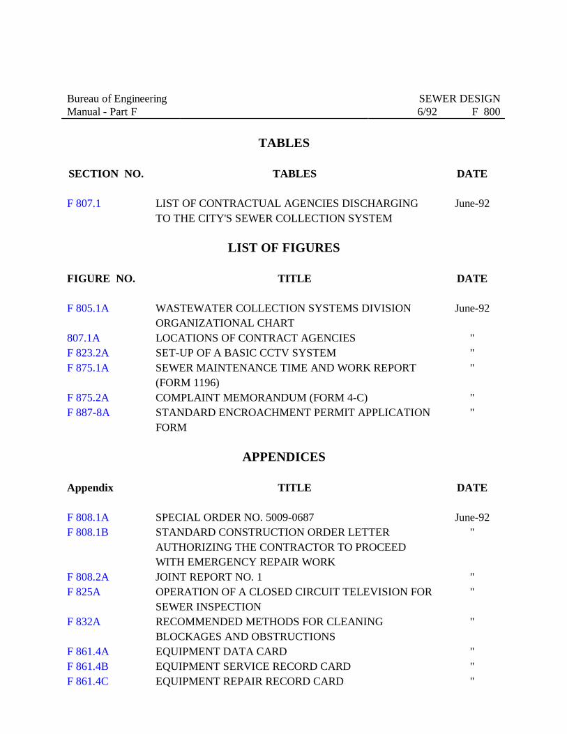
F 807.1 LIST OF CONTRACTUAL AGENCIES DISCHARGINGTO THE CITY'S SEWER COLLECTION SYSTEM
June-92
LIST OF FIGURES
FIGURE NO. TITLE DATE
F 805.1A WASTEWATER COLLECTION SYSTEMS DIVISIONORGANIZATIONAL CHART
June-92
807.1A LOCATIONS OF CONTRACT AGENCIES "F 823.2A SET-UP OF A BASIC CCTV SYSTEM "F 875.1A SEWER MAINTENANCE TIME AND WORK REPORT
(FORM 1196)"
F 875.2A COMPLAINT MEMORANDUM (FORM 4-C) "F 887-8A STANDARD ENCROACHMENT PERMIT APPLICATION
FORM"
APPENDICES
Appendix TITLE DATE
F 808.1A SPECIAL ORDER NO. 5009-0687 June-92F 808.1B STANDARD CONSTRUCTION ORDER LETTER
AUTHORIZING THE CONTRACTOR TO PROCEEDWITH EMERGENCY REPAIR WORK
"
F 808.2A JOINT REPORT NO. 1 "F 825A OPERATION OF A CLOSED CIRCUIT TELEVISION FOR
SEWER INSPECTION"
F 832A RECOMMENDED METHODS FOR CLEANINGBLOCKAGES AND OBSTRUCTIONS
"
F 861.4A EQUIPMENT DATA CARD "F 861.4B EQUIPMENT SERVICE RECORD CARD "F 861.4C EQUIPMENT REPAIR RECORD CARD "

F 861.4D MOTOR SERVICE RECORD CARD "
Bureau of EngineeringManual - Part F
SEWER DESIGN6/92 F 800
F 800 GENERAL
Operation and maintenance of a wastewater collection system means making sure that the system iskept in good operating condition. It requires that the facilities be adequately maintained, so that thesystem can efficiently accomplish its intended function of collecting and conveying wastewater to thetreatment plant in a sanitary manner.
Provision of an adequate operation and maintenance of a wastewater collection system extendsbeyond that of the operation. An efficient system involves joint responsibility of the planners, thedesigners, the construction managers and the administration, acting homogeneously. The operatorcan only function on the basis of available resources provided to him. The greater part of theresponsibility lies with those who plan and build the system.
F 801 PURPOSE AND SCOPE
The purpose of this chapter is to outline the procedures, practices, and policies in the operation andmaintenance of a wastewater collection system. The intent is to serve as a guide for sewer designers,planners and program managers.
The chapter discusses the various aspects of operation and maintenance, and is divided into thefollowing topics:
a. Sound basic policy guidelines;
b. Operations;
c. Inspection and testing;
d. Maintenance;
e. Failures;
f. Remedial measures;
g. Records and logistics;
Bureau of EngineeringManual - Part F
SEWER DESIGN6/92 F 800
h. Emergency operations, maintenance and repairs; and
i. Safety.
F 802 THE NEED FOR ADEQUATE OPERATION ANDMAINTENANCE
A wastewater collection system is subject to a variety of operational problems. Depending on thewastewater flow characteristics, surrounding soils condition, and quality of construction, the pipelinecan suffer from clogging, scouring, corrosion, collapse, and, ultimately, the system's deterioration. The collection system is designed to serve for a specific useful life. Hence, it is incumbent for theCity to provide adequate operation and maintenance to maximize the benefit throughout its designeduseful life.
F 803 POLICY GUIDELINES
It is the policy of the City to protect the public from potential health hazards arising from wastewaterdischarges. To achieve this objective, the following guidelines are set forth:
a. Adoption of a preventive maintenance program to maintain the integrity of thewastewater collection and treatment system.
b. Regular facilities inspection for physical damage followed by immediate and adequaterepairs.
c. Immediate response to all sewer-related complaints followed by prompt correctionof defective condition.
d. Implementation of a sound safety program.
e. Respect for public ownership in the pursuit of sewer maintenance work.
f. Maintenance of good public relations through community participation in theplanning process.

Bureau of EngineeringManual - Part F
SEWER DESIGN6/92 F 804
F 804 DESIGN CONSIDERATIONS FOR OPERATIONAL CONTROL
Operation and maintenance is, and properly should be, a major concern of the design engineer. Aproperly-designed wastewater collection system will minimize operation and maintenance problemsas well as keeping construction costs at a minimum. While maintenance problems can be expected,there are recognizable ones that are design-related. For a complete discussion on design standards,refer to Chapters F200 and F400.
As a general rule, design engineers should adhere, as closely as practicable, to accepted designstandards and codes of practice. Any deviation from these standards should always be done inconsultation with operating and maintenance personnel.
F 805 SEWER COLLECTION SYSTEM MANAGEMENT
The City charter empowers the City Council to provide sewers and appurtenance for sanitarypurposes in order to promote the peace, health, safety and welfare of the public. The Department ofPublic Works is responsible for managing the City's wastewater collection and treatment system.
F 805.1 BUREAU OF ENGINEERING
The Bureau of Engineering is responsible for the planning, preparation of environmental assessment,preliminary designs, final plans and specifications and estimates for all storm drains, sewers andwastewater treatment facilities and other public works infrastructure projects.
F 805.11 WASTEWATER PROGRAM MANAGEMENT DIVISION (WPMD)
The WPMD provides centralized advance planning, scheduling, financial management, technicaloverview and administrativesupport for the entire Wastewater Program. These responsibilities include coordinating andmonitoring:
a. The implementation of an operation and maintenance management system;
Bureau of EngineeringManual - Part F
SEWER DESIGN6/92 F 805
b. The timely submittal by contractors of operation and maintenance manuals; and
c. The training of operation and maintenance personnel.
F 805.12 WASTEWATER SYSTEMS ENGINEERING DIVISION (WSED)
WSED is responsible for the planning and design of all wastewater system facilities, except that ofthe Hyperion Treatment plant. The planning team functions within the Bureau's Wastewater SystemsEngineering Division. The Division is comprised of professionals with backgrounds in sewer, pumpstation, wastewater treatment plant, and sewer designs, hydraulics, environmental analysis andfinancial reporting.
F 805.13 HYPERION ENGINEERING DESIGN DIVISION (HEDD)
The HEDD is responsible for the planning and design of the Hyperion Treatment facilities.
F 805.2 BUREAU OF SANITATION
The Bureau of Sanitation is principally responsible for the operation and maintenance of all facilitiesrequired for the conveyance and treatment of wastewater, including industrial wastes. Within thisBureau, the Wastewater Collection Systems Division performs all routine inspection, cleaning, andrepair, including emergency maintenance, on both the sanitary and local storm drain systems, and onthe wastewater pumping stations. The Division is headed by a Wastewater Collection Manager II.
The Wastewater Treatment Division is responsible for the operation and maintenance of the upstreamtreatment facilities only. The Hyperion Treatment Plant Division, on the other hand, is responsiblefor the Hyperion Treatment facilities only.
F 805.21 FUNCTIONAL RESPONSIBILITIES
Functionally, the Wastewater Collection Systems Division is divided into three sections: (1) PipelineMaintenance, (2) Mechanical and

Bureau of EngineeringManual - Part F
SEWER DESIGN6/92 F 805
Electrical Maintenance and Operation, and (3) Administrative Sections.
For jurisdictional control, the Pipeline Maintenance Section is subdivided into Zone I and Zone II,each one headed by a Wastewater Collection Manager I. The Mechanical and Electrical Maintenanceand Operation Section operates City-wide and is designated as Zone III. It is also headed by aWastewater Collection Manager I. Figure F 805.1A shows the organizational chart of the Division.
F 805.22 PIPELINE MAINTENANCE
This Section is responsible for ensuring that the sanitary sewer and storm drain systems are operatingproperly. The Sewer Work Group is responsible for the operation and maintenance of the sanitarysewer system.
The City-wide Unit cleans and maintains large sewer lines, operates large equipment, chemicallytreats sewers for root control, performs insect and rodent abatement programs, and performs nightand weekend emergency functions.
A City-wide Night Unit performs a night maintenance program and works principally in areas whereheavy daytime traffic precludes effective maintenance work during the regular work hours.
F 805.23 MECHANICAL AND ELECTRICAL MAINTENANCE AND OPERATION
This Section is subdivided into Mechanical, Electrical and Operation groups. The Section operatesDivision-wide with the Mechanical and Electrical Groups responsible for the maintenance and repairof equipment. The Operation Group operates and maintains the sewage pumping plants and theventilation stations.
F 805.24 ADMINISTRATIVE SERVICES
This Section is responsible for all administrative tasks, including the procurement and distribution ofparts and supplies. It is also responsible for the personnel training program as well as the operationand maintenance of the Division's computer system.
Bureau of EngineeringManual - Part F
SEWER DESIGN6/92 F 805
F 805.3 FIXED FACILITIES
The City's wastewater conveyance system consists of about 6,400 miles of mainline sewers, includingfour major interceptors tributary to the Hyperion Treatment Plant and four major outfalls, namely: North, Central, North Central, and the Coastal Interceptor sewers.
There are approximately 100,000 maintenance holes, 70 pumping stations, 7 ventilation stations andvarious siphons and diversion structures. To maintain this system, the Division operates eight sewermaintenance yards which are spread out around the City.
F 805.4 MOBILE EQUIPMENT
The City uses a variety of both heavy and light mobile equipment in sewer system operation andmaintenance work. These include heavy-duty trucks, light pickups, and a host of sewer cleaningequipment that include hydroflushers, rodding and balling machines, and catch basin vacuummachines. It also employs Closed Circuit Television (CCTV) equipment for sewer inspection. CCTVsewer inspection is the responsibility of the Survey Division. All requests for CCTV inspectionshould be directed to that division.
F 806 REVIEW OF PLANS AND SPECIFICATIONS
Generally, the Wastewater Collection Systems Division review function covers only the major sewerlines, such as interceptors, relief sewers, and outfalls. The review process is limited to theconstruction plans and does not include the specifications. The design of the local and main sewersis usually done by the district offices. However, if they include special structures, such as siphons,diversion, etc., the construction plans should be reviewed by WCSD.
The nature of the operation and maintenance of a pumping plant requires that O&M personnel beconsulted during the planning and design stages. It is, therefore, important that WCSD be involvedin the review of plans and specifications for pumping plants.
Bureau of EngineeringManual - Part F
SEWER DESIGN6/92 F 806
In reviewing the plans, the reviewers should look into the following:
a. size of sewers to handle expected flows and maintenance equipment;
b. sewer route alignment as it relates to pipe sizes, depth of excavation, and maintenanceequipment access;
c. ease of operating and maintaining the system;
d. ability to control potential problems for industrial discharges; and
e. Adequate safeguards against potential accident hazards.
F 807 CONTRACTUAL FLOWS
The City currently provides sewage transport and treatment services on a wholesale basis to 29municipalities, districts or agencies pursuant to Sewage Disposal Contracts (SDC) executed and inforce with each agency. While the terms and conditions vary, each contract, in general, requirespayment of operation and maintenance expenses and capital costs attributable to those componentsof the sewer system used by the agency. The volume of flow discharged into the City's sewer systemis used as the basis for sewer charges.
The wastewater collection systems serving the Terminal Island Treatment Plant (TITP) fall under thejurisdiction of four separate entities: (1) the City of Los Angeles; (2) the Los Angeles CountySanitation District; (3) the Los Angeles Harbor Department, and (4) the United States Departmentof the Navy. Most of the area is served by the wastewater system of the City of Los Angeles.
A section of the City is served by the Los Angeles County Sanitation Districts (LACSD). Twopocket areas of Los Angeles County are located within the TITP service area, and wastewater fromthese areas drain into the collection system of the City.
Bureau of EngineeringManual - Part F
SEWER DESIGN6/92 F 807
A portion of the City of Los Angeles is tributary to the City of Long Beach sewer system. Wastewater from this area is ultimately conveyed to the LACSD joint treatment plant. While acontract between the Cities of Los Angeles and Long Beach permits the City of Los Angeles todischarge a maximum of 3.2 mgd to the Long Beach system, the contract is currently inactive.
F 807.1 CONTRACTUAL AGENCIES
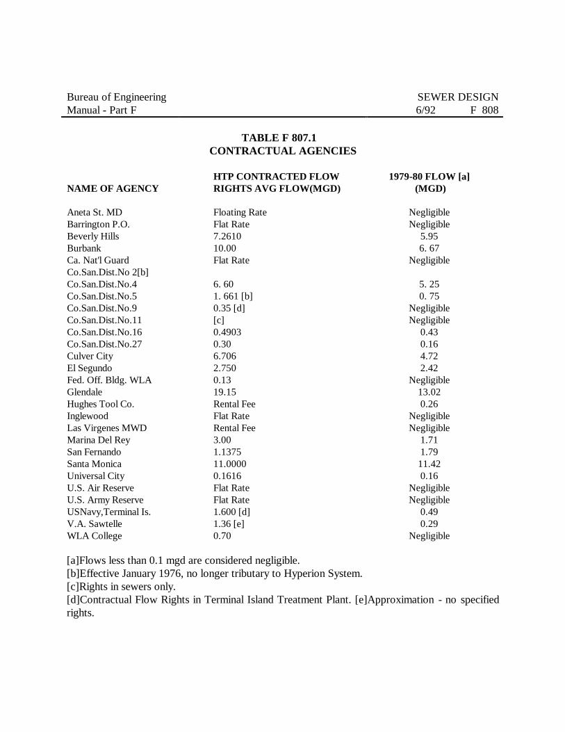
Table F 807.1A lists the contractual agencies discharging their wastewater to the City's sewer system. The list shows the locations of these agencies.
F 808 EMERGENCY SEWER REPAIR WORK
As a matter of policy on public health hazards, the City is committed to employ the services of privatecontractors to perform emergency sewer repair work on failed sewer lines in case the City forces areunable to respond to or handle the scope of work.
As adopted by the City Council on October 17, 1984, and concurred in by the Mayor on October 25,1984, a sewer failure is, by definition, a matter of urgent necessity as defined in the Los Angeles CityCharter, Section 386.
F 808.1 PROCEDURE FOR EMERGENCY SEWER REPAIR WORK
The revised procedure for utilizing a private contractor in emergency sewer repair is spelled out inthe Bureau of Engineering Special Order No. 5009-0687 dated June 8, 1987 shown as AppendixF 808.1A. Appendix F 808.1B is a standard construction order letter authorizing the contractor toproceed with the emergency repair work.
F 808.2 ON-CALL CONTRACTORS FOR EMERGENCY SEWER REPAIR WORK
The authority to establish a list of on-call contractors for emergency sewer repair work is containedin the Bureau of Engineering, Bureau of Sanitation, Bureau of Contract Administration, Office ofContract Compliance joint Report No. 1 shown as Appendix

Bureau of EngineeringManual - Part F
SEWER DESIGN6/92 F 808
F 808.2A dated October 16, 1987 and adopted by the Board of Public Works of the City of LosAngeles on the same date.
A rational list of on-call contractors for emergency sewer repair work is shown as Exhibit A of saidSpecial Order No. 5009-0587. This is continuously updated after each emergency condition.
Bureau of EngineeringManual - Part F
SEWER DESIGN6/92 F 808
TABLE F 807.1CONTRACTUAL AGENCIES
NAME OF AGENCY
Aneta St. MDBarrington P.O.Beverly HillsBurbankCa. Nat'l GuardCo.San.Dist.No 2[b]Co.San.Dist.No.4Co.San.Dist.No.5Co.San.Dist.No.9Co.San.Dist.No.11Co.San.Dist.No.16Co.San.Dist.No.27Culver CityEl SegundoFed. Off. Bldg. WLAGlendaleHughes Tool Co.InglewoodLas Virgenes MWDMarina Del ReySan FernandoSanta MonicaUniversal CityU.S. Air ReserveU.S. Army ReserveUSNavy,Terminal Is.V.A. SawtelleWLA College
HTP CONTRACTED FLOWRIGHTS AVG FLOW(MGD)
Floating RateFlat Rate7.261010.00Flat Rate
6. 601. 661 [b]0.35 [d][c]0.49030.306.7062.7500.1319.15Rental FeeFlat RateRental Fee3.001.137511.00000.1616Flat RateFlat Rate1.600 [d]1.36 [e]0.70
1979-80 FLOW [a] (MGD)
NegligibleNegligible
5.956. 67
Negligible
5. 250. 75
NegligibleNegligible
0.430.164.722.42
Negligible13.020.26
NegligibleNegligible
1.711.7911.420.16
NegligibleNegligible
0.490.29
Negligible
[a]Flows less than 0.1 mgd are considered negligible.[b]Effective January 1976, no longer tributary to Hyperion System.[c]Rights in sewers only.[d]Contractual Flow Rights in Terminal Island Treatment Plant. [e]Approximation - no specifiedrights.

Bureau of EngineeringManual - Part F
SEWER DESIGN6/92 F 810
F 810 OPERATIONS
Operations refers to activities related to managing the City's sewer collection system. This involves6,500 miles of pipeline network, 58 pumping plants and four treatment facilities. Operating such asystem requires a well-organized and highly trained technical, semi-skilled, skilled and administrativestaff to ensure that the system is in continuous operation.
F 811 PIPELINE OPERATIONS
For administrative purposes, pipeline operation has been divided into three working groups. Thesegroups are designated as Zone III, responsible for all mechanical and electrical maintenance, as wellas pumping plant operation. The Administrative Division is responsible for all administrative matters.
F 812 FLOW MEASUREMENTS
The ability to measure wastewater flows is of fundamental importance in the planning and design ofwastewater management facilities. Maintenance planning for a specific pipeline may also require aknowledge of discharge and flow velocity.
F 812.1 RESPONSIBILITY
The Survey Division of the Bureau of Engineering is responsible for conducting flow measurements.
The Sewer Planning, Monitoring and Special Projects Section, Wastewater System EngineeringDivision, coordinates all requests for flow measurements. It is also charged with the responsibility ofcompiling and keeping flow measurements data for all special flow gaging requests and for the routinemonitoring program.
F 812.2 TYPES OF FLOW MEASUREMENTS
There are three types of flow measurements. Depending on what type, gaging period can last fromeight hours to seven days. In general,
Bureau of EngineeringManual - Part F
SEWER DESIGN6/92 F 812
most flow measurements for special gaging request are conducted for 24 hours.
F 812.21 ANNUAL FLOW MEASUREMENTS PROGRAM
This type of flow measurements is categorized as routine gaging. Flow measurements are taken froma network of wastewater sewer maintenance holes covering the City's wastewater collection system.
Flow measurements are taken for eight continuous hours at 30-minute intervals. The frequency variesfrom one to four times a year for each gaging station, depending on the planning requirement.
F 812.22 REGULAR MONITORING OF CONTRACTUAL FLOWS
The City maintains flow gaging stations for contract agencies and cities discharging to the City'swastewater collection system.
Flow measurements are taken at each gaging station for seven continuous days on a quarterly basis. All data are sent to the Financial Management and Control Group, Wastewater ProgramManagement Division (WPMD).
F 812.23 SPECIAL GAGING REQUESTS
These are requests initiated by various City offices. In general, the majority of requests originate fromthe Bureau of Engineering district offices and from the Wastewater System Engineering Division(WSED).
Flow measurements are generally conducted for 24 hours, but can extend to seven days dependingon need and flow variations.
F 812.3 METHODS OF MEASUREMENTS
There are 2 principal methods of measuring flow: (1) direct discharge method, and (2) velocity-areamethod. For direct discharge method, the rate of discharge relates to one or two easily measurablevariables.
Bureau of EngineeringManual - Part F
SEWER DESIGN6/92 F 812
The Survey Division employs the direct discharge method for flow measurements. Two types of flowmeasuring devices, the F-3000A Manning flowmeter and an Ultra Sonic System are used. Bothdevices measure directly the depth of flow. For routine gaging, and for pipe sizes eight inches andsmaller, the handgaging method is used.
F 812.4 PROCEDURE FOR REQUESTING FLOW MEASUREMENTS
All requests for sewer gagings shall be directed to the Survey Division. Such requests are to becompleted on the Standard Survey Division field request forms. The requests shall be accompaniedby a copy of that portion of the sewer "Y" maps that includes all of the maintenance holes to begaged; each maintenance hole shall be circled on the "Y" map(s) for easy identification.
All sewer maintenance holes to be gaged shall be physically located in the field and inspected as totheir suitability to be gaged, prior to making the sewer gaging request. Any unusual problems thatmay be involved, such as heavy traffic, unusual peak hours for sewage flow, large size or tarredmaintenance hole covers, or maintenance holes not located in City streets or easements should alsobe noted on the sewer gaging request. If the maintenance hole is not located in a City street oreasement, permission to gauge shall be obtained by the requesting office.
Where feasible, requests for sewer gaging information required for high priority work or emergencies,may be transmitted by telephone, but must be immediately followed by written field work request tothat effect.
The Survey Division shall send copies of the resulting gaging information to the requesting office andto WSED. However, for jobs of high priority or emergencies, the results of the sewer gaging mayfirst be made available by the Survey Division to the requesting office by telephone.
F 813 PUMP STATION OPERATION
The main function of a pump station, sometimes called lift station, is to raise wastewater from a lowerto a higher elevation. A pump
Bureau of EngineeringManual - Part F
SEWER DESIGN6/92 F 813
station discharges into a long force main whereas a lift station has a relatively short discharge lineimmediately preceding the downstream gravity sewer. As used in this manual, pump station includeslift stations.
The ideal operation of a pump station would be when the discharge rate is nearly equal to the inflowrate. This would occur with the highest use of equipment and energy efficiency possible. Consequently, operational and maintenance problems would be minimized.
For discussion on pump station design considerations, refer to Chapter F700.
F813.1 RESPONSIBILITY
The operations group in the Mechanical, Electrical and Operation Section is responsible for theoperation and general upkeep of the pump stations and the ventilation stations. A senior electricalplant operator supervises the whole operation, and is responsible for scheduling the work on amonthly basis.
F813.2 MODE OF OPERATION
There are three modes of operation used in the operation of the pump stations. Each one is describedbelow:
a. Automatic Control Operation. This is the normal mode of operation. This consistsof the activation and deactivation of a series of pumps depending on the wastewaterlevel in the wet well.
Primary controls, such as floats, air bubbles or pressure sensitive devices, measure thelevel of water in the wet well. Secondary controls convert the measurement from theprimary controls into a signal for a pump to start, stop, or change speed.
b. Constant Speed Operation. This mode is used as an alternate to the automatic controltype of operation.

Bureau of EngineeringManual - Part F
SEWER DESIGN6/92 F 813
The pumps may be set manually to operate at a desired constant speed. This modeis used under one of the following conditions:
(1) When the normal mode of operation fails;
(2) When testing any section of the pump operating system;
(3) During any unique situation when the pumps maybe operated in order toregulate the wastewater inflow;
(4) During any unusual or emergency situation.
c. Fill and Draw Operation. This mode of operation serves as a backup system when the"automatic control" mode fails due to malfunction in the wastewater level gagingsystem in the wet well. During such failure, and if no personnel is available to activatethe "constant speed" system, the "Fill and Draw" mode of operation is automaticallyactivated by means of a switch at a predetermined wastewater level in the wet well. When such situation occurs, an emergency situation is telemetered to the plant mainheadquarters in Venice. Maintenance personnel is then notified so that correctiveaction can be initiated.
In every case, after corrective action has been taken, the maintenance personnel needsto restore the mode of operation to the normal "automatic control" system.
F813.3 PUMP STATION VISIT
Depending on the type (e.g., package type), size, and capacity of a pump station, the facility maybefully-manned 24 hours a day or operated unattended except for regular periodic visits. A fullymanned pump station does not pose as much maintenance problem as an unattended one since anoperator is always present to take care of any breakdown.

Bureau of EngineeringManual - Part F
SEWER DESIGN6/92 F 813
For the unattended pump station, the frequency of inspection varies depending on the following:
a. Design of the facilities and type of equipment installed. Some recorder's charts needto be replaced once every three days, whereas others can run unattended for as longas a week.
b. Condition of equipment, which could be one that has been temporarily repaired andwaiting for replacement parts.
c. Adequacy of preventive maintenance program.
d. Availability of operating and maintenance personnel.
In general, most of the pump stations are visited every 72 hours for operational needs. During suchvisit, the Pump Operator performs all operational checks, including the replacement of recordingcharts, making sure that all the pumps are operational, and that the pumps are not "airbound".
For general upkeep, the stations are visited once a week or as manpower availability allows.
F813.31 SAFETY
One rule that should apply to all pump station visits is that for safety precautions, there must alwaysbe two operators making the station visit.
Safety precautions regarding the presence of hazardous gases apply not only on the wet well, but inthe dry well area of the station, too. This rule must be followed, particularly during off duty hourssuch as night time, weekends, and holidays when operators are responding to pump station telemetryalarms.
For safety procedures in confined space, refer to Section F880.

Bureau of EngineeringManual - Part F
SEWER DESIGN6/92 F 813
F813.32 SIGN-IN LOG
Every pump station should have a sign-in log. Everyone who enters the station should sign the plantlog book, including the date and time of arrival and departure. This allows for monitoring everyactivity that takes place inside the station. The sign-in log should be kept inside the station and turnedinto the office when the last space on the sign-in sheet is exhausted.
F813.4 RESPONDING TO STATION ALARMS
The responsibility of responding to "Red" alarms for unattended stations lies with the operator onduty in the central receiving station at the Venice Pump Station. This station is manned 24 hours aday and all stations are connected to it by telemetry.
The unmanned pump stations are continuously monitored for any signal which will indicate anychange from normal condition. An hourly check is made of the overview display to ensure that allstations are operating normally.
F813.5 TYPES OF ALARM CONDITION
There are eight types of alarm condition that could warrant emergency responses. Each one of theseindicates an abnormal condition where the alarm originates.
F813.51 POWER FAILURE
This condition indicates electric power outage at the station where the signal originates. Loss ofelectric power for an unextended period results in a complete shutdown of the pumps. When thisoccurs, a signal is automatically transmitted to the central receiving station at Venice Pumping Plant.
F813.52 HIGH WATER WET WELLThere are several possible causes that could result in this condition. A high water alarm could be dueto:

Bureau of EngineeringManual - Part F
SEWER DESIGN6/92 F 813
a. Power failure;
b. Improper arrangement of electric controls;
c. Failure of automatic control;
d. Obstruction in a pump;
e. Obstruction in the piping system;
f. Improper arrangement of valves; or
g. Hydraulic overload due to excessive inflow and/or infiltration as a result of an intenserainfall.
F813.53 WATER ON DRY WELL
This condition could be due to:
a. Breakdown of the sump pump;
b. Excessive bleed-off from the pump packing; or
c. Leak from the piping system.
F813.54 COMMUNICATION FAILURE
This condition occurs when the scanning equipment at the Venice Pumping Plant is not receiving anysignal from the unattended stations. While this could be caused by a failure of the leased telephoneline serving the particular station, it could also be the result of a complete failure of the remotestation's transmitting equipment. Such failure would most likely be caused by the inability of theemergency battery to function during a power outage from the regular power source.
F813.55 PLANT ABNORMAL
This condition indicates the failure of the wastewater level gaging system in the wet well to functionproperly. Under normal

Bureau of EngineeringManual - Part F
SEWER DESIGN6/92 F 813
condition, the station will start operating off the Murphy switch, sending in high water level wetalarms when the wet well level reaches a pre-determined elevation.
F813.56 DEVICES CYCLING
This condition indicates that a pump is cycling on and off. The alarm comes in each time the pumphas cycled for the fourth time in the preset time period.
F813.57 DOOR OPEN
This condition simply indicates that the door to the pump station is open. When this condition occursat any time other than regular working hours, it should be reported.
F813.58 MESSAGE 1 OR 2
This condition indicates that an electrician (Message 1) and/or mechanic (Message 2) is at the plant. If this condition occurs at any time other than regular working hours, it should be reported on thefollowing working day.
F813.59 ALL ALARMS CONDITION
This condition is usually caused by a malfunction of the telemetry equipment at that particular station. When this happens, all the alarm functions (i.e., power failure, high water in wet well, water in drywell, communication failure, plant abnormal, device recycling, and door open) are set in motion andtelemetered to the central receiving station.
F813.6 GENERAL RESPONSE PROCEDURE
Response procedure may vary depending on the type of alarm received. However, in general, theoperator on duty at the Venice Pumping Plant is required to:
a. Notify the appropriate WCSD Supervisor;

Bureau of EngineeringManual - Part F
SEWER DESIGN6/92 F 813
b. Continue monitoring the station; and
c. Notify the supervisor previously notified when the "alarm" status ends.
The operator on duty is also required to record in the Log Book the following data: Date, time,location, nature of the alarm, and the name of the person notified.
F 814 TREATMENT PLANT OPERATION
The City operates four major wastewater treatment facilities with a combined wastewater design flowtreatment capacity of 510 mgd. These facilities include the Hyperion Treatment Plant (HTP),Terminal Island Treatment Plant (TITP), Los Angeles-Glendale Water Reclamation Plant(LAGWRP), and the Tillman Water Reclamation Plant (TWRP). TITP, LAGWRP, and TWRP arereferred to as the upstream facilities.
All four treatment facilities are of the conventional activated sludge process, providing secondarytreatment, except LAGWRP and TWRP, which have the added feature of a tertiary treatmentprocess.
The purpose of this section is to provide an overview of the operational features of these facilities,including capacity, type, effluent and sludge disposal methods.
F 814.1 HYPERION TREATMENT PLANT (HTP)
The Hyperion Treatment Plant, located in Playa Del Rey, is the largest of the four treatment facilities.It has a primary treatment capacity of 420 mgd. Currently, 150 mgd undergoes secondary treatment.It also provides solids handling for incoming sludge transported in the wastewater collection systemfrom upstream facilities.
A unique feature of the HTP is the energy recovery system, otherwise called HERS. This system isdesigned to digest, dewater, dry, and then combust the sludge, resulting in the recovery of energy.This makes the plant self-sufficient in energy requirement,

Bureau of EngineeringManual - Part F
SEWER DESIGN6/92 F 814
with the capabilities of being able to sell surplus power. The effluent is discharged into the ocean bya five-mile outfall.
F 814.2 TERMINAL ISLAND TREATMENT PLANT (TITP)
The Terminal Island Treatment Plant has a daily average full secondary design capacity of 30 mgd.Currently, the plant provides full secondary treatment for a daily average flow of 20 mgd serving theindustrialized Los Angeles Harbor area. The effluent is discharged into the harbor through a 6,000foot outfall.
There are three major factors that differentiate this plant from the other two upstream facilities.
a. The plant handles a high proportion of industrial waste.
b. It has its own solids handling facilities.
c. It is completely exposed to a corrosive environment, being located in a saltwatersurrounding, sited just 12 feet above sea level.
F 814.3 TILLMAN WATER RECLAMATION PLANT (TWRP)
This plant serves the San Fernando Valley area and is designed to treat 40 mgd. The plant is beingexpanded to an additional 40 mgd. This is scheduled to be operational by 1991.
The plant is a model facility, with state-of-the-art instrumentation and control, and a landmarkJapanese garden.
The treatment system includes a tertiary process, producing an effluent to irrigation water standards.A portion of the reclaimed water is used for landscape irrigation and in the lakes of the Japanesegarden. The remainder is discharged into the Los Angeles River. The plant does not have solidshandling facilities; it conveys the sludge by sewer line to the Hyperion Treatment Plant.

Bureau of EngineeringManual - Part F
SEWER DESIGN6/92 F 814
F 814.4 LOS ANGELES-GLENDALE WATER RECLAMATION PLANT (LAGWRP)
This plant is designed to treat 20 MGD and serves the northeastern section of the City, including aportion of the Cities of Glendale and Burbank. This facility is jointly-owned and financed with theCity of Glendale.
The treatment system includes a tertiary process which treats the secondary effluent to irrigationwater standards. Part of the reclaimed water is used for industrial cooling and golf course and freewayirrigation. The remainder is discharged into the LA River. The plant does not have solids handlingfacilities. Instead, it conveys the sludge by sewer line to the Hyperion Treatment Plant.
Bureau of EngineeringManual - Part F
SEWER DESIGN6/92 F 820
F 820 INSPECTION AND TESTING
An effective way of establishing good public relations is to ensure the proper functioning of thewastewater collection system. Hence, it is important that the operation and maintenance personnelcontinuously monitor the condition of the collection system. Inspection and testing provide the meansfor the monitoring activity.
F 820.1 OBJECTIVES
The objectives of sewer inspection and testing are:
a. To identify existing or potential problems in the collection system;
b. To pinpoint the location of the problems;
c. To evaluate the seriousness of the problems;
d. To correct the problem; and
e. To provide accurate and meaningful reports regarding the problems.
F 820.2 RESPONSIBILITY
The responsibility of inspecting and testing the wastewater collection system lies with WCSD. Sewerinspection crews within the Pipeline Maintenance Section regularly inspect the pipeline to ensure thatthe system is in good working condition.
F 821 SURFACE INSPECTION
The inspection program is primarily a visual one made from street level. The inspection crews lookfor flooded or sunken areas, surface cracks on the ground along the sewer line route, signs ofvandalism, damage to special structures and maintenance holes, maintenance hole covers higher orlower than the pavement level in the streets, and evidence of flooding or seepage from sewers.

Bureau of EngineeringManual - Part F
SEWER DESIGN6/92 F 822
F 822 MAINTENANCE HOLE INSPECTION
As an integral part of the sewer collection system, maintenance holes require the same degree ofinspection and maintenance as the rest of the sewer network. WCSD has established an annualmaintenance hole inspection schedule as part of the sewer inspection and maintenance program. Thepurpose is to check for defects. All maintenance holes in the City are inspected on a cyclical basis.The inspection is generally visual, with the inspection crew checking the maintenance hole cover, ring,barrel, steps, and the bottom surface for any defective condition.
F 822.1 OBJECTIVES
Maintenance holes are inspected for the following purpose:
a. To check for obstruction, debris in line & maintenance hole, grease, etc.;
b. To ensure that the maintenance hole lid is in proper grade or elevation;
c. To ensure that the lid has not been buried by street resurfacing work; and
d. To maintain the structural integrity of the maintenance hole (i.e., by checking for thepresence of cracks.)
F 822.2 FREQUENCY OF INSPECTION
Existing maintenance holes should be inspected once every year to ensure that they are in goodcondition. Old maintenance holes must be inspected as often as possible to detect leaks that createinflow/infiltration problems.
Under the WCSD maintenance hole inspection program, each maintenance hole is inspected at leastonce every 10 months within the year.

Bureau of EngineeringManual - Part F
SEWER DESIGN6/92 F 822
New maintenance holes need to be thoroughly inspected in the same manner as the rest of the sewerline before acceptance.
F 823 PIPELINE INSPECTION
WCSD employs both visual and closed circuit television in its pipeline inspection program. Routinesewer inspection procedure has been developed for use by the sewer inspection crew.
F 823.1 DIRECT VISUAL INSPECTION
Visual inspection involves a sewer inspection crew walking through large diameter pipelines (36-inchdiameter and larger) to check for cracks, pipe or joint separations, corrosion, root intrusion, obstruc-tion, and other pipeline defects not normally visible from on-surface inspection. Extreme care shouldbe taken to provide adequate safety measures as discussed in Section F 880, Safety. Inspectors canuse manually operated cameras for detailed pictures or illustrations for reports, instructions, ormaintenance work.
F 823.2 CLOSED CIRCUIT TELEVISION INSPECTION (CCTV)
Closed circuit television inspection provides the most positive and reliable information on the internalcondition of a small diameter sewer line. Permanent records of the inspection can be made by photo-graphing the TV screen or by using video tape. CCTV inspection capability extends to pipes of allsizes, down to 4-inch diameter pipes. Knowledge of the TV equipment and its capabilities, as wellas the operator's skill in interpreting the recorded information, are very important.
Basically, a CCTV unit would consist of the following components:
a. Television camerab. Floodlightc. Camera carrying skidsd. Multi-conductor power and video cablee. TV picture monitorf. System power control center or moduleg. Portable power source, usually a portable generator

Bureau of EngineeringManual - Part F
SEWER DESIGN6/92 F 823
h. Pulley assembly with two winch standsi. Cable reel and footage meterj. Service truck containing the TV power control and picture monitork. Sound-powered telephone systeml. Video tape recording equipment (optional)m. Polaroid camera for still picture (optional)n. Overnight cable
Figure F 823.2A shows a set-up of a basic CCTV system.
A detailed description on how a closed circuit TV inspection operates is given in Appendix F-I.
F 824 TESTING
Testing is one of the methods used to gather information to develop a sewer operation andmaintenance program. It is also used to detect leaks in the sewer line (e.g., smoke testing). There areseveral methods of testing a sewer line. Each has its own applicability.
F 824.1 SMOKE TESTING
Smoke testing consists of blowing smoke through a section of pipelines isolated from the rest of thesystem by plugging the pipes at both ends of three successive maintenance holes. Smoke testing isbest applicable when the groundwater is low, so that any crack will leak smoke.
F 824.11 OBJECTIVES
Smoke testing is used in wastewater collection system to determine:
a. Points of entry of surface inflow to the collection system;
b. Location of illegal connections (e.g., down-spouts, drains, industrial drains, etc.) tothe wastewater collections system; and

Bureau of EngineeringManual - Part F
SEWER DESIGN6/92 F 824
c. Location of broken sewers due to settling of foundations, maintenance holes and otherstructures.
F 824.12 EQUIPMENT
The following is standard equipment in a smoke testing operation:
a. Smoke blower unit. The blower is usually a gasoline belt-driven unit, with averageblower capacity between 1,700 CFM and 3,000 CFM. The blower will have a basewith a rubber gasket underneath the base that allows it to set over and force a blastof air into an open maintenance hole.
b. Pipe plugs to isolate two sections of pipe between three successive maintenance holes.The plugs may either be mechanical or inflatable.
c. Smoke bombs. These are available in up to 15-20 minute durations.
F 824.13 STAFFING
The average smoke testing crew will consist of five persons. One will be in charge and four will serveas observers and recorders.
F 824.14 THE NEED FOR PUBLIC NOTICE
Smoke testing of a sewer line could adversely affect the occupants of buildings connected to thesewer line being tested. There are a number of ways smoke could enter the building. These includedefects in the building sewer system, dry taps, defective wax ring under the commodes, ventsterminating in an attic, or missing clean-out plugs from the building sewer system. To avoid panic orundue alarm, the residents of the area to be smoke-tested should be advised of the scheduled testingahead of time. A minimum of three days lead time should be allowed.
The City Fire and Police departments should also be notified at the start of each day of the scheduledtesting. It is advisable to have

Bureau of EngineeringManual - Part F
SEWER DESIGN6/92 F 824
a fire vehicle from the Fire Department accompany the testing operation.
F 824.2 DYE TESTING
Dye testing consists of applying dye to a sewer line and tracing its movement as it flows through thesewer system. Typical applications of the dye testing include the following:
a. Buildings that may not show smoke at vents during the smoke test due to dips or trapsin the service connection pipes;
b. Where a yard drain or storm drain is suspected of being tied to the building sewer ora lateral sewer;
c. Any suspected surface inflow to the wastewater collection system;
d. Testing for infiltration and exfiltration; and
e. Flow velocity measurements.
F 824.21 EQUIPMENT
There are two types of safe and harmless but effective dyes available for dye testing. The dye comesin either powder or tablet forms. The tablet type is slower to dissolve than the powder form, but isless messy.
The State Water Resources Control Board (SWRCB) should be contacted to determine if there areany regulations regarding the use of dyes. SWRCB should also be notified anytime dye gets into thestorm drain.
F 824.22 STAFFING
Two workers are required to conduct a dye test. One operator applies the dye to the suspectedlocation while another maintains a watch at the next downstream maintenance hole from the location.

Bureau of EngineeringManual - Part F
SEWER DESIGN6/92 F 824
F 824.3 PIPELINE LAMPING
Pipeline lamping consists of looking directly through a section of the sewer line or by the aid of amirror. The purpose is to determine whether or not the section of the sewer line being lamped isstraight and open. It also allows an inspector to visually examine the condition of the pipe withinviewing distance of the maintenance hole.
Lamping, while providing only limited information, has considerable value in collection systemmaintenance. It is an economical and fast method of determining if a line is straight and clear; other-wise, it will expose imperfections in the line. Lamping is fast and cheap, if it can be used. However,lamping should never be used for any purpose other than for alignment. The existence of cracks, infil-tration or other pipe problems are difficult to detect by this method.
As a word of caution, lamping can be hazardous anytime a worker enters a maintenance hole. Hence,there should always be two people working on top of a maintenance hole.

Bureau of EngineeringManual - Part F
SEWER DESIGN6/92 F 830
F 830 MAINTENANCE
Maintenance of the wastewater collection system is one of the major tasks of the WastewaterCollection Systems Division. The objective of a good maintenance program is to keep the system ingood operating condition so that it can function efficiently throughout its design life. Lack of goodmaintenance can result in serious health hazards to the public. It can also cause damage to privateproperty due to sewer backups and overflows. Additionally, it could expose the City to liability suitsarising from such hazards and property damage.
F 831 TYPES OF MAINTENANCE
Maintenance can be categorized into preventive and corrective maintenance. Preventive maintenanceinvolves inspection of the collection system and analysis of existing data to identify trouble areas. Thiscan provide guidance in developing the type, degree, and frequency of preventive maintenancerequired.
Corrective maintenance refers more to emergency maintenance. This can be an actual collapse of anexisting sewer; stoppage due to roots, grease, or other foreign materials; or excessive inflow orinfiltration. These conditions require immediate action to correct the problem. The objectives are toimprove service, reduce emergency occurrences, and to minimize the cost of the preventive mainten-ance program.
In general, the greater the amount of preventive maintenance performed, the less the amount ofcorrective maintenance that will be required. However, there should be a reasonable balance betweenthe cost of preventive maintenance and the corresponding benefit derived. While no precise methodis available to determine just exactly how much preventive maintenance should be undertaken, areview of historical maintenance costs on similar facilities can serve as a useful guide to planners anddesigners.

Bureau of EngineeringManual - Part F
SEWER DESIGN6/92 F 832
F 832 PIPELINE MAINTENANCE
WCSD has developed a year-round pipeline maintenance program. The emphasis is on preventivemaintenance. Under the program, sewers, including maintenance holes, pumping plants, and specialstructures, are regularly inspected. Known trouble locations are checked at more frequent intervals.
Pipeline maintenance crews, operating City-wide, clean and maintain large sewer lines, chemicallytreat sewers for root control, and perform insect and rodent abatement work.
F 833.1 CAUSES AND TYPES OF BLOCKAGES
The most frequently received complaints about sewers are blockages. A blockage is confinedprincipally to small diameter sewers not accessible for a maintenance worker to enter.
Blockages or obstructions can be caused by sand and gravel deposits, garbage from garbage grinders,disposable diapers, personal hygiene products, grease build-up, heavy settled debris, debris held bya line break, a slipped joint, illegal taps that protrude into the sewer pipe, or any other condition thatreduces or restricts the flow.
The recommended methods for cleaning blockages or obstructions depend on the nature and causesof the problems. A table listing types of blockages and obstructions, effective methods of removal,and evaluation of each method is given in Appendix F 832A.
F 834 MAINTENANCE METHODS
Pipeline cleaning and maintenance methods depend on the wastewater characteristics, fluctuationsin flows, sewer alignment and grade, pipe material, condition of the sewer, the type of area beingserved, and most importantly, past history of sanitary sewer performance.
An effective preventive maintenance program can only be achieved with a complete set of records.The records should indicate the
Bureau of EngineeringManual - Part F
SEWER DESIGN6/92 F 834
causes of all blockages, size of the sewer, history of past blockages and corresponding preventivemaintenance, including the type of maintenance equipment used to perform the maintenance work.
Blockages can be cleared or prevented and sewers cleaned by either hydraulic or mechanical methods.Chemicals are also a tool used to help control root growth in sewer lines.
Hydraulic methods consist of cleaning sewers with water under pressure that produces high watervelocities. These velocities are usually high enough to break up the blockage and flush most grit,grease, and debris.
Mechanical methods consist of using equipment that scrapes, cuts, pulls or pushes the material outof the pipeline.
The following briefly describes the most commonly used cleaning methods, including theirapplicabilities and limitations.
F 834.1 RODDING
The equipment may either be a power rodding machine (may be truck or trailer-mounted) or handrods.
Power rodding involves applying a torque to a steel rod as it is pushed through the line, rotating thecleaning device attached to the lead end of the rod.
This method can be used for routine preventive maintenance, such as breaking up of grease deposits,cutting roots, loosening debris, threading cable for bucket machines or TV inspection equipment, andfor emergency removal of blockages.
The method is fairly efficient in lines up to 12 inches in diameter but is less useful in larger lines. Themethod is ineffective for removing sand and grit accumulations, but may loosen the material so it canbe flushed out of the sewer. The rod has a tendency to coil and bend when used in large diametersewers. Electrically-powered power rodding machine is also available and can be used in smallerlines.
Bureau of EngineeringManual - Part F
SEWER DESIGN6/92 F 834
F 834.2 BALLING
This equipment consists of an assortment of various sizes of sewer balls to fit different diameters ofsewers, a tag line, winch, cable, reels, a water source, and a dump pick-up.
The method utilizes the pressure of a water head to create high-velocity water flow around the ball.It is very effective in removing heavy concentrations of sand, grit, rock, and grease from the sewers.Balls are available in sizes from 6 to 48 inches. This method is not recommended for locations withbasement fixtures and in steep-grade hilly areas because of possible flooding of connected buildings.It cannot be used effectively when sewers have bad offset joints or protruding service connectionsbecause the ball can become lodged in the pipe, becoming distorted, thereby preventing it from doingan effective cleaning job.
F 834.3 FLUSHING
This is an inefficient hydraulic method that can be used at the upstream location of a collection systemwhere low or sluggish flow results in deposition of solids. It is now rarely used since the introductionof the high-pressure water jet cleaners. A fire hydrant is normally used for this procedure. However,if a fire hydrant is not accessible, the equipment may consist of a water tank and a fire hose.
The method is effective in removing floatables and some sand and grit. It is useful in combination withmechanical operations such as rodding or bucket machine cleaning.
The method is not very effective in removing heavy debris and grit. It is not recommended for usein locations with basement fixtures and steep-grade hilly areas because of possible flooding ofconnected buildings.
F 834.4 JETTING
This is a hydraulic method of cleaning sewers which directs high velocity streams of water againstthe pipe walls at various angles.

Bureau of EngineeringManual - Part F
SEWER DESIGN6/92 F 834
The equipment consists of a truck-mounted high velocity water machine, maintenance hole hoseguide, debris traps, and a dump pick up or debris trailer.
The method is very effective in cleaning flat, slow flowing sewers. It is very efficient in removinggrease, sand, gravel, and debris deposits in small sewers. It is also effective in breaking up solids inmaintenance holes, and in washing structures. The effectiveness in removing debris, however,decreases as the size of the pipe increases.
F 834.5 SCOOTER
This is a hydraulic method of cleaning a sewer line. The equipment consists of a scooter assembly,water tank truck, dump pick-up truck, tag line and a power winch.
The scooter itself is a steel framework on small wheels with a rubber-rimmed, round metal shield atone end. The top half of the shield is hinged and is controlled by a chain-and-spring system; the lowerhalf is rigidly attached to the scooter frame. In operation, the shield acts as a plug to build a head ofwater. The pressure of the water behind the shield moves the scooter downstream, but the cablerestrains it, allowing slow smooth progress downstream while the water forces past the shield rim andscours the pipe wall in somewhat similar manner as the balling method. The high turbulence forcesloosened debris to move downstream to be caught by the trap at the next maintenance hole.
This method is very effective in removing heavy debris. The method is used for large diameter pipes,usually storm drains. Caution must be used in locations with basement fixtures and steep-grade hillyareas because of possible flooding of connected buildings.
F 834.6 KITES, BAGS, TIRES AND POLY PIGS
Kites, bags, tires, and poly pigs are devices more suited for hydraulically cleaning larger sanitarysewers in a manner similar to the balling method.
Bureau of EngineeringManual - Part F
SEWER DESIGN6/92 F 834
The basic equipment includes a water tank truck, dump pick-up truck, and a power drum machine.The rigid rims of bags and kites cause the scouring action. The kite's shape creates a forward jet ofwater that scours the pipe wall. A tire, approximately two inches smaller in diameter than the pipe,rigged to a restraining line, will respond to two feet or more head of water like a sewer ball. The polypig is used for very large sanitary sewers and is not restrained by a line, but moves through the pipesegment with the water pressure built up behind it. Poly pigs are frequently used for cleaning forcemains.
The devices are very effective in moving accumulations of decayed debris and grease downstream.They are also capable of washing ahead of it a full pipe of deposits, including roots.
Caution must be used in locations with basement fixtures and steep-grade hill areas because ofpotential flooding of connected buildings.
F 834.7 BUCKETING
A power bucket machine is a mechanical cleaning device used primarily to remove debris from abreak or an accumulation that cannot be cleared by hydraulic means. An example is where the use ofhydraulic cleaning equipment would damage the pipe or joint. This method can also be used when,because of the amount of debris build-up, the use of a hydraulic cleaning equipment becomesimpractical.
The equipment consists of a power bucket machine, power bucket truck loader, dump truck, andmaintenance hole jacks.
This method is particularly effective in partially removing large deposits of silt, sand, gravel and sometype of solid waste. The line still needs to be cleaned, though, by other methods after being clearedwith a bucket machine.
This method has the disadvantage of potentially damaging the sewers. Also, setting up the equipmentis a tedious and time-consuming job.

Bureau of EngineeringManual - Part F
SEWER DESIGN6/92 F 835
F 835 CONTROL OF OTHER PROBLEMS
In addition to common clogging problems, pipeline maintenance work involves control of otherproblems, such as root intrusion, odors, corrosion, and insect and rodent infestations.
F 835.1 CHEMICAL DOSING
Chemicals can be very helpful aids for cleaning and maintaining the wastewater collection system.Proper application of the right chemicals can be very effective to control root intrusion, odors,corrosion, and rodent and insect infestations. A chemical dosing program must be developed for thispurpose.
There should be thorough evaluation and planning in preparing a chemical dosing program. Theplanner should be aware of the following facts:
a. Chemicals cannot clear stoppages or blockages in sanitary sewer lines.
b. Chemical costs are high and increasing; hence, cost effectiveness must be considered.
c. Chemicals may be hazardous to employees, treatment process, and the environment.
d. Some vendors make elaborate claims for chemicals unproven in actual sewer cleaningsituations. Hence, it is important that field demonstrations be required from prospec-tive suppliers.
F 835.11 ODOR CONTROL
Odors have long been associated with wastewater collection systems and treatment plants and areprimarily caused by the production of hydrogen sulfide. Odors may also originate from someindustrial discharges.

Bureau of EngineeringManual - Part F
SEWER DESIGN6/92 F 835
Most odors can be controlled in a properly designed, cleaned and maintained collection system. Usualcauses are low velocity flows, long transmission lines in the collection system, high temperatures, andpoorly maintained collection systems. If these problems can be corrected, odor problems can besolved.
There are a variety of methods for controlling the odor problem in a wastewater collection system.An odor masking agent, usually consisting of a water base and an oil carrier of a perfume scent, canbe used to mask the objectionable odor. However, it does nothing to eliminate the dangerous gas ordecrease its production and may, in fact, increase the hazard because the presence of toxic gas isdisguised. Also, it has not been found to work satisfactorily.
Aeration and dosage of hydrogen peroxide are two of the most effective means of controllinghydrogen sulfide generation, but are not always feasible. Chemical treatment of the wastewater canalso be effective for short periods, but is expensive. Zinc and iron salts will precipitate the sulfide.Lime dosage of about 8000 mg/l for an hour will kill the slimes for periods of one day to about twoweeks, depending on the condition. The use of lime, however, will produce large quantities of limesludge, creating disposal problems.
The most widely-used chemical for hydrogen sulfide control has been chlorine, which can be injectedinto the wastewater flow at various points along the collection system. Pump stations, where powerand utilities are normally available, often serve as chlorine injection sites. Chlorine is effective butexpensive; chlorine doses of 10 to 20 mg/l have been effective in controlling the production ofhydrogen sulfide in wastewater collection systems. Doses of chlorine at these levels are toxic to mostorganisms in the wastewater. In addition, chlorine is a hazardous material and is very corrosive. Itcould be as great a hazard as hydrogen sulfide, and in larger doses, could be detrimental to thetreatment process.
Hydrogen peroxide, in concentrations of from 35% to 50% has proven beneficial for control ofhydrogen sulfide and odors. Wastewater can be kept aerobic by the application of large amounts ofhydrogen peroxide. Unlike chlorine, excessive hydrogen peroxide is not

Bureau of EngineeringManual - Part F
SEWER DESIGN6/92 F 835
detrimental to the wastewater treatment plant, merely wasteful and expensive.
There are other chemical additives (e.g., potassium permanganate, ozone, ammonia, etc.) that areeffective but may not be cost effective. Frequent and effective cleaning to prevent the growth ofslimes and deposition of solids is still the best maintenance method.
F 835.12 INSECT AND RODENT CONTROL
Effective control of insect and rodent infestations requires assistance from the Public HealthDepartment or the Vector Control Department. These agencies are experienced in developing adisease vector control program and can recommend the types of chemicals (insecticides) to use.
From the standpoint of design and construction, the best control method is to build a tight collectionsystem (e.g. , one that is provided with proper fixture traps and connections, sealed joints, and highquality maintenance holes).
F 835.13 ROOT CONTROL
The best root control method is the use of tight construction joints and the prompt repair of cracksand breaks. Most roots enter lines (often microscopically) through the tops of joints. Where rootintrusion has occurred, chemical treatment can be an effective control. However, it is recommendedthat only chemicals proven effective be used. Television inspection before treatment is useful todetermine the condition of the sewer. The sewer line should again be TV-inspected after treatmentto evaluate the results.
F 835.14 GREASE DEPOSITS CONTROL
There are a number of chemicals, such as bioacids, enzymes, bacterial cultures, caustics, hydroxides,and neutralizers, available to control grease and soap deposits in wastewater collection systems.

Bureau of EngineeringManual - Part F
SEWER DESIGN6/92 F 835
However, based on past experience, mechanical or hydraulic cleaning combined with strictenforcement of local ordinances on discharges to public sewer, are most effective for grease depositcontrol.
F 836 MAINTENANCE OF SPECIAL STRUCTURES
Special structures refer to siphons, diversion structures, junction structures, ventilation structures,gaging structures and tide gates. They are usually constructed to overcome some conditions imposedby the local topographic characteristics or to serve a specific need. These structures require regularmaintenance in much the same way as the rest of the wastewater collection system facilities.
F 836.1 SIPHONS
Siphons refer to inverted siphons or depressed sewers which would stand full even with no flow. Thepurpose of a siphon is to carry the flow under an obstruction (e.g., a stream or a depressed highway)and to regain as much pressure head as possible after the obstruction has been passed.
Potential maintenance problems associated with siphons are clogging and hydrogen sulfidegeneration. Other design-related maintenance problems include lack of provision for effectivelydraining the pipes for cleaning, inadequate access to the site, limited working space to clean andmaintain the pipe barrels, and difficulty in replacing corroded metallic plate used in flow diversion.
Regular inspection and frequent flushing assure removal of obstructions. Flushing maybeaccomplished in several ways:
a. by bucketing;b. by balling;c. by rodding;d. by jetting; ore. by the use of kites, bags and poly pigs.
For ease of maintenance, the following shall be considered in designing a siphon:

Bureau of EngineeringManual - Part F
SEWER DESIGN6/92 F 836
a. Provide air jumpers for hydrogen sulfide control;
b. Provide acid-resistant lining on inlet and outlet structures;
c. Provide adequate working space inside the inlet and outlet maintenance holes forcleaning the pipe barrels. The use of automated cleaning equipment requires aminimum amount of clearance at both ends of the pipe for the equipment to be set upand to operate properly;
d. If feasible, provide blowoff or cleanout at the low point of the siphon to enablecomplete draining and cleaning of the barrels. The blowoff should be fitted with a gatevalve, preferably of bronze material for durability, and a blank flange for drawing offthe wastewater during maintenance work. If this is not feasible, provide a sump at theinlet end of the siphon to allow draining of the siphon prior to cleaning and inspection;
e. When constructed across a stream, provide a pressure-type maintenance hole toprevent river water from flowing into the cleanout vault during maintenance; and
f. Use redwood for stop log. Redwood is more resistant to decay from exposure tomoisture and is easy to demolish and replace.
F 836.2 JUNCTION STRUCTURES
Junction structures are required when one or more branch sewers join or enter a main sewer. On smallsewers, ordinary maintenance holes may serve as the junction structures. For large size sewers,junctions are generally built in cast-in-place reinforced concrete chambers provided with maintenancehole shafts for access.
The maintenance problem associated with junction structures is the accumulation of sludge anddebris. Such problems can be attributed to poor design that can cause eddies and poor flow patternsresulting in sludge or debris deposition.
Bureau of EngineeringManual - Part F
SEWER DESIGN6/92 F 836
Maintenance of junction structures generally consists of regular removal of any debris depositionemploying the same maintenance equipment used in sewer maintenance work.
To reduce maintenance problems, the following shall be considered in the design of diversionstructures:
a. Avoid excessive widening of the main channel at the junction; and
b. Set the invert of the branch line higher than the invert of the main channel where thetwo join in such a way that the normal flow lines of the intersecting sewers shouldcoincide at the junction.
F 836.3 GAGING STRUCTURES
Gaging structures are used for measuring wastewater flows for planning, for design or for monitoringpurposes. Ordinary maintenance holes can serve as a gaging station. However, where payments fromdischarging agencies are based on flow, a more permanent gaging station is often required on trunksewers.
A typical gaging structure would generally consist of a gaging chamber housing the measuring device(e.g., Parshall flume, weir, Venturi meter, Palmer-Bowlus flume), a water level recorder stilling wellwith an inlet pipe, an instrument housing that can be installed above ground or inside the chamber.Access is through a maintenance hole which can be fitted with step ladder or entered into by the useof a portable one.
Depending on the type of measuring device used and the degree of maintenance work done,maintenance problems can vary from a clogged inlet pipe, sludge deposit in the stilling well, to acorroded weir plate.
Maintenance of gaging structures involves regular flushing of the stilling well and the connecting pipeleading to the well.
Bureau of EngineeringManual - Part F
SEWER DESIGN6/92 F 836
Corroded weir plate should also be replaced when it is found to affect the measurements.
F 836.4 TIDE GATES
Tide gates or flap gates are installed at or near sewer outlets to prevent backflow to the sewer systemduring high stages in the receiving stream or by high tides.
Maintenance of tide gates requires regular inspection and removal of debris or sand deposit from thepipe and outlet chamber, lubrication of hinge pins, and cleaning of the seating surfaces.
F 836.5 DIVERSION STRUCTURES
Diversion structures, also called overflow structures, are used to divert flow from one sewer toanother. The diversion can be from one interceptor to another interceptor or to a relief sewer.
Maintenance problems associated with diversion structures include debris accumulation, inadequateaccess, and difficulty in replacing corroded or rusted steel gates.
Maintenance work involves regular removal of debris, keeping the steel gate threaded stem alwaysoiled or greased, and operating the gate regularly to prevent it from being stuck.
For ease of maintenance, the following shall be considered in the design of diversion structures:
a. Maintenance hole must be designed large enough to provide adequate access to thestop log;
b. Specify redwood material for stop log for durability, ease of replacement anddemolition;
c. Consider providing alternate diversion when sluice gate is under repair; and
Bureau of EngineeringManual - Part F
SEWER DESIGN6/92 F 836
d. Provide a cable hook-up bracket on the gate frame so that the gate can be raised incase it breaks loose causing it to slide down.
F 836.6 VENTILATION STRUCTURES
When force draft ventilation is needed, ventilation structures are usually provided. Ventilation stationsmay or may not be provided with an air blower. In the case of a siphon, for example, ventilation maybe accomplished by means of an airline jumper which connects the inlet and outlet structures. In thecase of a pump station or a treatment plant, an air blower is usually provided to supply the requireddraft ventilation.
Maintenance of ventilation structures involves regular lubrication of the air fan bearing andreplacement of the fan belt.
The City's wastewater collection system has four ventilation structures, none of which is in operation.The City is phasing out these structures due to public complaints arising from odor problem and noisenuisance.
F 837 PUMP STATION MAINTENANCE
F 837.1 GENERAL
A well-operated plant depends to a large extent on preventive maintenance. Corollary to this, aduplication of plant equipment and functions provides the flexibility necessary for continued operationduring shutdowns due to scheduled maintenance or from emergencies.
This section outlines the guidelines and procedures for developing an effective maintenance program.Detailed instructions regarding the maintenance and repair of each individual piece of equipment arenormally provided in the manufacturer's manuals.
F 837.2 RESPONSIBILITY
Maintenance of the City's wastewater pumping plants is the respon-

Bureau of EngineeringManual - Part F
SEWER DESIGN6/92 F 837
sibility of the Mechanical and Electrical Maintenance Groups in the Mechanical Maintenance andOperation (MM&O) Section of WCSD.
Several mechanical crews are responsible for the regular inspection and preventive maintenance work.The heavy duty repair crew is responsible for the removal, overhaul, major repairs, and reinstallationof heavy equipment. The Electrical Maintenance Group is responsible for the maintenance and repairof all electrical systems, including instrumentation and controls.
F 837.3 DEVELOPING PREVENTIVE MAINTENANCE WORK
The following factors must be considered in developing a pumping plant preventive maintenanceprogram:
a. Recommendations of equipment manufacturers;
b. Requirements of the pump station; and
c. Experience gained by operating agency.
Due consideration should be taken during design to include provisions for submittal of comprehensiveoperations and maintenance manuals, and for training of personnel to assure the City operations andmaintenance personnel will be able to perform the work upon beneficial occupancy. WPMD hasdeveloped procedural guidelines for the preparation, submittal, processing, and approval of O&Mmanuals as well as start-up training specifications. These are contained in Volume III of theProcedural Memoranda of the Clean Water CIP Management Plan.
F 837.31 RECOMMENDATIONS OF EQUIPMENT MANUFACTURERS
Equipment manufacturers normally provide maintenance and overhaul recommendations for eachpiece of equipment they install in a pump station. Information includes frequency of oil changes,lubrication of bearings, types of lubricants, operating temperature ranges, pressures, flow rates, anddisassembly, overhaul and assembly procedures for specific equipment maintenance or partsreplacement.

Bureau of EngineeringManual - Part F
SEWER DESIGN6/92 F 837
During the warranty period of operation of new equipment, the manufacturer's recommendation mustbe strictly followed to maintain equipment warranties.
F 837.32 PUMP STATION REQUIREMENTS
Each individual pump station has its own requirements. These differences result from the design andlocation of the station. Thus, certain maintenance tasks may have to be modified to meet the needsof a particular pump station. Pump station operators should be involved during O&M manualpreparation in making decisions regarding the frequency and types of maintenance tasks required bya pump station. These operators are familiar with the station, notice changing conditions, and arecapable of comparing conditions and operational characteristics with other pump stations.
F 837.33 EXPERIENCE GAINED BY OPERATING AGENCY
A very important factor in maintenance scheduling is the knowledge and experience gained by theCity's O&M personnel on how to deal with local conditions, ability of operators to perform tasks andthe reliability of existing equipment. It should be pointed out here that sometimes procedures otherthan those recommended by the manufacturer appear better. In such cases, always keep in mind thatthe manufacturer prepared the manual for universal use and not for local conditions and problems.The best approach is to use your best judgement, tempered with prudence.
F 837.4 EQUIPMENT MAINTENANCE
A variety of equipment, ranging from the simplest mechanical, electrical, to the most complexinstrumentation and control, are present in a pump station installation. This equipment requiresregular preventive maintenance to keep it in optimum operating condition.
F 837.41 PUMPS
Sewage pumps are probably the most important equipment in the sewage pumping plant. In manyinstances, the causes for a breakdown

Bureau of EngineeringManual - Part F
SEWER DESIGN6/92 F 837
of pumping equipment cannot be immediately diagnosed. Therefore, a complete understanding ofpump construction and operation is essential to provide proper maintenance. Regular inspectionshould be performed, taking special attention to the following:
a. Bearings. For small horsepower pumps, bearings are a major source of problems.Close coupled pumps have no bearings because the impeller is mounted directly onthe motor shaft. With vertical open shaft pumps, the pump is constructed differentlyand does have bearings.
The plant operator must be able to recognize and report the presence of noise andunusual heat.
Considering the minimal cost of bearings compared to the cost of taking out andoverhauling a pump, it is more advantageous to replace bearings every time the pumpis overhauled.
b. Seals. There are two types of seals in use, the packing gland box type and themechanical type. The City does not use mechanical seals except on submersible-typepumps. The City's experience with mechanical seals is that, when they fail, they failcatastrophically.
The packing of a pump is very important. Its function is to seal the pump whileallowing some shaft deflection. Packing gland boxes are lubricated with a smallamount of wastewater leaking through the packing gland or with an external sourceof clean water known as a water seal. A seal water connection for packing boxesserves to cool and lubricate the packing.
The City does not allow the use of fresh water for water seals because of possiblecross-connection.
Packing gland boxes should be watched for leakage of sealing water. If there is toomuch leakage or no leakage, the gland should be tightened or loosened as required.All packing should be renewed on a regular
Bureau of EngineeringManual - Part F
SEWER DESIGN6/92 F 837
schedule to prevent scouring of the shaft or shaft sleeve.
All maintenance and repair should be as directed by the manufacturer. An adequatesupply of spare parts should be kept on hand, as mechanical seal failure is sometimesabrupt with no prior warning.
c. Lubrication. Lubrication is, without doubt, the most important function of apreventive maintenance program. Pumps should be oiled and greased atpredetermined intervals in strict accordance with the recommendation of themanufacturer.
F 837.42 ELECTRICAL EQUIPMENT
Pumping station equipment requires a continuous electrical preventive maintenance program.Cleaning should be scheduled on a routine basis. When large equipment is taken off the line formechanical overhauls, some advantage can be gained by doing the electrical maintenance "out ofturn."
a. Electrical control and protective devices. Because of the nature of their constructionand operation, they tend to malfunction through long periods of non-use. Hence, itis important that these controls be checked regularly, at least every six months.
b. Motors. Electrical motors are the machines most commonly used to convert electricalenergy into mechanical energy. Motors are of several types, such as squirrel cageinduction motors, wound rotor motor, and synchronous motors. The most commonof these is the squirrel cage induction motors. Some pumping stations use woundrotor induction motors when speed control is required.
Modern electric motors are reliable, trouble-free pieces of equipment. If they areproperly maintained, i.e., kept clean, free from moisture, lubricated [but not over-

Bureau of EngineeringManual - Part F
SEWER DESIGN6/92 F 837
lubricated], and isolated from vibration, they yield long and useful service.
F 837.43 INSTRUMENTATION AND CONTROLS
Maintenance of instrumentation and controls for a pump station requires the services of a highlytrained technical unit. Maintenance manual and in-service training are provided by the manufacturers.All pumping units should be equipped with running hour meters. Water level sensors are of primaryimportance, because they control the function of the pumping station itself.
Control floats have a tendency to become clogged with grease, or weighted down with rags anddebris. Sometimes, they develop holes, fill with water, and sink. One of the biggest disadvantages ofthe float system is the frequent maintenance required to remove grease and other debris thataccumulate in a wet well.
The purged air type (bubble tube level sensor) is one of the most reliable and universally acceptedlevel sensors. Maintenance consists of checking the function of the system from the dry well anddraining condensate from the system. Therefore, this type of sensor should be specified in design,whenever possible.
Ultrasonic equipment is becoming competitive in this type of service. The ultrasonic transducer is asealed unit and is installed in the wet well above the liquid level. The level variations are convertedto an electrical signal and transmitted to a control panel in the dry well. A high level of technical skill,though, is required to maintain and install this type of equipment.
Alarms are used to alert the maintenance and operational unit of some malfunction. In mannedstations, buzzers or flashing lights would suffice. However, for a remote unattended station, atelemetering and remote alarm system is used.
Regular maintenance (e.g., signal level, circuit response, etc.) is required for this system. Maintenanceshould be performed in accordance with the manufacturer's recommendations to insure reliability ofthe system.
Bureau of EngineeringManual - Part F
SEWER DESIGN6/92 F 837
F 837.5 GENERAL PLANT STRUCTURE
Maintenance of the pump station facility should not be limited to the equipment. Plant appurtenancesand the structure itself need to be regularly maintained.
F 837.51 WET WELLS
One of the major operation and maintenance problems is the build-up of grit in the wet well. Suchbuild-up may result in reduced flow to the pump as well as reduced wet well capacity.
There are several methods of grit removal in wet wells. One method is flushing the grit to the pump'ssuction with high-pressure hoses. This has the disadvantage, though, of causing additional wear onthe pump's internal parts. Another method involves manual removal by the use of a bucket. A clamshell or a bucket machine can also be employed.
The wet wells require periodic attention and cleaning, as grease and other material usually build upcausing odors and impairing theoperation of float controls.
One of the most effective methods of removing grease and associated material is by the use of a truckor trailer-mounted vacuum unit.
F 837.52 SCREENING DEVICES
There are two types of screens used in pump stations, the manually-cleaned and themechanically-cleaned screen devices.
Manually-cleaned screens are usually of the basket or bar-rack type. Cleaning this type of screenentails many hours, hence the frequency of cleaning depends on the availability of personnel. The useof hoists, wheeled containers, steam cleaners or high-pressure water washers can help reduce thelabor demand on this often tedious maintenance job.
Mechanically cleaned bar screens require greater maintenance attention. The use of automaticcontrols such as timers and differential

Bureau of EngineeringManual - Part F
SEWER DESIGN6/92 F 837
pressure sensors helps reduce operational time. In any case, it is important that a daily inspection andadjustment of this type of screen be made as part of the maintenance schedule. Because practicallyall of the City's pumping plants are unattended, the City does not use this type of screen.
F 837.53 COMMINUTORS
Comminutors perform screening and shredding in a single operation. For maximum utilization, acontinuous operation is recommended. Maintenance consists of lubrication, cleaning the comminutor,its housing and basin at frequent intervals. The teeth sheath bars, cylinder and combs also need to beinspected frequently. All cutting parts should be kept sharp. For the same reason that all City pumpingplants are unattended, the City does not use comminutors.
F 837.54 VENTILATING SYSTEM
Ventilating systems in wastewater pump stations require regular maintenance. To drain offaccumulated moisture, valves should be provided at low points in the duct work. Similarly,non-corrosive materials should be specified in the fan and duct work. The use of plastic fans originallydesigned for lab fume hoods can be a good alternative.
F 837.55 SUMP PUMPS
Dry wells are normally provided with sump pumps to remove accumulated moisture. Sump pumpsneed regular maintenance work. The float controls that actuate the pumps should be kept clean andinspected regularly. The pump strainer and sump should be cleaned of debris.
For unattended stations, provision of a sensor switch located in the dry well and connected to thealarm system gives added security from flooding.
F 837.6 HOUSEKEEPING
Good housekeeping helps keep a pump station in workable condition,

Bureau of EngineeringManual - Part F
SEWER DESIGN6/92 F 837
reduces potential hazards (e.g., slippery floor, scattered tools, etc.) and prolongs the life of thestructure. It is, therefore, important that adequate provisions be included in the design of a pumpstation to serve the housekeeping needs.
Built in-place pump stations should include a storage area for housekeeping supplies, electrical andmechanical supplies and spare parts, and related tools. Large stations, even if generally unattended,shall include a shower stall, toilet facilities, a lavatory with antiseptic soap dispenser, and first aidemergency equipment. Water and electricity should be available for all stations. The exterior areashould have easy access to a hose bib and an electric outlet connection. There should be a drivewayto allow delivery and removal of equipment.
Generally, maintenance of the facility's exterior and landscaping is included in the normal scheduleof operation and maintenance of the pump station. Complete cleaning of all the stations should bescheduled regularly, along with the physical maintenance of the structure, equipment, and propertyin general.
F 838 TREATMENT PLANT MAINTENANCE
Treatment plant maintenance involves a wide array of mechanical and electrical equipment,instrumentation and controls, as well as the maintenance of the buildings and other structurescomprising the plant facility.
Maintenance procedures are normally developed, organized and put together in a bound volumecalled Maintenance Manual. Information is derived from the technical literature and shop drawingssubmitted by the equipment manufacturers/suppliers. It is important that this information is reviewedfor accuracy and completeness, then organized and compiled in a systematic and easy to use format.
Design engineers should also be aware of design-related problems in buildings and other structuralmaintenance. Such problems include ventilation, effect of hydrogen sulfide corrosion on paint,concrete and certain types of metals, and potential breeding places for mosquitoes and other insects.

Bureau of EngineeringManual - Part F
SEWER DESIGN6/92 F 800
F 840 FAILURES
Another major activity of the maintenance crew is responding to pipeline failures. Even a welldesigned wastewater collection system will, through passage of time, suffer some form of failure dueto a variety of causes. Some of these can be traced back to defective construction, pipe materialdeterioration, root intrusion, or ground movement.
F 841 TYPES AND CAUSES OF PIPELINE FAILURES
The following sections describe the most common types and causes of pipeline failures.
F 841.1 IMPROPER PIPE BEDDING
Pipe failure can occur due to the lack of proper or due to improper bedding when a sewer pipe is laidin a trench with undesirable material. Such failure could be caused by a rock bottom trench or whererocks are present, causing concentrated loads to develop on some sections of the pipe rather thanbeing uniformly distributed around the entire pipe. Hence, it is important that proper pipe beddingmaterial and correct installation procedures be specified.
F 841.2 FAILURE DUE TO LIVE LOADS
Pipe failure can occur from the impact of surface load imposed by traffic or heavy equipment. Thiscondition occurs when a pipe is laid with insufficient cover. A minimum cover of three feet over thetop of the pipe is desirable. If this depth is not attainable, or if the pipe will be subject to unusual liveloads, the pipe should be encased in concrete. A better alternative is to use a pipe with material havinghigher crushing resistance.
F 841.3 FAILURE DUE TO EARTH MOVEMENT
Pipe failure due to earth movement can occur as a result of a poor foundation, a landslide, a cave-in,or an earthquake. The use of flexible joints, such as a rubber gasket or a mechanical joint, and ductileiron pipe, can minimize this type of damage.

Bureau of EngineeringManual - Part F
SEWER DESIGN6/92 F 841
F 841.4 FAILURE DUE TO INTERNAL CORROSION
Pipe corrosion is due primarily to hydrogen sulfide. The mechanism of its production is well-describedin most wastewater engineering textbooks (see reference nos. 6 and 15). As hydrogen sulfide collectson the sewer pipe or maintenance hole walls, it is biologically oxidized to sulfuric acid. This createsa corrosive environment and affects cement-bonded pipe materials, such as concrete and asbestoscement, and ferrous pipe materials, such as ductile iron, cast iron, and steel.
Using a good understanding of sulfide generation, proper design can, in many cases, accomplish thecontrol of sulfide release, resulting in the control of corrosion and odor. A design procedure outlinedby Dr. R.D. Pomeroy and K.K. Kienow (reference no. 12) provides a good reference in the designof corrosion pipe.
F 841.5 FAILURE DUE TO MATERIAL SELECTION AND AGE
Pipe failure can also result from poor selection of pipe material. Certain pipe material, such as cementand certain metallic types, are subject to corrosion, and when used in a corrosive environment withoutadequate protection, can result in eventual pipe collapse. Porous pipe material can cause aninfiltration or exfiltration problem.
F 841.6 OPENING IN SEWER LINE
Openings in a sewer line can occur through construction oversight, such as a wye being left open orjoint slippage. This results in exfiltration which could wash soil from around the line leading to cavingof the surrounding cover. Such failure can also cause infiltration or exfiltration problems.
F 841.7 FAULTY BUILDING SEWER CONNECTIONS
Faulty building sewer connections result from poor construction. One example is a buildingconnection with the pipe, called a "pipe" tap protruding into the mainline sewer. Such protrusionscatch and hold debris and grease that will eventually result in a blockage.

Bureau of EngineeringManual - Part F
SEWER DESIGN6/92 F 843
F 843 PUMP STATION FAILURE
F 843.1 MECHANICAL FAILURES
Faulty installation and/or poor preventive maintenance program are generally the causes of mostmechanical failures in a pump station. It is, therefore, important to maintain a complete and accuraterecord of preventive maintenance work to ensure that all equipment is properly maintained.
Proper equipment installation is of critical importance. Pumps and shafts should be aligned properlyin accordance with the manufacturer's recommendation. The alignment must be maintained correctly.Vibration from misalignment, loose bearing boxes, or worn bearings will often cause a shaft to wear"out-of-round" which could result in serious bearing damage.
F 843.2 ELECTRICAL FAILURES
In general, electrical failures may be caused by any or a combination of the following:
a) Loss of electrical power to the station itself;b) Failure of the motor driving the pump; and/orc) Failure of the control system that activates the pumping system.
Whenever feasible, pump station designs should consider providing an alternate power source. Thiscould be in the form of an emergency generator, a dual engine drive, or an auxiliary line from thepower company feeding the station from a different transformer.
A second type of failure may also occur when the motor itself burns out. To minimize such failure,the pump and motor should be designed to handle flows with any possible discharge head condition.The most common causes of electrical failure of the motor are an extraneous surge of power to thestation, single phasing of a three-phase motor, or a short that develops within the motor itself. Theseproblems may generally be prevented by better design, such as providing additional protectionagainstpower surges.
Bureau of EngineeringManual - Part F
SEWER DESIGN6/92 F 843
Another type of electrical failure affects the pump control system. This should have a minimum effecton the pump station itself. If the control fails, the pumps can be operated manually to handle the flowand keep the station in service. An alarm system should be incorporated in the pump station designso that such failure can alert the operator and a corrective action instituted. City policy requires atotally redundant alarm system (back-up) under emergency conditions. Such a system should reactwith the liquid level independent of the air system.
F 843.3 CLOGGING
It is common for a pump impeller to become clogged with rags, stringy material, or large solids ofvarious sizes and shapes. These materials could also affect the flap of a check valve resulting in lossof pumping capacity. Hence, it is necessary to specify check valves with outside levers to facilitateremoval of materials that may hang on the valve and could cause trouble.
The problem of scum accumulation, especially for a wastewater pump station that allows the pumpsto operate intermittently, can be handled by applying caustic chemicals that will liquify the scum andallow it to be pumped with the wastewater. Solid accumulation in the bottom of the wet well can beremoved by operating one pump while holding open the check valve on a non-operating pump. Thisrecirculates the contents of the wet well until all the solids are in suspension.
Floating material must be removed manually; vacuum devices designed for removal of debris fromsanitary sewers are very effective in removing grease and scum from the wet well.
F 843.4 GATES AND VALVES
Failures in gates and valves occur when, due to lack of proper maintenance or corrosion, they becomeblocked or cannot be closed to provide the needed isolation of the line. To facilitate servicing, checkvalves should be equipped with an exterior arm and a lever or weight.

Bureau of EngineeringManual - Part F
SEWER DESIGN6/92 F 850
F 850 REMEDIAL MEASURES
There are a number of remedial measures that can be adopted to keep the existing sewer collectionsystem functional. These range from local rehabilitation to complete replacement of the sewer section.In some cases, the alternative of providing a relief sewer might be the better solution.
The following is a general discussion of some of the remedial measures employed in rehabilitating orupgrading an existing sewer collection system. For a complete discussion of this subject, the readeris referred to Chapter F 900, Sewer Rehabilitation.
F 851 REHABILITATION
Rehabilitation is employed when a section of the sewer collection system fails, resulting in excessiveinfiltration/exfiltration problem. There are several repair methods available. The choice of method orcombination of methods depends on the physical condition of the sewer system components (i.e.,pipeline sections, maintenance holes, and service connections) and the nature and magnitude of theproblems. If the problem does not involve the structural integrity of the system's components or theneed to increase the capacity of the existing system, rehabilitation can be an effective way of restoringthe utility of the failed system component. Some of the rehabilitation methods available are:
a. Sealingb. Slip-liningc. Inversion liningd. Coatings and linings
Each of these methods has its own applicability, advantages and disadvantages. The design engineershould recognize these factors in specifying which particular method to employ.
F 852 REPLACEMENT
This method involves the removal of the existing damaged pipes or maintenance holes and replacingthem with new ones. The cost of
Bureau of EngineeringManual - Part F
SEWER DESIGN6/92 F 852
this method, however, is generally much higher than other rehabilitation alternatives, and it takes alonger time to do the job.
This method is applicable under the following conditions:
a. For pipes or maintenance holes that have lost their structural integrity, (e.g. , collapsedsewers or maintenance holes);
b. When pipe size enlargement, change in grade and/or line realignment are needed, inaddition to correcting the pipe deficiencies; and
c. In cases where replacing the damaged pipes or maintenance holes with better qualityand greater strength ones would prevent the recurrence of existing problems due tocorrosion, soil movement, or increased traffic loads.
The advantages of this method include the following:
a. It increases the service life of the replaced pipeline. With the types of material andconstruction techniques currently in use, a useful service life of as long as 50 years canbe expected.
b. It provides an opportunity to correct misalignment of line or grade; and
c. It increases the hydraulic capacity of the replaced section.
The main drawback of this method is the high cost involved. Therefore, a careful analysis should bedone to determine the cost effectiveness of pipe replacement. The costs should include all costs assoc-iated with the replacement, such as pavement removal and replacement, excavation, possiblesubstitution of select backfill to replace poor quality existing material, dewatering and shoring (asrequired), pipe materials and couplings, and traffic control. The presence of interfering undergroundutilities could further increase this cost. Consideration should also be given to the need

Bureau of EngineeringManual - Part F
SEWER DESIGN6/92 F 852
for temporary diversion of flow to maintain sewer service to upstream connections and for specialmeasures needed to minimize interruption of service along the affected line segment.
F 853 RELIEF
A relief sewer may be necessary if a blockage occurs during replacement of a section of the sewerline. In such a case, a pump is used to pump from the line above the repair directly to a tank truck forholding or to the next downstream maintenance hole through a relief sewer.
F 854 SPOT REPAIRS
Spot repairs may be required on a short length of pipe as it enters the maintenance hole. When suchconditions arise, it is recommended that a flexible compression type coupling be used at the pointwhere the pipeline connects to the maintenance hole. The installation of this type of coupling oftenrequires extensive excavation of the area near the maintenance hole base. In such a case, it isimportant to sufficiently compact the bedding material surrounding the pipe and maintenance holebase. Failure to do so could result in differential settlement beyond the capacity of the flexiblecoupling or transfer of joint separation to points farther downstream. Another condition requiringspot repair is infiltration through maintenance hole sidewalls and bases, around pipe entrances anddrop structures, and under maintenance hole frames. Chemical grouting is the primary method usedto eliminate this problem. Chemical grouting is generally less costly than replacement or liningsystems. However, grouting should not be considered when a structural solution is required.Superficial deterioration of the maintenance hole wall can eventually lead to structural deteriorationdue to exposure to the corrosive environment. One of the spot repair procedures used is applying alining or coating to provide a barrier between the concrete and corrosive atmosphere. The choice ofmaterials depends on the chemistry of the particular situation. Some of the available linings which aresuited for this type of repair are plastic and epoxy. Others include the inversion lining
Bureau of EngineeringManual - Part F
SEWER DESIGN6/92 F 854
process, and the use of precut PE or fiberglass sheets, which are fastened to the wall using caulkedlap joints studded into the maintenance hole.
F 855 MAINTENANCE HOLE REPAIRS AND COVER ADJUSTMENT
Maintenance hole repairs are required to correct structural deficiencies, effects of corrosion on theinternal surface, and to eliminate the entrance of surface or groundwater infiltration.
There are several methods available to repair maintenance holes. The choice of methods depends onthe type or types of problem and the physical characteristics of the structure, such as the condition,age, and type of original construction. For example, the methods used for repairing brick maintenanceholes usually are different from those for precast concrete maintenance holes. Similarly, failures fromcorrosion will demand a different method of repair than an inflow problem from the maintenance holecover frame.
A common problem with maintenance hole covers and frames is the entry of surface water. Surfacewater enters through holes in the lid, through spaces around the lid between the frame and the cover,and under the frame if it is poorly sealed. One solution is to install bolts through the holes. Stainlesssteel bolts used with caulking compound or neoprene washers installed on the bottom of the covercan be used. Other materials include oil and gasoline resistant lid plugs manufactured from hardrubber and other synthetic materials.
Deteriorated maintenance hole frame and grade adjustment joints can also be a significant source ofinflow. Seals are quite often damaged by road work and heavy traffic. The need for repair materialsand techniques depends on whether the frame must be raised. If a maintenance hole frame is soundand properly graded but is poorly sealed to the maintenance hole, one of the several in-placerehabilitation methods can be used. None of these methods requires the expense and inconvenienceof excavation. One of the best alternatives to minimize inflow through the cover, frame, or both isto raise the frame. To do this, maintenance hole adjusting
Bureau of EngineeringManual - Part F
SEWER DESIGN6/92 F 855
rings normally are used, although frame extension rings can also be used. The exposed exteriorportion of the maintenance holes also may be coated with cement mortar or a bituminous material.
F 856 PUMP STATION REPAIRS
In the course of a pump station operation, even with the best of care and maintenance, there will bebreakdowns in operation due to equipment malfunctions. Such malfunctions could range frommechanical and electrical equipment, to instrumentation and control system failures.
Mechanical failures are mostly associated with the pump and motor assembly. These may involvebreakdown of bearings, poor shaft alignment, vibrations, mechanical seal failure, check valve malfunc-tion, or clogging of the pump impeller.
Electrical failures may be caused by a short circuit in the motor winding, short circuit wiring in thecontrol system, motor overload due to mechanical malfunction or plug in the impeller, or unscheduledpower outages in the pumping plant.
Pumping plant repairs are normally done in-house, according to priority. Mechanical repairs areperformed at the WCSD mechanical shop. Electrical repairs are undertaken at the pumping stations.In general, the City maintains in stock a recommended list of spare parts. Repairs requiring outsidejob contracts are those considered major or complex in nature such as control systems, motors,variable speed drives, and valves.
For ease of operation and maintenance, the design engineer should consider the following designconsiderations:
a. Provide sufficient number of lifting hooks and a permanent hoist for easier removalof equipment;
b. Provide adequate catwalks for safe and easier access to check valves and drive shaftcouplings;

Bureau of EngineeringManual - Part F
SEWER DESIGN6/92 F 856
c. Provide adequate ventilation for the safety and comfort of the operator and themaintenance crew;
d. Use variable frequency drives (VFD) instead of clutches;
e. Provide a secondary back-up control system (i.e. , ultra sonic level detector in additionto the bubbler level control units) capable of operating pumps in case of a controlsystem failure; and
f. Provide redundancy stand-by individual pumps capable of handling the flow. Stand-bypumps should be designed to start upon failure of the in-line pumps.

Bureau of EngineeringManual - Part F
SEWER DESIGN6/92 F 860
F 860 RECORDS AND LOGISTICS
Records and logistics are important elements in the planning and design of a wastewater collectionssystem. Records constitute an important basis for the following:
a. Determining the system's operating and maintenance costs;
b. Determining future budgetary requirements;
c. Preparing preventive maintenance schedules as part of the O&M manual; and
d. Scheduling repairs.
Logistics provides the necessary support services to ensure the timely procurement and availabilityof replacement parts and materials as part of the O&M activities.
F 861 RECORDS AND FILES
Records of service, maintenance and repair which indicate, in addition to other information, the timeand cost required to perform the work, should be maintained in order to develop historical data vitalfor planning purposes.
There should be a standard procedure in recording and record keeping for easy filing and retrievalduring the day-to-day operation.
It will be helpful to the O&M workers if the design engineer could develop some forms for record-keeping as part of the O&M manual preparation.
F 861.1 PREVENTIVE MAINTENANCE SCHEDULE
Preventive maintenance is the most effective and efficient type of maintenance program. However,a good preventive maintenance program requires the availability of complete and accurate maps (e.g.,sewer maps, wye maps, etc.), plans, good records, and an under-

Bureau of EngineeringManual - Part F
SEWER DESIGN6/92 F 861
standing of how to apply and use them.
For a maintenance schedule to be effective, it must be flexible. That is, it must be capable of beingrevised periodically to reflect the effectiveness of previous schedules.
F 861.2 MAPS, PLANS AND CONSTRUCTION DRAWINGS
A complete set of sanitary sewer maps, including wye maps, as-built plans, and constructiondrawings, is a basic requirement in the operation and maintenance of a wastewater collection system.The design engineer should see to it that this is included in developing the O&M manual.
The sewer map should show the location of the sewer lines, maintenance holes, cleanouts, wyebranches, depths to sewer invert, pipe sizes and pipe materials, and the direction of flow. Locationsof pump stations, appurtenances, special structures (e.g., siphons, diversion structures, etc.) andwastewater treatment plants should also be clearly identified.
F 861.3 MAINTENANCE RECORDS
The Wastewater Collection Systems Division (WCSD) uses the following forms to keep records ofpreventive maintenance and repair service.
F 861.4 PUMP STATION RECORDS
Pump station equipment is similar to most of the equipment at treatment plants. Hence, the same typeof records and applicable forms used in a treatment plant can be adopted with very little or nomodification at all.
The following equipment maintenance forms are used by WCSD for pump station maintenance andservice records.
a. Equipment Data. This form is used to record each individual piece of equipment in theplant. The data includes equipment manufacturer, model, serial number, cost, and

Bureau of EngineeringManual - Part F
SEWER DESIGN6/92 F 861
equipment specifications, such as capacity, horsepower, power rating, voltage, etc.Other information includes date of installation, location in the plant, and localsupplier. Sample forms are shown in Appendix F 861.4A.
b. Equipment Service Record. This form is used to record the service history of eachpiece of equipment. The data include the various critical parts that need to be servicedregularly, type of lubricant used, frequency and actual date of servicing. A sample isshown in Appendix F861.4B.
c. Equipment Repair Records. This form is used to record repairs made duringequipment servicing. Information includes type of maintenance performed, partsreplaced, replacement part cost, and labor hours. A sample is shown in AppendixF 861.4C.
d. Motor Service Records. This form is used to record servicing of electric motors. Theform includes motor specifications, test data, and date of servicing. A sample is shownin Appendix F 861.4D.
e. Spare Parts Inventory Card. This form is used to monitor the availability of spareparts. The form provides information on description, dates of order and actual receipt,including quantity issuance, and current inventory.
F 861.5 WRITTEN REPORTS
Planners, design engineers, and project managers should be aware of and become familiar withvarious types of reports concerning wastewater facilities administration. Some of these reports mayhave a direct impact on the operation and maintenance of a wastewater collection system.
The following are some of the reports which design engineers, planners, and project managers maybe required to provide input to and/or to prepare themselves. It is important that they be familiar withthe format, organization, and submittal process.

Bureau of EngineeringManual - Part F
SEWER DESIGN6/92 F 861
F 861.51 COUNCIL REPORTS
Council members need to know sewer-related projects affecting their respective districts. Similarly,technical information for a proposed City ordinance concerning wastewater discharges (e.g., sewerconnection limitations, industrial discharge limitations, etc.) may have to be provided to the Councilmembers. The role of the design engineer, planner, and project manager is to provide the necessarytechnical data and information in drafting the proposed ordinance.
F 861.52 BOARD OF PUBLIC WORKS REPORTS
A Board report is a brief report requesting certain actions from the Board on some administrativematters (e.g., approval of a contract to construct a sewer improvement project, etc.) or informing theBoard of the results of some technical study or investigations. These reports can be initiated by anyof the bureaus under Board supervision.
F 861.53 BUREAU OF ENGINEERING REPORTS
The Bureau of Engineering prepares and issues technical reports varying in subject matter fromadvance planning, project pre-feasibility, feasibility studies, to a design report.
F 861.54 BUREAU OF SANITATION REPORTS
The Bureau of Sanitation may occasionally issue technical reports that are of interest to the operationand maintenance of wastewater facilities.
F 861.55 OTHER AGENCIES REPORTS
Other types of reports that should be of concern are those originating from other agencies. Ofparticular importance are reports and regulatory requirements issued by the federal, state and regionalenvironmental agencies and by the office of CAL/OSHA.

Bureau of EngineeringManual - Part F
SEWER DESIGN6/92 F 862
F 862 LOGISTICS
Logistics refers to the procurement, storage, and availability of replacement parts or materials whenneeded. Some type of inventory control system must be developed to prevent undue delay in the pro-curement and availability of critically needed parts. The maintenance history of equipment, normallife of wearable parts, and condition of the system should be important factors in ordering theinventory.
The lead time required to deliver a part after ordering is also a critical factor to consider. Parts thatare mass produced are only manufactured after a certain number have been ordered and can take fromsix months to two years for delivery.
Bureau of EngineeringManual - Part F
SEWER DESIGN6/92 F 870
F 870 EMERGENCY OPERATIONS, MAINTENANCE AND REPAIRS
The first priority of a wastewater collection system administration is to have the capability to respondto emergency situations. Such a situation could range from sewage backup to sewage spill due to amajor break in the gravity and pressure mains or from power outages in the pumping plant.
F 871 RESPONSIBILITIES
The Wastewater Collection Systems Division (WCSD) Emergency Operations Center (EOC) servesas the focal point for the Division's operations under either of the following conditions:
a. When an emergency condition has been declared by duly constituted City, County, orState authorities; or
b. When deemed appropriate by management personnel in the Bureau of Sanitation orby the Board of Public Works.
F 872 LOCATION
The WCSD Emergency Operations Center is located in the conference room of the WCSDAdministration Building at 2335 Dorris Place, Los Angeles.
F 873 PERSONNEL
The WCSD EOC shall be staffed with a minimum of two persons. The Division head shall determinespecific personnel and work shifts as the situation arises.
F 874 CONDITIONS REQUIRING EMERGENCY RESPONSE
There are two general types of conditions that require an emergency response. The first type refersto a general state of emergency as declared under Section F 871a. This takes the form of a majordisaster, such as earthquake, fire, flood, etc. The second type refers to sewer line malfunctions andcould be due to one or a combination of the following:
Bureau of EngineeringManual - Part F
SEWER DESIGN6/92 F 874
a. Overflow Sewers. Most emergency calls are related to sewer overflows. Blockagesin the pipe are the usual cause of most gravity sewer overflows. Blockages can resultfrom root intrusions, grease build-ups, and sediment and other depositions. Pumpingplant shut down and/ or gate closure can also result in sewer backups and eventualoverflows.
b. Collapsed Sewers. Collapsed sewers can be the result of old corroded pipes,inadequate cover or earth movement as in earthquake occurrence. Each of these couldresult in sewer overflows.
c. Power Failures and/or Equipment Breakdown. Power outages and mechanical andelectrical equipment failures are the principal causes of an emergency condition at apumping plant.
d. Other Requests. Other requests that require an emergency response include requeststo retrieve valuable articles that have been lost down the drain or inadvertently flusheddown the toilet, to replace a missing maintenance hole cover, or to investigate fouland/or suspicious odors that appear to be emanating from the sewer system.
F 875 EMERGENCY RESPONSE
Separate procedures have been established for notifying and responding to an emergency situationarising from an overflow in the gravity sewer collection system or from a pumping station. Theseprocedures are described in the following sections.
F 875.1 STAFFING
The City-wide response crews are responsible for responding to complaints of an emergency natureduring non-regular working hours Monday through Friday and on weekends. The District yardshandle all emergency work during regular working hours.
Bureau of EngineeringManual - Part F
SEWER DESIGN6/92 F 875
F 875.2 RESPONSE PROCEDURE
All complaints requiring emergency services during normal operation are communicated directly tothe City-wide response crews either by radio, telephone or through 646 Operator. If the situation isdetermined to be the responsibility of another department or agency, the Senior Sewer Worker shalladvise that department or agency of the problem.
The WCSD Emergency Operation Center is activated in conjunction with the mobilization of theCity's main Emergency Operation Center located at P4 floor level, City Hall East. This occurs whenan emergency situation, as defined in Section F 871a, is declared.
Under this condition, the City's main EOC becomes the focal point of emergency operations.Instructions are directed to WCSD EOC, which, in turn, relays the messages to the field supervisors.
During intense storms when many calls are received for emergency responses, the WCSD EOC is alsoactivated. The Operation Center functions independently of the City's main EOC in this instance.
F 875.21 GRAVITY SEWER OVERFLOW
Pipeline crews are on duty at each of the eight maintenance district yards for nine hours a day overa 5 day week. During normal off hours, City-wide crews work out of the North Yard, extendingcoverage to 18 hours a day for (two shifts) seven days a week. These crews work in areas that havehigh traffic volume during regular work hours and respond to emergencies throughout the City duringtheir shift. During the period when crews are not on duty (from 12:30 to 6:30 AM), personnel aremobilized from their homes. They are notified by phone or beepers under a normal "call out".
Under standard operating procedure during normal operation, three maintenance personnel, namely,an electrician, a mechanical repairer, and a truck operator, are required to wear beepers around theclock. The supervisors, when not at home, are likewise required
Bureau of EngineeringManual - Part F
SEWER DESIGN6/92 F 875
to carry beepers. These personnel serve as the key personnel in responding to emergency situations,especially those involving power outages and mechanical equipment breakdown.
Under an emergency condition, such as an earthquake, when the lines of communication are out,pipeline crews are to report to the nearest yard or to the City facility nearest their home.
The crew will try to contain the spill, correct the cause of the spill, return overflow to the system asmuch as possible, and clean up and sanitize the area. If additional maintenance appears necessary, itbecomes the responsibility of the individual maintenance district.
If the condition is beyond the capability of the City-wide crew, the supervisor in whose district theemergency exists shall be notified by telephone immediately of the need for additional help. If thedistrict supervisor cannot be contacted, the Wastewater Collection Manager shall be notified of theproblem so that additional instructions may be given to the City-wide response crew in order to tendto the emergency.
F 875.22 RAW SEWAGE PUMPING PLANTS
Each pumping plant has a telemetry monitoring system that constantly monitors the status of somekey operational functions and transmits that information to the Venice Pumping Plant Control Center.The telemetry system gives an early warning of a pumping plant malfunction that, if continued, couldresult in an overflow. The Venice plant is staffed 24 hours a day by an operator who follows astandard operating procedure in notifying supervisors of an alarm condition. The plant operator alsonotifies the Department of Water and Power, if the alarm is caused by a power outage.
Pumping plant operation and maintenance personnel are normally on duty 18 hours a day (two shifts),seven days a week (6:00 AM to 12:00 Midnight). An emergency crew is on duty for 18 hours (twoshifts) coverage during the off-hours. This crew, consisting of an electrician, a mechanical repairer,and a helper, is based at the North Yard.

Bureau of EngineeringManual - Part F
SEWER DESIGN6/92 F 875
When a pumping plant outage occurs, the primary duty of the emergency maintenance crew is tocontain any overflows, restore the plant to operation, clean and sanitize the area, and to render areport on the event.
Electrical and/or mechanical failures are evaluated and repairs made to the equipment to return it toservice as soon as possible.
F 876 SAFETY
Safety is always of paramount concern in the operation and maintenance of a sewer collection system.The need for safety becomes vitally important in an emergency situation when work has to beaccomplished expeditiously in order to contain the damage. Section F 880 discusses the safety aspectof operation and maintenance of the sewer collection system.
As a general rule, all Emergency Crew members are cautioned to exercise the utmost care inperforming emergency work. They will follow all safety rules and regulations. Experience andcommon sense, as well as written regulations, will guide every crew member in the performance ofhis job.
F 877 REPORTS
Submission of reports is an integral part of the work accomplished by the field crews. It is essentialthat a record of work accomplished be maintained for staffing and budgetary purposes. The reportsalso form a permanent record of specific work done. These records can prove particularly useful inidentifying trouble spots or in answering lawsuits filed against the City. It is, therefore, essential thatall reports be as complete and accurate as possible.
The Senior Sewer Worker is responsible for preparing and submitting any required reports. Inaddition to the following reports, the supervisor may at times request additional information abouta specific location, sewer condition, or faulty sewer-related incident. Such information should alwaysbe submitted in writing, rather than orally, to ensure that all necessary details are included and thatnothing is lost or changed during trasmittal.
Bureau of EngineeringManual - Part F
SEWER DESIGN6/92 F 877
F 877.1 SEWER MAINTENANCE TIME AND WORK REPORT (Form 1196)
The Senior Sewer Worker is required to fill out and submit Daily Form 1196. All hours worked bythe crew must be accounted for in the report. The bottom portion - Work Description - is used foradding specific information concerning the work accomplished. A copy of this form is shown inFigure F 875.1A.
F 877.2 COMPLAINT MEMORANDUM (Form 4-C)
This form is used to record complaints from the public or from another governmental agency. Thisreport becomes a permanent record and is subject to review at a later time. The field crew shall ensurethat all entries that they are required to make are complete and accurate. Figure F 875.2A is a sampleof Form 4-C.
F 878 STATE NOTIFICATION
Under Section 13271 of the California Water Code, the California Regional Water Quality ControlBoard (CRWQCB) requires that all sewage spills be reported to the Regional Water Quality ControlBoard (CRWQB). Spills under 500 gallons are tabulated monthly and forwarded to that Office. Spillsover 500 gallons shall be reported as they occur through procedures as stated in the operating manualby way of Wastewater Collection Manager I or II.
Bureau of EngineeringManual - Part F
SEWER DESIGN6/92 F 880
F 880 SAFETY
The risks associated with the operation and maintenance of a wastewater collection system stress theneed for safety practices. The physical, chemical, and biological hazards are a constant threat andoccur with regularity. It is only through the adoption of an effective safety program and training thatthese may be minimized.
F 881 PURPOSE
The purpose of this section is to identify these hazards and to initiate safety policies, practices andprocedures. This section will also identify the offices responsible for administering the City's safetyprogram. The intent is to make design engineers and project managers aware of the safety program,so that proper safeguards are incorporated during the planning and design processes.
F 882 SAFETY POLICY AND PROCEDURES
The City's safety policy and procedure are spelled out in the City of Los Angeles Safety Manualissued by the Occupational Safety Office of the Personnel Department (1984). This manual isintended to assist the supervisors in meeting CAL/OSHA regulations.
The City recognizes its responsibility to provide a safe and healthful working environment for all itsemployees.
To achieve this objective, the following procedures are established:
a. Eliminate unsafe acts of individuals or unsafe structures, installations, shops, facilities,and working conditions.
b. Organize and supervise a program of safety information and training concerning:
1. The correct use of tools and equipment.2. Safe work methods.3. Safety precautions.

Bureau of EngineeringManual - Part F
SEWER DESIGN6/92 F 882
4. Application of safety rules for accident prevention.5. Safety orientation of new employees.
c. Maintain records of accidents and safety performance. Investigate and analyze allaccidents, prepare reports for management and submit recommendations forpreventive measures.
F 883 RESPONSIBILITIES
The Mayor's Executive Directive No.9 (Oct. 15, 1980) establishes responsibilities and procedures tocomply with the California Occupational Safety and Health Act (CAL/OSHA) to assure a continuoushealthful and safe working environment for the City's employees.
F 883.1 PERSONNEL DEPARTMENT OCCUPATIONAL SAFETY OFFICE
The Personnel Department Occupational Safety Office is responsible for overseeing the City'scompliance with safety laws and serves as an advisory office. Its role is defined under ExecutiveOrder No. 9. The Occupational Safety Office is headed by a Safety Administrator. Specifically, itsfunctions are as follows:
a. Serves in a staff capacity;b. Coordinates safety and industrial hygiene activities;c. Conducts supervisory educational activities;d. Keeps and analyzes accident records;e. Attempts to maintain an on-going interest in safety;f. Serves on safety committees;g. Conducts major accident investigations;h. Conducts periodic safety and industrial hygiene inspection;i. Checks for compliance with current regulations; andj. Issues accident/injury reports.
F 883.2 BUREAU SAFETY COORDINATOR
The Board of Public Works assigned each Bureau or Office the responsibility for providing safetyrules and regulations as
Bureau of EngineeringManual - Part F
SEWER DESIGN6/92 F 882
required by the State of California, Division of Industrial Safety, Construction Safety Orders, Sections1509 and 1510.
The Engineer of Surveys has been designated as the Bureau of Engineering Safety Coordinator. Theoffice is located at:
City Hall EastRoom 1430Extension 53077
The Division Manager of the Wastewater Collection Systems Division has been designated as theBureau of Sanitation Safety Coordinator. The office is located at:
2335 Dorris PlaceLos Angeles, 90031Extension 55888.
The Bureau Safety Coordinator serves as the representative of the Bureau in all functions inconnection with its safety program. Among the responsibilities are:
a. Serve as Chairman of the Safety Committee;b. Review accident and injury reports;c. Keep a record of personal injury and automobile accident reports, and logs and
summaries of injuries and illnesses reported on CAL/OSHA Form No. 200;d. Attend safety-related seminars and conferences;e. Review and update the Safety section in the division Manual of Policies and
Procedures; andf. Maintain liaison with the Occupational Safety Office.
An Assistant Safety Coordinator assists the Bureau Safety Coordinator in administrating the Safetyprogram. Among the important duties of the Assistant Safety Coordinator are new employeeorientation, information dissemination and training.
F 883.3 WASTEWATER COLLECTION SYSTEMS DIVISION SAFETY COUNCIL
The WCSD Safety Council is comprised of the Division's Wastewater
Bureau of EngineeringManual - Part F
SEWER DESIGN6/92 F 882
Collection Managers and is chaired by the Division Manager. The Council reviews safety-relatedrecommendations from the Division Task Force Safety Committee as to their appropriateness, appli-cability and timeliness. The Council may approve or propose alternate corrective measures on unsafeconditions and safety practices.
F 883.4 WCSD TASK FORCE SAFETY COMMITTEE
The Wastewater Collection Systems Division Task Force Safety Committee is comprised of arepresentative from each of the Pipeline Districts, the Mechanical and Electrical Groups, and thePumping Plant Operations Group. Also included is a management liaison person and a representativefrom the Personnel Department Safety Coordination Office.
The Committee reviews accident reports, recommends corrective measures on unsafe conditions orpractices, and is responsible for the overall safety program of the Division.
The Chairman of the Division's Safety Council attends the monthly Task Force meetings in anadvisory capacity only. The Chairman is responsible for implementing the recommendations afterapproval by the Division Safety Council.
As part of its Safety Program, the Division has established the following policy and procedures:
a. Provide and require the regular use of safety equipment;b. Provide proper job instruction;c. Conduct frequent review of safety practices, including first aid training;d. Hire adequate and qualified supervisors;e. Plan the job through to completion; andf. Develop an effective safety program.
F 884 DEPARTMENT OF PUBLIC WORKS EMERGENCYOPERATIONS
The City has established an Emergency Operations Center (EOC) to deal with emergency situationsrequiring immediate concerted response. The Center is located at the lowest floor level (P4) of
Bureau of EngineeringManual - Part F
SEWER DESIGN6/92 F 884
the City Hall East subterranean complex. It is fully equipped with communication facilities, with eachdepartment and/or bureau assigned its own radio frequency for two-way communications. A completeset of City plans, including Wye maps, is available in microfilms and/or prints.
All the City departments and the Red Cross are represented in the Center. The Center is under theoverall command of an EOC Executive Officer, who is usually a police officer. The Public WorksDepartment is represented by a person at the Deputy City Engineer level. Among his responsibilitiesare:
a. Collect and evaluate information regarding the disaster area, as they relate to publicworks infrastructures;
b. Contact key supervisors of the various bureaus under the Public Works Departmentand issue instructions as to the course of action to be instituted; and
c. Assess extent of damage to infrastructures.
The EOC is mobilized when an emergency situation is declared by theMayor. Examples of such an event include earthquake, fire, flood, and civil disorder or rioting.During such emergency situations, representatives from each department proceed to the EOC tomonitor and direct the response operations.
F 885 CAL/OSHA
The California Occupational Safety and Health Act of 1973 (CAL/OSHA) was enacted for thepurpose of assuring safety and healthful working conditions for all California working men andwomen by authorizing the enforcement of effective standards, by assisting and encouraging employersto maintain safe and healthful working conditions, and by providing for research, information,education, training, and enforcement in the field of occupational safety and health.
The City of Los Angeles falls under the jurisdiction of CAL/OSHA. At work sites which contain bothpublic and private sector employ-
Bureau of EngineeringManual - Part F
SEWER DESIGN6/92 F 885
ees, (such as many Los Angeles City construction projects), the public agency employees (City of LosAngeles) are under State safety and health standards while federal standards apply to the privatesector (contractor and subcontractors). The provisions of CAL/OSHA are more stringent than thoseof the FED/OSHA.
F 885.1 CAL/OSHA POSTING, RECORDKEEPING AND REPORTINGREQUIREMENTS
In the preparation of the O&M manual, the design engineer must be guided by the CAL/OSHAposting, recordkeeping and reporting procedures. These requirements must all be incorporated in theO&M manual. Some of these requirements are:
a. The need to post on office bulletin boards a copy of CAL/OSHA Poster No. 1000.This poster states the intent and coverage of CAL/OSHA and outlines the responsibil-ities of employees and employers to maintain safe and healthful working conditions.
b. Maintenance of a log of job-related illness and injuries, using CAL/OSHA Form No.100A shown in Appendix F 885.1A.
In addition to all cases involving serious injury, illness or death, the State Division of IndustrialSafety, (phone no. 213/736-3041), and the City Personnel Department's Safety Division, (phone no.213/485-4691), need to be notified.
F 886 TYPES OF HAZARDS ENCOUNTERED
The design engineer should be aware of the various types of hazards encountered by the wastewatercollection system operation and maintenance personnel. The workers are exposed to them whetherthey are working in maintenance holes, pump stations, or treatment plants. They include thefollowing:
a. Physical injuries;b. Bodily infection;c. Dangers from noxious gases or vapors, explosive gases, or oxygen deficiency;

Bureau of EngineeringManual - Part F
SEWER DESIGN6/92 F 886
d. Chlorine gas from defective equipment;e. Commercial and industrial chemicals;f. Electrical hazards; andg. Medical hazards (e.g., radioactive wastes from hospitals)
F 887 PREVENTIVE MEASURES
The role of the design engineer in providing a safe working environment for the sewer collectionsystem cannot be over-emphasized. Many of the potential hazards can be minimized, if not totallyeliminated, right at the design stage by incorporating appropriate safety features in the design of thesewer system. Some of the safety measures that should be considered by a design engineer are:
a. Provide adequate ventilation for sewer collection system facilities against hazardousgases. Such facilities include the following:
1. All large trunk sewers;
2. Sewers located in the vicinity of gas mains and gasoline storage tanks;
3. Sewers on flat grades where solids may settle and decompose;
4. Sewers where pressure maintenance holes covers are used and the housesconnected thereto have sewer traps preventing ventilation through housestacks;
5. All maintenance holes more than 5 feet deep, or excavations where the seweris more than 5 feet deep;
6. Deep tanks and pump station wet wells; and
7. Sewers located in heavily industrialized areas, regardless of depth.
b. Require contractors to provide safety barricades and

Bureau of EngineeringManual - Part F
SEWER DESIGN6/92 F 887
other traffic safety control during construction.
c. Specify shoring requirements for deep excavations and/or unstable soil condition.
d. Specify a portable ladder for use in entering maintenance holes where permanent rungsare not provided.
e. Provide guard railing around all open basins, and for stairs at other openings intowhich a worker could fall.
f. Provide adequate lighting at points where maintenance or repair work is required, orat any point where good visibility is necessary.
g. Use explosion-proof switches and controls at any point where explosive mixturescould occur.
h. Provide safety guards for all moving parts, particularly for drive couplings anduniversal joints.
F 887.1 SAFETY IN CONFINED SPACES
A confined space, as defined by the National Institute for Occupational Safety and Health (NIOSH),is an area that has limited entry and exit access, unfavorable natural ventilation, and is not intendedfor continuous employee occupancy. Maintenance holes, sewers, pump station wet wells, and smallunattended lift stations are among the identifiable confined spaces.
F 887.2 MAINTENANCE HOLE SAFETY PROCEDURE
Written, understandable operating and rescue procedures need to be developed and provided toworkers entering maintenance holes. These workers should be trained in operating and rescueprocedures.
Working in a maintenance hole requires three persons, two of whom shall be stationed above ground;one, the crew leader, monitors the gas detector and the blower/ventilator, the second holds the lifelineattached to the third person, who will enter the maintenance

Bureau of EngineeringManual - Part F
SEWER DESIGN6/92 F 887
hole. This procedure shall deal only with entering and working in one maintenance hole, with nopossibility of work between two sewer maintenance holes.
F 887.3 WORK AREA TRAFFIC CONTROL
Sewer maintenance workers must always be guided by the Work Area Traffic Control Handbook(WATCH). The latest edition of this handbook needs to be kept in all the Division's vehicles and beconsulted as a guide at all times.
Control of traffic, and placement of cones, high level warning devices, and other traffic controlmeasures must be in accordance with the rules as prescribed by the current WATCH.
F 887.4 TRENCH SHORING REQUIREMENTS
CAL/OSHA requirements are the criteria in any accident litigation. Hence, sewer designers andworkers alike should be familiar with CAL/OSHA shoring requirements. For trench shoringrequirements, see Article 6, Reference No. 16.
F 887.5 PROTECTION FROM ELECTRICAL HAZARDS
The presence of buried power supply lines poses a danger to sewer maintenance workers. Noexcavation shall be allowed in public right-of-ways without first checking with the proper agenciesand location maps of all underground utilities.
Only authorized personnel shall be allowed to work on electrical equipment. Safety locks and tagsmust be placed on all electrical circuits or equipment whenever they are out of service for repairs.Tags must indicate date of lock and signatures of persons responsible for lock out.
F 887.6 NOISE HAZARD
Loud noises from gas engines, air hammers, and other equipment can cause permanent ear damage.When the noise level exceeds 85 decibels (dB(a)), OSHA requires that operators be shielded or

Bureau of EngineeringManual - Part F
SEWER DESIGN6/92 F 887
protected from the source.
The U.S. Environmental Protection Agency requires that all new portable air compressors built since1978 produce an average sound level of 76 (dB(a)) or less when measured at a distance of 23 feet.
F 887.7 RADIOLOGICAL HAZARD
The increasing use of radioactive isotopes in hospitals, research laboratories and certain industriespresents a new hazard to O&M workers. Routine surveys are required to be made on the existenceand level of radioactive waste in the sewer. Any violation must be reported to the County Departmentof Health Services.
F 887.8 WORK ON STATE HIGHWAYS
Prior to any work being performed by WCSD on City facilities which will necessitate encroachingon a State Highway, a "Standard Encroachment Permit Application" must be filed with the State ofCalifornia, Department of Transportation, District 7. The Permit Engineer, located at 120 S. SpringStreet, phone number 213-897-3631, will issue the permit on behalf of CALTRANS. If the workmust be performed on a State Highway during an emergency, or other than during normal workinghours, or when special circumstances exist, and the "Standard Encroachment Permit Application"cannot be submitted to CALTRANS until after work has begun or been completed, the applicationmust be submitted to a CALTRANS office immediately after the opening of regular office hours.
A "Standard Encroachment Permit Application" form is shown on Figure F 887.8A.
F 888 SAFETY TRAINING PROGRAM
An effective safety training program must be established as part of CAL/OSHA training requirements.The program can range from highly organized sessions to tailgate safety meetings. The training shouldinclude job safety analysis (JSA). JSA is a procedure to identify hazards that may have beenoverlooked in the design of machinery, equipment, work processes and work practices.

Bureau of EngineeringManual - Part F
SEWER DESIGN6/92 F 888
OSHA Bulletin "Safety and Health Training Guidelines for General Industry" helps identify standardsthat relate to training. This bulletin is available from the Personnel Department Safety CoordinatorOffice.
F 889 FIRST AID
The use of first aid kits cannot be overemphasized. Prompt attention to all injuries is important.Instructions in first aid treatment are available from the State Health Department, National SafetyCouncil, Federal Bureau of Mines, American Red Cross, and the manufacturers of first aid kits. RedCross courses in first aid given in connection with Civil Defense provide an excellent opportunity fortraining.
Bureau of EngineeringManual - Part F
SEWER DESIGN6/92 F 800
REFERENCES
1. WPCF Manual of Practice No. 7, Operation and Maintenance of Wastewater Systems, 1980,Water Pollution Control Federation, Washington, D.C. 629-302 W32.
2. Kerni, K.D., and Brady, J., "Operation and Maintenance of Wastewater Collection Systems:a Field Study Training Program." U.S. E.P.A., Office of Water Program Operations,Washington, D.C. (1976).
3. WPCF Manual of Practice No.1, Safety and Health in Wastewater Systems 1983, WaterPollution Control Federation, Washington, D.C.
4. Green, R.L.; Page, G.L. Jr.; and Johnson, W.M., "Considerations for Preparation ofOperation and Maintenance Manuals," U.S. E.P.A., Office of Water Program Operations,Washington, D.C. (1974).
5. Namour, Clie, "Manpower Requirements for Wastewater Collection Systems in Cities andTowns up to 150,000 in Population," U.S. E.P.A., Office of Water Program Operations,Washington, D.C. (1973).
6. Metcalf & Eddy, Inc., "Wastewater Engineering, Collection and Pumping of Wastewater,"McGraw-Hill Book Company, New York (1981).
7. Parker, H.W., "Wastewater Systems Engineering," Prentice-Hill, Inc., Englewood Cliffs, NewJersey (1975).
8. Nelson, Myron K., "Operation and Maintenance, A Responsibility of the Design Engineer,"Journal of the Water Pollution Control Federation, Vol. 36, No. 11, p. 1415 (Nov. 1964).
9. Hopkins, Glen J. and Hurlbent, D., "Organizing and Planning for Sewer Maintenance,"Journal of the Water Pollution Control Federation, Vol. 39, No. 2, p. 230 (Feb. 1967).

Bureau of EngineeringManual - Part F
SEWER DESIGN6/92 F 800
10. Ross, Elmer E., "Safety Aspects of Sewer Maintenance," Journal of the Water PollutionControl Federation, Vol. 35, No. 4, p. 469 (April 1963).
11. Babbitt, H.E. and Baumann, E.R., "Sewerage and Sewage Treatment," John Wiley and Sons,Inc., New York (1952).
12. Kienow, K.K., and Pomeroy, R.D., "Corrosion Resistant Design of Sanitary Sewer Pipe,"presented at session no. 48, "Advances in Wastewater Technology I," ASCE Convention andExposition, Chicago, Illinois, October 16-20, 1978.
13. U.S. E.P.A. Handbook for Sewer System Evaluation and Rehabilitation, Technical Report,EPA 43019-75-021, December 1975, U.S. E.P.A. Office of Water Program Operations,Washington, D.C., 20460 Call # R629.3 U53.
14. ASCE Manuals and Reports on Engineering Practice No. 62 WPCF Manual of Practice FD-6,"Existing Sewer Evaluation and Rehabilitation," ASCE/WPCF, Prepared by a Joint TaskForce of the American Society of Civil Engineers and the Water Pollution Control Federation,1983. Call #629.302 A 51 C.2.
15. WPCF Manual of Practice No. 9, Design and Construction of Sanitary and Storm Sewers,1986, Water Pollution Control Federation, Washington, D.C. 20037.
16. CAL/OSHA State of California Construction Safety Orders.
Bureau of EngineeringManual - Part F
SEWER DESIGN6/92 F 800
APPENDIX F-825A
CLOSED CIRCUIT TELEVISION SEWER INSPECTION
Manpower Requirement
The use of closed circuit television (CCTV) for inspecting a sewer line requires the employment ofat least one TV system operator and two maintenance workers. The maintenance workers are toassist the operator in setting up the equipment and serving as cable winch operators. The TV systemoperator will serve as the crew leader.
The TV system operator must have had experience in sewer inspection and repairs. The operatormust be capable of recognizing problems that appear on the TV monitor. An instruction manual forsetting up and operating the TV equipment is normally included in the equipment purchase and caneasily be followed. While a knowledge of electronics is not required, the operator must be able torecognize TV equipment problems, and must ensure that the equipment is properly used andmaintained.
One of the maintenance workers acts as the pulling winch operator, and the other as the return winchoperator to pull the camera backwards, and to wind the transmission cable back as needed.
Preparing the Sewer Lines
Before the actual televising is done, the sewer lines need to be cleaned. Cleaning may beaccomplished by balling, by the use of a high velocity jet cleaner, or with a power rodder. Thepurpose is to eliminate grease accumulation, roots or debris that could interfere with the operationof the TV camera and inspection of the sewers for cracks, leaks and open joints.
Notifying Facility Operators and Industrial Waste Inspectors
In case the depth of flow in the sewer to be televised is such that the camera will be submerged, theupstream line will have to be plugged during the inspection operation. Precautions must be taken toensure that the back-up wastewater flow does not cause flooding and maintenance hole overflow inthe upstream section. Similarly,
Bureau of EngineeringManual - Part F
SEWER DESIGN6/92 F 800
plugging the upstream section could affect flow measurements, sampling, tests, and treatmentprocesses in the downstream portion. Hence, always notify the treatment plant operators andindustrial waste inspectors whose activities could be affected by the inspection operation.
Observing Safety Procedure
Safety should always be the paramount concern of the inspection crew. Be sure that all safetyprocedures in maintenance hole entry and trafic operation are followed.
Operating the TV Camera
As a good practice, the camera should always be pulled towards the downstream maintenance hole. Since the footage is measured and the records based from the upstream maintenance hole, this willavoid confusion and avoid digging in the wrong location for a bad joint or tap. An added advantageis that it washes any debris in front of the camera and prevents any build-up on the back of thecamera.
1. The first step is to string the sewer from maintenance hole to maintenance hole. Any methodthat will accomplish this objective is acceptable. A simple procedure is to tie a float line toa plastic jug or other floatable object and let the flow carry the object from the upstream tothe downstream maintenance hole. In case there is not enough flow, a high velocity jet cleaneror a power rodder can be used to string the line.
2. While the two winch operators are setting up the line, the TV system operator should starttesting the system. It is good practice to prepare a "Check List" for items to be checked andtested before starting with the actual inspection.
3. The TV operator should attach the camera to the skid assembly for the size of pipe to betelevised. The proper skid assembly is important since the TV camera needs to be as closeas physically possible to the center of the pipe when the camera moves down the pipe. Thetow and tag line bridles are also connected to the skid assembly.
Bureau of EngineeringManual - Part F
SEWER DESIGN6/92 F 800
4. In preparing the camera for operation, care must be taken so that in removing the camera lens,the lens (if fitted with a Viticon tube) is not exposed to sunlight or bright light that could enterand cause permanent damage to the tube. (Consult Manufacturer's Instruction Manualregarding this precaution.)
5. After the camera has been connected to the transmission cable and switched on, the operatorfocuses the camera for a pre-set distance. This distance depends on the size of the sewer tobe televised. The camera is focused on an object at a distance of twice the diameter of thepipe being televised.
NOTE:
Various types of wide-angle lenses, ranging from 33, 53, 64 and 90 degrees, are available for sewerinspection television. Each one of these lenses works with a different focal distance in any selectedpipe size. A 90-degree lens has a picture edge only eight and a half inches away in a 12-inch pipe. Inthe same pipe, a 33-degree lens must look almost two feet before a picture is available.
Where such distances are known, the user is referred to the manufacturer's manual.
6. After the equipment set-up preparation is completed (i.e., power tested, camera focused toa pre-set distance, and the line strung), the camera assembly is lowered down the sewer linefrom the upstream maintenance hole by one of the workers (upstream winch cable operator).
7. Once the camera is set down in the sewer line, the TV operator checks the TV monitor to seeif they are getting a satisfactory picture and lighting. When the operator determines that allis ready, the inspection starts.
8. All footage readings must be estimated as closely as possible and should always start at theCENTER of the maintenance hole so the repair crews will always measure from the samepoint.
9. There are two essential rules that must never be violated:

Bureau of EngineeringManual - Part F
SEWER DESIGN6/92 F 800
a. While the camera is being moved through the line, the opeator must never stoplooking at the monitor picture. Any obstruction that could wedge or damage thecamera or the light must be seen in time to stop the camera's forward progress. If thepicture is lost for any reason, the forward progress of the camera must be stopped.If the picture cannot be reestablished again, the camera must be pulled backwards outof the line.
b. If communications with the operator at the pull winch are lost, progress must bestopped immediately. For most crews, a shouted signal from one member indicatesa loss of this communication.
10. The pull winch operator must continuously monitor the drag on the cable. If the operator findsthe drag on the cable is heavy, this fact should be reported to the TV operator. Wedging isoften possible when a heavy drag occurs. An out-of-round pipe can cause wedging. If acamera and skid assembly become locked or wedged in a pipe and the pull cables break, thesewer must be dug up to recover the camera.
Logging and Recording Television Inpections
A television inspection of a sewer line requires that important observations be recorded. The SurveyDivision has developed the attached CCTV Inspection Log form for reporting the results of theinspection. Information that is recorded includes the sewer section being televised, date, time of day,weather condition, surface material, pipe size, material and condition, structural condition, andoperator's and inspector's initials.