Thames Water Plans and Sewer Impact Study - Main … F... · Thames Water Plans and Sewer Impact...
23
Flambard Developments Ltd © Enzygo Ltd 2009 24 SHF.117.001 APPENDIX 4 Thames Water Plans and Sewer Impact Study
-
Upload
truongnguyet -
Category
Documents
-
view
215 -
download
0
Transcript of Thames Water Plans and Sewer Impact Study - Main … F... · Thames Water Plans and Sewer Impact...

Flambard Developments Ltd
© Enzygo Ltd 2009 24 SHF.117.001
APPENDIX 4
Thames Water Plans and Sewer Impact Study


SEWER IMPACT STUDY
X4503 / xxx
PROPOSED DEVELOPMENT AT
Woolsack Way, Flambard Way and Cattleshall Lane,
Godalming
FOUL WATER SYSTEM
Thames Water Utilities
Gainsborough HouseManor Farm Road
ReadingBerkshire RG2 0JN
Author :Dannii Hibbert (MWH) Date :30-4-2008
Checked by :Tony Bamford (MWH) Amanda Hon (TW) Date :7-5-2008 / 13-5-2008
Approved by :Keith Bartlett (MWH) Andrew P Hagger (TW) Date :9-5-2008 / 29-04-2008
Issue : Draft Version 1

Draft Version 1
1
Contents
1.0 Introduction
2.0 Background
3.0 Existing Sewerage System
4.0 Thames Water Drainage Requirements
5.0 Sewer Impact Assessment
6.0 Conclusion
Appendices
A Site Plan B Plans showing Site Location and Local Sewers

Draft Version 1
2
1.0 Introduction
The following report was commissioned by Developer Services to investigate the capacity within the existing public foul sewerage system and to ascertain the impact of the proposed development on the public sewerage system.
The scope was to undertake a preliminary desktop study based upon available information and an existing verified hydraulic model.
2.0 Background
The developer proposes to build 226 one, two and three bedroom flats located within the boundary of Woolsack Way, Flambard Way and Cattleshall Lane.
The site comprises a nursery school, Local Authority car park, a police station and an office/warehouse. The remainder of the site is derelict.
The calculated peak foul from the site is 10.5 l/s based on the Sewers for Adoption (6th edition) figure of 4,000 l/property/day.
A location plan is provided in Appendix A.
3.0 Existing sewerage system
The study area is predominantly commercial. The area is served by a separate sewerage system.
A plan showing the local sewers is provided in Appendix B1.
A 225mm diameter foul sewer runs from the south to the north of the site. The sewer then continues north westwards for approximately 40 metres before heading north eastwards for approximately 2.8 km where it reaches the Godalming sewagetreatment works.
There are two possible connection points. Manhole SU97434801 is to the south of the site and manhole SU97434901 is to the north of the site. The developer has not specified a connection point to be utilised.
For this study manhole SU97434901 has been used as the proposed connection point. Relevant details are shown in Table 1.
Table 1: Foul Sewer Connection
Connection Manhole Cover Level (m AOD)
Invert Level (m AOD)
Diameter of OutgoingSewer
Foul SU97434901 38.6 36.4 225mm
Draft Version 1
3
4.0 Thames Water Drainage Requirements
It is necessary to provide separate foul and surface water drainage systems and to ensure that each system is connected to an appropriate drainage system.
Only the impact of increased foul sewage flows is considered in this report.
5.0 Sewer Impact Assessment
The impact of the new development on the foul sewers was assessed using the existing verified Infoworks Godalming model that has been developed using a short-term flow survey.
The asset information has been obtained from Thames Water’s GIS system and is assumed to be correct.
Dry weather flow (DWF) contributions for the catchment are typically based on 155 l/h/day and occupancy of 2.3 people per property. The performance of the existing system is assessed using a constant 2DWF flat profile to represent the maximum diurnal variations in flow.
Assessment of the Existing Catchment
The verified Godalming hydraulic model of the existing catchment has been used to assess both dry and wet weather scenarios of various durations.
The existing catchment simulations indicated flooding across the catchment but no flooding has been experienced downstream of the development connection point at manhole SU97434901 to the north of the site. Flooding occurs along a separate foul sewer to the east of the development site and therefore the option of connecting development flows to this sewer has not been considered.
The existing catchment simulations also showed that there was some available capacity in the foul sewer located across the site. The existing simulated peak foul flow through the sewer downstream of manhole SU97434901 is 5.8 l/s and the pipe full capacity is calculated to be 42 l/s.
No surcharging occurs along the sewers crossing the site but surcharging does occur downstream of manhole SU97744001, all the way to the sewage treatment works.
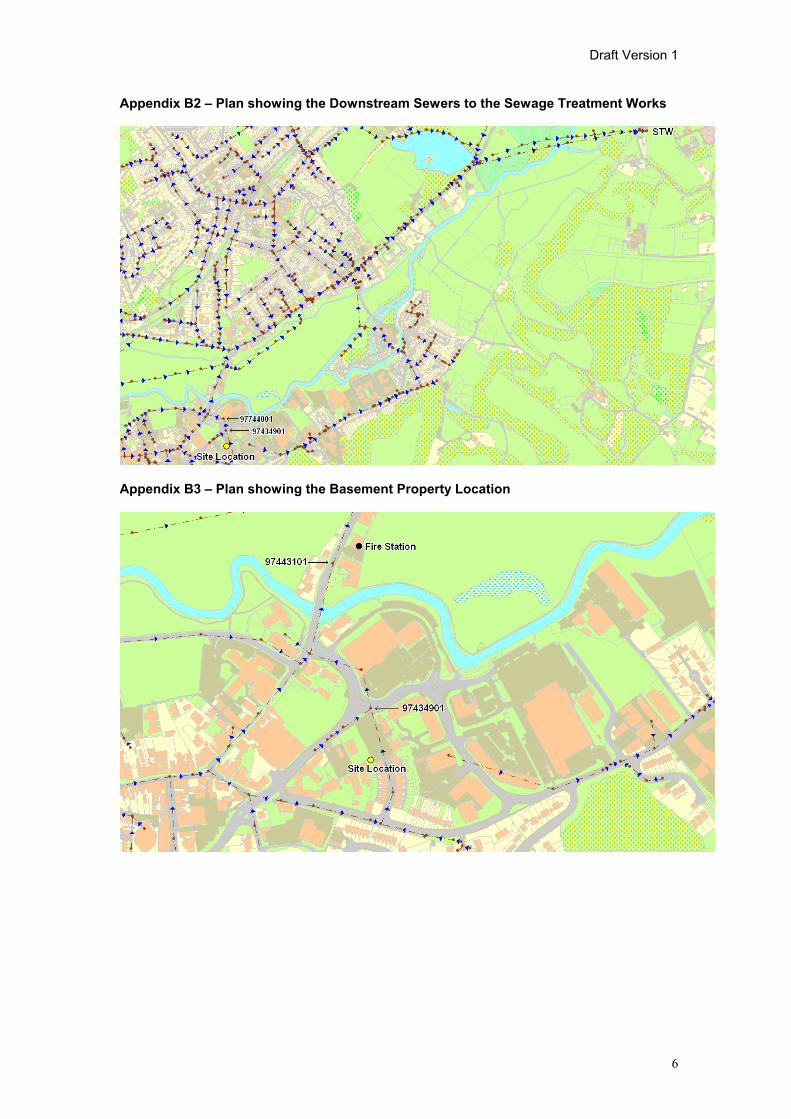
A plan showing the local sewers to the STW is provided in Appendix B2.
Assessment of Catchment with the Development Included
An allowance of 10.5 l/s based on the Sewers for Adoption (6th edition) figure of 4,000 l/property/day was used to assess the development impact as a 60 minute constant inflow into manhole SU97434901.
With development flows, the peak flow downstream of manhole SU97434901 increases to 16.3 l/s, and is within the calculated pipe full capacity of 42 L/s. The development does not cause any surcharging or flooding at the location of the connection point.
There is no new flooding predicted downstream of the development site. Surcharge values were increased only marginally with all surcharged conduits downstream of the development site reporting a freeboard greater than 0.5 m below ground level.
There is one basement location that can be hydraulically linked to the development site. The top water level at manhole SU97443101 decreases marginally from 2 m

Draft Version 1
4
below ground level in the existing scenario to 1.9 m below ground level once the development is included. All other locations downstream of the development that are located close to basements have top water levels more than 2 m below ground level. A plan showing the basement property is provided in Appendix B3.
6.0 Conclusions
There is capacity for the proposed 10.5 l/s development flow connecting into the local sewer at manhole SU97434901, based on the hydraulic assessment using the verified Godalming Infoworks model.
The above are recommendations to Thames Water Utilities, Developer Services Waste and may be altered or added to, based upon local operational knowledge of the system.

Draft Version 1
5
Appendix A - Site Plan
Appendix B - Plans showing the Site Location and the Local Sewers
Appendix B1 - Plan showing Site Location and Connection Point
Draft Version 1
6
Appendix B2 – Plan showing the Downstream Sewers to the Sewage Treatment Works
Appendix B3 – Plan showing the Basement Property Location

Flambard Developments Ltd
© Enzygo Ltd 2009 25 SHF.117.001
APPENDIX 5
Surface Water Management Strategy
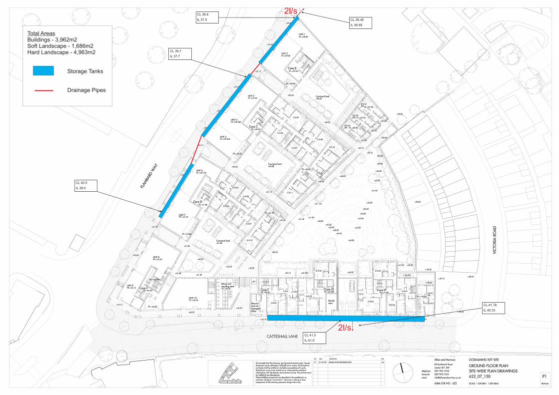
Total AreasBuildings - 3,962m2Soft Landscape - 1,686m2Hard Landscape - 4,963m2
Storage Tanks
Drainage Pipes
CL 41.5
IL 41.0
CL 40.5
IL 38.0
CL 39.7
IL 37.7
CL 38.6
IL 37.0 CL 38.48
IL 36.68
CL 41.78
IL 40.33
2l/s
2l/s