Table of Contents - electro-nc.com
63
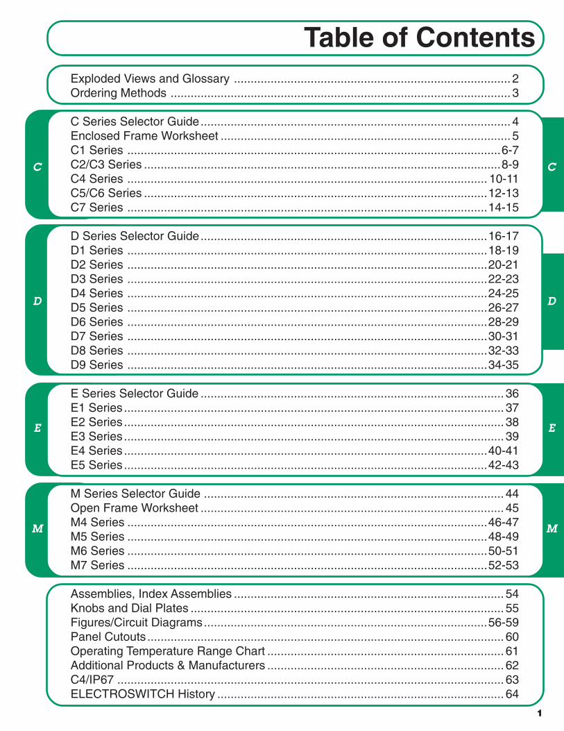
C D M 1 Table of Contents C D M E E Exploded Views and Glossary ................................................................................... 2 Ordering Methods ...................................................................................................... 3 C Series Selector Guide ............................................................................................. 4 Enclosed Frame Worksheet ....................................................................................... 5 C1 Series ................................................................................................................ 6-7 C2/C3 Series ........................................................................................................... 8-9 C4 Series ............................................................................................................ 10-11 C5/C6 Series ....................................................................................................... 12-13 C7 Series ............................................................................................................ 14-15 D Series Selector Guide ...................................................................................... 16-17 D1 Series ............................................................................................................ 18-19 D2 Series ............................................................................................................ 20-21 D3 Series ............................................................................................................ 22-23 D4 Series ............................................................................................................ 24-25 D5 Series ............................................................................................................ 26-27 D6 Series ............................................................................................................ 28-29 D7 Series ............................................................................................................ 30-31 D8 Series ............................................................................................................ 32-33 D9 Series ............................................................................................................ 34-35 E Series Selector Guide ........................................................................................... 36 E1 Series .................................................................................................................. 37 E2 Series .................................................................................................................. 38 E3 Series .................................................................................................................. 39 E4 Series ............................................................................................................. 40-41 E5 Series ............................................................................................................. 42-43 M Series Selector Guide .......................................................................................... 44 Open Frame Worksheet ........................................................................................... 45 M4 Series ............................................................................................................ 46-47 M5 Series ............................................................................................................ 48-49 M6 Series ............................................................................................................ 50-51 M7 Series ............................................................................................................ 52-53 Assemblies, Index Assemblies ................................................................................. 54 Knobs and Dial Plates .............................................................................................. 55 Figures/Circuit Diagrams ..................................................................................... 56-59 Panel Cutouts ........................................................................................................... 60 Operating Temperature Range Chart ....................................................................... 61 Additional Products & Manufacturers ....................................................................... 62 C4/IP67 .................................................................................................................... 63 ELECTROSWITCH History ...................................................................................... 64
Transcript of Table of Contents - electro-nc.com
C
D
M
1
Table of Contents
C
D
M
EE
Exploded Views and Glossary ................................................................................... 2Ordering Methods ...................................................................................................... 3
C Series Selector Guide............................................................................................. 4Enclosed Frame Worksheet ....................................................................................... 5C1 Series ................................................................................................................6-7C2/C3 Series ...........................................................................................................8-9C4 Series ............................................................................................................ 10-11C5/C6 Series .......................................................................................................12-13C7 Series ............................................................................................................14-15
D Series Selector Guide......................................................................................16-17D1 Series ............................................................................................................18-19D2 Series ............................................................................................................20-21D3 Series ............................................................................................................22-23D4 Series ............................................................................................................24-25D5 Series ............................................................................................................26-27D6 Series ............................................................................................................28-29D7 Series ............................................................................................................30-31D8 Series ............................................................................................................32-33D9 Series ............................................................................................................34-35
E Series Selector Guide ........................................................................................... 36E1 Series.................................................................................................................. 37E2 Series.................................................................................................................. 38E3 Series.................................................................................................................. 39E4 Series.............................................................................................................40-41E5 Series.............................................................................................................42-43
M Series Selector Guide .......................................................................................... 44Open Frame Worksheet ........................................................................................... 45M4 Series ............................................................................................................46-47M5 Series ............................................................................................................48-49M6 Series ............................................................................................................50-51M7 Series ............................................................................................................52-53
Assemblies, Index Assemblies ................................................................................. 54Knobs and Dial Plates .............................................................................................. 55Figures/Circuit Diagrams.....................................................................................56-59Panel Cutouts........................................................................................................... 60Operating Temperature Range Chart ....................................................................... 61Additional Products & Manufacturers ....................................................................... 62C4/IP67 .................................................................................................................... 63ELECTROSWITCH History ...................................................................................... 64

EXPLODED VIEWS AND GLOSSARY
EXAMPLE OF OPEN FRAME CONSTRUCTION
2UNIT OF ELECTRO SWITCH CORP.
• ELECTRONIC PRODUCTS2010 Yonkers RoadRaleigh, NC 27604
Telephone: (888) ROTARYS or (919) 833-0707Fax: (800) 909-9171 or (919) 833-8016
GLOSSARY
Ceramic - Used for stators, an inorganic, non-metallic material processed at high temperatures.Contact Resistance - The interface resistance between a clip and contact or a wiper and a contact.Diallyl Phthalate - Used for stators and modules, a thermosetting plastic.Dielectric Strength - The maximum voltage a section or deck assembly can handle.Glass Epoxy - Used for stators, a fiberglass material.Index and Detent Assembly - Performs the mechanical functions of the switch.Index Angle - The number of degrees between positions.Insulation Resistance - The resistance of the stator or module between switching components on the stator or module.Non-Shorting - Also known as break before make.Pole - An electrically isolated switching circuit. (Common).Polyester - Used for modules and switch bodies - a thermosetting or thermoplastic resin.Positions - The mechanical indexing of the electrical circuits. (Throw).Section and Module Assembly - Performs the electrical functions of the switch.Shorting - Also known as make before break.Stop Strength - The maximum rotation force the mechanical stop can facilitate.
StrutLockwasherStrutNut
Contact Clips
Rotor Stator
Spacers
MountingBushing Locating Lug
Plate
FrontPlate Index SpringsShaft
Section Assembly
Index Assembly
Index Wheel
MountingLockwasher
C-Ring
Strut Screws
Index Balls
Mounting NutAdjustableStopwasher
EXAMPLE OF ENCLOSED FRAME CONSTRUCTION
Wipers Detent Assembly
MountingLockwasher
Modules
Rotor
Shaft
DetentPlate
BallPressure
Plate
DetentSpring
StrutRivets
MountingBushing Mounting
Nut
AdjustableStopwasher
C-RingFrontHousing
DetentBalls
Rear Plate
Deck Assembly
(D2 SERIES SHOWN)
(C4 SERIES SHOWN)

3
ORDERING METHODS
Determine the most applicable switch construction (C) enclosed, (D) open frame, (E) specialpurpose or (M) military, and then use the appropriate selector guide to determine the desiredseries. There are four ways to select a switch from the catalog.
UNIT OF ELECTRO SWITCH CORP.
• ELECTRONIC PRODUCTS2010 Yonkers RoadRaleigh, NC 27604
Telephone: (888) ROTARYS or (919) 833-0707Fax: (800) 909-9171 or (919) 833-8016
■ 1. Use the pre-designed standard part numbers printed in the catalog.D4G0112S
Example:Contact typeNumber of positionsPoles per switchInsulation typeSeries designator
D 4 G 0 1 1 2 S
■ 2. Use the “How to Order Additional Options” section located with each series to specify theswitch requirements with standard options.
Example: D4G0902SSpecify additional pole and position options not listedin our standard part numbering section
■ 3. Use the “How to Order Additional Options” to add additional options to either a standardpart number or a standard option part number.
Example: D4G0902S –
■ 4. Contact the factory or your local representative of Electroswitch. Electroswitch designsand manufactures thousands of custom rotary switches, including “high volume one of a kind”designs. Open and enclosed frame worksheets are provided on pages 5 and 45 to helpcommunicate your requirements.
Example: D4G0902S- Factory Assigned
R 3 6 F 0 1 Z OptionsShaft flat angleShaft & bushing lengthsFixed stopsIndex angleRear PC Mount

C
4
CHARACTERISTICS SERIES C1 SERIES C2 SERIES C3 SERIES C4 SERIES C5 / C6 SERIES C7
Page Number 6,7 8,9 8,9 10,11 12,13 14,15
Construction ENCLOSED ENCLOSED ENCLOSED ENCLOSED ENCLOSED ENCLOSED
Diameter .865" wide .82" wide 1.20" wide 1.50" .92" 2.032"
Positions 2 - 12 2 - 8 2 - 12 2 - 12 2 - 12 2 - 24
E Current and Voltage 0.1A @ 125 VAC 0.1A @ 125 VAC 0.1A @ 125 VAC 0.3A @ 125 VAC 1.0A @ 125 VAC 0.5A @ 125 VAC
L 0.25A @ 28 VDC 0.25A @ 28 VDC 0.25A @ 28 VDC 0.5A @ 28 VDC 1.0A @ 28 VDC 1.0A @ 28 VDC
E Current Carrying Capacity 6A 6A 6A 15A 5A 25A
C Dielectric Strength 600 VAC 1,000 VAC 1,000 VAC 1,000 VAC 1,000 VAC 1,000 VAC
T Insulation Resistance 10,000 10,000 10,000 10,000 10,000 10,000
R (megohms)
I Contact Resistance 5 30 30 3 20 3
C (milliohms)
A
L
M Insulation - Glass Epoxy NO NO NO YES ★ NO NO
A Diallyl Phthalate STANDARD NO NO STANDARD NO STANDARD
T Ceramic NO NO NO NO NO NO
E Polyester NO STANDARD STANDARD NO STANDARD NO
R
I Contacts - Silver Alloy ★ YES NO NO YES NO YES
A Brass/Silver Plate STANDARD STANDARD STANDARD STANDARD STANDARD STANDARD
L
M Stop Strength 8 in. lb. 8 in. lb. 8 in. lb. 25 in. lb. 4.5 in. lb. 25 in. lb.
E Mechanical Life 25,000 cycles 25,000 cycles 25,000 cycles 25,000 cycles 10,000 cycles 25,000 cycles
C Detenting Angles: 15° — — — — — 15
H
A 30° 30 30 30 30 30 30
N 36° — — — 36 — —
I 45° — — — 45 — —
C 60° 60 60 60 60 — 60
A 90° 90 90 90 90 — 90
L
O Quick Connect NO NO NO YES NO YES
P Rear PC Mount YES NO NO YES YES NO
T Vertical PC Mount ★ YES YES YES YES NO NO
I Front PC Mount ★ NO NO NO YES NO NO
O Dual Concentric Designs ★ YES YES YES YES NO YES
N Keylock ★ YES YES YES YES NO YES
S Spring Return ★ NO NO NO YES NO NO
Water Resistant Seals ★ YES YES YES YES YES YES
★ Contact factory
SELECTOR GUIDE ENCLOSED ROTARY ELECTRONIC SWITCHES
UNIT OF ELECTRO SWITCH CORP.
• ELECTRONIC PRODUCTS2010 Yonkers RoadRaleigh, NC 27604
Telephone: (888) ROTARYS or (919) 833-0707Fax: (800) 909-9171 or (919) 833-8016
5
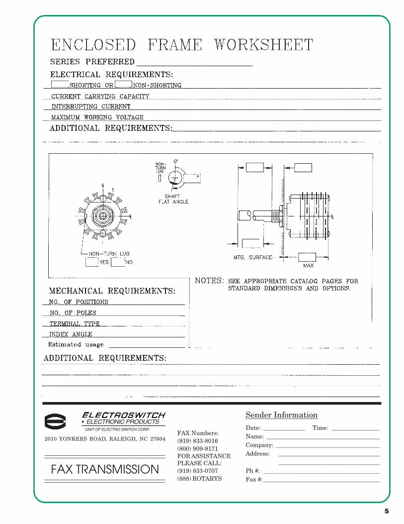
• ELECTRONIC PRODUCTSUNIT OF ELECTRO SWITCH CORP.
FAX Numbers:(919) 833-8016(800) 909-9171FOR ASSISTANCEPLEASE CALL:(919) 833-0707(888) ROTARYS
2010 YONKERS ROAD, RALEIGH, NC 27604
FAX TRANSMISSION
Sender Information
Date: ______________ Time: ________________Name: ______________________________________Company: ___________________________________Address: __________________________________
__________________________________Ph #: _______________________________________Fax #:_______________________________________

C SPECIFICATIONS
ELECTRICAL
Current and Voltage Rating: Make and break resistive load0.25 amp @ 28 VDC; 0.1 amp @ 125 VAC.Current Carrying Capacity: 6 amps.Dielectric Strength: 600 VAC between current carrying parts andground.Contact Resistance: Average initial 5 milliohms.Insulation Resistance: In excess of 10,000 megohms.
Hardware: Mounting nut and lockwasher are shipped assembled.
SOLDER LUG - ADJUSTABLE STOPSSWITCHES - 30° INDEXING - STOPS SET @ 2 POS.
VERTICAL P.C. TERMINALS - ADJUSTABLE STOPSSWITCHES - 30° INDEXING - STOPS SET @ 2 POS.
SPECIFICATIONS AND ORDERING INFORMATION
MECHANICAL
Materials and Finishes: All parts utilize non-corrosive materialsas standard.Terminals and Contacts: Brass with silver plate as standard.Insulation: Diallyl phthalate.Index: Dual-ball, hill and valley.Index Life: 25,000 cycles minimum.Index Torque: Switches have lowest practical torque consistentwith crisp detenting and smooth, reliable operation.Index Angles: 30° standard, 60°, and 90° available.Index Stops: Fixed standard, adjustable, or continuous available.Stop Strength: 8 in. lbs. minimum.
STANDARD PART NUMBER
DIMENSIONS
* FIGURES ARE SHOWN ON PAGE 55.
C1D C1D
SOLDER LUG CONSTRUCTION V VERTICAL P.C. CONSTRUCTION
6UNIT OF ELECTRO SWITCH CORP.
• ELECTRONIC PRODUCTS2010 Yonkers RoadRaleigh, NC 27604
Telephone: (888) ROTARYS or (919) 833-0707Fax: (800) 909-9171 or (919) 833-8016
C1 - SERIES0.865" WIDE 0.25 AMP @ 28 VDC
ACTIVE POLES/ NO. OF SHORTING NON- FIG.POLES POSITIONS DECK DECKS SHORTING *
ACTIVE POLES/ NO. OF SHORTING NON- FIG.POLES POSITIONS DECK DECKS SHORTING *
The C1 Series is our smallest enclosed rotary switch, offering index angles of30°, 60°, and 90°. Standard designs utilize solder lug or vertical PCterminals and diallyl phthalate insulation.
NOTE:1. ADD .200 FOR EACH ADDITIONAL DECK.2. 12 FIXED POSITION USES ADJUSTABLE STOP DIMENSIONS.
01 02-12 1 1 C1D0112S - A C1D0112N - A CA 01 02-06 1 1 C1D0106S - VA C1D0106N - VA CB02 02-12 1 2 C1D0212S - A C1D0212N - A CA 01 02-12 1 1 C1D0112S - VA C1D0112N - VA CC02 02-06 2 1 C1D0206S - A C1D0206N - A CH 02 02-06 1 2 C1D0206S - VA C1D0206N - VA CB03 02-12 1 3 C1D0312S - A C1D0312N - A CA 02 02-12 1 2 C1D0212S - VA C1D0212N - VA CC03 02-04 3 1 C1D0304S - A C1D0304N - A CK 03 02-06 1 3 C1D0306S - VA C1D0306N - VA CB04 02-06 2 2 C1D0406S - A C1D0406N - A CH 03 02-12 1 3 C1D0312S - VA C1D0312N - VA CC06 02-04 3 2 C1D0604S - A C1D0604N - A CK 04 02-06 1 4 C1D0406S - VA C1D0406N - VA CB06 02-06 2 3 C1D0606S - A C1D0606N - A CH 04 02-12 1 4 C1D0412S - VA C1D0412N - VA CC

C
C 1 DCUSTOMERS SPECIFIED ORDER NUMBER FOR STANDARD OPTIONS
(SPECIFY) (SPECIFY) (SPECIFY) (SPECIFY) (SPECIFY) (SPECIFY) (SPECIFY) (SPECIFY)
ADDITIONAL OPTIONS
UNIT OF ELECTRO SWITCH CORP.
• ELECTRONIC PRODUCTS2010 Yonkers RoadRaleigh, NC 27604
Telephone: (888) ROTARYS or (919) 833-0707Fax: (800) 909-9171 or (919) 833-8016
ADDITIONAL OPTIONS AND ORDERING INFORMATION C1 - SERIES
CUSTOM SWITCHES ARE AVAILABLE. CONTACT THE FACTORY WITH YOUR COMPLETE SPECIFICATIONS.
PRINTED CIRCUIT BOARD TERMINAL OPTIONS
SHAFT, BUSHING, AND FLAT OPTIONS
7
REAR P.C. FIXED STOP CONSTRUCTION P.C. BRD. PATTERN
SHAFT AS VIEWED WITH NON-TURNLUG AT 9 O'CLOCK AND SHAFT IN EX-TREME CCW POSITION AND STRUTBOLTS ORIENTED VERTICALLY.
STOP PINS
ADJUSTABLE STOPMECHANISM
R
2 DIGIT INSULATION TOTAL ACTIVE CONTACTSERIES TYPE POLES POSITIONS TYPE
TERMINAL INDEX STOP SHAFT/ SHAFTTYPE ANGLE TYPE BUSHING FLAT
C1 D - DIALLYL 01 - MIN. 12 - MAX @ 30° N - NON-06 - MAX @ 60° SHORTING04 - MAX @ 90° S - SHORTING
L - SOLDER LUG 30° F - FIXEDV - VERT. P.C. 60° C - CONT.
90° A - ADJ.SEE SEE
R - REAR P.C. 30° F - FIXED CHART CHART60° C - CONT. "A" "B"90°
How to Order Additional Options:
U
Y Z
W

195°
C SPECIFICATIONS
ELECTRICAL
Current and Voltage Rating: Make and break resistive load0.25 amp @ 28 VDC; 0.1 amp @ 125 VAC.Current Carrying Capacity: 6 amps.Dielectric Strength: 1,000 VAC between current carrying parts andground.Contact Resistance: Average initial 30 milliohms.Insulation Resistance: In excess of 10,000 megohms.
Hardware: Mounting nut and lockwasher are shipped assembled.
C2 - 8 PIN CONSTRUCTION SWITCHES - 30° INDEXINGADJUSTABLE STOPS SET @ 2 POS. - P.C. TERMINALS
C3 - 12 PIN CONSTRUCTION SWITCHES - 30° INDEXINGADJUSTABLE STOPS SET @ 2 POS. - P.C. TERMINALS
SPECIFICATIONS AND ORDERING INFORMATIONC2/C3 - SERIES0.82 / 1.2" WIDE 0.25 AMP @ 28 VDC
MECHANICAL
Materials and Finishes: All parts utilize non-corrosive materialsas standard.Terminals and Contacts: Brass with silver plate as standard.Insulation: Polyester.Index: Dual-ball, hill and valley.Index Life: 25,000 cycles minimum.Index Torque: Switches have lowest practical torque consistentwith crisp detenting and smooth, reliable operation.Index Angles: Positive 30° standard, 60°, and 90° available.Index Stops: Fixed standard, adjustable, or continuous available.Stop Strength: 8 in. lbs. minimum.
STANDARD PART NUMBER
C2 - DIMENSIONS - 8 PIN DESIGN
* FIGURES ARE SHOWN ON PAGE 55.
C2P - STANDARD 8–PIN PER DECK ARRANGEMENT
8UNIT OF ELECTRO SWITCH CORP.
• ELECTRONIC PRODUCTS2010 Yonkers RoadRaleigh, NC 27604
Telephone: (888) ROTARYS or (919) 833-0707Fax: (800) 909-9171 or (919) 833-8016
A
ACTIVE POLES/ NO. OF SHORTING NON- FIG.POLES POSITIONS DECK DECKS SHORTING *
ACTIVE POLES/ NO. OF SHORTING NON- FIG.POLES POSITIONS DECK DECKS SHORTING *
The C2/C3 Series offers an 8 position and a 12 position vertical P.C. boardmountable design. Standard designs utilize a 30° index angle and polyesterinsulation.
1/4" DIAMETER SHAFTS ARE AVAILABLE.CONTACT FACTORY.
01 02-08 1 1 C2P0108S - A C2P0108N - A CD 01 02-12 1 1 C3P0112S - A C3P0112N - A CA02 02-08 1 2 C2P0208S - A C2P0208N - A CD 02 02-12 1 2 C3P0212S - A C3P0212N - A CA02 02-04 2 1 C2P0204S - A C2P0204N - A CI 02 02-06 2 1 C3P0206S - A C3P0206N - A CH03 02-08 1 3 C2P0308S - A C2P0308N - A CD 03 02-04 3 1 C3P0304S - A C3P0304N - A CK04 02-04 2 2 C2P0404S - A C2P0404N - A CI 03 02-12 1 3 C3P0312S - A C3P0312N - A CA04 02-08 1 4 C2P0408S - A C2P0408N - A CD 04 02-06 2 2 C3P0406S - A C3P0406N - A CH05 02-08 1 5 C2P0508S - A C2P0508N - A CD 04 02-12 1 4 C3P0412S - A C3P0412N - A CA06 02-04 2 3 C2P0604S - A C2P0604N - A CI 06 02-04 3 2 C3P0604S - A C3P0604N - A CK

C
UNIT OF ELECTRO SWITCH CORP.
• ELECTRONIC PRODUCTS
ADDITIONAL OPTIONS ANDORDERING INFORMATION C2/C3 - SERIES
CUSTOM SWITCHES ARE AVAILABLE. CONTACT THE FACTORY WITH YOUR COMPLETE SPECIFICATIONS.
C3 - DIMENSIONS - 12 PIN DESIGN
C3P - STANDARD 12–PIN PER DECK ARRANGEMENT
SHAFT AND FLAT OPTIONS
9
SHAFT AS VIEWEDWITH NON-TURN LUGAT 9 O'CLOCK ANDSHAFT IN EXTREMECCW POSITION ANDSTRUT BOLTSORIENTED VERTICALLY.
2010 Yonkers RoadRaleigh, NC 27604
Telephone: (888) ROTARYS or (919) 833-0707Fax: (800) 909-9171 or (919) 833-8016
PRINTED CIRCUITBOARD PATTERN
C2 C38–PIN DECK 12–PIN DECK
CUSTOMERS SPECIFIED ORDER NUMBER FOR STANDARD OPTIONS
(SPECIFY) (SPECIFY) (SPECIFY) (SPECIFY) (SPECIFY) (SPECIFY) (SPECIFY)
ADDITIONAL OPTIONS
P
NOTE:1. ONE DECK EQUALS
TWO WAFERS.2. ADD .300" FOR EACH ADDITIONAL DECK.3. 12 FIXED POSITION USES ADJUSTABLE STOP DIMENSIONS.
1/4" DIAMETER SHAFTS ARE AVAILABLE.CONTACT FACTORY.
2 DIGIT INSULATION TOTAL ACTIVE CONTACTSERIES TYPE POLES POSITIONS TYPE
TERMINAL INDEX STOP SHAFT/ SHAFTTYPE ANGLE TYPE BUSHING FLAT
C2 P-POLYESTER 01 - MIN. 08 - MAX @ 30° N - NON04 - MAX @ 60° SHORTING03 - MAX @ 90° S - SHORTING
C3 P-POLYESTER 01 - MIN. 12 - MAX @ 30° N - NON06 - MAX @ 60° SHORTING04 - MAX @ 90° S - SHORTING
30° F - FIXED60° C - CONT.90° A - ADJ.
SEE SEECHART CHART
"A" "B"
How to Order Additional Options:
NOTES:1. The standard spacing for the 1/8” dia. shaft from the firstrow of terminals to the mounting surface is .390 in.2. The standard spacing for the 1/4” dia. shaft from the firstrow of terminals to the mounting surface is .481 in. U YW Z

C SPECIFICATIONS
ELECTRICALCurrent and Voltage Rating: Make and break resistive load0.5 amp @ 28 VDC; 0.3 amp @ 125 VAC.Current Carrying Capacity: 15 amps.Dielectric Strength: 1,000 VAC between current carrying parts andground.Contact Resistance: Average initial 3 milliohms.Insulation Resistance: In excess of 10,000 megohms.
Hardware: Mounting nut and lockwasher are shipped assembled.
SOLDER LUG - ADJUSTABLE STOPSSWITCHES - 30° INDEXING - STOPS SET @ 2 POS.
SPECIFICATIONS AND ORDERING INFORMATIONC4 - SERIES1.5" DIAMETER 0.5 AMP @ 28 VDC
MECHANICALMaterials and Finishes: All parts utilize non-corrosive materialsas standard.Terminals and Contacts: Brass with silver plate as standard.Insulation: Diallyl phthalate.Index: Dual-ball, hill and valley.Index Life: 25,000 cycles minimum.Index Torque: Switches have lowest practical torque consistentwith crisp detenting and smooth, reliable operation.Index Angles: 30° standard, 36°, 45°, 60°, and 90° available.Index Stops: Fixed standard, adjustable or continuous available.Stop Strength: 15 in. lbs. minimum.
STANDARD PART NUMBER
DIMENSIONS
* FIGURES ARE SHOWN ON PAGE 55.
C4D STANDARD CONSTRUCTION
10UNIT OF ELECTRO SWITCH CORP.
• ELECTRONIC PRODUCTS2010 Yonkers RoadRaleigh, NC 27604
Telephone: (888) ROTARYS or (919) 833-0707Fax: (800) 909-9171 or (919) 833-8016
The C4 Series provides a versatile, fully enclosed design, that helps keepdirt and moisture out of the contact area while locking in life time lubricants.IP67 Rating Available.
Q
ACTIVE POLES/ NO. OF SHORTING NON- FIG.POLES POSITIONS DECK DECKS SHORTING *
ACTIVE POLES/ NO. OF SHORTING NON- FIG.POLES POSITIONS DECK DECKS SHORTING *
01 02-12 1 1 C4D0112S - A C4D0112N - A CA 06 02-06 2 3 C4D0606S - A C4D0606N - A CH02 02-06 2 1 C4D0206S - A C4D0206N - A CH 06 02-04 3 2 C4D0604S - A C4D0604N - A CK02 02-12 1 2 C4D0212S - A C4D0212N - A CA 06 02-12 1 6 C4D0612S - A C4D0612N - A CA03 02-12 1 3 C4D0312S - A C4D0312N - A CA 08 02-06 2 4 C4D0806S - A C4D0806N - A CH03 02-04 3 1 C4D0304S - A C4D0304N - A CK 09 02-04 3 3 C4D0904S - A C4D0904N - A CK04 02-12 1 4 C4D0412S - A C4D0412N - A CA 10 02-06 2 5 C4D1006S - A C4D1006N - A CH04 02-06 2 2 C4D0406S - A C4D0406N - A CH 12 02-04 3 4 C4D1204S - A C4D1204N - A CK05 02-12 1 5 C4D0512S - A C4D0512N - A CA 15 02-04 3 5 C4D1504S - A C4D1504N - A CK

C
C 4 DCUSTOMERS SPECIFIED ORDER NUMBER FOR STANDARD OPTIONS
(SPECIFY) (SPECIFY) (SPECIFY) (SPECIFY) (SPECIFY) (SPECIFY) (SPECIFY) (SPECIFY)
ADDITIONAL OPTIONS
UNIT OF ELECTRO SWITCH CORP.
• ELECTRONIC PRODUCTS
ADDITIONAL OPTIONS AND ORDERING INFORMATION C4 - SERIES
CUSTOM SWITCHES ARE AVAILABLE. CONTACT THE FACTORY WITH YOUR COMPLETE SPECIFICATIONS.
PRINTED CIRCUIT BOARD TERMINAL OPTIONS
FRONT PRINTED CIRCUIT REAR PRINTED CIRCUIT
SHAFT, BUSHING, AND FLAT OPTIONS
11
2010 Yonkers RoadRaleigh, NC 27604
Telephone: (888) ROTARYS or (919) 833-0707Fax: (800) 909-9171 or (919) 833-8016
PRINTED CIRCUITBOARD HOLE PATTERNS
30° INDEX, 1 AND 2 POLE
36° INDEX, 10 POSITION
YW
PR
ZU
SHAFT AS VIEWEDWITH NON-TURN LUGAT 9 O'CLOCK ANDSHAFT IN EXTREMECCW POSITION ANDSTRUT BOLTSORIENTED VERTICALLY.
2 DIGIT INSULATION TOTAL ACTIVE CONTACTSERIES TYPE POLES POSITIONS TYPE
TERMINAL INDEX STOP SHAFT/ SHAFTTYPE ANGLE TYPE BUSHING FLAT
C4 D - DIALLYL 01 - MIN. 12 - MAX @ 30° S - SHORTING10 - MAX@ 36° N - NON08 - MAX @ 45° SHORTING06 - MAX @ 60°04 - MAX @ 90°
L - SOLDER LUG 30° F - FIXEDP - FRONT P.C. 36° A - A D J . (NOT IN 45°)
R - REAR P.C. 45° (30°,60°,90° (30° & 36° ONLY) 60° ONLY) SEE SEEQ - QUICK 90° C - CONT. CHART CHART
CONNECT "A" "B"
How to Order Additional Options:

C SPECIFICATIONS
ELECTRICAL
Current and Voltage Rating: Make and break resistive load1 amp @ 28 VDC; 1 amp @ 125 VAC.Current Carrying Capacity: 5 amps.Dielectric Strength: 1,000 VAC between current carrying parts andground.Contact Resistance: Average initial 20 milliohms.Insulation Resistance: In excess of 10,000 megohms.
Hardware: Mounting nut and lockwasher are shipped assembled.
C5 - SOLDER LUG TERMINALSSWITCHES - 30° INDEX - ADJUSTABLE STOPS - SET @ 2 POS. - SEALED
C5 - P.C. TERMINALSSWITCHES - 30° INDEX - ADJUSTABLE STOPS - SET @ 2 POS. - SEALED
C5/C6 - SERIES0.92" DIAMETER 1.0 AMP @ 28 VDC
The C5 Series offers a very economical and lightweight design. Standardfeatures include 30° indexing up to 12 positions, solder lug terminals, fixedstops, and both internal and external seals for washability.The C6 Series offers the same features in an unsealed design.
MECHANICAL
Materials and Finishes: All parts utilize non-corrosive materialsas standard.Terminals and Contacts: Brass with silver plate as standard.Insulation: Polyester.Index: Molded live spring detent.Index Life: 10,000 cycles minimum.Index Torque: Switches have lowest practical torque consistentwith crisp detenting and smooth, reliable operation.Index Angles: Positive 30° standard.Index Stops: Fixed standard, adjustable, or continuous available.Stop Strength: 4.5 in. lbs. minimum.
STANDARD PART NUMBER
DIMENSIONS
* FIGURES ARE SHOWN ON PAGE 55.
STANDARD CONSTRUCTION
12UNIT OF ELECTRO SWITCH CORP.
• ELECTRONIC PRODUCTS2010 Yonkers RoadRaleigh, NC 27604
Telephone: (888) ROTARYS or (919) 833-0707Fax: (800) 909-9171 or (919) 833-8016
SPECIFICATIONS AND ORDERING INFORMATION
ACTIVE POLES/ NO. OF NON- FIG.POLES POSITIONS SECTION SECTIONS SHORTING *
ACTIVE POLES/ NO. OF NON- FIG.POLES POSITIONS SECTION SECTIONS SHORTING *
01 02-12 1 1 C5P0112N - A CE 01 02-12 1 1 C5P0112N - RA CE02 02-06 2 1 C5P0206N - A CJ 02 02-06 2 1 C5P0206N - RA CJ03 02-04 3 1 C5P0304N - A CL 03 02-04 3 1 C5P0304N - RA CL04 02-03 4 1 C5P0403N - A CM 04 02-03 4 1 C5P0403N - RA CM
C6 - UNSEALED C6 - UNSEALED01 02-12 1 1 C6P0112N - A CE 01 02-12 1 1 C6P0112N - RA CE02 02-06 2 1 C6P0206N - A CJ 02 02-06 2 1 C6P0206N - RA CJ03 02-04 3 1 C6P0304N - A CL 03 02-04 3 1 C6P0304N - RA CL04 02-03 4 1 C6P0403N - A CM 04 02-03 4 1 C6P0403N - RA CM

C
PCUSTOMERS SPECIFIED ORDER NUMBER FOR STANDARD OPTIONS
(SPECIFY) (SPECIFY) (SPECIFY) (SPECIFY) (SPECIFY) (SPECIFY) (SPECIFY)
ADDITIONAL OPTIONS
UNIT OF ELECTRO SWITCH CORP.
• ELECTRONIC PRODUCTS2010 Yonkers RoadRaleigh, NC 27604
Telephone: (888) ROTARYS or (919) 833-0707Fax: (800) 909-9171 or (919) 833-8016
C5/C6 - SERIES
CUSTOM SWITCHES ARE AVAILABLE. CONTACT THE FACTORY WITH YOUR COMPLETE SPECIFICATIONS.
PRINTED CIRCUIT BOARD TERMINAL PATTERNS
SHAFT AND FLAT OPTIONS
13
1-POLE 2-POLE 3-POLE 4-POLE
SHAFT AS VIEWEDWITH NON-TURN LUGAT 9 O'CLOCK ANDSHAFT IN EXTREMECCW POSITION .
TERMINAL TYPES
N
ADDITIONAL OPTIONS ANDORDERING INFORMATION
2 DIGIT INSULATION TOTAL ACTIVE CONTACTSERIES TYPE POLES POSITIONS TYPE
TERMINAL INDEX STOP SHAFT/ SHAFTTYPE ANGLE TYPE BUSHING FLAT
C5 P - POLYESTER 01 12 - MAX N - NON -SEALED 02 06 - MAX SHORTING
03 04 - MAX04 03 - MAX
C6 P - POLYESTER 01 12 - MAX N - NON -UNSEALED 02 06 - MAX SHORTING
03 04 - MAX04 03 - MAX
L - SOLDER LUG F - FIXEDR - REAR P.C. A - ADJ.
C - CONT.
SEE SEECHART CHART
"A" "B"
How to Order Additional Options:
R
L
1
1
11
11
1
1
1
1 = 1ST POSITION
Y
14 1 1/215 SLOTTED
1

C SPECIFICATIONS
ELECTRICAL
Current and Voltage Rating: Make and break resistive load1.0 amp @ 28 VDC; 0.5 amp @ 125 VAC.Current Carrying Capacity: 25 amps.Dielectric Strength: 1,000 VAC between current carrying parts andground.Contact Resistance: Average initial 3 milliohms.Insulation Resistance: In excess of 10,000 megohms.
Hardware: Mounting nut and lockwasher are shipped assembled.
15° INDEXING - FIXED STOPSSOLDER LUG TERMINALS
15° INDEXING - CONTINUOUS ROTATIONSOLDER LUG TERMINALS
SPECIFICATIONS AND ORDERING INFORMATIONC7 - SERIES2 1/32" DIAMETER 1.0 AMP @ 28 VDC
The C7 Series provides a fully enclosed, modular design that enablesswitching up to 24 positions. Our standard design offers 15° indexing,and solder lug terminals.
MECHANICAL
Materials and Finishes: All parts utilize non-corrosive materialsas standard.Terminals and Contacts: Brass with silver plate as standard.Insulation: Diallyl phthalate.Index: Single-ball, hill and valley.Index Life: 25,000 cycles minimum.Index Torque: Switches have lowest practical torque consistentwith crisp detenting and smooth, reliable operation.Index Angles: 15° standard, 30°, 60°, and 90° available.Index Stops: Fixed standard, continuous, or adj. available.Stop Strength: 25 in. lbs. minimum.
STANDARD PART NUMBER
DIMENSIONS
* FIGURES ARE SHOWN ON PAGE 55.
STANDARD CONSTRUCTION - 15° INDEX ANGLE (3 WAFER DECK) .187 QUICK CONNECT
14UNIT OF ELECTRO SWITCH CORP.
• ELECTRONIC PRODUCTS2010 Yonkers RoadRaleigh, NC 27604
Telephone: (888) ROTARYS or (919) 833-0707Fax: (800) 909-9171 or (919) 833-8016
ACTIVE POLES/ NO. OF SHORTING NON- FIG.POLES POSITIONS DECK DECKS SHORTING *
ACTIVE POLES/ NO. OF SHORTING NON- FIG.POLES POSITIONS DECK DECKS SHORTING *
Q
01 23 1 1 C7D0123S C7D0123N CF 01 24 1 1 C7D0124S - C C7D0124N - C CG02 23 1 2 C7D0223S C7D0223N CF 02 24 1 2 C7D0224S - C C7D0224N - C CG03 23 1 3 C7D0323S C7D0323N CF 03 24 1 3 C7D0324S - C C7D0324N - C CG04 23 1 4 C7D0423S C7D0423N CF 04 24 1 4 C7D0424S - C C7D0424N - C CG
30° INDEXING 30° INDEXING01 12 1 1 C7D0112S -30 C7D0112N -30 CA 01 12 1 1 C7D0112S -30C C7D0112N -30C CA02 12 1 2 C7D0212S -30 C7D0212N -30 CA 02 12 1 2 C7D0212S -30C C7D0212N -30C CA03 12 1 3 C7D0312S -30 C7D0312N -30 CA 03 12 1 3 C7D0312S -30C C7D0312N -30C CA

C
U YW Z
C 7 DCUSTOMERS SPECIFIED ORDER NUMBER FOR STANDARD OPTIONS
(SPECIFY) (SPECIFY) (SPECIFY) (SPECIFY) (SPECIFY) (SPECIFY) (SPECIFY) (SPECIFY)
ADDITIONAL OPTIONS
UNIT OF ELECTRO SWITCH CORP.
• ELECTRONIC PRODUCTS2010 Yonkers RoadRaleigh, NC 27604
Telephone: (888) ROTARYS or (919) 833-0707Fax: (800) 909-9171 or (919) 833-8016
ADDITIONAL OPTIONS AND ORDERING INFORMATION C7 - SERIES
CUSTOM SWITCHES ARE AVAILABLE. CONTACT THE FACTORY WITH YOUR COMPLETE SPECIFICATIONS.
DIMENSIONS
15
STANDARD CONSTRUCTION - 30° INDEX ANGLE (2 WAFER DECK)
SHAFT AND FLAT OPTIONS
SHAFT AS VIEWEDWITH NON-TURN LUGAT 9 O'CLOCK ANDSHAFT IN EXTREMECCW POSITION .
SHORTING ANDNON-SHORTINGSWITCHING IS
NOT GUARANTEEDON THE 15° INDEXING
C7 SERIES.
2 DIGIT INSULATION TOTAL ACTIVE CONTACTSERIES TYPE POLES POSITIONS TYPE
TERMINAL INDEX STOP SHAFT/ SHAFTTYPE ANGLE TYPE BUSHING FLAT
C7 D - DIALLYL 01 - MIN. 24 - MAX @ 15° S - SHORTINGN - NON
SHORTING
C7 D - DIALLYL 01 - MIN. 12 - MAX @ 30° S - SHORTING06 - MAX @ 60° N - NON04 - MAX @ 90° SHORTING
L - SOLDER LUG 15° F - FIXEDQ - QUICK 23 - POS. MAX.
CONNECT C - CONT. 24 - POS. MAX. SEE SEE
CHART CHARTL - SOLDER LUG30° A23 - POS. MAX. "A" "B"Q - QUICK 60° C - CONT.
CONNECT 90° a - Adjustable
How to Order Additional Options:
A- Adjustable

SELECTOR GUIDE OPEN FRAME ROTARY ELECTRONIC SWITCHES
CHARACTERISTICS SERIES D1 SERIES D2 SERIES D3 SERIES D4 SERIES D5 SERIES D6
Page Number 18,19 20,21 22,23 24,25 26,27 28,29
Construction OPEN OPEN OPEN OPEN OPEN OPEN
Diameter 1.00" 1.00" 1.312" 1.437" 1.437" 1.687"
Positions 2 - 12 2 - 12 2 - 12 2 - 12 2 - 12 2 - 12
E Current and Voltage 0.25A @ 115 VAC 0.25A @ 115 VAC 0.5A @ 115 VAC 0.5A @ 115 VAC 0.5A @ 115 VAC 0.5A @ 115 VAC
L 0.55A @ 28 VDC 0.55A @ 28 VDC 1.5A @ 28 VDC 1.5A @ 28 VDC 1.5A @ 28 VDC 1.5A @ 28 VDC
E Current Carrying Capacity 7A 7A 12A 9A 9A 9A
C Dielectric Strength 750 VAC 750 VAC 1,000 VAC 1,500 VAC 1,500 VAC 1,500 VAC
T Insulation Resistance 750,000 900,000 1,000,000 1,000,000 750,000 900,000
R (megohms)
I Contact Resistance 5 5 3.5 3.5 3.5 3.5
C (milliohms)
A
L
M Insulation - Glass Epoxy STANDARD YES STANDARD STANDARD STANDARD YES
A Diallyl Phthalate YES STANDARD YES YES NO STANDARD
T Ceramic YES YES YES YES NO YES
E
R
I Contacts - Silver Alloy ★ YES YES STD-CERAMIC YES YES YES
A Brass/Silver Plate STANDARD STANDARD STD-GLASS STANDARD STANDARD STANDARD
L
M Stop Strength 10 in. lb. 10 in. lb. 25 in. lb. 10 in. lb. 25 in. lb. 25 in. lb.
E Mechanical Life 25,000 cycles 25,000 cycles 25,000 cycles 25,000 cycles 25,000 cycles 25,000 cycles
C Detenting Angles:
H
A 30° 30 30 30 30 30 30
N 36° 36 36 — — — 36
I 45° 45 45 — — — 45
C 60° — 60 60 60 — 60
A
L
O Quick Connect NO NO NO NO NO NO
P Rear PC Mount YES YES YES YES YES YES
T Vertical PC Mount ★ YES YES NO NO NO NO
I Front PC Mount ★ YES YES YES YES YES YES
O Dual Concentric Designs ★ YES YES YES YES NO NO
N Keylock ★ YES YES YES YES YES YES
S Spring Return ★ NO NO NO NO NO NO
Water Resistant Seals ★ YES YES YES YES YES YES
Originally Designed To SR05 N/A SR03 SR02 N/A N/AMeet Mil 3786/
★ Contact factory
16UNIT OF ELECTRO SWITCH CORP.
• ELECTRONIC PRODUCTS2010 Yonkers RoadRaleigh, NC 27604
Telephone: (888) ROTARYS or (919) 833-0707Fax: (800) 909-9171 or (919) 833-8016
D

D
SELECTOR GUIDE OPEN FRAME ROTARY ELECTRONIC SWITCHES
CHARACTERISTICS SERIES D7 SERIES D8 SERIES D9
Page Number 30,31 32,33 34,35
Construction OPEN OPEN OPEN
Diameter 1.875" 2.312" 2.312"
Positions 2 - 12 2 - 18 2 - 24
E Current and Voltage 1.0A @ 115 VAC 1.0A @ 115 VAC 0.25A @ 115 VAC
L 2.25A @ 28 VDC 2.25A @ 28 VDC 1.5A @ 28 VDC
E Current Carrying Capacity 9A 9A 9A
C Dielectric Strength 1,500 VAC 1,000 VAC 1,000 VAC
T Insulation Resistance 750 ,000 750,000 750 ,000
R (megohms)
I Contact Resistance 3.5 5 5
C (milliohms)
A
L
M Insulation - Glass Epoxy STANDARD STANDARD STANDARD
A Diallyl Phthalate NO NO NO
T Ceramic YES NO NO
E
R
I Contacts - Silver Alloy ★ YES YES YES
A Brass/Silver Plate STANDARD STANDARD STANDARD
L
M Stop Strength 25 in. lb. 25 in. lb. 25 in. lb.
E Mechanical Life 25,000 cycles 25,000 cycles 25,000 cycles
C Detenting Angles: 15° — — 15
H 20° — 20 —
A 22.5° — — —
N 30° 30 — —
I 36° — — —
C 45° — — —
A 60° 60 — —
L
O Quick Connect NO NO NO
P Rear PC Mount NO NO YES
T Vertical PC Mount ★ NO NO NO
I Front PC Mount ★ NO NO NO
O Dual Concentric Designs ★ YES YES YES
N Keylock ★ YES YES YES
S Spring Return ★ NO NO NO
Water Resistant Seals ★ YES YES YES
Originally Designed To N/A N/A N/AMeet Mil 3786/
★ Contact factory
UNIT OF ELECTRO SWITCH CORP.
• ELECTRONIC PRODUCTS2010 Yonkers RoadRaleigh, NC 27604
Telephone: (888) ROTARYS or (919) 833-0707Fax: (800) 909-9171 or (919) 833-8016 17
Also see our “E” Seriessection for specialty openframe switches on pages 37thru 43.
Use the open frameworksheet on page 45 forcustom designs.

D
SPECIFICATIONS
ELECTRICAL
Current and Voltage Rating: Make and break resistive load0.55 amp @ 28 VDC; 0.25 amp @ 115 VAC.Current Carrying Capacity: 7 amps.Dielectric Strength: 750 VAC between current carrying parts andground.Contact Resistance: Average initial 5 milliohms.Insulation Resistance: Diallyl in excess of 900,000 megohms.
Glass in excess of 750,000 megohms.Ceramic in excess of 1,000,000 megohms.
Hardware: Mounting nut and lockwasher are shipped assembled.
SPECIFICATIONS AND ORDERING INFORMATIOND1 - SERIES1" DIAMETER 0.55 AMP @ 28 VDC
MECHANICAL
Materials and Finishes: All parts utilize non-corrosive materialsas standard.Clips and Rotors: Brass with silver plate as standard.Insulation: Glass, diallyl phthalate, or ceramic.Index: Dual-ball, side thrust design.Index Life: 25,000 cycles minimum.Index Torque: Switches have lowest practical torque consistentwith crisp detenting and smooth, reliable operation.Index Angle: Positive 30° standard, 36°, and 45° available.Index Stops: Fixed or Continuous available.Stop Strength: 10 in. lbs. minimum.
STANDARD PART NO.
DIMENSIONS
* FIGURES ARE SHOWN ON PAGES 55 AND 56.
STANDARD CONSTRUCTION D1G - STANDARD GLASS D1CEPOXY CONSTRUCTION CERAMIC INSULATION
18UNIT OF ELECTRO SWITCH CORP.
• ELECTRONIC PRODUCTS2010 Yonkers RoadRaleigh, NC 27604
Telephone: (888) ROTARYS or (919) 833-0707Fax: (800) 909-9171 or (919) 833-8016
ACTIVE POLES/ NO. OF SHORTING NON- FIG.POLES POSITIONS SECTION SECTIONS SHORTING *
ACTIVE POLES/ NO. OF SHORTING NON- FIG.POLES POSITIONS SECTION SECTIONS SHORTING *
EPOXY GLASS INSULATIONSWITCHES - SOLDER LUG TERMINALS - 30° INDEX
CERAMIC INSULATIONSWITCHES - SOLDER LUG TERMINALS - 30° INDEX
This 1" diameter switch offers a unique lateral thrust index with exceptionallycrisp torque. The D1 Series was originally designed to meet the size require-ments of MIL-S-3786 style SR05. The 30° index and glass epoxy insulationare standard and several options are available including rear printed circuitterminals.
01 02-12 1 1 D1G0112S-F D1G0112N-F DE 01 02-11 1 1 D1C0111S-F D1C0111N-F DB02 02-12 1 2 D1G0212S-F D1G0212N-F DE 02 02-11 1 2 D1C0211S-F D1C0211N-F DB02 02-06 2 1 D1G0206S-F D1G0206N-F DL 02 02-05 2 1 D1C0205S-F D1C0205N-F DG03 02-12 1 3 D1G0312S-F D1G0312N-F DE 03 02-11 1 3 D1C0311S-F D1C0311N-F DB03 02-05 3 1 D1G0305S-F D1G0305N-F DO 03 02-03 3 1 D1C0303S-F D1C0303N-F DN04 02-06 2 2 D1G0406S-F D1G0406N-F DL 04 02-05 2 2 D1C0405S-F D1C0405N-F DG06 02-06 2 3 D1G0606S-F D1G0606N-F DL 06 02-05 2 3 D1C0605S-F D1C0605N-F DG06 02-05 3 2 D1G0605S-F D1G0605N-F DO 06 02-03 3 2 D1C0603S-F D1C0603N-F DN
3/8

D
U YW Z
SHAFT, BUSHING, AND FLAT OPTIONS
SHAFT AS VIEWEDWITH NON-TURN LUGAT 9 O'CLOCK ANDSHAFT IN EXTREMECCW POSITION ANDSTRUT BOLTSORIENTED VERTICALLY.
ADDITIONAL OPTIONS AND ORDERING INFORMATION D1 - SERIES
CUSTOM SWITCHES ARE AVAILABLE. CONTACT THE FACTORY WITH YOUR COMPLETE SPECIFICATIONS.
INSULATION AND PRINTED CIRCUIT BOARD TERMINAL OPTIONS
D1D REAR PRINTED PC BOARDDIALLYL PHTHALATE INSULATION CIRCUIT TERMINALS MOUNTING PATTERN
D 1CUSTOMERS SPECIFIED ORDER NUMBER FOR STANDARD OPTIONS
(SPECIFY) (SPECIFY) (SPECIFY) (SPECIFY) (SPECIFY) (SPECIFY) (SPECIFY) (SPECIFY)
ADDITIONAL OPTIONS
UNIT OF ELECTRO SWITCH CORP.
• ELECTRONIC PRODUCTS2010 Yonkers RoadRaleigh, NC 27604
Telephone: (888) ROTARYS or (919) 833-0707Fax: (800) 909-9171 or (919) 833-8016 19
R
2 DIGIT INSULATION TOTAL ACTIVE CONTACTSERIES TYPE POLES POSITIONS TYPE
TERMINAL INDEX STOP SHAFT/ SHAFTTYPE ANGLE TYPE BUSHING FLAT
D1 G - GLASS 01 - MIN. 12 - MAX @ 30° S - SHORTING(30°,36°,45°) 10 - MAX @ 36° N - NON-D - DIALLYL 08 - MAX @ 45° SHORTING
(30°,45°)
D1 C - CERAMIC 01 - MIN. 11 - MAX @ 30° S - SHORTINGN - NON-
SHORTING
L - SOLDER LUG 30° A - ADJ.R - (REAR P.C. 36° F - FIXEDNOT CERAMIC) 45° (7-POS MAX @45°)
C - CONT. SEE SEECHART CHART
L - SOLDER LUG 30° A - ADJ. "A" "B"F - FIXEDC - CONT.
How to Order Additional Options:

D
SPECIFICATIONS
ELECTRICAL
Current and Voltage Rating: Make and break resistive load0.55 amp @ 28 VDC; 0.25 amp @ 115 VAC.Current Carrying Capacity: 7 amps.Dielectric Strength: 750 VAC between current carrying parts andground.Contact Resistance: Average initial 5 milliohms.Insulation Resistance: Diallyl in excess of 900,000 megohms.
Glass in excess of 750,000 megohms.Ceramic in excess of 1,000,000 megohms.
Hardware: Mounting nut and lockwasher are shipped assembled.
DIALLYL PHTHALATE INSULATION - ADJUSTABLE STOPSSWITCHES - SOLDER LUG TERMINALS - 30° INDEX - SET @ 2 POS.
CERAMIC INSULATION - ADJUSTABLE STOPSSWITCHES - SOLDER LUG TERMINALS - 30° INDEX - SET @ 2 POS. - 1/8 DIA. SHAFT
SPECIFICATIONS AND ORDERING INFORMATIOND2 - SERIES1" DIAMETER 0.55 AMP @ 28 VDC
MECHANICAL
Materials and Finishes: All parts utilize non-corrosive materialsas standard.Clips and Rotors: Brass with silver plate as standard.Insulation: Diallyl phthalate, glass, or ceramic.Index: Dual-ball, side thrust design.Index Life: 25,000 cycles minimum.Index Torque: Switches have lowest practical torque consistentwith crisp detenting and smooth, reliable operation.Index Angles: Positive 30° standard, 36°, 45°, and 60° available.Index Stops: Adjustable standard, fixed or continuous.Stop Strength: 10 in. lbs. minimum.
STANDARD PART NUMBER
DIMENSIONS
* FIGURES ARE SHOWN ON PAGES 55 AND 56.
STANDARD CONSTRUCTION D2D D2CDIALLYL PHTHALATE INSULATION CERAMIC INSULATION
ACTIVE POLES/ NO. OF SHORTING NON- FIG.POLES POSITIONS SECTION SECTIONS SHORTING *
ACTIVE POLES/ NO. OF SHORTING NON- FIG.POLES POSITIONS SECTION SECTIONS SHORTING *
20UNIT OF ELECTRO SWITCH CORP.
• ELECTRONIC PRODUCTS2010 Yonkers RoadRaleigh, NC 27604
Telephone: (888) ROTARYS or (919) 833-0707Fax: (800) 909-9171 or (919) 833-8016
The D2 Series switch is used where space is at a premium. This dual-ballside thrust index offers exceptional torque control and is available in 30°, 36°,45°, and 60° angles. Standard designs utilize diallyl phthalate or ceramicinsulation, solder lug terminals, and 30° adjustable stop indexing.
01 02-12 1 1 D2D0112S D2D0112N DE 01 02-11 1 1 D2C0111S D2C0111N DB02 02-06 2 1 D2D0206S D2D0206N DL 02 02-05 2 1 D2C0205S D2C0205N DG02 02-12 1 2 D2D0212S D2D0212N DE 02 02-11 1 2 D2C0211S D2C0211N DB03 02-05 3 1 D2D0305S D2D0305N DO 03 02-03 3 1 D2C0303S D2C0303N DN03 02-12 1 3 D2D0312S D2D0312N DE 03 02-11 1 3 D2C0311S D2C0311N DB04 02-06 2 2 D2D0406S D2D0406N DL 04 02-05 2 2 D2C0405S D2C0405N DG06 02-05 3 2 D2D0605S D2D0605N DO 06 02-05 2 3 D2C0605S D2C0605N DG06 02-06 2 3 D2D0606S D2D0606N DL 06 02-03 3 2 D2C0603S D2C0603N DN

D
PRINTED CIRCUIT BOARD TERMINAL OPTIONS
REAR P.C. DIALLYL ONLY VERTICALP.C.
ADDITIONAL OPTIONS AND ORDERING INFORMATION D2 - SERIES
INSULATION OPTION
D2GGLASS EPOXY INSULATION
CUSTOM SWITCHES ARE AVAILABLE. CONTACT THE FACTORY WITH YOUR COMPLETE SPECIFICATIONS.
UNIT OF ELECTRO SWITCH CORP.
• ELECTRONIC PRODUCTS2010 Yonkers RoadRaleigh, NC 27604
Telephone: (888) ROTARYS or (919) 833-0707Fax: (800) 909-9171 or (919) 833-8016 21
D 2CUSTOMERS SPECIFIED ORDER NUMBER FOR STANDARD OPTIONS
(SPECIFY) (SPECIFY) (SPECIFY) (SPECIFY) (SPECIFY) (SPECIFY) (SPECIFY) (SPECIFY)
ADDITIONAL OPTIONS
R V
2 DIGIT INSULATION TOTAL ACTIVE CONTACTSERIES TYPE POLES POSITIONS TYPE
TERMINAL INDEX STOP SHAFT/ SHAFTTYPE ANGLE TYPE BUSHING FLAT
D2 D - DIALLYL 01 - MIN. 12 - MAX @ 30° S - SHORTING(30°,45°,60°) 10 - MAX @ 36° N - NONG - GLASS 08 - MAX @ 45° SHORTING(30°,36°,45°,60°) 06 - MAX @ 60°
D2 C - CERAMIC 01 - MIN. 11 - MAX @ 30° S - SHORTING(30°,60°) N - NON
1/8 SHAFT SHORTING
L - SOLDER LUG 30° A - ADJ.V - VERT. P.C. 30° 36° F - FIXEDR - (REAR P.C. 45° C - CONT.
NOT CERAMIC) 60° SEE SEECHART CHART
L - SOLDER LUG 30° A - ADJ. “A” “B”60° F - FIXED
C - CONT.
How to Order Additional Options:
SHAFT AS VIEWEDWITH NON-TURN LUGAT 3 O'CLOCK ANDSHAFT IN EXTREMECCW POSITION ANDSTRUT BOLTSORIENTED VERTICALLY.
YW ZU
SHAFT, BUSHING, AND FLAT OPTIONS

D
STANDARD CONSTRUCTION D3G - GLASS EPOXY CONSTRUCTION
SPECIFICATIONS
ELECTRICAL
Current and Voltage Rating: Make and break resistive load1.5 amps @ 28 VDC; 0.5 amp @ 115 VAC.Current Carrying Capacity: 9 amps.Dielectric Strength: 1,000 VAC between current carrying parts andground.Contact Resistance: Average initial 3.5 milliohms.Insulation Resistance: Glass in excess of 750,000 megohms.
Ceramic in excess of 1,000,000 megohms.Diallyl in excess of 900,000 megohms.
Hardware: Mounting nut and lockwasher are shipped assembled.
EPOXY GLASS INSULATION - BRASS SILVER PLATESWITCHES - SOLDER LUG TERMINALS - 30° INDEX - ADJUSTABLE STOPS SET @ 2 POS.
CERAMIC INSULATION - SILVER ALLOY - 2.6 AMPS @ 28 VDCSWITCHES - SOLDER LUG TERMINALS - 30° INDEX - ADJUSTABLE STOPS SET @ 2 POS.
SPECIFICATIONS AND ORDERING INFORMATIOND3 - SERIES1 5/16" DIAMETER 1.5 AMPS @ 28 VDC
MECHANICAL
Materials and Finishes: All parts utilize non-corrosive materials.Clips and Rotors: Silver alloy standard on ceramic.Brass with silver plate standard on glass.Insulation: Glass epoxy, ceramic, or diallyl phthalate.Index: Single-ball, hill and valley.Index Life: 25,000 cycles minimum.Index Torque: Switches have lowest practical torque consistentwith crisp detenting and smooth, reliable operation.Index Angles: Positive 30° standard, 60° available.Index Stops: Adjustable standard, fixed or continuous.Stop Strength: 25 in. lbs. minimum.
STANDARD PART NUMBER
DIMENSIONS
* FIGURES ARE SHOWN ON PAGES 55 AND 56.
ACTIVE POLES/ NO. OF SHORTING NON- FIG.POLES POSITIONS SECTION SECTIONS SHORTING *
ACTIVE POLES/ NO. OF SHORTING NON- FIG.POLES POSITIONS SECTION SECTIONS SHORTING *
22UNIT OF ELECTRO SWITCH CORP.
• ELECTRONIC PRODUCTS2010 Yonkers RoadRaleigh, NC 27604
Telephone: (888) ROTARYS or (919) 833-0707Fax: (800) 909-9171 or (919) 833-8016
The D3 Series was originally designed as a high quality military switch, but isideal for use in both military and commercial equipment applications. Thestandard features of this hill and valley design are glass epoxy insulation anda 30° index, with options of ceramic and diallyl insulation and a 60° index.
01 02-11 1 1 D3G0111S D3G0111N DA 01 02-11 1 1 D3C0111S D3C0111N DA02 02-11 1 2 D3G0211S D3G0211N DA 02 02-11 1 2 D3C0211S D3C0211N DA02 02-05 2 1 D3G0205S D3G0205N DH 02 02-05 2 1 D3C0205S D3C0205N DH03 02-11 1 3 D3G0311S D3G0311N DA 03 02-11 1 3 D3C0311S D3C0311N DA03 02-03 3 1 D3G0303S D3G0303N DM 03 02-03 3 1 D3C0303S D3C0303N DM04 02-05 2 2 D3G0405S D3G0405N DH 04 02-05 2 2 D3C0405S D3C0405N DH06 02-03 3 2 D3G0603S D3G0603N DM 06 02-03 3 2 D3C0603S D3C0603N DM06 02-05 2 3 D3G0605S D3G0605N DH 06 02-05 2 3 D3C0605S D3C0605N DH

D
INSULATION AND PRINTED CIRCUIT BOARD TERMINAL OPTIONS
D3C - CERAMIC CONSTRUCTION D3D -DIALLYL PHTHALATE CONSTRUCTION P.C. BOARD MOUNTING PATTERN
ADDITIONAL OPTIONS AND ORDERING INFORMATION D3 - SERIES
CUSTOM SWITCHES ARE AVAILABLE. CONTACT THE FACTORY WITH YOUR COMPLETE SPECIFICATIONS.
UNIT OF ELECTRO SWITCH CORP.
• ELECTRONIC PRODUCTS2010 Yonkers RoadRaleigh, NC 27604
Telephone: (888) ROTARYS or (919) 833-0707Fax: (800) 909-9171 or (919) 833-8016 23
D 3CUSTOMERS SPECIFIED ORDER NUMBER FOR STANDARD OPTIONS
(SPECIFY) (SPECIFY) (SPECIFY) (SPECIFY) (SPECIFY) (SPECIFY) (SPECIFY) (SPECIFY)
ADDITIONAL OPTIONS
SHAFT, BUSHING, AND FLAT OPTIONS
SHAFT AS VIEWEDWITH NON-TURN LUGAT 9 O'CLOCK ANDSHAFT IN EXTREMECCW POSITION ANDSTRUT BOLTSORIENTED VERTICALLY.
YW ZU
R
2 DIGIT INSULATION TOTAL ACTIVE CONTACTSERIES TYPE POLES POSITIONS TYPE
TERMINAL INDEX STOP SHAFT/ SHAFTTYPE ANGLE TYPE BUSHING FLAT
D3 G - GLASS 01 - MIN. 12 - MAX @ 30° N - NONC - CERAMIC 06 - MAX @ 60° SHORTING(SILVER ALLOY) S - SHORTINGD - DIALLYL
L - SOLDER LUG 30° A - ADJ.R - REAR P.C. 60° F - FIXED
C - CONT.SEE SEE
CHART CHART“A” “B”
How to Order Additional Options:

D
SPECIFICATIONS
ELECTRICAL
Current and Voltage Rating: Make and break resistive load1.5 amps @ 28 VDC; 0.5 amp @ 115 VAC.Current Carrying Capacity: 9 amps.Dielectric Strength: 1,500 VAC between current carrying parts andground.Contact Resistance: Average initial 3.5 milliohms.Insulation Resistance: Glass epoxy in excess of 750,000 megohms.
Ceramic in excess of 1,000,000 megohms.Diallyl in excess of 900,000 megohms.
Hardware: Mounting nut and lockwasher are shipped assembled.
SPECIFICATIONS AND ORDERING INFORMATIOND4 - SERIES1.437" DIAMETER 1.5 AMPS @ 28 VDC
24UNIT OF ELECTRO SWITCH CORP.
• ELECTRONIC PRODUCTS2010 Yonkers RoadRaleigh, NC 27604
Telephone: (888) ROTARYS or (919) 833-0707Fax: (800) 909-9171 or (919) 833-8016
DIMENSIONS
* FIGURES ARE SHOWN ON PAGES 55 AND 56.
STANDARD CONSTRUCTION D4G - STANDARD GLASS EPOXY CONSTRUCTION
GLASS EPOXY INSULATIONSWITCHES - SOLDER LUG TERMINALS - 30° INDEX - ADJUSTABLE STOPS
CERAMIC INSULATIONSWITCHES - SOLDER LUG TERMINALS - 30° INDEX - ADJUSTABLE STOPS
STANDARD PART NUMBER
ACTIVE POLES/ NO. OF SHORTING NON- FIG.POLES POSITIONS SECTION SECTIONS SHORTING *
ACTIVE POLES/ NO. OF SHORTING NON- FIG.POLES POSITIONS SECTION SECTIONS SHORTING *
MECHANICAL
Materials and Finishes: All parts utilize non-corrosive materialsas standard.Clips and Rotors: Brass with silver plate as standard.Insulation: Glass epoxy, ceramic, or diallyl phthalate.Index: Single-ball, hill and valley.Index Life: 25,000 cycles minimum.Index Torque: Switches have lowest practical torque consistentwith crisp detenting and smooth, reliable operation.Index Angles: Positive 30° standard, 60° available.Index Stops: Adjustable standard, fixed or continuous.Stop Strength: 10 in. lbs. minimum.
The D4 Series switch is the most economical and versatile switch in ouropen frame rotary line. This series offers the quality feel of a ball and springindex mechanism and is available with up to 12 positions and 30° or 60°indexing.
01 02-11 1 1 D4G0111S D4G0111N DA 01 02-12 1 1 D4C0112S D4C0112N DD02 02-11 1 2 D4G0211S D4G0211N DA 02 02-12 1 2 D4C0212S D4C0212N DD02 02-05 2 1 D4G0205S D4G0205N DG 02 02-06 2 1 D4C0206S D4C0206N DL03 02-11 1 3 D4G0311S D4G0311N DA 03 02-12 1 3 D4C0312S D4C0312N DD03 02-03 3 1 D4G0303S D4G0303N DM 03 02-05 3 1 D4C0305S D4C0305N DO04 02-11 1 4 D4G0411S D4G0411N DA 04 02-12 1 4 D4C0412S D4C0412N DD04 02-05 2 2 D4G0405S D4G0405N DG 04 02-06 2 2 D4C0406S D4C0406N DL05 02-11 1 5 D4G0511S D4G0511N DA 05 02-12 1 5 D4C0512S D4C0512N DD06 02-11 1 6 D4G0611S D4G0611N DA 05 02-03 5 1 D4C0503S D4C0503N DR06 02-05 2 3 D4G0605S D4G0605N DG 06 02-12 1 6 D4C0612S D4C0612N DD06 02-03 3 2 D4G0603S D4G0603N DM 06 02-06 2 3 D4C0606S D4C0606N DL09 02-03 3 3 D4G0903S D4G0903N DM 06 02-05 3 2 D4C0605S D4C0605N DO

D
INSULATION AND PRINTED CIRCUIT BOARD TERMINAL OPTIONSDIALLYL PHTHALATE
D4C - CERAMIC CONSTRUCTION D4D -DIALLYL PHTHALATE CONSTRUCTION P.C. BOARD MOUNTING PATTERN
ADDITIONAL OPTIONS AND ORDERING INFORMATION D4 - SERIES
CUSTOM SWITCHES ARE AVAILABLE. CONTACT THE FACTORY WITH YOUR COMPLETE SPECIFICATIONS.
UNIT OF ELECTRO SWITCH CORP.
• ELECTRONIC PRODUCTS2010 Yonkers RoadRaleigh, NC 27604
Telephone: (888) ROTARYS or (919) 833-0707Fax: (800) 909-9171 or (919) 833-8016 25
D 4CUSTOMERS SPECIFIED ORDER NUMBER FOR STANDARD OPTIONS
(SPECIFY) (SPECIFY) (SPECIFY) (SPECIFY) (SPECIFY) (SPECIFY) (SPECIFY) (SPECIFY)
ADDITIONAL OPTIONS
SHAFT AS VIEWEDWITH NON-TURN LUGAT 9 O'CLOCK ANDSHAFT IN EXTREMECCW POSITION ANDSTRUT BOLTSORIENTED VERTICALLY.
SHAFT, BUSHING, AND FLAT OPTIONSADJUSTABLE STOPMECHANISM
U YW ZREMOVE STOP LUGS TO ACHIEVEMORE POSITIONS.
R
2 DIGIT INSULATION TOTAL ACTIVE CONTACTSERIES TYPE POLES POSITIONS TYPE
TERMINAL INDEX STOP SHAFT/ SHAFTTYPE ANGLE TYPE BUSHING FLAT
D4 G - GLASS 01 - MIN. 12 - MAX @ 30° N - NONC - CERAMIC 06 - MAX @ 60° SHORTINGD - DIALLYL S - SHORTING
L - SOLDER LUG 30° A - ADJ.R - REAR P.C. 60° F - FIXED
C - CONT.SEE SEE
CHART CHART“A” “B”
How to Order Additional Options:

D
SPECIFICATIONS
ELECTRICAL
Current and Voltage Rating: Make and break resistive load1.5 amps @ 28 VDC; 0.5 amp @ 115 VAC.Current Carrying Capacity: 9 amps.Dielectric Strength: 1,500 VAC between current carrying parts andground.Contact Resistance: Average initial 3.5 milliohms.Insulation Resistance: In excess of 750,000 megohms.
Hardware: Mounting nut and lockwasher are shipped assembled.
SPECIFICATIONS AND ORDERING INFORMATIOND5 - SERIES1.437" DIAMETER 1.5 AMPS @ 28 VDC
MECHANICAL
Materials and Finishes: All parts utilize non-corrosive materialsas standard.Clips and Rotors: Brass with silver plate as standard.Insulation: Glass epoxy.Index: Formed spring, hill and valley design.Index Life: 25,000 cycles minimum.Index Torque: Switches have lowest practical torque consistentwith crisp detenting and smooth, reliable operation.Index Angles: Positive 30° standard.Index Stops: Fixed or continuous.Stop Strength: 25 in. lbs. minimum.
STANDARD PART NUMBER
DIMENSIONS
* FIGURES ARE SHOWN ON PAGES 55 AND 56.
STANDARD CONSTRUCTION D5GGLASS EPOXY CONSTRUCTION
26UNIT OF ELECTRO SWITCH CORP.
• ELECTRONIC PRODUCTS2010 Yonkers RoadRaleigh, NC 27604
Telephone: (888) ROTARYS or (919) 833-0707Fax: (800) 909-9171 or (919) 833-8016
SOLDER LUG TERMINALSSWITCHES - 30° INDEXING - FIXED STOPS
ACTIVE POLES/ NO. OF SHORTING NON- FIG.POLES POSITIONS SECTION SECTIONS SHORTING *
PRINTED CIRCUIT BOARD TERMINALSSWITCHES - 30° INDEXING - FIXED STOPS
ACTIVE POLES/ NO. OF SHORTING NON- FIG.POLES POSITIONS SECTION SECTIONS SHORTING *
The D5 Series switch is an economical single section switch utilizing glassepoxy insulation, staked construction, and printed circuit board or solder lugterminals. The formed spring index uses a small face plate area withdetenting available up to 12 positions.
NON–TURN LUG.125W X .025 THK..531 FROM C–LINE.063 ENGAGEMENT
01 06 1 1 D5G0106S D5G0106N DB 01 06 1 1 D5G0106S - R D5G0106N - R DB01 08 1 1 D5G0108S D5G0108N DB 01 08 1 1 D5G0108S - R D5G0108N - R DB01 10 1 1 D5G0110S D5G0110N DB 01 10 1 1 D5G0110S - R D5G0110N - R DB01 11 1 1 D5G0111S D5G0111N DB 01 11 1 1 D5G0111S - R D5G0111N - R DB02 04 2 1 D5G0204S D5G0204N DG 02 04 2 1 D5G0204S - R D5G0204N - R DG02 05 2 1 D5G0205S D5G0205N DG 02 05 2 1 D5G0205S - R D5G0205N - R DG03 03 3 1 D5G0303S D5G0303N DN 03 03 3 1 D5G0303S - R D5G0303N - R DN

D
ADDITIONAL OPTIONS AND ORDERING INFORMATION D5 - SERIES
CUSTOM SWITCHES ARE AVAILABLE. CONTACT THE FACTORY WITH YOUR COMPLETE SPECIFICATIONS.
SHAFT, BUSHING, AND FLAT OPTIONS
UNIT OF ELECTRO SWITCH CORP.
• ELECTRONIC PRODUCTS2010 Yonkers RoadRaleigh, NC 27604
Telephone: (888) ROTARYS or (919) 833-0707Fax: (800) 909-9171 or (919) 833-8016 27
D 5 GCUSTOMERS SPECIFIED ORDER NUMBER FOR STANDARD OPTIONS
(SPECIFY) (SPECIFY) (SPECIFY) (SPECIFY) (SPECIFY) (SPECIFY) (SPECIFY)
ADDITIONAL OPTIONS
SHAFT AS VIEWEDWITH NON-TURN LUGAT 9 O'CLOCK ANDSHAFT IN EXTREMECCW POSITION ANDSTRUT BOLTSORIENTED VERTICALLY.
SHAFT, BUSHING, AND FLAT OPTIONS
U YW Z
PRINTED CIRCUIT BOARD OPTIONS
P.C. BOARD MOUNTING PATTERNR
2 DIGIT INSULATION TOTAL ACTIVE CONTACTSERIES TYPE POLES POSITIONS TYPE
TERMINAL INDEX STOP SHAFT/ SHAFTTYPE ANGLE TYPE BUSHING FLAT
D5 G - GLASS 01 - MIN. 12 - MAX @ 30° S - SHORTINGN - NON
SHORTING
L - SOLDER LUG F - FIXEDR - REAR P.C. C - CONT.
SEE SEECHART CHART
“A” “B”
How to Order Additional Options:

D
SPECIFICATIONS
ELECTRICAL
Current and Voltage Rating: Make and break resistive load1.5 amps @ 28 VDC; 0.5 amp @ 115 VAC.Current Carrying Capacity: 9 amps.Dielectric Strength: 1,500 VAC between current carrying parts andground.Contact Resistance: Average initial 3.5 milliohms.Insulation Resistance: Diallyl in excess of 900,000 megohms
Glass in excess of 750,000 megohms.Ceramic in excess of 1,000,000 megohms.
Hardware: Mounting nut and lockwasher are shipped assembled.
DIALLYL PHTHALATE INSULATIONSWITCHES - 30° INDEX - ADJUSTABLE STOPS - SOLDER LUG TERMINALS
SPECIFICATIONS AND ORDERING INFORMATIOND6 - SERIES1.687" DIAMETER 1.5 AMPS @ 28 VDC
The D6 Series is one of our more versatile rotary switches. A 30° indexangle, solder lug terminals, and diallyl phthalate insulation arestandard. However, additional indexes of 36°, 45°, and 60° and insulationsections of glass epoxy and ceramic are available. Adjustable stops areavailable on indexes of 30° and 60°.
MECHANICAL
Materials and Finishes: All parts utilize non-corrosive materialsas standard.Clips and Rotors: Brass with silver plate as standard.Insulation: Diallyl phthalate, glass, or ceramic.Index: Dual-ball, side thrust design.Index Life: 25,000 cycles minimum.Index Torque: Switches have lowest practical torque consistentwith crisp detenting and smooth, reliable operation.Index Angles: Positive 30° standard, 36°, 45°, and 60° available.Index Stops: Adjustable standard, fixed or continuous.Stop Strength: 25 in. lbs. minimum.
STANDARD PART NUMBER
DIMENSIONS
* FIGURES ARE SHOWN ON PAGES 55 AND 56.
STANDARD CONSTRUCTION D6D - DIALLYL PHTHALATE CONSTRUCTION
28UNIT OF ELECTRO SWITCH CORP.
• ELECTRONIC PRODUCTS2010 Yonkers RoadRaleigh, NC 27604
Telephone: (888) ROTARYS or (919) 833-0707Fax: (800) 909-9171 or (919) 833-8016
ACTIVE POLES/ NO. OF SHORTING NON- FIG.POLES POSITIONS SECTION SECTIONS SHORTING *
ACTIVE POLES/ NO. OF SHORTING NON- FIG.POLES POSITIONS SECTION SECTIONS SHORTING *
01 02-12 1 1 D6D0112S D6D0112N DD 05 02-03 5 1 D6D0503S D6D0503N DR02 02-12 1 2 D6D0212S D6D0212N DD 06 02-12 1 6 D6D0612S D6D0612N DD02 02-06 2 1 D6D0206S D6D0206N DL 06 02-06 2 3 D6D0606S D6D0606N DL03 02-12 1 3 D6D0312S D6D0312N DD 06 02-05 3 2 D6D0605S D6D0605N DO03 02-05 3 1 D6D0305S D6D0305N DO 08 02-06 2 4 D6D0806S D6D0806N DL04 02-12 1 4 D6D0412S D6D0412N DD 09 02-05 3 3 D6D0905S D6D0905N DO04 02-06 2 2 D6D0406S D6D0406N DL 10 02-03 5 2 D6D1003S D6D1003N DR05 02-12 1 5 D6D0512S D6D0512N DD 10 02-06 2 5 D6D1006S D6D1006N DL
.437

DSHAFT AS VIEWEDWITH NON-TURN LUGAT 9 O'CLOCK ANDSHAFT IN EXTREMECCW POSITION ANDSTRUT BOLTSORIENTED VERTICALLY.
SHAFT, BUSHING, AND FLAT OPTIONSPRINTED BOARDMOUNTING PATTERN
U W Z
INSULATION OPTIONS
D6G - GLASS EPOXY INSULATION REAR P.C. D6C - CERAMIC CONSTRUCTION
ADDITIONAL OPTIONS AND ORDERING INFORMATION D6 - SERIES
CUSTOM SWITCHES ARE AVAILABLE. CONTACT THE FACTORY WITH YOUR COMPLETE SPECIFICATIONS.
UNIT OF ELECTRO SWITCH CORP.
• ELECTRONIC PRODUCTS2010 Yonkers RoadRaleigh, NC 27604
Telephone: (888) ROTARYS or (919) 833-0707Fax: (800) 909-9171 or (919) 833-8016 29
D 6CUSTOMERS SPECIFIED ORDER NUMBER FOR STANDARD OPTIONS
(SPECIFY) (SPECIFY) (SPECIFY) (SPECIFY) (SPECIFY) (SPECIFY) (SPECIFY) (SPECIFY)
ADDITIONAL OPTIONS
Y
R
2 DIGIT INSULATION TOTAL ACTIVE CONTACTSERIES TYPE POLES POSITIONS TYPE
TERMINAL INDEX STOP SHAFT/ SHAFTTYPE ANGLE TYPE BUSHING FLAT
D6 D - DIALLYL 01 - MIN. 12 - MAX @ 30° S - SHORTING (30°,45°,60°) 10 - MAX @ 36° N - NONG - GLASS 08 - MAX @ 45° SHORTING(30°,36°,45°,60°) 06 - MAX @ 60°
D6 C - CERAMIC 01 - MIN. 12 - MAX @ 30° S - SHORTING(30°,60°) 06 - MAX @ 60° N - NON
SHORTING
L - SOLDER LUG 30° A - ADJ.R - REAR P.C. 36° (30°,60° ONLY)
45° F - FIXED60° C - CONT. SEE SEE
CHART CHARTL - SOLDER LUG 30° A - ADJ. “A” “B”
60° F - FIXEDC - CONT.
How to Order Additional Options:
(NO 36°)

D
SPECIFICATIONS
ELECTRICAL
Current and Voltage Rating: Make and break resistive load2.25 amps @ 28 VDC; 1.0 amp @ 115 VAC.Current Carrying Capacity: 9 amps.Dielectric Strength: 1,500 VAC between current carrying parts andground.Contact Resistance: Average initial 3 milliohms.Insulation Resistance: Glass in excess of 750,000 megohms.
Ceramic in excess of 1,000,000 megohms.
Hardware: Mounting nut and lockwasher are shipped assembled.
SPECIFICATIONS AND ORDERING INFORMATIOND7 - SERIES1 7/8" DIAMETER 2.25 AMPS @ 28 VDC
30UNIT OF ELECTRO SWITCH CORP.
• ELECTRONIC PRODUCTS2010 Yonkers RoadRaleigh, NC 27604
Telephone: (888) ROTARYS or (919) 833-0707Fax: (800) 909-9171 or (919) 833-8016
DIMENSIONS
STANDARD CONSTRUCTION D7G - GLASS EPOXY CONSTRUCTION
* FIGURES ARE SHOWN ON PAGES 55 AND 56.
ACTIVE POLES/ NO. OF SHORTING NON- FIG.POLES POSITIONS SECTION SECTIONS SHORTING *
GLASS EPOXY INSULATION SWITCHES - 30° INDEXINGADJUSTABLE STOPS - SOLDER LUG TERMINALS - STOPS SET @ 2 POS.
STANDARD PART NUMBERCERAMIC INSULATION SWITCHES - 30° INDEXINGADJUSTABLE STOPS - SOLDER LUG TERMINALS - STOPS SET @ 2 POS.
MECHANICAL
Materials and Finishes: All parts utilize non-corrosive materialsas standard.Clips and Rotors: Brass with silver plate as standard.Insulation: Glass epoxy, or ceramic.Index: Dual-ball, hill and valley design.Index Life: 25,000 cycles minimum.Index Torque: Switches have lowest practical torque consistentwith crisp detenting and smooth, reliable operation.Index Angles: Positive 30° standard, 60° available.Index Stops: Adjustable standard, fixed or continuous.Stop Strength: 25 in. lbs. minimum.
ACTIVE POLES/ NO. OF SHORTING NON- FIG.POLES POSITIONS SECTION SECTIONS SHORTING *
The D7 Series, constructed with a dual-ball, hill and valley index, has in-creased the physical size of the switch conductors allowing for additionalcurrent carrying capabilities. Standard designs utilize glass epoxy or ceramicinsulations, solder lug terminals, and 30° adjustable stop indexing.
* .500 FOR DESIGNS OF FIVE ORMORE SECTIONS
01 02-11 1 1 D7G0111S D7G0111N DA 01 02-11 1 1 D7C0111S D7C0111N DA02 02-11 1 2 D7G0211S D7G0211N DA 02 02-11 1 2 D7C0211S D7C0211N DA02 02-05 2 1 D7G0205S D7G0205N DH 02 02-05 2 1 D7C0205S D7C0205N DH03 02-11 1 3 D7G0311S D7G0311N DA 03 02-11 1 3 D7C0311S D7C0311N DA03 02-03 3 1 D7G0303S D7G0303N DM 03 02-03 3 1 D7C0303S D7C0303N DM04 02-11 1 4 D7G0411S D7G0411N DA 04 02-05 2 2 D7C0405S D7C0405N DH04 02-05 2 2 D7G0405S D7G0405N DH 06 02-05 2 3 D7C0605S D7C0605N DH05 02-11 1 5 D7G0511S D7G0511N DA 06 02-03 3 2 D7C0603S D7C0603N DM06 02-05 2 3 D7G0605S D7G0605N DH 60° INDEXING06 02-03 3 2 D7G0603S D7G0603N DM 01 02-06 1 1 ________ D7C0106N-60 DK06 02-11 1 6 D7G0611S D7G0611N DA 02 02-06 1 2 ________ D7C0206N-60 DK08 02-05 2 4 D7G0805S D7G0805N DH 03 02-06 1 3 ________ D7C0306N-60 DK09 02-03 3 3 D7G0903S D7G0903N DM 04 02-06 1 4 ________ D7C0406N-60 DK10 02-05 2 5 D7G1005S D7G1005N DH 05 02-06 1 5 ________ D7C0506N-60 DK

D7C - CERAMIC CONSTRUCTION30° INDEX
D
(SPECIFY) (SPECIFY) (SPECIFY) (SPECIFY) (SPECIFY) (SPECIFY) (SPECIFY) (SPECIFY)
D 7CUSTOMERS SPECIFIED ORDER NUMBER FOR STANDARD OPTIONS ADDITIONAL OPTIONS
ADDITIONAL OPTIONS AND ORDERING INFORMATION D7 - SERIES
UNIT OF ELECTRO SWITCH CORP.
• ELECTRONIC PRODUCTS2010 Yonkers RoadRaleigh, NC 27604
Telephone: (888) ROTARYS or (919) 833-0707Fax: (800) 909-9171 or (919) 833-8016 31
SHAFT AS VIEWEDWITH NON-TURN LUGAT 9 O'CLOCK ANDSHAFT IN EXTREMECCW POSITION ANDSTRUT BOLTSORIENTED VERTICALLY.
SHAFT, BUSHING, AND FLAT OPTIONS
U W Z
INSULATION AND INDEX OPTIONS
Y
60
CUSTOM SWITCHES ARE AVAILABLE. CONTACT THE FACTORY WITH YOUR COMPLETE SPECIFICATIONS.
2 DIGIT INSULATION TOTAL ACTIVE CONTACTSERIES TYPE POLES POSITIONS TYPE
INDEX STOP SHAFT/ SHAFTANGLE TYPE BUSHING FLAT
D7 G - GLASS 01 - MIN. 12 - MAX @ 30° S - SHORTINGC - CERAMIC 06 - MAX @ 60° N - NON-
SHORTING
30° A - ADJ.60° F - FIXED
C - CONT.SEE SEE
CHART CHART“A” “B”
How to Order Additional Options:
D7C - CERAMIC INSULATION60° INDEX

D
SPECIFICATIONS
ELECTRICAL
Current and Voltage Rating: Make and break resistive load2.25 amps @ 28 VDC; 1.0 amp @ 115 VAC.Current Carrying Capacity: 9 amps.Dielectric Strength: 1,000 VAC between current carrying parts andground.Contact Resistance: Average initial 5 milliohms.Insulation Resistance: In excess of 750,000 megohms.
Hardware: Mounting nut and lockwasher are shipped assembled.
GLASS EPOXY INSULATION SWITCHES - 20° INDEXINGADJUSTABLE STOPS SET @ 2 POS. - SOLDER LUG TERMINALS
SPECIFICATIONS AND ORDERING INFORMATIOND8 - SERIES2 5/16" DIAMETER 2.25 AMPS @ 28 VDC
MECHANICAL
Materials and Finishes: All parts utilize non-corrosive materialsas standard.Clips and Rotors: Brass with silver plate as standard.Insulation: Glass epoxy.Index: Dual-ball, hill and valley.Index Life: 25,000 cycles minimum.Index Torque: Switches have lowest practical torque consistentwith crisp detenting and smooth, reliable operation.Index Angles: Positive 20° standard.Index Stops: Adjustable standard, fixed or continuous.Stop Strength: 25 in. lbs. minimum.
STANDARD PART NUMBER
DIMENSIONS
* FIGURES ARE SHOWN ON PAGE 57.
STANDARD CONSTRUCTIOND8G - GLASS EPOXYCONSTRUCTION
32UNIT OF ELECTRO SWITCH CORP.
• ELECTRONIC PRODUCTS2010 Yonkers RoadRaleigh, NC 27604
Telephone: (888) ROTARYS or (919) 833-0707Fax: (800) 909-9171 or (919) 833-8016
ACTIVE POLES/ NO. OF SHORTING NON- FIG.POLES POSITIONS SECTION SECTIONS SHORTING *
The D8 Series switches are heavy duty, 18 position, 20° index, and glassepoxy insulation. Double eyelet construction is standard to assist insupporting larger wiring harness applications. Positive indexing is providedby a dual-ball, hill and valley index assembly.
01 02-17 1 1 D8G0117S D8G0117N DT02 02-17 1 2 D8G0217S D8G0217N DT03 02-17 1 3 D8G0317S D8G0317N DT04 02-17 1 4 D8G0417S D8G0417N DT05 02-17 1 5 D8G0517S D8G0517N DT06 02-17 1 6 D8G0617S D8G0617N DT07 02-17 1 7 D8G0717S D8G0717N DT08 02-17 1 8 D8G0817S D8G0817N DT

D
ADDITIONAL OPTIONS AND ORDERING INFORMATION D8 - SERIES
UNIT OF ELECTRO SWITCH CORP.
• ELECTRONIC PRODUCTS2010 Yonkers RoadRaleigh, NC 27604
Telephone: (888) ROTARYS or (919) 833-0707Fax: (800) 909-9171 or (919) 833-8016 33
D 8 GCUSTOMERS SPECIFIED ORDER NUMBER FOR STANDARD OPTIONS
(SPECIFY) (SPECIFY) (SPECIFY) (SPECIFY) (SPECIFY) (SPECIFY)
ADDITIONAL OPTIONS
SHAFT AS VIEWEDWITH NON-TURN LUGAT 9 O'CLOCK ANDSHAFT IN EXTREMECCW POSITION ANDSTRUT BOLTSORIENTED VERTICALLY.
SHAFT, BUSHING, AND FLAT OPTIONS
U W ZY
CUSTOM SWITCHES ARE AVAILABLE. CONTACT THE FACTORY WITH YOUR COMPLETE SPECIFICATIONS.
2 DIGIT INSULATION TOTAL ACTIVE CONTACTSERIES TYPE POLES POSITIONS TYPE
TERMINAL INDEX STOP SHAFT/ SHAFTTYPE ANGLE TYPE BUSHING FLAT
D8 G - GLASS 01 - MIN. 18 - MAX @ 20° N - NONSHORTING
S - SHORTING
A - ADJ.F - FIXEDC - CONT.
SEE SEECHART CHART
“A” “B”
How to Order Additional Options:

D
SPECIFICATIONS
ELECTRICAL
Current and Voltage Rating: Make and break resistive load1.5 amps @ 28 VDC; 0.25 amp @ 115 VAC.Current Carrying Capacity: 9 amps.Dielectric Strength: 1,000 VAC between current carrying parts andground.Contact Resistance: Average initial 5 milliohms.Insulation Resistance: In excess of 750,000 megohms.
Hardware: Mounting nut and lockwasher are shipped assembled.
GLASS EPOXY INSULATION SWITCHES - 15° INDEXINGADJUSTABLE STOPS - SOLDER LUG TERMINALS - STOPS SET @ 2 POS.
SPECIFICATIONS AND ORDERING INFORMATIOND9 - SERIES2 5/16" DIAMETER 1.5 AMPS @ 28 VDC
MECHANICAL
Materials and Finishes: All parts utilize non-corrosive materialsas standard.Clips and Rotors: Brass with silver plate as standard.Insulation: Glass epoxy.Index: Dual-ball, hill and valley design.Index Life: 25,000 cycles minimum.Index Torque: Switches have lowest practical torque consistentwith crisp detenting and smooth, reliable operation.Index Angles: Positive 15° standard.Index Stops: Adjustable standard, fixed or continuous.Stop Strength: 25 in. lbs. minimum.
STANDARD PART NUMBER
DIMENSIONS
* FIGURES ARE SHOWN ON PAGE 57.
STANDARD CONSTRUCTIOND9G - GLASS EPOXYCONSTRUCTION
34UNIT OF ELECTRO SWITCH CORP.
• ELECTRONIC PRODUCTS2010 Yonkers RoadRaleigh, NC 27604
Telephone: (888) ROTARYS or (919) 833-0707Fax: (800) 909-9171 or (919) 833-8016
ACTIVE POLES/ NO. OF SHORTING NON- FIG.POLES POSITIONS SECTION SECTIONS SHORTING *
The D9 Series has a 15° index with a maximum of 24 positions.Indexing is provided by a dual-ball hill and valley design. Standardfeatures include solder lug terminals, adjustable stops and glassepoxy insulation.
01 02-23 1 1 D9G0123S D9G0123N DU02 02-23 1 2 D9G0223S D9G0223N DU03 02-23 1 3 D9G0323S D9G0323N DU04 02-23 1 4 D9G0423S D9G0423N DU05 02-23 1 5 D9G0523S D9G0523N DU06 02-23 1 6 D9G0623S D9G0623N DU07 02-23 1 7 D9G0723S D9G0723N DU08 02-23 1 8 D9G0823S D9G0823N DU

D
ADDITIONAL OPTIONS AND ORDERING INFORMATION D9 - SERIES
UNIT OF ELECTRO SWITCH CORP.
• ELECTRONIC PRODUCTS2010 Yonkers RoadRaleigh, NC 27604
Telephone: (888) ROTARYS or (919) 833-0707Fax: (800) 909-9171 or (919) 833-8016 35
D 9 GCUSTOMERS SPECIFIED ORDER NUMBER FOR STANDARD OPTIONS
(SPECIFY) (SPECIFY) (SPECIFY)
ADDITIONAL OPTIONS
(SPECIFY) (SPECIFY) (SPECIFY) (SPECIFY)
SHAFT AS VIEWEDWITH NON-TURN LUGAT 9 O'CLOCK ANDSHAFT IN EXTREMECCW POSITION ANDSTRUT BOLTSORIENTED VERTICALLY.
SHAFT, BUSHING, AND FLAT OPTIONS
U W ZY
CUSTOM SWITCHES ARE AVAILABLE. CONTACT THE FACTORY WITH YOUR COMPLETE SPECIFICATIONS.
PRINTED CIRCUIT BOARD OPTIONS
P.C. BOARD MOUNTING PATTERNR
2 DIGIT INSULATION TOTAL ACTIVE CONTACTSERIES TYPE POLES POSITIONS TYPE
TERMINAL INDEX STOP SHAFT/ SHAFTTYPE ANGLE TYPE BUSHING FLAT
D9 G - GLASS 01 - MIN. 24 - MAX @ 15° S - SHORTINGN - NON
SHORTING
L - SOLDER LUG A - ADJ.R - REAR P.C. F - FIXED
C - CONT.SEE SEE
CHART CHART“A” “B”
How to Order Additional Options:

E
SERIES E4 SERIES E5
40,41 42,43
OPEN OPEN
2.812" 2.5 x 1.625"
2 - 17 2 - 24
9.0A @ 115 VAC 0.25A @ 115 VAC
11.0A @ 28 VDC 0.55A @ 28 VDC
17A 1A
3,000 VAC 750 VAC
1,000,000 750,000
7 N/A
NO STANDARD
STANDARD NO
STANDARD YES
NO STANDARD
25 in. lb. 25 in. lb.
25,000 cycles 25,000 cycles
— 15
20 —
— —
— —
— —
— —
— —
— —
NO NO
NO NO
NO YES
NO NO
NO NO
NO NO
NO NO
NO YES
36UNIT OF ELECTRO SWITCH CORP.
• ELECTRONIC PRODUCTS2010 Yonkers RoadRaleigh, NC 27604
Telephone: (888) ROTARYS or (919) 833-0707Fax: (800) 909-9171 or (919) 833-8016
CHARACTERISTICS SERIES E1 SERIES E2 SERIES E3
Page Number 37 38 39
Construction OPEN OPEN OPEN
Diameter 1.50" N/A 1.500"
Positions 2 - 3 2 - 5 2 - 3
E Current and Voltage .25A @ 115 VAC 0.5A @ 115 VAC 0.5A @ 115 VAC
L 1.5A @ 28 VDC 1.5A @ 28 VDC 1.5A @ 28 VDC
E Current Carrying Capacity 9A 9A 9A
C Dielectric Strength 1,000 VAC 1,000 VAC 1,500 VAC
T Insulation Resistance 750,000 750,000 750,000
R (megohms)
I Contact Resistance 3.5 3.5 3.5
C (milliohms)
A
L
M Insulation - Glass Epoxy STANDARD STANDARD STANDARD
A Ceramic NO NO YES
T
E
R
I Contacts - Silver Alloy ★ YES YES YES
A Brass/Silver Plate STANDARD STANDARD STANDARD
L
M Stop Strength 10 in. lb. 25 in. lb. 25 in. lb.
E Mechanical Life 10,000 cycles 25,000 cycles 25,000 cycles
C Detenting Angles: 15° — 15 —
H 20° — — —
A 22.5° — — —
N 30° 30 30 30
I 36° — — —
C 45° — — —
A 60° — — —
L 90° — — —
O Quick Connect NO NO NO
P Rear PC Mount YES YES YES
T Vertical PC Mount ★ NO NO NO
I Front PC Mount ★ YES NO NO
O Dual Concentric Designs ★ NO NO NO
N Keylock ★ NO NO NO
S Spring Return ★ NO YES YES
Water Resistant Seals ★ NO NO YES
★ Contact factory
SELECTOR GUIDE OPEN FRAME ROTARY ELECTRONIC SWITCHES

E
SPECIFICATIONS
ELECTRICAL
Current and Voltage Rating: Make and break resistive load1.5 amps @ 28 VDC; 0.25 amp @ 115 VAC.Current Carrying Capacity: 9 amps.Dielectric Strength: 1,000 VAC between current carrying parts andground.Contact Resistance: Average initial 3.5 milliohms.Insulation Resistance: In excess of 750,000 megohms.
Hardware: Mounting nut and lockwasher are shipped assembled.
GLASS EPOXY INSULATIONSWITCHES - 30° INDEXING - FIXED STOPS - SOLDER LUG TERMINALS
E1 - SERIES1 1/2" MAXIMUM DIAMETER 1.5 AMPS @ 28 VDC
MECHANICAL
Materials and Finishes: All parts utilize non-corrosive materialsas standard.Clips and Rotors: Brass with silver plate as standard.Insulation: Glass epoxy.Index: Formed spring, hill and valley design.Index Life: 10,000 cycles minimum.Index Torque: Switches have lowest practical torque consistentwith crisp detenting and smooth, reliable operation.Index Angles: Positive 30° standard.Index Stops: Fixed stops standard.Stop Strength: 10 in. lbs. minimum.
STANDARD PART NUMBER
ACTIVE POLES/ NO. OF SHORTING NON- DETAILPOLES POSITIONS SECTION SECTIONS SHORTING
DIMENSIONS
STANDARD CONSTRUCTIONE1G - GLASS EPOXY CONSTRUCTION
DIMENSIONS
UNIT OF ELECTRO SWITCH CORP.
• ELECTRONIC PRODUCTS2010 Yonkers RoadRaleigh, NC 27604
Telephone: (888) ROTARYS or (919) 833-0707Fax: (800) 909-9171 or (919) 833-8016 37
DETAIL DETAIL DETAIL DETAILA B C D
SPECIFICATIONS AND ORDERING INFORMATION
The E1 Series offers a strong positive 30° index in a hill and valley design,and a small front housing. This series is superior where depth-behind-panel is critical.
01 02 1 1 E1G0102S E1G0102N A01 03 1 1 E1G0103S E1G0103N B02 02 2 1 E1G0202S E1G0202N. C02 03 2 1 E1G0203S E1G0203N D

E
38
LEVERSWITCHES - 30° INDEXING - FIXED STOPS - SOLDER LUG TERMINALS
STANDARD PART NUMBER
ACTIVE POLES/ NO. OF SHORTING NON-POLES POSITIONS SECTION SECTIONS SHORTING DESCRIPTION DETAIL
SPECIFICATIONS
ELECTRICAL
Current and Voltage Rating: Make and break resistive load1.5 amps @ 28 VDC; 0.5 amp @ 115 VAC.Current Carrying Capacity: 9 amps.Dielectric Strength: 1,000 VAC between current carrying parts andground.Contact Resistance: Average initial 3.5 milliohms.Insulation Resistance: In excess of 750,000 megohms.
SPECIFICATIONS AND ORDERING INFORMATIONE2 - SERIESLever Action 1.5 AMPS @ 28 VDC
The E2 Series is our lever action switch, originally designed for the electricguitar market. It offers positive 2-5 position switching, a 30° or a 15° index,and solder lug terminals.
MECHANICAL
Materials and Finishes: All parts utilize non-corrosive materialsas standard.Clips and Rotors: Brass with silver plate as standard.Insulation: Glass epoxy.Index: Cam and roller with coil spring.Index Life: 25,000 cycles minimum.Index Torque: Switches have lowest practical torque consistentwith crisp detenting and smooth, reliable operation.Index Angles: Positive 30°, 15° and spring return.Index Stops: Fixed stops standard.Stop Strength: 25 in. lbs. minimum.
DIMENSIONS
STANDARD CONSTRUCTION DETAIL E DETAIL F
UNIT OF ELECTRO SWITCH CORP.
• ELECTRONIC PRODUCTS2010 Yonkers RoadRaleigh, NC 27604
Telephone: (888) ROTARYS or (919) 833-0707Fax: (800) 909-9171 or (919) 833-8016
02 03 2 1 E2G0203S-1 E2G0203N-1 .......... POSITIVE INDEX ONE SIDE TO CENTER, SPRING RETURN OPPOSITE SIDE TO CENTER. E
02 05 2 1 E2G0205S-15 ----------------- .......... 2 POSITIVE INDEX POSITIONS BOTH SIDES OF CENTER. E
02 03 2 1 E2G0203S E2G0203N .......... POSITIVE INDEX BOTH SIDES OF CENTER. E
02 03 2 1 E2G0203S-2 E2G0203N-2 .......... SPRING RETURN BOTH SIDES TO CENTER. E
04 02 4 1 E2G0402S-3 E2G0402N-3 .......... SPRING RETURN TO CENTER. E
04 02 4 1 E2G0402S E2G0402N .......... POSITIVE INDEX. E

E
UNIT OF ELECTRO SWITCH CORP.
• ELECTRONIC PRODUCTS2010 Yonkers RoadRaleigh, NC 27604
Telephone: (888) ROTARYS or (919) 833-0707Fax: (800) 909-9171 or (919) 833-8016
SPECIFICATIONS
ELECTRICAL
Current and Voltage Rating: Make and break resistive load1.5 amps @ 28 VDC; 0.5 amp @ 115 VAC.Current Carrying Capacity: 9 amps.Dielectric Strength: 1,500 VAC between current carrying parts andground.Contact Resistance: Average initial 3.5 milliohms.Insulation Resistance: In excess of 750,000 megohms.
Hardware: Mounting nut and lockwasher are shipped assembled.
E3 - SERIES1 1/2" DIAMETER 1.5 AMPS @ 28 VDC
MECHANICAL
Materials and Finishes: All parts utilize non-corrosive materialsas standard.Clips and Rotors: Brass with silver plate as standard.Insulation: Glass epoxy.Index: Coil spring.Index Life: 25,000 cycles minimum.Index Torque: Switches have lowest practical torque consistentwith crisp detenting and smooth, reliable operation.Index Angles: Positive 30° standard.Index Stops: Fixed stops standard.Stop Strength: 25 in. lbs. minimum.
STANDARD PART NUMBER
DIMENSIONS
STANDARD CONSTRUCTION E3G - GLASS EPOXY CONSTRUCTION
SPRING RETURNSWITCHES - 30° INDEXING - FIXED STOPS - SOLDER LUG TERMINALS
ACTIVE POLES/ NO. OF SHORTING NON-POLES POSITIONS SECTION SECTIONS SHORTING DESCRIPTION
39
04 02 4 1 E3G0402S-1 E3G0402N-1 .......... SPRING RETURN FROM CLOCKWISE.
06 03 3 2 E3G0603S-2 E3G0603N-2 .......... SPRING RETURN BOTH SIDES TO CENTER.
06 03 3 2 E3G0603S-3 E3G0603N-3 .......... SPRING RETURN CLOCKWISE TO CENTER, POSITIVE INDEX COUNTER CLOCKWISE OF CENTER.
SPECIFICATIONS AND ORDERING INFORMATION
The E3 Series was designed to provide spring return action in an open frameconstruction. Standard construction is available with 2 or 3 positions, 30°index, and solder lug terminals.
1.187 1.187

E
ACTIVE POLES/ NO. OF SHORTING NON- FIG.POLES POSITIONS SECTION SECTIONS SHORTING *
ACTIVE POLES/ NO. OF SHORTING NON- FIG.POLES POSITIONS SECTION SECTIONS SHORTING *
20° INDEXINGSWITCHES ADJUSTABLE STOPS - SOLDER LUG TERMINALS - STOPS SET @ 2 POS.
SPECIFICATIONS
ELECTRICAL
Current and Voltage Rating: Make and break resistive load11.0 amps @ 28 VDC; 9.0 amps @ 115 VAC.Current Carrying Capacity: 17 amps.Dielectric Strength: 3000 VAC between current carrying parts andground.Contact Resistance: Average initial 7.0 milliohms.Insulation Resistance: In excess of 1,000,000 megohms.
Hardware: Mounting nut and lockwasher are shipped assembled.
SPECIFICATIONS AND ORDERING INFORMATIONE4 - SERIES2 13/16" DIAMETER 11.0 AMPS @ 28 VDC
MECHANICAL
Materials and Finishes: All parts utilize non-corrosive materialsas standard.Contacts and Collector Rings: Coin silver as standard.Insulation: Ceramic.Index: Dual-ball, hill and valley design.Index Life: 25,000 cycles minimum.Index Torque: Switches have lowest practical torque consistentwith crisp detenting and smooth, reliable operation.Index Angles: Positive 20° standard.Index Stops: Adjustable stops standard, fixed or continuous.Stop Strength: 25 in. lbs. minimum.
STANDARD PART NUMBER
DIMENSIONS
* FIGURES ARE SHOWN ON PAGE 57.
STANDARD CONSTRUCTION E4C - CERAMIC CONSTRUCTION
40UNIT OF ELECTRO SWITCH CORP.
• ELECTRONIC PRODUCTS2010 Yonkers RoadRaleigh, NC 27604
Telephone: (888) ROTARYS or (919) 833-0707Fax: (800) 909-9171 or (919) 833-8016
The E4 Series was designed to offer maximum power ratings in an electronicopen frame switch. Standard construction consists of a 20° index, 2-17positions, and solder lug terminals.
01 02-17 1 1 E4C0117S E4C0117N EA 06 02-17 1 6 E4C0617S E4C0617N EA02 02-17 1 2 E4C0217S E4C0217N EA 06 02-08 2 3 E4C0608S E4C0608N EB02 02-08 2 1 E4C0208S E4C0208N EB 06 02-05 3 2 E4C0605S E4C0605N EC03 02-17 1 3 E4C0317S E4C0317N EA 08 02-08 2 4 E4C0808S E4C0808N EB03 02-05 3 1 E4C0305S E4C0305N EC 09 02-05 3 3 E4C0905S E4C0905N EC04 02-17 1 4 E4C0417S E4C0417N EA 10 02-08 2 5 E4C1008S E4C1008N EB04 02-08 2 2 E4C0408S E4C0408N EB 12 02-05 3 4 E4C1205S E4C1205N EC05 02-17 1 5 E4C0517S E4C0517N EA 15 02-05 3 5 E4C1505S E4C1505N EC

E
ADDITIONAL OPTIONS AND ORDERING INFORMATION E4 - SERIES
CUSTOM SWITCHES ARE AVAILABLE. CONTACT THE FACTORY WITH YOUR COMPLETE SPECIFICATIONS.
UNIT OF ELECTRO SWITCH CORP.
• ELECTRONIC PRODUCTS2010 Yonkers RoadRaleigh, NC 27604
Telephone: (888) ROTARYS or (919) 833-0707Fax: (800) 909-9171 or (919) 833-8016 41
E 4 CCUSTOMERS SPECIFIED ORDER NUMBER FOR STANDARD OPTIONS
(SPECIFY) (SPECIFY) (SPECIFY)
ADDITIONAL OPTIONS
SHAFT AS VIEWED INEXTREME CCWPOSITION AND STRUTBOLTS ORIENTEDVERTICALLY.
SHAFT, BUSHING, AND FLAT OPTIONS
(SPECIFY) (SPECIFY) (SPECIFY)
T U W Y Z
2 DIGIT INSULATION TOTAL ACTIVE CONTACTSERIES TYPE POLES POSITIONS TYPE
STOPTYPE
E4 C - CERAMIC 01 - MIN. 17 - MAX @ 20° S - SHORTINGN - NON
SHORTING
A - ADJ.F - FIXEDC - CONT.
SEE SEECHART CHART
“A” “B”
How to Order Additional Options:

E
VERTICAL PRINTED CIRCUIT BOARD15° INDEXING - SOLDER LUG TERMINALS - FIXED STOPS
STANDARD PART NUMBER
ACTIVE POLES/ NO. OF SHORTING NON- FIG.POLES POSITIONS DECK DECKS SHORTING *
ACTIVE POLES/ NO. OF SHORTING NON- FIG.POLES POSITIONS DECK DECKS SHORTING *
SPECIFICATIONS
ELECTRICAL
Current and Voltage Rating: Make and break resistive load0.55 amp @ 28 VDC; 0.55 amp @ 115 VAC.Current Carrying Capacity: 1 amp.Dielectric Strength: 750 VAC between current carrying parts andground.Insulation Resistance: In excess of 750,000 megohms.
Hardware: Mounting nut and lockwasher are shipped assembled.
SPECIFICATIONS AND ORDERING INFORMATIONE5 - SERIES2 1/2" 0.55 AMP @ 28 VDC
The E5 Series offers a vertical printed circuit board mountable switch with upto 24 positions and a 15° index. This series is great where complex switch-ing is required in a small package.
MECHANICAL
Materials and Finishes: All parts utilize non-corrosive materialsas standard.Clips and Rotors: Brass with silver plate as standard.Insulation: Glass epoxy.Index: Single-ball, hill and valley.Index Life: 25,000 cycles minimum.Index Torque: Switches have lowest practical torque consistentwith crisp detenting and smooth, reliable operation.Index Angles: Positive 15° standard.Index Stops: Fixed standard or continuous.Stop Strength: 25 in. lbs. minimum.
DIMENSIONS
* FIGURES ARE SHOWN ON PAGE 57.
STANDARD CONSTRUCTION E5 - GLASS EPOXY CONSTRUCTION
42UNIT OF ELECTRO SWITCH CORP.
• ELECTRONIC PRODUCTS2010 Yonkers RoadRaleigh, NC 27604
Telephone: (888) ROTARYS or (919) 833-0707Fax: (800) 909-9171 or (919) 833-8016
VERTICAL PRINTED CIRCUIT BOARD15° INDEXING - SOLDER LUG TERMINALS - CONTINUOUS ROTATION
01 23 1 1 E5G0123S E5G0123N ED 01 23 1 1 E5G0123S-C E5G0123N-C ED02 23 1 2 E5G0223S E5G0223N ED 02 23 1 2 E5G0223S-C E5G0223N-C ED03 23 1 3 E5G0323S E5G0323N ED 03 23 1 3 E5G0323S-C E5G0323N-C ED04 23 1 4 E5G0423S E5G0423N ED 04 23 1 4 E5G0423S-C E5G0423N-C ED

E
ADDITIONAL OPTIONS AND ORDERING INFORMATION E5 - SERIES
CUSTOM SWITCHES ARE AVAILABLE. CONTACT THE FACTORY WITH YOUR COMPLETE SPECIFICATIONS.
UNIT OF ELECTRO SWITCH CORP.
• ELECTRONIC PRODUCTS2010 Yonkers RoadRaleigh, NC 27604
Telephone: (888) ROTARYS or (919) 833-0707Fax: (800) 909-9171 or (919) 833-8016 43
E 5 GCUSTOMERS SPECIFIED ORDER NUMBER FOR STANDARD OPTIONS
(SPECIFY) (SPECIFY) (SPECIFY) (SPECIFY) (SPECIFY) (SPECIFY)
ADDITIONAL OPTIONS
SHAFT AS VIEWEDWITH NON-TURN LUGAT 9 O'CLOCK ANDSHAFT IN EXTREMECCW POSITION ANDSTRUT BOLTSORIENTED VERTICALLY.
SHAFT, BUSHING, AND FLAT OPTIONSPRINTED CIRCUITBOARD DRILLING
YW ZT
2 DIGIT INSULATION TOTAL ACTIVE CONTACTSERIES TYPE POLES POSITIONS TYPE
STOP SHAFT/ SHAFTTYPE BUSHING FLAT
E5 G - GLASS 01 - MIN. 23 - MAX @ 15° S - SHORTINGN - NON
SHORTING
F - FIXED23 - POS. MAX.
C - CONT.24 - POS. MAX. SEE SEE
CHART CHART“A” “B”
How to Order Additional Options:
U

M
SELECTOR GUIDE ROTARY ELECTRONIC SWITCHES
CHARACTERISTICS SERIES M4 SERIES M5 SERIES M6 SERIES M7
Page Number 46,47 48,49 50,51 52,53
Construction ENCLOSED ENCLOSED OPEN OPEN
Diameter 1.43" 1.00" 1.75" 2.5" SQ.
Positions 2 - 12 2 - 12 2 - 32 2 - 48
E Current and Voltage 0.35A @ 115 VAC 2.5A @ 120 VAC 0.125A @ 115 VAC 0.125A @ 115 VAC
L 1.0A @ 28 VDC 2.0A @ 28 VDC 0.5A @ 28 VDC 0.5A @ 28 VDC
E Current Carrying Capacity 10A 12A 10A 10A
C Dielectric Strength 1,000 VAC 1,500 VAC 1,500 VAC 1,500 VAC
T Insulation Resistance 10,000 100,000 1,000,000 1,000,000
R (megohms)
I Contact Resistance 5 5 10 10
C (milliohms)
A
L
M Insulation - Glass Epoxy NO NO STANDARD STANDARD
A Diallyl Phthalate STANDARD STANDARD NO NO
T
E
R
I Contacts - Silver Alloy ★ STANDARD STANDARD STANDARD STANDARD
A Brass/Silver Plate NO NO NO NO
L Gold Plate YES YES YES YES
M Stop Strength 25 in. lb. 15 in. lb. 50 in. lb. 50 in. lb.
E Mechanical Life 25,000 cycles 25,000 cycles 25,000 cycles 25,000 cycles
C Detenting Angles: 7.5° — — — 7.5
H 11.25° — — 11.25 —
A 15° — — 15 15
N 22.5° — — 22.5 —
I 30° 30 30 30 —
C 36° — 36 — —
A 45° — 45 — —
L 60° — 60 — —
90° — 90 — —
O Quick Connect NO NO NO NO
P Rear PC Mount NO NO YES NO
T Vertical PC Mount ★ NO NO NO NO
I Front PC Mount ★ NO NO NO NO
O Dual Concentric Designs ★ NO YES NO YES
N Keylock ★ NO NO NO NO
S Spring Return ★ NO NO YES NO
Water Resistant Seals ★ YES YES YES YES
Originally Designed To SR28 SR04 SR40 SR15Meet Mil 3786/
★ Contact factory
44UNIT OF ELECTRO SWITCH CORP.
• ELECTRONIC PRODUCTS2010 Yonkers RoadRaleigh, NC 27604
Telephone: (888) ROTARYS or (919) 833-0707Fax: (800) 909-9171 or (919) 833-8016
ORIGINALLY DESIGNED AS MIL. SPEC.
The M4 and M5Series use theenclosed frameworksheet onpage 5 forcustom designs.
The M6 and M7Series use theopen frameworksheet onpage 45 forcustom designs.

45
• ELECTRONIC PRODUCTSUNIT OF ELECTRO SWITCH CORP.
FAX Numbers:(919) 833-8016(800) 909-9171FOR ASSISTANCEPLEASE CALL:(919) 833-0707(888) ROTARYS
2010 YONKERS ROAD, RALEIGH, NC 27604
FAX TRANSMISSION
Sender Information
Date: ______________ Time: ________________Name: ______________________________________Company: ___________________________________Address: __________________________________
__________________________________Ph #: _______________________________________Fax #:_______________________________________

M
SPECIFICATIONS
ELECTRICAL
Current and Voltage Rating: Make and break resistive load1.0 amp @ 28 VAC; 0.35 amp @ 115 VDC; .Current Carrying Capacity: 10 amps.Dielectric Strength: 1,000 VAC between current carrying parts andground.Contact Resistance: Average initial 5 milliohms.Insulation Resistance: In excess of 10,000 megohms
Hardware: Mounting nut and lockwasher are shipped assembled.
2 WAFER/DECK CONSTRUCTION SWITCHES - 30° INDEXINGADJUSTABLE STOPS SET @ 12 POS. - SOLDER LUG TERMINALS
SPECIFICATIONS AND ORDERING INFORMATIONM4 - SERIES1.43" DIAMETER 1.0 AMP @ 28 VDC
MECHANICAL
Materials and Finishes: All parts utilize non-corrosive materialsas standard.Clips and Rotors: Silver alloy as standard.Insulation: Diallyl phthalate.Index: Dual-ball, hill and valley design.Index Life: 25,000 cycles minimum.Index Torque: Switches have lowest practical torque consistentwith crisp detenting and smooth, reliable operation.Index Angles: Positive 30° standard.Index Stops: Adjustable standard, or continuous.Stop Strength: 25 in. lbs. minimum.
STANDARD PART NUMBER
DIMENSIONS
* FIGURES ARE SHOWN ON PAGE 57.
STANDARD CONSTRUCTION M4D - DIALLYL PHTHALATE CONSTRUCTION
46UNIT OF ELECTRO SWITCH CORP.
• ELECTRONIC PRODUCTS2010 Yonkers RoadRaleigh, NC 27604
Telephone: (888) ROTARYS or (919) 833-0707Fax: (800) 909-9171 or (919) 833-8016
ACTIVE POLES/ NO. OF SHORTING NON- FIG.POLES POSITIONS DECK DECKS SHORTING *
ACTIVE POLES/ NO. OF SHORTING NON- FIG.POLES POSITIONS DECK DECKS SHORTING *
1 WAFER/DECK CONSTRUCTION SWITCHES - 30° INDEXINGADJUSTABLE STOPS SET @ 6 POS. - SOLDER LUG TERMINALS
The M4 Series was originally designed to meet the requirements ofMIL-S-3786/28. Standard construction includes solder lug terminals,adjustable stops and up to 12 positions.
01 02-12 1 1 M4D0112S M4D0112N MB 01 02-06 1 1 M4D01 06S M4D01 06N MA02 02-12 1 2 M4D0212S M4D0212N MB 02 02-06 1 2 M4D0206S M4D0206N MA03 02-12 1 3 M4D0312S M4D0212N MB 03 02-06 1 3 M4D0306S M4D0306N MA04 02-12 1 4 M4D0412S M4D0412N MB 04 02-06 1 4 M4D0406S M4D0406N MA

M
M 4 DCUSTOMERS SPECIFIED ORDER NUMBER FOR STANDARD OPTIONS
(SPECIFY) (SPECIFY) (SPECIFY) (SPECIFY) (SPECIFY) (SPECIFY)
ADDITIONAL OPTIONS
ADDITIONAL OPTIONS AND ORDERING INFORMATION M4 - SERIES
CUSTOM SWITCHES ARE AVAILABLE. CONTACT THE FACTORY WITH YOUR COMPLETE SPECIFICATIONS.
UNIT OF ELECTRO SWITCH CORP.
• ELECTRONIC PRODUCTS2010 Yonkers RoadRaleigh, NC 27604
Telephone: (888) ROTARYS or (919) 833-0707Fax: (800) 909-9171 or (919) 833-8016 47
SHAFT AS VIEWEDWITH NON-TURN LUGAT 9 O'CLOCK ANDSHAFT IN EXTREMECCW POSITION ANDSTRUT BOLTSORIENTED VERTICALLY.
U
SHAFT, BUSHING, AND FLAT OPTIONSCHART "B"P/N FLAT
OPT. ANGLEU 330°B ROUND - STD
CHART "A"P/N SHAFT BUSH.OPT. LGTH. LGTH.
"A" "B"01 11/16 5/16 - STD02 7/16 7/16
2 DIGIT INSULATION TOTAL ACTIVE CONTACTSERIES TYPE POLES POSITIONS TYPE
STOP SHAFT/ SHAFTTYPE BUSHING FLAT
M4 D - DIALLYL 01 - MIN. 12 - MAX @ 30° S - SHORTINGN - NON
SHORTING
A - ADJ.C - CONT.
SEE SEECHART CHART
“A” “B”
How to Order Additional Options:

M
SPECIFICATIONS
ELECTRICAL
Current and Voltage Rating: Make and break resistive load2.0 amps @ 28 VDC; 2.5 amp @ 120 VAC.Current Carrying Capacity: 12 amps.Dielectric Strength: 1,500 VAC between current carrying parts andground.Contact Resistance: Average initial 5 milliohms.Insulation Resistance: In excess of 100,000 megohms
Hardware: Mounting nut and lockwasher are shipped assembled.
ADJUSTABLE STOPSSWITCHES - 30° INDEXING - STOPS SET @ 2 POS. - SOLDER LUG TERMINALS
SPECIFICATIONS AND ORDERING INFORMATIONM5 - SERIES1" DIAMETER 2.0 AMPS @ 28 VDC
MECHANICAL
Materials and Finishes: All parts utilize non-corrosive materialsas standard.Terminals: Copper alloy with silver plating as standard.Insulation: Diallyl phthalate.Index: Dual-ball, hill and valley design.Index Life: 25,000 cycles minimum.Index Torque: Switches have lowest practical torque consistentwith crisp detenting and smooth, reliable operation.Index Angles: Positive 30° standard, 36°, 45°, 60°, and 90° available.Index Stops: Fixed standard, adjustable, or continuous.Stop Strength: 15 in. lbs. minimum.
STANDARD PART NUMBER
DIMENSIONS
* FIGURES ARE SHOWN ON PAGE 55.
STANDARD CONSTRUCTION M5D - DIALLYL PHTHALATE CONSTRUCTION
48UNIT OF ELECTRO SWITCH CORP.
• ELECTRONIC PRODUCTS2010 Yonkers RoadRaleigh, NC 27604
Telephone: (888) ROTARYS or (919) 833-0707Fax: (800) 909-9171 or (919) 833-8016
ACTIVE POLES/ NO. OF SHORTING NON- FIG.POLES POSITIONS DECK DECKS SHORTING *
The M5 Series was orginally designed to meet the requirements ofMIL-S-3786/4. Standard construction includes 30° indexing up to 12positions, solder lug terminals and adjustable stops. A very reliableswitch for long life.
01 02-12 1 1 M5D0112S - A M5D0112N - A CE02 02-12 1 2 M5D0212S - A M5D0212N - A CE02 02-06 2 1 M5D0206S - A M5D0206N - A CJ03 02-12 1 3 M5D0312S - A M5D0312N - A CE04 02-12 1 4 M5D0412S - A M5D0412N - A CE04 02-06 2 2 M5D0406S - A M5D0406N - A CJ06 02-06 2 3 M5D0606S - A M5D0606N - A CJ08 02-06 2 4 M5D0806S - A M5D0806N - A CJ

M
ADDITIONAL OPTIONS AND ORDERING INFORMATION M5 - SERIES
CUSTOM SWITCHES ARE AVAILABLE. CONTACT THE FACTORY WITH YOUR COMPLETE SPECIFICATIONS.
UNIT OF ELECTRO SWITCH CORP.
• ELECTRONIC PRODUCTS2010 Yonkers RoadRaleigh, NC 27604
Telephone: (888) ROTARYS or (919) 833-0707Fax: (800) 909-9171 or (919) 833-8016 49
M 5 DCUSTOMERS SPECIFIED ORDER NUMBER FOR STANDARD OPTIONS
(SPECIFY) (SPECIFY) (SPECIFY) (SPECIFY) (SPECIFY) (SPECIFY) (SPECIFY)
ADDITIONAL OPTIONS
SHAFT AS VIEWEDWITH NON-TURN LUGAT 9 O'CLOCK ANDSHAFT IN EXTREMECCW POSITION ANDSTRUT BOLTSORIENTED VERTICALLY.
SHAFT, BUSHING, AND FLAT OPTIONS
U
2 DIGIT INSULATION TOTAL ACTIVE CONTACTSERIES TYPE POLES POSITIONS TYPE
INDEX STOP SHAFT/ SHAFTANGLE TYPE BUSHING FLAT
M5 D - DIALLYL 01 - MIN. 12 - MAX @ 30° S - SHORTING10 - MAX @ 36° N - NON08 - MAX @ 45° SHORTING06 - MAX @ 60°04 - MAX @ 90°
30° F - FIXED36° A - ADJ.45° (30° AND 36°*60° ONLY) SEE SEE*90° C - CONT. CHART CHART
“A” “B”
How to Order Additional Options:
CHART "B"P/N FLATOPT. ANGLE
U 105° - STDB ROUND
CHART "A"P/N SHAFT BUSH.OPT. LGTH. LGTH.
"A" "B"01 7/16 7/16 - STD02 3/8 5/16
*NOT AVAILABLE IN SHORTING

M
SPECIFICATIONS
ELECTRICAL
Current and Voltage Rating: Make and break resistive load0.5 amp @ 28 VDC; 0.125 amp @ 115 VAC.Current Carrying Capacity: 10 amps.Dielectric Strength: 1,500 VAC between current carrying parts andground.Contact Resistance: Average initial 10 milliohms.Insulation Resistance: In excess of 1,000,000 megohms
Hardware: Mounting nut and lockwasher are shipped assembled.
EPOXY GLASS INSULATION SWITCHES - 30° INDEXINGADJUSTABLE STOPS SET @ 2 POS. - SOLDER LUG TERMINALS
SPECIFICATIONS AND ORDERING INFORMATIONM6 - SERIES1 3/4" SQUARE 0.5 AMP @ 28 VDC
The M6 Series was originally designed to meet the requirements of MIL-S-3786/40. Standard construction includes 30° indexing up to 12 positions,solder lug terminals, and adjustable stops. Switching is available up to 32positions.
MECHANICAL
Materials and Finishes: All parts utilize non-corrosive materialsas standard.Clips and Rotors: Silver alloy composite as standard.Insulation: Glass epoxy.Index: Dual-ball, hill and valley design.Index Life: 25,000 cycles minimum.Index Torque: Switches have lowest practical torque consistentwith crisp detenting and smooth, reliable operation.Index Angles: Positive 30° standard, 11.25°, 15°, and 22.5° available.Index Stops: Adjustable standard, or continuous.Stop Strength: 50 in. lbs. minimum.
STANDARD PART NUMBER
DIMENSIONS
* FIGURES ARE SHOWN ON PAGE 57.
STANDARD CONSTRUCTIONM6G - GLASS EPOXY CONSTRUCTION
50UNIT OF ELECTRO SWITCH CORP.
• ELECTRONIC PRODUCTS2010 Yonkers RoadRaleigh, NC 27604
Telephone: (888) ROTARYS or (919) 833-0707Fax: (800) 909-9171 or (919) 833-8016
ACTIVE POLES/ NO. OF SHORTING NON- FIG.POLES POSITIONS SECTION SECTIONS SHORTING *
01 02-12 1 1 M6G0112S M6G0112N MC02 02-12 1 2 M6G0212S M6G0212N MC02 02-06 2 1 M6G0206S M6G0206N MD03 02-12 1 3 M6G0312S M6G0312N MC04 02-12 1 4 M6G0412S M6G0412N MC04 02-06 2 2 M6G0406S M6G0406N MD06 02-06 2 3 M6G0606S M6G0606N MD08 02-06 2 4 M6G0806S M6G0806N MD

M
M 6 GCUSTOMERS SPECIFIED ORDER NUMBER FOR STANDARD OPTIONS
(SPECIFY) (SPECIFY) (SPECIFY) (SPECIFY) (SPECIFY) (SPECIFY) (SPECIFY) (SPECIFY)
ADDITIONAL OPTIONS
ADDITIONAL OPTIONS AND ORDERING INFORMATION M6 - SERIES
CUSTOM SWITCHES ARE AVAILABLE. CONTACT THE FACTORY WITH YOUR COMPLETE SPECIFICATIONS.
UNIT OF ELECTRO SWITCH CORP.
• ELECTRONIC PRODUCTS2010 Yonkers RoadRaleigh, NC 27604
Telephone: (888) ROTARYS or (919) 833-0707Fax: (800) 909-9171 or (919) 833-8016 51
SHAFT AS VIEWEDWITH NON-TURN LUGAT 9 O'CLOCK ANDSHAFT IN EXTREMECCW POSITION ANDSTRUT BOLTSORIENTED VERTICALLY.
SHAFT, BUSHING, AND FLAT OPTIONS
PRINTED CIRCUIT BOARD OPTIONS
P.C. BOARD MOUNTING PATTERNR
U
2 DIGIT INSULATION TOTAL ACTIVE CONTACTSERIES TYPE POLES POSITIONS TYPE
TERMINAL INDEX STOP SHAFT/ SHAFTTYPE ANGLE TYPE BUSHING FLAT
M6 G - GLASS 01 - MIN. 12 - MAX @ 30° N - NON-16 - MAX @22.5° SHORTING
S - SHORTING
M6 G - GLASS 01 - MIN. 32 - MAX @11.5° S - SHORTING24 - MAX @ 15°
L - SOLDER LUG 11.5° A - ADJ.R - REAR P.C. 15° C - CONT.
22.5°30° SEE SEE
CHART CHART"A" "B"
How to Order Additional Options:

M
SPECIFICATIONS
ELECTRICAL
Current and Voltage Rating: Make and break resistive load0.5 amp @ 28 VDC; 0.125 amp @ 115 VAC.Current Carrying Capacity: 10 amps.Dielectric Strength: 1,500 VAC between current carrying parts andground.Contact Resistance: Average initial 10 milliohms.Insulation Resistance: In excess of 1,000,000 megohms
Hardware: Mounting nut and lockwasher are shipped assembled.
EPOXY GLASS INSULATION SWITCHES - 15° INDEXINGADJUSTABLE STOPS SET @ 2 POS. - SOLDER LUG TERMINALS
SPECIFICATIONS AND ORDERING INFORMATIONM7 - SERIES2 1/2" SQUARE 0.5 AMPS @ 28 VDC
The M7 Series was orginially designed to meet the requirements ofMIL-S-3786/15. Standard construction includes 15° indexing up to 24positions, adjustable stops and solder lug terminals. Switching is availablewith up to 48 positions. A very reliable switch for critical applications.
MECHANICAL
Materials and Finishes: All parts utilize non-corrosive materialsas standard.Clips and Rotors: Silver alloy composite as standard.Insulation: Glass epoxy.Index: Dual-ball, hill and valley design.Index Life: 25,000 cycles minimum.Index Torque: Switches have lowest practical torque consistentwith crisp detenting and smooth, reliable operation.Index Angles: Positive 15° standard, 7.5° available.Index Stops: Adjustable standard, or continuous.Stop Strength: 50 in. lbs. minimum.
STANDARD PART NUMBER
DIMENSIONS
* FIGURES ARE SHOWN ON PAGE 57.
STANDARD CONSTRUCTION M7G - GLASS EPOXY CONSTRUCTION
52UNIT OF ELECTRO SWITCH CORP.
• ELECTRONIC PRODUCTS2010 Yonkers RoadRaleigh, NC 27604
Telephone: (888) ROTARYS or (919) 833-0707Fax: (800) 909-9171 or (919) 833-8016
ACTIVE POLES/ NO. OF SHORTING NON- FIG.POLES POSITIONS SECTION SECTIONS SHORTING *
ACTIVE POLES/ NO. OF SHORTING NON- FIG.POLES POSITIONS SECTION SECTIONS SHORTING *
EPOXY GLASS INSULATION SWITCHES - 7.5° INDEXINGADJUSTABLE STOPS SET @ 2 POS. - SOLDER LUG TERMINALS
01 02-24 1 1 ................... M7G0124N ME 01 02 - 48 1 1 M7G0148S-75 MI02 02-24 1 2 ................... M7G0224N ME02 02-12 2 1 ................... M7G0212N MF03 02-24 1 3 ................... M7G0324N ME04 02-12 2 2 ................... M7G0412N MF03 02-06 3 1 ................... M7G0306N MG06 02-12 2 3 ................... M7G0612N MF09 02-06 3 3 ................... M7G0906N MG12 02-06 4 3 ................... M7G1206N MH

M
M 7 GCUSTOMERS SPECIFIED ORDER NUMBER FOR STANDARD OPTIONS
(SPECIFY) (SPECIFY) (SPECIFY) (SPECIFY) (SPECIFY) (SPECIFY) (SPECIFY)
ADDITIONAL OPTIONS
ADDITIONAL OPTIONS AND ORDERING INFORMATION M7 - SERIES
CUSTOM SWITCHES ARE AVAILABLE. CONTACT THE FACTORY WITH YOUR COMPLETE SPECIFICATIONS.
UNIT OF ELECTRO SWITCH CORP.
• ELECTRONIC PRODUCTS2010 Yonkers RoadRaleigh, NC 27604
Telephone: (888) ROTARYS or (919) 833-0707Fax: (800) 909-9171 or (919) 833-8016 53
SHAFT, BUSHING, AND FLAT OPTIONS
U
2 DIGIT INSULATION TOTAL ACTIVE CONTACTSERIES TYPE POLES POSITIONS TYPE
TERMINAL INDEX STOP SHAFT/ SHAFTTYPE ANGLE TYPE BUSHING FLAT
M7 G - GLASS 01 - MIN. 48 - MAX @ 7.5° S - SHORTING
M7 G - GLASS 01 - MIN. 24 - MAX @ 15° N - NON-SHORTING
7.5° A - ADJ.15° C - CONT.
SEE SEECHART CHART
"A" "B"
How to Order Additional Options:
SHAFT AS VIEWEDWITH NON-TURN LUGAT 9 O'CLOCK ANDSHAFT IN EXTREMECCW POSITION ANDSTRUT BOLTSORIENTED VERTICALLY.

54
SECTION ASSEMBLIESAVAILABLE SEPARATE
INDEX ASSEMBLIESAVAILABLE SEPARATE
UNIT OF ELECTRO SWITCH CORP.
• ELECTRONIC PRODUCTS2010 Yonkers RoadRaleigh, NC 27604
Telephone: (888) ROTARYS or (919) 833-0707Fax: (800) 909-9171 or (919) 833-8016
NO. OF POLES/ INDEX SHORTING NON- FIG.POLES POSITIONS SECTION ANGLE SHORTING
PART NUMBERS PART NUMBERS
D2D - SERIES DIALLYL PHTHALATE INSULATION
01 02-12 1 30° D2D-50 D2D-51 DE02 02-06 2 30° D2D-52 D2D-53 DL03 2-05 3 30° D2D-54 D2D-55 DO05 2-03 5 30° D2D-56 D2D-57 DR
D2C - SERIES CERAMIC INSULATION
01 2-11 1 30° D2C-20 D2C-21 DB02 2-05 2 30° D2C-22 D2C-23 DG03 2-03 3 30° D2C-24 D2C-25 DN04 02 4 30° D2C-26 D2C-27 DQ
D3C - SERIES CERAMIC INSULATION
01 2-11 1 30° D3C-80 D3C-81 DA02 2-05 2 30° D3C-82 D3C-83 DH
D4C - SERIES CERAMIC INSULATION
01 02-12 1 30° D4C-0 D4C-1 DD02 02-06 2 30° D4C-2 D4C-3 DL03 02-05 3 30° D4C-4 D4C-5 DO05 02-03 5 30° D4C-6 D4C-7 DR06 02 6 30° D4C-8 D4C-9 DS01 02-06 1 60° D4C-20 D4C-17 DJ
D4G - SERIES GLASS EPOXY INSULATION
01 2-11 1 30° D4G-30 D4G-31 DA02 2-05 2 30° D4G-32 D4G-33 DG03 2-03 3 30° D4G-34 D4G-35 DM04 2 4 30° D4G-36 D4G-37 DP
D7C - SERIES CERAMIC INSULATION
01 2-06 1 30° D7C-SXD D7C-XD DI01 2-11 1 30° D7C-SYD D7C-YD DB02 2-05 2 30° D7C-SRRD D7C-RRD DF01 2-06 1 60° D7C-SZZD D7C-ZZD DK
D7G - SERIES GLASS EPOXY INSULATION
01 2-11 1 30° D7G-BD D7G-JD DB02 2-05 2 30° D7G-SKD D7G-KD DH
E4C - SERIES CERAMIC INSULATION
01 2-17 1 20° E4C-8 E4C-N8 EA02 2-08 2 20° E4C-10 E4C-N10 EB03 02-05 3 20° E4C-9 E4C-N9 EC
INDEX NO. OF NO. OF PAGEANGLE POSITIONS SECTIONS NUMBER
PART NUMBERS
D2 - SERIES
30° 02-12 1-2 D2-512 20, 2130° 02-12 3-5 D2-513 20, 21
D3 - SERIES
30° 02-11 1-4 D3-600 22, 23
D4 - SERIES
30° 02-12 1-3 D4-300 24, 2530° 02-12 4-6 D4-301 24, 2530° 02-12 7-9 D4-302 24, 2560° 02-06 1-3 D4-304 24, 2560° 02-06 4-6 D4-305 24, 25
D7 - SERIES
30° 02-11 1-3 D7-270 30, 3130° 02-11 4-5 D7-271 30, 3130° 02-11 6-10 D7-272 30, 3160° 02-06 1-2 D7-273 30, 3160° 02-06 3-8 D7-275 30, 31
E4 - SERIES
20° 02-17 1-6 E4-7 40, 41

KNOBS
Part Number
Switch Type
Shaft Diameter
Description
Overall Length
KNOBS AND DIAL PLATES
55
DIALPLATES
Part Number
Switch Angle
NumberingDescription
Plate Diameter
P112
30°
1-12
1.87
P118
30°
1-11
1.87
P117
30°
1-10
1.87
P173
15°
1-23
1.87
P230
20°
1-5
2.75
P232
20°
1-8
2.75
P231*
20°
1-17
2.75
P115
30°
1-5
1.87
1930BP
Rotary
0.250
Large round knobwith skirt and one
set screw
1.50
1922
Rotary
0.250
Outer knob fordual concentric
designs
1.06
1914N
Rotary
0.250
Round knob withbrass insert andone set screw
0.75
1910DG
Rotary
0.125
Inner knob withskirt and spunsilver color cap
0.75
1400R
Rotary
0.125
Pointer knob withone set screw
0.82
1202BJ
Rotary
0.250
Round knob withspun silver colorcap and one set
screw
0.75
KNOBS
Part Number
Switch Type
Shaft Diameter
Description
Overall Length
P 2300
Rotary
0.250
Pointer knob withone set screw
1.25
5149A
Lever
0.187x0.050
Oval knob pushon design
0.79
SSKW
Lever
0.187x0.060
Switch tip push ondesign-white
0.35 Dia.
SSKB
Lever
0.187x0.060
Switch tip push ondesign-black
0.35 Dia.
* DISCONTINUED

56
FIGURES/CIRCUIT DIAGRAMS

57
FIGURES/CIRCUIT DIAGRAMS
VIEWED FROM THE KNOB END OF SWITCH

58
FIGURES/CIRCUIT DIAGRAMS
VIEWED FROM THE KNOB END OF SWITCH

VIEWED FROM THE KNOB END OF SWITCH
59
REFERENCE FIGURES/CIRCUIT DIAGRAMS

60
PANEL CUTOUTS
C1 SERIES
STANDARD - TW0 PIECE(FOR .125” DIA. SHAFT)
OPTIONAL - ONE PIECE(FOR .250” DIA. SHAFT)
C4 SERIES
STANDARD - ONE PIECE
ONE PIECEDIE CAST
C2/C3 SERIES
STANDARD - 1/4 - 32 THD. OPTIONAL - 3/8 - 32 THD.
C7 AND E5SERIES
STANDARD
BRASS BUSHING/STEELHSG.
M4 SERIES M6 AND M7 SERIES

61
OPERATING TEMPERATURE RANGE
The following chart shows minimum andmaximum operating temperatures for standardproduct, in degrees Celsius, by switch series.

62
ADDITIONAL PRODUCTS & MANUFACTURERS
NKK ElectroswitchE Series A SeriesM Series A SeriesM2T Series A SeriesWT Series WT Series
M. Series B SeriesM2T Series WR SeriesWR Series WR Series
EB Series PS SeriesFB Series SA1 Series
Toggles:
Rockers:
Pushbuttons:
Carling Electroswitch2M1 Series A Series2MS Series WT Series
1M1 Series B Series1MS Series WR Series
3MN Series PS Series3MA Series PS Series
Toggles:
Rockers:
Pushbuttons:
Grayhill Electroswitch34A Series A Series34B Series WT Series
47A Series B Series47B Series WR Series
39-2 Series SA1 Series
Toggles:
Rockers:
Pushbuttons:
APEM Electroswitch5000 Series A SeriesS / ST Series WT Series
7000 Series B SeriesS / SR Series WR Series
1800 Series PS Series800 PSPB PB
Toggles:
Rockers:
Pushbuttons:
Bourns ElectroswitchEN Series 900 SeriesECW Series 700 SeriesEAW Series 700 Series
Encoders:
Grayhill Electroswitch62 Series OE2 Series61A, B, C OE2 Series61S, K, R 900 Series63K, R 900 Series25 Series MMP/REL25L Series 700 Series
42, 43 M5/C444, 45, 54 M5/C4
Clarostat Electroswitch510 Series 700 Series600 900 Series
Encoders:
Rotaries:
Encoders:
Dialight Electroswitch252-9951- LHC82270-1930- MS25010A800-1030- MS25041804-1710- MS25331128-09 LC35178-03 LC11162-09 LC12230-03 LC25162-14 LC29130-09 LC33
IndicatorLights:
Tubular, Box Frame, and RotaryGuardianDeltrol ControlsLedexSAI BurgessDormeyer
Solenoids

64
About ELECTRO SWITCH Corp.
ELECTRO SWITCH Corp. was founded in 1946 to manufacture rotary switches primarily forNaval ships where ruggedness was needed to withstand the high-shock, vibration, and ship-board environments. This business was expanded to include nuclear reactor control andmissile control applications, including sophisticated motorized units that were integrated withshipboard computer controls. Rigorous testing to military specifications such as MIL-S-6807,MIL-S-15291, MIL-S-21604 and MIL-S-24187 combined with a MIL-Q-9858 quality programensured high quality, high reliability products.
The company branched out into specialized industrial switching areas such as locomotives,earth-moving equipment, and engine-generators where the ruggedness and high reliability ofELECTRO SWITCH products were needed. UL and CSA certifications were obtained usingUL1054, UL508, and CSA22.2 specifications.
This led the company to the electrical utility industry where control switches, lock-out relays,and other auxiliary relay devices were developed and qualified to ANSI/IEEE and NEMA stan-dards including nuclear. Electro Switch is now considered “first-choice” in this industry.
The ability to custom design rotary switches and relay products to precisely fit every applica-tion has taken the company into many unique applications. The opportunity to choose frommany different types of switches enables the company to provide the best product for everyapplication – fully qualified at the lowest cost to the consumer.
About ELECTROSWITCH Electronic Products
A separate manufacturing unit was set up in 1986 to provide the electronic applicationscustomer the same kind of variety, quality, reliability, and value that had become an ElectroSwitch Corp. trademark. Combining the best products from Shallcross, Stackpole, ASM,Centralab/CRL, and Oak Grigsby, the ELECTROSWITCH unit provides an enviable line-up ofproducts to satisfy nearly every electronic application. These have been supplemented by newdesigns for better PC insert applications and lever-switch designs. Mirroring the parentcompany’s constant striving to be the best supplier of switches, the ELECTROSWITCH unithas applied the same sound design, careful manufacturing, and rigid quality control techniquesto ensure complete customer satisfaction. After all, with a product line as specialized as oursand as critical in their application, we have to do the job right the first time…and every time…tosupport our customers’ demands for the highest quality and reliability.
UNIT OF ELECTRO SWITCH CORP. • ELECTRONIC PRODUCTS