
TABLE OF CONTENTSmmcintl.com/.../CLOSED-GAS-TIGHT-TRIMODE-GAUGING.pdfaccordance with API Chapter...
41
OPERATING AND MAINTENANCE INSTRUCTIONS INTRINSICALLY SAFE TRIPLE FUNCTION GAUGING TAPE FOR LIQUID MEASURE OF ULLAGE, OIL /WATER INTERFACE AND TEMPERATURE APPROVED BY: SIRA ATEX/ BASEEFA FOR CLASS I, DIVISION I, GROUPS C & D AND LLOYD'S REGISTER, BUREAU VERITAS “MED” APPROVED IN ACCORDANCE WITH IMO RESOLUTION MEPC.5 (XIII) FOR OIL/WATER DETECTION BP QUAD 204 PROJECT MMC INTERNATIONAL CORP. 60 INIP DRIVE INWOOD, NEW YORK 11096 March 2015 DRAWING FILE NO. A-2401-60AC
Transcript of TABLE OF CONTENTSmmcintl.com/.../CLOSED-GAS-TIGHT-TRIMODE-GAUGING.pdfaccordance with API Chapter...
OPERATING AND MAINTENANCE
INSTRUCTIONS INTRINSICALLY SAFE
TRIPLE FUNCTION GAUGING TAPE
FOR
LIQUID MEASURE OF ULLAGE, OIL /WATER INTERFACE
AND TEMPERATURE
APPROVED BY:
SIRA ATEX/ BASEEFA FOR CLASS I, DIVISION I, GROUPS C & D
AND
LLOYD'S REGISTER, BUREAU VERITAS “MED” APPROVED
IN ACCORDANCE WITH IMO RESOLUTION MEPC.5 (XIII)
FOR OIL/WATER DETECTION
BP QUAD 204 PROJECT
MMC INTERNATIONAL CORP. 60 INIP DRIVE
INWOOD, NEW YORK 11096
March 2015 DRAWING FILE NO. A-2401-60AC
KEVINP
(SERIAL NO.23582)
KEVINP
BP QUAD 204 PROJECT (SERIAL NO.23582)
KEVINP
Rectangle
KEVINP
Text Box
September 2018
TABLE OF CONTENTS PAGE
NUMBER NOTICES i I. GENERAL 1.0 SPECIFICATIONS . . . . . . . . . . . . . . . . . . . . . . . . . . . . . . . . . . . . . . . . . . . . . . . . . . . . 1 1.1 LINEAR ACCURACY SPECIFICATION . . . . . . . . . . . . . . . . . . . . . . . . . . . . . . . . . 2 1.2 SPECIAL FEATURES . . . . . . . . . . . . . . . . . . . . . . . . . . . . . . . . . . . . . . . . . . . . . . . . . 3 II. INTRODUCTION . . . . . . . . . . . . . . . . . . . . . . . . . . . . . . . . . . . . . . . . . . . . . . . . . . . . . . . . 4 III. THEORY OF OPERATION . . . . . . . . . . . . . . . . . . . . . . . . . . . . . . . . . . . . . . . . . . . . . . . . 5,6 IV. REQUIRED CONDITIONS AND RECOMMENDATIONS FOR SAFE USAGE 4.1 REQUIRED CONDITIONS. . . . . . . . . . . . . . . . . . . . . . . . . . . . . . . . . . . . . . . . . . . . . . 7 4.2 RECOMMENDED SAFE USAGE CONDITIONS . . . . . . . . . . . . . . . . . . . . . . . . . . . . 7 4.3 GROUNDING PRECAUTIONS . . . . . . . . . . . . . . . . . . . . . . . . . . . . . . . . . . . . . . . . . . 7,8 V. GAUGING TAPE OPERATION 5.1 TANK ENTRY . . . . . . . . . . . . . . . . . . . . . . . . . . . . . . . . . . . . . . . . . . . . . . . . . . . . . . 9 5.2 PRODUCT GAUGING OPERATION . . . . . . . . . . . . . . . . . . . . . . . . . . . . . . . . . . . . . 9 5.3 DETERMINING CARGO LIQUID LEVEL . . . . . . . . . . . . . . . . . . . . . . . . . . . . . . . . . 9 5.4 USE OF THE SECONDARY TAPE SIGHT PORT . . . . . . . . . . . . . . . . . . . . . . . . . . . . 9,10 5.5 TAPE OVER-WIND AND OTHER CONDITIONS . . . . . . . . . . . . . . . . . . . . . . . . . . . . 10 5.6 SIGHT PORT GLASS CLEANING . . . . . . . . . . . . . . . . . . . . . . . . . . . . . . . . . . . . . . . . 10 VI. OPERATION 6.1 FAMILIARIZATION WITH OPERATING CONTROLS AND FEATURES LOCATED ON THE TAPE REEL HUB COVER PANEL . . . . . . . . . . . . . . . . . . . . 11 6.2 ULLAGE/INTERFACE MEASUREMENTS . . . . . . . . . . . . . . . . . . . . . . . . . . . . . . . 11,12 6.3 TEMPERATURE M EASUREMENT PROCEDURE . . . . . . . . . . . . . . . . . . . . . . . . . 13 VII. CARE AND MAINTENANCE . . . . . . . . . . . . . . . . . . . . . . . . . . . . . . . . . . . . . . . . . . . . . . 14 VIII. CALIBRATION PROCEDURE 8.1 ULLAGE AND INTERFACE . . . . . . . . . . . . . . . . . . . . . . . . . . . . . . . . . . . . . . . . . 15 8.2 TEMPERATURE SENSOR CALIBRATION . . . . . . . . . . . . . . . . . . . . . . . . . . . . . . . 15,16 IX. GAUGING TAPE REPLACEMENT . . . . . . . . . . . . . . . . . . . . . . . . . . . . . . . . . . . . . . . . . 17,18 CONTINUED ON NEXT PAGE
KEVINP
User instructions (in compliance with ATEX 94/9/EC Directive, Annex II, 1.0.6). . . . . . . . . . ii
KEVINP
Rectangle
CONTINUED TABLE OF CONTENTS
PAGE
NUMBER
X. HUB COVER AND P. C. BOARD REPLACEMENT . . . . . . . . . . . . . . . . . . . . . . . . . . . 19 XI. FAULT FINDING . . . . . . . . . . . . . . . . . . . . . . . . . . . . . . . . . . . . . . . . . . . . . . . . . . . . . . . . 20,21 XII. APPENDIX . . . . . . . . . . . . . . . . . . . . . . . . . . . . . . . . . . . . . . . . . . . . . . . . . . . . . . . . . . . . . . 22 XIII. LIST OF DRAWINGS . . . . . . . . . . . . . . . . . . . . . . . . . . . . . . . . . . . . . . . . . . . . . . . . . . . . 28
KEVINP
Text Box
KEVINP
Text Box
KEVINP
Text Box
NOTICE TO ALL EQUIPMENT USERS If your gauging device has been equipped with an all Stainless Steel Triple Function Sensor (Material Type 316SS). The triple functions of this sensor are to detect cargo surface level, Ullage, the Interface between two immiscible products such as oil and water, and cargo Temperature. The normal order of the gauging device, response to the products "Ullage level", is a steady horn tone. The normal response to an "Interface level", ("i.g." between a non-conducting and a electrically conducting product such as a petroleum product and water, is a "STEADY" tone changing to a "beeping" tone, at the interface level. A special note to our chemical customers, is the fact that some chemical cargos may be inherently conductive. Therefore, at the surface of a conductive product's Ullage level, a "BEEPING" tone will be the normal response. As a further note to the above, the change in detection of a non-conductive product Ullage level as a steady tone to that of a conductive product's ullage "beeping" tone, it is not to conclude that the sensor is malfunctioning. The all stainless steel Triple Function sensor is IMO Resolution MEPC.5 (XIII) approved, and therefore also meets the International requirements of a petroleum carrier, or a dual classed chemical / petroleum carrier.
We hope that this sensor performs satisfactorily for all your applications and we would appreciate any return comments you may have concerning its response to various products. Best Regards, MMC International Corp.
i
KEVINP
If your gauging device has been equipped with an all Stainless Steel Triple Function Sensor (Material Type 316SS).
KEVINP
The all stainless steel Triple Function sensor is IMO Resolution MEPC.5 (XIII) approved, and therefore also meets the International requirements of a petroleum carrier, or a dual classed chemical / petroleum carrier.
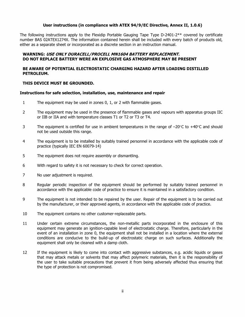
User instructions (in compliance with ATEX 94/9/EC Directive, Annex II, 1.0.6)
The following instructions apply to the Flexidip Portable Gauging Tape Type D-2401-2** covered by certificate number BAS 02ATEX1274X. The information contained herein shall be included with every batch of products old,
either as a separate sheet or incorporated as a discrete section in an instruction manual.
WARNING: USE ONLY DURACELL/PROCELL MN1604 BATTERY REPLACEMENT. DO NOT REPLACE BATTERY WERE AN EXPLOSIVE GAS ATMOSPHERE MAY BE PRESENT
BE AWARE OF POTENTIAL ELECTROSTATIC CHARGING HAZARD AFTER LOADING DISTILLED PETROLEUM.
THIS DEVICE MUST BE GROUNDED.
Instructions for safe selection, installation, use, maintenance and repair
1 The equipment may be used in zones 0, 1, or 2 with flammable gases.
2 The equipment may be used in the presence of flammable gases and vapours with apparatus groups IIC
or IIB or IIA and with temperature classes T1 or T2 or T3 or T4.
3 The equipment is certified for use in ambient temperatures in the range of –20°C to +40°C and should
not be used outside this range.
4 The equipment is to be installed by suitably trained personnel in accordance with the applicable code of
practice (typically IEC EN 60079-14)
5 The equipment does not require assembly or dismantling.
6 With regard to safety it is not necessary to check for correct operation.
7 No user adjustment is required.
8 Regular periodic inspection of the equipment should be performed by suitably trained personnel in
accordance with the applicable code of practice to ensure it is maintained in a satisfactory condition.
9 The equipment is not intended to be repaired by the user. Repair of the equipment is to be carried out
by the manufacturer, or their approved agents, in accordance with the applicable code of practice.
10 The equipment contains no other customer-replaceable parts.
11 Under certain extreme circumstances, the non-metallic parts incorporated in the enclosure of this
equipment may generate an ignition-capable level of electrostatic charge. Therefore, particularly in the event of an installation in zone 0, the equipment shall not be installed in a location where the external
conditions are conducive to the build-up of electrostatic charge on such surfaces. Additionally the equipment shall only be cleaned with a damp cloth.
12 If the equipment is likely to come into contact with aggressive substances, e.g. acidic liquids or gases that may attack metals or solvents that may affect polymeric materials, then it is the responsibility of
the user to take suitable precautions that prevent it from being adversely affected thus ensuring that the type of protection is not compromised.
ii
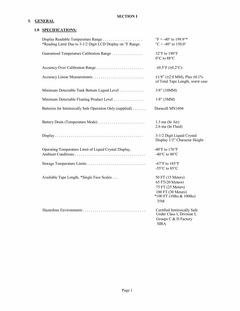
SECTION I I. GENERAL 1.0 SPECIFICATIONS: Display Readable Temperature Range . . . . . . . . . . . . . . . . . . . . °F = -40° to 199.9°* *Reading Limit Due to 3-1/2 Digit LCD Display on °F Range. °C = -40° to 150.0° Guaranteed Temperature Calibration Range . . . . . . . . . . . . . . . . 32°F to 190°F 0°C to 88°C Accuracy Over Calibration Range . . . . . . . . . . . . . . . . . . . . . . . . ±0.5°F (±0.2°C) Accuracy Linear Measurements . . . . . . . . . . . . . . . . . . . . . . . . . . ±1/8” (±2.0 MM), Plus ±0.1% of Total Tape Length, worst case Minimum Detectable Tank Bottom Liquid Level . . . . . . . . . . . . . 3/8” (10MM) Minimum Detectable Floating Product Level . . . . . . . . . . . . . . . . 1/8” (3MM) Batteries for Intrinsically Safe Operation Only (supplied) . . . . . . . Duracell MN1604 Battery Drain (Temperature Mode) . . . . . . . . . . . . . . . . . . . . . . . . 1.3 ma (In Air) 2.6 ma (In Fluid) Display . . . . . . . . . . . . . . . . . . . . . . . . . . . . . . . . . . . . . . . . . . . . . 3-1/2 Digit Liquid Crystal Display 1/2” Character Height Operating Temperature Limit of Liquid Crystal Display, -40°F to 176°F Ambient Conditions . . . . . . . . . . . . . . . . . . . . . . . . . . . . . . . . . . . . -40°C to 80°C Storage Temperature Limits . . . . . . . . . . . . . . . . . . . . . . . . . . . . . . -67°F to 185°F -55°C to 85°C Available Tape Length, *Single Face Scales . . . 50 FT (15 Meters)
75 FT (25 Meters) 100 FT (30 Meters)
*100 FT (10ths & 100ths) 35M
Hazardous Environments . . . . . . . . . . . . . . . . . . . . . . . . . . . . . . . . Certified Intrinsically Safe Under Class I, Division I, Groups C & D Factory SIRA
Page 1
KEVINP
65 FT(20 Meters)
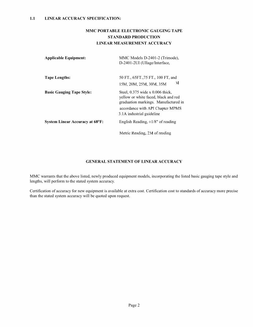
1.1 LINEAR ACCURACY SPECIFICATION:
MMC PORTABLE ELECTRONIC GAUGING TAPE STANDARD PRODUCTION
LINEAR MEASUREMENT ACCURACY Applicable Equipment: MMC Models D-2401-2 (Trimode), D-2401-2UI (Ullage/Interface, Tape Lengths: 50 FT., 65FT.,75 FT., 100 FT, and Basic Gauging Tape Style: Steel, 0.375 wide x 0.006 thick, yellow or white faced, black and red graduation markings. Manufactured in accordance qi System Linear Accuracy at 68°F: English Reading, ±1/8" of reading
GENERAL STATEMENT OF LINEAR ACCURACY MMC warrants that the above listed, newly produced equipment models, incorporating the listed basic gauging tape style and lengths, will perform to the stated system accuracy. Certification of accuracy for new equipment is available at extra cost. Certification cost to standards of accuracy more precise than the stated system accuracy will be quoted upon request.
Page 2
KEVINP
35M
KEVINP
accordance with API Chapter MPMS 3.1A industrial guideline
KEVINP
Rectangle
KEVINP
Text Box
15M, 20M, 25M, 30M, 35M
KEVINP
Text Box
Metric Reading, 2M of reading
1.2 SPECIAL FEATURES: Conductive Tape Surface to Drain Off any Static Charge Grounding Cable with Heavy Alligator Clamp Dual Purpose Spring Loaded Tape Crank and Tape Position Lock Watertight Electronics Construction with Sealed Switches All Stainless Steel Fasteners Nylon Coated Aluminum Reel Housing for Light Weight Portability Low Battery Display Indicator High Daylight Visibility with Liquid Crystal Display Push-button Night Light Rapid Multiple Temperature Measurements Easily Renewable Tape Wiper Manually Operated Vacuum / Pressure Relief Valve Primary and Secondary Tape Sight Glasses Anti-Wind Internal Spring Loaded Stop Level Sensor Internal Tape / Reel Confinement Springs Gas Tight Construction
Page 3
SECTION II 2.0 INTRODUCTION
2.1 The MMC closed Tri-Mode portable ullage, temperature and interface tape described herein incorporates extremely accurate instrumentation to provide three vital petroleum and other liquid tank measurements.
Measurement of surface ullage level of oil or other fluids to an accuracy and repeat- ability of ±1/8 inch.
Determination of the exact location of the ullage level of the interface layer exists when an oil-water mixture is contained within the same vessel.
Measurement in either Degrees F or Degrees C of the temperature of the fluid within a vessel, at any or several desired ullage levels, in rapid succession. Measurement is given to the nearest 0.1 degree and is accurate to ±0.5°F over the calibrated temperature ranges given in the specifications listed in Section I.
2.2 The MMC system utilizes a sensor suspended at the end of a fluoropolymer covered \ gauging tape wound on a reel assembly, The plastic covered steel gauging tape contains two isolated side conductors to carry the signal and power to the electronic circuit within the sensor barrel with the steel tape provides the ground return. The plastic surface of the tape has been treated to make it sufficiently conductive to prevent the build-up of static charges. Temperature indication is provided by a large digital liquid crystal display (LCD), housed within a sealed reel driving assembly. 2.3 Ullage and interface detection is provided by an audible signal obtained from a horn in the reel driving hub, when the bottom “U” gap in the sonic sensor is immersed in fluid. The audible signal heard, will be a continuous tone in a non-conductive fluid such as oil, gasoline, kerosene, etc., but will change to an interrupted tone when immersed in and fluid which is electrically conductive, such as water.
2.4 The system is certified as intrinsically safe for electrical equipment in hazardous atmospheres by SIRA, BV, DNV, CSA
2.5 The triple function temperature, interface, and ullage sensor is powered by a single 9 volt battery contained within the hub assembly. Battery drain is extremely low, (Approximately 1-1/4 Mili-amperes in either the ullage, interface or the temperature mode), insuring very long operation, without battery replacement. Low battery warning is provided at the upper left corner of the temperature display LCD, when the battery voltage has dropped to a level that would, with further operation, cause excessive errors in temperature readings.
Page 4
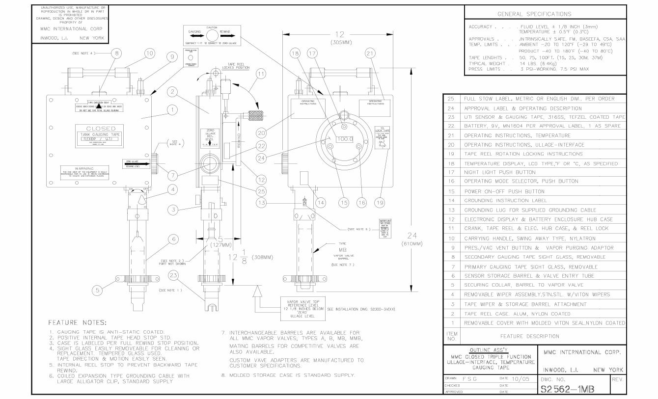
SECTION III 3.0. THEORY OF OPERATION 3.1 Drawing S-2562-1TR illustrates the main components of the closed temperature, ullage and interface system. A tape reel contained within the tape reel case (Part No. 2) contains the calibrated tape. The reel crank (Part No. 11) on the driving hub is used by the operator to raise and lower the sensing head assembly or sensor(Part No. 23), which is attached to the reel via the tape. In the stored position, the hub crank should be locked in the down position. (as shown on drawing S-2562-1TR). Before lowering or raising the tape, the reel lock crank must be unlocked by placing it in the vertical position. (See crank operating instruction label on rear side of the main housing).
3.2 The sensor head assembly (Part No. 23) contains two piezo-electric crystals, a pair of interface or conductivity pins, a temperature sensor, located in one of the conductivity pins and electronic circuit board. The sensor is connected electrically to the driving hub electronics by the two wires encased in the gauging tape plastic jacket, which covers and hermetically seals these wires and center graduated metallic gauging tape. The metallic tape is used as a ground
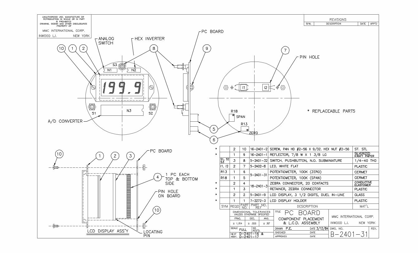
return conductor, which when including the two wires straddling it, form a rectangular three conductor transmission cable. 3.3 The electronic circuits in the hub assembly are comprised of a LCD digital display which provides temperature readings when the system is in the temperature mode; an analog to digital converter; a power on-off switch; a mode switch which permits operator to select the temperature mode or ullage/interface mode; a night light switch and ancillary electronic parts all assembled on a printed circuit board. A 9-volt battery power source and audio horn are located within the tape reel hub assembly below the P.C. board of the modular hub cover assembly. 3.4 When the system is placed in the ullage/interface mode, and as the sensor is immersed in a non-conductive fluid such as oil, a sonic signal originated by the sensor head circuits freely crosses the sensor gap and is detected, amplified and then transmission tape to the hub electronics board, which in turn drives a horn in the turning drum assembly(Part No. 12). A high pitched continuous audible signal is then emitted. When the sonic sensor is in air, the sonic signal does not cross the sensor gap and therefore, the horn is silent. 3.5 When the sonic sensor is immersed in a conductive fluid, such as the water layer side of an oil/water interface operation is as above except that the conductivity pins within the sensor gap now permit a minute current to flow between the pins. This current flow is detected by the sensor electronic circuitry with the sensor housing and suitability conditioned to cause the sonic signal to be periodically interrupted, yielding a “beeping” tone for operator identification. 3.6 When the system is placed in the temperature mode the ullage and interface circuits with- in the sensor barrel are de-energized, also disengaging the audio signals associated with the ullage/interface mode. The integrated circuit temperature sensor housed within the grounded interface pin now functions as an extremely accurate linear temperature to current transducer. As the temperature at the sensor rises, so does the temperature sensor current. By passing the temperature sensor current via the transmission tape, though the electronic component network, with the turning drum, input to an A to D converter is caused to vary linearly with temperature. Span control (R18) is adjusted to provide a fixed reference voltage, to scale for
Page 5

either a Centigrade or Fahrenheit reading device. Coded digital output from the A to D converter to the LCD Display is used to prove accurate and fast temperature readings. The The two potentiometer controls, R13 and R18, perform as a two point temperature calibration adjustment. A complete temperature calibration procedure is later described in this manual. (See Section VIII).
Page 6
SECTION IV 4.0 REQUIRED CONDITION AND RECOMMENDATION FOR SAFE USAGE The attention of the user of this apparatus is drawn to the possible hazards of ullage, interface and temperature measurements within flammable liquids, which are also known to be generators of static electricity. Adhering to the specific safety directives of your company, is the responsibility of the user. The following is a general guidance to safe usage, drawn from the advice and experience of various industry sources. The specific safety standards or directives of your company are to be strictly adhered to, with the general guidance given here being regarded as only a supplement to existing and established operating safety procedures. 4.1 REQUIRED CONDITION This apparatus must be earthed (grounded) to the liquid tank containment vessel or tank, before
and during introduction into the vessel. The earthed conductor must not be disconnected until the apparatus is completely withdrawn from the vessel being gauged. A suitable grounding cable is provided as part of the gauging unit. Proper grounding of this cable is the responsibility of the user.
4.2 RECOMMENDED SAFE USAGE CONDITIONS FOR THE TRIPLE FUNCTION CLOSED GAUGING TAPE: As the word “Closed” implies, the Tri-Mode gauging assembly shown on drawing S-2562-1TR has been carefully constructed to eliminate the escapee of cargo vapors to the atmosphere and to minimize exposure of operating personnel to these vapors. The sealed construction utilized, meets the current state and federal environmental requirements and provides the operator with a tool which greatly reduces potential occupational hazards. To assure that the above conditions will prevail, the “Closed” Tri-Mode gauging system should be entered into a cargo tank by means of a deck station vapor valve. 4.3 GROUNDING PRECAUTIONS: The “Closed” gauging tape assembly is to be hull grounded before and during its use for cargo gauging. Grounding of the gauging unit with the provided coiled grounding cable, should be completed before the vapor valve is opened, and any measurements conducted. The unit must remain grounded during all measurement procedures and until the sensor is fully wound back up into the case and the valve is closed. 4.3.1 The grounding of the unit, and adhering to the specific company safety standards or directives, is the sole responsibility of the operator. 4.3.2 Sensor entry into tanks or vessel immediately following a tank filling or loading operation of known static accumulator type petroleum products or other such flammable liquids, should not be attempted until, at least a period of 30 minutes has elapsed since the cessation of filling.
Page 7
4.3.3 Clean oil distillates are in general, known to be accumulators of static electricity due to their low conductivity (I.E., less than 100 Pica Siemens/Meter) and therefore may require relaxation periods of longer than 30 minutes before gauging is attempted. 4.3.4 The foregoing does not consider the use of anti-static additives to clean oils, as generally easing the need for proper precaution, unless actual and specific product testing has shown the product to have conductivity levels which eliminate the danger of static electric charging. 4.3.5 Sensor entry into tanks or vessels that have been water washed and which previously contained, or still partially contain petroleum products is not recommended unless a sounding pipe is provided, and approved for such use, or at least a period of five hours has elapsed since the completion of the working operation.
Page 8
SECTION V 5.0 GAUGING TAPE OPERATION 5.1 TANK ENTRY 5.1.1 The closed tape is installed into a vapor control valve in the same way as a restricted Flexi-Dip model. However, since the closed unit is sealed, and air cushion may occur, preventing the “Closed” tape from easily seating into the valve. By depressing the vacuum/pressure relief valve located on the top of the “closed” unit, the back pressure is released, allowing the unit to properly seat. The securing collar on the storage tube barrel is then tightened on the valve. 5.1.2 In addition, the vacuum/pressure relief valve can be used to determine the pressure within the case. Unscrewing the valve actuator cap exposes the actual valve. This valve is similar to an ordinary bicycle tire valve, and has its own attached to the valve by means of the exposed threaded valve stem. After pressure readings are complete, screw the valve actuator cap back onto the valve. 5.2 PRODUCT GAUGING OPERATION 5.2.1 The tape sensor is lowered and raised by unwinding and rewinding the tape crank/reel lock assembly, located on the reel driving hub is spring loaded. When the knurled knob of the crank/reel lock assembly is in the up position (perpendicular to the hub faceplate), the sensor can be freely lowered by turning the reel hub clockwise. To lock the reel at a desired tank depth, pull the knurled knob-up and out of its hub socket, and rotate it downward against the case. The reel is now locked. To un-lock the reel, reverse the above procedure. 5.3 DETERMINING CARGO LIQUID LEVEL Upon sonically determining the liquid level, (previously described), the gauging tape scale is read through the primary gauging sight port, located on the bottom side of the gauging assembly directly above the tape wiper housing. With a vapor valve properly installed, the tape reading will be corrected to the “zero” ullage reference plane. After completing a reading, re-wind the tape to its stowed position, being careful to engage the spring loaded tape wiper. 5.4 USE OF THE SECONDARY TAPE SIGHT PORT 5.4.1 A secondary tape sight port is provided for two main purposes. This port is located at the top of the unit, just below the carrying handle. With the carrying handle rotated to the case cover side, the secondary port may be viewed directly. 5.4.2 When lowering or raising the tape, the motion of the gauging tape should be observed through the secondary port. Viewing the tape through the
Page 9
secondary port gives the operator an immediate sense of tape direction, and approximate pay-out location of the sensor. When using a closed unit, as opposed to a restricted or open mode, a sense of tape direction may not be obvious to new operators. Therefore, the use of the secondary sight port becomes an important part of normal operations. 5.4.3 When tape motion is stopped, the tape reading seen in the “secondary” sight port is exactly 300 MM above “Zero” ullage reference Level.
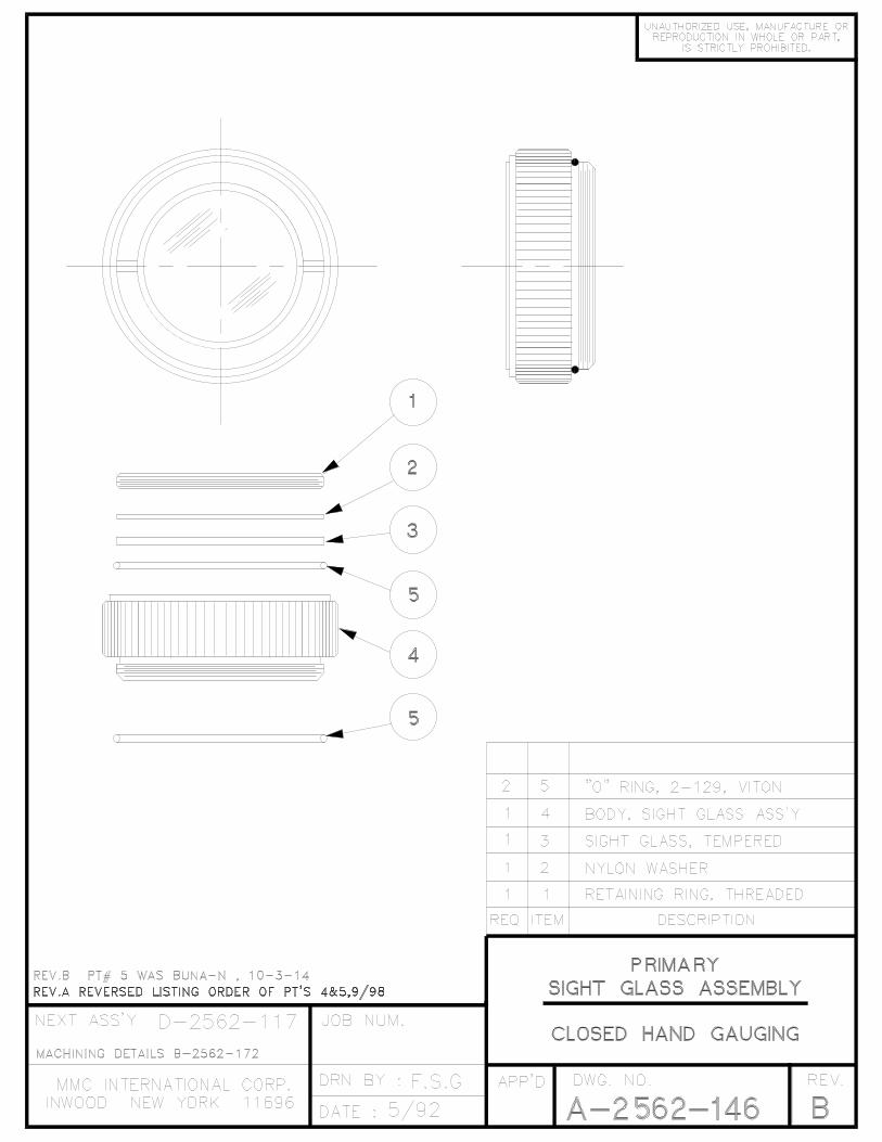
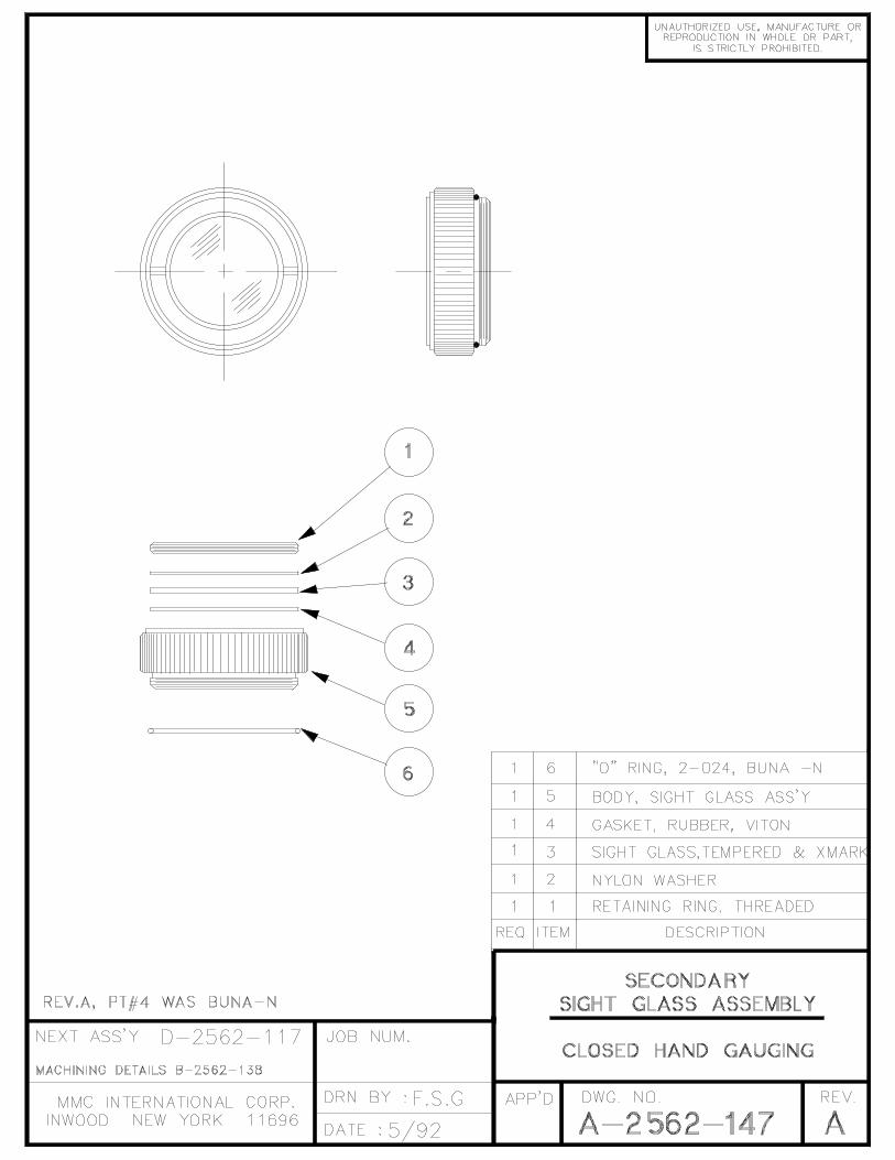
CAUTION: If the gauging tape reading seen at the secondary sight port is to be used as a recorded ullage, on 300 MM be subtracted for reading to correct the “zero” ullage reference plane. 5.4.4 In addition to the above functions, the secondary port provides an easy means of determining oil-water interface layer measurements. Since interface measurement are only concerned with relative differences, the previously mentioned 300 MM corrective subtraction becomes unnecessary. 5.5 TAPE OVER-WIND AND OTHER CONSIDERATION The closed gauging tape is provided with an automatic anti-wind mechanism. The purpose of this mechanism is to prevent an operator from re-winding the tape, after having fully payed-out the tape length, in an opposite fold over sense. When a tape is fully extended, a hard stop to further tape reel rotation will occur. Do not force this stop, as tape damage may result. When a tape travel stop is encountered, please observe the tape re-wind level for the proper re-wind direction. Internally, spring band fingers have been positioned around the tape take-up reel, to prevent the tape from coming out of the reel. However, in the event that the assembly is inadvertently dropped a good distance with a tape not fully rewound, the gauging case cover should be removed for an internal inspection. 5.6 Sight Port Glass Cleaning Occasionally, sight glass cleaning may become necessary. With reference to drawings A-2562-146 and A-2562-147, cleaning may be easily accomplished. Cleaning may be most easily accomplished by unscrewing the entire assembly, and washing in a suitable detergent.
CAUTION: To maintain the sealed integrity of the gauging assembly, be sure that the case seal “O” ring, Part No. 5 is in place upon re-installation of sight ports.
Page 10
SECTION V1 6.0 OPERATION (Refer to Figure 1) 6.1 FAMILIARIZATION WITH OPERATING CONTROLS AND FEATURES LOCATED ON THE TAPE REEL HUB COVER PANEL: 6.1.1 Turn on power by momentarily depressing the “Off/On” push-button switch (1) located at left of panel. The display should read 1XX.X* indicating that the system is in the Ullage/Interface mode. 6.1.2 Looking at the top left hand corner of the LCD display notice if the symbol “Lo Bat” appears. If the symbol is displayed, the battery voltage is low and the battery should be replaced (see Section VII Paragraph 7.5). Always replace the battery if “LO BAT” appears even though the digital display turns on. Temperature readings with a low voltage battery (below 7.0 Volts) are unreliable. 6.1.3 Once again, momentarily depress the power “On/Off” switch. Note that the display turns off. Always turn power off when the system is not in use to prolong battery life. Depress the “Off/On” switch once more. Display turns on and reads 1XX.X* indicating the Ullage/Interface mode. *NOTE: Due to an inherent digital uncertainty of the A to D converter, some digital displays, whenever in the Ullage/Interface mode, will read 00.0 instead of 1XX.XX. 6.1.4 Now momentarily depress the “Mode” switch at the right of the panel. The display should now switch to the temperature mode as indicated by a reading on on the display indicative of the temperature of the sensor tip. Once again depress the “Mode” switch and note that the display reads 1XX.X* (Ullage/Interface Mode). Depressing the “Mode” switch alternately changes the function from temperature to Ullage/Interface and vice versa. Depressing the power “Off/On” switch alternately turns power off or on regardless of which mode was in operation. However, when power is switched on again the system will always come on in the Ullage/Interface mode. 6.1.5 Depress the night light switch (3) at upper center of panel when it is too dark to see the display. The display background will illuminate and the reading should now be discernible. 6.2 Ullage/Interface Measurements: 6.2.1 If power is off, depress power “Off/On” push-button switch. The system comes on in Ullage/Interface mode (display reads 1XX.X). 6.2.2 If the power was on and the system is in temperature mode, depress the “Mode” switch at right of panel to alter function to Ullage/Interface. 6.2.3 Make sure “LO BAT” Does not show at left upper corner of display.
Page 11
6.2.4 After grounding the assembly, insert the barrel of the gauging into the valve. Un-lock the tape reel lock, by rotating the brass lock thumbscrew. Grasp the knurled reel crank hand and lower the sensor head tape assembly, which contains the sonic sensor, into the tank. Always exert a restraining force to prevent the sensor from descending too rapidly or free falling.
CAUTION!
Under no circumstances should the reel and tape be permitted to unwind without restraint. Permanent damage may be incurred to the sensor head or to the calibrated tape if the head is permitted to fall freely. 6.2.5 Lower the sensor head slowly until a tone steady is heard. If the surface of the fluids is oil or other non-conductive fluid, a continuous audible tone will be heard. If the surface of fluid is water or other conductive fluid, the audible tone heard, will be a “beeping” tone. 6.2.6 Define measurement by raising the sensor / sensor head until the sound just ceases. Lower until sound is just heard again, to refine ullage level. 6.2.7 Read ullage on tape through the primary gauging sight port, (see Section V, Paragraph 5.3), record this reading as the surface liquid ullage level. 6.2.8 To find the oil-water interface point, continue to lower the sensor into fluid, noting that the audible tone is continuous. When the audible signal changes to a “Beeping” tone, the sensor has entered the water column underneath the oil. 6.2.9 Raise the sensor very slowly until the tone once again becomes continuous. Repeat if necessary to refine water entry point (Interface level). 6.2.10 Again, read the ullage on the tape. By subtracting the first reading obtained (step 7) from this reading, the total product depth is thus determined. By subtracting the second water level ullage from the maximum tank depth, water level innage is determined.
6.2.11 When the measurement is completed, place the spring loaded wiper knob in the “On” position while rewinding the tape until sensor is stored with in the vapor valve entry barrel. Do not close the vapor valve until the fully
“stowed” position is confirmed, by noting that yellow pop-up button on top of the wiper housing is “up” . 6.2.12 Lock the reel by placing the crank/reel lock in the down position (parallel to hub). Depress power “Off/On” switch to conserve battery power. 6.2.13 Close the vapor valve, disconnect the valve securing cap, remove the gauging unit, disconnect the grounding cable. Replace the vapor valve cap.
Page 12
6.3 TEMPERATURE MEASUREMENT PROCEDURE 6.3.1 If power is off, turn unit on by depressing “Off/On” push-button switch. Unit comes on in Ullage/Interface mode. Depress “Mode” push-button switch to select temperature. 6.3.2 If unit was on and in Ullage/Interface mode, simply press the “Mode” push-button to select temperature. 6.3.3 Make sure “LO BAT” does not show at left upper corner of display. If “LO BAT” appears, replace battery even though the digital display turns on. The display may continue to operate even though the battery voltage is below normal. Temperature reading however, may be in error. 6.3.4 Ground the assembly, release the turn handle reel lock. Lower the sensing sensor to the deepest reading desired. Make sure to exert restraining force while lowering. 6.3.5 When the desired temperature ullage level is reached, allow the sensor to at this point for at least two (2) minutes. Then joggle the sensing sensor up and down, approximately 6” above and below the desired measurement level until the displayed temperature reading settles. Record this reading. For heavy crude oil products, the joggling procedure is a necessity to insure accurate readings. The viscous nature and low thermal conductivity properties of these petroleum products, makes the joggling procedure a necessity to insure accurate temperature in a minimum amount of time. 6.3.6 Raise the sensor to the next ullage level to be measured. Repeat step 6.3.5. Continue raising sensor to all levels at which readings are desired. 6.3.7 When the measurements are complete, push “Off/On” button to turn off and conserve battery power. Rewind the tape into the carriage reel assembly. Wipe the tape as it is rewound by placing the spring loaded wiper in the “On” position. 6.3.8 Lock the reel by rotation reel lock crank down, position. Follow the same final procedure as described in step 6.2.13 above
Page 13
SECTION VII 7.0 CARE AND MAINTENANCE Proper care and maintenance should be practiced to maintain long trouble free and accurate service and to maximize battery life, as follows: 7.1 When not in use, make sure power is off as evidenced by display being extinguished. 7.2 Store sensor head assembly in the fully wound position and store in a dry location. Do not allow the instrument to remain for long periods in direct sunlight, or store in temperature above 125° F, or in temperature below freezing. Such temperatures may damage the liquid crystal display. 7.3 Wipe excess oil or water from tape, and sensor head. Each time the sensor is raised from the tank, hold the spring loaded tape wiper switch in the “On” position. 7.4 Never permit tape and sensor head to unwind freely (control speed of descent by usage of a restraining force on crank). 7.5 Battery Replacement (See approval label for correct type) The battery should be replaced whenever the “Lo Bat” symbol appears at the upper left corner of the display. If the sensor is used to obtain temperature readings when the battery is low, large errors may result. Always replace battery in a gas free atmosphere. Remove the six machine screws on the hub cover. Lift the cover with its attached P.C. Board. The battery is retained within the reel turning drum a spring clip battery holder. Remove the battery from the battery cap connector. Replace the battery with a fresh battery of the type listed on the approval label only. Take care to align the viton cover gasket, cover, and machine screw fasteners when re-assembling to tape reel hub.
Page 14
SECTION VIII 8.0 CALIBRATION PROCEDURE 8.1 Ullage: The ullage circuits do not require calibration in the field with proper care and handling the equipment should function indefinitely. 8.2 Temperature Sensor Calibration The temperature sensor and its associated electronic circuitry have been accurately
calibrated at the factory . Temperature Calibration by MMC is recommended at twelve-month intervals, with periodic checks being carried out as necessary between these intervals.
. Before attempting any calibration, make sure that the battery is at a proper voltage level as evidenced by the fact that "Lo Bat" does not appear at the upper left corner of the display when the equipment is powered. Low battery voltage will produce errors in temperature readings. If "Lo Bat" appears on the display, check battery voltage and replace. If necessary, calibration of the temperature sensor may be accomplished as follows: 8.2.1 Use thermometers accurate to ±0.1° and preferably graduated in one-tenth degree intervals. If mercury thermometers are employed, use two separate thermometers to provide greater resolution. One to cover low temperatures cover low temperatures and the other to cover the high temperatures.
8.2.2 Remove the six machine screws on the hub cover. Lift the cover and attached P.C. Board from Hub exposing two potentiometers at back lower left of board. Lowest potentiometer, marked (R13), is the “Zero” control and the potentiometer to the left and above, marked (R18), is the “span” control. (See drawing B-2401-31).
8.2.3 Turn display on by depressing power "Off/On" button momentarily. Place system in
temperature mode by depressing “Mode” switch. Display should now read temperature at sensor tip.
8.2.4 Prepare two temperature baths, a cold bath of approximately one gallon of water, and a
hot bath of approximately one gallon of water at a temperature at least 60° higher than the cold bath.
8.2.5 Place the sensor in the cold bath with thermometer and stir the bath well to equalize
temperature. Keep sensor and thermometer together at approximately the same point in the bath.
8.2.6 Record: Sensor Cold Reading as = pc (as read from digital display) Record Reference: Thermometer Cold reading as = tc 8.2.7 Repeat the above procedure in a hot bath. 8.2.8 Record: Sensor Hot Reading as = ph (as read from digital display) Record Reference: Thermometer Hot Reading as = th
8.2.9 Calculate Zero Correction = tc (ph - pc) - pc th – tc
Page 15
8.2.10 Place sensor in cold bath. Stir and wait until sensor reading on display stabilizes. Note reading and then adjust “Zero” control potentiometer marked (R13) so that the zero correction calculated in step 8.2.9. above is
added to or subtracted from the sensor reading. If the answer in step 8.2.9 above is positive, add the correction, if negative, subtract. 8.2.11 Now place thermometer in the cold bath with the sensor and stir. Now adjust the “span” potentiometer until the two reading are equal (the displayed reading, and the reading of reference thermometer). 8.2.12 Check readings in hot bath. Slight touch-up of “Span” control may be required. Normally not more than a ±0.1 degrees correction is necessary if the calculated measure “Cold” temperature procedure has been performed correctly. The above method allows the operator to perform the calibration in one step. If desired, and particularly if the error is minor, an adjustment of zero may be performed in the cold bath to equal the thermometer reading. Then the span may be adjusted in the hot bath. However, this procedure requires repetition until both cold and hot bath readings are correct without further adjustment in either cold or hot baths.
Page 16
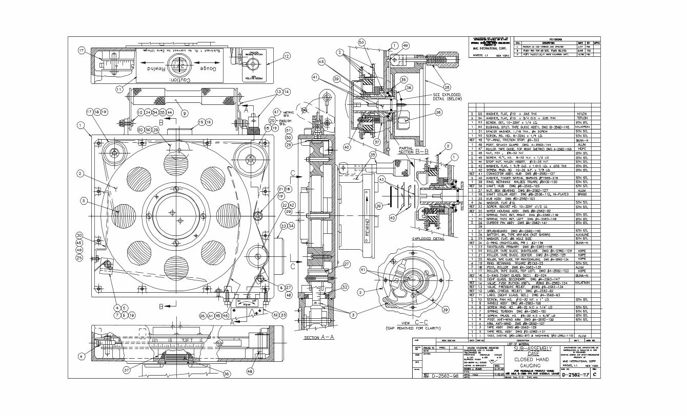
SECTION IX 9.0 GAUGING TAPE REPLACEMENT (With or without new sensor attached) (SEE DRAWING D-2562-117) The gauging tape used for the Trimode closed gauging system is similar but not inter -changeable with the gauging tapes used for restricted gauging systems. The tapes used are bright white faced steel core type, which have been encapsulated with a tefzel jacket. (Tefzel is a registered trade name of the Dupont Corporation). The tapes is terminated at the display electronics hub PCB module connection points, by soldered leads within tape reel internal core. The sensor is connected to the tape by means of a quick connect plug to the tape socket plug. As with all tefzel coated MMC gauging tapes, the outer surfaces are factory treated to render the surfaces of the tapes anti-static properties. The patented process to achieve the desirable anti-static condition, is not defeated by tape wiping or cleaning with standard petroleum based solvents. Gauging tape replacement is not difficult, but requires careful attention to the travel path of tapes as it exits from the tape reel assembly, passes over the interior guide rollers, cursor pin assembly, anti-chafing rollers and on through the wiper housing . 9.1 To replace a tape, remove the vapor valve barrel, tape wiper assembly, stub barrel connector and main reel housing cover. 9.2 With the main reel cover removed, the tape reel and tape pay-out through the wiper housing can be seen. Take careful note of how the tape is directed around the various roller and guides. In particular, note the tape path between the upper right hand roller, the guide roller just below it, cursor pin assembly, and tape wiper housing split ring bushing. 9.3 With the above in mind, or recorded with a simple hand sketch, the screws holding the reel hub cover can be removed. The reel hub cover is both a reel interior cover, and also the reel drive shaft to reel driver. The underside of the cover has a crossbar, which couples it to the reel drive shaft assembly. The coupling action is accomplished by means of the cover cross bar engaging the slotted ends of the drive shaft assembly. With the reel hub cover removed, note that the outer reel plate is still retained to the reel hub core by a single flat head screw. Note that directly opposite the flat head screw (180° away) a small pinhead can be seen in a reel plate hole on the same screw hole diameter as the flat head screw. Also, note that the screw hole pin, is at this time, aligned with drive shaft coupling slots. The interior electrical connector hub end of the gauging tape is now also in view. Note the placement of the terminating epoxy molding piece at the end of the tape within the hub core. Also, note the three wires leading to a connector and a separate black ground wire emanating from the molding remove the black wire screw and unplug the connector by
Page 17
Squeezing the mating connector at the ribbed sides which are at opposite sides of connector shell. Remove the flat head screw holding the outer reel plate to the reel core. Note that the spring-loaded anti-rotation arm can now be seen pressing against the outside. layer of tape. 9.4 Next, unreel the tape and sensor head until the anti-rotation devices stops the tape from unwinding further. The tape may now, with a little manipulation, be lifted out and pulled out from the rollers and through the hole exiting from the barrel. 9.5 A new tape can now be installed in reverse manner. Be sure that the tape numerals face in the same direction as the previous tape numerals faced. Thread the end of the new tape up through the barrel, through the rollers and finally make sure to correctly place the end with the molding and connector into the hub core insure that the anti-rotation arm is now again pressing against the outside layer of the new tape. Now wind the tape on to the reel by spinning the tape reel in a counter clockwise direction.. Next, plug the connector into its mater and reconnect the ground wire. Replace the outer reel plate and it’s flat head screw attachment to the reel core. With the partially assembled tape reel still freewheeling on the drive shaft, align the slotted end of the drive shaft, to be in-line with the flat head screw on the outer reel plate and the reel core stop pin directly across from it. The reel hub cover can now be re-installed by visually aligning its underside cross bar with the drive shaft end slots. Replace all core cover screws. 9.6 The main reel housing cover can now be replaced. The screws provided for cover attachment to the main reel housing, have built-in “O” ring head seals. Do not replace these screws with ordinary machine screws. Re-install the wiper housing, being sure to replace its mounting plate to the wiper gasket. Re-install the stub barrel piece into the tape wiper housing. Be sure to first replace the split full stop bushing into the of the barrel adapter. As a final check, the gauging tape may be hand unwound from the reel to its full length at which time the anti-rotation arm engagement should be confirmed. Re-wind the freed tape with some slight hand drag. 9.7 If a new sensor has also been replaced with a new tape, perform a temperature calibration in accordance with Section VIII. This is a mandatory procedure as the new temperature sensor components must be calibrated to the electronic board within the reel turning drum.
Page 18
SECTION X 10.0 HUB COVER AND P.C. BOARD REPLACEMENT To replace the turning drum hub cover and P. C. Board, follow the steps outlined below: 10.1 Remove the six machine screws from the hub cover, and extract cover, gasket and P.C. Board. 10.2 Unplug battery cap. 10.3 Unsolder wires that go to small horn (Note that these wire originate from same strip that connects battery cap). 10.4 Now carefully examine three conductor strips that originate at upper right hand corner of P.C. board. These wires may not be the same color code as the replacements hub P.C. Board and it is important that they be connected to the correct points. Note that one wire (ground) has a terminal lug attached and therefore replaces the previous wire with terminal lug. 10.5 Now make a note of the wires that go to top and bottom splices of outer tape conductors. One of these wires goes to a point on P.C. Board Labeled "+V". The other to a point on P.C. Board labeled "SIG". Note which goes to top and which goes to bottom conductor. For example: "SIG" to top connector and "+V" to bottom connector. 10.6 Unsolder spliced conductors and remove the nut ground connecting the gauging tape to the driving drum. This now completes disassembly and the old hub assembly can be put aside. 10.7 Position new hub cover and P.C. Board and solder to horn and insulate the two free wires originating from the battery cap strip line. The polarity of these two wires is not important. 10.8 Reconnect ground wire with terminal lug to driving drum ground post and replace and tighten nut. 10.9 Re-solder and insulate “+V” and "SIG" wire to outer tape conductors taking careful notice of where they originated. (See Step 10.5 above) 10.10 Replace battery and connect battery cap. 10.11 Re-assemble hub cover and attached P. C. Board with six machine screws being careful to line up neoprene gasket. 10.12 Perform temperature calibration in accordance with Section VIII. .
Page 19
SECTION XI 11.0 FAULT FINDING (SEE DRAWING B-2401-31) The following section covers only simple faults that may occur. No attempt has been made in this section to cover highly technical faults. PROBLEM NO. 1: Unit does not turn on when power "OFF/ON" switch is depressed. PROCEDURE & EXPLANATION: If unit does not turn on at all, check battery voltage using a voltmeter. If battery voltage is lower than four (4) volts because units has been accidentally stored for a lengthy period with power on the voltage is too low to illuminate display. Replace battery. (See Section VII Paragraph 7.5). If battery is okay, check power “ON/OFF” switch using an OHM meter. Switch should normal show an open circuit. When depressed OHM meter reading should be less than 2 Ohms. If switch is okay integrated circuit chip is probably at fault. Return to factory or service center for repair. PROBLEM NO. 2: Unit stays on all the time, even though "OFF/ON" push-button is depressed. PROCEDURE & EXPLANATION: This symptom is usually indicative of a faulty power “OFF/ON” push-button switch. Check the switch with an Ohmmeter as explained in Problem No. 1 above. PROBLEM NO. 3: Unit turns on and off, however, when "Mode" switch is depressed system does not switch to temperature it stays in Ullage/Interface mode always. PROCEDURE & EXPLANATION: Use OHM meter to make sure "Mode" switch is normally open and when depressed is closed. If switch is faulty replace. If switch check out okay, problem is probably an integrated circuit chip. Return to factory for repair. PROBLEM NO. 4: Temperature readings are erroneous PROCEDURE & EXPLANATION: A.) When display is on, does the "Lo Bat" appear at upper left corner? If so, replace battery with a new battery following procedure given in Section VII, Paragraph 7.5. B.) If “Lo Bat” does not appear and display contrast in temperature mode is not good and in particular the decimal point is very faint or not visible, check battery voltage using voltmeter. If voltage has fallen below 5.0 “Lo Bat” may not appear. Usually, under these conditions the temperature readings will show extreme errors. C.) If battery checks okay, it is possible that the temperature sensor in the sensing head may have been damaged by dropping unit or unit may be out of calibration, due to severe exposure or abuse.
Page 20
D) Determine if sensor is still useful by following the calibration procedure given is Section VIII. E) If fault not corrected, return to MMC for repair. Sensor or integrated circuit chip may require replacement. PROBLEM NO. 5: Liquid Crystal Display (LCD) does not function properly one or more segments stay on or off all the time producing strange figures. PROCEDURE & EXPLANATION: Display contact may be corroded or dirty. Remove hub cover and associated P.C. Board by first removing six machine screws. Remove the three push- button switches and seal boot fasteners. P.C. board and associated display may now be separated from coverplate .Remove LCD display bezel (see DWG. B -2401-31) by first removing two machine screws and nuts. Carefully lift bezel and liquid crystal display from blue connector. Make sure that the long thin elastomer contact strips that fit into the top and bottom horizontals slots of the connector are not lost. Remove connector with associated contact strips exposing P.C. Board contacts. Use a good non-oil contact cleaner to clean P.C. Board contacts. If corroded or dirty, wipe contact (bottom side only) with cotton swab wetted with alcohol, being careful not to saturate LCD with fluid.
CAUTION: Do not spray contact cleaner on LCD display or permanent damage may be incurred. Re-assemble in reverse order making sure elastomer contact strips are inserted properly in blue connector horizontal slots. Note that blue connector bottom pins fit into mating hose on P.C. Board for proper alignment. If above procedure does not cure problem then either display or integrated circuit A/D converter is at fault. Spare display can be substituted to isolate problem. Order from MMC together with new connector. PROBLEM NO. 6: Display is damaged, permanently discolored broken. PROCEDURE & EXPLANATION: Order new display and connector from MMC and follow procedure given in Problem No. 5 to replace. PROBLEM NO. 7: Unit operates properly in temperature mode, however, when placed in ullage mode, horn does not sound in oil or in water, or sound is extremely weak. PROCEDURE & EXPLANATION: Sonic sensor has probably been damaged by being dropped and replacement may be required. Check unit in a container of clean lube oil, and then in a container of water. If sensor does not respond per operating procedure, then sensor replacement is probably necessary. Return to factory.
Page 21
APPENDIX
Page
Number
A. MMC Warranty Statement 23
B. Glossary of Approvals 24
C. Temperature Conversion Chart 25
D. Guideline for Tape Repair 26
E. List of Corrosive Chemicals 27
F. List of Drawings 28
Page 22
WARRANTY MMC SONIC ULLAGE, INTERFACE, TEMPERATURE & TRIPLE FUNCTION TAPES: The seller, MMC or its licensed agents, fully warrants equipment of it manufacture against defects in materials or workmanship for a period of one year from the date of shipment. No other warranty period, in excess of one year, may be expressed or implied by sub-agents or others, unless authorized in writing by MMC. The liability of the seller under this warranty is limited, at seller’s option, solely to repair or replace with equivalent equipment. The seller, upon the expiration of the warranty period, has the option to apply a limited credit, not to exceed the original equipment sales price, toward the purchase of a new piece of equipment, if returned equipment is beyond reasonable repair. In any event, non-warranty repair charges will be quoted to buyer, for authorization, before repair work commences. In the Event of Returns for Warranty Repairs: A. The buyer is to notify the seller in writing upon discovery of the defects.
B. Upon receipt of written authorization from the seller, the equipment is to be returned as directed, transportation prepaid by the buyer.
C. Buyer is to disclose the use of this product within hazardous chemical substances. It is the responsibility of the buyer to clean or decontaminate this product before returning for repairs. Buyer’s refusal will void repair warranty at seller’s option. D. If seller’s examination of such equipment disclosed to his satisfaction that defects were not caused by negligence, misuse, improper installation, accident or unauthorized repair or alteration by the buyer, repairs will be immediately affected. E. Buyer is to provide shipping instructions for the return, including mode of transportation. This warranty does not include mechanical parts failure due to wear or corrosion from normal usage, nor does it cover limited life electrical components, or elastomer seals. This warranty is in lieu of all other warranties, expressed or implied, including that implied of fitness for a particular purpose to the original purchaser or to any other person. Seller shall not be liable for consequential damages of any kind. IMPORTANT: The equipment has been certified as intrinsically safe instrument for only those classes or categories of hazardous areas so stated on the equipment label, bearing the mark of the applicable approval agency. No other usage is implied or otherwise authorized. Unauthorized repair or component replacement by the user, will void this warranty, and may affect the intrinsic safety of the equipment. JANUARY 2000
Page 23
GLOSSARY OF APPROVALS
MAJOR APPROVAL STANDARDS & GOVERNMENT SPECIFICATIONS ADOPTED BY MMC INTERNATIONAL CORP. FOR
CERTIFICATION, MANUFACTURE, INSPECTION, CALIBRATION AND TESTING
INTRINSICALLY SAFE APPROVALS
SIRA Sira Certification Service CSA Canadia Standards Association EECS Electrical Equipment Certification Service (U.K.)
GOVERNMENT REGULATORY BODIES APPROVALS BV Bureau of Veritas EECS Electrical Equipment Certification Service (U.K.)
INDUSTRY RECOGNIZED INSPECTION BODIES APPROVALS ABS American Bureau of Shipping CCS China Classification Society DNV Det Norske Veritas (Norway) LLOYD'S Lloyd's of London (U.K.) BV Bureau of Veritas
GAUGING TAPE AND OTHER MEASUREMENT SPECIFICATION FEDERAL United States Government Specification NIST National Institute of Standards & Technology Test API American Petroleum Institute (Partial Adaptation) ASTM American Society for Testing Materials
PERIODIC FACTORY INSPECTIONS BY REGUALTORY BODIES
SIRA Performs annual inspections for SIRA for equipment approval DNV Performs annual inspection CSA Performs annual inspection BV Performs annual inspection
Page 43
KEVINP
Text Box
KEVINP
Rectangle
KEVINP
Text Box
Page 24
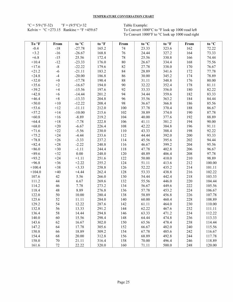
TEMPERATURE CONVERSATION CHART
°C = 5/9 (°F-32) °F = (9/5°C)+32 Table Example: Kelvin = °C +273.15 Rankine = °F +459.67 To Convert 1000°C to °F look up 1000 read left To Convert 1000°F to °C look up 1000 read right
To °F From to °C to °F From to °C to °F From to °C -0.4 -18 -27.78 165.2 74 23.33 323.6 162 72.22 +3.2 -16 -26.67 168.8 76 24.44 327.2 164 73.33 +6.8 -15 25.56 172.4 78 25.56 330.8 166 74.44 +10.4 -12 -23.33 176.0 80 26.67 334.4 168 75.56 +17.6 -8 -22.22 179.6 82 27.78 338.0 170 76.67 +21.2 -6 -21.11 183.2 84 28.89 341.6 172 77.78 +24.8 -4 -20.00 186.8 86 30.00 345.2 174 78.89 +32.0 +0 -17.78 190.4 88 31.11 348.8 176 80.00 +35.6 +2 -16.67 194.0 90 32.22 352.4 178 81.11 +39.2 +4 -15.56 197.6 92 33.33 356.0 180 82.22 +42.8 +6 -14.44 201.2 94 34.44 359.6 182 83.33 +46.4 +8 -13.33 204.8 96 35.56 363.2 184 84.44 +50.0 +10 -12.22 208.4 98 36.67 366.8 186 85.56 +53.6 +12 -11.11 212.0 100 37.78 370.4 188 86.67 +57.2 +14 -10.00 215.6 102 38.89 374.0 190 87.78 +60.8 +16 -8.89 219.2 104 40.00 377.6 192 88.89 +64.4 +18 -7.78 222.8 106 41.11 381.2 194 90.00 +68.0 +20 -6.67 226.4 108 42.22 384.8 196 91.11 +71.6 +22 -5.56 230.0 110 43.33 388.4 198 92.22 +75.2 +24 -4.44 233.6 112 44.44 392.0 200 93.33 +78.8 +26 -3.33 237.2 114 45.56 395.6 202 94.44 +82.4 +28 -2.22 240.8 116 46.67 399.2 204 95.56 +86.0 +30 -1.11 244.4 118 47.78 402.8 206 96.67 +89.6 +32 0.00 248.0 120 48.89 406.4 208 97.78 +93.2 +24 +1.11 251.6 122 50.00 410.0 210 98.89 +96.8 +36 +2.22 255.2 124 51.11 413.6 212 100.00
+100.4 +38 +3.33 258.8 126 52.22 435.2 214 101.11 +104.0 +40 +4.44 262.4 128 53.33 438.8 216 102.22 107.6 42 5.56 266.0 130 54.44 442.4 218 103.33 111.2 44 6.67 269.6 132 55.56 446.0 220 104.44 114.2 46 7.78 273.2 134 56.67 449.6 222 105.56 118.4 48 8.89 276.8 136 57.78 453.2 224 106.67 122.0 50 10.00 280.4 138 58.89 456.8 226 107.78 125.6 52 11.11 284.0 140 60.00 460.4 228 108.89 129.2 54 12.22 287.6 142 61.11 464.0 230 110.00 132.8 56 13.33 291.2 144 62.22 467.6 232 111.11 136.4 58 14.44 294.8 146 63.33 471.2 234 112.22 140.0 60 15.56 298.4 148 64.44 474.8 236 113.33 143.6 62 16.67 302.0 150 65.56 478.4 238 114.44 147.2 64 17.78 305.6 152 66.67 482.0 240 115.56 150.8 66 18.89 309.2 154 67.78 485.6 242 116.67 154.4 68 20.00 312.8 156 68.89 492.8 244 117.78 158.0 70 21.11 316.4 158 70.00 496.4 246 118.89 161.6 72 22.22 320.0 160 71.11 500.0 248 120.00
Page 25
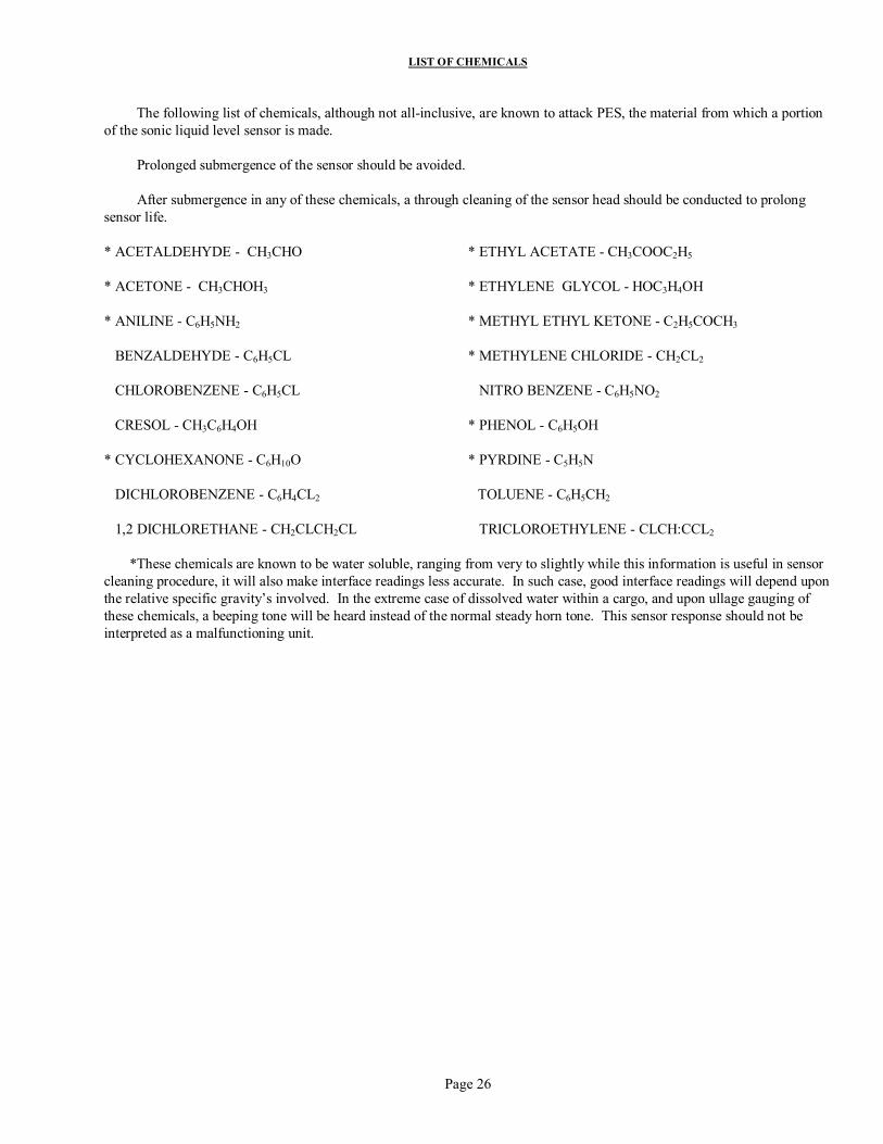
LIST OF CHEMICALS The following list of chemicals, although not all-inclusive, are known to attack PES, the material from which a portion of the sonic liquid level sensor is made. Prolonged submergence of the sensor should be avoided. After submergence in any of these chemicals, a through cleaning of the sensor head should be conducted to prolong sensor life. * ACETALDEHYDE - CH3CHO * ETHYL ACETATE - CH3COOC2H5 * ACETONE - CH3CHOH3 * ETHYLENE GLYCOL - HOC3H4OH * ANILINE - C6H5NH2 * METHYL ETHYL KETONE - C2H5COCH3 BENZALDEHYDE - C6H5CL * METHYLENE CHLORIDE - CH2CL2 CHLOROBENZENE - C6H5CL NITRO BENZENE - C6H5NO2 CRESOL - CH3C6H4OH * PHENOL - C6H5OH * CYCLOHEXANONE - C6H10O * PYRDINE - C5H5N DICHLOROBENZENE - C6H4CL2 TOLUENE - C6H5CH2 1,2 DICHLORETHANE - CH2CLCH2CL TRICLOROETHYLENE - CLCH:CCL2 *These chemicals are known to be water soluble, ranging from very to slightly while this information is useful in sensor cleaning procedure, it will also make interface readings less accurate. In such case, good interface readings will depend upon the relative specific gravity’s involved. In the extreme case of dissolved water within a cargo, and upon ullage gauging of these chemicals, a beeping tone will be heard instead of the normal steady horn tone. This sensor response should not be interpreted as a malfunctioning unit.
Page 26
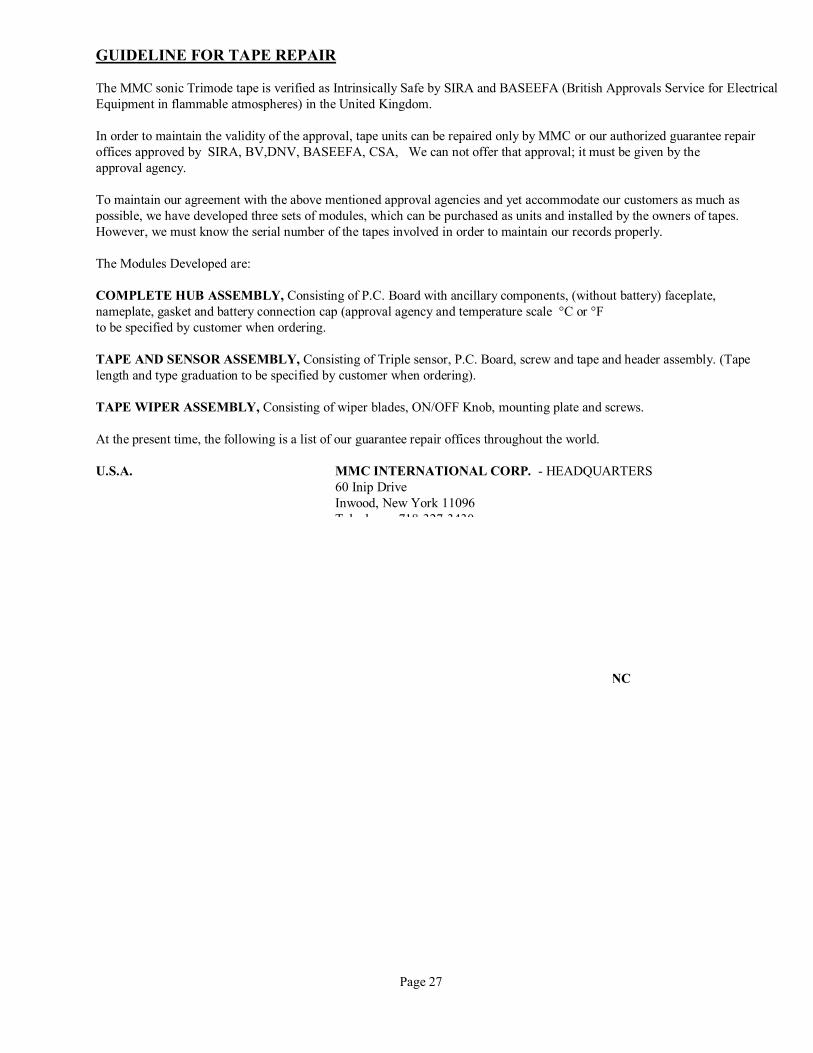
GUIDELINE FOR TAPE REPAIR The MMC sonic Trimode tape is verified as Intrinsically Safe by SIRA and BASEEFA (British Approvals Service for Electrical Equipment in flammable atmospheres) in the United Kingdom. In order to maintain the validity of the approval, tape units can be repaired only by MMC or our authorized guarantee repair offices approved by SIRA, BV,DNV, BASEEFA, CSA, We can not offer that approval; it must be given by the approval agency. To maintain our agreement with the above mentioned approval agencies and yet accommodate our customers as much as possible, we have developed three sets of modules, which can be purchased as units and installed by the owners of tapes. However, we must know the serial number of the tapes involved in order to maintain our records properly. The Modules Developed are: COMPLETE HUB ASSEMBLY, Consisting of P.C. Board with ancillary components, (without battery) faceplate, nameplate, gasket and battery connection cap (approval agency and temperature scale °C or °F to be specified by customer when ordering. TAPE AND SENSOR ASSEMBLY, Consisting of Triple sensor, P.C. Board, screw and tape and header assembly. (Tape length and type graduation to be specified by customer when ordering). TAPE WIPER ASSEMBLY, Consisting of wiper blades, ON/OFF Knob, mounting plate and screws. At the present time, the following is a list of our guarantee repair offices throughout the world. U.S.A. MMC INTERNATIONAL CORP. - HEADQUARTERS 60 Inip Drive Inwood, New York 11096 Telephone: 718-327-3430 Facsimile: 516-371-3134 ENGLAND MMC (EUROPE) LTD. South Nelson Road South Nelson Industrial Estate Cramlington, Northumberland NE23 9WF Telephone: 0670-738111 Facsimile: 0670-738789 USA HYDRAULIC * AUTOMATION CONTROLS INC CONTROLS INC 806 W. 14th Street Long Beach CA 90813 Telephone: 562-435-3144 Facsimile: 562-435-2266 USA MGM MARINE, INC 5901 Bayway Drive Baytown Texas 77520 Telephone: 281-424-3587/ 800-985-5464 Facsimile: 281-424-874 JAPAN MMC (ASIA) LTD. 7-7, 2-Chome, Kotonoo-Cho Chuo-Ku, Kobe 651 Japan Telephone: 078-251-1033 Facsimile: 078-252-0265 Page 27
KEVINP
Rectangle
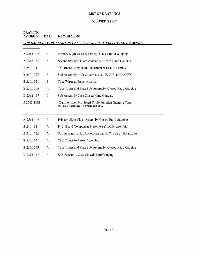
LIST OF DRAWINGS
“CLOSED TAPE” DRAWING NUMBER REV. DESCRIPTION FOR GAUGING TAPE LENGTHS 35M PLEASE SEE THE FOLLOWING DRAWINGS
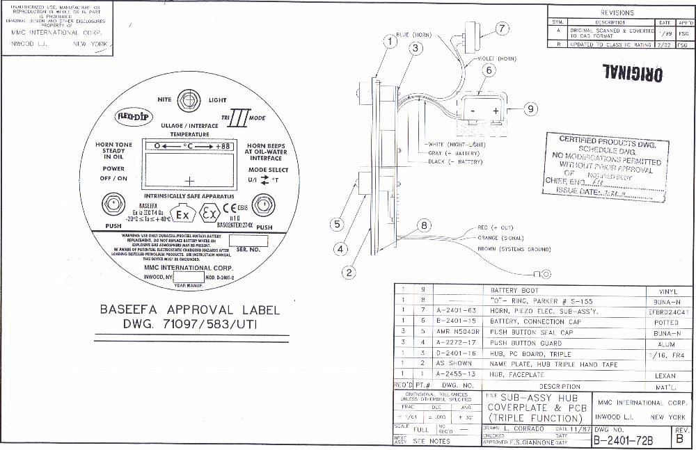
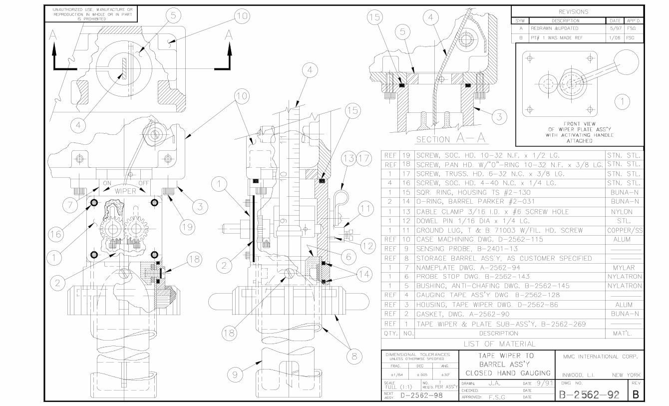
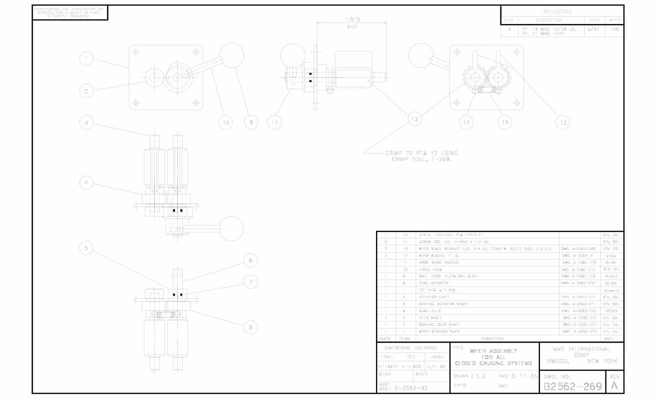
A-2562-146 B Primary Sight Glass Assembly, Closed Hand Gauging A-2562-147 A Secondary Sight Glass Assembly, Closed Hand Gauging B-2401-31 - P. C. Board Component Placement & LCD Assembly B-2401-72B B Sub-Assembly, Hub Coverplate and P. C. Board), ATEX B-2562-92 B Tape Wiper to Barrel Assembly B-2562-269 A Tape Wiper and Plate Sub-Assembly, Closed Hand Gauging D-2362-117 C Sub-Assembly Case Closed Hand Gauging S-2562-1MB - Outline Assembly -losed Triple Function Gauging Tape (Ullage, Interface, Temperature) GT
A-2562-146 A Primary Sight Glass Assembly, Closed Hand Gauging B-2401-31 A P. C. Board Component Placement & LCD Assembly B-2401-72B A Sub-Assembly, Hub Coverplate and P. C. Board), BASEEFA B-2562-92 A Tape Wiper to Barrel Assembly B-2562-269 A Tape Wiper and Plate Sub-Assembly, Closed Hand Gauging D-2362-117 A Sub-Assembly Case Closed Hand Gauging
Page 28
Kevin Pantry
A-2562-146 A Primary Sight Glass Assembly, Closed Hand Gauging B-2401-31 A P. C. Board Component Placement & LCD Assembly B-2401-72B A Sub-Assembly, Hub Coverplate and P. C. Board), BASEEFA B-2562-92 A Tape Wiper to Barrel Assembly B-2562-269 A Tape Wiper and Plate Sub-Assembly, Closed Hand Gauging D-2362-117 A Sub-Assembly Case Closed Hand Gauging
Kevin Pantry
Kevin Pantry
B


![Describe how individuals, events, and ideas have changed communities, past and present.[3.1A] October 2014THIRD GRADE SOCIAL STUDIES.](https://static.fdocuments.in/doc/165x107/56649e225503460f94b0f411/describe-how-individuals-events-and-ideas-have-changed-communities-past.jpg)


