T RA-ER. VASOR DIFFUSION N77 LEMBEAVE: … · T -RA-ER. VASOR DIFFUSION N77 . 1'31786. 4. LEMBEAVE:...
67
CR-152037 To NASA-AMS RESEARCH CENTER Mof fett Field California 94035 Attn: Mr. P. Quattrone, Tech. Mgr. 1'31786 (NA'ACR152037) T - RA-ER. VASOR DIFFUSION N77 4 LEMBEAVE: DEVELOPMENT Final Report- (Ionics, -' Inc) ,65 'p EC )'04/MF 'K01 CSCL-06K - ' Unclas " - , - ,G3/54 47023. FINAL REPORT for Contract #NAS2-7651 26 July, 1977 WATER VAPOR DIFFUSION MEMBRA*1E DEVELOPMENT Prepared by; Michael K. Tax Approved by: W n A. McRae Vice esident, Research Submitted by , t-rSEP197 iONICS, INCORPORATED 65 Grove Street Watertown, Massachusetts 02172 https://ntrs.nasa.gov/search.jsp?R=19770024842 2018-06-02T23:12:50+00:00Z
Transcript of T RA-ER. VASOR DIFFUSION N77 LEMBEAVE: … · T -RA-ER. VASOR DIFFUSION N77 . 1'31786. 4. LEMBEAVE:...

CR-152037
To NASA-AMS RESEARCH CENTER
Moffett Field California 94035 Attn Mr P Quattrone Tech Mgr
131786(NAACR152037)T - RA-ER VASOR DIFFUSION N77 4
LEMBEAVE DEVELOPMENT Final Report- (Ionics -
Inc) 65 pEC )04MFK01 CSCL-06K - Unclas
- - G354 47023
FINAL REPORT
for Contract NAS2-7651
26 July 1977
WATER VAPOR DIFFUSION MEMBRA1E DEVELOPMENT
Prepared by Michael K Tax
Approved by W n A McRae Vice esident Research
Submitted by t-rSEP197
iONICS INCORPORATED
65 Grove Street
Watertown Massachusetts 02172
httpsntrsnasagovsearchjspR=19770024842 2018-06-02T231250+0000Z
CONTENTS
Page
I Summary and Conclusions 1
II Introduction 3
III The VD-WR Technology 4
1 The Principle
2 The HSD Unit
IV VD-HR For The Space Shuttle 9
V Work Statement 11
Task 1 Conversion to Stack Configuration 12
Task 2 Water Flux Studies 21
Task 3 Distillate Quality Studies 31
33Task 4 Membrane Life Studies
Task 5 Additional Studies 37
A SoapDetergent Studies
B Material Balance Studies
Task 6 Fabrication of the Skid-Mount Unit 42
VI System Evaluation 50
VII Recommendation for Future Work 56
VIII Appendix - Alternative Loop for Reclaiming Water 57
I SUMMARY AND CONCLUSIONS
The development of the water vapor diffusion technique has been
centered on its application to reclaim potable water from wastewater onshy
board spacecraft on missions of extended duration This report examines
another application bf the technique whereby the permeated water vapor is
vented to space vacuum to alleviate on-board waste storage and provide
supplemental cooling Such an application is highly suitable for spaceshy
craft on ffiissions of short duration such as the Space Shuttle
To distinguish between the two applications this report will refer
to the water-reclaiming system as the VD-WR or Vapor Diffusion - Water
Reclamation and the heat-rejecting system as the VD-HR or Vapor Diffusion-
Heat Rejection
The work reported herein was performed under contract NAS2-7681 with
NASA-Ames Research Center It deals primarily with the VD-HR as it
applies to the Space Shuttle A stack configuration was selected designed
and fabricated An asymmetric cellulose acetate membrane used in
reverse osmosis application was selected A special spacer was designed
to enhance mixing and promote mass transfer A skid-mount unit was
assembled from components used in the bench unit although no attempt
was made to render it flight-suitable
The operating conditions of the VD-HR were examined and defined
No chemical pretreatment or particulate prefiltration of the wastewater
charge is required An evaporator temperature of 333-347degY (145-165degF)
is recommended The actual operating temperature is expected to be
defined by the accessible on-board heat source most likely the cooling
loop from the fuel cells and the rate of over-board venting and
supplemental cooling desired
A heating-fluid loop is recommended to effect heat exchange between
1
the on-board heat source and the evaporator compartments of the stack
Two magnetic drive pumps would be used to continuously recirculate the
heating-fluidand the charge at 025msec (083ftsec) and 03msec
(099ftsec) respectively These pumps represent the only moving
parts of the system The electrical energy requiredto operate them
estimated as 244 watts represents the bulk of the energy requirement
of the system
A 60-day continuous test was carried out Operating parameters
were deliberately varied throughout to subject the system to extreme
conditions The membranes which are expected to be the weakest comshy
ponents of the system perform very well throughout the test No membrane
rupture and no unusual flux decay was observed
In additibn a tentative design for a flight-suitable VD-HR unit
was made Estimation of the weight and volume penalties of such a unit
was obtained and compared with on-board waste storage The comparison is fashy
vorable even without any attempt to incorporate flight-worthy components
The recovery of part or all of the water for on-board reuse
involves a different design Its feasibility has been demonstrated by
various investigators notably Hamilton Standard Division of United
Aircraft Corporation now United Technologies A design by Ionics Inc
of such a VD-WR unit is presented in the Appendix of this report
The technological development in this area may include the following
Phase I Development design and fabrication of preprototype for extended tests
Phase II Design and fabrication of prototype mission kit for the Space Shuttle on special missions
Phase III Incorporation of unit into the permanent Space Shuttle Systems
Phase IV Development design and fabrication of alternative water
reclaiming subsystem Phase V Design and fabrication of prototype for complete water
reclamation for Space Station
2
II INTRODUCTION
During space missions of extended duration limitations of launch
weight and on-board storage volume preclude the carrying of potable
water to meet drinking and sanitation needs of the astronauts- A closed
system for the recovery of potable water from spacecraft wastewater
(human urine and washwater) is therefore required
Several systems for the reclamation of potable water from wasteshy
water have been successfully demonstrated The various distillation
techniques have proved to be the most successful of these systems from
the standpoint of economy and efficiency The Vapor Diffusion-Water
Reclamation System (VD-WR) is essentially a vacuum distillation technique
employing a selective polymeric film as a liquid-vapor phase separator
-Its development is primarily the work of Hamilton Standard and of Ionics
fncorporated
Hamilton Standard built a laboratory prototype under contract
NASl-5312 for NASA-Langley Research Center in 1966 and made several
optimization studies and improvements in a subsequent contract NASI-7170
but several problems were left unsolved and several components exhibited
marginal performance
Subsequent efforts to improve upon these components led to the work
performed under the present contract NAS2-7651
3
III THE VD-WR TECHNOLOGY
1 Principle
The principle of the Vapor Diffusion-Water Reclamation (VD-WR)
Technique is illustrated in Figure 1 A charge is introduced into the
evaporator compartment and heated to a temperature T1 Evaporation
occurs the vapor diffuses Through-the gap and is condensed at the conshy
denser compartment maintained at T2 below its saturation temperature
Two phase separators prevent the mixing of the liquid and the vapor as
shown in the diagram The temperature gradient (T1 less T) mainshy
tains a vapor partial pressure gradient across the diffusion gap and
this is the driving force in the system
At steady state heat is continuously supplied to the evaporator
and removed from the condenser Charge constituents with low vapor presshy
sures such as waterare preferentially removed from the charge and
collected as the condensate The exact mechanism involved in the VD-WR
is complex and varies with the particular design The diffusion rate
of the vapor through the gas gap is usually the most difficult to
control Effectively it becomes the overall rate-determining factor
The evaporation rate may be improved by reducing the pressure
using a vacuum pump or an aspirator However condensing the water
vapor at low pressures is a problem In addition such a component
will increase weight and power penalties The tapping of space vacuum
has not been successfully demonstrated and will lead to permanent losses
of water vapor to outer space
Higher selectivity of the system for water is achieved by the
selection of a hydrophilic semi-permeable membrane as the charge-vapor
phase separator The membrane selectively retains waste solutes
certain organics and all microorganisms and passes essentially pure
water The results under Ionics Contract NAS2-7651 showed that many
A
EVAPORATOR
Water and Solutes
D F FU Water vapor
ON GAl Direction of Flux
Water
CONDENSER (VACUUM)
Figure 1 CONCEPTUAL ILLUSTRATION OF VD-WR
b
commercially available membranes for reverse osmosis application
perform satisfactorily in terms of water flux and selectivity
The introduction of the semipermeable membrane changes the mechanism
of the process Charge constituents selectively dissolve into the
membrane Eaporation occurs within the membrane and the vapor
diffuses through the remaining portion of the membrane in a direction
away from the charge When sufficient agitation exists at the chargeshy
membrane interface to minimize the resistance of boundary layers to mass
transport and when the impedance of the gas gap is minimized the
vapor diffusion rate through the membrane becomes the overall rateshy
limiting factor
Various polymer films or diaphragms have also been successfully
used as phase separators Such films act as microfilters Their
performance is a function of the average pore size and the niber of
pores per unit area However when the overall porosity is sufficiently
high as to render them attractive for VD-WR application any applied vacuum
will exceed their bubble point resulting in the passage of appreciable charge
contaminants This is facilitated by the presence of surface-active
constituents such as soap or detergent
2 The HSD Unit
A VD-WR unit was designed and fabricated by Hamilton Standard
Division of United Aircraft in 1965 The unit was original in its use
of a porous plate condenser which also acted as a vapor-distillate
phase separator to achieve gravity insensitivity It successfully
produced 064Kg (14 lbs) of water per hour After treatment with
activated charcoal the product water met potability standards of the
USPUS and the SSB of NAS The system also compared favorably to several
other systems--distillation with pyrolysis air evaporation vapor
compression distillation reverse osmosis and electrodialysis--ranking
first in fixed weight third in expendable weights third in energy
requirement and second in complexity A subsequent contract led to
several improvements including a higher processing rate--llkghr
(242 lbhr)
Several components within the system exhibited marginal performance
Their improvement became the objective of the present program Contract
NAS2-7651 At the center of the problem was the prevention of possible
urea decomposition
The initial approach called for lowering evaporator temperature
and the addition of chromic acid to the urine charge to minimize urea
decomposition into ammonia However if the evaporator temperature is
lowered a significant decrease in the processing rate will occur
entailing a corresponding increase in overall hardware volume and weight
and necessitating a longer operation time The chemical pretceatment
raises the requirement for expendables decreasing system effectiveness
as mission duration increases It also reduces membrane life and restricts
the choice of membranes to those that are compatible with chromic acid
In addition data on the interference by urea decomposition in the VD-WR
are conflicting Early work under the present contract NAS2-7551
noted that HSD and other proponents of urine pretreatment did not publish
actual measurements of such decomposition nor its subsequent interference
It was discovered that at elevated temperatures urea decomposition was
actually quite iow due to the overall buffering action of urine components
as well as the inactivation of the enzyme urease It was also noted
that with the proper selection of membrane ammonia permeation can be
minimized The ammonia formed in the evaporator eventually equilibrated
with the urine charge The traces of organics and ammonia that permeated
the membrane are vented to space vacuum together with the water vapor
7
The HSD unit suffered from other problems namely
(i) the difficulty in maintaining a gap gas pressure above
cabin pressure because of gas diffusion into the charge
(ii) the contamination of the distillate water due to the formashy
tion of water channels connecting the condenser to the
membrane
(iii) the marginal performance of the cellophane and polyvinyl
chloride membranes in terms of their life and structural
integrity and
(iv) the overall handling complications because of the delicate
manner in which the components are held together
In addition the HSD unit was not gravity insensitive The
published flux depends on natural convection within the gas gap In
zero gravity environment Lhe actual flux will be much lower unless forced
convection is applied to enhance mixing
8
IV VD-HR FOR THE SPACE SHUTTLE
The Shuttle Orbiter carries the fuel cells that use cryogenically
stored hydrogen and oxygen reactants to provide electrical power
Potable water is a by-product of this energy generation system and
together with a limited amount of pre-launch storage water form the
total water supply for the astronauts during the relatively short
missions This water supply will be used to meet the metabolic and
personal hygiene needs of the astronauts as well as the housekeeping
and spacecraft cooling needs but it may not be enough In addition
the wastewater generated must be stored on-board Even if space
contamination is not a consideration overboard dumping of wastewater
with solid entrainment will seriously interfere with various spacecraft
systems and experiments such as optics star sighting etc On-board
wastewater storage presents a second major problem for the Orbiter
Finally the Orbiter may require supplemental cooling during periods
of active payload deployment The present design calls for a watershy
loop to remove excess heat from the crew cabin and various cabin avionics
A cabin heat interchanger transfers this heat to a Freon loop which also
circulates through the fuel cells the payloads and the aft avionics
bringing the total excess heat to the baseline radiat6rs where it is
radiated into space
The VD-HR can be used to solve these problems At least nineshy
ty per cent of the water in the waste may be removed via vapor diffusion
through membrane phase-separator which selectively retains low vapor
-pressure constituents This recovered water contains volatile organics
and may be passed through charcoal filter cartridges to render it
suitable for human usage The excess recovered water is simply vented
to space vacuum The direct venting of water vapor and volatile organics
is permissible because the various baseline systems (such as water flash
evaporation and feces inactivation) already dump water vapor and volatile
organics They are also not expected to seriously interfere with spaceshy
craft instruments and experiments In addition the VD-HR through the
evaporation of water (and volatile organics) will consume the excess heat
of the Freon loop effectively providing suppIdmefital cooling
Thus the VD-IR is tailored to meet the special needs of missions
of short duration where it is not necessary to reclaim the treated
water While the omission of a condensing-collecting-post-treating subshy
system will mean less engineering complications for the VD-HR than the
VD-WR the interfacing with space vacuum entails complications that
require further studies
10
V WORK STATEMENT
The work performed under the contract is presented in the following
paragraphs under six different tasks
Task 1 Conversion to Stack Configuration
Task 2 Water Flux Studies
Task 3 Distillate Quality Studies
Task 4 Membrane Life Studies
Task 5 Additional Studies
A SoapDetergent Studies
B Material Balance Studies
Task 6 Fabrication and testing of the Skid-Mount Unit
ii
Task 1 Conversion to Stack Configuration
The previous work involving the system was performed on a plateshy
and-frame device consisting of one membrane separating a charge compartshy
ment from a vacuum compartment as shown in Figure 2 Although it was
satisfactory for carrying out membrane comparison studies and process
variable studies its bulky construction renders it unsuitable for scaleshy
up operations On the other hand- a stack configuration has the advantage
of being compact and flexible
A permeation cell is formed by stacking together pieces of plastic
cut-outs titanium sheets and a titanium frame as shown in Figure 3 The
permeation cells are in turn stacked together to form a VDR stack The
capacity of the stack is readily changed by removing-or adaing permeation
cells to the stack The flow characteristics of the various streams are
varied by using plastic cut-outs of different thickness and design
The stack configuration was also chosen because of its similarity
with the plate-and-frame device and because Ionics has wide experience
with such a design Similarity with the plate-and-frame device allows
a smooth and quick conversion to the stack design and maintains the
relevance of previous data
The first stack constructed is shown in Figure 4 The wastewater
charge is introduced into the stack at ambient temperature using a
magnetic drive pump It enters the inlet part of the stack and flows
along the plastic cut-outs and returns to the charge reservoir for
continuous recirculation until waste treatment is completed Heated
water from a constant temperature bath maintained at 348 0K (1650F) is
recirculated through the stack in the same way
Within the stack heat transfer occurs from the heating fluid compartment
through conductive titanium sheets to the adjacent charge compartshy
ment- Direct heating of the wastewater with an electric heater is
12
Metal Frame
Porous Support Plate
Rubber Gasket (Vacuum Compartment)
Membrane
Serpentine-path Spacer
(charge compartment)
Charge OutL
Product Ot
Charge In
Figure 2 TI PLATE-AND-FRAME CELL
13
Hot-Fluid Charge Out-going Line Out-going 1 Line
11 2
Components 345 repeated
3
4
7Th5
6
7
Components 654
Repeated 4 Charge
In-coming Line Hot-fluid
Figure 3 EXPLODED VIEW OF TIE VAPOR DIFFUSION STACK
14
Vacuum Chamber Fillc (Titanium wire mesh)
Vacuum Chamber Frame (12 titanium)
Gasket
(116 Neoprene)
Membrane (cellulose Acetate)
charge Spacer
(Neoprene Laminates)
Heat Transfer Plate (116 Titanium)
Hot Fluid Spacer (12 Neoprene)
incoming line
- I I
Ii IIi
Ia I I I I I I iII I
(e III I -Space -Ho -f ui
I-V I -- I I iil Ha-xcag Va171
4LI
ITOL PV -
Plate _______ _________lnsulating
___ -Hot-fluid SpacerH-_ i-i Heat-ecang~e PlateI 1 _____
lI -- Charge Spacer
GasketI II I -Vacuum Chamber
I I - MembraneIII I I i I-I -1I Gasket
iii _ ___ I I __ -Charge Spacer-tI I 1 fleat-exchange Plate
Spacer _____ _______I-Hot-fluid ftI____ __I_ _ -ottom Frame
IEJ I VflW I I nsu ating Plate
SIDE VIw
Figure 4 Diagram Illustrating the 2-Membrane Stack
15
avoided for several reasons Local heating may cause the generation of
gaseous material due to urea decomposition and local boiling These gases
may interfere with system operation Indirect heating takes place over a
larger surface area and hence requires a lower temperature At the same
time indirect heating allows for easy adaptation to on-board cooling loop
from fuel cells payloads and other spacecraft systems Such an adaption
will conserve the usage of valuable on-board electric power while
providing supplemental spacecraft cooling It is especially useful
during missions of high payload deployment and as a back-up cooling unit
The charge constituents first dissolve into the membrane
selectively depending on the molecular size shape and chemical
properties of the particular charge constituents At low charge
velocities this process is severely affected by the boundary layer
resistance to mass transfe At high charge ve-c-ities c-racterized
by turbulent flow the rate determining step is the diffusion of the
vapor through the membrane
The heated wastewater evaporates through the membrane phase separator
A cold-water condenserand is removed from the stack by a vacuum pump
is used to condense the vapors in order to monitor the permeation rate
and the condensate quality In an on-board unit both the vacuum pump
The permeatedand the condenser-collector components will be omitted
vapor is simply vented through a series of safety and control valves
to space vacuum
A five day continuous run was carried out As shown in Figure 5
the water flux behaves in a similar manner to the corresponding flux in
a plate-and-frame device Several problems were encountered during this
initial test run such as the leakage of the charge out of the stack and
into the vacuum compartments External leakage is prevented by the
uniform clamping pressure on the stack This is achieved by 16
0 AA
(l01bft2-hr)
A Stack data
QPlate-and-frame data
Charge=wastewater
Temp=333 OK (1450FCharge Flow= 029mmin
0 50 100 Operating Time Hours
Figure 5 WATER FLUX AS A FUNCTION OF OPERATING TIME
17
tightening the nut and bolt assemblies with a constant torque following
a predetermined sequence
Internal leakage to the vacuum compartments occurs around the inlet
and outlet region of the charge compartments at the membrane-gasket
interface Sealing requires minor design changes involving metal inshy
serts to support the membrane Although a complete seal was eventually
achieved this region requires further studies because system failure is
probably most likely to occur here
The required size of a VDR stack to meet the waste treatment
associated with a four-man crew is a 4-cell stack Based on a combined
wastewater of 33kg (73 lbs) per man-day and 90 water removal the total
amount of daily waste rejection is 119kg (261 lb) Assuming a conservashy
tive estimated average flux of 40kgm2-hr (080 lbhr-ft2) and an
average operating day of 18 hours the total membrane area required to
reject the daily waste is 0169m2 (162ft2) A four-cell stack has an
effective membrane area of 0l7m (l9lft2 ) or 16 in excess of the
treatment requirement Such a four-cell stack was next constructed
Figure 6 shows the components of the stack and the flow schemes
of the charge and heating-fluid loops Figure 7 is a schematic diagram
of the entire test system A preliminary test was carried out Flux
data collected behaved similarly to the corresponding data obtained from
the one-cell stack A complete seal was achieved using similar techniques
A higher capacity charge pump was obtained for the four-cell stack
18
To Heating-fluid Reservoir To Charge Reservoir
1111r1111f I0 1F rh E -c W1 fN
nenserhlector
IDo andZ77 Muum Pump
J-Ai
-A
y
77I~i
-shyi4 J _______________
- I -
i
-
zZ -N
Heating-fluid Pump
Charge Pump
Figure 6
Distillate Flow jVacuum Chamber
Charge Flow Hot Fluid Chamber
Hot Fluid Flow Charge Chamber
Semi-Permeable Membrane
ILLUSTRATION OF THE COMPOIENTS AND FLOW PATTERN
WITHIN THE STACK
19
MI - - ---
Collectors
Timer
Staek Pretiliter
Condeners
V I C agamp Pump Cag
vacuuI Pump
ehrig Cag
StoreLS
~~Hot
Constant
Temperature
Bath
Fluid
Pump Tepeatr
Particulate Prefi~lter
-eCag Pup
Chr6Pm CagRehrig hre Tank
ehrigCag Pump
hre
Storage
Reservoir
T P = Temperature Indicator = Pressure Indicator
PS LS
--------
= Pressure Switch = Level Switch Electrical connections
Figure 7 SCHEMATIC DIAGRAM OF TFE TEST SYSTEM
Task 2 Water Flux Studies
A The ChargeEvaporator Temperature
The driving force within the VD-WR system is the water vapor pressure
gradient established by the evaporator and condenser temperature difference
The higher vapor pressure region is described by the evaporator charactershy
istics -- the charge temperature the charge flow-rate and the charge
composition The lower vapor pressure region is described by the condenser
temperature
Water flux is particularly sensitive to the charge or evaporator
temperature Various investigators have shown that the relationship
is of the Arrhenius type ie the natural logarithm of water flux varies
inversely as the absolute temperature of the evaporator Figure 8 shows
-this relationship based on actual data Temperature is also an important
operating parameter in that ib can be readily controlled to vary the
rate of over-board venting and on-board cooling
Increasing the evaporator temperature leads to a significant increase
in-water flux and an increase in the cooling capacity of the unit A high
flux means a decrease in the requirement for membrane surface area and
hence a decrease in system weight and volume penalties High evaporator
temperature is also desirable for pasteurization purposes
The original HSD unit called for lowering of the evaporator tempshy
erature and chemical pretreatment of the urine charge to deter urea
decomposition into ammonia The decomposition might interfere with the
process Earlier work performed under this contract and the related conshy
tract by Gulf South Research Institute showed that urea decomposition
in the absence of pretreatment at high temperatures was not severe
because of the buffering action of urine components and the inactivation
of the enzyme urease
21
10
6
7shy
26- A
HH
Charge-Wastewater
Flow=002 9m3min
SII __ _ __ _ _
0029 0030 0031 0032 0033
Reciprocal Temperature A1K
Figure 8 FLUX AS A FUNCTION OF TEMPERATURE
22
The maximum temperature for the evaporator is probably restricted
by the temperature level of accessible on-board heat source It is
expected that the Freon cooling loop from the fuel cells can provide
sufficient heat at a temperature of 333-3470 K (145-165 0F) An efficient
heat exchange component can probably maintain the evaporator temperature
in the 331-341degK (140-155degF) range for VDR application
In-stack heat-exchange between the heating-fluid and the charge
depends on the minimization of the major resistance to heat transfer
which lies in the fluid films the relatively stagnant boundary layers
formed at both surfaces of the conductive metal plate Turbulent flow
within the charge compartment is required to minimize the effects of
concentration polarization at the charge-membrane interface Turbulent
flow within the heating fluid compartments needed investigation
Experiments showed that a heating-fluid velocity of 025msec (083ftsec)
Corresponding- to a Reynolds Numer of 2050 was sufficient to maintain
an evaporator temperature of 331-3410K (140-155F) This assumed that
water was the heating-fluid and flat titanium plates were used as the
conductive media and that the on-board beat source was at a temperature
of 333-3470K (145-1650F) and of sufficient flow The actual heating
capacity of the on-board heat source is not-known at this time It is
desirable to incorporate an electric heater into the system to provide
additional heat energy when required so that the performance of the VDR
is not completely dependent on the heat source
B Charge Flow Rate
In any selective mass transfer system a boundary layer effect exists
at the liquid-membrane interface This layer has a disproportionately
high concentration of low-permeability constituents and is relatively
stagnant It represents resistance to mass transfer from the bulk
solution to the membrane The thickness of the boundary layer can be
decreased by promoting turbulent flow at the interface
23
The plot of water flux as a function of charge velocity is shown in
Figure 9 Flux varies as the 042 power of the velocity up to a velocity
of 018msec (06Oftsec) beyond which increments in velocity lead to
progressively smaller increments in flux Above a velocity of 030msec
(99ftsec) any increase in charge velocity has negligible effect on
water flux A charge velocity of 030msec (99ftsec) was selected as
the desired charge velocity
It was experimentally determined that water flux is also a function
of the thickness of the charge spacer and the spacer design A decrease
in spacer thickness leads to an increase in pressure drop A few spacer
designs were investigated Mixing appears to be maximum using a design
as shown in Figure 10 This is based on the observation of flux behavior
as well as the deposition of precipitate on the membrane surface as charge
velocity is decreased The final selection is a three-ply laminate with
bridges on every ply to enhance mixing The bridges on each ply are
off-set so as to permit flow through the spacer With this particular
spacer design and a charge velocity of 030msec (99ftsec) the desired
flux was obtained A plot of water flux as a function of charge flow
using this new spacer design is shown in Figure 11
C Membrane Selection
The driving force in the VD-WR system is the water vapor pressure
gradient established between the hot evaporator and the cold condenser
Diffusion through the gap is impeded by the presence of noncondensables
and the boundary layer Occasional purging of noncondensables and the
creation of forced convection (natural convection being impossible under
zero-gravity environment) are essential to avoid flux decay The use of
a vacuum pump (or space vacuum) as a mechanical means of vapor removal is
very effective in that the impedance to diffusion is practically eliminated
At high vacuum low vapor pressure charge constituents that permeate the
I5p
A A
I09 A A
NN
Charge=wastewater 2
5 (101bft -hr) Temperature=333degK (145degF) Distillate Pressure =
1 megapascal (06 in Hg)
z I I I I 0 008 01 02 03 -0q 05
Charge Velocity msec
Figure 9 FLUX AS A FUNCTION OF CHARGE VELOCITY
25
Center Strip to Split Charge Stream Charge
to Enhance Mixing
bullto P-Comote -Mass Transfer Vl VIIA
eI
rid 1l 1J 1i
Sa
X 1iI 1111A
M t
1111A 1l 1111A
ChaBriges~ Into
MasseOTransfe
uri0TO V 1EOyHAGESPCERILUS AA
ISo - Liui Chrg Spomote Material
OPVEWO1CjA~ IL[U7ATINGA 17 V
0 -- _DA-
26lt
I
LAMINAR FLOW
REGION
TURBULENT FLOW
REGION 0
10 -
0 E
000 I-
N
(10Olhft_-hr) ____
rr
~emaratLure =333degK
Abull (145degF )
Hluman urine i 0 Washwater
27H
00 Charge Flow m min
Figure ll FLUX AS A FUNCTION OF CHARGE FLOW RATE
27
membrane are immediately evaporated The major resistance to mass transfer
appears to be the-charge-membrane interface (See previous section on the
variation of water flux with charge flow rate) At high charge flow rates
this boundary layer is minimized and the vapor diffusion through the
membrane becomes the rate determining factor This diffusion rate is
a function of charge temperature and composition and is characteristic
of a particular membrane Since the charge composition is an independent
variable and the charge temperature is defined by the temperature of the
on-board heat source the selection of the membrane phase-separator is a
very important task
Ideally the membrane should be highly permeable to water vapor and
nonpermeable to wastewater solutes It should have a minimum thickness
and yet high strength and integrity to minimize the possibility ofshy
meiwbrane rupture
Several membrane selection studies have been conducted by various
investigators over the years The results from the early work performed
under NAS2-7651 showed that many commercially available membranes for
reverse osmosis application perform satisfactorily in terms of water flux
and selectivity
The best candidate is a cellulose acetate asymmetric membrane
commercially produced by Envirogenics System Company of El Monte
California for reverse osmosis application This membrane is also
available cast on a polypropylene cloth to improve membrane strength
and integrity This membrane is recommended for application in the
system It has withstood several extended tests satisfactorily The
major problem associated with this membrane is its requirement of wet
storage
D Distillate Pressure
The impedance to vapor diffusion can be eliminated by using a vacuum
28
pump (or space vacuum) to mechanically remove permeated vapors However
ultra high vacuum (such as space vacuum) will cause instantaneous
evaporation and freezing of the water vapor This may physically plug
up valves and pipes As such it is desirable to control the rate of
over-board venting
The effects of operating vacuum on the water flux of the VDR
warrant investigation An experiment was conducted to study this
Figure 12 is a plot of water flux as a function of distillate absolute
pressure The latter was controlled by bleeding air through a needle
valve at different rates As noted from the plot over the range of
2-135 megapascal (058-42 inches of mercury) the impedance to vapor
diffusion is eliminated and the vapor diffusion through the gap is not
the rate determining factor confirming previous observations
Above 135 megapascals (42 inch H1g) the water flux drops rapidly
with increasing distillate pressure because of the accompanying increase
in impedance to diffusion At an absolute pressure of 213 megapascals
(64 in flg) the flux is negligible The total impedance to diffusion
becomes the controlling factor
The range that is most applicable to the VD-HR because of the ultra
high vacuum of outer space is the 0-2 megapascal range shown in the
Figure Although ultra high vacuum is not achievable by means of the
vacuum pump it can be noted that within this small pressure range
flux increases with decreasing pressure (increasing vacuum) The
actual flux in ultra high vacuum is therefore not known neither
is the extent of any adverse effects
29
o
10
H2 r -5 (101bft -hr)
Temp=331 K (140degF)i 3
Charge Flow=0029mmin (75 galmn
0 10 20 30 -0
Vacuum Compartment Pressure megapascal
Figure 12 FLUX AS A FUNCTION OF VACU C0MPARTMENT PESSURE
30
Task 3 Distillate Quality Studies
Although the permeated water need not meet potability standards for
VD-HR application it was desirable to monitor the quality of the distillate
for several reasons Permeated solutes may plug up the membrane surface
and the piping and valves that connect the vacuum compartments to
space vacuum The permeated solutes may interfere with spacecraft
instruments and experiments It may become necessary to recover a
portion of the permeated water for reuse if the on-board water supply
from the fuel cells becomes inadequate for astronaut usage
During the various tests the permeated condensables were routinely
collected to monitor product water quality It is noted that the highly
volatile constituents were collected in the condensate only to the extent
of their solubility in water at the condensate temperature Some
volatile noncondensables were lost in the vacuum pump trap and were not
recovered for assay purposes because of the difficulty in the entrapment
and recovery of these constituents Furthermore they are mostly
volatile organics and the spacecraft baseline systems such as the
feces inactivation unit already vent volatile organics and their
interference with instruments and experiments is expected to be
negligible
Table I shows the typical range of the contaminants present in the
condensate samples and compares them to the potability standard of the
United States Public Health Service Post-treatment with activated
charcoal and ion exchange resin will be needed to remove the residual
organics andammonia respectively if it becomes necessary to recover
the water to mnet the astronauts requirements In the case of overboa=1
venting the residual materials may interfere with spacecraft 6quipment
and experiments or they may plug up the piping and valves connecting the
system to space vacuum However these are outside the scope of the
present program 31
TABLE I COMPARISON OF PRODUCT VATER CONTAMINATION
WITH ESTABLISIED POTABILITY STANDARDS
(The samples have not been post-treated with charcoal or ion-exchange resin)
Sample Cotaminants (mgg)
Total Solids 250--300
Total Nitrogen 80-130
Ammonia Nitrogen 60-90
C 0 D 150-250
pH 8-95
LAS 5-10
Sodium 10-30
Potassium 5-10
Calcium 5-15
Magnesium 5-15
Zinc 0
Iron 0
Copper 0
Chloride 20-40
Sulfate 5-10
Phosphate 5-10
Turbidity 7
Odor Strong Obnoxious
SSD-NAS Limits (mgf)
1000
NS
NS
200
NS
NS
200
100
NS
150
NS
NS
30
450
250
150
NS
NS
USPHS WHO Limits Limits (rgo) (mg)
500 500
NS NS
NS NS
NS NS
65-85 7-85
NS NS
200 NS
100 NS
NS 75
120 50
5 5
03 03
10 10
250 200
250 200
100 NS
1 5
3 NS
Turbidity units
32
Task 4 Membrane Life Studies
The life and structural integrity of the membrane phase-separator
is a most crucial factor in any VD-WR process Membrane failure
represents a most important mode of system failure in terms of its
seriousness and its likelihood of occurrence It usually causes
interruption of the whole process and may call for actual repair work
Several prolonged tests have been conducted to investigate the
modes of membrane failure Although the cellulose acetate membrane is
susceptible to hydrolysis and rupture under extreme conditions suchshy
failure was not observed In these tests the membrane was subjected
to widely varied operating conditions that are not expected to occur
in normal VD-HR application such as abrupt changes in charge composition
and temperatures and repeated switching of the charge pump and vacuum
pump from an off positon to a highposition
However membrane fouling was usually observed Previous data
has indicated that the accompanying flux decline was more severe at
elevated temperatures high solute concentrations and low charge
velocities for a given membrane and was more severe for highly
hydropbilic membranes More significantly the rate of flux decline
was observed to decrease with operation time -- membrane became stabilized
after the initial hundred hours
Figure 13 summarizes a 60-day continuous test performed under the
contract The top section of the graph shows the water flux andthe
bottom section shows the changes in some of the operating conditions
namely the charge concentration and the charge temperature The charge
velocity pH level and the distillate pressure were also deliberately
altered from time to time The purpose for this variation in operating
33
Figure 13 DATA FROM MEMBRANE LIFE STUDIES
C 0
charge concentration0
10 1 -- - Charge temperature
~3[0
a~
E
0 10 20 30 210 so GO Operating Time days
34
conditions is two fold -- to obtain additional flux data as a function
of the particular independent variable and to subject the membrane to
unusually strenuous operating conditions No membrane rupture was
observed throughout the test
Figure 14 shows the product quality in terms of total residue
total chemical oxidation demand and total ammonia nitrogen under the
same operating conditions As can be noted from Figures 13 and 14 the
flux and product quality became stabilized after the initial decline
All data in this report is based on such a stabilized flux
The same membranes were used in subsequent tests including another
20-day continuous run The same stability in water flux and product
quality was observed
35
Figure 14 DISTILLATE QUALITY FROM MEMBRANE LIFE
(See Figure13 for Operating Conditions)
STUDIES
200 E
200shy o100 -
i2OO
O0 0shy
11
6004
(A
0
90shy0-
S 0 0 20 30 O 50 60
Operating Time days
Task 5 Additional Studies
A SoapDetergent Studies
Although the comparison study of soaps and detergents was not
included in the original program plan the need arose during the course
of using the soap recommended by NASA namely Olive Leaf of Palmetto
as manufactured by Rochester Germicide Corp During testing using a
combined urine-washwater charge severe flux decay was observed At the
same time the turbidity of the charge and the condensate also increased
Further investigation showed that the soap became hydrolyzed leaving a dark
yellow oily slime on the membrane surface and a white precipitate in the
wastewater charge It was confirmed later that the soap became destabilized
at the 330-3410K (140-1550F) temperature range at pH levels below 65
The precipitate and slime formation occurred only at charge solute weight
fraction exceeding 020 Since this condition is unavoidablein Vapor
Diffussion operation a different soap is needed
A total of 18 different liquid soaps and detergents were obtained
from their respective manufacturers Their properties are shown in
Table II In addition theirstability in the presence of concentrated
wastewater (025 solute weight fraction) was examined by refluxing the
soap-wastewater mixture at 330-3410K (140-155degF) for a period of 48
hours Since these were all commercial hand soaps their compatibility
with the human skin was assumed
Out of the 18 soaps and detergents two candidates were selected
as the most stable ones and tested in a five-day continuous run in
the test unit No excessive foaming precipitation clouding
of the condensate or any other adverse effect was noted at any
time A subsequent sixty-day continuous test using one of these
detergents the Sulframin 1260 Slurry by Witco Chemical Corporashy
tion confirms the suitability of the detergent for VDR application
The main ingredient of this formulation is sodium dodecyl benzene
Table I SoapsDetergent Studies
Active Surfactants ADDITIVES
Name Manufacturer Solids Type Emollient Perfume Dye pH Stability
1 Palmetto Rochester Germ Co 20 K coconut oils yes yes yes 100 PH
2 Royal Crest Rochester Germ Co 20 K coconut oils yes yes yes 99 PH
3 Miranol JEM Miranol Chem Co Amphoteric no no yes 103 S
4 Opal Lemon 540 Murphy-Phoenix Co 15-40 K coconut oils yes yes yes 106 S
5 Coco-Castile S amp E Chem Co 15-40 K coconut oils 92 PH
6 Germa Medica Huntington Labs Inc 40 K vegetable oils a lot yes yes 93 S
7 Liqua San C Huntington Labs Inc 40 K vegetable oils little yes yes 94 NT
8 Blandite Lester Labs Inc 30 Na coconut oil yes yes yes 90 E
9 Amazon 15 Trio Chem Works Inc 15 Na vegetable oil yes yes yes 96 P
10 Coco-Castile RTU Essential Chem Corp 15-40 K coconut oil yes yes yes 95 P
11 Ever Kleer Essential Chem Corp 40 K coconut oil yes yes 101 NT
12 Antiseptic Essential Chem Corp 20 K coconut oil yes yes yes 98 NT
13 Miranol C2M Miranol Chem Corp 40 Amphoteazic no no yes 82 S
14 Essanee S amp E Chem Co 15-40 NK yes yes yes 82 E
15 Sulframin i260 Witco Chem Corp 40 Nadodecyl sulfonate yes no yes 70 S
16 Basic H Shaklee Products 15 NK no nO yes 60 S
17 Neutrafoam S amp E Chem Co 15-40 NK yes no yes 68 PH
18 Emulso Emulso Corp 18 Na alky benzene yes yes yes 65 S
sulfonate
NK = not known manufacturer would not disclose
Stability refers to the stability of a 15 dilution of the soap in water added to an equal amount of a 40 NaCIshy
10 urea solution The solution is refluxed at 165 0F for 48 hours P=precipitation occurs H=soap appears-to hydrolyze
into an oily material usually fluffy in texture S=stable ie no change E=emulsification appears to have occured-no
solid formed but an oil phase appears at the bottom NT=not tested
sulfonate which may be assayed by the methylene blue indophenol method
for anionic surfactants
The other candidate found suitable for VDR application is Miranol
JEM a product of Miranol Chemical Company of which the main constituent
is an amphoteric imidazoline sulfonate
B Material Balance in the Unit
An experiment was designed to investigate the material balance in the
unit The main reason for performing this is that previous data showed
that nonvolatile species such as sodium chloride and urea permeated the
membranes These species might build up on the vapor-side of the
membrane and lower the overall flux or plug up the lines and valves
on this side of the membrane In actual experiments the performance
of the VD-WR as a whole has never been seriously interrupted However
on disassembling the unit solutes were actually observed to have
accumulated on the vapor-side of the membrane surface It was concluded
that a build-up of permeated nonvolatiles occurred initially but the
membrane soon reached steady state at a nonvolatile concentration below
saturation at which back diffusion would transport nonvolatiles back to
the charge Thus the system was tested 50 days without serious intershy
ference both in terms of flux and distillate quality
The system was charged with a 12-liter batch of human urine The
volume and amounts of the various major components were measured The
charge subsystem was carefully enclosed to prevent any loss due to
evaporation or spillage The unit was run continuously and the distillate
was collected in two 8-liter flasks and the volatiles were entrapped in a
series of cold traps containing boric acid solution at below 250 F
(maintained with a NaCl-ice mixture) the exact volume and concentration
of the acid solution having been premeasured After about 10-liters of
the liquid had been removed from the charge the system was shut off and
39
the amount and contents of the charge distillate and the boric-acid-trap
solution were all carefully measured and shown in Table III
From Table III a few observations may be made
(a) About 88 of the permeated water was condensed ie the flux values reported in this and the previous report were lower than the actual by some 12
(b) Some 6 of the NaCl was probably entrapped in the membrane interstices the vapor-side of the membrane surface and or the vacuum chamber fabric
(c) Amount of urea in the charge had dropped by 165 partly due to entrapment as suggested in (b) and partly due to previously reported observation that some urea was converted to NH HCO and (NH ) do and is no longer
4 3 4 23detectable by t~e urea assay
(d) Because of (c) a discrepancy in the level of ammonia nitrogen is noted Although appreciable amounts of ammonia N permeated the membranes and were absorbed by the acid traps some ammonia N was generated in the charge due to urea decomposition There is thus an overall
gain in the total ammonia N
(e) Overall about 8 of the total nonvolatiles permeated through the membrane most of which was entrapped as suggested in (b) and
(f) Volatiles also permeated through the membranes and some of these are trapped by the boric acid solution notably ammonia the remainder being removed from the system by the vacuum pump
40
TABLE III MATERIAL BALANCE EXPERIMENT
1 Mass Balance (gm)
Charge
Distillate
Acid-traps
Total
2 NaCl Balance (gm)
Charge Distillate Acid traps
Total
3 Urea Balance (gin)
Charge Distillate
Acid traps
Total
4 Ammonia N (gm)
Charge Distillate Acid traps
Total
5 Total Nonvolatiles
Charge Distillate Acid traps
Total
(gm)
Initial
1220
0
100
1320
1032 0 0
1032
2346 0
0
2346
178 0 0
178
3983
0 0
3983
Final Change (loss)
193
814
157
1164 (123)
964 (659) 049 0
9689 (606)
1960 (165) 108
008
19716 (159)
153 (140) 072 484
2086 + 172
3658 (816) 214 173
37524 (579)
41
Task 6 Fabrication and Testing of the Skid-Mount Unit
In the course of contract NAS2-7651 several improvements were made
on the HSD unit In addition VD-HR concept is a significant departure
from the basic VD-WR unit built by HSD In order to allow further tests
tobe conducted in this area outside of Ionics Incorporated a skidshy
mount unit was designed and fabricated as shown in Figure 15
The skid-mount unit is essentially the same as the bench unit
except for the replacement of glass components and plastic tubings of the
latter with suitable stainless steel components and tubings In order to
maintain cost at a minimum no attempt has been made to decrease the size
and weight of the components used The components have been located
farther apart than they needed to be to allow easy access and flexibility
for modification Any work to make the unit flight suitable is outside
the scope of the present program which is investigatory in nature
For clearer presentation the system is divided into three subshy
systems - the main loop or the charge loop the heating loop and the
waler recovery loop- as shown in Figures 16 17 and 18 respectively
In a flight-suitable unit the heating loop will be replaced with the
on-board Freon loop and the water recovery loop will be replaced by
the interfacing connection to space vacuum
As shown in Figure 16 the charge is pumped from its reservoir
through a filter cartridge which may be bypassed depending on the expershy
iment involved through a control valve and through the charge spacers
vithin the stack and returned to the reservoir and continuously circulated
until batch treatment is completed Charge flow rate and pressure are
shown on the display panel Temperature indicators at the stack show the
charge inlet and outlet temperatures
Figure 17 shows the heating-fluid loop consisting of a constant
42
- IA4bull
Figure 15 Back View of The Skid-Mount Unit
w bshy
-4shy
Figl6re16 PARTIAL DIAGRAM SHOWING TI CHARGE LOOP
TOP
VIEW N
- 6
LEGEND
0(D VDR Stack
Charge Stream Flowmeter amp Gauge
Particulate Prefilter
I
I
y
amp I
0 I
Charge
Charge Pump
Charge Reservoir
Hot-Fluid Return Line
Charge Return Line
in-coming Line
Hot-Fluid Incoming Line
I I Vacuum Line
FRONT 0
SCALE 1 2
VIEW
0 FIGURE I PARTIAL DIAGRAM SHOWIN
TH HOT-FLUID LOOP
TOP A LEGEND
V IE W ID - - i- SI Il- __ vDR stackregF -] -Hot-Fluid- - t Return LineI _
I 20 Charge Return LineL - - - -gt
-- - Charge Incoming Line
Vacuum Line
0--42 Display Panel
J Cooling-water Incoming Line
Hot-fluid Flowmeter
I Hot-fluid Pump
20- Constant Temperature Bath
O Hot-fluid Level Control
L J 0I 2 FRONT _ a VIEW SCALE
16
temperature bath equipped with a float that allows the in-flow of tap
water to replenish any water loss due to evaporation The heating-fluid
pump recirculates the hot water through a control valve the heating-fluid
spacers in the stack and the temperature bath Heating-fluid flow is
also shown in the display panel Temperature indicators at the stack
show the heating-fluid inlet and outlet temperatures
Figure 18 shows how the permeated water vapor is constantly being
removed from the stack A vacuum pump removes the water vapor which
passes through a tap-water-cooled condenser and is collected in a
reservoir by gravity A molecular seive trap located between the pump
and the collector prevents the back flow of oil into the collector and
reduces water vapor contamination of the vacuum oil The distillate
pressure is displayed in the panel The subsystem is needed to collect
the distillate so that its flux and quality can be monitored whenever
necessary
The total system was assembled and tested with a combined washwater
urine charge for 14 days continuously Fresh wastewater is added
periodically and distillate is removed at the same time The data colshy
lected is shown in Figure 19 At the end of the 14th day 94 of the water
had been removed from the wastewater representing the total washwater
urine output of a crew of 4 astronauts The operating conditions are
listed below
Charge flow = 0029m3min (075 gpm) Charge inlet temperature = 330K (135F) Charge outlet temperature = 331 0K (1370F) Charge pressure = 41 megapascal (6psi) Heating-fluid flow = 0038m3min (100 gpm) Heating-fluid inlet temp = 341 0K (155cr) Heating-fluid outlet temp = 331 0K (1400F) Distillate absolute pressure = ll-21(megapascal 02 to 04 psi) Pretreatment or prefiltration = none Soapdetergent used = Witco Chemical Company Sulframin
1260 slurry Membrane area = 0176m2 (191 ft2 )
46
7 FIGURE -218 PARTIAL DIAGRAM
SHOWING THE LOOP VACUUM
TOP I- - I
I ~ _ __j-~-LEGEND
Ni
E
VIEW I 0 VDR Stack
Y A reg Hot-Fluid Return Line
Sr Ir Charge Return Line
LampLNA Charge Incoming Line
Hot Fluid Incoming Line
Condenser
Distillate collector
Cold Trap
S Vacuum Pump
-- Cooling Water Incoming Line
Cooling Water Drain Line
0
SCALE
VIEW
Figure 19 ACCEPTANCE TEST DATA FOR SKID-MOUNT UNIT
A Average Cumulative Flux Temp=336deg K(150OF) Charge Flow=0029msec(75 gpm)
E3 Point Flux 3 Flux after 2-hr water-flush
S10-A
__0 ____ 0O_ C3
o00 0H 0 20$o300 - o- 0o 0 - o UU)
0) 01-0 o
1 100 -- 0 - 0 w O I - IO I I I 0
0 0 0 0 0 2 G 8 10 12 A
Operation Timer days
TABLE IV SUMMARY OF ACCEPTANCE TEST DATA FOR SKID-MOUNT UNIT
Total Charge Total Amount Average Time Volume Total Volume Water Point Cumulative
Elapsed Charged Residue Permegtqd Removed - Flu F (days) (Xi0- m3 ) (jw) (XlO m ) ( by vol) (kg-hr) (kgm -hr)
1 30 28 15 50 103 114
2 45 44 28 62 92 106
33 58 59 39 67 79 99
4 69 72 49 71 75 98
5 79 86 57 72 59 91
6 87 98 64 74 54 87
7 94 112 71 76 52 83
8 100 129 765 765 50 80
9 i00 144 815 815 45 76
10 100 167 86 86 37 75
11 100 248 90 90 32 71
12 100 307 935 935 27 71
13 100 392 955 955 18 67
14 i00 445 96 96 18 ---
NB Charged with 34 urine-washwater combined waste up to 30 x 10-6m3 (30shyliters ) mark daily for the first eight days No charge added after eighth day
Flux taken each morning before adding fresh charge
System shut off overnight due to insufficient charge
49
VI SYSTEM EVALUATION
A System Design
The operating parameters for a VD-HR system have been defined in the
previous section Several improvements over the HSD unit have been
incorporated into a nonflight-worthy skid-mount unit To meet flight
worthiness the various components on the unit will have to be-replaced
with lighter and smaller components without sacrificing system reliability
and safety Components will also have to be repositioned to minimize
occupied space Electrically operated valves sensors and switches are
needed to minimize in-flight handling of the system by the astronauts
The heating-fluid loop will be replaced by the required interfacing with
on-board cooling loop The condensing-collection subsystem and the
vacuum trap and vacuum pump will be replaced by the interfacing connecshy
tion with space vacuum
In addition spare parts may be added in-line to reduce on-board
replacement of failing components and increase system reliability
Figure 19 is an example of a VDR design for continuous automatic operashy
tion The wastewater is collected in a separate waste collection system
and stored in a spring-loaded collapsible reservoir When a particular
volume is exceeded a switch activates solenoid valve SV and the
wastewater is squeezed into the batch treatment reservoir until it is
filled At this point another switch activates the three-way solenoid
valves SV1 and SV2 such that the wastewater charge is continuously
circulated around the loop SV1-SV2--CRP At the same time the heatingshy
fluid pump is activated to bring the on-board excess heat to the VD-WR
stack where heat exchange occurs through conductive metal plates SV3
is then activated and the distillate compartments are connected to
space vacuum
To increase system reliability spare permeation cells may be added
SOLID
WASTE
DISPOSAL SYSTEM
TO k$SBLINE RADIATORS
L S
WASTECOLLECTION I I _ _
INTERFACE w T
sYsTEM [ STACKTSPACE
S2VACUUM
WASTE TCH
TREATMEN4 - -LEGEND
CSI CS =Conductivity Sensors
SSV 2 SV =Solenoid Vavles
RESERVOI U FCRPChage
CSERVOILL 2 3 Recirculation Pump
SV
Figure 20 VD-WR System for Waste Rejection On-Board Space Shuttle
to the VDR stack and connected to the primary cells Wastewater charge
is recirculated only through the primary cells although the heating-fluid
may be recirculated through all the cells Likewise only primary cells
-are connected to space vacuum Such a stack will require external
manifolds equippedwith solenoid valves and sensors AIf malfunction occurs
leading to condensate contamination the sensor will shut off the solenoid
valve in the relevant vacuum compartment as well as the charge inlet
solenoid valves belonging to the same cell This in turn sends a
signal to the control panel and the charge and condensate solenoid valves
of a spare cell will be activated and it will become part of the primary
stack Six spare cells may be included in the stack to form a 10-cell
stack The actual number of cells needed depends on the desired level
of reliability and will have to be empirically determined
The individual cell is equipped with its own sensor and solenoid
valves These sensors and valves shouldprevent any leaked charge from
reaching SV Additional sensors and valves may be added depending on
the desired reliability and safety standard
If no malfunction occurs waste treatment will continue until the
solute weight fraction of the charge reaches 040 a level corresponding
to 95 percent water removal efficiency At this point the conductivity
sensor CS1 shuts off valves SV and SV and diverts the flow through SV21 1 32
such that the waste concentrate is pumped to the solid waste treatment
system When this is completed SV2 is shut off SV1 is activated and
the next batch of wastewater is introduced and treated
52
B System Efficiency
The efficiency of the VD-WR system for treating human urine has
been repeatedly demonstrated Long duration tests included HSDs 54-day
uninterrupted test in 1966 in which 95 percent of the water was recovered
a shorter test with prefiltration where 98 percent of the water was
recovered several 15-30 day tests by Gulf South and Amicon Company
in which 92 of the water was recovered and the 15-day test under this
program in which 94 of the water was recovered The system can readily
recover 95 of the water from wastewater a level required for a
completely ciosed-loop water system This represents a
20-fold volume reduction and a 15-fold weight reduction of the on-board
wastewater
C System Weight and Volume Penalties
The weight and occupied space of a VD-BR prototype are not known but
they can be estimated from known commercially available components
Table V lists the weights and volumes of presently obtainable non-flight comshy
poents These represent the maximum values Actual values for an on-board unit
will be significantly less Component weight and volume reduction can be
achieved by a) conducting a comprehensive search of commercially available
items b) stripping the items of all nonessential parts and c) incorporashy
tion of special components made available by space technology
From Table v the maximum system weight is calculated to be 647kg
(1421b) fixed weight No expendable will be needed The system
occupied space is similarly calculated to be 0678m3(4140 in3) Taking
into account wasted space between some components the VDR unit is
expected to fit into a box of 036m x 036m x 076m (14in x 14in x 30in)
With the application of the aforementioned reduction techniques these
values can be decreased by an estimated 30
Comparison of these values with the on-board waste storage may be
made Assuming zin average crew of four astronauts the daily amount of 53
of urine produced is 0006m 3 (158 gal) and the daily amount of washwater
is 0008m3 (211 gal) For an average mission duration of 14 days the
total wastewater produced is 0196m3 (518 gal) The corresponding
weight is 225kg (4961h) The application of VDR can reduce these values
to a maximum of 00Q98m 3(259gal) and 122kg--(2G691b) Adding these-to
the estimated maximum weight and volume penalties of the VDR the values
become 0108m3 (285ga1) and 769kg (1691b) respectively These compare
favorably with the weight and volume penalties of on-board storage -shy
45 space savings and 66 weight savings even if the weight and volume of
the storage tank is ignored
The calculations above refer to the re-entry weight and volume savings
The affect of the VD-HR on launch weight is different (Launch volume is
unaffected because cabin space must be provided for storing the wasteshy
water that will be produced through the course of the mission) At
launching the VD-HR will provide supplemental cooling resulting in a savings
if waste storage is intended Whether such an additional weight is
acgeptable may depend on various other factors not known to this investigshy
ator The VDR will provide supplemental cooling resulting in a savings
of baseline radiator weight which may be significant Additional weight
from waste storage at re-entry requires additional fuel which is carried
within the shuttle This difference may also be significant In addition
the accumulation of waste within the cabin may take up valuable space
which may not be acceptable
The contribution of the VD-HR unit will increase the advancement
in the technology involved It will also become more significant if
brew size or mission duration are increased since any increase in
the weight and volume penalties will be only a fraction of the correshy
sponding increase in waste storage weight and volume penalties
D Energy Requirement
The energy requirement of the VD-HR is equal to the pumping energy
required to operate the charge pump the heating fluid pump and the
conductivity sensors and solenoid valves Based on a charge flow of
300029mmin (7-gpm) and a heating-fluid flow of 0039 (lOgpm) and
corresponding pressure drops of 55 megapascal (8 psi) and 41 megapascal
(6 psi) respectively the total theoretical energy required to operate
the pumps is 146 watts Assuming a pump efficiency of 60 this becomes
244watts The energy required for the instruments is estimated as
10 watts The total power consumption of the VD-HR is then 344 watts
55
TABLE V SYSTEM FIXED WEIGHT AND VOLUME ENALTIES
(These are Non Flight Components)
SYSTEM COMPONENTS NUMBER NEEDED MAXIMUM WEIGHT MAXIMUM VOL M3
(include spares) Kg (ib) m3 x0 - 3 (in
1 Treatment Reservoir 2 91 (20) 1200 (732)
2 Charge Pump 2 50 (11) 368 (224)
3 Hot-fluid Pump i 25 (55) 184 (112)
4 Hot-fluid Tank 1 10 (22) 082 (50)
5 Permeation Cell 10 221 (48) 354 (2160)
6 Stack Frame 1 227 (50) 016 (10)
7 Charge Manifold 1 50 (11) 098 (60)
8 Vacuum Manifold 1 33 (73) 074 (45)
9 Valves 3 73 (16) 131 (80)
10 Sensors 3 15 (33) 164 (100)
1- Skid Frame 1 52 (11) 393 (240)
12 Panel 1 20 (44) 328 (200)
13 Piping amp Fittings 23 (51) 049 (30)
14 Central Relay 1 273 (60) 157 (96)
TOTAL 647 (142) 0978 (4149) Kg (Tb) m (in)
VII RECOMMENDATIONS FOR FUTURE STUDIES
2 Defining the need for the VD-HR
The feasibility of the VD-HR for Shuttle Application has been examined
All indications are that the system is feasible The immediate area for
future studies lies-In the examination of Shuttle Systems to define more
exactly the extent of the need or advantage of a waste-allevi4tion and
supplemental cooling unit Advantages of the VD-HR as opposed to alternative
means of waste-alleviation and provision of supplemental cooling should be
examined through a study of the alternative means
2 Feasibility Studies
It is concluded in this report that the feasibility of the VD-HR
lies in the interface with on-board heat source and with space vacuum
Future studies should examine these interfaces in detail Sufficient
confidence in the feasibility of such interfaces must precede the
fabrication of a prototype
3 Preprototype Design Studies
Material selection and component selection have been largely ignored
in the present program In preparation for a prototype a survey of
existing commercially available components should be made with emphasis
on minimum weight volume and energy penalties and on maximum life
reliability and safety Wherever feasible and necessary the components
should be stripped of nonessential parts or suitably modified The
design of a preprototype should be made based on these components
4 WaterReclamation Loop
The alternative of reclaiming part or all of the treated water for
reuse may be needed This could be an end in itself or it could be a
step towards a complete water reclamation system for use during missions
56
of extended duration The-design of this loop is outlined in the Appendix
Its development is another important area for future work
5 Design and Fabrication of Prototype
Eventually the design and fabrication of the prototype VD-HR v ith or
without the alternative water reclamation loop should be performed It
may be equally important to develop design and fabricate a VahWR with no
provision for over-board venting where the sole application is a completely
independent water reclamation system
57
VIII APPENDIX
An Alternative Loop for Water Reclamation
VD-WR for Water Reclamation
It may be desirable to recover the water separated from the waste-
The answer lies in the original VD-WR conceptwater for on-board usage
Figure 21 is a schematic diagram of such a system designed by Ionics Inc
Briefly the VD-WR stack calls for the substitution of the vacuum
compartments of the VD-HR stack with porous plate condensers Figure 22 is
a diagram of such a stack consisting of four normally operating cells and
six spare cells
As seen in Figure 22 cells 1 through 4 form the normal stack
The urine charge is recirculated only through these cells Each cell
is equipped with a conductivity sensor in the condensate line If a
malfunction occurs leading to condensate contamination the sensor will
be activated and the solenoid valves in the condensate as well as the
charge lines belonging to the same cell will be shut off This in
turn sends a signal to the control panel and the next cell in this case
cell 5 will be included in the new treatment stack by activating the
charge and condensate solenoid valves of cell 5
The condenser is formed by imbedding a cooling coil inside a sandwich
of two porous plates of suitable porosity This has been successfully
demonstrated by HSD The portion of the plates not exposed to the diffusshy
ing vapor is covered by a nonporous metal to form a condensing chamber as
shown in Figure 23 Water condenses at the cold porous plate and is held
within by surface tension A recirculating fan promotes forced convention
in the gap to reduce boundary layer resistance to vapor diffusion and
effectively moves the vapor by mixing from the membrane to the condenser
The accumulation of noncondensables inside the vapor gap is prevented by
CPP=Charge Recirculating Pump LS =Level Switch
FROM RF=Recirculating Fan SxV =Solenoid Valve WASTE hRP=Heating Fluid Recirculating Pump CV =Check Valve COLLECTION (-V=GAS Vent CS =Conductivity Sensor
SYSTEM TBP=TUBING PUMP SDoA=SURGE DAMPENING ACCUMULATOR
I SV
SV1
WASTEsToRAGE 7
RESERVOIR V
12 COOLING
T CATPOSTMENTP4SERVOTR VD-W R STACT
[ ]AU
1
N I T
SV 2 aSDA CAN ISTE E
CS1 ----- -shy-WASTE
POST TRTTATMENT
Ir r WASTE
SOLIDS -
HRP TREATMENT
L--------------HEAT LIR
Figure 21 VD-WR SYSTEM to
SYSTEM
RECLAIM THE PERMEATED WATER
PORTABLE WATER STORAGE RESERVOIR
CHARGE OUT
--- --- --- --- --- - CONDENSATE OUT
(3 CELLS OMITTED)
-~~ ~--7--
--- --- -- -- - RLAY BRIDGE
Figure22 --- -1 - --------POROUS PLATE F COOLING COIL
DIFFUSION GAP - - - - - -- - - - - -
RECIRCULATION VENT -__- -- -- - ---- -- -- -
M4EIRANE COOLINGI
CHARGE SPACER(2CLSOITDVAE
(2~IVT CELTIITD
I CHARGE IN
Figure 2 2 -A 10-CELL VJD-WR STACK
RECIRCULATIN4 rOUT
r-]AI
DEMBRANE
O
f ---- 7 o lt -- gt
lt
LI H VAPOR R
GAP--J-9
FROM CIRCULATINJ FAN
FROM4 OTHER CONDENSERS
COOLING COOLING TLUID [lFLUID
GAS i
- i POROUS PLATES
jW copy -- COOLING LOOP CTCoiling Perpendicular
I To The Surface of The Page) POTABLE
WATER WICKING RESERVOIR
o
I NON-POROUS S- METAL CAP
POSTCONDUCTIVITY SENSOR TREAT
CANIS
SOLENOIDi VALVE2
Pressurized CE
I - Air V2A
Diaphragmbull COMPRd
TUBIN(
~~
TUBINC WICKIG MAERIAPUMP
SURGE
DAMPENING ACCUMULATOR
C
means of a cabin vent through which the noncondensables some ammonia
and certain volatile organics diffuse
The condensate in the porous plate is removed through wicks
Conductivity sensors constantly monitor the quality of the product water
leaving the condenser A conductivity reading exceeding 1450 imhocm
approximately equivalent to a sodium chloride level of 1000 ppr indicates
cell malfunction When such a level is detected a signal is sent to the
central control panel which shuts off a solenoid valve a short distance
downstream and the charge inlet valve of the malfunction cell and switches
on the corresponding valves of the next spare cell This system of
installed spares effectively changes permeation cells without requiring
actual on-board maintenance by the astronauts
The condensate from all functioning cells is combined and picked up
by wicking The wick is contained jn flexible tubihg and the assembly is
passed through a tubing pump with an off-centered rotating cam The pump
pushes the condensate through post-treatment canisters through a check
vave into a spring-loaded collapsible reservoir An in-line accumulator
dampens the surging effect of the pump and together with the wick minimizes
any unusually large transient negative pressure effect on the porous-plate
condensers This effectively prevents gaseous material from being sucked
into the condensing assembly
National Aeronautics and Space Administration - N ASA Ames Research Moffett Field California 94035
Reply to Attn of NAS 2-7651 ATL202-3 September 21 1977
NASA Representative Scientific amp Technical Information Facility PO Box 8757 BaltimoreWashington International Airport Maryland 21240
Subject Transmittal of Contractor Report Water Vapor Diffusion Membrane Development final report Dated July 26 1977 by Michael K Tan lonics Incorporated 65 Grove Street Watertown Massachusetts 02172
Reference Program Code 199-73-02-11
--The s ct report prepared under Contract NAS 2-7651 has been revieweamp at es ended for release in STAR as CR-152037
lef Library Branch
Enclosure I cy subject report
cc NASA Hqrs Code KSI (wo encs)
SEP1SV11
9 EEWB
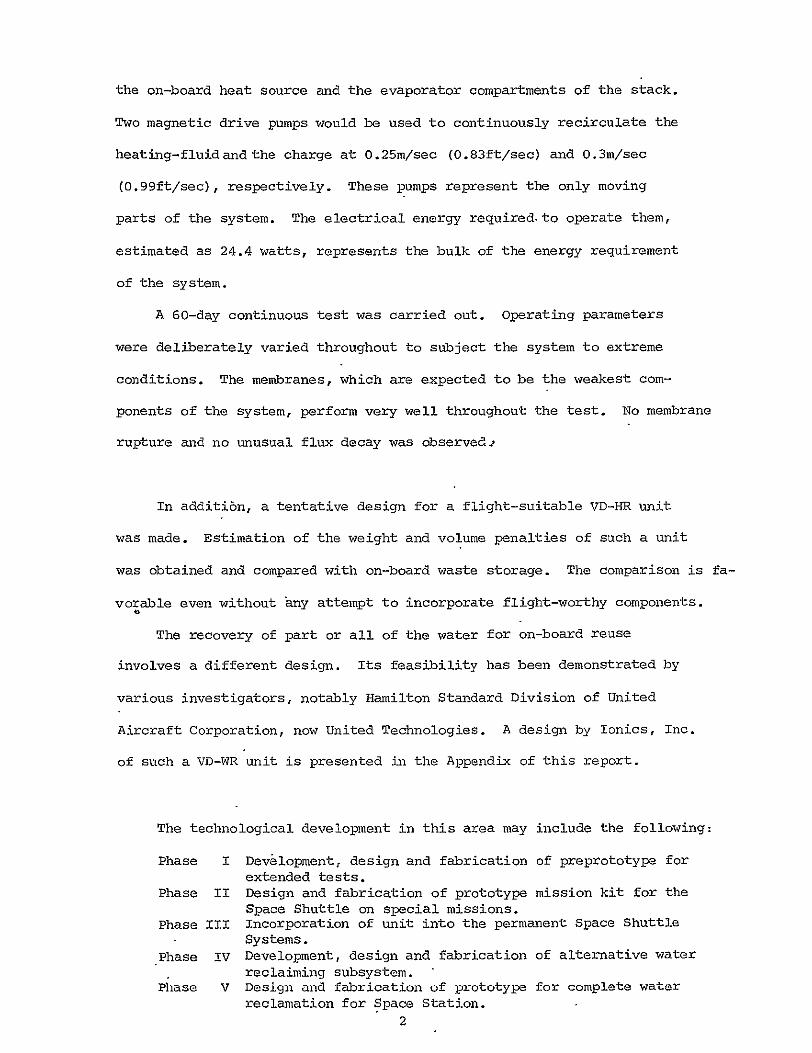

10
6
7shy
26- A
HH
Charge-Wastewater
Flow=002 9m3min
SII __ _ __ _ _
0029 0030 0031 0032 0033
Reciprocal Temperature A1K
Figure 8 FLUX AS A FUNCTION OF TEMPERATURE
22
The maximum temperature for the evaporator is probably restricted
by the temperature level of accessible on-board heat source It is
expected that the Freon cooling loop from the fuel cells can provide
sufficient heat at a temperature of 333-3470 K (145-165 0F) An efficient
heat exchange component can probably maintain the evaporator temperature
in the 331-341degK (140-155degF) range for VDR application
In-stack heat-exchange between the heating-fluid and the charge
depends on the minimization of the major resistance to heat transfer
which lies in the fluid films the relatively stagnant boundary layers
formed at both surfaces of the conductive metal plate Turbulent flow
within the charge compartment is required to minimize the effects of
concentration polarization at the charge-membrane interface Turbulent
flow within the heating fluid compartments needed investigation
Experiments showed that a heating-fluid velocity of 025msec (083ftsec)
Corresponding- to a Reynolds Numer of 2050 was sufficient to maintain
an evaporator temperature of 331-3410K (140-155F) This assumed that
water was the heating-fluid and flat titanium plates were used as the
conductive media and that the on-board beat source was at a temperature
of 333-3470K (145-1650F) and of sufficient flow The actual heating
capacity of the on-board heat source is not-known at this time It is
desirable to incorporate an electric heater into the system to provide
additional heat energy when required so that the performance of the VDR
is not completely dependent on the heat source
B Charge Flow Rate
In any selective mass transfer system a boundary layer effect exists
at the liquid-membrane interface This layer has a disproportionately
high concentration of low-permeability constituents and is relatively
stagnant It represents resistance to mass transfer from the bulk
solution to the membrane The thickness of the boundary layer can be
decreased by promoting turbulent flow at the interface
23
The plot of water flux as a function of charge velocity is shown in
Figure 9 Flux varies as the 042 power of the velocity up to a velocity
of 018msec (06Oftsec) beyond which increments in velocity lead to
progressively smaller increments in flux Above a velocity of 030msec
(99ftsec) any increase in charge velocity has negligible effect on
water flux A charge velocity of 030msec (99ftsec) was selected as
the desired charge velocity
It was experimentally determined that water flux is also a function
of the thickness of the charge spacer and the spacer design A decrease
in spacer thickness leads to an increase in pressure drop A few spacer
designs were investigated Mixing appears to be maximum using a design
as shown in Figure 10 This is based on the observation of flux behavior
as well as the deposition of precipitate on the membrane surface as charge
velocity is decreased The final selection is a three-ply laminate with
bridges on every ply to enhance mixing The bridges on each ply are
off-set so as to permit flow through the spacer With this particular
spacer design and a charge velocity of 030msec (99ftsec) the desired
flux was obtained A plot of water flux as a function of charge flow
using this new spacer design is shown in Figure 11
C Membrane Selection
The driving force in the VD-WR system is the water vapor pressure
gradient established between the hot evaporator and the cold condenser
Diffusion through the gap is impeded by the presence of noncondensables
and the boundary layer Occasional purging of noncondensables and the
creation of forced convection (natural convection being impossible under
zero-gravity environment) are essential to avoid flux decay The use of
a vacuum pump (or space vacuum) as a mechanical means of vapor removal is
very effective in that the impedance to diffusion is practically eliminated
At high vacuum low vapor pressure charge constituents that permeate the
I5p
A A
I09 A A
NN
Charge=wastewater 2
5 (101bft -hr) Temperature=333degK (145degF) Distillate Pressure =
1 megapascal (06 in Hg)
z I I I I 0 008 01 02 03 -0q 05
Charge Velocity msec
Figure 9 FLUX AS A FUNCTION OF CHARGE VELOCITY
25
Center Strip to Split Charge Stream Charge
to Enhance Mixing
bullto P-Comote -Mass Transfer Vl VIIA
eI
rid 1l 1J 1i
Sa
X 1iI 1111A
M t
1111A 1l 1111A
ChaBriges~ Into
MasseOTransfe
uri0TO V 1EOyHAGESPCERILUS AA
ISo - Liui Chrg Spomote Material
OPVEWO1CjA~ IL[U7ATINGA 17 V
0 -- _DA-
26lt
I
LAMINAR FLOW
REGION
TURBULENT FLOW
REGION 0
10 -
0 E
000 I-
N
(10Olhft_-hr) ____
rr
~emaratLure =333degK
Abull (145degF )
Hluman urine i 0 Washwater
27H
00 Charge Flow m min
Figure ll FLUX AS A FUNCTION OF CHARGE FLOW RATE
27
membrane are immediately evaporated The major resistance to mass transfer
appears to be the-charge-membrane interface (See previous section on the
variation of water flux with charge flow rate) At high charge flow rates
this boundary layer is minimized and the vapor diffusion through the
membrane becomes the rate determining factor This diffusion rate is
a function of charge temperature and composition and is characteristic
of a particular membrane Since the charge composition is an independent
variable and the charge temperature is defined by the temperature of the
on-board heat source the selection of the membrane phase-separator is a
very important task
Ideally the membrane should be highly permeable to water vapor and
nonpermeable to wastewater solutes It should have a minimum thickness
and yet high strength and integrity to minimize the possibility ofshy
meiwbrane rupture
Several membrane selection studies have been conducted by various
investigators over the years The results from the early work performed
under NAS2-7651 showed that many commercially available membranes for
reverse osmosis application perform satisfactorily in terms of water flux
and selectivity
The best candidate is a cellulose acetate asymmetric membrane
commercially produced by Envirogenics System Company of El Monte
California for reverse osmosis application This membrane is also
available cast on a polypropylene cloth to improve membrane strength
and integrity This membrane is recommended for application in the
system It has withstood several extended tests satisfactorily The
major problem associated with this membrane is its requirement of wet
storage
D Distillate Pressure
The impedance to vapor diffusion can be eliminated by using a vacuum
28
pump (or space vacuum) to mechanically remove permeated vapors However
ultra high vacuum (such as space vacuum) will cause instantaneous
evaporation and freezing of the water vapor This may physically plug
up valves and pipes As such it is desirable to control the rate of
over-board venting
The effects of operating vacuum on the water flux of the VDR
warrant investigation An experiment was conducted to study this
Figure 12 is a plot of water flux as a function of distillate absolute
pressure The latter was controlled by bleeding air through a needle
valve at different rates As noted from the plot over the range of
2-135 megapascal (058-42 inches of mercury) the impedance to vapor
diffusion is eliminated and the vapor diffusion through the gap is not
the rate determining factor confirming previous observations
Above 135 megapascals (42 inch H1g) the water flux drops rapidly
with increasing distillate pressure because of the accompanying increase
in impedance to diffusion At an absolute pressure of 213 megapascals
(64 in flg) the flux is negligible The total impedance to diffusion
becomes the controlling factor
The range that is most applicable to the VD-HR because of the ultra
high vacuum of outer space is the 0-2 megapascal range shown in the
Figure Although ultra high vacuum is not achievable by means of the
vacuum pump it can be noted that within this small pressure range
flux increases with decreasing pressure (increasing vacuum) The
actual flux in ultra high vacuum is therefore not known neither
is the extent of any adverse effects
29
o
10
H2 r -5 (101bft -hr)
Temp=331 K (140degF)i 3
Charge Flow=0029mmin (75 galmn
0 10 20 30 -0
Vacuum Compartment Pressure megapascal
Figure 12 FLUX AS A FUNCTION OF VACU C0MPARTMENT PESSURE
30
Task 3 Distillate Quality Studies
Although the permeated water need not meet potability standards for
VD-HR application it was desirable to monitor the quality of the distillate
for several reasons Permeated solutes may plug up the membrane surface
and the piping and valves that connect the vacuum compartments to
space vacuum The permeated solutes may interfere with spacecraft
instruments and experiments It may become necessary to recover a
portion of the permeated water for reuse if the on-board water supply
from the fuel cells becomes inadequate for astronaut usage
During the various tests the permeated condensables were routinely
collected to monitor product water quality It is noted that the highly
volatile constituents were collected in the condensate only to the extent
of their solubility in water at the condensate temperature Some
volatile noncondensables were lost in the vacuum pump trap and were not
recovered for assay purposes because of the difficulty in the entrapment
and recovery of these constituents Furthermore they are mostly
volatile organics and the spacecraft baseline systems such as the
feces inactivation unit already vent volatile organics and their
interference with instruments and experiments is expected to be
negligible
Table I shows the typical range of the contaminants present in the
condensate samples and compares them to the potability standard of the
United States Public Health Service Post-treatment with activated
charcoal and ion exchange resin will be needed to remove the residual
organics andammonia respectively if it becomes necessary to recover
the water to mnet the astronauts requirements In the case of overboa=1
venting the residual materials may interfere with spacecraft 6quipment
and experiments or they may plug up the piping and valves connecting the
system to space vacuum However these are outside the scope of the
present program 31
TABLE I COMPARISON OF PRODUCT VATER CONTAMINATION
WITH ESTABLISIED POTABILITY STANDARDS
(The samples have not been post-treated with charcoal or ion-exchange resin)
Sample Cotaminants (mgg)
Total Solids 250--300
Total Nitrogen 80-130
Ammonia Nitrogen 60-90
C 0 D 150-250
pH 8-95
LAS 5-10
Sodium 10-30
Potassium 5-10
Calcium 5-15
Magnesium 5-15
Zinc 0
Iron 0
Copper 0
Chloride 20-40
Sulfate 5-10
Phosphate 5-10
Turbidity 7
Odor Strong Obnoxious
SSD-NAS Limits (mgf)
1000
NS
NS
200
NS
NS
200
100
NS
150
NS
NS
30
450
250
150
NS
NS
USPHS WHO Limits Limits (rgo) (mg)
500 500
NS NS
NS NS
NS NS
65-85 7-85
NS NS
200 NS
100 NS
NS 75
120 50
5 5
03 03
10 10
250 200
250 200
100 NS
1 5
3 NS
Turbidity units
32
Task 4 Membrane Life Studies
The life and structural integrity of the membrane phase-separator
is a most crucial factor in any VD-WR process Membrane failure
represents a most important mode of system failure in terms of its
seriousness and its likelihood of occurrence It usually causes
interruption of the whole process and may call for actual repair work
Several prolonged tests have been conducted to investigate the
modes of membrane failure Although the cellulose acetate membrane is
susceptible to hydrolysis and rupture under extreme conditions suchshy
failure was not observed In these tests the membrane was subjected
to widely varied operating conditions that are not expected to occur
in normal VD-HR application such as abrupt changes in charge composition
and temperatures and repeated switching of the charge pump and vacuum
pump from an off positon to a highposition
However membrane fouling was usually observed Previous data
has indicated that the accompanying flux decline was more severe at
elevated temperatures high solute concentrations and low charge
velocities for a given membrane and was more severe for highly
hydropbilic membranes More significantly the rate of flux decline
was observed to decrease with operation time -- membrane became stabilized
after the initial hundred hours
Figure 13 summarizes a 60-day continuous test performed under the
contract The top section of the graph shows the water flux andthe
bottom section shows the changes in some of the operating conditions
namely the charge concentration and the charge temperature The charge
velocity pH level and the distillate pressure were also deliberately
altered from time to time The purpose for this variation in operating
33
Figure 13 DATA FROM MEMBRANE LIFE STUDIES
C 0
charge concentration0
10 1 -- - Charge temperature
~3[0
a~
E
0 10 20 30 210 so GO Operating Time days
34
conditions is two fold -- to obtain additional flux data as a function
of the particular independent variable and to subject the membrane to
unusually strenuous operating conditions No membrane rupture was
observed throughout the test
Figure 14 shows the product quality in terms of total residue
total chemical oxidation demand and total ammonia nitrogen under the
same operating conditions As can be noted from Figures 13 and 14 the
flux and product quality became stabilized after the initial decline
All data in this report is based on such a stabilized flux
The same membranes were used in subsequent tests including another
20-day continuous run The same stability in water flux and product
quality was observed
35
Figure 14 DISTILLATE QUALITY FROM MEMBRANE LIFE
(See Figure13 for Operating Conditions)
STUDIES
200 E
200shy o100 -
i2OO
O0 0shy
11
6004
(A
0
90shy0-
S 0 0 20 30 O 50 60
Operating Time days
Task 5 Additional Studies
A SoapDetergent Studies
Although the comparison study of soaps and detergents was not
included in the original program plan the need arose during the course
of using the soap recommended by NASA namely Olive Leaf of Palmetto
as manufactured by Rochester Germicide Corp During testing using a
combined urine-washwater charge severe flux decay was observed At the
same time the turbidity of the charge and the condensate also increased
Further investigation showed that the soap became hydrolyzed leaving a dark
yellow oily slime on the membrane surface and a white precipitate in the
wastewater charge It was confirmed later that the soap became destabilized
at the 330-3410K (140-1550F) temperature range at pH levels below 65
The precipitate and slime formation occurred only at charge solute weight
fraction exceeding 020 Since this condition is unavoidablein Vapor
Diffussion operation a different soap is needed
A total of 18 different liquid soaps and detergents were obtained
from their respective manufacturers Their properties are shown in
Table II In addition theirstability in the presence of concentrated
wastewater (025 solute weight fraction) was examined by refluxing the
soap-wastewater mixture at 330-3410K (140-155degF) for a period of 48
hours Since these were all commercial hand soaps their compatibility
with the human skin was assumed
Out of the 18 soaps and detergents two candidates were selected
as the most stable ones and tested in a five-day continuous run in
the test unit No excessive foaming precipitation clouding
of the condensate or any other adverse effect was noted at any
time A subsequent sixty-day continuous test using one of these
detergents the Sulframin 1260 Slurry by Witco Chemical Corporashy
tion confirms the suitability of the detergent for VDR application
The main ingredient of this formulation is sodium dodecyl benzene
Table I SoapsDetergent Studies
Active Surfactants ADDITIVES
Name Manufacturer Solids Type Emollient Perfume Dye pH Stability
1 Palmetto Rochester Germ Co 20 K coconut oils yes yes yes 100 PH
2 Royal Crest Rochester Germ Co 20 K coconut oils yes yes yes 99 PH
3 Miranol JEM Miranol Chem Co Amphoteric no no yes 103 S
4 Opal Lemon 540 Murphy-Phoenix Co 15-40 K coconut oils yes yes yes 106 S
5 Coco-Castile S amp E Chem Co 15-40 K coconut oils 92 PH
6 Germa Medica Huntington Labs Inc 40 K vegetable oils a lot yes yes 93 S
7 Liqua San C Huntington Labs Inc 40 K vegetable oils little yes yes 94 NT
8 Blandite Lester Labs Inc 30 Na coconut oil yes yes yes 90 E
9 Amazon 15 Trio Chem Works Inc 15 Na vegetable oil yes yes yes 96 P
10 Coco-Castile RTU Essential Chem Corp 15-40 K coconut oil yes yes yes 95 P
11 Ever Kleer Essential Chem Corp 40 K coconut oil yes yes 101 NT
12 Antiseptic Essential Chem Corp 20 K coconut oil yes yes yes 98 NT
13 Miranol C2M Miranol Chem Corp 40 Amphoteazic no no yes 82 S
14 Essanee S amp E Chem Co 15-40 NK yes yes yes 82 E
15 Sulframin i260 Witco Chem Corp 40 Nadodecyl sulfonate yes no yes 70 S
16 Basic H Shaklee Products 15 NK no nO yes 60 S
17 Neutrafoam S amp E Chem Co 15-40 NK yes no yes 68 PH
18 Emulso Emulso Corp 18 Na alky benzene yes yes yes 65 S
sulfonate
NK = not known manufacturer would not disclose
Stability refers to the stability of a 15 dilution of the soap in water added to an equal amount of a 40 NaCIshy
10 urea solution The solution is refluxed at 165 0F for 48 hours P=precipitation occurs H=soap appears-to hydrolyze
into an oily material usually fluffy in texture S=stable ie no change E=emulsification appears to have occured-no
solid formed but an oil phase appears at the bottom NT=not tested
sulfonate which may be assayed by the methylene blue indophenol method
for anionic surfactants
The other candidate found suitable for VDR application is Miranol
JEM a product of Miranol Chemical Company of which the main constituent
is an amphoteric imidazoline sulfonate
B Material Balance in the Unit
An experiment was designed to investigate the material balance in the
unit The main reason for performing this is that previous data showed
that nonvolatile species such as sodium chloride and urea permeated the
membranes These species might build up on the vapor-side of the
membrane and lower the overall flux or plug up the lines and valves
on this side of the membrane In actual experiments the performance
of the VD-WR as a whole has never been seriously interrupted However
on disassembling the unit solutes were actually observed to have
accumulated on the vapor-side of the membrane surface It was concluded
that a build-up of permeated nonvolatiles occurred initially but the
membrane soon reached steady state at a nonvolatile concentration below
saturation at which back diffusion would transport nonvolatiles back to
the charge Thus the system was tested 50 days without serious intershy
ference both in terms of flux and distillate quality
The system was charged with a 12-liter batch of human urine The
volume and amounts of the various major components were measured The
charge subsystem was carefully enclosed to prevent any loss due to
evaporation or spillage The unit was run continuously and the distillate
was collected in two 8-liter flasks and the volatiles were entrapped in a
series of cold traps containing boric acid solution at below 250 F
(maintained with a NaCl-ice mixture) the exact volume and concentration
of the acid solution having been premeasured After about 10-liters of
the liquid had been removed from the charge the system was shut off and
39
the amount and contents of the charge distillate and the boric-acid-trap
solution were all carefully measured and shown in Table III
From Table III a few observations may be made
(a) About 88 of the permeated water was condensed ie the flux values reported in this and the previous report were lower than the actual by some 12
(b) Some 6 of the NaCl was probably entrapped in the membrane interstices the vapor-side of the membrane surface and or the vacuum chamber fabric
(c) Amount of urea in the charge had dropped by 165 partly due to entrapment as suggested in (b) and partly due to previously reported observation that some urea was converted to NH HCO and (NH ) do and is no longer
4 3 4 23detectable by t~e urea assay
(d) Because of (c) a discrepancy in the level of ammonia nitrogen is noted Although appreciable amounts of ammonia N permeated the membranes and were absorbed by the acid traps some ammonia N was generated in the charge due to urea decomposition There is thus an overall
gain in the total ammonia N
(e) Overall about 8 of the total nonvolatiles permeated through the membrane most of which was entrapped as suggested in (b) and
(f) Volatiles also permeated through the membranes and some of these are trapped by the boric acid solution notably ammonia the remainder being removed from the system by the vacuum pump
40
TABLE III MATERIAL BALANCE EXPERIMENT
1 Mass Balance (gm)
Charge
Distillate
Acid-traps
Total
2 NaCl Balance (gm)
Charge Distillate Acid traps
Total
3 Urea Balance (gin)
Charge Distillate
Acid traps
Total
4 Ammonia N (gm)
Charge Distillate Acid traps
Total
5 Total Nonvolatiles
Charge Distillate Acid traps
Total
(gm)
Initial
1220
0
100
1320
1032 0 0
1032
2346 0
0
2346
178 0 0
178
3983
0 0
3983
Final Change (loss)
193
814
157
1164 (123)
964 (659) 049 0
9689 (606)
1960 (165) 108
008
19716 (159)
153 (140) 072 484
2086 + 172
3658 (816) 214 173
37524 (579)
41
Task 6 Fabrication and Testing of the Skid-Mount Unit
In the course of contract NAS2-7651 several improvements were made
on the HSD unit In addition VD-HR concept is a significant departure
from the basic VD-WR unit built by HSD In order to allow further tests
tobe conducted in this area outside of Ionics Incorporated a skidshy
mount unit was designed and fabricated as shown in Figure 15
The skid-mount unit is essentially the same as the bench unit
except for the replacement of glass components and plastic tubings of the
latter with suitable stainless steel components and tubings In order to
maintain cost at a minimum no attempt has been made to decrease the size
and weight of the components used The components have been located
farther apart than they needed to be to allow easy access and flexibility
for modification Any work to make the unit flight suitable is outside
the scope of the present program which is investigatory in nature
For clearer presentation the system is divided into three subshy
systems - the main loop or the charge loop the heating loop and the
waler recovery loop- as shown in Figures 16 17 and 18 respectively
In a flight-suitable unit the heating loop will be replaced with the
on-board Freon loop and the water recovery loop will be replaced by
the interfacing connection to space vacuum
As shown in Figure 16 the charge is pumped from its reservoir
through a filter cartridge which may be bypassed depending on the expershy
iment involved through a control valve and through the charge spacers
vithin the stack and returned to the reservoir and continuously circulated
until batch treatment is completed Charge flow rate and pressure are
shown on the display panel Temperature indicators at the stack show the
charge inlet and outlet temperatures
Figure 17 shows the heating-fluid loop consisting of a constant
42
- IA4bull
Figure 15 Back View of The Skid-Mount Unit
w bshy
-4shy
Figl6re16 PARTIAL DIAGRAM SHOWING TI CHARGE LOOP
TOP
VIEW N
- 6
LEGEND
0(D VDR Stack
Charge Stream Flowmeter amp Gauge
Particulate Prefilter
I
I
y
amp I
0 I
Charge
Charge Pump
Charge Reservoir
Hot-Fluid Return Line
Charge Return Line
in-coming Line
Hot-Fluid Incoming Line
I I Vacuum Line
FRONT 0
SCALE 1 2
VIEW
0 FIGURE I PARTIAL DIAGRAM SHOWIN
TH HOT-FLUID LOOP
TOP A LEGEND
V IE W ID - - i- SI Il- __ vDR stackregF -] -Hot-Fluid- - t Return LineI _
I 20 Charge Return LineL - - - -gt
-- - Charge Incoming Line
Vacuum Line
0--42 Display Panel
J Cooling-water Incoming Line
Hot-fluid Flowmeter
I Hot-fluid Pump
20- Constant Temperature Bath
O Hot-fluid Level Control
L J 0I 2 FRONT _ a VIEW SCALE
16
temperature bath equipped with a float that allows the in-flow of tap
water to replenish any water loss due to evaporation The heating-fluid
pump recirculates the hot water through a control valve the heating-fluid
spacers in the stack and the temperature bath Heating-fluid flow is
also shown in the display panel Temperature indicators at the stack
show the heating-fluid inlet and outlet temperatures
Figure 18 shows how the permeated water vapor is constantly being
removed from the stack A vacuum pump removes the water vapor which
passes through a tap-water-cooled condenser and is collected in a
reservoir by gravity A molecular seive trap located between the pump
and the collector prevents the back flow of oil into the collector and
reduces water vapor contamination of the vacuum oil The distillate
pressure is displayed in the panel The subsystem is needed to collect
the distillate so that its flux and quality can be monitored whenever
necessary
The total system was assembled and tested with a combined washwater
urine charge for 14 days continuously Fresh wastewater is added
periodically and distillate is removed at the same time The data colshy
lected is shown in Figure 19 At the end of the 14th day 94 of the water
had been removed from the wastewater representing the total washwater
urine output of a crew of 4 astronauts The operating conditions are
listed below
Charge flow = 0029m3min (075 gpm) Charge inlet temperature = 330K (135F) Charge outlet temperature = 331 0K (1370F) Charge pressure = 41 megapascal (6psi) Heating-fluid flow = 0038m3min (100 gpm) Heating-fluid inlet temp = 341 0K (155cr) Heating-fluid outlet temp = 331 0K (1400F) Distillate absolute pressure = ll-21(megapascal 02 to 04 psi) Pretreatment or prefiltration = none Soapdetergent used = Witco Chemical Company Sulframin
1260 slurry Membrane area = 0176m2 (191 ft2 )
46
7 FIGURE -218 PARTIAL DIAGRAM
SHOWING THE LOOP VACUUM
TOP I- - I
I ~ _ __j-~-LEGEND
Ni
E
VIEW I 0 VDR Stack
Y A reg Hot-Fluid Return Line
Sr Ir Charge Return Line
LampLNA Charge Incoming Line
Hot Fluid Incoming Line
Condenser
Distillate collector
Cold Trap
S Vacuum Pump
-- Cooling Water Incoming Line
Cooling Water Drain Line
0
SCALE
VIEW
Figure 19 ACCEPTANCE TEST DATA FOR SKID-MOUNT UNIT
A Average Cumulative Flux Temp=336deg K(150OF) Charge Flow=0029msec(75 gpm)
E3 Point Flux 3 Flux after 2-hr water-flush
S10-A
__0 ____ 0O_ C3
o00 0H 0 20$o300 - o- 0o 0 - o UU)
0) 01-0 o
1 100 -- 0 - 0 w O I - IO I I I 0
0 0 0 0 0 2 G 8 10 12 A
Operation Timer days
TABLE IV SUMMARY OF ACCEPTANCE TEST DATA FOR SKID-MOUNT UNIT
Total Charge Total Amount Average Time Volume Total Volume Water Point Cumulative
Elapsed Charged Residue Permegtqd Removed - Flu F (days) (Xi0- m3 ) (jw) (XlO m ) ( by vol) (kg-hr) (kgm -hr)
1 30 28 15 50 103 114
2 45 44 28 62 92 106
33 58 59 39 67 79 99
4 69 72 49 71 75 98
5 79 86 57 72 59 91
6 87 98 64 74 54 87
7 94 112 71 76 52 83
8 100 129 765 765 50 80
9 i00 144 815 815 45 76
10 100 167 86 86 37 75
11 100 248 90 90 32 71
12 100 307 935 935 27 71
13 100 392 955 955 18 67
14 i00 445 96 96 18 ---
NB Charged with 34 urine-washwater combined waste up to 30 x 10-6m3 (30shyliters ) mark daily for the first eight days No charge added after eighth day
Flux taken each morning before adding fresh charge
System shut off overnight due to insufficient charge
49
VI SYSTEM EVALUATION
A System Design
The operating parameters for a VD-HR system have been defined in the
previous section Several improvements over the HSD unit have been
incorporated into a nonflight-worthy skid-mount unit To meet flight
worthiness the various components on the unit will have to be-replaced
with lighter and smaller components without sacrificing system reliability
and safety Components will also have to be repositioned to minimize
occupied space Electrically operated valves sensors and switches are
needed to minimize in-flight handling of the system by the astronauts
The heating-fluid loop will be replaced by the required interfacing with
on-board cooling loop The condensing-collection subsystem and the
vacuum trap and vacuum pump will be replaced by the interfacing connecshy
tion with space vacuum
In addition spare parts may be added in-line to reduce on-board
replacement of failing components and increase system reliability
Figure 19 is an example of a VDR design for continuous automatic operashy
tion The wastewater is collected in a separate waste collection system
and stored in a spring-loaded collapsible reservoir When a particular
volume is exceeded a switch activates solenoid valve SV and the
wastewater is squeezed into the batch treatment reservoir until it is
filled At this point another switch activates the three-way solenoid
valves SV1 and SV2 such that the wastewater charge is continuously
circulated around the loop SV1-SV2--CRP At the same time the heatingshy
fluid pump is activated to bring the on-board excess heat to the VD-WR
stack where heat exchange occurs through conductive metal plates SV3
is then activated and the distillate compartments are connected to
space vacuum
To increase system reliability spare permeation cells may be added
SOLID
WASTE
DISPOSAL SYSTEM
TO k$SBLINE RADIATORS
L S
WASTECOLLECTION I I _ _
INTERFACE w T
sYsTEM [ STACKTSPACE
S2VACUUM
WASTE TCH
TREATMEN4 - -LEGEND
CSI CS =Conductivity Sensors
SSV 2 SV =Solenoid Vavles
RESERVOI U FCRPChage
CSERVOILL 2 3 Recirculation Pump
SV
Figure 20 VD-WR System for Waste Rejection On-Board Space Shuttle
to the VDR stack and connected to the primary cells Wastewater charge
is recirculated only through the primary cells although the heating-fluid
may be recirculated through all the cells Likewise only primary cells
-are connected to space vacuum Such a stack will require external
manifolds equippedwith solenoid valves and sensors AIf malfunction occurs
leading to condensate contamination the sensor will shut off the solenoid
valve in the relevant vacuum compartment as well as the charge inlet
solenoid valves belonging to the same cell This in turn sends a
signal to the control panel and the charge and condensate solenoid valves
of a spare cell will be activated and it will become part of the primary
stack Six spare cells may be included in the stack to form a 10-cell
stack The actual number of cells needed depends on the desired level
of reliability and will have to be empirically determined
The individual cell is equipped with its own sensor and solenoid
valves These sensors and valves shouldprevent any leaked charge from
reaching SV Additional sensors and valves may be added depending on
the desired reliability and safety standard
If no malfunction occurs waste treatment will continue until the
solute weight fraction of the charge reaches 040 a level corresponding
to 95 percent water removal efficiency At this point the conductivity
sensor CS1 shuts off valves SV and SV and diverts the flow through SV21 1 32
such that the waste concentrate is pumped to the solid waste treatment
system When this is completed SV2 is shut off SV1 is activated and
the next batch of wastewater is introduced and treated
52
B System Efficiency
The efficiency of the VD-WR system for treating human urine has
been repeatedly demonstrated Long duration tests included HSDs 54-day
uninterrupted test in 1966 in which 95 percent of the water was recovered
a shorter test with prefiltration where 98 percent of the water was
recovered several 15-30 day tests by Gulf South and Amicon Company
in which 92 of the water was recovered and the 15-day test under this
program in which 94 of the water was recovered The system can readily
recover 95 of the water from wastewater a level required for a
completely ciosed-loop water system This represents a
20-fold volume reduction and a 15-fold weight reduction of the on-board
wastewater
C System Weight and Volume Penalties
The weight and occupied space of a VD-BR prototype are not known but
they can be estimated from known commercially available components
Table V lists the weights and volumes of presently obtainable non-flight comshy
poents These represent the maximum values Actual values for an on-board unit
will be significantly less Component weight and volume reduction can be
achieved by a) conducting a comprehensive search of commercially available
items b) stripping the items of all nonessential parts and c) incorporashy
tion of special components made available by space technology
From Table v the maximum system weight is calculated to be 647kg
(1421b) fixed weight No expendable will be needed The system
occupied space is similarly calculated to be 0678m3(4140 in3) Taking
into account wasted space between some components the VDR unit is
expected to fit into a box of 036m x 036m x 076m (14in x 14in x 30in)
With the application of the aforementioned reduction techniques these
values can be decreased by an estimated 30
Comparison of these values with the on-board waste storage may be
made Assuming zin average crew of four astronauts the daily amount of 53
of urine produced is 0006m 3 (158 gal) and the daily amount of washwater
is 0008m3 (211 gal) For an average mission duration of 14 days the
total wastewater produced is 0196m3 (518 gal) The corresponding
weight is 225kg (4961h) The application of VDR can reduce these values
to a maximum of 00Q98m 3(259gal) and 122kg--(2G691b) Adding these-to
the estimated maximum weight and volume penalties of the VDR the values
become 0108m3 (285ga1) and 769kg (1691b) respectively These compare
favorably with the weight and volume penalties of on-board storage -shy
45 space savings and 66 weight savings even if the weight and volume of
the storage tank is ignored
The calculations above refer to the re-entry weight and volume savings
The affect of the VD-HR on launch weight is different (Launch volume is
unaffected because cabin space must be provided for storing the wasteshy
water that will be produced through the course of the mission) At
launching the VD-HR will provide supplemental cooling resulting in a savings
if waste storage is intended Whether such an additional weight is
acgeptable may depend on various other factors not known to this investigshy
ator The VDR will provide supplemental cooling resulting in a savings
of baseline radiator weight which may be significant Additional weight
from waste storage at re-entry requires additional fuel which is carried
within the shuttle This difference may also be significant In addition
the accumulation of waste within the cabin may take up valuable space
which may not be acceptable
The contribution of the VD-HR unit will increase the advancement
in the technology involved It will also become more significant if
brew size or mission duration are increased since any increase in
the weight and volume penalties will be only a fraction of the correshy
sponding increase in waste storage weight and volume penalties
D Energy Requirement
The energy requirement of the VD-HR is equal to the pumping energy
required to operate the charge pump the heating fluid pump and the
conductivity sensors and solenoid valves Based on a charge flow of
300029mmin (7-gpm) and a heating-fluid flow of 0039 (lOgpm) and
corresponding pressure drops of 55 megapascal (8 psi) and 41 megapascal
(6 psi) respectively the total theoretical energy required to operate
the pumps is 146 watts Assuming a pump efficiency of 60 this becomes
244watts The energy required for the instruments is estimated as
10 watts The total power consumption of the VD-HR is then 344 watts
55
TABLE V SYSTEM FIXED WEIGHT AND VOLUME ENALTIES
(These are Non Flight Components)
SYSTEM COMPONENTS NUMBER NEEDED MAXIMUM WEIGHT MAXIMUM VOL M3
(include spares) Kg (ib) m3 x0 - 3 (in
1 Treatment Reservoir 2 91 (20) 1200 (732)
2 Charge Pump 2 50 (11) 368 (224)
3 Hot-fluid Pump i 25 (55) 184 (112)
4 Hot-fluid Tank 1 10 (22) 082 (50)
5 Permeation Cell 10 221 (48) 354 (2160)
6 Stack Frame 1 227 (50) 016 (10)
7 Charge Manifold 1 50 (11) 098 (60)
8 Vacuum Manifold 1 33 (73) 074 (45)
9 Valves 3 73 (16) 131 (80)
10 Sensors 3 15 (33) 164 (100)
1- Skid Frame 1 52 (11) 393 (240)
12 Panel 1 20 (44) 328 (200)
13 Piping amp Fittings 23 (51) 049 (30)
14 Central Relay 1 273 (60) 157 (96)
TOTAL 647 (142) 0978 (4149) Kg (Tb) m (in)
VII RECOMMENDATIONS FOR FUTURE STUDIES
2 Defining the need for the VD-HR
The feasibility of the VD-HR for Shuttle Application has been examined
All indications are that the system is feasible The immediate area for
future studies lies-In the examination of Shuttle Systems to define more
exactly the extent of the need or advantage of a waste-allevi4tion and
supplemental cooling unit Advantages of the VD-HR as opposed to alternative
means of waste-alleviation and provision of supplemental cooling should be
examined through a study of the alternative means
2 Feasibility Studies
It is concluded in this report that the feasibility of the VD-HR
lies in the interface with on-board heat source and with space vacuum
Future studies should examine these interfaces in detail Sufficient
confidence in the feasibility of such interfaces must precede the
fabrication of a prototype
3 Preprototype Design Studies
Material selection and component selection have been largely ignored
in the present program In preparation for a prototype a survey of
existing commercially available components should be made with emphasis
on minimum weight volume and energy penalties and on maximum life
reliability and safety Wherever feasible and necessary the components
should be stripped of nonessential parts or suitably modified The
design of a preprototype should be made based on these components
4 WaterReclamation Loop
The alternative of reclaiming part or all of the treated water for
reuse may be needed This could be an end in itself or it could be a
step towards a complete water reclamation system for use during missions
56
of extended duration The-design of this loop is outlined in the Appendix
Its development is another important area for future work
5 Design and Fabrication of Prototype
Eventually the design and fabrication of the prototype VD-HR v ith or
without the alternative water reclamation loop should be performed It
may be equally important to develop design and fabricate a VahWR with no
provision for over-board venting where the sole application is a completely
independent water reclamation system
57
VIII APPENDIX
An Alternative Loop for Water Reclamation
VD-WR for Water Reclamation
It may be desirable to recover the water separated from the waste-
The answer lies in the original VD-WR conceptwater for on-board usage
Figure 21 is a schematic diagram of such a system designed by Ionics Inc
Briefly the VD-WR stack calls for the substitution of the vacuum
compartments of the VD-HR stack with porous plate condensers Figure 22 is
a diagram of such a stack consisting of four normally operating cells and
six spare cells
As seen in Figure 22 cells 1 through 4 form the normal stack
The urine charge is recirculated only through these cells Each cell
is equipped with a conductivity sensor in the condensate line If a
malfunction occurs leading to condensate contamination the sensor will
be activated and the solenoid valves in the condensate as well as the
charge lines belonging to the same cell will be shut off This in
turn sends a signal to the control panel and the next cell in this case
cell 5 will be included in the new treatment stack by activating the
charge and condensate solenoid valves of cell 5
The condenser is formed by imbedding a cooling coil inside a sandwich
of two porous plates of suitable porosity This has been successfully
demonstrated by HSD The portion of the plates not exposed to the diffusshy
ing vapor is covered by a nonporous metal to form a condensing chamber as
shown in Figure 23 Water condenses at the cold porous plate and is held
within by surface tension A recirculating fan promotes forced convention
in the gap to reduce boundary layer resistance to vapor diffusion and
effectively moves the vapor by mixing from the membrane to the condenser
The accumulation of noncondensables inside the vapor gap is prevented by
CPP=Charge Recirculating Pump LS =Level Switch
FROM RF=Recirculating Fan SxV =Solenoid Valve WASTE hRP=Heating Fluid Recirculating Pump CV =Check Valve COLLECTION (-V=GAS Vent CS =Conductivity Sensor
SYSTEM TBP=TUBING PUMP SDoA=SURGE DAMPENING ACCUMULATOR
I SV
SV1
WASTEsToRAGE 7
RESERVOIR V
12 COOLING
T CATPOSTMENTP4SERVOTR VD-W R STACT
[ ]AU
1
N I T
SV 2 aSDA CAN ISTE E
CS1 ----- -shy-WASTE
POST TRTTATMENT
Ir r WASTE
SOLIDS -
HRP TREATMENT
L--------------HEAT LIR
Figure 21 VD-WR SYSTEM to
SYSTEM
RECLAIM THE PERMEATED WATER
PORTABLE WATER STORAGE RESERVOIR
CHARGE OUT
--- --- --- --- --- - CONDENSATE OUT
(3 CELLS OMITTED)
-~~ ~--7--
--- --- -- -- - RLAY BRIDGE
Figure22 --- -1 - --------POROUS PLATE F COOLING COIL
DIFFUSION GAP - - - - - -- - - - - -
RECIRCULATION VENT -__- -- -- - ---- -- -- -
M4EIRANE COOLINGI
CHARGE SPACER(2CLSOITDVAE
(2~IVT CELTIITD
I CHARGE IN
Figure 2 2 -A 10-CELL VJD-WR STACK
RECIRCULATIN4 rOUT
r-]AI
DEMBRANE
O
f ---- 7 o lt -- gt
lt
LI H VAPOR R
GAP--J-9
FROM CIRCULATINJ FAN
FROM4 OTHER CONDENSERS
COOLING COOLING TLUID [lFLUID
GAS i
- i POROUS PLATES
jW copy -- COOLING LOOP CTCoiling Perpendicular
I To The Surface of The Page) POTABLE
WATER WICKING RESERVOIR
o
I NON-POROUS S- METAL CAP
POSTCONDUCTIVITY SENSOR TREAT
CANIS
SOLENOIDi VALVE2
Pressurized CE
I - Air V2A
Diaphragmbull COMPRd
TUBIN(
~~
TUBINC WICKIG MAERIAPUMP
SURGE
DAMPENING ACCUMULATOR
C
means of a cabin vent through which the noncondensables some ammonia
and certain volatile organics diffuse
The condensate in the porous plate is removed through wicks
Conductivity sensors constantly monitor the quality of the product water
leaving the condenser A conductivity reading exceeding 1450 imhocm
approximately equivalent to a sodium chloride level of 1000 ppr indicates
cell malfunction When such a level is detected a signal is sent to the
central control panel which shuts off a solenoid valve a short distance
downstream and the charge inlet valve of the malfunction cell and switches
on the corresponding valves of the next spare cell This system of
installed spares effectively changes permeation cells without requiring
actual on-board maintenance by the astronauts
The condensate from all functioning cells is combined and picked up
by wicking The wick is contained jn flexible tubihg and the assembly is
passed through a tubing pump with an off-centered rotating cam The pump
pushes the condensate through post-treatment canisters through a check
vave into a spring-loaded collapsible reservoir An in-line accumulator
dampens the surging effect of the pump and together with the wick minimizes
any unusually large transient negative pressure effect on the porous-plate
condensers This effectively prevents gaseous material from being sucked
into the condensing assembly
National Aeronautics and Space Administration - N ASA Ames Research Moffett Field California 94035
Reply to Attn of NAS 2-7651 ATL202-3 September 21 1977
NASA Representative Scientific amp Technical Information Facility PO Box 8757 BaltimoreWashington International Airport Maryland 21240
Subject Transmittal of Contractor Report Water Vapor Diffusion Membrane Development final report Dated July 26 1977 by Michael K Tan lonics Incorporated 65 Grove Street Watertown Massachusetts 02172
Reference Program Code 199-73-02-11
--The s ct report prepared under Contract NAS 2-7651 has been revieweamp at es ended for release in STAR as CR-152037
lef Library Branch
Enclosure I cy subject report
cc NASA Hqrs Code KSI (wo encs)
SEP1SV11
9 EEWB
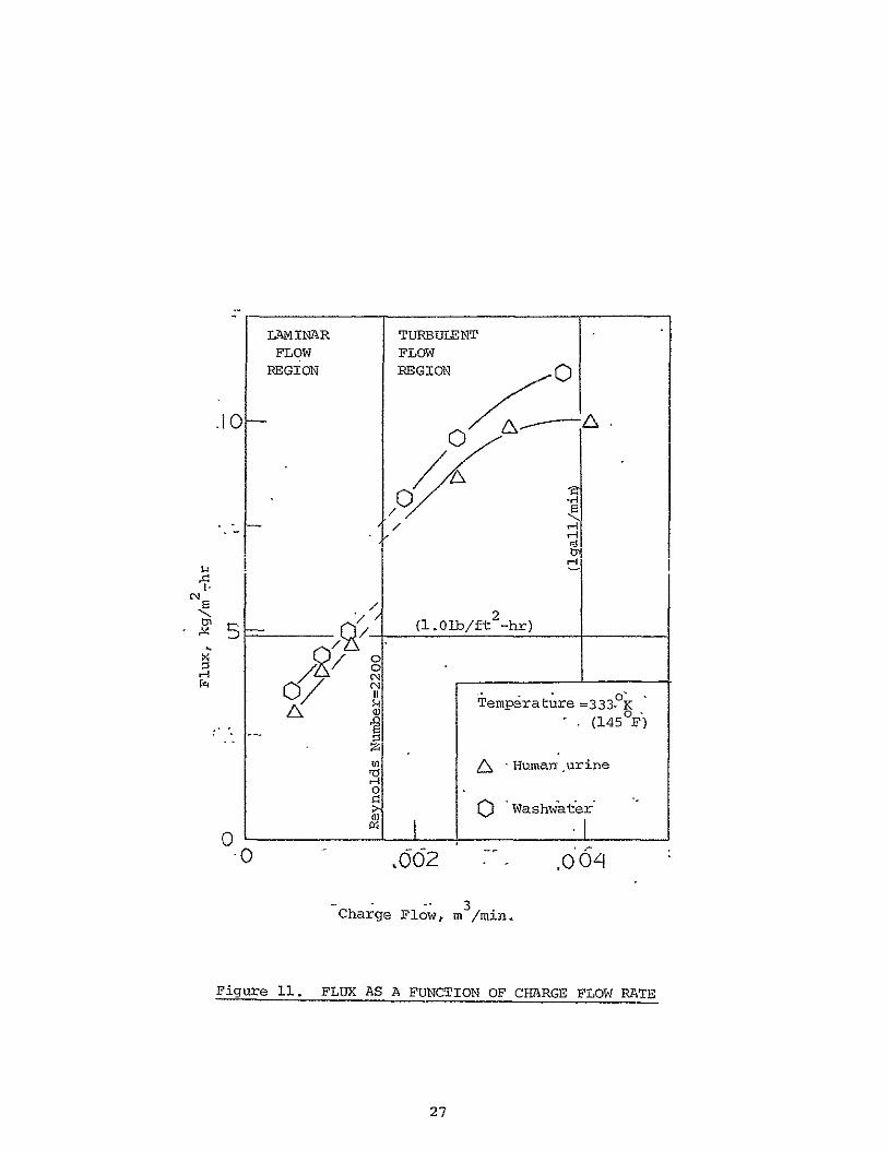

o
10
H2 r -5 (101bft -hr)
Temp=331 K (140degF)i 3
Charge Flow=0029mmin (75 galmn
0 10 20 30 -0
Vacuum Compartment Pressure megapascal
Figure 12 FLUX AS A FUNCTION OF VACU C0MPARTMENT PESSURE
30
Task 3 Distillate Quality Studies
Although the permeated water need not meet potability standards for
VD-HR application it was desirable to monitor the quality of the distillate
for several reasons Permeated solutes may plug up the membrane surface
and the piping and valves that connect the vacuum compartments to
space vacuum The permeated solutes may interfere with spacecraft
instruments and experiments It may become necessary to recover a
portion of the permeated water for reuse if the on-board water supply
from the fuel cells becomes inadequate for astronaut usage
During the various tests the permeated condensables were routinely
collected to monitor product water quality It is noted that the highly
volatile constituents were collected in the condensate only to the extent
of their solubility in water at the condensate temperature Some
volatile noncondensables were lost in the vacuum pump trap and were not
recovered for assay purposes because of the difficulty in the entrapment
and recovery of these constituents Furthermore they are mostly
volatile organics and the spacecraft baseline systems such as the
feces inactivation unit already vent volatile organics and their
interference with instruments and experiments is expected to be
negligible
Table I shows the typical range of the contaminants present in the
condensate samples and compares them to the potability standard of the
United States Public Health Service Post-treatment with activated
charcoal and ion exchange resin will be needed to remove the residual
organics andammonia respectively if it becomes necessary to recover
the water to mnet the astronauts requirements In the case of overboa=1
venting the residual materials may interfere with spacecraft 6quipment
and experiments or they may plug up the piping and valves connecting the
system to space vacuum However these are outside the scope of the
present program 31
TABLE I COMPARISON OF PRODUCT VATER CONTAMINATION
WITH ESTABLISIED POTABILITY STANDARDS
(The samples have not been post-treated with charcoal or ion-exchange resin)
Sample Cotaminants (mgg)
Total Solids 250--300
Total Nitrogen 80-130
Ammonia Nitrogen 60-90
C 0 D 150-250
pH 8-95
LAS 5-10
Sodium 10-30
Potassium 5-10
Calcium 5-15
Magnesium 5-15
Zinc 0
Iron 0
Copper 0
Chloride 20-40
Sulfate 5-10
Phosphate 5-10
Turbidity 7
Odor Strong Obnoxious
SSD-NAS Limits (mgf)
1000
NS
NS
200
NS
NS
200
100
NS
150
NS
NS
30
450
250
150
NS
NS
USPHS WHO Limits Limits (rgo) (mg)
500 500
NS NS
NS NS
NS NS
65-85 7-85
NS NS
200 NS
100 NS
NS 75
120 50
5 5
03 03
10 10
250 200
250 200
100 NS
1 5
3 NS
Turbidity units
32
Task 4 Membrane Life Studies
The life and structural integrity of the membrane phase-separator
is a most crucial factor in any VD-WR process Membrane failure
represents a most important mode of system failure in terms of its
seriousness and its likelihood of occurrence It usually causes
interruption of the whole process and may call for actual repair work
Several prolonged tests have been conducted to investigate the
modes of membrane failure Although the cellulose acetate membrane is
susceptible to hydrolysis and rupture under extreme conditions suchshy
failure was not observed In these tests the membrane was subjected
to widely varied operating conditions that are not expected to occur
in normal VD-HR application such as abrupt changes in charge composition
and temperatures and repeated switching of the charge pump and vacuum
pump from an off positon to a highposition
However membrane fouling was usually observed Previous data
has indicated that the accompanying flux decline was more severe at
elevated temperatures high solute concentrations and low charge
velocities for a given membrane and was more severe for highly
hydropbilic membranes More significantly the rate of flux decline
was observed to decrease with operation time -- membrane became stabilized
after the initial hundred hours
Figure 13 summarizes a 60-day continuous test performed under the
contract The top section of the graph shows the water flux andthe
bottom section shows the changes in some of the operating conditions
namely the charge concentration and the charge temperature The charge
velocity pH level and the distillate pressure were also deliberately
altered from time to time The purpose for this variation in operating
33
Figure 13 DATA FROM MEMBRANE LIFE STUDIES
C 0
charge concentration0
10 1 -- - Charge temperature
~3[0
a~
E
0 10 20 30 210 so GO Operating Time days
34
conditions is two fold -- to obtain additional flux data as a function
of the particular independent variable and to subject the membrane to
unusually strenuous operating conditions No membrane rupture was
observed throughout the test
Figure 14 shows the product quality in terms of total residue
total chemical oxidation demand and total ammonia nitrogen under the
same operating conditions As can be noted from Figures 13 and 14 the
flux and product quality became stabilized after the initial decline
All data in this report is based on such a stabilized flux
The same membranes were used in subsequent tests including another
20-day continuous run The same stability in water flux and product
quality was observed
35
Figure 14 DISTILLATE QUALITY FROM MEMBRANE LIFE
(See Figure13 for Operating Conditions)
STUDIES
200 E
200shy o100 -
i2OO
O0 0shy
11
6004
(A
0
90shy0-
S 0 0 20 30 O 50 60
Operating Time days
Task 5 Additional Studies
A SoapDetergent Studies
Although the comparison study of soaps and detergents was not
included in the original program plan the need arose during the course
of using the soap recommended by NASA namely Olive Leaf of Palmetto
as manufactured by Rochester Germicide Corp During testing using a
combined urine-washwater charge severe flux decay was observed At the
same time the turbidity of the charge and the condensate also increased
Further investigation showed that the soap became hydrolyzed leaving a dark
yellow oily slime on the membrane surface and a white precipitate in the
wastewater charge It was confirmed later that the soap became destabilized
at the 330-3410K (140-1550F) temperature range at pH levels below 65
The precipitate and slime formation occurred only at charge solute weight
fraction exceeding 020 Since this condition is unavoidablein Vapor
Diffussion operation a different soap is needed
A total of 18 different liquid soaps and detergents were obtained
from their respective manufacturers Their properties are shown in
Table II In addition theirstability in the presence of concentrated
wastewater (025 solute weight fraction) was examined by refluxing the
soap-wastewater mixture at 330-3410K (140-155degF) for a period of 48
hours Since these were all commercial hand soaps their compatibility
with the human skin was assumed
Out of the 18 soaps and detergents two candidates were selected
as the most stable ones and tested in a five-day continuous run in
the test unit No excessive foaming precipitation clouding
of the condensate or any other adverse effect was noted at any
time A subsequent sixty-day continuous test using one of these
detergents the Sulframin 1260 Slurry by Witco Chemical Corporashy
tion confirms the suitability of the detergent for VDR application
The main ingredient of this formulation is sodium dodecyl benzene
Table I SoapsDetergent Studies
Active Surfactants ADDITIVES
Name Manufacturer Solids Type Emollient Perfume Dye pH Stability
1 Palmetto Rochester Germ Co 20 K coconut oils yes yes yes 100 PH
2 Royal Crest Rochester Germ Co 20 K coconut oils yes yes yes 99 PH
3 Miranol JEM Miranol Chem Co Amphoteric no no yes 103 S
4 Opal Lemon 540 Murphy-Phoenix Co 15-40 K coconut oils yes yes yes 106 S
5 Coco-Castile S amp E Chem Co 15-40 K coconut oils 92 PH
6 Germa Medica Huntington Labs Inc 40 K vegetable oils a lot yes yes 93 S
7 Liqua San C Huntington Labs Inc 40 K vegetable oils little yes yes 94 NT
8 Blandite Lester Labs Inc 30 Na coconut oil yes yes yes 90 E
9 Amazon 15 Trio Chem Works Inc 15 Na vegetable oil yes yes yes 96 P
10 Coco-Castile RTU Essential Chem Corp 15-40 K coconut oil yes yes yes 95 P
11 Ever Kleer Essential Chem Corp 40 K coconut oil yes yes 101 NT
12 Antiseptic Essential Chem Corp 20 K coconut oil yes yes yes 98 NT
13 Miranol C2M Miranol Chem Corp 40 Amphoteazic no no yes 82 S
14 Essanee S amp E Chem Co 15-40 NK yes yes yes 82 E
15 Sulframin i260 Witco Chem Corp 40 Nadodecyl sulfonate yes no yes 70 S
16 Basic H Shaklee Products 15 NK no nO yes 60 S
17 Neutrafoam S amp E Chem Co 15-40 NK yes no yes 68 PH
18 Emulso Emulso Corp 18 Na alky benzene yes yes yes 65 S
sulfonate
NK = not known manufacturer would not disclose
Stability refers to the stability of a 15 dilution of the soap in water added to an equal amount of a 40 NaCIshy
10 urea solution The solution is refluxed at 165 0F for 48 hours P=precipitation occurs H=soap appears-to hydrolyze
into an oily material usually fluffy in texture S=stable ie no change E=emulsification appears to have occured-no
solid formed but an oil phase appears at the bottom NT=not tested
sulfonate which may be assayed by the methylene blue indophenol method
for anionic surfactants
The other candidate found suitable for VDR application is Miranol
JEM a product of Miranol Chemical Company of which the main constituent
is an amphoteric imidazoline sulfonate
B Material Balance in the Unit
An experiment was designed to investigate the material balance in the
unit The main reason for performing this is that previous data showed
that nonvolatile species such as sodium chloride and urea permeated the
membranes These species might build up on the vapor-side of the
membrane and lower the overall flux or plug up the lines and valves
on this side of the membrane In actual experiments the performance
of the VD-WR as a whole has never been seriously interrupted However
on disassembling the unit solutes were actually observed to have
accumulated on the vapor-side of the membrane surface It was concluded
that a build-up of permeated nonvolatiles occurred initially but the
membrane soon reached steady state at a nonvolatile concentration below
saturation at which back diffusion would transport nonvolatiles back to
the charge Thus the system was tested 50 days without serious intershy
ference both in terms of flux and distillate quality
The system was charged with a 12-liter batch of human urine The
volume and amounts of the various major components were measured The
charge subsystem was carefully enclosed to prevent any loss due to
evaporation or spillage The unit was run continuously and the distillate
was collected in two 8-liter flasks and the volatiles were entrapped in a
series of cold traps containing boric acid solution at below 250 F
(maintained with a NaCl-ice mixture) the exact volume and concentration
of the acid solution having been premeasured After about 10-liters of
the liquid had been removed from the charge the system was shut off and
39
the amount and contents of the charge distillate and the boric-acid-trap
solution were all carefully measured and shown in Table III
From Table III a few observations may be made
(a) About 88 of the permeated water was condensed ie the flux values reported in this and the previous report were lower than the actual by some 12
(b) Some 6 of the NaCl was probably entrapped in the membrane interstices the vapor-side of the membrane surface and or the vacuum chamber fabric
(c) Amount of urea in the charge had dropped by 165 partly due to entrapment as suggested in (b) and partly due to previously reported observation that some urea was converted to NH HCO and (NH ) do and is no longer
4 3 4 23detectable by t~e urea assay
(d) Because of (c) a discrepancy in the level of ammonia nitrogen is noted Although appreciable amounts of ammonia N permeated the membranes and were absorbed by the acid traps some ammonia N was generated in the charge due to urea decomposition There is thus an overall
gain in the total ammonia N
(e) Overall about 8 of the total nonvolatiles permeated through the membrane most of which was entrapped as suggested in (b) and
(f) Volatiles also permeated through the membranes and some of these are trapped by the boric acid solution notably ammonia the remainder being removed from the system by the vacuum pump
40
TABLE III MATERIAL BALANCE EXPERIMENT
1 Mass Balance (gm)
Charge
Distillate
Acid-traps
Total
2 NaCl Balance (gm)
Charge Distillate Acid traps
Total
3 Urea Balance (gin)
Charge Distillate
Acid traps
Total
4 Ammonia N (gm)
Charge Distillate Acid traps
Total
5 Total Nonvolatiles
Charge Distillate Acid traps
Total
(gm)
Initial
1220
0
100
1320
1032 0 0
1032
2346 0
0
2346
178 0 0
178
3983
0 0
3983
Final Change (loss)
193
814
157
1164 (123)
964 (659) 049 0
9689 (606)
1960 (165) 108
008
19716 (159)
153 (140) 072 484
2086 + 172
3658 (816) 214 173
37524 (579)
41
Task 6 Fabrication and Testing of the Skid-Mount Unit
In the course of contract NAS2-7651 several improvements were made
on the HSD unit In addition VD-HR concept is a significant departure
from the basic VD-WR unit built by HSD In order to allow further tests
tobe conducted in this area outside of Ionics Incorporated a skidshy
mount unit was designed and fabricated as shown in Figure 15
The skid-mount unit is essentially the same as the bench unit
except for the replacement of glass components and plastic tubings of the
latter with suitable stainless steel components and tubings In order to
maintain cost at a minimum no attempt has been made to decrease the size
and weight of the components used The components have been located
farther apart than they needed to be to allow easy access and flexibility
for modification Any work to make the unit flight suitable is outside
the scope of the present program which is investigatory in nature
For clearer presentation the system is divided into three subshy
systems - the main loop or the charge loop the heating loop and the
waler recovery loop- as shown in Figures 16 17 and 18 respectively
In a flight-suitable unit the heating loop will be replaced with the
on-board Freon loop and the water recovery loop will be replaced by
the interfacing connection to space vacuum
As shown in Figure 16 the charge is pumped from its reservoir
through a filter cartridge which may be bypassed depending on the expershy
iment involved through a control valve and through the charge spacers
vithin the stack and returned to the reservoir and continuously circulated
until batch treatment is completed Charge flow rate and pressure are
shown on the display panel Temperature indicators at the stack show the
charge inlet and outlet temperatures
Figure 17 shows the heating-fluid loop consisting of a constant
42
- IA4bull
Figure 15 Back View of The Skid-Mount Unit
w bshy
-4shy
Figl6re16 PARTIAL DIAGRAM SHOWING TI CHARGE LOOP
TOP
VIEW N
- 6
LEGEND
0(D VDR Stack
Charge Stream Flowmeter amp Gauge
Particulate Prefilter
I
I
y
amp I
0 I
Charge
Charge Pump
Charge Reservoir
Hot-Fluid Return Line
Charge Return Line
in-coming Line
Hot-Fluid Incoming Line
I I Vacuum Line
FRONT 0
SCALE 1 2
VIEW
0 FIGURE I PARTIAL DIAGRAM SHOWIN
TH HOT-FLUID LOOP
TOP A LEGEND
V IE W ID - - i- SI Il- __ vDR stackregF -] -Hot-Fluid- - t Return LineI _
I 20 Charge Return LineL - - - -gt
-- - Charge Incoming Line
Vacuum Line
0--42 Display Panel
J Cooling-water Incoming Line
Hot-fluid Flowmeter
I Hot-fluid Pump
20- Constant Temperature Bath
O Hot-fluid Level Control
L J 0I 2 FRONT _ a VIEW SCALE
16
temperature bath equipped with a float that allows the in-flow of tap
water to replenish any water loss due to evaporation The heating-fluid
pump recirculates the hot water through a control valve the heating-fluid
spacers in the stack and the temperature bath Heating-fluid flow is
also shown in the display panel Temperature indicators at the stack
show the heating-fluid inlet and outlet temperatures
Figure 18 shows how the permeated water vapor is constantly being
removed from the stack A vacuum pump removes the water vapor which
passes through a tap-water-cooled condenser and is collected in a
reservoir by gravity A molecular seive trap located between the pump
and the collector prevents the back flow of oil into the collector and
reduces water vapor contamination of the vacuum oil The distillate
pressure is displayed in the panel The subsystem is needed to collect
the distillate so that its flux and quality can be monitored whenever
necessary
The total system was assembled and tested with a combined washwater
urine charge for 14 days continuously Fresh wastewater is added
periodically and distillate is removed at the same time The data colshy
lected is shown in Figure 19 At the end of the 14th day 94 of the water
had been removed from the wastewater representing the total washwater
urine output of a crew of 4 astronauts The operating conditions are
listed below
Charge flow = 0029m3min (075 gpm) Charge inlet temperature = 330K (135F) Charge outlet temperature = 331 0K (1370F) Charge pressure = 41 megapascal (6psi) Heating-fluid flow = 0038m3min (100 gpm) Heating-fluid inlet temp = 341 0K (155cr) Heating-fluid outlet temp = 331 0K (1400F) Distillate absolute pressure = ll-21(megapascal 02 to 04 psi) Pretreatment or prefiltration = none Soapdetergent used = Witco Chemical Company Sulframin
1260 slurry Membrane area = 0176m2 (191 ft2 )
46
7 FIGURE -218 PARTIAL DIAGRAM
SHOWING THE LOOP VACUUM
TOP I- - I
I ~ _ __j-~-LEGEND
Ni
E
VIEW I 0 VDR Stack
Y A reg Hot-Fluid Return Line
Sr Ir Charge Return Line
LampLNA Charge Incoming Line
Hot Fluid Incoming Line
Condenser
Distillate collector
Cold Trap
S Vacuum Pump
-- Cooling Water Incoming Line
Cooling Water Drain Line
0
SCALE
VIEW
Figure 19 ACCEPTANCE TEST DATA FOR SKID-MOUNT UNIT
A Average Cumulative Flux Temp=336deg K(150OF) Charge Flow=0029msec(75 gpm)
E3 Point Flux 3 Flux after 2-hr water-flush
S10-A
__0 ____ 0O_ C3
o00 0H 0 20$o300 - o- 0o 0 - o UU)
0) 01-0 o
1 100 -- 0 - 0 w O I - IO I I I 0
0 0 0 0 0 2 G 8 10 12 A
Operation Timer days
TABLE IV SUMMARY OF ACCEPTANCE TEST DATA FOR SKID-MOUNT UNIT
Total Charge Total Amount Average Time Volume Total Volume Water Point Cumulative
Elapsed Charged Residue Permegtqd Removed - Flu F (days) (Xi0- m3 ) (jw) (XlO m ) ( by vol) (kg-hr) (kgm -hr)
1 30 28 15 50 103 114
2 45 44 28 62 92 106
33 58 59 39 67 79 99
4 69 72 49 71 75 98
5 79 86 57 72 59 91
6 87 98 64 74 54 87
7 94 112 71 76 52 83
8 100 129 765 765 50 80
9 i00 144 815 815 45 76
10 100 167 86 86 37 75
11 100 248 90 90 32 71
12 100 307 935 935 27 71
13 100 392 955 955 18 67
14 i00 445 96 96 18 ---
NB Charged with 34 urine-washwater combined waste up to 30 x 10-6m3 (30shyliters ) mark daily for the first eight days No charge added after eighth day
Flux taken each morning before adding fresh charge
System shut off overnight due to insufficient charge
49
VI SYSTEM EVALUATION
A System Design
The operating parameters for a VD-HR system have been defined in the
previous section Several improvements over the HSD unit have been
incorporated into a nonflight-worthy skid-mount unit To meet flight
worthiness the various components on the unit will have to be-replaced
with lighter and smaller components without sacrificing system reliability
and safety Components will also have to be repositioned to minimize
occupied space Electrically operated valves sensors and switches are
needed to minimize in-flight handling of the system by the astronauts
The heating-fluid loop will be replaced by the required interfacing with
on-board cooling loop The condensing-collection subsystem and the
vacuum trap and vacuum pump will be replaced by the interfacing connecshy
tion with space vacuum
In addition spare parts may be added in-line to reduce on-board
replacement of failing components and increase system reliability
Figure 19 is an example of a VDR design for continuous automatic operashy
tion The wastewater is collected in a separate waste collection system
and stored in a spring-loaded collapsible reservoir When a particular
volume is exceeded a switch activates solenoid valve SV and the
wastewater is squeezed into the batch treatment reservoir until it is
filled At this point another switch activates the three-way solenoid
valves SV1 and SV2 such that the wastewater charge is continuously
circulated around the loop SV1-SV2--CRP At the same time the heatingshy
fluid pump is activated to bring the on-board excess heat to the VD-WR
stack where heat exchange occurs through conductive metal plates SV3
is then activated and the distillate compartments are connected to
space vacuum
To increase system reliability spare permeation cells may be added
SOLID
WASTE
DISPOSAL SYSTEM
TO k$SBLINE RADIATORS
L S
WASTECOLLECTION I I _ _
INTERFACE w T
sYsTEM [ STACKTSPACE
S2VACUUM
WASTE TCH
TREATMEN4 - -LEGEND
CSI CS =Conductivity Sensors
SSV 2 SV =Solenoid Vavles
RESERVOI U FCRPChage
CSERVOILL 2 3 Recirculation Pump
SV
Figure 20 VD-WR System for Waste Rejection On-Board Space Shuttle
to the VDR stack and connected to the primary cells Wastewater charge
is recirculated only through the primary cells although the heating-fluid
may be recirculated through all the cells Likewise only primary cells
-are connected to space vacuum Such a stack will require external
manifolds equippedwith solenoid valves and sensors AIf malfunction occurs
leading to condensate contamination the sensor will shut off the solenoid
valve in the relevant vacuum compartment as well as the charge inlet
solenoid valves belonging to the same cell This in turn sends a
signal to the control panel and the charge and condensate solenoid valves
of a spare cell will be activated and it will become part of the primary
stack Six spare cells may be included in the stack to form a 10-cell
stack The actual number of cells needed depends on the desired level
of reliability and will have to be empirically determined
The individual cell is equipped with its own sensor and solenoid
valves These sensors and valves shouldprevent any leaked charge from
reaching SV Additional sensors and valves may be added depending on
the desired reliability and safety standard
If no malfunction occurs waste treatment will continue until the
solute weight fraction of the charge reaches 040 a level corresponding
to 95 percent water removal efficiency At this point the conductivity
sensor CS1 shuts off valves SV and SV and diverts the flow through SV21 1 32
such that the waste concentrate is pumped to the solid waste treatment
system When this is completed SV2 is shut off SV1 is activated and
the next batch of wastewater is introduced and treated
52
B System Efficiency
The efficiency of the VD-WR system for treating human urine has
been repeatedly demonstrated Long duration tests included HSDs 54-day
uninterrupted test in 1966 in which 95 percent of the water was recovered
a shorter test with prefiltration where 98 percent of the water was
recovered several 15-30 day tests by Gulf South and Amicon Company
in which 92 of the water was recovered and the 15-day test under this
program in which 94 of the water was recovered The system can readily
recover 95 of the water from wastewater a level required for a
completely ciosed-loop water system This represents a
20-fold volume reduction and a 15-fold weight reduction of the on-board
wastewater
C System Weight and Volume Penalties
The weight and occupied space of a VD-BR prototype are not known but
they can be estimated from known commercially available components
Table V lists the weights and volumes of presently obtainable non-flight comshy
poents These represent the maximum values Actual values for an on-board unit
will be significantly less Component weight and volume reduction can be
achieved by a) conducting a comprehensive search of commercially available
items b) stripping the items of all nonessential parts and c) incorporashy
tion of special components made available by space technology
From Table v the maximum system weight is calculated to be 647kg
(1421b) fixed weight No expendable will be needed The system
occupied space is similarly calculated to be 0678m3(4140 in3) Taking
into account wasted space between some components the VDR unit is
expected to fit into a box of 036m x 036m x 076m (14in x 14in x 30in)
With the application of the aforementioned reduction techniques these
values can be decreased by an estimated 30
Comparison of these values with the on-board waste storage may be
made Assuming zin average crew of four astronauts the daily amount of 53
of urine produced is 0006m 3 (158 gal) and the daily amount of washwater
is 0008m3 (211 gal) For an average mission duration of 14 days the
total wastewater produced is 0196m3 (518 gal) The corresponding
weight is 225kg (4961h) The application of VDR can reduce these values
to a maximum of 00Q98m 3(259gal) and 122kg--(2G691b) Adding these-to
the estimated maximum weight and volume penalties of the VDR the values
become 0108m3 (285ga1) and 769kg (1691b) respectively These compare
favorably with the weight and volume penalties of on-board storage -shy
45 space savings and 66 weight savings even if the weight and volume of
the storage tank is ignored
The calculations above refer to the re-entry weight and volume savings
The affect of the VD-HR on launch weight is different (Launch volume is
unaffected because cabin space must be provided for storing the wasteshy
water that will be produced through the course of the mission) At
launching the VD-HR will provide supplemental cooling resulting in a savings
if waste storage is intended Whether such an additional weight is
acgeptable may depend on various other factors not known to this investigshy
ator The VDR will provide supplemental cooling resulting in a savings
of baseline radiator weight which may be significant Additional weight
from waste storage at re-entry requires additional fuel which is carried
within the shuttle This difference may also be significant In addition
the accumulation of waste within the cabin may take up valuable space
which may not be acceptable
The contribution of the VD-HR unit will increase the advancement
in the technology involved It will also become more significant if
brew size or mission duration are increased since any increase in
the weight and volume penalties will be only a fraction of the correshy
sponding increase in waste storage weight and volume penalties
D Energy Requirement
The energy requirement of the VD-HR is equal to the pumping energy
required to operate the charge pump the heating fluid pump and the
conductivity sensors and solenoid valves Based on a charge flow of
300029mmin (7-gpm) and a heating-fluid flow of 0039 (lOgpm) and
corresponding pressure drops of 55 megapascal (8 psi) and 41 megapascal
(6 psi) respectively the total theoretical energy required to operate
the pumps is 146 watts Assuming a pump efficiency of 60 this becomes
244watts The energy required for the instruments is estimated as
10 watts The total power consumption of the VD-HR is then 344 watts
55
TABLE V SYSTEM FIXED WEIGHT AND VOLUME ENALTIES
(These are Non Flight Components)
SYSTEM COMPONENTS NUMBER NEEDED MAXIMUM WEIGHT MAXIMUM VOL M3
(include spares) Kg (ib) m3 x0 - 3 (in
1 Treatment Reservoir 2 91 (20) 1200 (732)
2 Charge Pump 2 50 (11) 368 (224)
3 Hot-fluid Pump i 25 (55) 184 (112)
4 Hot-fluid Tank 1 10 (22) 082 (50)
5 Permeation Cell 10 221 (48) 354 (2160)
6 Stack Frame 1 227 (50) 016 (10)
7 Charge Manifold 1 50 (11) 098 (60)
8 Vacuum Manifold 1 33 (73) 074 (45)
9 Valves 3 73 (16) 131 (80)
10 Sensors 3 15 (33) 164 (100)
1- Skid Frame 1 52 (11) 393 (240)
12 Panel 1 20 (44) 328 (200)
13 Piping amp Fittings 23 (51) 049 (30)
14 Central Relay 1 273 (60) 157 (96)
TOTAL 647 (142) 0978 (4149) Kg (Tb) m (in)
VII RECOMMENDATIONS FOR FUTURE STUDIES
2 Defining the need for the VD-HR
The feasibility of the VD-HR for Shuttle Application has been examined
All indications are that the system is feasible The immediate area for
future studies lies-In the examination of Shuttle Systems to define more
exactly the extent of the need or advantage of a waste-allevi4tion and
supplemental cooling unit Advantages of the VD-HR as opposed to alternative
means of waste-alleviation and provision of supplemental cooling should be
examined through a study of the alternative means
2 Feasibility Studies
It is concluded in this report that the feasibility of the VD-HR
lies in the interface with on-board heat source and with space vacuum
Future studies should examine these interfaces in detail Sufficient
confidence in the feasibility of such interfaces must precede the
fabrication of a prototype
3 Preprototype Design Studies
Material selection and component selection have been largely ignored
in the present program In preparation for a prototype a survey of
existing commercially available components should be made with emphasis
on minimum weight volume and energy penalties and on maximum life
reliability and safety Wherever feasible and necessary the components
should be stripped of nonessential parts or suitably modified The
design of a preprototype should be made based on these components
4 WaterReclamation Loop
The alternative of reclaiming part or all of the treated water for
reuse may be needed This could be an end in itself or it could be a
step towards a complete water reclamation system for use during missions
56
of extended duration The-design of this loop is outlined in the Appendix
Its development is another important area for future work
5 Design and Fabrication of Prototype
Eventually the design and fabrication of the prototype VD-HR v ith or
without the alternative water reclamation loop should be performed It
may be equally important to develop design and fabricate a VahWR with no
provision for over-board venting where the sole application is a completely
independent water reclamation system
57
VIII APPENDIX
An Alternative Loop for Water Reclamation
VD-WR for Water Reclamation
It may be desirable to recover the water separated from the waste-
The answer lies in the original VD-WR conceptwater for on-board usage
Figure 21 is a schematic diagram of such a system designed by Ionics Inc
Briefly the VD-WR stack calls for the substitution of the vacuum
compartments of the VD-HR stack with porous plate condensers Figure 22 is
a diagram of such a stack consisting of four normally operating cells and
six spare cells
As seen in Figure 22 cells 1 through 4 form the normal stack
The urine charge is recirculated only through these cells Each cell
is equipped with a conductivity sensor in the condensate line If a
malfunction occurs leading to condensate contamination the sensor will
be activated and the solenoid valves in the condensate as well as the
charge lines belonging to the same cell will be shut off This in
turn sends a signal to the control panel and the next cell in this case
cell 5 will be included in the new treatment stack by activating the
charge and condensate solenoid valves of cell 5
The condenser is formed by imbedding a cooling coil inside a sandwich
of two porous plates of suitable porosity This has been successfully
demonstrated by HSD The portion of the plates not exposed to the diffusshy
ing vapor is covered by a nonporous metal to form a condensing chamber as
shown in Figure 23 Water condenses at the cold porous plate and is held
within by surface tension A recirculating fan promotes forced convention
in the gap to reduce boundary layer resistance to vapor diffusion and
effectively moves the vapor by mixing from the membrane to the condenser
The accumulation of noncondensables inside the vapor gap is prevented by
CPP=Charge Recirculating Pump LS =Level Switch
FROM RF=Recirculating Fan SxV =Solenoid Valve WASTE hRP=Heating Fluid Recirculating Pump CV =Check Valve COLLECTION (-V=GAS Vent CS =Conductivity Sensor
SYSTEM TBP=TUBING PUMP SDoA=SURGE DAMPENING ACCUMULATOR
I SV
SV1
WASTEsToRAGE 7
RESERVOIR V
12 COOLING
T CATPOSTMENTP4SERVOTR VD-W R STACT
[ ]AU
1
N I T
SV 2 aSDA CAN ISTE E
CS1 ----- -shy-WASTE
POST TRTTATMENT
Ir r WASTE
SOLIDS -
HRP TREATMENT
L--------------HEAT LIR
Figure 21 VD-WR SYSTEM to
SYSTEM
RECLAIM THE PERMEATED WATER
PORTABLE WATER STORAGE RESERVOIR
CHARGE OUT
--- --- --- --- --- - CONDENSATE OUT
(3 CELLS OMITTED)
-~~ ~--7--
--- --- -- -- - RLAY BRIDGE
Figure22 --- -1 - --------POROUS PLATE F COOLING COIL
DIFFUSION GAP - - - - - -- - - - - -
RECIRCULATION VENT -__- -- -- - ---- -- -- -
M4EIRANE COOLINGI
CHARGE SPACER(2CLSOITDVAE
(2~IVT CELTIITD
I CHARGE IN
Figure 2 2 -A 10-CELL VJD-WR STACK
RECIRCULATIN4 rOUT
r-]AI
DEMBRANE
O
f ---- 7 o lt -- gt
lt
LI H VAPOR R
GAP--J-9
FROM CIRCULATINJ FAN
FROM4 OTHER CONDENSERS
COOLING COOLING TLUID [lFLUID
GAS i
- i POROUS PLATES
jW copy -- COOLING LOOP CTCoiling Perpendicular
I To The Surface of The Page) POTABLE
WATER WICKING RESERVOIR
o
I NON-POROUS S- METAL CAP
POSTCONDUCTIVITY SENSOR TREAT
CANIS
SOLENOIDi VALVE2
Pressurized CE
I - Air V2A
Diaphragmbull COMPRd
TUBIN(
~~
TUBINC WICKIG MAERIAPUMP
SURGE
DAMPENING ACCUMULATOR
C
means of a cabin vent through which the noncondensables some ammonia
and certain volatile organics diffuse
The condensate in the porous plate is removed through wicks
Conductivity sensors constantly monitor the quality of the product water
leaving the condenser A conductivity reading exceeding 1450 imhocm
approximately equivalent to a sodium chloride level of 1000 ppr indicates
cell malfunction When such a level is detected a signal is sent to the
central control panel which shuts off a solenoid valve a short distance
downstream and the charge inlet valve of the malfunction cell and switches
on the corresponding valves of the next spare cell This system of
installed spares effectively changes permeation cells without requiring
actual on-board maintenance by the astronauts
The condensate from all functioning cells is combined and picked up
by wicking The wick is contained jn flexible tubihg and the assembly is
passed through a tubing pump with an off-centered rotating cam The pump
pushes the condensate through post-treatment canisters through a check
vave into a spring-loaded collapsible reservoir An in-line accumulator
dampens the surging effect of the pump and together with the wick minimizes
any unusually large transient negative pressure effect on the porous-plate
condensers This effectively prevents gaseous material from being sucked
into the condensing assembly
National Aeronautics and Space Administration - N ASA Ames Research Moffett Field California 94035
Reply to Attn of NAS 2-7651 ATL202-3 September 21 1977
NASA Representative Scientific amp Technical Information Facility PO Box 8757 BaltimoreWashington International Airport Maryland 21240
Subject Transmittal of Contractor Report Water Vapor Diffusion Membrane Development final report Dated July 26 1977 by Michael K Tan lonics Incorporated 65 Grove Street Watertown Massachusetts 02172
Reference Program Code 199-73-02-11
--The s ct report prepared under Contract NAS 2-7651 has been revieweamp at es ended for release in STAR as CR-152037
lef Library Branch
Enclosure I cy subject report
cc NASA Hqrs Code KSI (wo encs)
SEP1SV11
9 EEWB
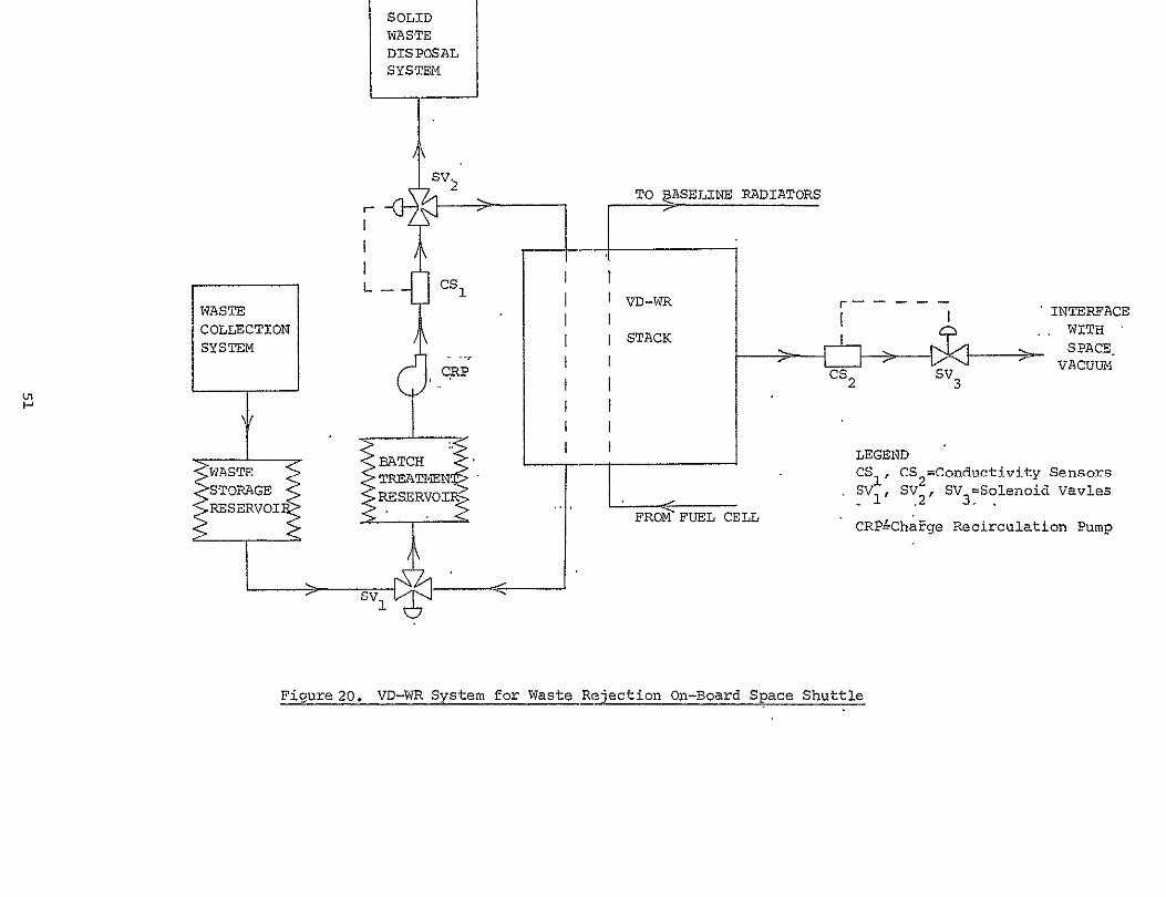