SUMMA D TERM EFEREN CE FOR PHYSICAL T MARK ET DEVELOPMENT FOR

The Handy Board Technical Reference
Fred G. Martin!
The Handy Board is a hand-held, battery-powered microcontroller board ideal for personal and educationalrobotics projects. Based on the Motorola 68HC11 microprocessor, the Handy Board includes 32K of battery-backed static RAM, outputs for four DC motors, inputs for a variety of sensors, and a 16!2 character LCD screen.The Handy Board runs Interactive C, a cross-platform, multi-tasking version of the C programming language.
The Handy Board is distributed under MIT’s free licensing policy, in which the design may be licensed for forpersonal, educational, or commercial use with no charge.
!University of Massachusetts Lowell, Computer Science Department, 1 University Avenue, Lowell, MA 01854. E-mail:[email protected]. This document is Copyright c" 1991–2007 by Fred G. Martin. It may be distributed freely in verbatim formprovided that no fee is collected for its distribution (other than reasonable reproduction and mailing costs) and this copyright noticeis included. An electronic version of this document and the freely distributable software described herein are available from the HandyBoard home page at http://handyboard.com/.
1


Contents
1 Specifications 1
2 Quick Start 2
3 Ports and Connectors 3
4 Interactive C 54.1 Using IC . . . . . . . . . . . . . . . . . . . . . . . . . . . . . . . . . . . . . . . . . . . . . . . . . . . 5
4.1.1 IC Commands . . . . . . . . . . . . . . . . . . . . . . . . . . . . . . . . . . . . . . . . . . . 64.1.2 Line Editing . . . . . . . . . . . . . . . . . . . . . . . . . . . . . . . . . . . . . . . . . . . . 64.1.3 The Main Function . . . . . . . . . . . . . . . . . . . . . . . . . . . . . . . . . . . . . . . . . 6
4.2 A Quick C Tutorial . . . . . . . . . . . . . . . . . . . . . . . . . . . . . . . . . . . . . . . . . . . . . 64.3 Data Types, Operations, and Expressions . . . . . . . . . . . . . . . . . . . . . . . . . . . . . . . . 8
4.3.1 Variable Names . . . . . . . . . . . . . . . . . . . . . . . . . . . . . . . . . . . . . . . . . . . 84.3.2 Data Types . . . . . . . . . . . . . . . . . . . . . . . . . . . . . . . . . . . . . . . . . . . . . 84.3.3 Local and Global Variables . . . . . . . . . . . . . . . . . . . . . . . . . . . . . . . . . . . . 84.3.4 Constants . . . . . . . . . . . . . . . . . . . . . . . . . . . . . . . . . . . . . . . . . . . . . . 94.3.5 Operators . . . . . . . . . . . . . . . . . . . . . . . . . . . . . . . . . . . . . . . . . . . . . . 94.3.6 Assignment Operators and Expressions . . . . . . . . . . . . . . . . . . . . . . . . . . . . . 104.3.7 Increment and Decrement Operators . . . . . . . . . . . . . . . . . . . . . . . . . . . . . . . 104.3.8 Precedence and Order of Evaluation . . . . . . . . . . . . . . . . . . . . . . . . . . . . . . . 11
4.4 Control Flow . . . . . . . . . . . . . . . . . . . . . . . . . . . . . . . . . . . . . . . . . . . . . . . . 114.4.1 Statements and Blocks . . . . . . . . . . . . . . . . . . . . . . . . . . . . . . . . . . . . . . . 114.4.2 If-Else . . . . . . . . . . . . . . . . . . . . . . . . . . . . . . . . . . . . . . . . . . . . . . . . 114.4.3 While . . . . . . . . . . . . . . . . . . . . . . . . . . . . . . . . . . . . . . . . . . . . . . . . 114.4.4 For . . . . . . . . . . . . . . . . . . . . . . . . . . . . . . . . . . . . . . . . . . . . . . . . . . 124.4.5 Break . . . . . . . . . . . . . . . . . . . . . . . . . . . . . . . . . . . . . . . . . . . . . . . . 12
4.5 LCD Screen Printing . . . . . . . . . . . . . . . . . . . . . . . . . . . . . . . . . . . . . . . . . . . . 124.5.1 Printing Examples . . . . . . . . . . . . . . . . . . . . . . . . . . . . . . . . . . . . . . . . . 124.5.2 Formatting Command Summary . . . . . . . . . . . . . . . . . . . . . . . . . . . . . . . . . 134.5.3 Special Notes . . . . . . . . . . . . . . . . . . . . . . . . . . . . . . . . . . . . . . . . . . . . 13
4.6 Arrays and Pointers . . . . . . . . . . . . . . . . . . . . . . . . . . . . . . . . . . . . . . . . . . . . 134.6.1 Declaring and Initializing Arrays . . . . . . . . . . . . . . . . . . . . . . . . . . . . . . . . . 134.6.2 Passing Arrays as Arguments . . . . . . . . . . . . . . . . . . . . . . . . . . . . . . . . . . . 144.6.3 Declaring Pointer Variables . . . . . . . . . . . . . . . . . . . . . . . . . . . . . . . . . . . . 144.6.4 Passing Pointers as Arguments . . . . . . . . . . . . . . . . . . . . . . . . . . . . . . . . . . 14
4.7 Library Functions . . . . . . . . . . . . . . . . . . . . . . . . . . . . . . . . . . . . . . . . . . . . . . 154.7.1 Output Control . . . . . . . . . . . . . . . . . . . . . . . . . . . . . . . . . . . . . . . . . . . 154.7.2 Sensor Input . . . . . . . . . . . . . . . . . . . . . . . . . . . . . . . . . . . . . . . . . . . . 164.7.3 Time Commands . . . . . . . . . . . . . . . . . . . . . . . . . . . . . . . . . . . . . . . . . . 174.7.4 Tone Functions . . . . . . . . . . . . . . . . . . . . . . . . . . . . . . . . . . . . . . . . . . . 18
4.8 Multi-Tasking . . . . . . . . . . . . . . . . . . . . . . . . . . . . . . . . . . . . . . . . . . . . . . . . 184.8.1 Overview . . . . . . . . . . . . . . . . . . . . . . . . . . . . . . . . . . . . . . . . . . . . . . 184.8.2 Creating New Processes . . . . . . . . . . . . . . . . . . . . . . . . . . . . . . . . . . . . . . 194.8.3 Destroying Processes . . . . . . . . . . . . . . . . . . . . . . . . . . . . . . . . . . . . . . . . 194.8.4 Process Management Commands . . . . . . . . . . . . . . . . . . . . . . . . . . . . . . . . . 204.8.5 Process Management Library Functions . . . . . . . . . . . . . . . . . . . . . . . . . . . . . 20
4.9 Floating Point Functions . . . . . . . . . . . . . . . . . . . . . . . . . . . . . . . . . . . . . . . . . . 204.10 Memory Access Functions . . . . . . . . . . . . . . . . . . . . . . . . . . . . . . . . . . . . . . . . . 214.11 Error Handling . . . . . . . . . . . . . . . . . . . . . . . . . . . . . . . . . . . . . . . . . . . . . . . 21
4.11.1 Compile-Time Errors . . . . . . . . . . . . . . . . . . . . . . . . . . . . . . . . . . . . . . . . 224.11.2 Run-Time Errors . . . . . . . . . . . . . . . . . . . . . . . . . . . . . . . . . . . . . . . . . . 22
i
5 Sensors and Motors 225.1 Connector Wiring Technique . . . . . . . . . . . . . . . . . . . . . . . . . . . . . . . . . . . . . . . 22
5.1.1 Wire Type . . . . . . . . . . . . . . . . . . . . . . . . . . . . . . . . . . . . . . . . . . . . . 235.1.2 Stripping and Tinning Wire Ends . . . . . . . . . . . . . . . . . . . . . . . . . . . . . . . . . 235.1.3 Installing Heat Shrink Tubing . . . . . . . . . . . . . . . . . . . . . . . . . . . . . . . . . . . 235.1.4 Soldering to Male Header . . . . . . . . . . . . . . . . . . . . . . . . . . . . . . . . . . . . . 245.1.5 Shrinking the Tubing . . . . . . . . . . . . . . . . . . . . . . . . . . . . . . . . . . . . . . . 25
5.2 Motors . . . . . . . . . . . . . . . . . . . . . . . . . . . . . . . . . . . . . . . . . . . . . . . . . . . . 255.3 Sensors . . . . . . . . . . . . . . . . . . . . . . . . . . . . . . . . . . . . . . . . . . . . . . . . . . . 26
5.3.1 Basic Sensor Connector . . . . . . . . . . . . . . . . . . . . . . . . . . . . . . . . . . . . . . 265.3.2 Switch Sensor . . . . . . . . . . . . . . . . . . . . . . . . . . . . . . . . . . . . . . . . . . . . 275.3.3 Photocell Sensor . . . . . . . . . . . . . . . . . . . . . . . . . . . . . . . . . . . . . . . . . . 275.3.4 Infrared Reflectance Sensor . . . . . . . . . . . . . . . . . . . . . . . . . . . . . . . . . . . . 28
6 Battery Maintenance 306.1 Battery Charging . . . . . . . . . . . . . . . . . . . . . . . . . . . . . . . . . . . . . . . . . . . . . . 306.2 Adapter Specifications . . . . . . . . . . . . . . . . . . . . . . . . . . . . . . . . . . . . . . . . . . . 30
7 Part Listing 31
8 Schematic Drawings 328.1 CPU and Memory . . . . . . . . . . . . . . . . . . . . . . . . . . . . . . . . . . . . . . . . . . . . . 328.2 Motor Outputs . . . . . . . . . . . . . . . . . . . . . . . . . . . . . . . . . . . . . . . . . . . . . . . 338.3 Digital Inputs . . . . . . . . . . . . . . . . . . . . . . . . . . . . . . . . . . . . . . . . . . . . . . . . 348.4 Analog Inputs . . . . . . . . . . . . . . . . . . . . . . . . . . . . . . . . . . . . . . . . . . . . . . . . 348.5 Infrared Transmission . . . . . . . . . . . . . . . . . . . . . . . . . . . . . . . . . . . . . . . . . . . 358.6 Power Supply . . . . . . . . . . . . . . . . . . . . . . . . . . . . . . . . . . . . . . . . . . . . . . . . 358.7 Infrared Reception . . . . . . . . . . . . . . . . . . . . . . . . . . . . . . . . . . . . . . . . . . . . . 368.8 Serial Interface and Battery Charger . . . . . . . . . . . . . . . . . . . . . . . . . . . . . . . . . . . 36
9 Printed Circuit Board Layouts 379.1 Handy Board Component Side . . . . . . . . . . . . . . . . . . . . . . . . . . . . . . . . . . . . . . 379.2 Handy Board Solder Side . . . . . . . . . . . . . . . . . . . . . . . . . . . . . . . . . . . . . . . . . 389.3 Handy Board Silkscreen . . . . . . . . . . . . . . . . . . . . . . . . . . . . . . . . . . . . . . . . . . 399.4 Interface/Charger Board Component Side . . . . . . . . . . . . . . . . . . . . . . . . . . . . . . . . 409.5 Interface/Charger Board Solder Side . . . . . . . . . . . . . . . . . . . . . . . . . . . . . . . . . . . 409.6 Interface/Charger Board Silkscreen . . . . . . . . . . . . . . . . . . . . . . . . . . . . . . . . . . . . 41
10 Pin-Out Detail 42
11 Vendors 43
12 Handy Board Community 43
13 Licensing 43
ii

1 Specifications
The Handy Board features:
• 52–pin Motorola 68HC11 microprocessor with system clock at 2 MHz.
• 32K of battery-backed CMOS static RAM.
• Two TI SN754410NE chips capable of driving four DC motors at 1 amp per motor.
• 16 ! 2 character LCD screen.
• Two user-programmable buttons, one knob, and piezo beeper.
• Powered header inputs for 7 analog sensors and 9 digital sensors.
• Internal 9.6v nicad battery with built-in recharging circuit.
• Hardware 38 kHz oscillator and drive transistor for IR output and on-board 38 kHz IR receiver.
• 8-pin powered connector to the 68HC11 SPI circuit (1 Mbaud serial peripheral interface).
• Expansion bus with chip selects allows easy expansion using inexpensive digital I/O latches.
• Board size of 4.25 ! 3.15 inches, designed for a commercial, high grade plastic enclosure which holds batterypack beneath the board.
1

2 Quick Start
Interactive C (or, IC) is the most popular compiler software used with the Handy Board. It is maintained bythe Kiss Institute for Practical Robotics (KIPR).
Interactive C may be downloaded from www.kipr.org/ic. IC is provided free of charge as a service to educatorsand the general public by KIPR.
Here are the steps to getting started with the Handy Board and Interactive C:
1. Attach the Handy Board’s separate Serial Interface board to your host computer:
• There are two variants of the interface board: Serial and USB.
– If using Serial Interface. Connect the Serial Interface board to the host computer using astandard 9-pin to 25-pin modem cable.
– If using Serial Interface with USB-serial adapter. Use a USB-Serial adapter cable if yourcomputer does not have a serial port. Install the drivers for the adapter cable if necessary.
– If using USB Interface. Install “virtual COM port” drivers from http://ftdichip.com/Drivers/VCP.htm.
• Using a wall adapter, attach power to the Serial Interface board. The board’s Red PWR LED shouldlight up.
• Connect the Handy Board to the Serial Interface using a standard 4–wire telephone cable.
2. Initialize the board by downloading the pcode/firmware for Interactive C. Here are the steps:
• Launch Interactive C version 4.x or higher.• Select Handy Board from the Controller Type dialog.
• Choose Connect Later from the Communications Dialog.
• Choose Download Firmware from the Tools menu. Select the proper serial port, click DownloadFirmware, and follow the on-screen instructions.In this step, you will put the Handy Board into a special bootstrap download mode, by holding downthe Stop button while turning on system power. The pair of LED’s by the two push buttons shouldlight up, and then turn o!. When power is on and both of the LED’s are o!, the Handy Board is indownload mode.
3. After the firmware is downloaded, the Handy Board should beep, and the Interactive C welcome messageshould appear on the Handy Board’s LCD screen.
4. You are ready to use Interactive C.
2
3 Ports and Connectors
(17) LCD screen(1) powerswitch
OFF
ON(2) computer
connector
(3) 4 DCmotor outputs
andindicators
(4) “Start”button (5) “Stop”
button(6) low battery
indicator(7) power/ready
indicator
(8)9 digitalinputs
(9)7 analog
inputs(10)
IR outputand
indicator
(11)IR inputsensor
(13) userknob
(14) batterytrickle-charge
connector
(15) chargeindicator
(12) analogexpansion
header
(19) powerexpansion
header
(16) SPIexpansion
header
(18) piezobeeper
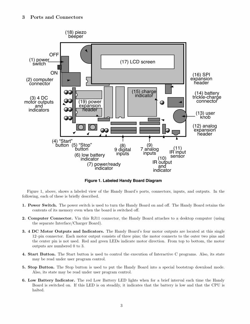
Figure 1. Labeled Handy Board Diagram
Figure 1, above, shows a labeled view of the Handy Board’s ports, connectors, inputs, and outputs. In thefollowing, each of these is briefly described.
1. Power Switch. The power switch is used to turn the Handy Board on and o!. The Handy Board retains thecontents of its memory even when the board is switched o!.
2. Computer Connector. Via this RJ11 connector, the Handy Board attaches to a desktop computer (usingthe separate Interface/Charger Board).
3. 4 DC Motor Outputs and Indicators. The Handy Board’s four motor outputs are located at this single12–pin connector. Each motor output consists of three pins; the motor connects to the outer two pins andthe center pin is not used. Red and green LEDs indicate motor direction. From top to bottom, the motoroutputs are numbered 0 to 3.
4. Start Button. The Start button is used to control the execution of Interactive C programs. Also, its statemay be read under user program control.
5. Stop Button. The Stop button is used to put the Handy Board into a special bootstrap download mode.Also, its state may be read under user program control.
6. Low Battery Indicator. The red Low Battery LED lights when for a brief interval each time the HandyBoard is switched on. If this LED is on steadily, it indicates that the battery is low and that the CPU ishalted.
3

7. Power/Ready Indicator. The green Power/Ready LED lights when the Handy Board is in normal operation,and flashes when the Handy Board is transmitting serial data. If the board is powered on and this LED iso!, then the Handy Board is in special bootstrap mode.
8. 9 Digital Inputs. The bank of digital input ports is here. From right to left, the digital inputs are numbered7 to 15.
9. 7 Analog Inputs. The bank of analog input ports is here. From right to left, the analog inputs are numbered0 to 6.
10. IR Output and Indicator. The infrared output port is here. The red indicator LED lights when the outputis enabled.
11. IR Input Sensor. The dark green-colored infrared sensor is here.
12. Analog Expansion Header. The analog expansion header is a 1!4 connector row located above analoginputs 0 to 3.
13. User Knob. The user knob is a trimmer potentiometer whose value can be read under user program control.
14. Battery Trickle-Charge Connector. The battery charge connector is a coaxial power jack to accept a 12volt signal for trickle-charging the Handy Board’s internal battery.
15. Charge Indicator. The yellow charge indicator LED lights when the Handy Board is charging via the coaxialpower jack.
16. SPI Expansion Header. The SPI expansion header is a 2!4 pin jack that allows connection with the 6811’sserial peripheral interface circuit. See the CPU and memory schematic diagram for a pin-out of this connector.
17. LCD Screen. The Handy Board is provided with a 16!2 LCD screen which can display data under usercontrol.
18. Piezo Beeper. The Handy Board has a simple piezo beeper for generating tones under user control.
19. Power Expansion Header. The power expansion header is a 1!4 pin jack that provides access to theunregulated motor power and ground signals.
4

4 Interactive C
Interactive C (IC for short) is a C language consisting of a compiler (with interactive command-line compilationand debugging) and a run-time machine language module. IC implements a subset of C including control structures(for, while, if, else), local and global variables, arrays, pointers, 16-bit and 32-bit integers, and 32-bit floatingpoint numbers.
IC works by compiling into pseudo-code for a custom stack machine, rather than compiling directly into nativecode for a particular processor. This pseudo-code (or p-code) is then interpreted by the run-time machine languageprogram. This unusual approach to compiler design allows IC to o!er the following design tradeo!s:
• Interpreted execution that allows run-time error checking and prevents crashing. For example, IC doesarray bounds checking at run-time to protect against programming errors.
• Ease of design. Writing a compiler for a stack machine is significantly easier than writing one for a typicalprocessor. Since IC’s p-code is machine-independent, porting IC to another processor entails rewriting thep-code interpreter, rather than changing the compiler.
• Small object code. Stack machine code tends to be smaller than a native code representation.
• Multi-tasking. Because the pseudo-code is fully stack-based, a process’s state is defined solely by its stackand its program counter. It is thus easy to task-switch simply by loading a new stack pointer and programcounter. This task-switching is handled by the run-time module, not by the compiler.
Since IC’s ultimate performance is limited by the fact that its output p-code is interpreted, these advantagesare taken at the expense of raw execution speed. Still, IC is no slouch.
IC was designed and implemented by Randy Sargent with the assistance of Fred Martin. This manualincludes reference material for both the original command-line version of IC (e.g., the open-source v2.8xdistribution) and the more modern GUI version (v4.x and above, maintained by the Kiss Institute forPractical Robotics).
4.1 Using IC
Before IC can be used, the Handy Board must have the runtime “firmware” or “pcode” operating programalready loaded.
When IC is booted, it immediately attempts to connect with the Handy Board, which should be turned on andrunning the pcode hb.s19 program. In later version of IC, the firmware is named lib hb exp.frm.
After synchronizing with the Handy Board, IC compiles and downloads the default set of library files, and thenpresents the user with the “C>” prompt. At this prompt, either an IC command or C–language expression may beentered.
All C expressions must be ended with a semicolon. For example, to evaluate the arithmetic expression 1 + 2,type the following:
C> 1 + 2;
(The underlined portion indicates user input.) When this expression is typed, it is compiled by IC and thendownloaded to the Handy Board for evaluation. The Handy Board then evaluates the compiled form and returnsthe result, which is printed on the IC console.
To evaluate a series of expressions, create a C block by beginning with an open curly brace “{” and ending witha close curly brace “}”. The following example creates a local variable i and prints the sum i+7 to the HandyBoard’s LCD screen:
C> {int i=3; printf("%d", i+7);}
5

Keystroke Functionctrl-A beginning-of-linectrl-B backward-char" backward-charctrl-D delete-charctrl-E end-of-linectrl-F forward-char# forward-charctrl-K kill-line
Figure 2. IC Command-Line Keystroke Mappings
4.1.1 IC Commands
IC responds to the following commands. These commands are available as menu selections from the IC application.
• Load file. The command load <filename> compiles and loads the named file. The Handy Board must beattached for this to work. IC looks first in the local directory and then in the IC library path for files.
Several files may be loaded into IC at once, allowing programs to be defined in multiple files.
• Unload file. The command unload < filename > unloads the named file, and re-downloads remaining files.
• List files, functions, or globals. The command list files displays the names of all files presently loadedinto IC. The command list functions displays the names of presently defined C functions. The commandlist globals displays the names of all currently defined global variables.
• Kill all processes. The command kill all kills all currently running processes.
• Print process status. The command ps prints the status of currently running processes.
• Help. The command help displays a help screen of IC commands.
• Quit. The command quit exits IC. In the MS-DOS version, ctrl-C can also be used.
4.1.2 Line Editing
IC has a built-in line editor and command history, allowing editing and re-use of previously typed statements andcommands. The mnemonics for these functions are based on standard Emacs control key assignments.
To scan forward and backward in the command history, type ctrl-P or $ for backward, and ctrl-N or %for forward.
Figure 2 shows the keystroke mappings understood by IC.IC does parenthesis-balance-highlighting as expressions are typed.
4.1.3 The Main Function
After functions have been downloaded to the Handy Board, they can be invoked from the IC prompt. If one ofthe functions is named main(), it will automatically be run when the Handy Board is reset.
To reset the Handy Board without running the main() function (for instance, when hooking the board back tothe computer), hold down the Start button when turning on the Handy Board. The board will reset withoutrunning main().
4.2 A Quick C Tutorial
Most C programs consist of function definitions and data structures. Here is a simple C program that defines asingle function, called main.
6

void main(){
printf("Hello, world!\n");}
All functions must have a return value; that is, the value that they return when they finish execution. main hasa return value type of void, which is the “null” type. Other types include integers (int) and floating point numbers(float). This function declaration information must precede each function definition.
Immediately following the function declaration is the function’s name (in this case, main). Next, in parentheses,are any arguments (or inputs) to the function. main has none, but a empty set of parentheses is still required.
After the function arguments is an open curly-brace “{”. This signifies the start of the actual function code.Curly-braces signify program blocks, or chunks of code.
Next comes a series of C statements. Statements demand that some action be taken. Our demonstrationprogram has a single statement, a printf (formatted print). This will print the message “Hello, world!” to theLCD display. The \n indicates end-of-line.
The printf statement ends with a semicolon (“;”). All C statements must be ended by a semicolon. BeginningC programmers commonly make the error of omitting the semicolon that is required at the end of each statement.
The main function is ended by the close curly-brace “}”.
Let’s look at an another example to learn some more features of C. The following code defines the functionsquare, which returns the mathematical square of a number.
int square(int n){
return n * n;}
The function is declared as type int, which means that it will return an integer value. Next comes the functionname square, followed by its argument list in parenthesis. square has one argument, n, which is an integer. Noticehow declaring the type of the argument is done similarly to declaring the type of the function.
When a function has arguments declared, those argument variables are valid within the “scope” of the function(i.e., they only have meaning within the function’s own code). Other functions may use the same variable namesindependently.
The code for square is contained within the set of curly braces. In fact, it consists of a single statement: thereturn statement. The return statement exits the function and returns the value of the C expression that followsit (in this case “n * n”).
Expressions are evaluated according set of precendence rules depending on the various operations within theexpression. In this case, there is only one operation (multiplication), signified by the “*”, so precedence is not anissue.
Let’s look at an example of a function that performs a function call to the square program.
float hypotenuse(int a, int b){
float h;
h = sqrt((float)(square(a) + square(b)));
return h;}
This code demonstrates several more features of C. First, notice that the floating point variable h is defined atthe beginning of the hypotenuse function. In general, whenever a new program block (indicated by a set of curlybraces) is begun, new local variables may be defined.
The value of h is set to the result of a call to the sqrt function. It turns out that sqrt is a built-in function thattakes a floating point number as its argument.
We want to use the square function we defined earlier, which returns its result as an integer. But the sqrt
function requires a floating point argument. We get around this type incompatibility by coercing the integer sum(square(a) + square(b)) into a float by preceding it with the desired type, in parentheses. Thus, the integer sumis made into a floating point number and passed along to sqrt.
The hypotenuse function finishes by returning the value of h.
This concludes the brief C tutorial.
7

4.3 Data Types, Operations, and Expressions
Variables and constants are the basic data objects in a C program. Declarations list the variables to be used,state what type they are, and may set their initial value. Operators specify what is to be done to them. Expressionscombine variables and constants to create new values.
4.3.1 Variable Names
Variable names are case-sensitive. The underscore character is allowed and is often used to enhance the readabilityof long variable names. C keywords like if, while, etc. may not be used as variable names.
Global variables and functions may not have the same name. In addition, local variables named the same asfunctions prevent the use of that function within the scope of the local variable.
4.3.2 Data Types
IC supports the following data types:
16-bit Integers 16-bit integers are signified by the type indicator int. They are signed integers, and may bevalued from &32,768 to +32,767 decimal.
32-bit Integers 32-bit integers are signified by the type indicator long. They are signed integers, and may bevalued from &2,147,483,648 to +2,147,483,647 decimal.
32-bit Floating Point Numbers Floating point numbers are signified by the type indicator float. They haveapproximately seven decimal digits of precision and are valued from about 10!38 to 1038.
8-bit Characters Characters are an 8-bit number signified by the type indicator char. A character’s valuetypically represents a printable symbol using the standard ASCII character code.
Arrays of characters (character strings) are supported, but individual characters are not.
4.3.3 Local and Global Variables
If a variable is declared within a function, or as an argument to a function, its binding is local, meaning that thevariable has existence only that function definition.
If a variable is declared outside of a function, it is a global variable. It is defined for all functions, includingfunctions that are defined in files other than the one in which the global variable was declared.
Variable Initialization Local and global variables can be initialized when they are declared. If no initializationvalue is given, the variable is initialized to zero.
int foo(){int x; /* create local variable x
with initial value 0 */int y= 7; /* create local variable y
with initial value 7 */...
}
float z=3.0; /* create global variable zwith initial value 3.0 */
Local variables are initialized whenever the function containing them runs.Global variables are initialized whenever a reset condition occurs. Reset conditions occur when:
1. New code is downloaded;
2. The main() procedure is run;
3. System hardware reset occurs.
8

Persistent Global Variables A special uninitialized form of global variable, called the “persistent” type, hasbeen implemented for IC. A persistent global is not initialized upon the conditions listed for normal global variables.
To make a persistent global variable, prefix the type specifier with the key word persistent. For example, thestatement
persistent int i;
creates a global integer called i. The initial value for a persistent variable is arbitrary; it depends on the contentsof RAM that were assigned to it. Initial values for persistent variables cannot be specified in their declarationstatement.
Persistent variables keep their state when the Handy Board is turned o! and on, when main is run, and whensystem reset occurs. Persistent variables, in general, will lose their state when a new program is downloaded.However, it is possible to prevent this from occurring. If persistent variables are declared at the beginning of thecode, before any function or non-persistent globals, they will be re-assigned to the same location in memory whenthe code is re-compiled, and thus their values will be preserved over multiple downloads.
If the program is divided into multiple files and it is desired to preserve the values of persistent variables, thenall of the persistent variables should be declared in one particular file and that file should be placed first in theload ordering of the files.
Persistent variables were created with two applications in mind:
• Calibration and configuration values that do not need to be re-calculated on every reset condition.
• Robot learning algorithms that might occur over a period when the robot is turned on and o!.
4.3.4 Constants
Integers Integers may be defined in decimal integer format (e.g., 4053 or -1), hexadecimal format using the “0x”prefix (e.g., 0x1fff), and a non-standard but useful binary format using the “0b” prefix (e.g., 0b1001001). Octalconstants using the zero prefix are not supported.
Long Integers Long integer constants are created by appending the su"x “l” or “L” (upper- or lower-casealphabetic L) to a decimal integer. For example, 0L is the long zero. Either the upper or lower-case “L” may beused, but upper-case is the convention for readability.
Floating Point Numbers Floating point numbers may use exponential notation (e.g., “10e3” or “10E3”) ormust contain the decimal period. For example, the floating point zero can be given as “0.”, “0.0”, or “0E1”, butnot as just “0”.
Characters and Character Strings Quoted characters return their ASCII value (e.g., ’x’).Character strings are defined with quotation marks, e.g., "This is a character string.".
4.3.5 Operators
Each of the data types has its own set of operators that determine which operations may be performed on them.
Integers The following operations are supported on integers:
• Arithmetic. addition +, subtraction -, multiplication *, division /.
• Comparison. greater-than >, less-than <, equality ==, greater-than-equal >=, less-than-equal <=.
• Bitwise Arithmetic. bitwise-OR |, bitwise-AND &, bitwise-exclusive-OR ^, bitwise-NOT ~.
• Boolean Arithmetic. logical-OR ||, logical-AND &&, logical-NOT !.When a C statement uses a boolean value (for example, if), it takes the integer zero as meaning false, andany integer other than zero as meaning true. The boolean operators return zero for false and one for true.Boolean operators && and || stop executing as soon as the truth of the final expression is determined. Forexample, in the expression a && b, if a is false, then b does not need to be evaluated because the result mustbe false. The && operator “knows this” and does not evaluate b.
9

Long Integers A subset of the operations implemented for integers are implemented for long integers: arithmeticaddition +, subtraction -, and multiplication *, and the integer comparison operations. Bitwise and booleanoperations and division are not supported.
Floating Point Numbers IC uses a package of public-domain floating point routines distributed by Motorola.This package includes arithmetic, trigonometric, and logarithmic functions.
The following operations are supported on floating point numbers:
• Arithmetic. addition +, subtraction -, multiplication *, division /.
• Comparison. greater-than >, less-than <, equality ==, greater-than-equal >=, less-than-equal <=.
• Built-in Math Functions. A set of trigonometric, logarithmic, and exponential functions is supported, asdiscussed in Section 4.9 of this document.
Characters Characters are only allowed in character arrays. When a cell of the array is referenced, it is auto-matically coerced into a integer representation for manipulation by the integer operations. When a value is storedinto a character array, it is coerced from a standard 16-bit integer into an 8-bit character (by truncating the uppereight bits).
4.3.6 Assignment Operators and Expressions
The basic assignment operator is =. The following statement adds 2 to the value of a.
a = a + 2;
The abbreviated form
a += 2;
could also be used to perform the same operation.
All of the following binary operators can be used in this fashion:
+ - * / % << >> & ^ |
4.3.7 Increment and Decrement Operators
The increment operator “++” increments the named variable. For example, the statement “a++” is equivalent to“a= a+1” or “a+= 1”.
A statement that uses an increment operator has a value. For example, the statement
a= 3;printf("a=%d a+1=%d\n", a, ++a);
will display the text “a=3 a+1=4.”If the increment operator comes after the named variable, then the value of the statement is calculated after
the increment occurs. So the statement
a= 3;printf("a=%d a+1=%d\n", a, a++);
would display “a=3 a+1=3” but would finish with a set to 4.
The decrement operator “--” is used in the same fashion as the increment operator.
10

4.3.8 Precedence and Order of Evaluation
The following table summarizes the rules for precedence and associativity for the C operators. Operators listedearlier in the table have higher precedence; operators on the same line of the table have equal precedence.
Operator Associativity() [] left to right! ~ ++ -- - ( type ) right to left* / % left to right+ - left to right<< >> left to right< <= > >= left to right== != left to right& left to right^ left to right| left to right&& left to right|| right to left= += -= etc. right to left, left to right
4.4 Control Flow
IC supports most of the standard C control structures. One notable exception is the case and switch statement,which is not supported.
4.4.1 Statements and Blocks
A single C statement is ended by a semicolon. A series of statements may be grouped together into a block usingcurly braces. Inside a block, local variables may be defined.
There is never a semicolon after a right brace that ends a block.
4.4.2 If-Else
The if else statement is used to make decisions. The syntax is:
if ( expression )statement-1
elsestatement-2
expression is evaluated; if it is not equal to zero (e.g., logic true), then statement-1 is executed.The else clause is optional. If the if part of the statement did not execute, and the else is present, then
statement-2 executes.
4.4.3 While
The syntax of a while loop is the following:
while ( expression )statement
while begins by evaluating expression. If it is false, then statement is skipped. If it is true, then statementis evaluated. Then the expression is evaluated again, and the same check is performed. The loop exits whenexpression becomes zero.
One can easily create an infinite loop in C using the while statement:
while (1)statement
11

4.4.4 For
The syntax of a for loop is the following:
for ( expr-1 ; expr-2 ; expr-3 )statement
This is equivalent to the following construct using while:
expr-1 ;while ( expr-2 ) {
statementexpr-3 ;
}
Typically, expr-1 is an assignment, expr-2 is a relational expression, and expr-3 is an increment or decrement ofsome manner. For example, the following code counts from 0 to 99, printing each number along the way:
int i;for (i= 0; i < 100; i++)printf("%d\n", i);
4.4.5 Break
Use of the break provides an early exit from a while or a for loop.
4.5 LCD Screen Printing
IC has a version of the C function printf for formatted printing to the LCD screen.
The syntax of printf is the following:
printf( format-string , [ arg-1 ] , . . . , [ arg-N ] )
This is best illustrated by some examples.
4.5.1 Printing Examples
Example 1: Printing a message. The following statement prints a text string to the screen.
printf("Hello, world!\n");
In this example, the format string is simply printed to the screen.The character “\n” at the end of the string signifies end-of-line. When an end-of-line character is printed, the
LCD screen will be cleared when a subsequent character is printed. Thus, most printf statements are terminatedby a \n.
Example 2: Printing a number. The following statement prints the value of the integer variable x with a briefmessage.
printf("Value is %d\n", x);
The special form %d is used to format the printing of an integer in decimal format.
Example 3: Printing a number in binary. The following statement prints the value of the integer variable x
as a binary number.
printf("Value is %b\n", x);
The special form %b is used to format the printing of an integer in binary format. Only the low byte of the numberis printed.
12
Example 4: Printing a floating point number. The following statement prints the value of the floating pointvariable n as a floating point number.
printf("Value is %f\n", n);
The special form %f is used to format the printing of floating point number.
Example 5: Printing two numbers in hexadecimal format.printf("A=%x B=%x\n", a, b);
The form %x formats an integer to print in hexadecimal.
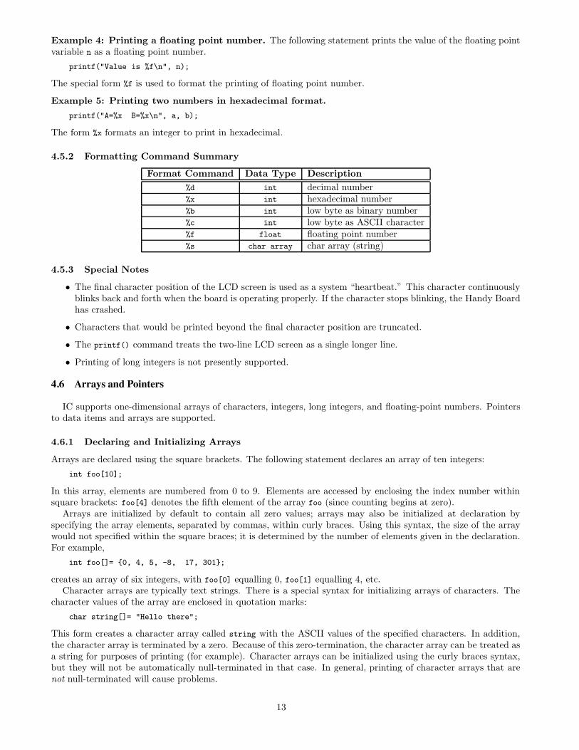
4.5.2 Formatting Command Summary
Format Command Data Type Description%d int decimal number%x int hexadecimal number%b int low byte as binary number%c int low byte as ASCII character%f float floating point number%s char array char array (string)
4.5.3 Special Notes
• The final character position of the LCD screen is used as a system “heartbeat.” This character continuouslyblinks back and forth when the board is operating properly. If the character stops blinking, the Handy Boardhas crashed.
• Characters that would be printed beyond the final character position are truncated.
• The printf() command treats the two-line LCD screen as a single longer line.
• Printing of long integers is not presently supported.
4.6 Arrays and Pointers
IC supports one-dimensional arrays of characters, integers, long integers, and floating-point numbers. Pointersto data items and arrays are supported.
4.6.1 Declaring and Initializing Arrays
Arrays are declared using the square brackets. The following statement declares an array of ten integers:int foo[10];
In this array, elements are numbered from 0 to 9. Elements are accessed by enclosing the index number withinsquare brackets: foo[4] denotes the fifth element of the array foo (since counting begins at zero).
Arrays are initialized by default to contain all zero values; arrays may also be initialized at declaration byspecifying the array elements, separated by commas, within curly braces. Using this syntax, the size of the arraywould not specified within the square braces; it is determined by the number of elements given in the declaration.For example,
int foo[]= {0, 4, 5, -8, 17, 301};
creates an array of six integers, with foo[0] equalling 0, foo[1] equalling 4, etc.Character arrays are typically text strings. There is a special syntax for initializing arrays of characters. The
character values of the array are enclosed in quotation marks:char string[]= "Hello there";
This form creates a character array called string with the ASCII values of the specified characters. In addition,the character array is terminated by a zero. Because of this zero-termination, the character array can be treated asa string for purposes of printing (for example). Character arrays can be initialized using the curly braces syntax,but they will not be automatically null-terminated in that case. In general, printing of character arrays that arenot null-terminated will cause problems.
13

4.6.2 Passing Arrays as Arguments
When an array is passed to a function as an argument, the array’s pointer is actually passed, rather than theelements of the array. If the function modifies the array values, the array will be modified, since there is only onecopy of the array in memory.
In normal C, there are two ways of declaring an array argument: as an array or as a pointer. IC only allowsdeclaring array arguments as arrays.
As an example, the following function takes an index and an array, and returns the array element specified bythe index:
int retrieve_element(int index, int array[]){
return array[index];}
Notice the use of the square brackets to declare the argument array as an array of integers.When passing an array variable to a function, use of the square brackets is not needed:
{int array[10];
retrieve_element(3, array);}
4.6.3 Declaring Pointer Variables
Pointers can be passed to functions which then go on to modify the value of the variable being pointed to. This isuseful because the same function can be called to modify di!erent variables, just by giving it a di!erent pointer.
Pointers are declared with the use of the asterisk (*). In the example
int *foo;float *bar;
foo is declared as a pointer to an integer, and bar is declared as a pointer to a floating point number.To make a pointer variable point at some other variable, the ampersand operator is used. The ampersand
operator returns the address of a variable’s value; that is, the place in memory where the variable’s value is stored.Thus:
int *foo;int x= 5;
foo= &x;
makes the pointer foo “point at” the value of x (which happens to be 5).This pointer can now be used to retrieve the value of x using the asterisk operator. This process is called
de-referencing. The pointer, or reference to a value, is used to fetch the value being pointed at. Thus:
int y;
y= *foo;
sets y equal to the value pointed at by foo. In the previous example, foo was set to point at x, which had the value5. Thus, the result of dereferencing foo yields 5, and y will be set to 5.
4.6.4 Passing Pointers as Arguments
Pointers can be passed to functions; then, functions can change the values of the variables that are pointed at. Thisis termed call-by-reference; the reference, or pointer, to the variable is given to the function that is being called.This is in contrast to call-by-value, the standard way that functions are called, in which the value of a variable isgiven the to function being called.
The following example defines an average sensor function which takes a port number and a pointer to an integervariable. The function will average the sensor and store the result in the variable pointed at by result.
In the code, the function argument is specified as a pointer using the asterisk:
14

void average_sensor(int port, int *result){int sum= 0;int i;
for (i= 0; i< 10; i++) sum += analog(port);
*result= sum/10;}
Notice that the function itself is declared as a void. It does not need to return anything, because it insteadstores its answer in the pointer variable that is passed to it.
The pointer variable is used in the last line of the function. In this statement, the answer sum/10 is stored atthe location pointed at by result. Notice that the asterisk is used to get the location pointed by result.
4.7 Library Functions
Library files provide standard C functions for interfacing with hardware on the Handy Board. These functionsare written either in C or as assembly language drivers. Library files provide functions to do things like controlmotors, make tones, and input sensors values.
IC automatically loads the library file every time it is invoked. The name of the default library file is is containedas a resource within the IC application. On command-line versions of IC, this resource may be modified by invoking“ic -config”. On the Macintosh, the IC application has a STR resource that defines the name of the library file.
The Handy Board’s root library file is named lib hb.lis.
4.7.1 Output Control
DC Motors DC motor ports are numbered from 0 to 3.Motors may be set in a “forward” direction (corresponding to the green motor LED being lit) and a “backward”
direction (corresponding to the motor red LED being lit).The functions fd(int m) and bk(int m) turn motor m on or o!, respectively, at full power. The function off(int
m) turns motor m o!.The power level of motors may also be controlled. This is done in software by a motor on and o! rapidly (a
technique called pulse-width modulation. The motor(int m, int p) function allows control of a motor’s power level.Powers range from 100 (full on in the forward direction) to -100 (full on in the backward direction). The systemsoftware actually only controls motors to seven degrees of power, but argument bounds of &100 and +100 areused.
void fd(int m)Turns motor m on in the forward direction. Example: fd(3);
void bk(int m)Turns motor m on in the backward direction. Example: bk(1);
void off(int m)Turns o! motor m. Example: off(1);
void alloff()
void ao()Turns o! all motors. ao is a short form for alloff.
void motor(int m, int p)Turns on motor m at power level p. Power levels range from 100 for full on forward to -100 for full on backward.
15

Servo Motor A library routine allows control of a single servo motor, using digital input 9, which is actuallythe 6811’s Port A bit 7 (PA7), a bidirectional control pin. Loading the servo library files causes this pin to beemployed as a digital output suitable for driving the control wire of the servo motor.
The servo motor has a three-wire connection: power, ground, and control. These wires are often color-codedred, black, and white, respectively. The control wire is connected to PA7; the ground wire, to board ground; thepower wire, to a +5 volt source. The Handy Board’s regulated +5v supply may be used, though this is not anideal solution because it will tax the regulator. A better solution is a separate battery with a common ground tothe Handy Board or a tap at the +6v position of the Handy Board’s battery back.
The position of the servo motor shaft is controlled by a rectangular waveform that is generated on the PA7 pin.The duration of the positive pulse of the waveform determines the position of the shaft. This pulse repeats every20 milliseconds.
The length of the pulse is set by the library function servo, or by functions calibrated to set the position of theservo by angle.
void servo on()Enables PA7 servo output waveform.
void servo on()Disables PA7 servo output waveform.
int servo(int period)Sets length of servo control pulse. Value is the time in half-microseconds of the positive portion of a rectangular
wave that is generated on the PA7 pin for use in controlling a servo motor. Minimum allowable value is 1400 (i.e.,700 µsec); maximum is 4860.
Function return value is actual period set by driver software.
int servo rad(float angle)Sets servo angle in radians.
int servo deg(float angle)Sets servo angle in degrees.In order to use the servo motor functions, the files servo.icb and servo.c must be loaded.
4.7.2 Sensor Input
int digital(int p)Returns the value of the sensor in sensor port p, as a true/false value (1 for true and 0 for false).Sensors are expected to be active low, meaning that they are valued at zero volts in the active, or true, state.
Thus the library function returns the inverse of the actual reading from the digital hardware: if the reading is zerovolts or logic zero, the digital() function will return true.
If the digital() function is applied to port that is implemented in hardware as an analog input, the result istrue if the analog measurement is less than 127, and false if the reading is greater than or equal to 127.
Ports are numbered as marked on the Handy Board.
int analog(int p)Returns value of sensor port numbered p. Result is integer between 0 and 255.If the analog() function is applied to a port that is implemented digitally in hardware, then the value 0 is
returned if the digital reading is 0, and the value 255 is returned if the digital reading is 1.Ports are numbered as marked on the Handy Board.
User Buttons and Knob The Handy Board has two buttons and a knob whose value can be read by userprograms.
16

int stop button()Returns value of button labelled Stop: 1 if pressed and 0 if released.Example:
/* wait until stop button pressed */while (!stop_button()) {}
int start button()Returns value of button labelled Start.
void stop press()Waits for Stop button to be pressed, then released. Then issues a short beep and returns.The code for stop press is as follows:
while (!stop_button());while (stop_button());beep();
void start press()Like stop press, but for the Start button.
int knob()Returns the position of a knob as a value from 0 to 255.
Infrared Subsystem The Handy Board provides an on-board infrared receiver (the Sharp IS1U60), for infraredinput, and a 40 kHz modulation and power drive circuit, for infrared output. The output circuit requires anexternal infrared LED.
As of this writing, only the infrared receive function is o!cially supported. On the Handy Board web site,contributed software to extend the infrared functionality is available.
To use the infrared reception function, the file sony-ir.icb must be loaded into Interactive C. This file may beadded to the Handy Board default library file, lib hb.lis. Please make sure that the file r22 ir.lis is not presentin the lib hb.lis file.
The sony-ir.icb file adds the capability of receiving infrared codes transmitted by a Sony remote, or a universalremote programmed to transmit Sony infrared codes.
int sony init(1)Enables the infrared driver.
int sony init(0)Disables the infrared driver.
int ir data(int dummy)Returns the data byte last received by the driver, or zero if no data has been received since the last call. A
value must be provided for the dummy argument, but its value is ignored.The infrared sensor is the dark green component in the Handy Board’s lower right hand corner.
4.7.3 Time Commands
System code keeps track of time passage in milliseconds. The time variables are implemented using the long integerdata type. Standard functions allow use floating point variables when using the timing functions.
void reset system time()Resets the count of system time to zero milliseconds.
long mseconds()Returns the count of system time in milliseconds. Time count is reset by hardware reset (i.e., turning the board
o! and on) or the function reset system time(). mseconds() is implemented as a C primitive (not as a libraryfunction).
17

float seconds()Returns the count of system time in seconds, as a floating point number. Resolution is one millisecond.
void sleep(float sec)Waits for an amount of time equal to or slightly greater than sec seconds. sec is a floating point number.Example:
/* wait for 1.5 seconds */sleep(1.5);
void msleep(long msec)Waits for an amount of time equal to or greater than msec milliseconds. msec is a long integer.Example:
/* wait for 1.5 seconds */msleep(1500L);
4.7.4 Tone Functions
Several commands are provided for producing tones on the standard beeper.
void beep()Produces a tone of 500 Hertz for a period of 0.3 seconds.
void tone(float frequency, float length)Produces a tone at pitch frequency Hertz for length seconds. Both frequency and length are floats.
void set beeper pitch(float frequency)Sets the beeper tone to be frequency Hz. The subsequent function is then used to turn the beeper on.
void beeper on()Turns on the beeper at last frequency selected by the former function.
void beeper off()Turns o! the beeper.
4.8 Multi-Tasking
4.8.1 Overview
One of the most powerful features of IC is its multi-tasking facility. Processes can be created and destroyeddynamically during run-time.
Any C function can be spawned as a separate task. Multiple tasks running the same code, but with their ownlocal variables, can be created.
Processes communicate through global variables: one process can set a global to some value, and another processcan read the value of that global.
Each time a process runs, it executes for a certain number of ticks, defined in milliseconds. This value isdetermined for each process at the time it is created. The default number of ticks is five; therefore, a defaultprocess will run for 5 milliseconds until its “turn” ends and the next process is run. All processes are kept track ofin a process table; each time through the table, each process runs once (for an amount of time equal to its numberof ticks).
Each process has its own program stack. The stack is used to pass arguments for function calls, store localvariables, and store return addresses from function calls. The size of this stack is defined at the time a process iscreated. The default size of a process stack is 256 bytes.
Processes that make extensive use of recursion or use large local arrays will probably require a stack size largerthan the default. Each function call requires two stack bytes (for the return address) plus the number of argumentbytes; if the function that is called creates local variables, then they also use up stack space. In addition, Cexpressions create intermediate values that are stored on the stack.
18

It is up to the programmer to determine if a particular process requires a stack size larger than the default. Aprocess may also be created with a stack size smaller than the default, in order to save stack memory space, if itis known that the process will not require the full default amount.
When a process is created, it is assigned a unique process identification number or pid. This number can beused to kill a process.
4.8.2 Creating New Processes
The function to create a new process is start process. start process takes one mandatory argument—the functioncall to be started as a process. There are two optional arguments: the process’s number of ticks and stack size. (Ifonly one optional argument is given, it is assumed to be the ticks number, and the default stack size is used.)
start process has the following syntax:
int start process( function-call( . . . ) , [TICKS] , [STACK-SIZE] )
start process returns an integer, which is the process ID assigned to the new process.The function call may be any valid call of the function used. The following code shows the function main creating
a process:
void check_sensor(int n){while (1)
printf("Sensor %d is %d\n", n, digital(n));}
void main(){start_process(check_sensor(2));
}
Normally when a C functions ends, it exits with a return value or the “void” value. If a function invoked asa process ends, it “dies,” letting its return value (if there was one) disappear. (This is okay, because processescommunicate results by storing them in globals, not by returning them as return values.) Hence in the aboveexample, the check sensor function is defined as an infinite loop, so as to run forever (until the board is reset or akill process is executed).
Creating a process with a non-default number of ticks or a non-default stack size is simply a matter of usingstart process with optional arguments; e.g.
start_process(check_sensor(2), 1, 50);
will create a check sensor process that runs for 1 milliseconds per invocation and has a stack size of 50 bytes (forthe given definition of check sensor, a small stack space would be su"cient).
4.8.3 Destroying Processes
The kill process function is used to destroy processes. Processes are destroyed by passing their process ID numberto kill process, according to the following syntax:
int kill process(int pid)
kill process returns a value indicating if the operation was successful. If the return value is 0, then the processwas destroyed. If the return value is 1, then the process was not found.
The following code shows the main process creating a check sensor process, and then destroying it one secondlater:
void main(){int pid;
pid= start_process(check_sensor(2));sleep(1.0);kill_process(pid);
}
19
4.8.4 Process Management Commands
IC has two commands to help with process management. The commands only work when used at the IC commandline. They are not C functions that can be used in code.
kill allkills all currently running processes.
psprints out a list of the process status.The following information is presented: process ID, status code, program counter, stack pointer, stack pointer
origin, number of ticks, and name of function that is currently executing.
4.8.5 Process Management Library Functions
The following functions are implemented in the standard C library.
void hog processor()Allocates an additional 256 milliseconds of execution to the currently running process. If this function is called
repeatedly, the system will wedge and only execute the process that is calling hog processor(). Only a systemreset will unwedge from this state. Needless to say, this function should be used with extreme care, and shouldnot be placed in a loop, unless wedging the machine is the desired outcome.
void defer()Makes a process swap out immediately after the function is called. Useful if a process knows that it will not need
to do any work until the next time around the scheduler loop. defer() is implemented as a C built-in function.
4.9 Floating Point Functions
In addition to basic floating point arithmetic (addition, subtraction, multiplication, and division) and floatingpoint comparisons, a number of exponential and transcendental functions are built in to IC. These are implementedwith a public domain library of routines provided by Motorola.
Keep in mind that all floating point operations are quite slow; each takes one to several milliseconds to complete.If Interactive C’s speed seems to be poor, extensive use of floating point operations is a likely cause.
float sin(float angle)
Returns sine of angle. Angle is specified in radians; result is in radians.
float cos(float angle)
Returns cosine of angle. Angle is specified in radians; result is in radians.
float tan(float angle)
Returns tangent of angle. Angle is specified in radians; result is in radians.
float atan(float angle)
Returns arc tangent of angle. Angle is specified in radians; result is in radians.
float sqrt(float num)
Returns square root of num.
float log10(float num)
Returns logarithm of num to the base 10.
float log(float num)
Returns natural logarithm of num.
float exp10(float num)
Returns 10 to the num power.
20

Error Code Description1 no stack space for start process()
2 no process slots remaining3 array reference out of bounds4 stack overflow error in running process5 operation with invalid pointer6 floating point underflow7 floating point overflow8 floating point divide-by-zero9 number too small or large to convert to integer10 tried to take square root of negative number11 tangent of 90 degrees attempted12 log or ln of negative number or zero15 floating point format error in printf16 integer divide-by-zero
Figure 3. Interactive C Run-Time Error Codes
float exp(float num)
Returns e to the num power.
(float) a ^ (float) b
Returns a to the b power.
4.10 Memory Access Functions
IC has primitives for directly examining and modifying memory contents. These should be used with care as itwould be easy to corrupt memory and crash the system using these functions.
There should be little need to use these functions. Most interaction with system memory should be done witharrays and/or globals.
int peek(int loc)Returns the byte located at address loc.
int peekword(int loc)Returns the 16-bit value located at address loc and loc+1. loc has the most significant byte, as per the 6811
16-bit addressing standard.
void poke(int loc, int byte)Stores the 8-bit value byte at memory address loc.
void pokeword(int loc, int word)Stores the 16-bit value word at memory addresses loc and loc+1.
void bit set(int loc, int mask)Sets bits that are set in mask at memory address loc.
void bit clear(int loc, int mask)Clears bits that are set in mask at memory address loc.
4.11 Error Handling
There are two types of errors that can happen when working with IC: compile-time errors and run-time errors.
21

Compile-time errors occur during the compilation of the source file. They are indicative of mistakes in the Csource code. Typical compile-time errors result from incorrect syntax or mis-matching of data types.
Run-time errors occur while a program is running on the board. They indicate problems with a valid C formwhen it is running. A simple example would be a divide-by-zero error. Another example might be running out ofstack space, if a recursive procedure goes too deep in recursion.
These types of errors are handled di!erently, as is explained below.
4.11.1 Compile-Time Errors
When compiler errors occur, an error message is printed to the screen. All compile-time errors must be fixed beforea file can be downloaded to the board.
4.11.2 Run-Time Errors
When a run-time error occurs, an error message is displayed on the LCD screen indicating the error number. Ifthe board is hooked up to ICwhen the error occurs, a more verbose error message is printed on the terminal.
Figure 3 shows the run-time error codes.
5 Sensors and Motors
This section explains how to interface a variety of devices to the Handy Board:
• A DC motor.
• A microswitch touch sensor.
• A photocell-based light sensor.
• An infrared reflectance sensor.
First, proper connector wiring technique, applicable to all devices is explained. Then individual wiring diagramsfor each of the devices are presented.
5.1 Connector Wiring Technique
Connectors are the bane of existence of all electronics. If there is one weak link in the reliable performance ofany electronic system, it is its connectors. With this in mind, the importance of patiently and neatly built robotconnectors cannot be overemphasized. Particularly since a robot is a mobile system subjected to various jolts andshocks, care taken in the construction of the robot’s connectors will always pay o! in the long run.
The Handy Board uses 0.1 inch male header as its connector for both motors and sensors. These are not theeasiest connectors to work with, but they have a very compact footprint, allowing a large number of devices to beindividually connected to the Handy Board.
The technique presented here has been time-tested to yield reliable results. There are four basic steps in theprocess:
1. Stripping and tinning wire ends.
2. Inserting heat shrink tubing on the individual wires.
3. Soldering wire ends to male header connector.
4. Shrinking tubing around the joints.
The remainder of this section explains the technique, showing diagrams for building the standard DC motorconnector.
22

5.1.1 Wire Type
It is important to use stranded, not solid, wire cable. Each length of stranded wire consists of a twisted bundle ofvery thin thread-like wires. Solid wire, on the other hand, is a single thick wire segment.
The advantage of stranded wire is that it is much more flexible than solid wire, and also less susceptible tobreakage. One thread of a stranded wire lengths can break without a!ecting the performance of the connection,but if a solid wire breaks the connection is lost.
An ideal wire for building sensor and motor cables is 28 gauge ribbon cable. Ribbon cable is stranded; the 28gauge is the right weight to carry the current required to drive motors while still providing excellent flexibility.Ribbon cable also “zips” easily, so that sets of two or three wires can easily be made. Finally, rainbow ribbon cableis brightly colored in a ten-color sequence, making it easy to keep track of which wire connects where.
5.1.2 Stripping and Tinning Wire Ends
Soldering Iron
Solder
Stripped Wire Ends
The first step is to strip insulation from the wire cable and tin the wire ends. “Tinning” is the process of infusingthe stranded wire end with solder.
Remove between 1/8 and 1/4 inch of insulation from the end of each wire. With your fingertips, individuallytwist the threads of each wire end tightly (follow the existing weave of the stranded wire bundle). Then, put a dabof solder onto the soldering iron, hold it to the wire end, and add some solder to the wire end. Draw the iron tipalong the wire end to evenly distribute solder into the wire end.
5.1.3 Installing Heat Shrink Tubing
1/4” LengthsHeat Shrink Tubing
Sensor Connector
Cut a 1/4 inch length of heat shrink tubing for each connection, and feed a tubing segment onto each wire.
23

In preparation for soldering, align the wires with the male header pins as indicated in the diagram. If necessary,zip back the individual wires so that the tubing does not get in the way of the connection. (The use of a “helpinghands” tool is helpful here—a tool with two alligator clips on flexible arms.)
5.1.4 Soldering to Male Header
Soldering Iron
Solder
Line up the wire ends with the male header pins and solder. Make sure that the heat shrink tubing is far enoughaway from the joint that the tubing does not shrink prematurely.
24

5.1.5 Shrinking the Tubing
Gently apply heat from heat gun to shrink the tubing over the joints.Slide the heat shrink tubing over the joints, and apply heat from a heat gun. If a heat gun is not available, theopen flame from a match or butane lighter may be used. Hold the joint so the heat shrink tubing is at least 1 inchabove the tip of the flame.
That’s it! The connector end that plugs into the Handy Board is now complete.
5.2 Motors
DC Motor
25

The DC motor connector uses two male pins on 0.2 inch spacing; i.e., the outer two of three pins. The centerpin can be clipped away from the assembly.
Motors used with the Handy Board should be rated for 9 volt operation with a maximum current draw of about600 mA.
5.3 Sensors
5.3.1 Basic Sensor Connector
sensor signal
+5v supply
groundThe Handy Board uses a three-conductor connector for plugging in sensor devices. As indicated in the diagram,the connector is formed from 4–prong male header pins, with one pin clipped away to polarize the connector (i.e.,prevent it from being plugged in improperly).
The pin labelled “+5v supply” may be used to power an active sensor (e.g., the transmitter LED of a reflectiveoptosensor). The pin labelled “sensor signal” is the input to the Handy Board circuitry; this must be in the rangeof 0 to 5 volts. The pin labelled “ground” is the system ground.
The Handy Board includes a 47K pullup resistor that is wired between the sensor signal line and the +5v supplyon all of its inputs, both analog and digital. This simplifies sensor design in several regards:
• All sensors have a default level of +5v when nothing is plugged in.
• For switch-type or resistive-type sensors, the sensor device just needs to be wired from the sensor signal pinto ground. Thus many sensor devices reduce to a simple two-wire connection.
26

5.3.2 Switch Sensor
signal
+5v
ground
Microswitch–style sensor
Wire to switch terminals labelledC (common) and NO (normally open)
CNONC
The above diagram shows how to wire a microswitch-style sensor to the Handy Board. As indicated in the diagram,the switch terminals labelled “C” (common) and “NO” (normally open) should be connected to the sensor plug.
This wiring creates a switch sensor that is normally open, or disconnected, except when the switch is pressed.The normally open case means that the sensor line is pulled high by the 47K resistor on the Handy Board. Thestandard software for reading the state of a switch interprets this logic high value as “not pressed” or false. Whenthe switch is closed, the sensor line is connected to ground, and the software reads a logic low value, which isinterpreted as “pressed” or true.
A pushbutton-style switch, or any simple switch, may be wired in the same fashion.
5.3.3 Photocell Sensor
CdS photocell (or other resistive
sensor)
signal
+5v
ground
The photocell sensor wiring also makes use of the on-board 47K resistor that connects the sensor signal line to +5v.When wired from the signal line to ground, the photocell becomes part of a voltage divider circuit as indicated inthe schematic to the right. The output voltage Vout in the circuit is the sensor signal line.
Vout varies as to the ratio between the two resistances (the fixed 47K resistance and the varying Rphotoresistance. When the photocell resistance is small (as when brightly illuminated), the Vout signal is close to zerovolts; when the photocell resistance is large (as in the dark), Vout is close to +5 volts, with a continuously varyingrange between the extremes.
This means that the sensor will report small values when brightly illuminated and large values in the dark.
27

5.3.4 Infrared Reflectance Sensor
signal
+5v
ground
330! resistor
Quality Technologies QRD1114Infrared Reflective Optosensor
The infrared reflectance sensor consists of two discrete devices: an infrared LED emitter and an infrared photo-transistor receiver. The receiver and emitter are matched, so that the peak sensitivity of the receiver is at the samewavelength of the emissions of the emitter. In the example Quality Technologies QRD1114 sensor diagram,the detector LED is on the left and the emitter is on the right.
The wiring for the reflectance sensor is straightforward. The emitter LED is powered by the Handy Board’s+5v supply, with a 330 ohm resistor in series to limit the current through the LED to an appropriate value. Thedetector transistor is pulled high with the Handy Board’s internal 47K resistor.
When increasing amounts of light from the emitter LED is reflected back into the receiver, increasing amountsof current flow through the receiver transistor and hence the internal 47K resistor. The voltage drop across thisresistor results in a lower voltage presented to the Handy Board’s analog input.
Di!erent varieties of phototransistor may perform better with a smaller resistor value than the on-board 47Kresistor. If the sensitivity of the device is poor, try connecting the signal line to the +5v supply through 10K,4.7K, or 2.2K resistors to determine the best response. For the QRD1114 device, however, the default 47K valueis ideal.
Special note for working with infrared light: Infrared light is indeed invisible (unless you are a bumble-bee), making it hard to ascertain that a given infrared emitter LED is indeed working. Here are twomethods that may be used to visualize its presence: (1) Look at the IR LED through a video-camerathat has a viewfinder CRT screen. The CCD lens of a standard video-camera is sensitive to infraredlight, and it will be visible on its display. (2) Purchase an infrared detector card (Radio Shack 276–099or MCM 72–003 and 72–005), which contains a phosphorescent panel that glows visibly under infraredillumination.
28

QRB1114
ES
signal
+5v
ground
330! resistor
Quality Technologies QRB1114Infrared Reflective Optosensor
The Quality Technologies QRB1114 sensor, above, is another good reflective optosensor. In the diagram,the left-hand component, marked “E” on the device package, is the infrared emitter, and the right-hand component,marked “S,” is the infrared sensor.
29

6 Battery Maintenance
The Handy Board has a 9.6v, 600 mA battery pack consisting of eight AA-cell nickel-cadmium rechargeablebatteries.
6.1 Battery Charging
There are three ways to charge the internal battery:
1. Adapter plugged directly into the HB. Just plug the adapter into the power jack on the HB, and the yellow“CHARGE” LED on the HB will light. This is a trickle-charge mode, which means that (1) the Handy Boardwill fully charge in about 12 to 14 hours, and (2) the HB may be left in this mode indefinitely.
2. Adapter plugged into the Serial Interface/Battery Charger board; HB connected via telephone wire; “NOR-MAL CHARGE” mode selected. The yellow “CHARGE” LED on the interface board will light. This is atrickle-charge mode, which means that (1) the Handy Board will fully charge in about 12 to 14 hours, and(2) the HB may be left in this mode indefinitely.
3. Adapter plugged into the Serial Interface/Battery Charger board; HB connected via telephone wire; “ZAPCHARGE” mode selected. The yellow “CHARGE” LED on the interface board will not light. The ZAPCHARGE will fully charge the HB’s battery in just 3 hours, after which time the battery will become warmand it should be removed from charge or placed into either of the two trickle-charge modes.
When using one of the trickle-charge modes, the Handy Board itself should be turned o! so that the chargecurrent goes toward charging the battery and not simply running the board. In Zap charge, there is enough chargecurrent to operate the board and charge the batteries at the same time (assuming that the board is not drivingmotors or other external loads).
6.2 Adapter Specifications
The specifications of the Handy Board’s DC adapter are as follows:
• 12 volt, 500 mA DC output
• 2.1 mm inside, 5.5 mm outside diameter barrel-type plug
• center conductor negative
Most “universal” type adapters will work properly at one of their settings. Look for the yellow charge LED tolight up indicating proper charge (make sure the Charge Rate switch is set to “Normal” mode).
Please be careful not to get an adapter that is overpowered. Problems have been reported using adapters thatare rated for 1 to 2 amps.
Also, do not use an adapter that is underpowered or undervoltage. A 9 volt adapter will appear to work—thecharge LED will light—but it won’t be able to charge the battery for more than a few minutes’ worth of power.
30

7 Part Listing
Circuit: hbsch12Date: Thursday, November 30, 1995 - 9:58 AM
Device Type Num. Value References Price Ea. Catalog No. Supplier
8 cell AA nicad pack 1 BAT1 19.28 P227-L024-ND Digikey2% polyprop cap 1 0.0068 uF C6 0.49 P3682-ND Digikeymonolithic cer cap 4 0.1 uF C5 C7 C9 C14 0.21 P4917-ND Digikeymini radial ’lytic 4 10uF C10 C11 C12 C13 0.08 P6248-ND Digikeymonolithic cer cap 2 22 pF C1 C2 0.18 P4841-ND Digikeytelephone cable 1 4-wire CAB1 1.60 17MP007 Mousertantalum 2 4.7 uF C4 C8 0.29 P2011-ND Digikeymini axial ’lytic 2 47 uF C15 C16 0.29 P5972-ND Digikeymini axial ’lytic 1 470 uF C3 0.65 P6305-ND Digikeypower diode 1 1N4001 D3 0.15 333-1N4001 Mousersignal diode 1 1N914 D1 0.15 333-1N914 Mouserbridge rectifier 1 DB101 D2 0.62 DB101-ND DigikeyAC or DC adapter 1 12v, 500mA DC1 3.95 100087 JamecoCPU board enclosure 1 ENCL1 5.12 537-402-RD Mouserinterface enclosure 1 ENCL2 1.94 400-5043 MouserPolySwitch fuse 1 F1 1.32 RUE250-ND DigikeyCoax Power Jack 2 2.1mm ID J11 J12 0.34 CP-002A-ND DigikeyRJ11 top entry 1 6/4 J5 1.08 154-UL6642 MouserRJ12 side entry 1 6/6 J10 1.28 154-UL6661 Mouser10-pin female header 1 J312-pin female header 1 J414-pin female header 1 J1414-pin male header 1 J153 pcs 9-pin female hdr 1 J2 [FEMALE HEADER IS CUT3 pcs. 7-pin female hdr 1 J1 FROM 36-PIN HEADER3-pin female header 1 J7 LISTED AT END OF PAGE]4-pin header 2 J8 J134x2 header, female 1 J6DB-25 female connector 1 J9 1.54 152-3425 Mouseriron core inductor 1 1 uH L1 0.84 M7010-ND Digikeyhigh-eff red LED 7 HLMP1700 LED1 LED2 LED3 LED4 0.282 HLMP-1700QT-ND Digikey
LED9 LED11 LED13hi-eff yellow LED 2 HLMP1719 LED14 LED15 0.282 HLMP-1719QT-ND Digikeyhi-eff green LED 6 HLMP1790 LED5 LED6 LED7 LED8 0.282 HLMP-1790QT-ND Digikey
LED10 LED12NPN darlington 1 ZTX614 Q1 0.59 ZTX614-ND Digikey
2 10K R3 R7 0.0235 10KEBK-ND Digikey3 1K R2 R5 R10 0.0235 1KEBK-ND Digikey1 2.2K R9 0.0235 2.2KEBK-ND Digikey1 2.2M R1 0.0235 2.2MEBK-ND Digikey
1% precision res 1 3.83K R4 0.11 3.83KXBK-ND Digikeytrimpot 1 20K VR1 0.72 569-91AR-20K Mouser
3 47K R6 R8 R15 0.0235 47KEBK-ND Digikey1 47, 5W R11 0.41 47W-5-ND Digikey2 47 R12 R13 0.0235 47EBK-ND Digikey2 47, 1/2W R14 0.06 47H-ND Digikey1 1Kx4 RP4 0.21 592-8A-1K Mouser
RPACK6 1 1Kx5 RP2 0.16 592-6S-1K MouserRPACK9 2 47Kx9 RP1 RP3 0.27 592-10S-47K Mouser14-pin DIP socket 2 DIP4 DIP5 0.57 ED3114-ND Digikey16-pin DIP socket 4 DIP6 DIP7 DIP8 DIP9 0.65 ED3116-ND Digikey20-pin DIP socket 2 DIP1 DIP2 0.81 ED3120-ND Digikey28-pin DIP socket 1 DIP3 1.13 ED3728-ND Digikey52-pin PLCC socket 1 PLCC 2.03 A2123-ND Digikeypiezo beeper 1 SPKR1 1.90 P9957-ND DigikeySPDT slide switch 1 SW1 4.47 CKN5006-ND DigikeySPDT switch 1 SW4 1.10 SW101-ND Digikeypushbutton switch 2 SW2 SW3 0.20 P8006S-ND Digikey32K static CMOS RAM 1 62256-100LP U2 3.95 42833 Jamecohex inverters 1 74HC04 U9 0.29 570-CD74HC04E Mouserquad Schmitt NANDs 1 74HC132 U7 0.46 511-M74HC132 Mouser3-to-8 decoder 1 74HC138 U6 0.46 570-CD74HC138E Mousertristate bus driver 1 74HC244 U5 0.70 570-CD74HC244E Mousertransparent octal latch 1 74HC373 U3 0.68 570-CD74HC373E Mouseroctal latch 1 74HC374 U8 0.61 570-CD74HC374E Mouservoltage monitor 1 DS1233-10 U12 1.25 manufacturer Dallas Semiinfrared demodulator 1 IS1U60 U15 3.00 manufacturer Sharpmotor driver 2 L293D U10 U11 3.00 manufacturer SGS-Thomsonvoltage regulator 2 LM2931Z-5.0 U14 U17 0.90 LM2931Z-5.0-ND Digikeyvoltage regulator 1 LM7805CTB U13 0.53 NJM7805FA-ND DigikeyRS232 converter 1 MAX232CPE U16 1.95 24811 Jameco6811 microprocessor 1 MC68HC11A1FN U1 8.00 manufacturer Motorola16x2 LCD 1 Hitachi U4 8.00 LM052L Timelinemicroproc crystal 1 8 MHz X1 2.32 332-5080 Mouserfemale strip header 4 1.10 929974-01-36-ND Digikeymale strip header 1 0.76 929834-01-36-ND Digikey
31

8 Schematic Drawings
8.1 CPU and Memory
Han
dy B
oard
ver
sion
1.2
CPU
Boa
rd:
CPU
and
Mem
ory
Circ
uit
Expa
nsio
n Bu
s
mot
or o
utpu
t se
lect
dig
inpu
t se
lect
IR r
ecei
ver
IR
trans
mitt
er
LCD
con
trol
piez
o ou
tput
digi
tal
inpu
ts
Anal
ogIn
puts
/OC
C 1D 2D 3D 4D 5D 6D 7D 8D
1Q 2Q 3Q 4Q 5Q 6Q 7Q 8Q
1 11 3 4 7 8 13 14 17 18
2 5 6 9 12 15 16 19
74H
C37
3
U3
D7D6D5D4D3D2D1D0
D7D6D5D4D3D2D1D0
D7D6D5D4D3D2D1D0
PD0/
RxD
IRQ
XIRQ
RESE
TPC
7/AD
7PC
6/AD
6PC
5/AD
5PC
4/AD
4PC
3/AD
3PC
2/AD
2PC
1/AD
1PC
0/AD
0XT
AL
PA0/
IC3
PB7/
A15
PB6/
A14
PB5/
A13
PB4/
A12
PB3/
A11
PB2/
A10
PB1/
A9PB
0/A8
PE0/
AN0
PE4/
AN4
PE1/
AN1
PE5/
AN5
P E 2 / A N 2
P E 6 / A N 6
P E 3 / A N 3
P E 7 / A N 7
V r l
V r h
V s s
M O D B
M O D A
A SE
R / W
E X T A L
P A 1 / I C 2
P A 2 / I C 1
P A 3 / O C 5
P A 4 / O C 4
P A 5 / O C 3
P A 6 / O C 2
P A 7 / P A I
V d d
P D 5 / S S
P D 4 / S C K
P D 3 / M O S I
P D 2 / M I S O
P D 1 / T x D
68HC11
201918171615141312111098
34353637383940414243444546
4748
4950
5152
12
34
56
7
3332
3130
2928
2726
2524
2322
21
U1
A14
A13
A12
A11
A10A
9A
8
A14
A13
A12
A11
A10
A9
A8
d 7d 6
d 5d 4
d 3d 2
d 1d 0
c l km 0
m 1
d i s p
p w r
g n d
LCD
1413
1211
109
87
65
43
21
16x2
LC
D
U4
D7D6D5D4D3D2D1D0
ABCG1/G
2A/G
2B
Y0Y1Y2Y3Y4Y5Y6Y7
123645
15141312111097
74H
C13
8
U6
Y5Y4Y3Y2Y1Y0
Y5 Y4 Y3 Y2 Y1 Y0
8 M
Hz
X1
2.2M
R1
12 1311
U7d
74H
C13
2
Vin
rese
tD
S12
33
gnd
32
1 DS
1233
-10
U12
1 2 3 4 5 6 RJ1
1 to
p en
try
J5
+5V
+5V
/E /W /G A0
A1
A2
A3
A4
A5
A6
A7
A8
A9
A10
A11
A12
A13
A14
DQ0
DQ1
DQ2
DQ3
DQ4
DQ5
DQ6
DQ7
PWR
20 27 22 10 9 8 7 6 5 4 3 25 24 21 23 2 26 1 11 12 13 15 16 17 18 1928
6225
6-10
0LP
U2
9108
14
U7c74
HC
132
piez
o be
eper
SPKR
1
AN7
AN6
AN5
AN4
AN3
AN2
AN1
AN0
+5V
MO
DA
PAI
+5V
12
34
56
78
RP4
1Kx4
IRQ
/XIR
Q
Y6
MEM
-PW
R
UNSW
PWR
22 p
F
C1
22 p
FC2
HLMP1790LED10
HLM
P170
0LE
D11
R2 1K
+5V
+5V
1 2 3 4 5 6 7 8 4x2
head
er,
fem
ale
J6
4 56
U7b
74H
C13
2
R15
47K
12
34
56
78
910
J3
1312
U9f
A0
A1
A2
A3
A4
A5
A6
A7
A10
A11
A12
A12
A13
A13
TIC
3
TIC
2
TOC2
TOC4
TOC4
A8
A8 A9
A9
TOC3
TOC3
E
E
E
RxD
RxD
SCK
SCK
MIS
O
MIS
OTO
C5
TOC5
MO
SI
MO
SI
TIC
1
Y7
TxD
TxD
~RES
ET
~RES
ET
SS
SS
A14
A14
AS
AS
AS
A15
A15
A15
A15
R/W
R/W
R/W
MEM
-PW
R
AN7.
.0
D0.
.7
32

8.2 Motor Outputs
Han
dy B
oard
ver
sion
1.2
CPU
Boa
rd:
Mot
or O
utpu
t C
ircui
t
/OC
CLK 1D 2D 3D 4D 5D 6D 7D 8D
1Q 2Q 3Q 4Q 5Q 6Q 7Q 8Q
1 11 13 8 7 14 17 4 3 18
12 9 6 15 16 5 2 19
74H
C37
4
U8
D7D6D5D4D3D2D1D0
34
bU9
74H
C04
56
cU9
74H
C04
98
dU9
74H
C04
1110
eU9
74H
C04
out4
out3
out2
out1
in4
in3
in2
in1
cs2
cs1
L29
3D
gnd
VsVs
s
141163
168
151072 91
1312
54U
10
out4
out3
out2
out1
in4
in3
in2
in1
cs2
cs1
L29
3D
gnd
VsVs
s
141163
168
151072 91
1312
54U
11
1 2 3 4 5 6 7 8 9 10 11 12
12-p
in f
emal
e he
ader
J4
HLMP1790LED5
12
34
56
1Kx5
RP2
+5V
+5V
+5V
D0.
.7
Y6
HLMP1700 LED2
HLMP1700LED3
HLMP1700LED4
HLMP1790LED6
HLMP1790LED7
HLMP1790LED8
HLMP1700LED1
Mot
or•G
ND
Mot
or•G
ND
MOT
ORPW
R
MOT
ORPW
R
STAR
T-SW
33

8.3 Digital Inputs
Handy Board version 1.2 CPU Board: Digital Input Circuit
“S top ”
“ S t a r t ”
Digital Inputs
1 / G1A11A21A31A4
2 / G2A12A22A32A4
1Y11Y21Y31Y4
2Y12Y22Y32Y4
11 7
21 5
4
1 96
1 38
1 1
31 851 6
1 471 29
74HC244
U5
D0D1D2D3
D4D5D6D7
+5V123456789
1 0
RP1
47Kx9
SW2
SW3
MODA
47KR8
+5V
1N914D1
123456789
J 2
PAI
START-SW
TIC3
TIC2
Y7
~RESET
D0..7
8.4 Analog Inputs
Handy Board version 1.2 CPU Board: Analog Input Circuit
Analog Inputs
AN7..0
AN7
AN6
AN5
AN4
AN3
AN2
AN1
AN0
20KVR1
+5V
123456789
1 0
RP3
47Kx9
+5V
TIC3
IRQ/XIRQ
1234567
J 1
1234
J 8
34

8.5 Infrared Transmission
Handy Board version 1.2 CPU Board: Infrared Transmission Circuit
1
23
U7a74HC132
0.0068 uF2% polyprop cap
C6
3.83KR4
TOC2 1 2U9a
74HC04NPN darlington
ZTX614
Q1R3
10K
R5 1K
+5V
R7
10K
123
3-pin female header
J 7
HLMP1700LED9
8.6 Power Supply
Handy Board version 1.2 CPU Board: Power Supply Circuit
Motor Power Header
Charge Jack
8 cell AA nicad pack
BAT1
Motor•GND
PolySwitch® fuse
F1
SPDT slide switch
SW1 +5V+
470
uF
C3
1 uH
L1L1 +4.
7 uF
C4
0.1
uF
C5
MEM-PWR
UNSWPWR
0.1
uF
C7
+4.
7 uF
C8
1
2
3LM7805CTB
U13
1
2
3LM2931Z-5.0
U14
0.1
uF
C9
12
J 1 2
Coax Power Jack2.1mm ID
LED15HLMP1719
R1347!
R14
47!, 1/2W power diode1N4001
D3
1 2 3 4
J 1 3
MOTORPWR
35

8.7 Infrared Reception
Handy Board version 1.2 CPU Board: Infrared Input Circuit
Sharp IS1U60
1 2 3
U15
+5V
R6 47K +5V
TIC1
8.8 Serial Interface and Battery Charger
MAX232:pin 16 = +5vpin 15 = gnd
Handy Board Interface/Charger Unit, version 1.0
“PWR”
“CHARGE”
“SER”
0.1 uFC14
+5V
T1inT1out
T2inT2out
R1in R1out
R2in R2out
C1+C1-C2+C2-
V+
V -
1 11 4
1 07
1 2
9
1 3
8
5431
6
2
MAX232CPE
U16+5V
HLMP1790LED12
R92.2K
1234567891 01 11 21 31 41 51 61 71 81 92 02 12 22 32 42 5
J 9
DB-25 female connector
123456
RJ12 side entry
J 1 0
12
J 1 1
Coax Power Jack2.1mm ID
+C1547 uF
+C1647 uF
R101K
HLMP1700LED13
+5V
R11
47!, 1/2WR12
47! LED14HLMP1719
SW4SW4SW4
SPDT switch
1
23
4
DB101
D2
+C10
10uF
+C11
10uF
+C12
10uF
+C13
10uF
1
2
3LM2931Z-5.0
U17
ZAP!
36

9 Printed Circuit Board Layouts
9.1 Handy Board Component Side
37

9.2 Handy Board Solder Side
38

9.3 Handy Board Silkscreen
39

9.4 Interface/Charger Board Component Side
9.5 Interface/Charger Board Solder Side
40

9.6 Interface/Charger Board Silkscreen
41

10 Pin-Out Detail
..
GND+5VVRA9A8
TOC4/PA4D0D1D2D3D4D5D6D7
Y0Y1Y2Y3Y4Y5
TOC3/PA5ASA15
MEM-PWR
Digital In
Analog In
Analog0Analog1Analog2Analog3Analog4Analog5Analog6
PAI/PA7TIC2/PA1TIC3/PA0
Bit0Bit1Bit2Bit3Bit4Bit5
PE0PE1PE2PE3
MC68HC11A1FN
SPI
+5VMISO/PD2MOSI/PD3
N.C.
GNDSS/PD5SCK/PD4
N.C.BAT+BAT+BAT-BAT-
START/BIT7STOP/BIT6
MOT 0+
N.C.MOT 0-
MOT 1+
N.C.MOT 1-
MOT 2+
N.C.MOT 2-
MOT 3+
N.C.MOT 3-
-
++++
---IR OUT
N.C.+-
BatteryPower
Motor Ports
Notes:The 'Bit X' on the
buttons and Digital
In are bits of a
read to 0x7FFF.
Write 0x4000 = Y0
Read 0
x4000 = Y1
Write 0x5000 = Y2
Read 0
x5000 = Y3
Write 0x6000 = Y4
Read 0
x6000 = Y5
Y0 through Y5 are active
lows. This table shows
what to do to force them
low for a cycle.
This diagram was contributed by Brian Schmalz.
42

11 Vendors
The Handy Board is commercially available from the following companies:
Gleason Research. Gleason Research supplies assembled Handy Board systems, Expansion Boards, and acces-sories. Gleason Research, P.O. Box 1494, Concord, MA 01742. Phone (510) 665–2302; fax (978) 287–4170;E-mail [email protected];URL http://gleasonresearch.com/.
Robot Store HK. Robot Store HK, located in Hong Kong, supplies Handy Boards, Expansion Boards, andaccessories, assembled or in kit form. Mr Hui, Pak Ki, Robot Store (HK), 7th Floor, Fok Wa Mansion,No. 19 Kin Wah Street, North Point, Hong Kong. Telephone (852) 2563–8511; fax (852) 2887–2519; [email protected]; URL http://www.robotstorehk.com/.
12 Handy Board Community
In order to support everyone who wants to use a Handy Board, it is crucial that all users help each other introubleshooting problems, exchanging ideas and techniques, and sharing code.
The Handy Board discussion group is the main way that Handy Board users communicate with each other. Allactive Handy Board users are encouraged to seek technical support, advise, and ideas from the discussion groupcommunity.
For information, see http://tech.groups.yahoo.com/group/handyboard/.
13 Licensing
The Handy Board technology, including the printed circuit board layout and supplied code libraries, is dis-tributed under a free licensing policy. This agreement allows any party to use the Handy Board technology for anypurpose without having to pay a licensing fee.
The technology is not public domain. The Massachusetts Institute of Technology reserves the copyright to theartwork and code. Any commercial use of the technology must include a reproduction of the copyright notice onthe board itself, and must acknowledge the institutional source (MIT) and author (Fred Martin) of the technologyin an appropriate fashion in any accompanying product documentation.
A copy of the documentation authorizing this usage is available from the Handy Board web site,http://handyboard.com/howtoget/license.html.
43