Systems Level Design Review UL Vibration Test …edge.rit.edu/edge/P13471/public/MSD Design Review...
60
Design Review UL Vibration Test Apparatus February 21, 2013 11:30AM Est.
Transcript of Systems Level Design Review UL Vibration Test …edge.rit.edu/edge/P13471/public/MSD Design Review...

Design Review UL Vibration Test Apparatus
February 21, 2013
11:30AM Est.

Project & Team Information
Project: UL Vibration Test Apparatus
Project Number: 13471
Customer: Eaton Corporation (previously Cooper Crouse-Hinds Industries)
Customer Contacts: Joe Manahan
Ed Leubner
RIT Faculty Guide: Dr. Benjamin Varela
Project Team: Walter Bergstrom
Sean Coots
Spencer Crandell
Mark Ellison
February 21, 2013 UL Vibration Test Apparatus 2
Presentation Overview
1) Systems Level Design Review Overview 2) Calculation of Deflection Force 3) Final Design 4) Adjustment Mechanism 5) Linear Motion Mechanism 6) Crank Arm 7) Frame Design 8) Drive System and Motor Selection 9) Lubrication 10) Test Plan 11) Cost Breakdown 12) MSD II Schedule 13) Questions for Customer 14) Open Discussion
Appendix: UL Test Stand and Project Background
February 21, 2013 UL Vibration Test Apparatus 3

Systems Level Design Review
• Discussed Designs: – Eccentric Shaft – Scotch Yoke* – Crank Arm* – *Adjustment Mechanism
• Key Action Items: – Develop adjustment mechanism for fine adjustment of
eccentricity – Go ahead with the development of Scotch Yoke
• Actions Taken: – Adjustment Mechanism refined after multiple design iterations – Development of Crank Arm with Adjustment after feasibility
issues arose over lubrication of Scotch Yoke
February 21, 2013 UL Vibration Test Apparatus 4

Force Applied to Deflect Luminaire
Equations of relative motion were applied to derive the acceleration of the desired deflection assuming a constant angular velocity of the primary shaft. The moment of inertia was than approximated for the conduit with a 100lb cylinder at its end. Assuming the system acted as a pendulum and using the moment of inertia and acceleration we acquired a force. This was then superimposed with the force needed to bend the conduit (cantilever pipe) to the proper deflection. The calculated force was approximately 400lbf. Assuming a factor of safety of 2, the force acting axially on the slider mechanism was approximated at 800lbf.
February 21, 2013 UL Vibration Test Apparatus 5

Free Body Diagram (eccentric w/crank)
February 21, 2013 UL Vibration Test Apparatus 6
800 lbf

Crankshaft Analysis
February 21, 2013 UL Vibration Test Apparatus 7
A solution to an engine crankshaft force analysis was applied to our problem. The piston side-wall force is the lateral force on the slider mechanism, and the pressure force is replaced with the 800lbf axial force due to the vertical conduit.
Courtesy of Dr. Boedo

Force Equations
February 21, 2013 UL Vibration Test Apparatus 8
Courtesy of Dr. Boedo
FcX1 Fc
Y1 N
1140 lbf 12 lbf 2.5 lbf
Maximum Forces on Crankpin:

Final Design
February 21, 2013 UL Vibration Test Apparatus 9

February 21, 2013 UL Vibration Test Apparatus 10

February 21, 2013 UL Vibration Test Apparatus 11

February 21, 2013 UL Vibration Test Apparatus 12

Adjustment Mechanism
• Allows for adjustment in eccentricity in order to account for tolerance stack-ups and wear
• Allows for verification and adjustment of deflection
• Set screw used for fine adjustment
• Alignment blocks allow for the measurement of adjustment using calipers
• Two socket head cap screws for locking the system in place
• Nord Lock washers to prevent loosening of adjustment mechanism
February 21, 2013 UL Vibration Test Apparatus 13

Adjustment Mechanism
February 21, 2013 UL Vibration Test Apparatus 14

February 21, 2013 UL Vibration Test Apparatus 15

5/8-11 Nord Lock Washers
• Rated for maximum locking at 197 ft-lbs with 20900lb clamping force
• Allows for reusable hardware
February 21, 2013 UL Vibration Test Apparatus 16
pelicanparts.com

February 21, 2013 UL Vibration Test Apparatus 17

Adjustment Mechanism Calculations
• Assumptions: – Rigid connection between bed and disc surface
– θ = 45°; sin(θ) = cos(θ) = 22
– Worst-case loading along the plane of motion for slider at maximum N value (N≈1200lbf)
– Dry steel: μs=0.8 (via engineeringtoolbox.com)
February 21, 2013 UL Vibration Test Apparatus 18

Adjustment Mechanism Calculations
• Required clamping force (each bolt)
– 𝐹𝑏𝑜𝑙𝑡 =𝑁
𝜇𝑠(2 2−2)≅ 1840 lb
• Required torque (each bolt)
– 𝑇𝑟𝑒𝑞 =𝑁𝐷
𝜇𝑠( 2−1)≅ 150 lb ∙ ft
• Where N=1200lbf, μs=0.8, D=0.5”
• Assuming simplified estimate: 𝑇𝑟𝑒𝑞 ≈ 2𝐷𝐹𝑏𝑜𝑙𝑡
February 21, 2013 UL Vibration Test Apparatus 19
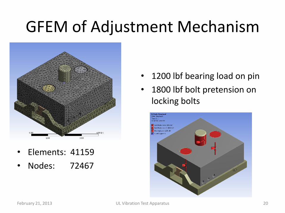
GFEM of Adjustment Mechanism
• \
• Elements: 41159
• Nodes: 72467
• 1200 lbf bearing load on pin
• 1800 lbf bolt pretension on locking bolts
February 21, 2013 UL Vibration Test Apparatus 20
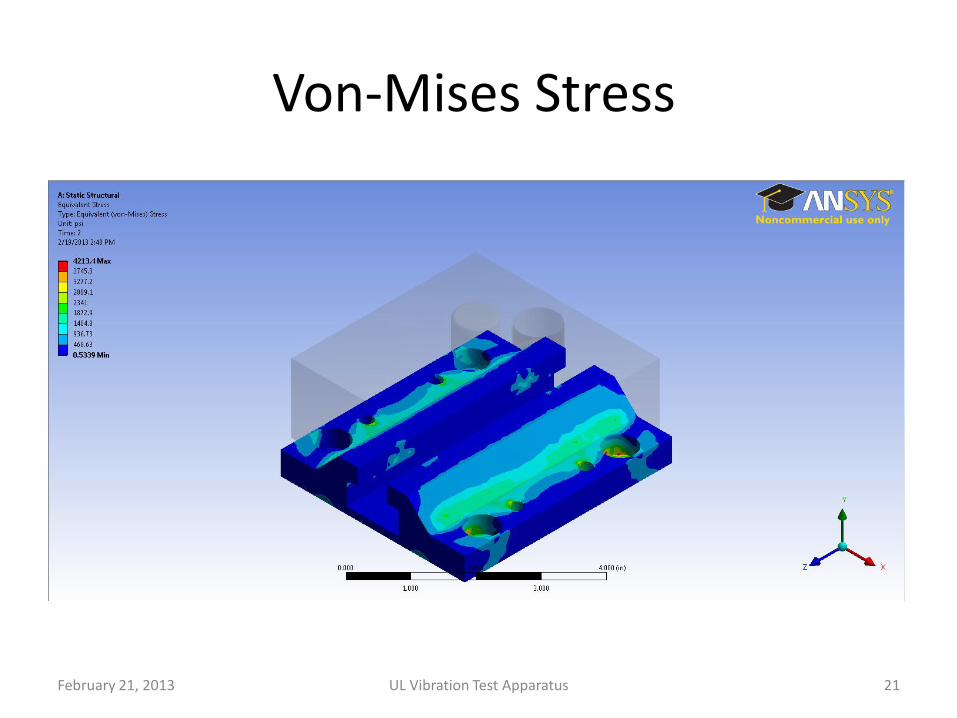
Von-Mises Stress
February 21, 2013 UL Vibration Test Apparatus 21

Von-Mises Stress
February 21, 2013 UL Vibration Test Apparatus 22

Adjustment Mechanism Displacement
February 21, 2013 UL Vibration Test Apparatus 23

Linear Motion Mechanism
February 21, 2013 UL Vibration Test Apparatus 24

Linear Motion Mechanism
• Keeps mechanisms enclosed for safety
• Prevents contaminates from getting into mechanisms
• Polycarbonate maintenance hatches on top and side of mechanism
• 1” diameter extension rod allows for more robust design without concern of buckling
February 21, 2013 UL Vibration Test Apparatus 25

February 21, 2013 UL Vibration Test Apparatus 26
Linear Motion Mechanism Calculations
Parameter Governing Equation Value Factor of
Safety
PV value each bearing 𝐹𝑁𝑆 =1
4𝐹𝐶
𝑌1 2+ 𝑚𝑠𝑙𝑖𝑑𝑒𝑟𝑔 2 29lbf 850lbf MAX
Shear force each bolt 𝐹𝑉 =1
16𝑁 2 + 𝑚𝑠𝑙𝑖𝑑𝑒𝑟𝑔 2 80lbf 1477
Rail deflection 𝑦𝑚𝑎𝑥 =𝑚𝑠𝑙𝑖𝑑𝑒𝑟𝑔𝑙
3
48𝐸𝐼 0.0088in -
Critical load for extension rod buckling
𝑃𝑐𝑟 = 𝐴 𝑆𝑦 −𝑆𝑦
2𝜋∙𝑙
𝑘
1
𝐶𝐸 1.2e5lbf 100
Axial deflection of extension rod
𝛿𝑚𝑎𝑥 =𝑁𝑙
𝐴𝐸 6.06e-4in -
Phi due to rail deflection
𝜑𝑚𝑎𝑥 = 𝑡𝑎𝑛−1𝑦𝑚𝑎𝑥
𝑙/2 0.05° 1° MAX

Linear Motion Mechanism Calculations
February 21, 2013 UL Vibration Test Apparatus 27
• Refer to Appendix A of handout for E, I, Sy, A
• Assumptions
• Rail deflection assumes a single load at the center of the rail (worst-case scenario)
• For buckling: C=4 (rigid end and free slider connection)
• N=1200lbf, msliderg=115lbf, l=22.25in
• Equations via Shigley’s Mechanical Engineering Design

Connecting Rod
• Peel-Away Brass Shaft Shims
• Shaft collars for holding bearings in place
February 21, 2013 UL Vibration Test Apparatus 28

Connecting Rod Analysis
February 21, 2013 UL Vibration Test Apparatus 29
Parameter Governing Equation Value Max Bearing
Load
Bearing Forces 𝑅𝐵𝑋 =
𝑁𝑐𝑜𝑠(𝜃)
2 600lbf 1300lbf
Bolt F.O.S. (Shear) 𝑛𝑉 =𝑆𝑃𝐴𝑏𝑜𝑙𝑡𝐹𝑉
1800 -
Bolt F.O.S. (Tension) 𝑛𝑇 =𝑆𝑃𝐴𝑏𝑜𝑙𝑡𝐹𝑇
72 -
Axial Force F.O.S. 𝑛 =𝑆𝑦𝑤𝑡
𝑁 62 -

GFEM Analysis of Connecting Rod
• Elements: 65557
• Nodes: 108327
February 21, 2013 UL Vibration Test Apparatus 30
Loading Case 1
Loading Case 2

Von-Mises Stress
February 21, 2013 UL Vibration Test Apparatus 31
Load Case 1
Load Case 2

Frame Design
February 21, 2013 UL Vibration Test Apparatus 32
44” 34”

Frame Design
February 21, 2013 UL Vibration Test Apparatus 33
Advantages: • Allows for a single technician to mount the luminaire • Extra support of U-channel decrease vibration of
system • Rubber pads in-between supporting beams help in
dampening the system • More space efficient than current design • *Approximately 44” X 34” footprint • Footprint may become larger due to resonate
frequency of design (to be tackled by next senior design group)

Motor Selection
• 3-Phase, 240V AC Motor • Steady-state period
– No acceleration of system
– 𝑇𝑟𝑒𝑞 = 𝑇𝑟𝑒𝑓𝑙𝑒𝑐𝑡𝑒𝑑 = 𝑟 𝐹𝑐𝑋1 sin 𝜃 + 𝐹𝑐
𝑌1 𝜃 • 𝑇𝑟𝑒𝑞 = 1.07 lbf∙ft • This corresponds to a motor horsepower of 0.41,therefore a 1hp motor is desired
– Where r= 1 64 in (stroke of crank), θ is angle of rotation of the motor (0 ≤ 𝜃 ≤ 2𝜋)
• Start-up period
– 𝑇𝑟𝑒𝑞 = 𝑇𝑟𝑒𝑓𝑙𝑒𝑐𝑡𝑒𝑑 + 𝐽𝑠𝑦𝑠𝛼
• Where: 𝐽𝑠𝑦𝑠 = 𝐽𝑟𝑒𝑓𝑙𝑒𝑐𝑡𝑒𝑑 + 𝐽𝑠ℎ𝑎𝑓𝑡 + 𝐽𝑑𝑖𝑠𝑐/𝑚𝑒𝑐ℎ𝑎𝑛𝑖𝑠𝑚 + 𝐽𝑚𝑜𝑡𝑜𝑟
• Assuming 50-60 seconds to reach 2000RPM, Treq ≈ 3 lbf∙ft
February 21, 2013 UL Vibration Test Apparatus 34

February 21, 2013 UL Vibration Test Apparatus 35
• At 2000RPM, a general purpose 1HP AC Baldor motor will produce 90oz∙ft ≈ 5.7lb∙ft torque
• Our estimated range for required start-up torque is highlighted in yellow
• At ~5.7lb∙ft torque, it is estimated that 2000RPM will be reached in approximately 30 seconds
• A variable-frequency drive will be used to obtain the required 2000RPM speed

Recommended Motor
February 21, 2013 UL Vibration Test Apparatus 36

February 21, 2013 UL Vibration Test Apparatus 37
Parameter Governing Equation Value Max Bearing
Load
Upper bearing force 𝑅𝐵1𝑋 =
𝑙2𝑙1
𝐹𝐶𝑋1
𝑙2𝑙1 − 1
2450lbf 3150lbf
Lower bearing force 𝑅𝐵2𝑋 =
𝐹𝐶𝑋1
𝑙2𝑙1 − 1
1225lbf 3150lbf
Se 𝑆𝑒 = 0.5𝑘𝑎𝑘𝑏𝑘𝑐𝑆𝑢𝑡 1.10e4psi -
F.O.S. Shaft 𝑛 =𝑆𝑒𝑆𝑦
𝑆𝑦𝜎𝑎 + 𝑆𝑒𝜎𝑚 10 -
F.O.S. Key 𝑛𝐾𝐸𝑌 =𝑆𝑦𝑤𝑙𝑟
𝑇𝑀𝑂𝑇𝑂𝑅 39 -
• Where ka, kb and kc are Marin factors for surface condition, size, and loading conditions, respectively.
• l1=2 , l2=4 , σmin, σmax, Sy, Sut can be found in Appendix
𝜎 𝑎 =𝜎𝑚𝑎𝑥 − 𝜎𝑚𝑖𝑛
2 𝜎 𝑚 =
𝜎𝑚𝑎𝑥 + 𝜎𝑚𝑖𝑛
2
Lubrication
• Drive Shaft Bearings: Double sealed flange mount bearings with easy access grease zerk fittings.
• Linear Bearings: Double sealed closed bearings with easy access grease zerk fittings.
• Crank Arm Bearings: Double Sealed roller bearings pre-packed with grease . Easy access for lubrication by taking off Polycarbonate cover.
February 21, 2013 UL Vibration Test Apparatus 38
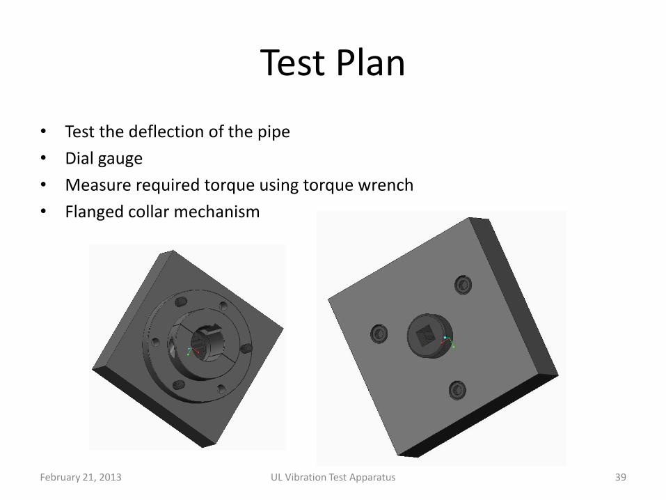
Test Plan
• Test the deflection of the pipe
• Dial gauge
• Measure required torque using torque wrench
• Flanged collar mechanism
February 21, 2013 UL Vibration Test Apparatus 39

Part Part Description Supplier Purchase # Qty. Pkg. Qty. Unit Price Price
Dowel 1/2"D X2" Alloy Steel MSC MSC#73079030 2 1 4.34 8.68
Dowel 1/4"D X 3/4" Alloy Steel MSC MSC#06024079 2 100 17.76 17.76
Dowel 1/4"D X 1" Alloy Steel MSC MSC#06024103 13 100 20.56 20.56
Dowel 1/4"D X 1.5" Alloy Steel MSC MSC#06024152 36 100 24.83 24.83
Dowel 3/4"D X 2" Alloy Steel MSC MSC#00328922 2 1 8.09 16.18
Nut Grade 8 Steel Nylon-Insert Hex Locknut Znc-Yellow Pltd, 1/2"-13 Thrd Sz, 3/4" W, 19/32" H McMaster-Carr MMC#97135A250 4 10 4.44 4.44
Nut Grade 8 Steel Nylon-Insert Hex Locknut Znc-Yellow Pltd, 3/8"-16 Thrd Sz, 9/16" W, 29/64" H McMaster-Carr MMC#97135A230 8 100 4.14 4.14
Screw Black-Oxide Alloy Steel Socket Head Cap Screw 1/2"-13 Thread, 2-3/4" Length McMaster-Carr MMC#91251A723 2 5 5.86 5.86
Screw Black-Oxide Alloy Steel Socket Head Cap Screw 1/2"-13 Thread, 3" Length McMaster-Carr MMC#91251A724 2 5 5.94 5.94
Screw Black-Oxide Alloy Steel Socket Head Cap Screw 1/4"-20 Thread, 2" Length McMaster-Carr MMC#91251A550 4 25 5.51 5.51
Screw Black-Oxide Alloy Steel Socket Head Cap Screw 3/8"-16 Thread, 2-1/4" Length McMaster-Carr MMC#91251A633 8 25 9.21 9.21
Screw Black-Oxide Alloy Steel Socket Head Cap Screw 1/4"-20 Thread, 3/4" Length McMaster-Carr MMC#91251A540 18 50 6.96 6.96
Screw Black-Oxide Alloy Steel Socket Head Cap Screw 1/4"-20 Thread, 1" Length McMaster-Carr MMC#91251A542 19 50 7.58 7.58
Screw Black-Oxide Alloy Steel Socket Head Cap Screw 3/8"-16 Thread, 7/8" Length McMaster-Carr MMC#91251A623 4 25 6.09 6.09
Screw Black-Oxide Alloy Steel Socket Head Cap Screw 1/4"-20 Thread, 1-1/4" Length McMaster-Carr MMC#91251A544 16 50 11.03 11.03
Set Screw Alloy Steel Flat Point Socket Set Screw 1/2"-13 Thread, 1-1/4" Length McMaster-Carr MMC#94105A715 1 5 9.87 9.87
Die Spring Screw Die-Spring Screw Cap 9/16"-18 Thread, 1/4" Hex, 5/16" Thickness McMaster-Carr MMC#96235K700 2 1 2.54 5.08
Nylon Bushing Nylon Bearing Flanged, for 1/2" Shaft Dia, 5/8" OD, 3/8" Length McMaster-Carr MMC#6389K419 2 1 5.54 11.08
Drive Shaft Fully Keyed Precision Drive Shaft W/Cert 1" OD, 1/4" Keyway Width, 12" Length McMaster-Carr MMC#8488T84 1 1 34.06 34.06
Shim Wide-Rim Zinc-Plated Steel Shim .075" Thick, 1" ID, 1-1/2" OD McMaster-Carr MMC#97669A330 2 25 5.82 5.82
Key Steel Machine Key Oversized w/ Square Ends, 1/4" Square, 1" Length McMaster-Carr MMC#98870A395 1 10 5.1 5.1
Flanged Shaft Collar Mounting Flange One-Piece Steel Shaft Collar 1" Bore, 2" Collar OD, 1" Overall Width McMaster-Carr MMC#9684T4 1 1 38.13 38.13
T Block Black-Oxide Steel Full-Thread T-Slot Nut 1/2"-13 Thread Size, for 5/8" Slot Width McMaster-Carr MMC#94750A584 2 1 3.17 6.34
Lock Washer Zinc-Coated Steel Wedge Lock Washer 1/2" Screw Size, .77" OD, .10" Thick McMaster-Carr MMC#91074A133 2 10 9.32 9.32
spring Type 302 Stainless Steel Compression Spring .750" Length, .500" OD, .062" Wire Diameter McMaster-Carr MMC#1986K118 2 6 4.76 4.76
Shaft Collar Two-Piece Shaft Collar with Wrench Flats 1" Bore, 1-3/4" Outside Diameter, 1/2" Width McMaster-Carr MMC#9746T4 1 1 7.17 7.17
Extension Rod Steel Drive Shaft 1" OD, 24" Length McMaster-Carr MMC#1346K38 1 1 40.82 40.82
Linear Rail Hardened Precision Steel Shaft 1" Diameter, 18" Length McMaster-Carr MMC#6061K45 2 1 21.18 42.36
Linear Bearing High-Speed Pillow-Block Linear Sleeve Bearing Closed, for 1" Shaft Diameter McMaster-Carr MMC#6674K16 4 1 93.37 373.48
Pin Collar Two-Piece Clamp-on Shaft Collar Steel, 3/4" Bore, 1-1/2" OD, 1/2" Width McMaster-Carr MMC#6436K16 2 1 4.46 8.92
Shaft Support Quick-Access Base Mount Shaft Support for 1" Shaft OD McMaster-Carr MMC#1865K6 6 1 24.57 147.42
Peel Away Shim 1 Peel-Away Brass Shim .032" Thick, 3/4" ID, 1-1/8" OD McMaster-Carr MMC#90805A164 3 1 6.8 20.4
Peel Away Shim 2 Peel-Away Brass Shim .062" Thick, 3/4" ID, 1-1/8" OD McMaster-Carr MMC#90805A184 1 1 9.17 9.17
Ball bearing High-Load Steel Ball Bearing Dbl Sealed, for Shaft Dia 3/4" X 1-3/4" OD X 1/2" W McMaster-Carr MMC#2780T3 2 1 17.85 35.7
Flange Mount Bearing Cast Iron Flange-Mounted Steel Ball Bearing 4-Bolt SQ-Flange, for 1" Shaft Diameter McMaster-Carr MMC#5967K84 2 1 41.97 83.94
1053.71
Hardware & Standard Parts
Hardware and Standard Parts Total:
February 21, 2013 UL Vibration Test Apparatus 40

Part Part Qty. Part Description Supplier Purchase # Qty. Unit Price Price
Alignment Block 1
Adjustment Screw Plate 1
Spring Plate 1
Adjustment Base 1 12"X4"X1" 1018 Steel MSC MSC #03913977 1 55.32 55.32
Adjustment Slider 1 12X4X1.5 1018 Steel MSC MSC #03915626 1 83.64 83.64
Circular Plate 1 8"D X 3/4" 304 Stainless Steel MSC MSC #75335299 1 154.7 154.7
Side Plates 2 Multipurpose O1 Tool Steel Tight-Tolerance Flat Stock, 1/2" X 8", 1-1/2'L McMaster-Carr MMC#9516K718 2 163.23 326.46
Front Plate 1 Low-Carbon Steel Sheet 1/2" Thick, 8" X 12", Ground Finish McMaster-Carr MMC#1388K371 1 88.1 88.1
Support Rib 2 Low-Carbon Steel Tight-Tolerance Rect Bar 1/2" Thick, 2-1/2" Width McMaster-Carr MMC#9517K526 2 29.96 59.92
Platform Plate 1 Multipurpose 4140/4142 Alloy Steel Oversized Sheet, 1/2" Thick, 10" X 12" McMaster-Carr MMC#4473T13 1 84.78 84.78
Back Support Rib 2 Low-Carbon Steel Tight-Tolerance Rect Bar 1/2" Thick, 2" Width McMaster-Carr MMC#9517K524 2 27.01 54.02
Riser Block 4 Low-Carbon Steel Tight-Tolerance Rect Bar 1" Thick, 1" Width McMaster-Carr MMC#9517K595 1 52.76 52.76
Polycarbonate Sheet 1 1
Polycarbonate Sheet 2 1
Crank Arm 1 Low-Carbon Steel Tight-Tolerance Rect Bar 1/2" Thick, 3" Width McMaster-Carr MMC#9517K528 1 35.74 35.74
Base Plate 1 Low-Carbon Steel Sheet 1" Thick, 24" X 24", Ground Finish McMaster-Carr MMC#1388K581 1 416.39 416.39
Extension Rod 1 Steel Drive Shaft 1" OD, 24" Length McMaster-Carr MMC#1346K38 1 40.82 40.82
Pin Block 1 Low-Carbon Steel Sheet 1-1/2" Thick, 4" X 4", Ground Finish McMaster-Carr MMC#1388K704 1 44.76 44.76
1657
Raw Materials
Raw Material:
66.56
12"X4"X.5" 6061 Aluminum MSC MSC #86466356 1 93.03 93.03
Impact-Resistant Polycarbonate Sheet 1/4" Thick, 24" X 36", Clear McMaster-Carr MMC#8574K285 1 66.56
February 21, 2013 UL Vibration Test Apparatus 41

Part Description Supplier Purchase # Qty. Pkg. Qty. Unit Price Price
1/2" x 2.5" 13 Bolt McMaster-Carr MMC#92327A308 36 1 4.11 147.96
1/2" 13 Nut McMaster-Carr MMC#90499A033 52 50 7.83 15.66
3/4" 10 Bolt McMaster-Carr MMC#92327A362 8 1 8.03 64.24
3/4" 10 Lock Nut McMaster-Carr MMC#90630A135 8 5 4.45 8.90
1/2" x 4" 13 Bolt McMaster-Carr MMC#92327A314 16 1 6.00 96.00
Pipe Flange McMaster-Carr MMC#6806K125 1 1 30.00 30.00
5/8" 11 Bolt McMaster-Carr MMC#92327A332 5 1 5.08 25.40
5/8" 11 Nut McMaster-Carr MMC#90499A832 5 50 12.04 12.04
U Channel Metals Depot C21025 1 1 157.48 157.48
H Beam Metals Depot B2413 6 1 107.50 645.00
3' Crossbeam McMaster-Carr MMC#8910K58 5 1 102.87 514.35
Rubber Damper McMaster-Carr MMC#9023K26 2 1 20.47 40.94
H Beam Feet McMaster-Carr MMC#8910K58 1 1 102.87 102.87
L Bracket McMaster-Carr MMC#8910K302 1 1 256.91 256.91
2117.75
Frame Components
Frame Components Total:
February 21, 2013 UL Vibration Test Apparatus 42

Part Part Description Supplier Purchase # Qty. Price
Flanged Shaft Collar Mounting Flange One-Piece Steel Shaft Collar 1" Bore, 2" Collar OD, 1" Overall Width McMaster-Carr MMC#9684T4 1 38.13
Socket Drive 3/8" Square Drive Socket 12-Point Std, 3/4" Sz, 1-1/8" L O'all, Black Fnsh McMaster-Carr MMC#5484A49 1 5.28
Dial Indicator Mitutoyo Dial Indicator Continuous, 1-5/8" Dia, 0-0.250" Range, 1410S-10 McMaster-Carr MMC#2246A41 1 95.23
138.64
Test Materials
Test Material Total:
Part Part Description Supplier Purchase # Price
Motor 1Hp 3450RPM, 3PH, 60Hz, 230/460V Baldor M3545 472
Motor Base Adjustable NEMA Motor-Mount Base for NEMA 56 Frame McMaster-Carr MMC#62035K21 19.02
491.02
Motor Components
Motor Components Total:
February 21, 2013 UL Vibration Test Apparatus 43

-Brinkman Lab Machining: $90 per hour -Only part of the frame may be developed for test purposes -Unexpected tooling costs that may arise -Need for remaking parts (we are not expert machinists)
Cost Category Cost
Hardware & Standard Components 1053.71
Raw Materials 1657.00
Frame Components 2117.75
Test Materials 138.64
Motor Components 491.02
Est. Machining Costs 800.00
Est. Unexpected Costs 800.00
Total: 7058.12
Cost Breakdown
February 21, 2013 UL Vibration Test Apparatus 44

February 21, 2013 UL Vibration Test Apparatus 45

February 21, 2013 UL Vibration Test Apparatus 46

Questions For Customer
• NPT Pipe Length
• Pipe Collar
• Testing with Lamp
• Financing logistics of Project
February 21, 2013 UL Vibration Test Apparatus 47

Open Discussion
• Any questions?
• Design concerns not discussed?
• Feed back on work done to this point?
• Validity of our Design?
• Do we have approval to purchase materials and begin developing the product?
February 21, 2013 UL Vibration Test Apparatus 48

Appendix UL Test Standard and Project Background

Project Background
• To pass safety requirements for certification the luminaires must meet a series of Underwriters Laboratories Inc. Standards.
• A Vibration Test Stand is currently being used by Cooper Crouse-Hinds to test pendant mount luminaires according to section 33 of the UL844 Standard.
• The Current Vibration Test Stand is outdated, has multiple design flaws, and design documentation and drawings are non-existent.
• Cooper Crouse-Hinds would like a new modernized Vibration Test Stand to be developed that addresses some of the design flaws of the current system while maintaining UL844 Test Standards. This new Design must also have a LabView interface and control capability integrated into the system.
February 21, 2013 UL Vibration Test Apparatus 50

Design Goals over Winter/Spring MSD
Note: It has been decided that this apparatus will be developed in multiple Senior Design Sequences.
• Provide customer with two design concepts for vibration mechanism
• Develop a final design of the vibration mechanism.
• Design a steel test frame that will support the vibration mechanism and the vertical conduit.
• Design but do not develop steel frame for entire vibration test machine.
• Develop a full set of engineering drawings.
• Calculate and select the required drive train system components.
• Purchase materials, machine components, and assemble the vibration mechanism and test frame.
• Test the mechanism to ensure that it meets 1/32” deflection requirement
February 21, 2013 UL Vibration Test Apparatus 51

Summary of UL844 Vibration Test Standard
LUMINAIRES FOR USE IN HAZARDOUS (CLASSIFIED) LOCATIONS – UL 844
Section 33 – Vibration Test Standards
• Luminaire is to be subjected to 35 hours of vibration testing.
• Luminaire assembly is to be attached to a 26-1/2” long conduit via NPT threading. The other end of the NPT threaded pipe is to be secured to the hub of a rigid mounting frame so that the conduit hangs vertically. The conduit should correspond to the smallest size of threaded conduit hub that is designed to attach to the Luminaire being tested.
• The horizontal force to be applied to the system in order to obtain the deflection must me located 4” above the location of the conduit where the Luminaire attaches.
• The deflection must be 1/32” with 1/16” total deflection per cycle.
• The system must run at 2000 cycles/min.
February 21, 2013 UL Vibration Test Apparatus 52

UL844 Vibration Test Standard
February 21, 2013 UL Vibration Test Apparatus 53

Design Flaws Associated with Original Design
February 21, 2013 UL Vibration Test Apparatus 54
• Difficult for one technician to set up test
• Lubricant not contained
• Machine components exposed to contaminants
• Belts used (slipping)
• Uses single speed motor with a speed reducer
• Frequency adjustment dial held in place with rope
• No displacement adjustment
• Attachment collar may experience minor buckling
• Does not accounted for part wear and tolerance stack up

Customer Design Needs
Need # Importance High 3 – 2 – 1 Low
Design Criteria Measure of Effectiveness
CN1 3 Obtain vibration frequency of 2000 cycles/min Stroboscope
CN2 3 Create displacement of 1/32” at 22.5” bellow pipe flange Dial Gauge
CN3 2 Adjustment of attachment collar position for perpendicularity ___
CN4 2 240 V electrical input ___
CN5 2 System envelope size is maintained or decreased from original system ___
CN6 1 Mounts to current anchor points in floor ___
CN7 3 Capability to adjust for different pipe sizes ___
CN8 1 Use current flange mounting for pipes ___
CN9 2 Design in an easily removable collar ___
CN10 3 Will support multiple types of Luminaires ___
CN11 2 Easy to mount the Luminaires 1 Technician can run entire test
CN12 1 Ease of lubrication ___
CN13 2 Containment of Lubricant Look for leaking of Lubricant
CN14 3 System to not run near resonate frequency Does not shake itself apart
CN15 1 Minimize noise of system Under 85 decibels (OCIA standard for requiring
ear protection)
February 21, 2013 UL Vibration Test Apparatus 55

PUGH Matrix: Rotational to Linear Motion Mechanism
February 21, 2013 UL Vibration Test Apparatus 56
# Evaluation Criteria Crankshaft Eccentric Shaft Scotch Yoke Cam & Follower
1 Robustness s + + -
2 Cost + - + s
3 Design Simplicity s + s s
4 Adjustability s - + s
5 Component Wear s s - -
6 Ease of Lubrication - + - -
7 Part Replacement s - + +
8 Accuracy/Tolerance Stack-up + + + -
9 Ease of Maintenance s s + s
10 Ease of Manufacture + - + s
11 In-house Manufacture + - + s
12 Ease of Assembly s s s s
13 Noise/Vibration + + - s
14 Safety s + s s
4 1 5 -3
Rotational to Linear Conversion
Sum

PUGH Matrix: Slider Mechanism
February 21, 2013 UL Vibration Test Apparatus 57
# Evaluation Criteria Pillow Block Bearings Viscous Fluid Layer Roller Bearings w/wheels Linear Bearings on rails
1 Robustness + + S +
2 Cost S + S S
3 Design Simplicity S S - S
4 Component Wear + - S +
5 Ease of Lubrication + + S +
6 Containment of Lubricant S - S +
7 Part Replacement + - + +
8 Ease of Maintenance + S + +
9 Ease of Manufacture + + S +
10 In-house Manufacture S S S S
11 Ease of Assembly S S S S
12 Noise/Vibration S - S S
6 0 1 7
Slider Mechanism
Sum

PUGH Matrix: Displacement Adjustment Mechanism
February 21, 2013 UL Vibration Test Apparatus 58
# Evaluation Criteria Screw Linear Actuator Pivot Cam slider w/ tightening bolt
1 Robustness - + -
2 Cost - + +
3 Design Simplicity - + +
4 Part Replacement - + S
5 Accuracy of Adjustment + - -
6 Ease of Manufacture - S +
7 In-house Manufacture - + +
8 Ease of Assembly - + +
9 User Friendly + S S
-5 5 3
Displacement Adjustment Mechanism
Sum

February 21, 2013 UL Vibration Test Apparatus 59
Risk Assessment

February 21, 2013 UL Vibration Test Apparatus 60