
Manual cms ( central management system ) / Video Viewer for AVTECH DVR

System 800xA
Interlock Viewer for AC800MUser Manual
System Version 5.1

3BDA035401R5105EN_Interlock Viewer 2/46
Purpose
The purpose of this document is to describe the PC Interlock Viewer for System 800xAand AC800M Connect. The PC Interlock Viewer is the successor of the PC InterlockDisplay with new features.
Notice
This document contains information about one or more ABB products and may includea description of or a reference to one or more standards that may be generally relevantto the ABB products. The presence of any such description of a standard or referenceto a standard is not a representation that all of the ABB products referenced in thisdocument support all of the features of the described or referenced standard.
This document and parts thereof must not be reproduced or copied without writtenpermission from ABB, and the contents thereof must not be imparted to a third partynor used for any unauthorized purpose.
Trademarks
All rights to copyrights, registered trademarks, and trademarks reside with theirrespective owners.
Copyright © 2015 by ABB.
All rights reserved.
Release: 2014-06-11
Document Number: 3BDA035401R5105EN_Interlock Viewer

Table of contents
3BDA035401R5105EN_Interlock Viewer 3/46
Table of contents
1. About This Book ......................................................................................... 41.1 General ........................................................................................... 41.2 Use of Caution, Information, and Tip Icons ...................................... 41.3 Terminology .................................................................................... 4
2. How to get started ....................................................................................... 52.1 Program Installation ........................................................................ 62.2 System Extension Loading .............................................................. 62.3 Upgrading former PC AC800M Interlock Display installations.......... 92.4 The Interlock Viewer Uploader Tool............................................... 122.5 Updating control data for Interlock Viewer ..................................... 142.6 Limitations ..................................................................................... 15
3. Customizing Interlock Viewer .................................................................. 173.1 Customizing Generation behavior and layout ................................ 173.2 Customize common setting ........................................................... 183.3 Customizing Generation settings ................................................... 183.4 Customize Layout settings ............................................................ 263.5 Customize object type definitions .................................................. 303.6 Data type handling ........................................................................ 333.7 Configuring the module presentation of the PC Interlock Viewer ... 353.8 Exclude module types from content analyze .................................. 363.9 Define Colors ................................................................................ 37
4. Operating Interlock Viewer ....................................................................... 39
How to get started
3BDA035401R5105EN_Interlock Viewer 4/46
1. About This Book
1.1 GeneralThis instruction describes how to use the Interlock Viewer for AC800M.
The aspect type Interlock Viewer for AC800M shows the binary incoming interlock andpriority command criteria for the selected object types motor or valve. Depending onthe status of the variable, criteria that are met are shown in green and criteria not metare shown in red. Priority and interlocking parameters can be used to control thebehavior of the process objects in certain situations, for example, stopping an objectfrom running into a certain state or forcing it into a certain state.
1.2 Use of Caution, Information, and Tip IconsThis publication includes Caution and Information where appropriate to point outsafety related or other important information. It also includes Tip to point out usefulhints to the reader. The corresponding Function Designer Components should beinterpreted as follows:
Caution icon indicates important information or warning related to the conceptdiscussed in the text. It might indicate the presence of a hazard which couldresult in corruption of software or damage to equipment/property.
Information icon alerts the reader to pertinent facts and conditions.
Tip icon indicates advice on, for example, how to design your project or how touse a certain function
Although Caution hazards are associated with equipment or property damage, itshould be understood that operation of damaged equipment could, under certainoperational conditions, result in degraded process performance leading to personalinjury or death. Therefore, comply fully with all Caution notices.
1.3 TerminologyA complete and comprehensive list of Terms is included in the Industrial IT, 800xA -System, Engineering Concepts instruction (3BDS100972).
The following listing includes terms and definitions as they apply to the 800xA systemand specifically to the Interlock Viewer for AC800M.

How to get started
3BDA035401R5105EN_Interlock Viewer 5/46
2. How to get startedThe Interlock Viewer system extension consists of the following sw package.
n ABB PC Interlock Viewer 5.1-1/8 (Build: 5.1.5637.13935)
Execute the following steps to get it installed.
n Install Interlock Viewer program – refer to 2.1
n Load Interlock Viewer programs – refer to chapter 2.2
n Select a start object in the object browser and generate the Viewer Aspectsrefer to chapter 2.4
n For a start, customizing the Interlock Viewer settings is not needed. - refer tochapter 3
n Select Interlock Viewer window by means of a locked motor or valve faceplateor by means of the faceplates context menu. – refer to chapter 4

How to get started
3BDA035401R5105EN_Interlock Viewer 6/46
2.1 Program InstallationInstall the Interlock Viewer for AC800M Setup on all 800xA aspect server andall engineering client nodes.
1. Start the program “Setup.exe” from the installation folder. Follow theinstructions of the Installation Wizard.
2. Activate the option „ ABB PC Interlock Viewer 5.1-1/8“.Clicking Install andsome Next buttons starts the installation.
3. You can view the successful installation via the log file.
2.2 System Extension LoadingAfter completing the installation procedures on all 800xA nodes, load the InterlockViewer for AC800M system extension. This procedure has to be executed once.
Make sure that the 800xA System, including the system extensions for theneeded control libraries has been loaded prior to starting the followingprocedure.
Loading the system extension ABB PC Interlock Viewer 5.1-1/8:
1. Start the 800xA Configuration Wizard.
Start -> All Programs -> ABB Industrial IT 800xA -> System -> ConfigurationWizard.
2. When the dialog appears select System Administration as type ofconfiguration and confirm your selection with Next.

How to get started
3BDA035401R5105EN_Interlock Viewer 7/46
3. Select your 800xA System Name and continue with Next.
4. Choose System Extension Load to initially load the ABB PC Interlock Viewerextension. Continue with Next. When updating ABB PC Interlock Viewer,choose System Extension Maintenance

How to get started
3BDA035401R5105EN_Interlock Viewer 8/46
5. Move extension ABB PC Interlock Viewer to the right list. Clicking Next bringsthe next dialog.
6. Confirm the start of the loading process with Finish.
7. The following window appears after the completion of the load operation.Proceed with Finished to the Configuration Wizard.
8. Exit closes the Configuration Wizard dialog.

How to get started
3BDA035401R5105EN_Interlock Viewer 9/46
2.3 Upgrading former PC AC800M Interlock Display installationsThis task should be executed by someone who is familiar with 800xA administration. Itwill last approximately 1 to 2 hours. Please follow this instruction thoroughly. Misusecan damage the system configuration. Alternatively we offer our services. Contact yourlocal ABB representative or e-mail us via mailto:[email protected]
Both versions can run in parallel. The PC AC800M Interlock Display shouldonly be removed if all new Interlock Viewer aspects are generated and allreferences from graphics and faceplates are changed to the new InterlockViewer aspects.
To upgrade the ABB PC AC800M Interlock Display to the new PC Interlock Viewerfollow the upgrade steps.
§ Install the PC Interlock Viewer software as described in chapter 2.1.
§ Load the PC Interlock Viewer system extension as described in chapter 2.2
§ Start the Uploader tool as described in chapter 2.5.
When the Uploader tool is first started, a window appears which allowstransferring the available “old” configuration aspects (Interlock Display) into thenew Interlock Viewer aspects (if there is any configuration data that is notalready part of the common or library specific configuration).Select the items (object types, data types and modules) you want to transfer tothe Interlock Viewers project definition and click OK.If you have selected any object type, the needed aspects will also be created onthe object type. In case the Override functionality is used, answers the question“Proceed also Override State aspect” with “Yes”.
§ Select each project (or applications) in your system and perform an upload toupdate the Interlock Viewer aspects.
§ Add the PC Interlock Viewer aspect category to the filter settings used foroperation and engineering.
§ Open one Interlock Viewer aspect and in parallel an Interlock Display andcompare the indicated logic. This is to ensure that the settings of the InterlockViewer are equal to the current Interlock Display configuration.
§ Change all references in graphics and faceplates to the new Interlock Viewer.For the PC Library objects this can be done by importing the adapted faceplatesand graphic elements or updating the PC Toolkit Library to version 5.1-3 orabove.
§ Remove all interlock display aspects from your system, starting at the objecttypes. It is mandatory to create an 800xA backup before execute these steps.

How to get started
3BDA035401R5105EN_Interlock Viewer 10/46
Delete the Interlock Display aspect on each object type in the object typestructure. This can be done by using the Find Tool with the settings AspectCategory = “PC AC800M Interlock Display” and Structure = “Object TypeStructure”
As it is allowed to have instances also in the Object type structure (as part ofother object types), it is mandatory to delete the aspects for basic object typesfirst. Select only those names which represent object types and no instances.Deletion may also be aborted when objects are reserved by any user. Sosearch them and release them first before deletion.
2. Delete the Interlock Display aspect on each instance. This can be doneby using the Find Tool with the settings Aspect Category = PC AC800MInterlock Display.
If the following message occurs during deletion
Open the Consistency Check tool and insert the object(s) by drag anddrop to the left pane of the consistency check tool. Click the Checkbutton.

How to get started
3BDA035401R5105EN_Interlock Viewer 11/46
Select the reported error messages, open the context menu and click“Repair aspect”. Accept the following message box with click on Yes.
Repeat step 1 and 2 also for all aspects of category “PC AC800M InterlockUploader” (if available in the 800xA system).
3. Remove the definition of the Interlock Display aspect type and categorydefinition from the 800xA system.Use the Plant Explorer Workplace (or Engineering Workplace) and go tothe Aspect System Structure and navigate to the object “PC AC800MInterlock Display, Aspect System”. Select this object and delete it.
4. Remove the system extension entries from the 800xA system.
a. Navigate to the system definition in Admin Structure (locatedunder [Admin Structure]Administrative Objects/Domains) andopen the System Extensions aspect.Select the PC AC800M Interlock Display item in the upper paneand then select the first entry in the lower pane, open the contextmenu and click delete.
Answer the following message box with „No“ (Yes is notimplemented).
How to get started
3BDA035401R5105EN_Interlock Viewer 12/46
Repeat this step for each entry in the lower pane.
b. Navigate to the system extension object in the Admin structure([Admin Structure]Administrative Inventory/ObjectsObject/System Extension/PC AC800M Interlock Display) anddelete this object.
§ Uninstall interlock display on all nodes
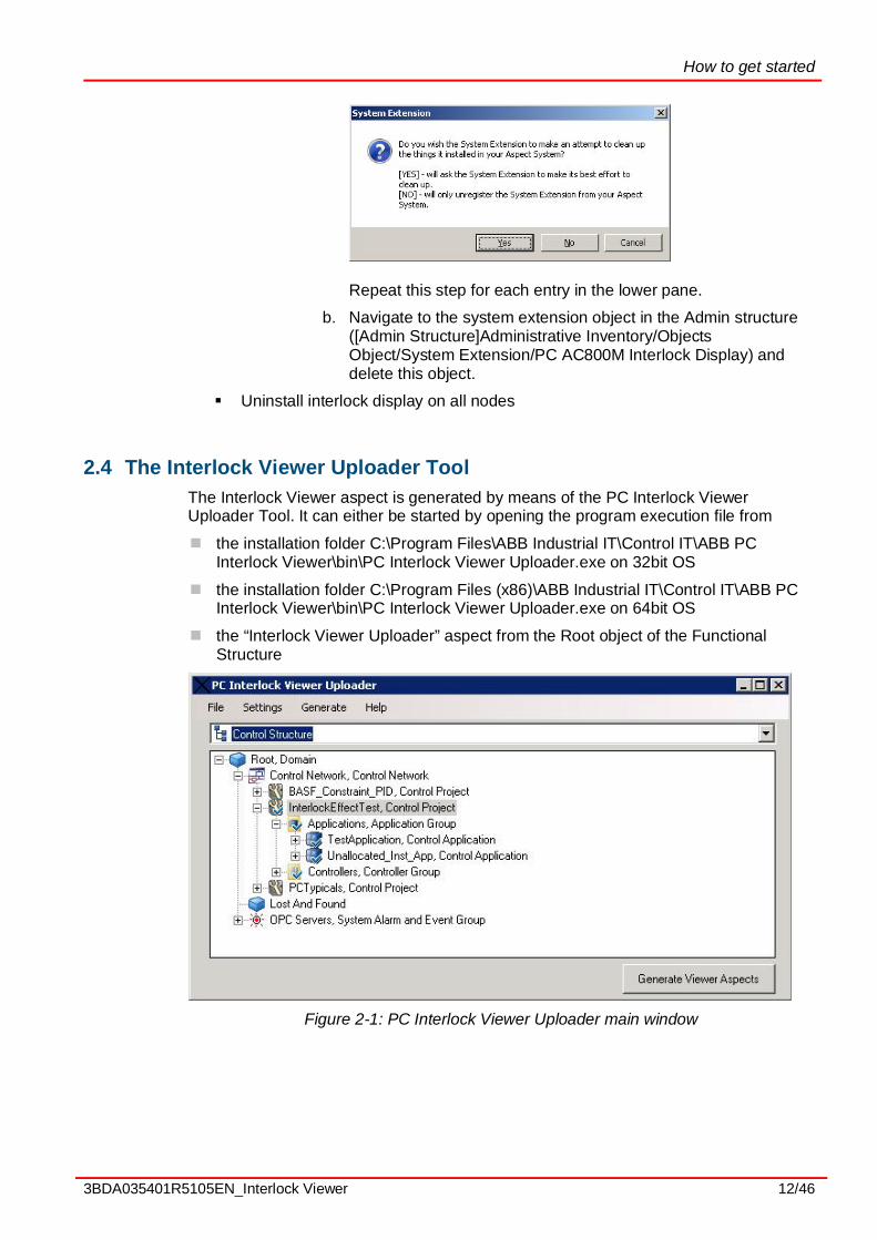
2.4 The Interlock Viewer Uploader ToolThe Interlock Viewer aspect is generated by means of the PC Interlock ViewerUploader Tool. It can either be started by opening the program execution file from
n the installation folder C:\Program Files\ABB Industrial IT\Control IT\ABB PCInterlock Viewer\bin\PC Interlock Viewer Uploader.exe on 32bit OS
n the installation folder C:\Program Files (x86)\ABB Industrial IT\Control IT\ABB PCInterlock Viewer\bin\PC Interlock Viewer Uploader.exe on 64bit OS
n the “Interlock Viewer Uploader” aspect from the Root object of the FunctionalStructure
Figure 2-1: PC Interlock Viewer Uploader main window

How to get started
3BDA035401R5105EN_Interlock Viewer 13/46
Select a valid start object and start generation
First select a start object in the object browser. Valid object types are Control Project,Control Application Group and all objects below. It is also possible to select a singleobject; in this case the generation of the Interlock Viewer aspect will only be performedfor this object. But the application data will always refresh (if any configuration changeis found) for the entire application where the object is located.
After a mouse click on the “Generate Viewer Aspects” button (or select menu Generate→ Generate Viewer Aspects) an options window shows up. Here you can set additionaloptions for aspect generation.
Figure 2-2: Aspect generation – Options
§ Select aspect types for update
o Update Interlock Viewer aspectsPerform the recreation of the contents of the Interlock Viewer aspects
o Update Effect Viewer aspectsPerform the recreation of the contents of the PC Effect Viewer aspects.This option is only available if the PC Effect Viewer system extension isinstalled (see document 3BDA035403 Effect Viewer for AC800M)
At least one option must be select in order to proceed!
§ Additional settings
o Force database updateForces an update of configuration data in the internal database, even ifno configuration change is detected during the check of the modificationdate.
o Update database with current configuration onlyIf set, the Uploader is updating the configuration data in the internaldatabase, but the viewer aspects will not refresh.
o Create additional data files for error analysisIf this option is set, some intermediate XML files are created in the Datasubdirectory (C:\Program Files\ABB Industrial IT\Control IT\ABB PCInterlock Viewer\bin\Data).This option should only be set on request by ABB service personnel.

How to get started
3BDA035401R5105EN_Interlock Viewer 14/46
A mouse click on the OK button starts analysis of the control application(s), the uploadof the configuration data (if needed) and the generation of graphics data of all InterlockViewer aspects located at the selected 800xA object and its child objects.
A progress window is shown, in which the upper bar indicates the overall progress andthe lower bar the progress of the current step. The text field contains the actions thatare executed as text.
Figure 2-3: Aspect generation – Progress dialog
The upload is finished if a completed message is shown and the Close button isenabled.The upload may abort either by clicking the Abort button or automatically due to anerror reported during upload. The abort request must be confirmed in the Abort dialog.It may take a while until the confirmation dialog is shown.
In case of an error, check the upload log file and session log file (available from themain window menu File → View last upload log and File → View session log) and mayneeded corrections or contact your service organization. The session log file containsmore detailed information.
2.5 Updating control data for Interlock ViewerAfter every configuration change (If interlock relevant configuration is changed or theobject has moved to another location in the control structure) an upload is necessary.The tool analyses the inputs of the interlock relevant ports (as described in “Defineupload settings”) of the object where the Interlock Viewer aspect is located.
The Interlock Viewer Uploader is analyzing the complete control application (where theselected object is located) and stores interim data in a local database. Prior to the startof the Interlock Viewer aspects generation, the modification dates of the aspects of thecurrent application will be checked against the last upload time and performs aconfiguration data upload from the CBM if necessary.
It is recommended that the upload should always run on one engineeringclient (or server).Analyzing an application or project may take some time depending of thecontents of the application.

How to get started
3BDA035401R5105EN_Interlock Viewer 15/46
Control Builder M must be installed on the client node in order to successfullylaunch the tool to generate or update the Interlock Viewer content.
Be sure that no reserved entities exist during the run of the Uploader tool! Theexecution may fail if an object is reserved by another user.
2.6 LimitationsThe Uploader tool has some limitations for reading and analyzing the currentconfiguration from Control Builder M. Configurations that exceed these limitations willeither not be displayed or do not work properly.
n Programs, Single Control Modules or Control Module types must be configured asFBD (function block diagram) or diagram code. The Function Designer createsFBD (for function diagrams based on single control modules) or diagram codeinside the CBM. Connections between Control Modules created by the CMD editoror manually by assigning variables in the connection window of a control moduleare possible.
n Limited support for structured text (ST) is available. Excluded from analysis arestatements like selections (if, case) and loops (for, while, repeat) and their innercode.
n Contents of control modules or function blocks that are marked as protected will notbe analyzed, even if the protection is currently overridden in the ControlBuilder M.
n The use of communication variables (IAC - Inter Application Communication) andMMS requires that the source application of a communication variable is analyzedprior the target application; otherwise the source is not show in the interlockviewer). Use the option “Update database with current configuration only” toanalyze the applications only before starting the “normal” generation of the interlockviewer aspects.
n The direction of control module parameters must be defined either by using thedirection entry on the control module parameter definition or by defining thedirection in the description (description starts with IN …, OUT …, etc). Thedefinition of the direction will be used prior to the definition in the parameterdescription.Parameters with direction “in_out” are analyzed as input parameters, except thedirection is defined in data type definition for each component (in the description) ofa structured data type! This can be overridden in the configuration settings (seechapter 3.5 Customize object type definitions).Please take care especially when using nested object types with mixed parameters(input and output values in the same parameter). It should not be used in order tocreate proper Interlock Viewer displays.
n Deleted or renamed applications must remove from the data base prior start a newupload. This can be done by delete the complete data base or the singleapplication using the “Delete database” or “Delete application from database” menuitem in the Generate menu.
n The code analysis will stop, if:

Customizing Interlock Viewer
3BDA035401R5105EN_Interlock Viewer 16/46
§ “Deep Search” option is not enabled and acontrol module or function block witha faceplate is found. The name and the port of object will be added to theinterlock display.
§ No source for a variable / connection was found in the uploaded configurationdata. This may happen if a variable is defined on an input without any source.The name and description of the variable will be added as variable to theinterlock display.
§ “Stop analyze at FD reference” is enabled:If function designer is used to configure the control logic and the Uploaderfound an external or communication variable.
§ The Function Designer is used to configure the control logic and an external orcommunication variable description ends with “#IVBreak” (case sensitive). Thisis used to break the code analysis at a defined point (normally used to simplifythe shown logic).
§ The module type found during the code analysis is listed in the “Stop analysison modules” list in the configuration (see chapter 3.8 Exclude module typesfrom content analyze).

Customizing Interlock Viewer
3BDA035401R5105EN_Interlock Viewer 17/46
3. Customizing Interlock Viewer
3.1 Customizing Generation behavior and layoutThe contents and generation settings for the Interlock Viewer are stored within the800xA system.
There are several aspects located at the object “[Object Type Structure]ObjectTypes/PC Interlock Viewer Definitions/PC Interlock Viewer Settings”.
Aspects of category “PC Interlock Settings” contain solution specific configurationsettings for OGP REUSE Solution Library for Oil & Gas projects (ABB OGP Norway)and PC Library for the Process Industries (ABB OGP Germany). These aspects mustnot be changed by a project team. Original aspects that are customized will beoverwritten when upgrading the Interlock Viewer software
An additional aspect of category “PC Interlock User Settings” allows furthercustomization. This aspect contains project specific configuration data. Project specificsettings for the same object type and port are higher prior than the library settings.
To transfer the project settings from one system to another system export the “IVproject settings” aspect from the source system and transfer it to the target system
To edit the settings open the Interlock Uploader tool and select “Settings” -> “EditInterlock Viewer settings”. The configuration dialog is shown.
Change and create library specific configuration settings (Developer mode)
As default only the Project Defined settings can be changed. Library developer canaccess the library specific configuration settings by entering a password. For passwordsend a request to [email protected]. Select the menu“Settings” → “Developer mode” in the Interlock Uploader main window and enter thepassword to enable the developer mode.
After enabling the developer mode, each predefined configuration setting can bechanged. Select the current scope drop-down box (in the lower left corner of theconfiguration window) and select the configuration that should change.
Figure 3-1: Change current configuration setting for editing
The “Add new …” choice allows creating a new setting. The name specified is also thename of the configuration aspect. Only numbers, letters and some other characters(space, underscore) are allowed in the setting name.
Existing configuration settings are deleted by removing the configuration aspect for800xA.

Customizing Interlock Viewer
3BDA035401R5105EN_Interlock Viewer 18/46
Library specific settings are valid for object types, data types and modules. Generationand layout settings are always project specific.
3.2 Customize common settingCommon settings will the defined basic behavior of the uploader tool.
Figure 3.2 Interlock Viewer Common settings
Analyze structured text code blocks
This will enable the analyses of structure text code blocks during the upload of acontrol application.
Automatic compact the data base
This will enable the automatic compacting of the data base after upload of applicationcontents. Depending on the size of the data base this may take some minutes.
To avoid unnecessary waiting time if planned to upload more than one application inseparate steps, it is possible to disable the automatic data base compacting. If this isdisabled it is possible to compact the data base manually by the menu Generate –Compact data base.
3.3 Customizing Generation settingsThe “Generation settings” can be modified to the project needs.
Modification on the Generations settings require a recreation of the Interlock Vieweraspects by performing a new upload.

Customizing Interlock Viewer
3BDA035401R5105EN_Interlock Viewer 19/46
Figure 3-3: Interlock Viewer Generation settings
Stop analyze at FD reference
The Interlock Viewer Uploader is also able to analyze configurations that might consistof more than the current POU (Diagram, Single Control Module).
The choice “Stop analyze at FD reference” will create data for the current FunctionDesigner diagram only. Input references from other diagrams are shown as thevariable name.
By activating this option, the same behavior on the upload is achieved as it was in theformer PC Interlock Display for AC800M 5.0-3.
Figure 3-4: Interlock Viewer with setting Stop analyze at FD reference = True

Customizing Interlock Viewer
3BDA035401R5105EN_Interlock Viewer 20/46
Figure 3-5: Interlock Viewer with setting Stop analyze at FD reference = False
Deep search
Normally the code analysis is stopped if an object with faceplate was found. Then areference to the objects output is placed as input variable for the Interlock Viewer.
In some configurations it might be useful, to see the complete path from the currentinterlock input up to the objects that have impact on the interlock. This can be achievedby setting the “Deep search enabled” option.
If this option is set, the code analyze will not stop at modules with a faceplate, it willalso be examined as a “normal” module and its inputs will also be analyzed. Such amodule is displayed in the logic view as a module with a 3D frame. A mouse click onthis frame opens the default aspect of this 800xA object (normally the faceplate). Witha right mouse click the context menu is shown.
Deep search may result in very complex logic views. In order to reduce thecomplexity, constant inputs of modules will be hidden and the input values ofthe Interlock Viewer will be the first module output in the logic chain (if any).

Customizing Interlock Viewer
3BDA035401R5105EN_Interlock Viewer 21/46
Example:
This basic example shows the behavior of deep search. It consist of 2 AI, 1 PID and 1Valve control modules.
Figure 3-6: Deep search example configuration
If “Deep Search” is not enabled the Interlock Viewer of the valve shows only theconnection to the HHAct output of the PID module and the Out of the LOCKED module.
Figure 3-7: Valve Interlock Viewer without Deep Search enabled

Customizing Interlock Viewer
3BDA035401R5105EN_Interlock Viewer 22/46
The “Deep Search” option shows the connections between the AI’s and the PID whichis indicated as lifted square sign. On click on the PID square in the interlock logic, thedefault aspect (normally the faceplate) will open.
Figure 3-8: Valve Interlock Viewer with Deep Search enabled
Create non existing properties in separate control connection
Depending on the configuration, it might be that value references in the InterlockViewer are not available as properties in 800xA, but in the AC800M OPC server. Thisis the case if values of control modules or functions blocks are used, that are notavailable as 800xA objects.
In this case these items can be added to the 800xA system as properties of anadditional “Interlock Control Connection” aspect. This aspect is created automatically ifthis option is set and one or more properties are not found within 800xA. If the InterlockControl Connection aspect is no longer needed it is removed automatically on nextupload.
Show interlock as operation conditions
Depending on the customer requirements the interlocks can be displayed as operationconditions. Interlocks are normally active with “1”-signal at the modules input, whereasoperation conditions must have a “1”-signal to avoid interlocking the control module.
As the interlock inputs at the modules cannot be changed, the indication inside theInterlock Viewer can be adjusted. To enable the adjustment the “Show of interlock asoperation condition” option must set.
If this option is set and the interlock logic is configured with as inverted at the interlockinput or the last module in the interlock logic is an inverter module (defined as type“Not” in the modules definition - see “Configuring the module presentation of the PCInterlock Viewer”), the interlock will display as an operation condition. In this case thecolors for true and false signals are swapped (0 = red = Bad state, 1 = green = goodstate) and the inverter module is removed from the logic display view.

Customizing Interlock Viewer
3BDA035401R5105EN_Interlock Viewer 23/46
The example below shows the same interlock with the same values with both settings.
Figure 3-9: Interlock Viewer in default mode (Indication of interlock as operationcondition = False)
Figure 3-10: Interlock Display with option Display Interlock as Operation Condition =True
Hide port descriptions of CM/FB outputs
Depending on the customer requirements the inputs in the logic view can be displayedwith or without descriptions texts (see chapter 3.4 Customize Layout settings, Showinput variable description as second row in logic view).
If this checkbox is set only the description of the object will show, but not thedescription of the module parameter.

Customizing Interlock Viewer
3BDA035401R5105EN_Interlock Viewer 24/46
Figure 3.11 Interlock Viewer with and without setting “Hide port descriptions of CM/FBoutputs”
Show parent objects in logic view
If “Deep Search” is enabled it might happen that the uploader generates logic frominside the modules that also have a faceplate, but this faceplate is not addressablefrom the Interlock Viewer display.
To have the possibility to navigate to this object, set this option. As a result the parentobject is shown as a frame in the background of the modules that are part of this parentobject. Left clicking this frame the default aspect of the parent object will open, on rightclick the parent object context menu opens.
Figure 3-12: Interlock Viewer without indication of parent objects (Show parent objectsin logic view = False)

Customizing Interlock Viewer
3BDA035401R5105EN_Interlock Viewer 25/46
Figure 3-13: Interlock Viewer with indication of parent objects (Show parent objects inlogic view = True)
Limit structured text analyze to defined inputs
Depending on the customer requirements the interlocks can limit the display ofconnections configured by structured text. If this option is set, connections to a port willbe shown only
· if the source of this connection was calculated not by structured text or
· if the port of the object type is defined in the “Allow ports with ST conn” tab
Figure 3-14: Interlock Viewer configuration settings

Customizing Interlock Viewer
3BDA035401R5105EN_Interlock Viewer 26/46
3.4 Customize Layout settingsThe layout of the Interlock Viewer (sizing of the graphic items, sizing of the elementsand many others) can be adjust without the need of recreating the Interlock Viewer.
Changes on these settings will become active directly after clicking the OK button.
Figure 3-15: Interlock Viewer Layout settings
Common layout settings
This section contains general layout settings.
ID Check Box Description
Default logic view The Interlock Viewer will show up inlogic viewer or table view.
A Show legend on bottom ofInterlock Viewer
Display the legend (color values forthe different signal values)
B Height of the header element Height in pixel of the header element
C Width of the interlock selectbutton
Width in pixel of the buttons to selectan interlock
D Height of the interlock selectbutton
Height in pixel of the buttons to selectan interlock
Table 3-1: Common layout settings

Customizing Interlock Viewer
3BDA035401R5105EN_Interlock Viewer 27/46
Figure 3-16: Common layout settings
Logic view layout settings
This section contains layout settings for the logic view. The logic view is basically akind of table with rows and columns, where the elements are located (one column forthe input variables and min. 4 columns for the logic modules).
ID Setting Description
Show the current value as textin logic view
Displays the current value of each inputvariable and module
Not set:
Is set:
DCB
A

Customizing Interlock Viewer
3BDA035401R5105EN_Interlock Viewer 28/46
ID Setting Description
Show input variabledescription as second row inlogic view
The name of the input is indicated[Default]. If set, the variable descriptionis indicated additionally.Adjustment on the setting “Height of onerow in the logical view” may be neededfor a proper indication.Not set:
Is set:
Show name of the input ports The name of the modules port isindicated
Not set:
Is set:
A Width of the input indicationcolumn in the logic view
Width of the input indication and the lineto the next module (in pixel)
B Width of the input indication inthe logic view
Width of the input indication without theline to the next module (in pixel)
C Width of one column in thelogical view
Width of a module and the line to thenext module (in pixel)
D Width of one module in thelogical view
Width of a module without the line to thenext module (in pixel)
E Height of one row in the logicalview
Height of one row. This is the same asthe height of an input variable or amodule with only one input.
Table 3-2: Logic view layout settings

Customizing Interlock Viewer
3BDA035401R5105EN_Interlock Viewer 29/46
Figure 3-17: Logic view layout settings
Logic table layout settings
This section contains layout settings for the logic view.
ID Setting Description
A Column width of the logiccolumn
Width of the column with the logicinformation (type name of the nextmodule) in pixel.
B Column width of the typecolumn
Width of the Type column (Name of theinterlock input of the current object) inpixel.
C Column width of thedescription column
Width of the Description column (Nameand description of the variable) in pixel.
D Column width of the valuecolumn
Width of the Value column (Current valueof the variable) in pixel.
E Height of one row in thetable view
Height of a single row.
Table 3-3: Table view layout settings
AA
B
C
D
E

Customizing Interlock Viewer
3BDA035401R5105EN_Interlock Viewer 30/46
Figure 3-18: Table view layout settings
3.5 Customize object type definitionsIn addition to the predefined control modules and their interlock relevant ports (forexample PC-Lib or REUSE object types) it is possible to add own control module typesand additional ports or override predefined settings to be displayed in the PC InterlockViewer.
To edit the settings open the PC Interlock Viewer Uploader program and select fromthe menu “Settings” -> “Edit Interlock Viewer settings”. Navigate to the “Object types”tab. In this tab it is possible to define the ports that will show up in the Interlock Viewers(tab Interlock ports) and the direction of parameters that are defined as IN/OUT (tabIN/OUT Port directions).
Figure 3-19: Object type configuration
A B C D
E

Customizing Interlock Viewer
3BDA035401R5105EN_Interlock Viewer 31/46
Configuring interlock relevant ports of object types
For each of the configured interlock or condition ports of an object type, the InterlockViewer shows a buttons. This is created during the upload if the port is connected to alogic or constant. Leave a port or constant value empty to avoid showing this port in theInterlock Viewer. New control modules or adding ports to existing control modules canbe added by selecting “Add control module type/ports” in the Edit menu.
Note: The Control Builder must be available on the current node and a project must beloaded for this operation.
A window with a list of the connected libraries for the current project including theircontrol modules on the left pane will open. By selecting a control module all ports of theknown data types will be shown on the right pane. Data types can be edited on the fifthtab.
Select one and more ports and mouse click the “Add ports” button to add the selectedports to the configuration definition. If a port is not listed in the “Select object types andports” dialog, the data type of the port must be added to the data type definition. (see3.5 Customize object type definitions) or check the direction of the port. Only portsthose are defined as input will be listed here.
Figure 3-20: Add ports to object type definition
Added ports can be configured separately. Select the port and change the displayname (used as text for an interlock selection), description (tooltip of a tab) and/or theactive state (Default: Interlock is active with true value) in lower right pane. Theinterlock class is currently not used (reserved for further use).
Display name and description it is also prepared for NLS (National Language Support).Click on the NLS button right of the text field and select a valid NLS resource name. Itcan also be defined manually by using the following syntax “nt::<Objectname>:<NLSID>”. The object name is the name of the object where the NLS aspect islocated.
The Interlock Viewer shows the relevant inputs in the same order as it is shown in theconfiguration. The order of the interlock relevant inputs can be changed using the Moveup/Move down buttons.

Customizing Interlock Viewer
3BDA035401R5105EN_Interlock Viewer 32/46
The needed aspects are created automatically on the defined object types. Afterdefining the object types and interlock relevant ports click on the button “Check /Create aspects”. This will check all defined object types, if an Interlock Viewer aspectexists). If not, the aspect is created with the required settings (copy to all instances).The aspect creation may take some time. An upload is not possible at this time.
On mouse click on the button the question “Proceed also Override State aspects” willshow up. Answer with Yes if you want to use the Override functionality and theOverridden information in graphics and/or faceplates to be displayed.
Configuring single components of structured data type inputs as singleinterlocks
As of Interlock Viewer version 5.1-1/3 it is possible to define single components of inputports of control modules. It is even possible to define more than one component of thesame port as different interlocks.
If the user selects a port of a structured data type, which is not already defined in thedata type tab), the list of available components will be filled and the user can select thedesired component to indicate in the Interlock Viewer.
Figure 3-21: Add component of a port to the object type definition
Configuring parameter directions of control modules or function blocks
For analyzing the configured logic, the Uploader needs to know which parameter of amodule (control module or function block) is an input or an output parameter. This isdone by reading the direction definition of the parameter or if the direction is notdefined by analyzing the direction information from the parameter description duringthe upload.
Special cases are IN/OUT parameters. By default such parameters will be used as INparameters. But there might be parameters defined as IN/OUT in the Control Builderthat should be used as OUT parameters for analyzing the control logic.
New control modules or adding ports to existing control modules can be added byselecting “Add control module type/ports” in the Edit menu.
Note: The Control Builder must be available on the current node and a project must beloaded for this operation.

Customizing Interlock Viewer
3BDA035401R5105EN_Interlock Viewer 33/46
A window with a list of the connected libraries for the current project including theircontrol modules will open on the left pane. By selecting a control module all ports ofdirection IN/OUT will be shown on the right pane.
Select one and more ports and mouse click the “Add ports” button to add the selectedports to the configuration definition.
Figure 3-22: Add parameters direction to object type definition
After adding the parameter, the direction definition can be changed by selecting thedesired direction in the Direction combo box. Setting the direction to IN or IN/OUT hasthe same effect as delete the parameter from the direction definition tab.
3.6 Data type handlingThe PC Interlock Viewer can display binary signals or a component of a structured datatype (all other signal types are displayed in black). To display also the state of acomponent of a structured data types, the data types and the component can bedefined.
In the “Data types” tab of the Interlock Viewer Configuration window, data type andtheir default component can be defined (Example: Data type = BoolIO, Component =Value).
The component defined here, must have a binary value (True or False)!
Also an override component can be defined (see Block and Release of Interlockconditions).

Customizing Interlock Viewer
3BDA035401R5105EN_Interlock Viewer 34/46
Figure 3-23: Data type definition
Configuring additional information components
As of Interlock Viewer version 5.1-1/3 it is possible to define the indication of additionalcomponents of a data type.
Each definition consists of the component of the data type (selectable in the drop downbox and an optional logic entry (text).
The logic entry is needed if the selected component is not a Boolean value or theindication should not show if the current value is true. The resulting expression in theInterlock Viewer graphic is always the defined component of the current variablefollowed by the logic (if defined). Leave the logic blank means the same as “== True”.
The logic entry has to define in PG2 syntax (for example “< 5” or “== False” or“!= True”)
There are a number of additional information that are indicateed in the Interlock Vieweraspect by extent the value display with text and color.
Component Description
Alarm disabled Component that indicates an disabled alarm
Reset enabled Component that indicates reset is enabled
Jog Component that indicates jog start
Out of Service Component that indicates Out Of Service mode is active
Forced Component that indicates a forced state of the variablevalue
Manual Component that indicates a manual state
Bad status Component that indicates a bad value state
Table 3-4: Additional data type component definition

Customizing Interlock Viewer
3BDA035401R5105EN_Interlock Viewer 35/46
3.7 Configuring the module presentation of the PC Interlock ViewerDuring the upload the logic connected to a port is analyzed. If an unknown functionblock is found, it will be indicated with the block type name. Unknown block typesshould be defined in the “Modules” tab of the Interlock Viewer window.
This function block can be added to the definition in the second tab of the configurationtool. For each function block three information must be defined:
n Module (The name of the function block type)
n Symbol (What text should be displayed inside the rectangle in the interlock logicview)
n Text (What text should be displayed in the logic column in the interlock table view)
n Type (The type of the module. Is used for calculation of live values if not able toread the value via 800xA properties, for example for modules that are not set asaspect object). Available module types are:
Type Description
(none) Undefined module type
ADD Addition (numeric)
AND And (binary)
DIV Division (numeric)
EQ Equal (binary or numeric)
GE Greater or equal (numeric)
GT Greater than (numeric)
LE Less or equal (numeric)
LT Less than (numeric)
MOVE Assignment
MUL Multiply (numeric)
NE Not equal (numeric)
NEQ Not equal (numeric)
NOT Inverter (binary)
OR Or (binary)
SUB Subtraction (numeric)
XOR Exclusive or (binary)
Table 3-5: Available object types

Customizing Interlock Viewer
3BDA035401R5105EN_Interlock Viewer 36/46
Figure 3-24: Module definition
3.8 Exclude module types from content analyzeDuring the upload of the Control Builder application(s) to the internal data base, eachconfigured module (control modules or function blocks) will be analyzed for theconnections and also the contents of the modules, except the module (type) is set toprotected in the CBM.
But for some modules it is not useful to analyze the contents (the internal logic of thismodule), especially since the support for structured text was added. This module isdisplayed as a single block. One way to avoid analysis of module contents is to set themodule to “Protected” in the CBM. But this is only possible for user defined libraries ormodule types, but not for standard.
Therefore the interlock viewer contains an exclude list for libraries and module types.
There are 6 tabs in the “Exclude modules from analyze” area:
· Exclude modules from librariesEach module of the defined libraries will excluded from content analyze
· Exclude modules from libraries (ST)Each module of the defined libraries will excluded from structured text contentanalyze
· Exclude single modulesEach here defined module will excluded from content analyze
· Exclude single modules (ST)Each defined module will excluded from structured text content analyze
· Allow ports with ST connIf the option “Limit structured text analyze to defined inputs” is set, define herethe ports of object types that will be analyzed, if connected by structured text.All not listed ports will be ignored (except the modules from the BasicLib andsystem functions).
· Stop analysis on modulesThe analysis will stop on each here defined module (even in deep searchmode)

Customizing Interlock Viewer
3BDA035401R5105EN_Interlock Viewer 37/46
Figure 3.25 Exclude libraries and modules from analyzing
Additional libraries can be added to the definition by activating the needed tab, openthe context menu of the tree view (right click) and click “Add item”. In the next windowyou can select the library or the control module or function block type to add it into theexclusion list.
For the “Allow ports with ST conn” you have to select the port instead of a module.
3.9 Define ColorsThe colors used to display interlocks can be defined in the “PC Interlock Viewer Colors”aspect (located at [Workplace Structure]Web System Workplace). Color names startingwith PCILD… where defined for the former Interlock Display but are valid also for theInterlock Viewer. Color names starting with PCIV… are additional colors that are usedby the Interlock Viewer. Color names starting with PCEV… are used for the EffectViewer only (are not shown in this Table 3-6: Color Settings).
Color Name Default value Color DescriptionPCIVResetEnabled RGB(0,128,0) Background color of value field if Reset Enabled
component is active
PCIVOutOfService RGB(255,128,0) Background color of value field if Out Of Servicecomponent is active
PCIVManual RGB(0,128,255) Background color of value field if Manualcomponent is active
PCIVJog RGB(0,128,0) Background color of value field if Jog componentis active
PCIVForced RGB(255,255,0) Background color of value field if Forcedcomponent is active
PCIVBadStatus RGB(255,128,128) Background color of value field if Bad statuscomponent is active
PCIVAEDisabled RGB(255,128,0) Background color of value field if Alarm disabledcomponent is active

Customizing Interlock Viewer
3BDA035401R5105EN_Interlock Viewer 38/46
Color Name Default value Color DescriptionPCILDVariableBackgroundColor RGB(208,208,208) Background of variable field in logic view
PCILDTextColor RGB(0,0,0) Text color for static texts
PCILDStateTrueColor RGB(255,0,0) Signal color if signal state Bad (True or Falsedepends on configuration, Default = True)
PCILDStateOverrideColor RGB(255,255,0) Signal color if signal state is Overridden.
PCILDStateFalseColor RGB(0,128,0) Signal color if signal state Good (True or Falsedepends on configuration, Default = False)
PCILDStateDefColor RGB(0,0,0) Signal color if signal type is not binary
PCILDStateBadColor RGB(255,128,128) Signal color if signal quality code = Bad
PCILDFilteredElementColor RGB(143,143,143) Color of module and variable output line in logicview, if not relevant for current interlock
PCILDElementColor RGB(0,0,0) Frame color of modules in logic view
PCILDDisabledText RGB(100,100,100) Color of disabled text
PCILDBackgroundColor RGB(208,208,208) Background of logic or table view
PCILDButtonDefBkgColor RGB(192,192,192) Not used
PCILDButtonApplyBkgColor RGB(0,255,0) Not used
Table 3-6: Color Settings
Operating Interlock Viewer
3BDA035401R5105EN_Interlock Viewer 39/46
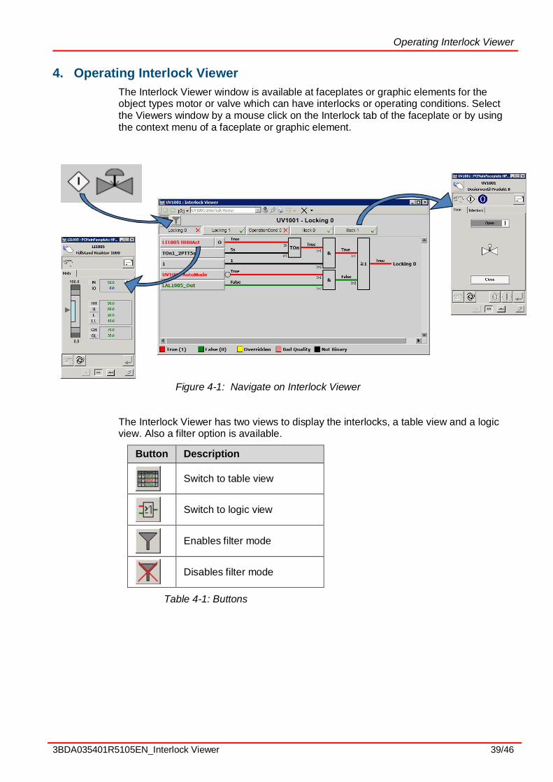
4. Operating Interlock ViewerThe Interlock Viewer window is available at faceplates or graphic elements for theobject types motor or valve which can have interlocks or operating conditions. Selectthe Viewers window by a mouse click on the Interlock tab of the faceplate or by usingthe context menu of a faceplate or graphic element.
Figure 4-1: Navigate on Interlock Viewer
The Interlock Viewer has two views to display the interlocks, a table view and a logicview. Also a filter option is available.
Button Description
Switch to table view
Switch to logic view
Enables filter mode
Disables filter mode
Table 4-1: Buttons

Operating Interlock Viewer
3BDA035401R5105EN_Interlock Viewer 40/46
Figure 4-2: Table view
Figure 4-3: Logic view
Navigate to signal source
By left click of an input in the table or logic view, the default aspect (normally thefaceplate) of the input’s object (if any) will open. On right click the context menu of theinput’s object (if any) is shown up.
If the source is not a reference to an 800xA object output, the object name iscalculated by the name of the variable.
The name of the variable will be cut at the last underscore character and the InterlockUploader checks, if an object exists with this name in 800xA. This will run until an

Operating Interlock Viewer
3BDA035401R5105EN_Interlock Viewer 41/46
object is found or no more underscore available.Example (see picture below): For the variable “LI1005_GTHHH_Out” the source objectis LI1005 (an object named “LI1005_GTHHH” doesn’t exist for this exampleconfiguration).
Figure 4-4: Navigation example
Filter settings
By activating the filter, the displayed entries are filtered by the signal state. In the tableview the entries with “Good” state are hidden. In the logic view the variables andmodules with good state are displayed in gray.
The calculation of the “Good” and “Bad” states is done only by the variablevalue (True or False). There is no consideration to the type of the module andthe module algorithm.
All modules and variables connected to a module are hidden, if the output of themodule has the good state (consider the inverting at the next module).
Figure 4-5: Table view in filter mode

Operating Interlock Viewer
3BDA035401R5105EN_Interlock Viewer 42/46
Figure 4-6: Logic view in filter mode
Loop indication
Loops in control logic are indicated by a letter surrounded by a circle. The loop sourceis located at the output of a module (below the connection line) and the loop target isshow as input of the module (instead of a variable) where the loop destination isconnected.
Figure 4-7: Logic view with loop (indicated as “A”)

Operating Interlock Viewer
3BDA035401R5105EN_Interlock Viewer 43/46
Indication of additional data type components
If additional components of structured data type are defined and currently active, thevalue indication in the logic and table view are extended by additional text andbackground color.
The additional components are indicated as a letter after the value, if they are active. Ifmore the one additional component is active, all states are shown separated with acomma.
The value field is filled with a background color. If more than one additional componentis active the color is selected in the same order as in the table below
Component Letter Color (see color definition)
Reset enabled R PCIVResetEnabled
Alarm disabled D PCIVAEDisabled
Jog J PCIVJog
Out of Service OOS PCIVOutOfService
Forced F PCIVForced
Manual M PCIVManual
Bad status B PCIVBadStatus
Table 4-2: Additional data type component identification
Figure 4-8: Logic view with alarm disabled and forced input values

Operating Interlock Viewer
3BDA035401R5105EN_Interlock Viewer 44/46
Figure 4-9: Table view with alarm disabled and forced input values
The letter and color meaning (legend) can display by click on the up arrow button onthe lower right edge of the legend area. To hide the additional legend info click thisbutton again.
Figure 4-10: Legend of the additional components
Override Interlock conditions
In some cases it might be necessary to override certain interlocks. To block or releasean interlock, a function block called BlockIL or ReleaseIL must be placed in the functiondiagram, were the interlock should be blocked or released. These function blocks areprovided within the PC_Lib and similar function blocks are also part of the chemicalextension for OGP REUSE Solutions Lib.
The BlockIL and ReleaseIL function blocks are not shown in the PC Interlock Viewer.Instead, the variable or module located before the BlockIL or ReleaseIL module aredisplayed with a button to switch the override on or off.
To override an interlock, the user must have the permission “Overrideinterlock”. If this permission is not granted, the override button to switch theoverride is disabled.

Operating Interlock Viewer
3BDA035401R5105EN_Interlock Viewer 45/46
Figure 4-11: Example configuration for Override functionality
Figure 4-12: Overridden signals will be display in yellow by default (see Interlock Display Colors).
If the “Show the current values as text in logic view” setting is set, the overriddenvalues are surround by ( ), to indicate an override also for color blind humans.
Figure 4-13: Overridden signals redundantly coded for color blind humans.

3BDA035401R5105EN_Interlock Viewer 46/46
3BDA035401R5105EN_Interlock Viewer Germany 2014-06-11
Copyright © 2015 by ABB. All Rights Reserved
® Registered Trademark of ABB.
™ Trademark of ABB.
BU Oil, Gas and Petrochemical
Frankfurt, Germany
www.abb.com/Chemicals