System Operation and Flow Controls -...
56
Refrigeration System Operation and Flow Controls Student Resource Package No: 9/10/29 Delivery: Competence in this training program can be achieved through either a formal education setting or in the workplace environment. Recognition of Prior Learning: The student/candidate may be granted recognition of prior learning if the evidence presented is authentic and valid which covers the content as laid out in this package. Package Purpose: This package provides the student with the underpinning knowledge in regards to the operational characteristics of refrigeration / air conditioning systems and the various associated flow controls. Suggested Resources: Australian Refrigeration and Air Conditioning Vol 1&2. Various Manufacturers Service and Installation Manuals. Assessment Strategy: The assessment of this package is holistic in nature and requires the demonstration of the knowledge and skills identified in the student package content summary. To be successful in this package the student must show evidence of achievement in accordance with the package Competence: This package should be supported by workplace exposure in regards to the operational characteristics of refrigeration / air conditioning systems and the various associated flow controls under the guidance of a licensed mentor. Completion: On completion of this package you will obtain results in the National Refrigeration Module Numbers: NR09 / NR10 & NR29. Assessment: Refrigeration Systems Operation & Flow Controls Compiled By: G Riach & R Baker Ultimo 2005 1
Transcript of System Operation and Flow Controls -...

Refrigeration System Operation and Flow Controls
Student Resource Package No: 9/10/29 Delivery: Competence in this training program can be
achieved through either a formal education setting or in the workplace environment.
Recognition of Prior Learning: The student/candidate may be granted
recognition of prior learning if the evidence presented is authentic and valid which covers the content as laid out in this package.
Package Purpose: This package provides the student with the
underpinning knowledge in regards to the operational characteristics of refrigeration / air conditioning systems and the various associated flow controls.
Suggested Resources: Australian Refrigeration and Air Conditioning
Vol 1&2. Various Manufacturers Service and Installation
Manuals. Assessment Strategy: The assessment of this package is holistic in
nature and requires the demonstration of the knowledge and skills identified in the student package content summary. To be successful in this package the student must show evidence of achievement in accordance with the package
Competence: This package should be supported by workplace
exposure in regards to the operational characteristics of refrigeration / air conditioning systems and the various associated flow controls under the guidance of a licensed mentor.
Completion: On completion of this package you will obtain
results in the National Refrigeration Module Numbers: NR09 / NR10 & NR29.
Assessment: Refrigeration Systems Operation & Flow Controls Compiled By: G Riach & R Baker Ultimo 2005
1

Grade Code: 72 GRADE CLASS MARK (%) DISTINCTION >=83 CREDIT >=70 PASS >=50 Assessment Events: 1. Theory / Practical Test Refrigeration System Operation 50% 2. Theory / Practical Test Flow Controls 50%
Total Marks: 100%
Theory Tests: Test. 1 Short answer questions, Pressure Enthalpy Charts and
Calculations. Test. 2 Short answer questions, circuit diagrams, control settings and fault
finding. These two assessments cover the contents as laid out in the student
resource package. Content Summary: Introduction to the Pressure Enthalpy (Ph) Diagram: 3
• Calculating System Capacity (PE Charts): 8
• Heat Exchangers Compressor Efficiency & Capacity Control: 13
• Sample Pressure Enthalpy Charts: 19
Refrigerant Flow Controls: 22
• Hand Expansion: 22
• Automatic Expansion Valves:
23
• Capillary Tubes and Accurators: 26
• Thermostatic Expansion Valve (TXV): 30
• High Side and Low Side Floats: 39
• Thermal Electric Expansion Valve: 41
• Electronic Evaporator Control System: 42
• EPR and CPR Valves: 44
• Reversing Valves and Solenoid Valves: 47
Refrigeration Systems Operation & Flow Controls Compiled By: G Riach & R Baker Ultimo 2005
2

Student Resource Package No: NR 9/1029
Section No: 1
Introduction to the Pressure Enthalpy (Ph) Diagram Purpose: The purpose of this section is to provide you with the underpinning knowledge and skills in obtaining information to interpret and use the pressure enthalpy chart. From the information obtained from an operating vapour compression system plot the refrigeration cycle on a pressure enthalpy chart and determine the systems capacity. Properties of a Pressure Enthalpy (Ph) Diagram (ARAC, 23.8 - 23.26) The pressure enthalpy chart can be utilised to determine the following properties:
• Enthalpy (kJ / kg): The total amount of heat in one kg of refrigeration calculated from a temperature base.
• Absolute pressure (kPa absolute).
• Constant temperature (Degrees C).
• Specific volume (m3
/ kg or L / kg) : The volume weight of refrigerant entering the suction of the compressor.
• Entropy (kJ / kg K): These lines are used to mark the path through the
compressor ie the compressor process.
• Density (kg / L): Mass per unit volume.
• Flash gas percentage:
Flash gas: is the term used to indicate that portion of refrigerant which evaporates instantly (flashes) and turns into a vapour as it passes through the refrigerant control orifice. The instant vapourising of some of the refrigerant (flash gas) cools the rest of the liquid to the evaporator temperature. The amount of flash gas depends on the temperature of the refrigerant in the liquid line and the pressure inside the evaporator.
Further information to be found on the pressure enthalpy (Ph) diagram
• Sub-cooled zone, the area of the diagram where the refrigerant has been cooled below saturation.]
Refrigeration Systems Operation & Flow Controls Compiled By: G Riach & R Baker Ultimo 2005
3

• Saturated zone, the area of the diagram where there is a change in state occurring without a change in temperature.
• Superheated zone, the area of the diagram where the refrigerant has been
heated above saturation. • Saturated liquid line, part of the curve where the refrigerant is one hundred
percent refrigerant. • Saturated vapour lines, part of the curve where the refrigerant is one hundred
percent vapour.
• Quality lines, the lines between the saturated liquid and the vapour lines. These lines are used to identify the liquid / vapour mix.
Plotting the Cycle
Fig .1. To plot a simple cycle, you will need to obtain:
• Suction and discharge absolute pressures or alternately these two pressures converted to saturated suction and condensing temperatures.
• Temperature of the refrigerant entering the compressor.
• Temperature of the liquid refrigerant entering the metering device.
Refrigeration Systems Operation & Flow Controls Compiled By: G Riach & R Baker Ultimo 2005
4

Refrigeration Effect: This is the amount of heat absorbed by the evaporator from the product kJ / kg. Refrigeration effect is found by subtracting the enthalpy at A from B RE = B - A Where: RE = Refrigeration effect. (kJ / kg) A = Enthalpy of the refrigerant entering the evaporator immediately after the metering device. (kJ / kg). B = Enthalpy of the refrigerant at the point where it enters the suction of the compressor. (kJ / kg). Heat of Compression: This is the heat gained from the compression cycle. It is found by subtracting the enthalpy at C from D H of C = D – C Where: H of C = Heat of Compression (kJ / kg) C = Enthalpy of the refrigerant at the point where it enters the suction line of the compressor. (kJ / kg). D = Enthalpy of the refrigerant at the point where it discharges from the compressor. (kJ / kg). Heat of Rejection: The heat of rejection is the total heat rejected by the condenser. This includes the heat gained through the refrigeration effect, suction line and heat of compression. It is found by subtracting the enthalpy at A from D. H of R = D – A Where: H of R = Heat of Rejection (kJ / kg) A = Enthalpy of the refrigerant entering the evaporator immediately after the metering device (kJ / kg) D = Enthalpy of the refrigerant at the point where it discharges from the compressor. (kJ / kg).
Refrigeration Systems Operation & Flow Controls Compiled By: G Riach & R Baker Ultimo 2005
5

Refrigeration Systems Operation & Flow Controls Compiled By: G Riach & R Baker Ultimo 2005
6
A way of checking your figures is to use the following calculation: H of R = RE + H of C The small difference between the two is the amount of heat picked up in the suction line (B to C). Specific Volume Entering the Compressor: This value is taken straight from the PE chart as shown in Fig .1. Mass Flow Rate This is the amount of refrigerant (kg) which is circulated in a refrigeration system per second. The mass flow rate is determined by: Compressor Displacement (L / S) Mass flow rate = Specific Volume Entering Compressor (L / kg) For example: A package air conditioning system operates under the following conditions:
• Refrigerant R22 • Average room temperature 22°C • Discharge pressure 1750 kPa gauge • Suction pressure 464 kPa gauge • Refrigerant temperature entering the compressor 12°C • Refrigerant temperature entering the metering device 26°C
From the above details plot the refrigeration cycle on a PE chart (on page7) and determine the following:
• Refrigeration effect • Heat of compression • Heat of rejection • Specific volume entering the compressor • Percentage of flash gas.
Coefficient of Performance: The coefficient of performance (C.O.P.) of a refrigerating cycle is an expression of the cycle efficiency and is stated as the ration of heat absorbed in the refrigerated space to the heat energy equivalent of the energy supplied to the compressor. C.O.P. = Refrigerating Effect KJ/ kg Example: If: RE = 170 KJ/kg Heat of Compression KJ/kg H of C = 35 C.O.P. = 170 = 4.85 35 This means that for every 1kW input to the unit we will get 4.85 kW of refrigerating effect. If we require the unit to heat, then we are also expending the heat of compression into the conditioned area which will further increase our C.O.P.
Note: If using pressure readings to plot the cycle remember to convert to absolute pressure. (Add 101 kPa to your gauge pressure).

stems Operation & Flow Controls Compiled By: G Riach & R Baker Ultimo 2005 7
Refrigeration Sy
Calculating System Capacity (PE Charts)
Section No: 2 Purpose: The purpose of this section is to provide you with the underpinning knowledge and skills to enable you to determine the capacity of a refrigeration system by utilising the pressure enthalpy chart and its processes. There are many reasons why the system’s capacity is required to be calculated these include:
• Testing actual capacity against rated capacity.
• Engineers are required to calculate a systems capacity to ensure correct size equipment for the job.
• When retrofitting a system to ensure the correct capacity of the system after
the refrigerant has been changed.
• As a fault finding tool Steps required to calculate a systems capacity are as follows:
1. Plot the cycle on a PE Chart (use the previous example on page, 7)
2. Calculate the compression ratio, using the following formula:
Compression Ratio = Absolute Discharge Pressure Absolute Suction Pressure This answer as : 1
3. The volumetric efficiency: the volume of vapour the compressor pumps is always less than 100% volume. This is known as volumetric efficiency.
There are five main factors which affect reciprocating compressors efficiency:
• Efficiency of compressor valves. • Piston fit. • Clearance between the piston at top dead centre and the valve plate. • Vapour entering a hot cylinder • Compression ratio.
Refrigeration Systems Operation & Flow Controls Compiled By: G Riach & R Baker Ultimo 2005
8

Note: volumetric efficiency table attached Volumetric Efficiency%
100%
80%
60%
VE
40%
20%
0% 2 4 6 8 10 12 14 16 18 20 Compression Ratio
4. The compressor speed, this can be calculated using the following formula: d1 n1 = d2 n2 Where: d1 = diameter of compressor pulley (mm or m) d2 = diameter of motor pulley (mm or m) n1 = speed of compressor (rpm) n2 = speed of motor (rpm). 5. Compressor displacement, compressor displacement (swept volume if
compressor is 100% efficient) using the following formula:
Dg = B2 x S x N x n x 13.1 Where: Dg = Theoretical displacement (L / s) B = Bore diameter of the cylinder in metres. S = Stroke length of the compressor in metres. N = Number of cylinders. n = Speed of the compressor (rpm). 13.1 = Constant value.
6. Actual compressor displacement, multiply the compressor displacement by its volumetric efficiency in % Formula = Dg = Dg x nv Where: Dg = Theoretical displacement of compressor nv = Volumetric efficiency (%) – as attained in step 3.
Compressor Displacement (L / S)
Refrigeration Systems Operation & Flow Controls Compiled By: G Riach & R Baker Ultimo 2005
9

7. Mass flow rate = Specific Volume Entering Compressor (L / kg 8. Capacity = Mass flow rate x Refrigeration effect Q = M x RE. 9. Most of the manufacturers list the compressor displacement in m3/hr and to
convert to L/s the following applies: Example: Convert 12 m3 / hr to L/s
• 1000 L to 1m3 • 3600 seconds per hour.
L/s = 12 x 1000 = 3.33 L/s 3600
Practical Exercise
Refrigeration Systems Operation & Flow Controls Compiled By: G Riach & R Baker Ultimo 2005
10

Pressure Enthalpy Aim: To determine the operating refrigeration capacity of the low the temperature freezer cabinet in the refrigeration workshop. (Refrigerant R404A). Procedure:
• Fit a set of service gauges to the system, turn the main switch on and allow cabinet to come down to at least -15°C.
• Obtain suction and discharge pressures.
• Using digital thermometers determine the required temperature readings.
• Plot the refrigeration cycle on a pressure enthalpy chart and determine the
following:
1. Refrigeration effect 2. Heat of compression 3. Total heat rejection 4. Percentage of flash gas 5. Specific volume of refrigerant entering the compressor 6. Heat of compression. 7. Displacement of compressor equals: 14.5m3/hr. 8. Mass flow rate 9. Capacity.
Note show all calculations and working in the space provided below:
1. Refrigeration effect:
2. Heat of compression:
3. Total heat of rejection:
Refrigeration Systems Operation & Flow Controls Compiled By: G Riach & R Baker Ultimo 2005
11

4 Percentage of flash gas:
5. Specific Volume Entering Compressor:
6. Compression ratio:
7. Displacement of compressor (Actual):
8 Mass flow rate:
9 Capacity:
Heat Exchangers / Suction Line Accumulators / Compressor Efficiency & Capacity Control
Refrigeration Systems Operation & Flow Controls Compiled By: G Riach & R Baker Ultimo 2005
12

Section No: 3
Purpose: The purpose of this section is to provide you with the underpinning knowledge and skills to carry refrigeration system efficiency testing and the various methods of capacity control. Heat exchangers: Heat exchangers are used in the HVAC & refrigeration industry to ensure that the liquid refrigerant entering the metering device is sub-cooled. The major benefit of adding a heat exchanger to the system is that the evaporator can remove a larger amount of heat. (ARAC, 6.14 & 18.18).
Suction line
Liquid line in
Liquid line out
Suction line heat exchanger
The addition of a heat exchanger reduces flash gas and increases the evaporator surface area.
Suction line heat exchanger: This type of heat exchanger transfers heat between the suction and liquid lines. Suction line heat exchangers:
• Assist in the prevention of liquid flood back
• Increases the suction vapour temperature to prevent condensation or frosting on the suction line.
• Lowers the evaporator flash gas by sub-cooling the liquid refrigerant entering
the evaporator and increases coil capacity.
Suction Line Accumulator:
Refrigeration Systems Operation & Flow Controls Compiled By: G Riach & R Baker Ultimo 2005
13

The suction line accumulator is installed in a system to protect the compressor from damage due to slugs of liquid refrigerant. Reverse cycle units and system with hot gas defrost may require a suction line accumulator. The suction line accumulator is designed to collect liquid refrigerant before it reachers the compressor and it should be located as close to the compressor as possible. However when a reversing valve is used in a system the accumulator must be fitted between the reversing valve and compressor.
Liquid level
From evaporator
Vapour
To compressor
Compressor Efficiency: One of the most common problems with compressors is inefficient valves or a damaged valve plate. If either the discharge or suction valves leak the compressor efficiency drops. There are many reasons why valves may leak refrigerant and these range from a small scratch across the seat of the valve plate to a valve being damaged from the compressor pumping liquid refrigerant. Testing compressor valves: Suction valves:
• “Install service gauge manifold” • Front seat suction service valve • Turn on compressor and allow to operate • Record the best vacuum obtainable against its normal discharge head
pressure and record the time taken. • The compressor should be able to pull a vacuum between – 50 to – 60 kPa:
anything less than this would require an overhaul or replacement. Discharge valves:
Refrigeration Systems Operation & Flow Controls Compiled By: G Riach & R Baker Ultimo 2005
14

• High head pressure will leak back through the discharge valve and produce a pressure above atmospheric on the compound gauge.
• Forward seat the discharge service valve the as indicated on the high pressure gauge will decrease
Methods of Capacity Control: (ARAC, 7.23) The following indicates capacity control methods for various compressors, evaporators and condensers: Compressors:
• Scroll compressors: capacity is controlled by varying the speed of the compressor.
• Rotary compressors: Same as the scroll by varying the compressor
speed.
• Screw compressors: capacity is controlled by varying the amount of discharge vapour leaving the compressor.
• Centrifugal compressors: capacity is controlled by adjusting the inlet
guide vanes on the suction vapour entering compressor.
Evaporators: The following methods are used to control the capacity of evaporators:
• Capacity control of the product load.
• Capacity control of a cooling medium ie: chilled water. Air cooled evaporators: Capacity control of air cooled evaporators can be achieved by either face dampers or face and bypass dampers.
• Face Dampers: the capacity of the evaporator is achieved by dampers that are fitted across the face of the evaporator to vary the air flow.
• Face and bypass Dampers: the capacity is varied by when the face dampers
close down the air is bypassed through a second set of dampers.
Water cooled evaporator:
Refrigeration Systems Operation & Flow Controls Compiled By: G Riach & R Baker Ultimo 2005
15

The capacity control of a water cooled evaporator is achieved by a three way modulating valve. Condenser capacity control: To maintain a constant head pressure regardless of the ambient temperature the following capacity control methods can be utilised: Air cooled condensers:
• Dampers fitted in the air on stream controlled either by a thermostat or high pressure control.
• By cycling the condenser fans or fan on and off by either a thermostat or high
pressure control.
• Varying the speed of the condenser fan motor using electronic speed controllers (solid state).
Water cooled condensers:
• Installing a three way bypass modulating water valve.
• A water regulating valve that opens and closes according to the head pressure. Cooling tower capacity: To maintain constant head pressure in an air conditioning system which incorporates a cooling tower the water temperature should be around 35ºC entering and leaving around 29°C. To maintain these temperatures the following methods apply:
• Three way by-pass modulating water valve.
• Control the fan speed by using a variable control method.
• Cycling the fan motor on a thermostat. Evaporative condenser capacity control: To control the capacity of an evaporative condenser the following methods may be utilised:
• Regulating the air across the condenser coils either by using variable fan speed control or damper blades controlled by a thermostat or high pressure control.
Review Questions Section No: 1, 2 & 3
Refrigeration Systems Operation & Flow Controls Compiled By: G Riach & R Baker Ultimo 2005
16
Q.1 List five properties that can be determined with the aid of a pressure enthalpy
diagram:
Q.2 What data is required to plot a simple refrigeration cycle on a pressure
enthalpy?
Q.3 Describe what is the main purpose of a refrigerant heat exchanger:
Q.4 What is the advantage of sub-cooling liquid refrigerant in the liquid line?
Q.5 State the method capacity control on a centrifugal compressor:
Q.6 Give one example of capacity control on both aircooled and chilled water
evaporators:
Q.7 State two methods of capacity control on a cooling tower:
Q.8 Describe in your own words the purpose of the suction line accumulator:
Refrigeration Systems Operation & Flow Controls Compiled By: G Riach & R Baker Ultimo 2005
17

Refrigeration Systems Operation & Flow Controls Compiled By: G Riach & R Baker Ultimo 2005
18
Q.9 State the temperatures that you would expect the entering and leaving water of
a cooling tower to be:
Q.10 Describe the method and operation of capacity control on a centrifugal
compressor:
Refrigeration Systems Operation & Flow Controls Compiled By: G Riach & R Baker Ultimo 2005
19

100 150 200 250 300 350 400 450 500 550 600
0,3
100 150 200 250 300 350 400 450 500 550 600
0,40,50,60,81
1,52
3456810
1520
3040506060
504030
2015
1086543
21,5
10,80,60,50,40,3
d(25°C) :1,041Tc :72°CPc :37,4Tbulle :-45,8
s=1kJ/ kg.Kh=200kJ/kgT=0°CREFERENCES
v : m³ /kgs : kJ/kg.Kh : kJ/kg
T : °CP : barUNITES
1,74
2,12,08
2,062,042,0221,981,961,941,921,9
1,881,86
1,841,82
1,81,78
1,761,721,681,641,6
0,30,250,20,1750,150,1250,10,08
0,060,050,040,0350,03
0,0250,020,0175
0,0150,0125
0,010,008
0,90,80,70,60,50,40,30,20,1 120100806040200-20-40
60
50
40
3020
10
0
-10
-20
-30
-40
-50
FORANE 404A (FX70)
Refrigeration Systems Operation & Flow Controls Compiled By: G Riach & R Baker Ultimo 2005
20

100 150 200 250 300 350 400 450 500 550 600
0,30,40,50,60,81
1,52
3456810
15
100 150 200 250 300 350 400 450 500 550 600
20
30405060
0,30,40,50,60,81
1,52
3456810
1520
30405060
UNITES P : bar T : °C
h : kJ/kg s : kJ/kg.K v : m³ /kg
REFERENCES T=0°C h=200kJ/kg s=1kJ/ kg.K
T eb : -26,4 Pc : 40,7 Tc : 101 d(25°C) : 1,210
2,14
2,12
2,12,08
2,062,042,022
1,981,96
1,941,92
1,91,88
1,861,841,81,761,721,68
0,30,250,20,1750,150,1250,10,08
0,060,050,040,0350,030,025
0,020,0175
0,0150,0125
0,010,008
0,0060,005
0,90,80,70,60,50,40,30,20,1 140120100806040200-20
9080
70
60
50
40
30
20
10
0
-10
-20
-30
FORANE 134a
Refrigeration Systems Operation & Flow Controls Compiled By: G Riach & R Baker Ultimo 2005
21

Refrigerant Flow controls: Section No: 4
Purpose: The purpose of this section is to provide you with the underpinning knowledge and skills to identify the various flow controls and in particular the operation of the automatic and hand expansion valves. Refrigeration and air conditioning systems require some form of metering control to:
• Reduce the high-pressure sub-cooled liquid to a low-pressure saturated liquid.
• Control the flow rate of refrigerant into the evaporator to match the evaporation rate
• Ensure maximum capacity without starving or flooding the evaporator.
- Starving reduces the evaporator capacity - Flood back can lead to compressor damage.
Types of Flow Controls: (ARAC, 5.1 – 5.28). The following flow controls are used in various refrigeration and air conditioning systems:
• Hand Expansion Valve • Automatic Expansion Valve • Capillary Tube • Accurator • Thermostatic Expansion Valve (TXV) • Thermoelectric Expansion Valve • High Side Float • Low Side Float • Electronic Evaporator Control Systems. • Evaporator Pressure Regulating Valve (EPRV) • Crankcase Pressure Regulating Valve (CPRV) • Solenoid Valves • Reversing Valves.
Hand Expansion Valve: (ARAC 5.2 Volume 1.) The simplest feeding refrigerant consists of a valve body fitted with a tapered spindle. This valve is manually operated and requires a plant operator to adjust the valve to feed a fixed quantity of refrigerant to balance the evaporator to refrigerant load. Note: Figure 1 Hand Expansion Valve Application: Used on large industrial refrigeration system as an emergency metering
device should the main automatic metering device fail or requires servicing.
Refrigeration Systems Operation & Flow Controls Compiled By: G Riach & R Baker Ultimo 2005
22

Advantages:
• Cheap • Trouble free • Performs adequately in the correct application.
Disadvantages:
• Must be manually opened and shut each time the compressor cycles on an off and must be adjusted as the load varies.
• Cannot be used on applications where the load frequently varies.
Fig. 1 Hand Expansion Valve
Automatic Expansion Valve: The automatic expansion valve maintains a constant pressure in the evaporator by flooding more or less of the evaporator in response to changes in the evaporator load. The constant pressure of the valve results from the interaction of two opposing forces: (P1) Evaporator Pressure (P2) Spring Pressure.
• Evaporator pressure exerted on one side of the bellows acts as to close the valve
• Spring pressure is exerted on the other side of the bellows acts to open the valve
Operation:
Refrigeration Systems Operation & Flow Controls Compiled By: G Riach & R Baker Ultimo 2005
23

While the compressor operates, the valve functions to maintain the evaporator and spring pressure in equilibrium. Once the spring tension is adjusted for the desired evaporator pressure the valve will automatically regulate the flow of refrigeration into the evaporator so that the desired evaporator pressure is maintained regardless of the evaporator load Note: These valves require a critical refrigerant charge. Application: These valves were mainly used in small retail ice cream cabinets and are seldom used these days because of their inability to adjust to varying evaporator loads. Disadvantages:
• Poor efficiency when compared to other types of metering devices. • Evaporator load must be kept relatively constant. • When evaporator load increases the valve tends to close. • When the evaporator load decreases the valve tends to open.
Fig. 2 Automatic Expansion Valve
Refrigeration Systems Operation & Flow Controls Compiled By: G Riach & R Baker Ultimo 2005
24

Review Questions Section No: 4 Q.1 What are the three main requirements of a refrigerant metering device?
Q.2 Where in the refrigeration industry are hand expansion valves used?
Q.3 List the advantages of a hand expansion valve:
Q.4 What are the disadvantages of a hand expansion valve?
Q.5 The two main forces exerted on an automatic expansion valve are:
Q.6 What type of refrigerant charge does a automatic expansion valve require?
Q.7 List at least three disadvantages of an automatic expansion valve:
Refrigeration Systems Operation & Flow Controls Compiled By: G Riach & R Baker Ultimo 2005
25

Capillary Tubes & Accurators
Section No: 5
Purpose: The purpose of this section is to provide you with the underpinning knowledge and skills in the operation and applications for both the capillary tube and accurator Capillary Tube: The simplest of all refrigerant flow controls is the capillary it is simply a fixed length of small diameter tubing installed between the condenser and evaporator. It usually replaces the liquid line. Operation: The capillary acts to restrict or meter the flow of liquid from the condenser to the evaporator. The high frictional resistance to the liquid flowing through it, which is the result of its length and small bore maintains the required operating pressure differential between the high and low sides of the system. Applications: Capillary tubes are commonly used:
• Domestic refrigerators / freezers. • Residential air conditioning systems. • Small commercial package air conditioning / refrigeration systems.
Advantages: • Relatively trouble free operation (no moving parts). • No receiver (smaller refrigerant charge) • Low starting torque compressor motor (refrigerant equalises on the off cycle).
Disadvantages:
• Requires a critical refrigerant charge. • Easy to block with silver solder during installation and service. • Does not modulate as the load changes.
Fig. 1 Capillary Tube
Refrigeration Systems Operation & Flow Controls Compiled By: G Riach & R Baker Ultimo 2005
26

Accurator: The accurator (or two way flow control) is a metering device that controls the refrigerant flow rate into the evaporator due to a pressure drop caused by the internal resistance of a small hole in the orifice plate.
Operation: The accurator consists of a brass housing which contains a fixed sized moving orifice. The orifice acts to restrict the flow of refrigerant and maintains a pressure differential between the condenser and evaporator. Refer Fig. 2. Liquid refrigerant enters the outer casing and forces the orifice plate into a seat that seals the outer edge of the plate eliminating by pass flow. Liquid refrigerant is forced through the small orifice, which causes a pressure drop. The valve body and orifice unseats and allows free flow of refrigerant around it when the flow is reversed. When in this position the accurator offers no restriction to flow. Applications:
• Residential air conditioning systems. Advantage:
• Single moving part • No liquid receiver.
Disadvantage:
• The accurator must be installed in the correct refrigerant flow direction. • Critical refrigerant charge.
Refrigeration Systems Operation & Flow Controls Compiled By: G Riach & R Baker Ultimo 2005
27

Review Questions Section No: 5
Q.1 List three applications for a capillary tube:
Q.2 State two advantages of a capillary tube:
Q.3 What are the two main disadvantages of a capillary tube?
Q.4 Describe the operation of a capillary tube:
Q.5 Describe the operation of an accurator:
Q.6 State two advantages and two disadvantages of an accurator:
Q.7 Where are accurators commonly used?
Thermostatic Expansion Valve (TXV)
Refrigeration Systems Operation & Flow Controls Compiled By: G Riach & R Baker Ultimo 2005
28

Section No: 6
Purpose: The purpose of this section is to provide you with the underpinning knowledge and skills in regards to operational characteristics of both the internal and external thermostatic expansion valves. This section will also cover superheat adjustment of TX valves and various refrigerant distributors. Thermostatic Expansion Valve (TXV) ARAC pages, 5.10, 24.11 Thermostatic expansion valves are the most common metering devices used in refrigeration and air conditioning systems. Thermostatic expansion valves maintain a constant superheat at the outlet of a dry expansion evaporator to ensure the maximum surface area of the evaporator is wet with liquid refrigerant under all conditions.
Power element Liquid line inlet Outlet (evaporator)
Sensing bulb
Superheat adjustment
TX valve bulb clamped firmly to the suction line around 4pm.
Operation: The TX valve has a remote bulb that is clamped firmly to the suction line at the evaporator outlet around 4pm note above; the bulb is filled with a saturated liquid vapour mixture. As the evaporator load increases the liquid vapour in the bulb expands forcing the valve to open. There are three forces, which govern the thermostatic expansion valve’s operation. These forces are as follows:
Refrigeration Systems Operation & Flow Controls Compiled By: G Riach & R Baker Ultimo 2005
29

1. Pressure (P1) created by the remote bulb and governed by the temperature of
the superheated refrigerant leaving the evaporator. Opening Pressure
2. Evaporator pressure (P2). Closing Pressure.
3. Superheat adjustment spring (P3). Closing Pressure
P1 = P2 + P3 If the valve does not feed enough refrigerant, the evaporator pressure drops and the bulb pressure is increased by the warmer vapour leaving the evaporator and then the valve opens until the three pressures are balanced. Superheat It is often necessary to measure the TX valves superheat to ensure that the evaporator has sufficient liquid refrigerant for maximum evaporator surface area. By obtaining the correct manufacturers superheat specifications (usually around 5K) maximum refrigeration capacity can be achieved. Superheat adjustments enable the evaporator to be flooded with saturated liquid refrigerant and thus not starving the evaporator and or flooding liquid back to the compressor. TX valve superheat adjustment Refrigeration System Operating On R134a
SET = -4°C
2° C
Gauge pressure
151 kPa TX Valve Superheat Adjustment
1. Determine the actual temperature at the TX Valve sensing bulb 2. With a set of service gauges determine the saturated temperature of refrigerant
leaving the evaporator 3. Superheat is found by deducting step 2 from step 1 4. On long suction lines 1 K should be factored in due to suction line pressure
drop. Example:
Refrigeration Systems Operation & Flow Controls Compiled By: G Riach & R Baker Ultimo 2005
30

• Refrigeration system above operates on R134a • Temperature measured at the TX valve sensing bulb is 2 degrees C • Saturated evaporator pressure of 151kPa, which equals – 4degrees C. • The temperature difference between – 4 and 2 equals 6K superheat.
Hunting Hunting occurs when the TX Valve opens and closes erratically. Hunting reduces the evaporator performance and increases running costs. Hunting is usually a direct result of an oversized TX Valve or orifice. Advantages
• Evaporator is fully flooded under all load conditions. • Maintains control over a wide operating temperature range. • Evaporator refrigerant velocity is maintained under all load conditions to
minimise oil logging. Disadvantages
• Evaporator temperature/pressure is not constant. TX Valve Bulb Charges Thermostatic expansion valves may contain one of the following charges in their power element: Liquid Charged This type of power assembly has the same refrigerant as in the system and ensures that liquid is in the bulb under all temperature conditions. Note: this type of power assembly tends to open wide under heavy loads and possible liquid floodback, usually recommended for large capacity ammonia systems. Gas Charged This type of power assembly has the same refrigerant as in the system or a fluid with the same pressure/temperature relationship and is mainly used on air conditioning applications providing constant superheat settings in the mid-range. It also has poor control at the top and bottom of its range. They can also be set up as a maximum operating pressure (MOP) for compressor overload protection. Cross Charged This type of power assembly can be also set up as a MOP for compressor overload protection. The power assembly has a different refrigerant to that of the system and a different pressure/temperature curve across the evaporator temperature range and therefore providing better superheat control. TX Valve Selection To select the correct TX Valve and its capacity for individual applications the following factors must be considered:
• Refrigerant type
Refrigeration Systems Operation & Flow Controls Compiled By: G Riach & R Baker Ultimo 2005
31

• System application • Evaporator design capacity • Td of evaporator • Amount of sub-cooling available in the liquid line (inlet to TXV) • Pressure drop across TX Valve • Refrigerant distributor if fitted.
Internally Equalised TX Valves The internally equalised TX Valve is used on evaporators that have a single circuit with a low pressure drop (under 21 kPa). Refer attached circuit diagram. Externally Equalised TX Valves
Internal Equalised TX Valve
Externally equalised TX Valves are used when excessive pressure drop exists within the evaporator. These valves are fitted with an external pressure connection on the valve body and have a refrigerant line connected to the end of the evaporator next to the sensing bulb and transmit pressure to the underside of the power assembly. This averages the pressure drop across the evaporator providing good control of the valves operation. Refer attached circuit diagram.
External Equalised TX Valve
Distributors Purpose: If a large capacity evaporator was designed as a single series circuit there would be a high pressure drop created as the evaporator circuit would be so long.
Refrigeration Systems Operation & Flow Controls Compiled By: G Riach & R Baker Ultimo 2005
32

To overcome this multi-circuit evaporators are used to reduce pressure drop. Refrigerant distributors are fitted to ensure equal refrigerant feed to each of the circuits as indicated in the drawing below:
Multi-circuit evaporator
Refrigerant distributor
Distributors supply equal quantities of the refrigerant liquid / vapour that has been thoroughly mixed to each circuit of a multi-circuited evaporator. There are four main types of refrigerant distributors and they are as follows:
• Centrifugal • Pressure Drop • Manifold • Venturi.
Centrifugal: This type has a high entrance velocity to the distributor which creates a swirling effect and maintains an excellent mixture of liquid and flash gas. The refrigerant is then evenly distributed to evaporator circuits.
Pressure Drop: The pressure drop type consists of a housing in which the outlet end is drilled to connect tubes from the distributor to the evaporator. The inlet of the distributor is recessed as nozzles can be changed.
Refrigeration Systems Operation & Flow Controls Compiled By: G Riach & R Baker Ultimo 2005
33

The refrigerant enters the inlet of the distributor and passes through the nozzle which is sized to produce a pressure drop. This causes the liquid velocity to increase which results in a uniform mixing of liquid / vapour.
Manifold: Manifold distributors depend on level mounting and a low entrance velocity to give an even distribution of the refrigerant to the evaporator circuits. A baffle is sometimes fitted in the header to minimise a tendency to overfeed evaporator circuits which are directly in front of the header connection. An elbow can be installed between the expansion device and header inlet to reduce the refrigerant velocity and ensure equal distribution of refrigerant to evaporator circuits.
Venturi: This utilises the venturi principle of pressure recovery. This depends on the contour for the equal distribution of the liquid / vapour refrigerant mixture to each of the
Refrigeration Systems Operation & Flow Controls Compiled By: G Riach & R Baker Ultimo 2005
34

evaporator circuits. It may be mounted in any position and provides a minimum turbulence and pressure loss.
Review Questions Section No: 6
Refrigeration Systems Operation & Flow Controls Compiled By: G Riach & R Baker Ultimo 2005
35

Q.1 List and describe the three forces which govern the operation of a thermostatic
expansion valve:
Q.2 Describe the effects on the evaporator if a TX valve is adjusted with a high
superheat setting:
Q.3 When and why would you use an externally operated TX valve:
Q.4 List three advantages of a TX valve:
Q.5 What are the three TX valve power assembly charges :
Q.6 To select the correct TX valve list five factors that must be considered:
Q.7 Describe how you would adjust the superheat setting of a TX valve:
Refrigeration Systems Operation & Flow Controls Compiled By: G Riach & R Baker Ultimo 2005
36

Q.8 What the purpose of a refrigerant distributor: ?
Q.9 List four types of refrigerant distributors:
Q.10 Where is the distributor located in a refrigeration system:?
High Side, Low Side Floats, Thermal Electric Expansion Valve
Refrigeration Systems Operation & Flow Controls Compiled By: G Riach & R Baker Ultimo 2005
37

& Electronic Evaporator System
Section No: 7
Purpose: The purpose of this section is to provide you with the underpinning knowledge and skills in regards to operational characteristics of both the high and low side floats. This section will also cover operation of thermal electric expansion valve and the electronic evaporator system. High Side Float The high side float is a liquid actuated refrigerant flow control, which regulates the flow of refrigerant to the evaporator relative to the rate at which the liquid in the evaporator is being vaporised. (ARAC, 5.3 – 5.6) The float mechanism is located in the liquid line and maintains a constant liquid level in the evaporator.
Evaporator
High side float
Condenser
Applications:
• Used as a metering device on flooded or dry expansion systems and is suitable for single evaporator only. (Centrifugal Air Conditioning equipment)
• As an oil separator on flooded evaporators (example beverage cooling
system). Oil Separator:
Refrigeration Systems Operation & Flow Controls Compiled By: G Riach & R Baker Ultimo 2005
38

Oil is collected an drops to the bottom of the oil trap until the level allows the ball float to open (on rise) and the high pressure refrigerant forces the collected oil back into the compressor sump.
Low Side Float
Evaporator regulating valve maintains a constant evaporator pressure temperature and opens on an increase in evaporator pressure.
Fig. 1
Needle and seat
Suction line Liquid line
Liquid refrigerant level Float ball Product coils
Operation: The low side float valve is a liquid level operated control that feeds a flow of liquid refrigerant to the evaporator the valve is operated by a float ball that opens on a fall in the evaporator liquid level. The level is maintained to the rate at which the refrigerant vapour is drawn from the evaporator by the compressor. Instantaneous beverage coolers use a float that operates a replacement needle and seat assembly as indicated above in Fig.1 to inject liquid refrigerant into the evaporator. When the liquid level rises the float lifts up and causes the needle and seat to shut off the flow of liquid refrigerant. Advantages:
Refrigeration Systems Operation & Flow Controls Compiled By: G Riach & R Baker Ultimo 2005
39

• Higher rate of heat transfer than the dry expansion type because the product is emersed within the liquid refrigerant.
• Can be used on a multiple evaporator system. Disadvantages:
• Much more refrigerant is required in comparison to a dry expansion evaporator
• Flooded evaporators take a long time to be defrosted. Thermal Electric Expansion Valve (ARAC, 5.19) These valves have only two separate operating parts:
• A heater and bi-metal strip • A spring loaded orifice needle.
Liquid line
Transformer
240 volt supply 24 Volts
End of evaporator suction line.
Thermistor
Power assembly
Refrigeration Systems Operation & Flow Controls Compiled By: G Riach & R Baker Ultimo 2005
40

Electronic Evaporator Control Systems (ARAC, 5.20) This evaporator control system and expansion valve is a liquid regulator for general purposes. It designed to maintain the optimum degree of super heat at the outlet of a dry expansion evaporator so under all load conditions the most economical performance is obtained. This type of control system is used extensively in the supermarket industry.
Electronically Operated Expansion Valve
Advantages:
• Minimises oil logging under all load conditions by maintaining evaporator refrigerant velocity.
• Evaporator is fully flooded under all load conditions.
• Control is maintained over a wide operating temperature range.
Disadvantages:
• These valves are difficult to set up and adjust as their operation is sometimes specific to each manufacturer.
Refrigeration Systems Operation & Flow Controls Compiled By: G Riach & R Baker Ultimo 2005
41
Review Questions Section No: 7
Q.1 On what type of system must an oil separator be used and describe its
operation:
Q.2 Give one example where a high side float is used as a metering device:
Q.3 List two advantages and disadvantages of a low side float:
Q.4 Describe the operation of a low side float:
Q.5 List the two operating parts of a thermal expansion valve:
Q.6 Give three advantages and the major disadvantage of an electronic evaporator
control valve:
Refrigeration Systems Operation & Flow Controls Compiled By: G Riach & R Baker Ultimo 2005
42

Evaporator and Crankcase Pressure Regulating Valves
Section No: 8
Purpose: The purpose of this section is to provide you with the underpinning knowledge and skills in the operational characteristics and adjustment of both the evaporator and crankcase pressure regulating valves. Evaporator Pressure Regulating Valve (EPRV) (ARAC, 6.6 – 6.8).
The evaporator pressure regulating valve (EPRV) is mainly used on multiple evaporator systems where various evaporator temperatures are required. They are set to maintain a pre-determined minimum evaporator pressure.
Applications:
• Where multiple evaporators are connected to a single condensing unit and maintain different temperatures, each of the higher temperature evaporator must have an EPR valve.
• On all instantaneous beverage coolers. Where evaporator pressure or
temperature must be maintained above a certain minimum.
• In air cooling applications where humidity must be maintained.
Typical EPR valve Installation
Evaporator
Evaporator pressure regulating valve installed in the suction line as close to the evaporator as possible.
Adjustment:
1. Connect a compound gauge to the EPRV connection. 2. Fit another compound service gauge to the suction service valve. 3. Using a screwdriver or Allen key open the valve slightly of its seat.
Refrigeration Systems Operation & Flow Controls Compiled By: G Riach & R Baker Ultimo 2005
43

4. Compressor gauge should indicate a lower pressure than the EPRV. 5. When compressor gauge falls below the required EPRV the valve should
be adjusted as follows:
(a) Increasing Pressure: If the EPRV falls below the desired setting turn the adjustment screw in a clockwise direction to increase spring pressure. Within two to three minutes should rise to the desired level, if not further adjust the screw. (b) Decreasing Pressure: If the valve gauge does not fall to the desired setting turn the adjustment screw in an anti-clockwise direction till the evaporator pressure drops to the required pressure.
Crankcase Pressure Regulating Valve Regulating (CPRV) (ARAC, 6.5 – 6.6). The crankcase pressure regulating valve is designed to prevent the compressor drive motor from overloading immediately after a defrost cycle on low temperature freezer applications
For Example: A low temperature freezer room operating with a saturated evaporator temperature of
-30°C on R404A would have a suction pressure of around 100kPa and upon completion of the defrost cycle this pressure could exceed 600 kPa.
This massive increase in pressure places unwanted overload on the drive motor and
thus forcing it to trip out on its overload. Operation: The CPR valve can be adjusted to control the refrigerant pressure entering the
compressor which relates the compressor drive motors full load amperes (FLA). When the motor starts up after a defrost cycle the CPR valve will restrict the flow of
refrigerant into the compressor and reduce motor current. To obtain maximum operation efficiency the following steps apply:
• Make sure the system is on a defrost cycle.
• Place a “clamp on” amp meter around one of the motors active terminals.
• Fit a set of gauges at the compressor suction service valve.
• When the defrost cycle is complete and condensing unit starts up: adjust the
CPR valve so the motor is drawing 100% of its FLA.
• When the pressures on both sides of the CPR valve are equal it will fully open allowing its normal suction pressure through.
Refrigeration Systems Operation & Flow Controls Compiled By: G Riach & R Baker Ultimo 2005
44

Note: the CPRV is installed in the suction line just before the compressor as
indicated below:
CPRV installed in the suction line as close to the compressor as possible
Reversing Valve & Solenoid Valves Section No: 9
Refrigeration Systems Operation & Flow Controls Compiled By: G Riach & R Baker Ultimo 2005
45

Purpose: The purpose of this section is to provide you with the underpinning knowledge and skills in the operational characteristics and installation procedures of both the reversing valve and various types of solenoid valves. Reversing valves are a special form of four way solenoid valve and are used to control the flow of refrigerant in reverse cycle air conditioning systems. It allows a change of direction of the refrigerant flow allowing evaporator to function as the condenser and the condenser functions as the evaporator. (ARAC, 7.31).
Cooling Cycle: High pressure superheated vapour from the compressor discharge line is directed into the condenser (out door coil) Heating Cycle: On heating the reversing valve directs the high superheated vapour into the evaporator (indoor coil) allowing the refrigerant to reverse its flow to vaporise in the out door coil and return to the compressor via the reversing valve.
Refrigeration Systems Operation & Flow Controls Compiled By: G Riach & R Baker Ultimo 2005
46

Indoor Coil
Outdoor Coil
Restrictor (metering device)
Reverse Cycle Air Conditioning System Incorporating (Reversing Valve)
Installation of Reversing Valves:
When installing or replacing a faulty reversing valve care should be taken to prevent the valve from overheating during silver soldering joints for prolonged heat will cause the nylon / teflon components to melt and damage the performance of the valve. Note: the valve should be mounted in a horizontal position. Solenoid Valves (ARAC, 6.8 – 6.10)
Refrigeration Systems Operation & Flow Controls Compiled By: G Riach & R Baker Ultimo 2005
47

Solenoid valves have many varied uses throughout the refrigeration and air conditioning industry to provide automatic operation in refrigerant and water lines etc.
Drawing Symbols
S S
Two way solenoid Three way solenoid valve valve.
Operating Principles: The solenoid valve is basically an electromagnetic consisting of a coil, plunger and seat. When the coil is energised an electromagnetic field is produced which causes the plunger lift and open the seat. Types of Solenoid Valves: There are two main types of solenoid valves and these are:
• Direct acting solenoid valve • Pilot operated solenoid valve.
Direct Acting: In the direct acting solenoid valve the stem and plunger are raised into the solenoid coil opening the port of the valve directly. Due to limitations of their body and port size they are limited to small capacities under 10 kW refrigeration capacity, 6 mm port size and 10 mm line size. Note: Direct acting solenoid valve below.
Pilot Operated:
Refrigeration Systems Operation & Flow Controls Compiled By: G Riach & R Baker Ultimo 2005
48
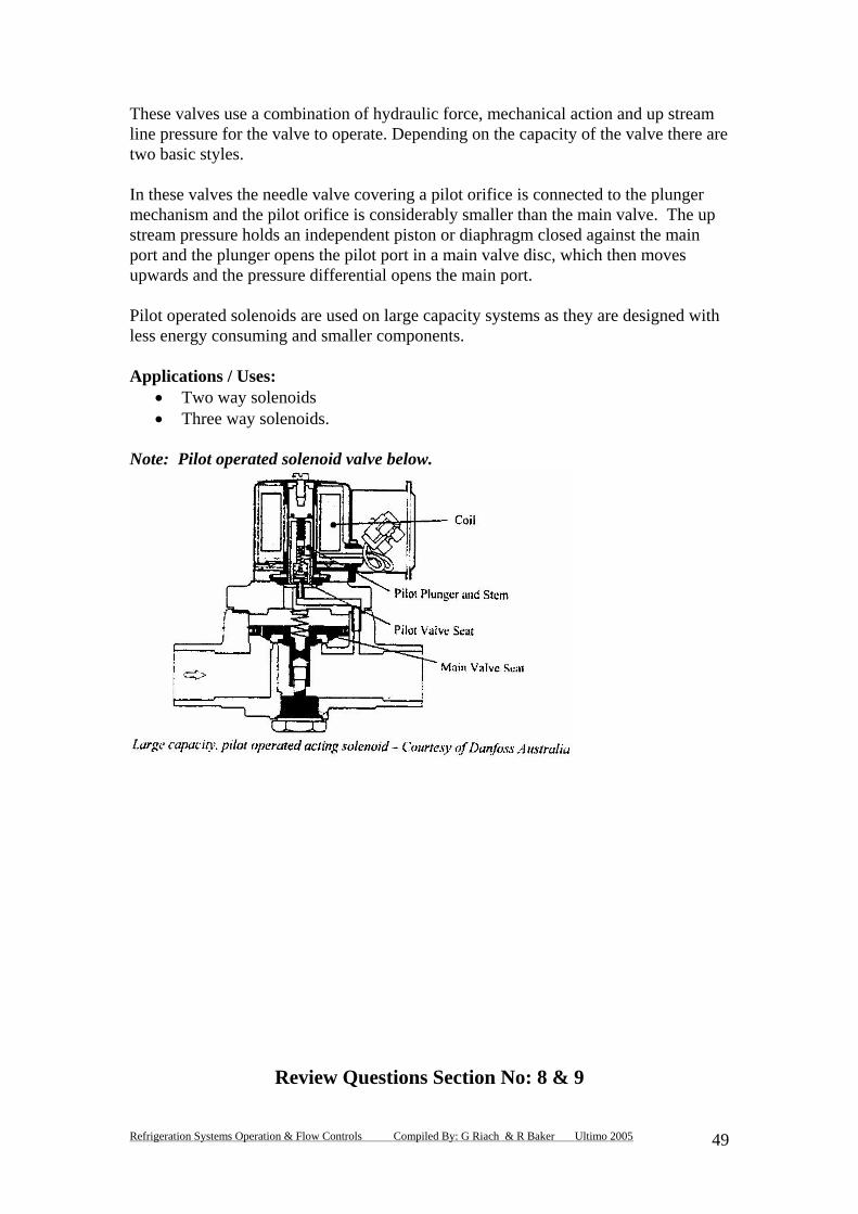
These valves use a combination of hydraulic force, mechanical action and up stream
these valves the needle valve covering a pilot orifice is connected to the plunger
ilot operated solenoids are used on large capacity systems as they are designed with
pplications / Uses: oids
.
ote: Pilot operated solenoid valve below.
line pressure for the valve to operate. Depending on the capacity of the valve there aretwo basic styles. Inmechanism and the pilot orifice is considerably smaller than the main valve. The upstream pressure holds an independent piston or diaphragm closed against the main port and the plunger opens the pilot port in a main valve disc, which then moves upwards and the pressure differential opens the main port. Pless energy consuming and smaller components. A
• Two way solen• Three way solenoids
N
Review Questions Section No: 8 & 9
Refrigeration Systems Operation & Flow Controls Compiled By: G Riach & R Baker Ultimo 2005
49

Q.1 Describe the function of a reversing valve:
Q.2 In what part of the system is the high pressure superheated vapour from the
discharge line diverted to when the reverse cycle air conditioner is on the
cooling cycle:
Q.3. Describe in your own words where a direct acting solenoid valve would be
used and its operating principle
Q.4 What care should you take when installing or replacing a reversing valve?
Q.5 List two types of solenoid valves:
Q.6 Where would the EPR valve be located on a refrigeration system?
Q.7 What is the main purpose of an evaporator pressure regulating valve?
Refrigeration Systems Operation & Flow Controls Compiled By: G Riach & R Baker Ultimo 2005
50

Q.8 Describe in your own words how you would adjust an EPR valve:
Q.9 State the purpose of the crankcase pressure regulating valve:
Q.10 Describe how you would adjust an CPR valve on a low temperature freezer
storage room:
Answers to Review Questions:
Refrigeration Systems Operation & Flow Controls Compiled By: G Riach & R Baker Ultimo 2005
51

Section No: 1, 2 & 3
Q.1 Enthalpy, Absolute pressure, Constant temperature, Specific volume & Density.
Q.2 Suction & Discharge pressures, Temperature of refrigerant entering the compressor and the metering device.
Q.3 To ensure that the liquid refrigerant entering the metering device is sub-
cooled.
Q.4 Adding a heat exchanger reduces flash gas and increases the evaporator surface area.
Q.5 Inlet guide vanes. Q.6 Face dampers or face bypass dampers. Three way modulating valves. Q.7 Three way bypass modulating water valve. Control fan speed by using
variable speed control. Cycling the condenser fan motor by temperature control.
Section No: 4 Q.1
• Reduce the high pressure sub-cooled liquid to a low pressure saturated liquid.
• Control the flow rate of refrigerant into the evaporator to match the evaporation rate.
• Ensure maximum capacity without starving or flooding the evaporator.
Q.2 Used on large industrial refrigeration systems.
Q.3 Cheap, trouble free, performs adequately in correct applications.
Q.4 Manually operated and requires a plant operator to adjust the valve.
Refrigeration Systems Operation & Flow Controls Compiled By: G Riach & R Baker Ultimo 2005
52

Q.5 Evaporator and spring pressure.
Q.6 Critical refrigerant charge.
Q.7
• Poor efficiency. • Evaporator load must be keep constant. • When evaporator load increases the valve tends to close. • When evaporator load decreases the valve tends to open.
Section No: 5
Q.1
• Domestic refrigerators/freezers. • Residential air conditioning systems. • Small commercial package air conditioning / refrigeration systems.
Q.2
• Smaller refrigerant charge. • Relatively trouble free; (no moving parts. • Low compressor starting torque.
Q.3
• Easy to block with solder • Does not modulate as load changes.
Q.4 Restricts or meters the flow of refrigerant due to its high frictional resistance of
the liquid flowing through. Q.5 Liquid refrigerant enters the outer casing and forces the orifice plate into a seat
that seals the outer edge of the plate eliminating bypass flow. Liquid refrigerant is forced through the small orifice which causes a pressure drop.
Q.6 Advantages: single moving part and no liquid receiver.
Refrigeration Systems Operation & Flow Controls Compiled By: G Riach & R Baker Ultimo 2005
53

Disadvantages: critical refrigerant charge and must be installed in the correct directional flow.
Q.7 Residential air conditioning. Section No: 6 Q.1
• P1 opening pressure from remote bulb • P2 Closing pressure from evaporator. • P3 Superheat adjustment spring (closing pressure).
Q.2 The evaporator would starve. Q.3 When the evaporator pressure drops exceeds 21kPa or when a multi-circuit
evaporator is used. Q.4
• Evaporator fully flooded under all conditions. • Maintains control over a wide operating temperature range. • Evaporator refrigerant velocity is maintained under all load conditions.
Q.5
• Liquid charged. • Gas charged. • .Cross charged.
Q.6
• Refrigerant type. • System application. • Evaporator design capacity. • TD of the evaporator. • Amount of sub-cooling available in the liquid line. • Pressure drop across the TX valve. • Refrigerant distributor if fitted.
Q.7
1. Determine the actual temperature at the TX valve sensing bulb. 2. With a set of service gauges determine the saturated temperature of refrigerant
leaving the evaporator. 3. Superheat is found by deducting step 2 from step 1.
Q.8 To ensure an equal refrigerant feed to each of the evaporators circuits. Q.9
Refrigeration Systems Operation & Flow Controls Compiled By: G Riach & R Baker Ultimo 2005
54

• Centrifugal. • Pressure drop. • Manifold. • Venturi.
Q.10 Immediately after the metering device.
Section No: 7
Q.1 Flooded evaporators.
Oil is collected and drops to the bottom of the oil trap until the level allows the ball float to open. High refrigerant pressure forces the collected oil back to the compressor sump.
Q.2 Centrifugal air conditioning system. Q.3 Advantages:
• Higher rate of heat transfer than the dry expansion type. • Can be used on multiple evaporator systems.
Disadvantages:
• Higher refrigerant charge. • Flooded evaporators take a long time to be defrosted.
Q.4 The liquid level is operated by a float ball that opens on fall in the evaporator liquid level. The level is maintained to the rate at which the refrigerant vapour is drawn from the evaporator by the compressor. Q.5 Heater and bi-metal strip. Spring loaded orifice needle.. Q.6 Advantages:
• Minimises oil logging under all load conditions by maintaining evaporator velocity.
• Fully flooded evaporator under all load conditions. • Control is maintained over a wide operating temperature range.
Section No: 8 & 9
Refrigeration Systems Operation & Flow Controls Compiled By: G Riach & R Baker Ultimo 2005
55
Q.1 Reversing valves are a special form of four way solenoid valve and are used to control the flow of refrigerant in reverse cycle air conditioning systems. Q.2 The condenser which is located outside. Q.3 Small capacity up to 10 kW, 6mm port size and 10mm line size. Relies on electromagnetism to lift the armature and open the port. Q.4 Care should be taken not to overheat the valve when welding. Q.5 Directed acting and pilot operated. Q.6 In the suction line as close to the evaporator as possible. Q.7 To maintain a pre-determined evaporator pressure temperature. Q.8
• Connect a compound gauge to the EPR valve connection. • Fit another compound service gauge to the suction service valve. • Using a screw driver or allen key open the valve slightly off its seat. • Compressor gauge should indicate a lower pressure than the EPR
valve. • When the compressor gauge falls below required EPR valve the valve
should be adjusted as follows: (a) Increasing pressure: turn the adjustment screw in a clockwise
direction. (b) Decreasing pressure: turn the adjustment screw in an anti-clockwise
direction. Q.9 To prevent the compressor drive motor from overloading immediately after a defrost cycle. Q.10
• Make sure the system is on a defrost cycle. • Place a “clamp on” ampere-meter around one of the motors active
terminals. • Fit a set of gauges at the compressor suction service valve. • When the defrost cycle is complete and the condensing unit starts up:
adjust the CPR valve so that the motor is drawing 100% of its FLA.
Refrigeration Systems Operation & Flow Controls Compiled By: G Riach & R Baker Ultimo 2005
56