System Design Evaluation Work Plansrsnesite.com/download/rd/ra_work_plans/RDWP Att E … · ·...
29
SRSNE Site Group Remedial Design Work Plan Attachment E System Design Evaluation Work Plan Solvents Recovery Service of New England, Inc. (SRSNE) Superfund Site Southington, Connecticut November 2010
Transcript of System Design Evaluation Work Plansrsnesite.com/download/rd/ra_work_plans/RDWP Att E … · ·...

SRSNE Site Group
Remedial Design Work Plan Attachment E
System Design Evaluation Work Plan
Solvents Recovery Service of New England, Inc.
(SRSNE) Superfund Site
Southington, Connecticut
November 2010

Remedial Design Work Plan Attachment E System Design Evaluation Work Plan Solvents Recovery Service of New England, Inc. (SRSNE) Superfund Site Southington, Connecticut
Prepared for:
SRSNE Site Group
Prepared by:
TerraTherm, Inc.
10 Stevens Road
Fitchburg
MA 01420
Phone: (978) 343-0300
Fax: (978) 343-2727
Our Ref.:
9-101
Date:
November 2010
i
Table of Contents
Executive Summary iii
1. Introduction 1
2. Materials Compatibility Study 2
2.1 Introduction 2
2.2 Identification of Chemical Composition of DNAPL Sample 2
2.3 Corrosion Study 3
2.3.1 Phase 1 – Potential for Corrosion near a Heater Well 4
2.3.2 Phase 2 – Potential for Corrosion due to Condensation 7
2.4 Reporting 9
3. Numerical Calculations of Heating and Sensitivity Study 11
3.1 Introduction 11
3.2 Description of calculations 11
3.2.1 Calculation Description 11
3.2.1.1 Water Mass Balance Methods 13
3.2.1.2 Energy Balance Estimation Methods 16
3.2.2 Site-Specific Calculations Set Up 19
3.3 Calculation Results for Base Case Scenario 19
3.3.1 Energy Balance Calculations 20
3.3.2 Average Temperature Development 20
3.3.3 Average Saturation Development 20
3.4 Sensitivity Analysis 20
3.4.1 Heater Spacing versus Duration 20
3.4.2 Vapor Cap Thickness 21
ii
Table of Contents
3.4.3 Horizontal and Vertical Groundwater Flux 21
3.4.4 Heater Boosting 21
3.5 Basic System Design Parameters 21
3.6 Reporting 22
Table
E-1 Analyses expected to be performed on the DNAPL sample
Figures
E-1 Testing Setup for First Phase of Corrosion Study.
E-2 Testing Setup for Second Phase of Corrosion Study
E-3 Schematic Cross-section of a Possible Calculation Setup for the SRSNE site
E-4 Mass Balance Principles for Water (one Layer Shown for Simplicity)
E-5 Energy Balance Schematic (One Layer Shown for Simplicity)

iii
System Design Evaluation Work Plan
SRSNE Superfund Site Southington, Connecticut
Executive Summary
The System Design Evaluation Work Plan was prepared to address Section V.C.1.e of the Statement of Work (SOW) states that “an evaluation may be conducted to confirm design specifications to achieve non-aqueous phase liquid (NAPL) performance standards, evaluate methods to control groundwater migration into the treatment zone, confirm vapor treatment equipment sizing, and evaluate the potential for equipment corrosion.” The focus of this work plan is to describe the scope and approach for undertaking two design evaluations to support the In-Situ Thermal Desorption (ISTD) system design:
A materials compatibility study to evaluate the potential for corrosion of subsurface and above ground system components (Section 2)
Numerical calculations upon which to base the sizing of the heating and treatment equipment (Section 3). Furthermore, the calculations will be used to determine the sensitivity of heater spacing, vapor cap thickness (i.e., R-value), etc., on the total timeframe for the thermal remediation
Materials Compatibility Study
A bench-scale materials compatibility study will be performed on a sample of the dense non-aqueous phase liquid (DNAPL) from the Overburden NAPL Area at the Site. The objectives of the treatability study are to provide information on the compatibility of various well and piping materials with the corrosive conditions that could be created during heating/treating of the organic compounds present in the residual layer. This information will be used to select appropriate materials and designs for construction of the heater wells, monitoring points, manifold piping, and off-gas treatment equipment for the full-scale remediation. A specialty treatability study laboratory, Kemron Environmental Services (Kemron) of Atlanta, Georgia, will perform the bench-scale treatability study.
The study will include the following components:
Identification of the chemical composition and thermal value of a representative DNAPL sample from the site.
iv
System Design Evaluation Work Plan
SRSNE Superfund Site Southington, Connecticut
Generation of expected corrosion conditions near the heater wells and testing of a variety of materials to estimate their rate of corrosion and compatibility for use in the subsurface components of the ISTD system.
Simulation of corrosion condensing conditions that may occur within above ground piping and equipment and testing of a variety of materials to estimate their rate of corrosion and compatibility for use in the above ground components of the ISTD system.
The results of these studies will be incorporated into the conceptual design of the ISTD system.
Energy Balance Calculations
Water and energy balance calculations will be prepared to investigate the importance of groundwater flux, heater spacing, power input, heater boosting, and thickness of vapor cover for the temperatures that can be achieved in-situ. The water and energy balance will estimate the addition, removal, and loss of energy in each layer of the site separately, with the layers exchanging both fluids (water, steam, air) and energy along their boundaries. The calculations will also estimate crucial heat losses along the top, sides, and bottom of the treatment zone, and the impact of groundwater flow into the treatment area, such that relatively accurate total energy demands are derived. The results of these calculations will include sizing parameters for the thermal treatment system and provide the starting basis for design of the ISTD system including the following:
Size of ISTD power supply Condensed liquid rate
Vapor extraction rate Water treatment rate
Non-condensable vapor rate Heat exchanger sizing, vapor
Condensable vapor (steam) rate Heat exchanger sizing, water
Liquid extraction rate

1
System Design Evaluation Work Plan
SRSNE Superfund Site Southington, Connecticut
1. Introduction
This document has been prepared on behalf of the SRSNE Site Group, an unincorporated association of Settling Defendants to a Consent Decree (CD) and Statement of Work (SOW) for the Remedial Design/Remedial Action (RD/RA) at the Solvents Recovery Service of New England, Inc. (SRSNE) Superfund Site in Southington, Connecticut (Site). The CD was lodged on October 30, 2008 with the United States District Court for the District of Connecticut in connection with Civil Actions No. 3:08cv1509 (SRU) and No. 3:08cv1504 (WWE).
Section V.C.1 of the SOW suggests that certain pre-design studies be undertaken prior to the design of the thermal treatment remedy for the Site. Specifically, Section V.C.1.e of the SOW states that “an evaluation may be conducted to confirm design specifications to achieve Non Aqueous Phase Liquid (NAPL) performance standards, evaluate methods to control groundwater migration into the treatment zone, confirm vapor treatment equipment sizing, and evaluate the potential for equipment corrosion.” This System Design Evaluation Work Plan has been prepared to describe the scope and approach for undertaking two design evaluations to support the In-Situ Thermal Desorption (ISTD) system design:
1. A materials compatibility study to evaluate the potential for corrosion of subsurface and above ground system components (Section 2),
2. Numerical calculations upon which to base the sizing of the heating and treatment equipment (Section 3). Furthermore, the calculations will be used to determine the sensitivity of heater spacing, vapor cap thickness (i.e., R-value), etc. on the total timeframe for the thermal remediation
The following work plan describes these evaluations.

2
System Design Evaluation Work Plan
SRSNE Superfund Site Southington, Connecticut
2. Materials Compatibility Study
2.1 Introduction
A bench-scale materials compatibility study will be performed on a sample of the Dense Non Aqueous Phase Liquid (DNAPL) from the Overburden NAPL Area at the SRSNE Site. The objectives of the treatability study are to provide information on the compatibility of various well and piping materials with the corrosive conditions that could be created during heating/treating of the organic compounds present in the residual layer. This information will be used to select appropriate materials and designs for construction of the heater wells, monitoring points, manifold piping, and off-gas treatment equipment for the full-scale remediation.
A specialty treatability study laboratory, Kemron Environmental Services (Kemron), Atlanta, GA will perform the bench-scale treatability study. The following outlines the procedures that will be used for the treatability study.
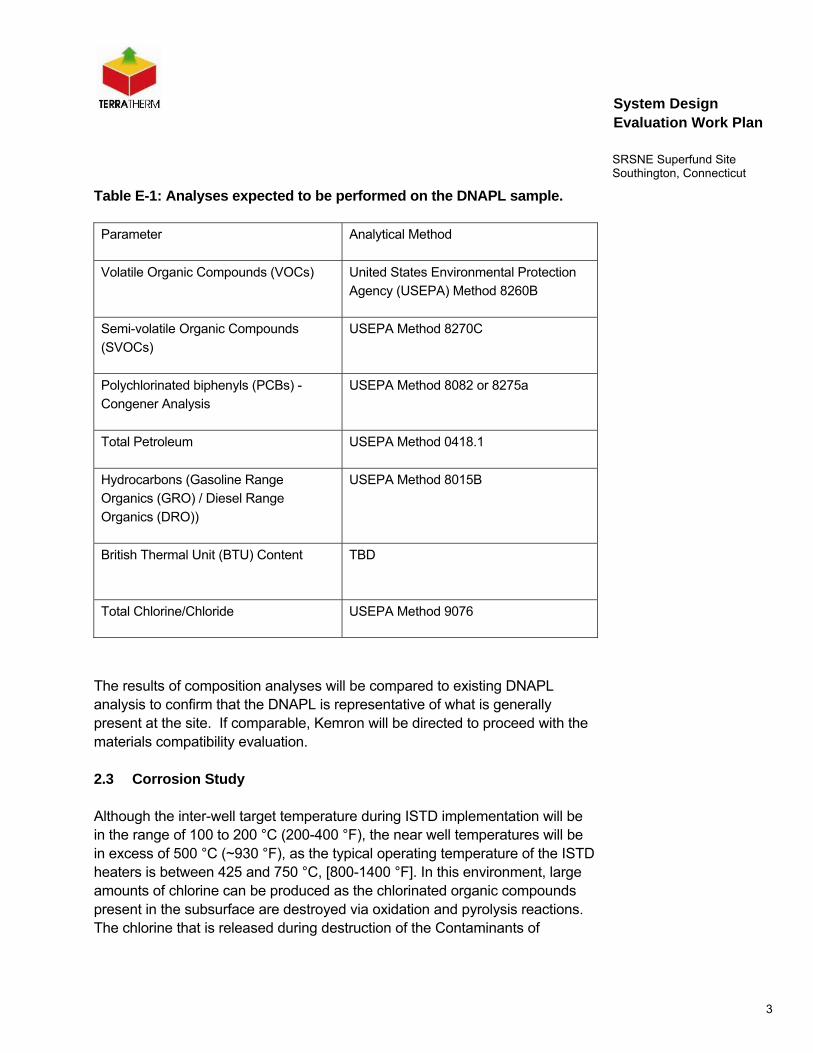
2.2 Identification of Chemical Composition of DNAPL Sample
The first task will be to determine the chemical composition and the relative percentages, on a mass basis, of each compound present in the DNAPL sample(s) selected for the materials compatibility study. The DNAPL sample (s) will be collected during the Overburden NAPL Delineation effort as part of the pre-design studies (see Attachment A of the RDWP for details) and results of this analysis will be compared with available information on the general composition of DNAPL from the Site to verify that the selected sample (s) are representative. The composition analysis will also be used to predict the fuel value of the NAPL and the chloride loading rate. This information will be used to design and size the vapor treatment system components and predict the amount of chlorine/hydrogen chloride gas that may be liberated and caustic that will be consumed for acid scrubbing in the event that thermal oxidation is utilized for vapor treatment.
3
System Design Evaluation Work Plan
SRSNE Superfund Site Southington, Connecticut
Table E-1: Analyses expected to be performed on the DNAPL sample.
Parameter Analytical Method
Volatile Organic Compounds (VOCs)
United States Environmental Protection
Agency (USEPA) Method 8260B
Semi-volatile Organic Compounds
(SVOCs)
USEPA Method 8270C
Polychlorinated biphenyls (PCBs) -
Congener Analysis
USEPA Method 8082 or 8275a
Total Petroleum USEPA Method 0418.1
Hydrocarbons (Gasoline Range
Organics (GRO) / Diesel Range
Organics (DRO))
USEPA Method 8015B
British Thermal Unit (BTU) Content
TBD
Total Chlorine/Chloride USEPA Method 9076
The results of composition analyses will be compared to existing DNAPL analysis to confirm that the DNAPL is representative of what is generally present at the site. If comparable, Kemron will be directed to proceed with the materials compatibility evaluation.
2.3 Corrosion Study
Although the inter-well target temperature during ISTD implementation will be in the range of 100 to 200 °C (200-400 °F), the near well temperatures will be in excess of 500 °C (~930 °F), as the typical operating temperature of the ISTD heaters is between 425 and 750 °C, [800-1400 °F]. In this environment, large amounts of chlorine can be produced as the chlorinated organic compounds present in the subsurface are destroyed via oxidation and pyrolysis reactions. The chlorine that is released during destruction of the Contaminants of

4
System Design Evaluation Work Plan
SRSNE Superfund Site Southington, Connecticut
Concern (COCs) can combine with water to produce hydrogen chloride gas and/or hydrochloric acid (HCl). Thus, if the hot vapors condense along the heater wells or in the manifold piping, liquid HCl could be produced. Repeated boiling and condensing of these vapors would result in very corrosive environments and potentially, excessive corrosion of the well and manifold piping materials.
The studies outlined below are designed to gain insight into the issues of material compatibility and degree of corrosion that might occur for various well, manifold piping and vapor treatment equipment materials of construction during ISTD treatment of the specific COCs present within the Target Treatment Zone (TTZ). To simulate the range of conditions that could be present in the subsurface, the corrosion study is divided into two phases. The first phase examines the conditions in the immediate vicinity of a very hot heater well and the second phase examines the conditions that could occur in the subsurface wells, manifold piping, and vapor treatment equipment if the hot vapors were to condense and boil repeatedly.
2.3.1 Phase 1 – Potential for Corrosion near a Heater Well
Figure 1 shows the setup for the first phase of the corrosion study. The DNAPL sample will be placed in a container (e.g., Erlenmeyer flask) for boiling and generation of off-gases. The target volume desired for the study is ~1 gal. In the event that a sufficient volume of liquid DNAPL is not available, a container (or containers) loaded with DNAPL-rich soil will be heated in an oven to produce DNAPL-laden vapors. It is estimated that approximately 3 5-gallon pails of DNAPL-rich soil would be required for the study.
Air and steam will be metered into the test set-up to simulate in-situ conditions. The generated off gases, will be passed through a second oven containing a cylinder packed with clean sand. The temperature of the oven and material in the oven will be pre-heated prior to the start of the thermal treatment tests to 700 °C (~1300 °F). Thus, when off-gasses generated during boiling of the DNAPL are passed through the very hot packed bed reactor, they will be exposed to conditions found close to a heater well and a portion of the organic fraction of the compounds present in the vapor stream will be destroyed, leaving chlorine and/or hydrogen chloride gas.

5
System Design Evaluation Work Plan
SRSNE Superfund Site Southington, Connecticut
The chlorine laden off-gas will then pass out of reactor bed and into a second cylinder, also in the oven, packed with sand and samples of the various materials being considered for the wells and piping. This will provide a way to evaluate the resistance of these materials to the corrosive environment that exists near a heater well.
After the vapors exit the cylinder containing the material coupons and the oven, they will be sent through a condenser and the condensate will be collected. The final step is to send the non-condensable vapor stream through a Granular Activated Carbon (GAC) filter to remove any remaining COCs before the vapors are released to the atmosphere. The condensate will be collected from the DNAPL boiling test and used in the second phase of the corrosion study as described below.
SteamGenerator
HeatSource
MuffleFurnace
VaporFlow
700 oCNear Well
Conditions
Heat Tapeand
Insulation
Cylinder PackedWith Sand
H2O
Out
H2O
in
Condenser
CondensateCollection
AirWater
DNAPLSource
Cylinder PackedWith Sand and
Material CouponsGAC
AirOut
Figure E-1. Testing Setup for First Phase of Corrosion Study
Note that this phase is designed to expose material coupons to very hot and potentially corrosive gases that could be generated near the heater wells and to collect condensate for the second phase of corrosion testing.
6
System Design Evaluation Work Plan
SRSNE Superfund Site Southington, Connecticut
A subcontracted metallurgist (to be determined) will be consulted to assist with selection of materials for compatibility/corrosion testing. The materials that will be tested may include:
Carbon steel,
304l/316 Stainless Steel,
310 Stainless Steel,
Inconel 600 (or similar),
AL6XN,
RA330,
Hastelloy X, and
Hastelloy C276
The total duration that the material coupons will be exposed to the very hot/corrosive gases will be approximately 5 to 10 days. This should be sufficient to evaluate the corrosion resistance of the various materials in the near well environment and allow projection of corrosion rates for extended exposure.
Upon completion of the thermal evaluation tests, the cylinder containing the material coupons will be cooled and opened and the coupons will be inspected to determine their resistance to corrosive conditions near the heater wells. Post-testing weight and thickness will be compared with pre-test weight and thickness to determine the amount of material loss/gain. The samples will then be cleaned and packaged for shipment to a metallurgical laboratory for detailed metallurgical inspection. Inspection and testing will depend on the as-received condition of the sample, but may include:
• Metallographic cross-sections,
• Exterior surface and interior microscopic inspections,
• Determination of intergranular attack mechanism (if present),
7
System Design Evaluation Work Plan
SRSNE Superfund Site Southington, Connecticut
• Metal loss/gain evaluation & estimate of service life.
2.3.2 Phase 2 – Potential for Corrosion due to Condensation
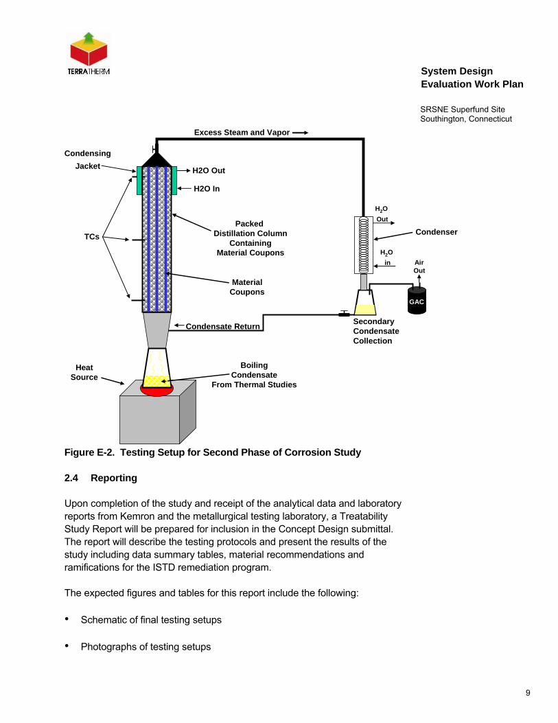
Figure 2 presents the setup that will be used to evaluate the resistance of the materials under consideration to corrosive conditions associated with zones where there is repeated condensing and boiling of the vapors.
The condensate collected during the Phase 1 corrosion testing will be heated to boiling. The steam and vapors produced during boiling will be captured in a distillation column containing coupons (e.g., rods or strips) of the materials being considered for the wells piping, and certain process equipment components. As the steam rises into the column and cools, condensation will form along the length of the column and on the surface of the material coupons. The condensate will be allowed to drain back down into the reservoir where it will be re-heated and boiled. The repeated boiling and condensing that will occur in the reservoir and column will simulate potential conditions in the subsurface, piping and some of the treatment equipment where repeated condensation and re-boiling may occur.
The distillation column will be fitted with a series of temperature sensors along the length of the column in order to monitor temperatures within the column. The pH of the condensate will also be periodically measured over the course of the boiling test.
The duration of this phase of the corrosion study will depend on the quantity of condensate produced during the thermal treatment evaluation and how efficient the setup is in condensing and capturing all of the steam. The overall object will be to run the test for 5 to 10 days. This should provide sufficient time to evaluate the resistance of the various materials to condensation corrosion and allow projection of corrosion rates for extended exposure.
Again, a metallurgist will be consulted to assist with selection of materials for compatibility/corrosion testing for this phase of the test. The materials that will be tested in this phase may include:
Carbon steel,
304/316 Stainless Steel,
Inconel 600 (or similar),
8
System Design Evaluation Work Plan
SRSNE Superfund Site Southington, Connecticut
2205 Duplex Stainless Steel,
AL6XN,
Hastelloy X,
Hastelloy C276, and
Fiberglass (epoxy and/or vinyl ester lined).
Upon completion of the condensing phase of the thermal evaluation tests, the cylinder containing the material coupons will be cooled and opened and the coupons will be inspected to determine their resistance to potential condensing conditions. Post-testing weight and thickness will be compared with pre-test weight and thickness to determine the amount of material loss/gain.
Fiberglass samples will be packaged for shipment to the manufacturer’s application engineering department for inspection and evaluation. The metal samples will then be cleaned and packaged for shipment to a metallurgical laboratory for detailed metallurgical inspection. Metallurgical inspection and testing will depend on the as-received condition of the sample, but may include:
• Metallographic cross-sections,
• Exterior surface and interior microscopic inspections,
• Determination of intergranular attack mechanism (if present),
• Determination of preferential phase attack (for duplex alloys),
• Metal loss/gain evaluation & estimate of service life.
9
System Design Evaluation Work Plan
SRSNE Superfund Site Southington, Connecticut
MaterialCoupons
Packed Distillation Column
ContainingMaterial Coupons
BoilingCondensate
From Thermal Studies
HeatSource
TCs
Condensing
Jacket H2O Out
H2O In
H2O
Out
H2O
in
Condenser
SecondaryCondensateCollection
GAC
AirOut
Excess Steam and Vapor
Condensate Return
Figure E-2. Testing Setup for Second Phase of Corrosion Study
2.4 Reporting
Upon completion of the study and receipt of the analytical data and laboratory reports from Kemron and the metallurgical testing laboratory, a Treatability Study Report will be prepared for inclusion in the Concept Design submittal. The report will describe the testing protocols and present the results of the study including data summary tables, material recommendations and ramifications for the ISTD remediation program.
The expected figures and tables for this report include the following:
• Schematic of final testing setups
• Photographs of testing setups
10
System Design Evaluation Work Plan
SRSNE Superfund Site Southington, Connecticut
• Photographs of condensate
• Tables summarizing chemical composition of DNAPL
• Plot of pH of condensate over the course of the boiling/condensing portion of the test
• Tables summarizing material losses during test, estimated corrosion rates, and service lives.
• Photographs summarizing post-test condition of material samples
The mentioned figures and tables are subject to change depending of the actual results from the laboratory study.
The materials compatibility study report will be submitted with the Concept Design package as an attachment.

11
System Design Evaluation Work Plan
SRSNE Superfund Site Southington, Connecticut
3. Numerical Calculations of Heating and Sensitivity Study
3.1 Introduction
The purpose of the water and energy balance calculations is to investigate the importance of groundwater flux, heater spacing, power input, heater boosting, and thickness of vapor cover for the temperatures that can be achieved in-situ. Calculation output includes sizing parameters for the thermal treatment system.
A water and energy balance has been developed by TerraTherm to estimate the addition, removal, and loss of energy in each layer of the site separately, with the layers exchanging both fluids (water, steam, air) and energy along their boundaries. The calculations also estimate crucial heat losses along the top, sides, and bottom of the treatment zone, and the impact of groundwater flow into the treatment area, such that relatively accurate total energy demands are derived.
These water and energy balance calculations are referred to in the following sections as the “calculations.”
The result of the calculations will be used to select the heating approach and for sizing of the off-gas treatment system.
In the following sections the basic calculation setup is described along with the specific goals expected to be derived on the basis of the conducted water and energy balance calculations.
3.2 Description of calculations
3.2.1 Calculation Description
The calculations are based on simplified mass and energy balance principles relevant for ISTD operation. The calculations can include up to 9 layers, each with different input and derived parameters, including:
• Surface area of the treatment zone
• Depth of each calculation layer
12
System Design Evaluation Work Plan
SRSNE Superfund Site Southington, Connecticut
• Area of perimeter of each calculation layer
• Porosity of each calculation layer
• Initial water saturation in each calculation layer
• Initial bulk density for each calculation layer
• Initial heat capacity for each calculation layer
• Initial thermal conductivity for each calculation layer
During the calculations, parameters such as thermal conductivity and heat capacity are changed automatically based on the water saturation of each layer, This means, for instance, that as a zone is drying out due to boiling and steam removal, the water saturation is reduced, and therefore both the heat capacity and thermal conductivity are reduced, such that only the remaining water contributes to these parameters. This gives a more realistic heating prediction than if constant values are assumed.
13
System Design Evaluation Work Plan
SRSNE Superfund Site Southington, Connecticut
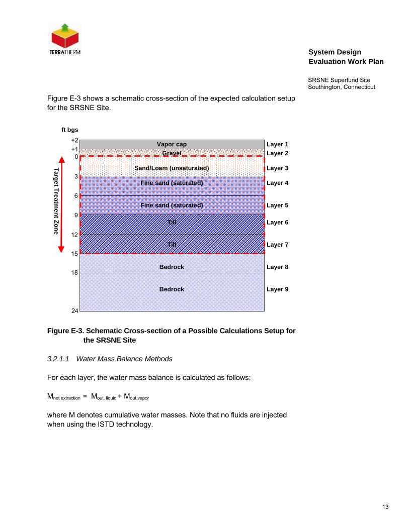
Figure E-3 shows a schematic cross-section of the expected calculation setup for the SRSNE Site.
ft bgs
+1
Targ
et T
reatm
en
t Zo
ne
0
3
6
9
12
15
18
24
Vapor cap
Gravel
Sand/Loam (unsaturated)
Fine sand (saturated)
Fine sand (saturated)
Till
Till
Bedrock
Bedrock
+2Layer 1
Layer 2
Layer 3
Layer 4
Layer 5
Layer 6
Layer 7
Layer 8
Layer 9
Figure E-3. Schematic Cross-section of a Possible Calculations Setup for the SRSNE Site
3.2.1.1 Water Mass Balance Methods
For each layer, the water mass balance is calculated as follows:
Mnet extraction = Mout, liquid + Mout,vapor
where M denotes cumulative water masses. Note that no fluids are injected when using the ISTD technology.

14
System Design Evaluation Work Plan
SRSNE Superfund Site Southington, Connecticut
The mass removal in the liquid form is a simple summation of flow rate measurements:
Mout, liquid = Σ (mliquid x ∆t)
where the values for the flow rate mliquid is determined manually for each operational phase.
For this site, small amounts of entrained liquids are expected in the vapor extraction system. No pumping wells are included in the base scenario. Influx of groundwater in the calculations will be based on numbers from the site-specific groundwater model developed by Blasland, Bouck & Lee, Inc. an ARCADIS Company and presented to the USEPA and CTDEP in support of the NTCRA 2 groundwater extraction and treatment design1.
The water mass removal in the form of vapor (steam, water vapor) is calculated as follows:
Mout,vapor = Σ (msteam x ∆t) = Σ (mtotal vapor – mnon-cond ) x ∆t
where msteam is the vapor flow rate made up of steam, mtotal vapor is the total incoming vapor flow rate, and mnon-cond is the vapor flow rate minus the steam component (air mostly).
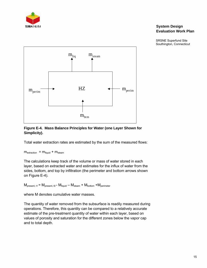
For these simulations, the steam extraction rates are calculated based on the energy injected by the ISTD system. The equation calculating the ratio between injected energy and extracted steam is derived based on observations made on several recent full-scale ISTD projects. Figure E-4 illustrates the streams that take part in the water mass balance in the Heated Zone (HZ).
1 BBL (2006): Evaluation of Groundwater Flow During Potential Thermal Remedy, SRSNE Site in
Southington, Connecticut
15
System Design Evaluation Work Plan
SRSNE Superfund Site Southington, Connecticut
HZ mperimmperim
mbtm
msteammliq
Figure E-4. Mass Balance Principles for Water (one Layer Shown for Simplicity).
Total water extraction rates are estimated by the sum of the measured flows:
mextraction = mliquid + msteam
The calculations keep track of the volume or mass of water stored in each layer, based on extracted water and estimates for the influx of water from the sides, bottom, and top by infiltration (the perimeter and bottom arrows shown on Figure E-4).
Mpresent, t1 = Mpresent, t0 - Mliquid – Msteam + Mbottom +Mperimeter
where M denotes cumulative water masses.
The quantity of water removed from the subsurface is readily measured during operations. Therefore, this quantity can be compared to a relatively accurate estimate of the pre-treatment quantity of water within each layer, based on values of porosity and saturation for the different zones below the vapor cap and to total depth.

16
System Design Evaluation Work Plan
SRSNE Superfund Site Southington, Connecticut
For the SRSNE-Site it will be assumed that the surface cover is intact and graded to promote runoff to minimize any standing surface water thus reducing the potential for infiltration from the top through the vapor cover.
3.2.1.2 Energy Balance Estimation Methods
Cumulative energy (E) is calculated as a summation of enthalpy fluxes (Q):
E = Σ (Q x ∆t)
An estimated energy balance is maintained for each layer in the calculations based on energy delivered by the ISTD-heaters, energy extracted in the vapor and liquid streams and heat loss to the areas outside of the Heated Zone (HZ).
Ein = Eout + Estorage + Eloss
The energy fluxes are related for each time step as follows:
Qin = Qout + Qstorage + Qloss
Where Q denotes enthalpy flux (in BTU/hr). Figure E-5 shows the schematic energy balance for one layer.
17
System Design Evaluation Work Plan
SRSNE Superfund Site Southington, Connecticut
HZ QperimQperim
Qbtm
QsteamQairQliqQin Qcap
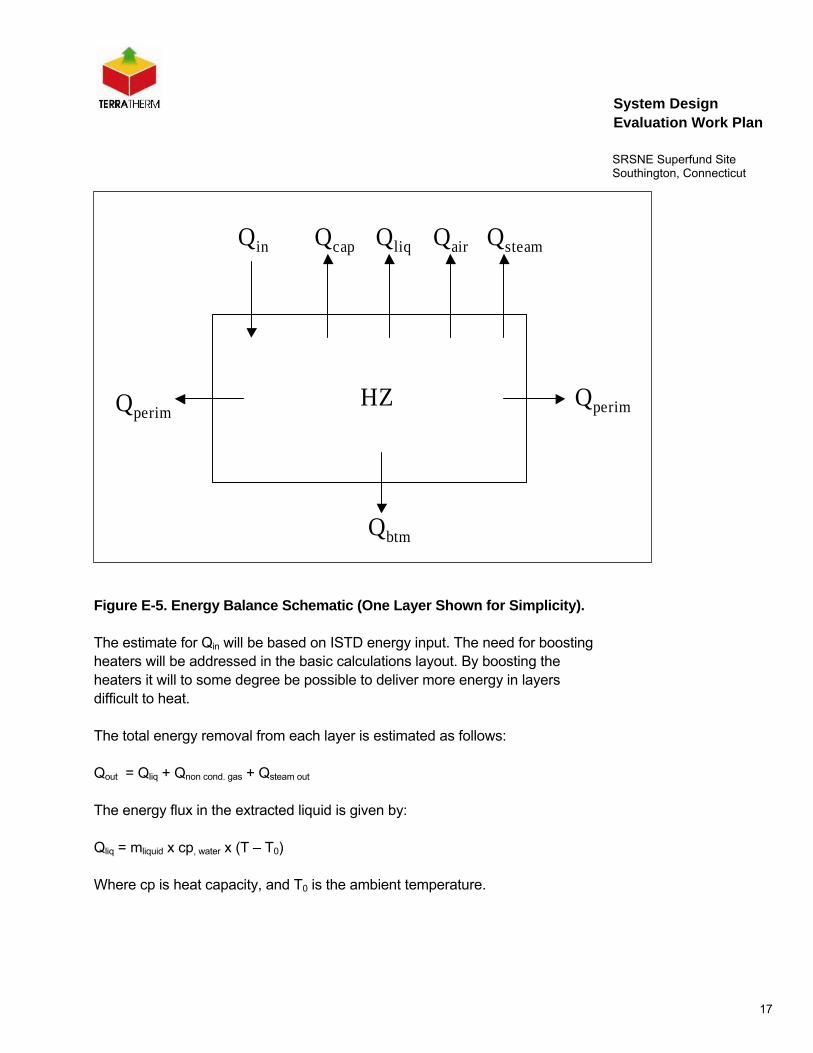
Figure E-5. Energy Balance Schematic (One Layer Shown for Simplicity).
The estimate for Qin will be based on ISTD energy input. The need for boosting heaters will be addressed in the basic calculations layout. By boosting the heaters it will to some degree be possible to deliver more energy in layers difficult to heat.
The total energy removal from each layer is estimated as follows:
Qout = Qliq + Qnon cond. gas + Qsteam out
The energy flux in the extracted liquid is given by:
Qliq = mliquid x cp, water x (T – T0)
Where cp is heat capacity, and T0 is the ambient temperature.

18
System Design Evaluation Work Plan
SRSNE Superfund Site Southington, Connecticut
For the extracted vapor stream, the energy flux in vapor and steam is estimated as follows:
Qnon cond. gas = mair x cp, air x (T – T0)
Qsteam out = mcondensate x ∆Hsteam-ambient
Where m is mass flux, H is specific enthalpy (in BTU/lb), cp is heat capacity (in BTU/lb/F), and T is temperature. The enthalpy of the steam can be estimated from steam tables.
The actual heat loss cannot be calculated using accurate measures. An estimate can be made based on thermal profiles at the bottom and top of each layer, and along the perimeter, using the following equation:
Qheat loss = A x KT x dT/dz
where A is the surface area through which energy is conducted, KT is the thermal conductivity of the subsurface material, and dT/dz is the temperature gradient across the surface also expressed as (T1-T2)/(z1-z2).
For the loss through the vapor cap, the temperature difference between the top and bottom of the layer can be used to calculate the gradient. For the calculations, it is assumed that the top of the vapor cap remains near ambient temperatures due to a combination of wind cooling, ventilation, and simple heat radiation. The area of the heated zone may be estimated based on the zone designated HZ, which is slightly larger than the footprint of the wells due to the heat migration outside.
Heat loss through the bottom and sides are accounted for in a similar manner. The layers exchange energy by thermal conduction such that energy leaves the warmer layer and enters the cooler layer.
All heat migration through the sides and through the vapor cap and the bottom layer are considered lost from the calculation domain. Heat migration from the bottom of a layer and into the top of the underlying layer remains as energy in the calculations if both layers are in the heated zone.
19
System Design Evaluation Work Plan
SRSNE Superfund Site Southington, Connecticut
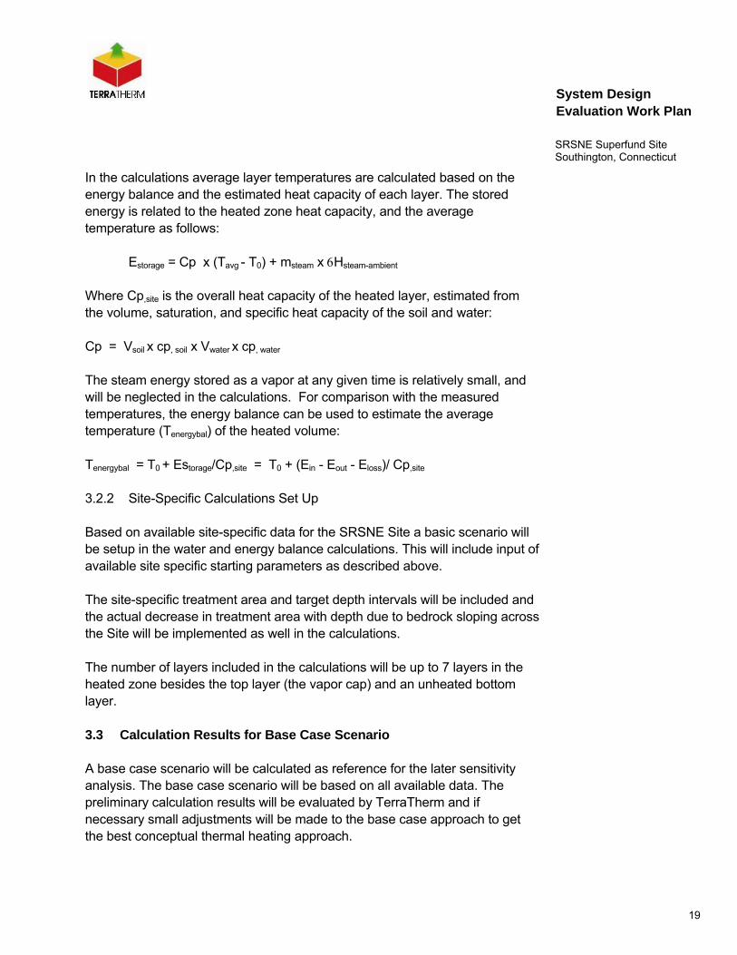
In the calculations average layer temperatures are calculated based on the energy balance and the estimated heat capacity of each layer. The stored energy is related to the heated zone heat capacity, and the average temperature as follows:
Estorage = Cp x (Tavg - T0) + msteam x Hsteam-ambient
Where Cp,site is the overall heat capacity of the heated layer, estimated from the volume, saturation, and specific heat capacity of the soil and water:
Cp = Vsoil x cp, soil x Vwater x cp, water
The steam energy stored as a vapor at any given time is relatively small, and will be neglected in the calculations. For comparison with the measured temperatures, the energy balance can be used to estimate the average temperature (Tenergybal) of the heated volume:
Tenergybal = T0 + Estorage/Cp,site = T0 + (Ein - Eout - Eloss)/ Cp,site
3.2.2 Site-Specific Calculations Set Up
Based on available site-specific data for the SRSNE Site a basic scenario will be setup in the water and energy balance calculations. This will include input of available site specific starting parameters as described above.
The site-specific treatment area and target depth intervals will be included and the actual decrease in treatment area with depth due to bedrock sloping across the Site will be implemented as well in the calculations.
The number of layers included in the calculations will be up to 7 layers in the heated zone besides the top layer (the vapor cap) and an unheated bottom layer.
3.3 Calculation Results for Base Case Scenario
A base case scenario will be calculated as reference for the later sensitivity analysis. The base case scenario will be based on all available data. The preliminary calculation results will be evaluated by TerraTherm and if necessary small adjustments will be made to the base case approach to get the best conceptual thermal heating approach.
20
System Design Evaluation Work Plan
SRSNE Superfund Site Southington, Connecticut
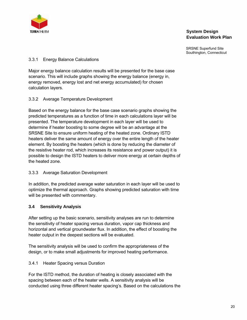
3.3.1 Energy Balance Calculations
Major energy balance calculation results will be presented for the base case scenario. This will include graphs showing the energy balance (energy in, energy removed, energy lost and net energy accumulated) for chosen calculation layers.
3.3.2 Average Temperature Development
Based on the energy balance for the base case scenario graphs showing the predicted temperatures as a function of time in each calculations layer will be presented. The temperature development in each layer will be used to determine if heater boosting to some degree will be an advantage at the SRSNE Site to ensure uniform heating of the heated zone. Ordinary ISTD heaters deliver the same amount of energy over the entire length of the heater element. By boosting the heaters (which is done by reducing the diameter of the resistive heater rod, which increases its resistance and power output) it is possible to design the ISTD heaters to deliver more energy at certain depths of the heated zone.
3.3.3 Average Saturation Development
In addition, the predicted average water saturation in each layer will be used to optimize the thermal approach. Graphs showing predicted saturation with time will be presented with commentary.
3.4 Sensitivity Analysis
After setting up the basic scenario, sensitivity analyses are run to determine the sensitivity of heater spacing versus duration, vapor cap thickness and horizontal and vertical groundwater flux. In addition, the effect of boosting the heater output in the deepest sections will be evaluated.
The sensitivity analysis will be used to confirm the appropriateness of the design, or to make small adjustments for improved heating performance.
3.4.1 Heater Spacing versus Duration
For the ISTD method, the duration of heating is closely associated with the spacing between each of the heater wells. A sensitivity analysis will be conducted using three different heater spacing’s. Based on the calculations the
21
System Design Evaluation Work Plan
SRSNE Superfund Site Southington, Connecticut
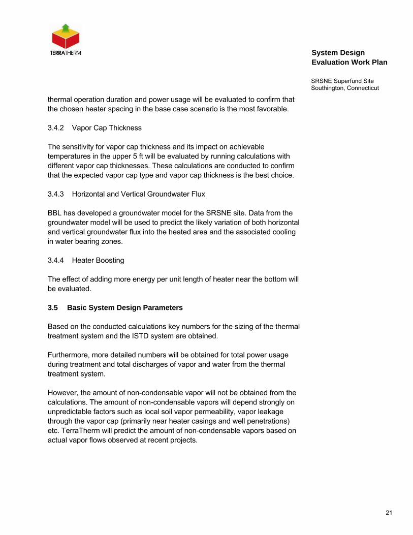
thermal operation duration and power usage will be evaluated to confirm that the chosen heater spacing in the base case scenario is the most favorable.
3.4.2 Vapor Cap Thickness
The sensitivity for vapor cap thickness and its impact on achievable temperatures in the upper 5 ft will be evaluated by running calculations with different vapor cap thicknesses. These calculations are conducted to confirm that the expected vapor cap type and vapor cap thickness is the best choice.
3.4.3 Horizontal and Vertical Groundwater Flux
BBL has developed a groundwater model for the SRSNE site. Data from the groundwater model will be used to predict the likely variation of both horizontal and vertical groundwater flux into the heated area and the associated cooling in water bearing zones.
3.4.4 Heater Boosting
The effect of adding more energy per unit length of heater near the bottom will be evaluated.
3.5 Basic System Design Parameters
Based on the conducted calculations key numbers for the sizing of the thermal treatment system and the ISTD system are obtained.
Furthermore, more detailed numbers will be obtained for total power usage during treatment and total discharges of vapor and water from the thermal treatment system.
However, the amount of non-condensable vapor will not be obtained from the calculations. The amount of non-condensable vapors will depend strongly on unpredictable factors such as local soil vapor permeability, vapor leakage through the vapor cap (primarily near heater casings and well penetrations) etc. TerraTherm will predict the amount of non-condensable vapors based on actual vapor flows observed at recent projects.
22
System Design Evaluation Work Plan
SRSNE Superfund Site Southington, Connecticut
Specific output of the calculations will be the following numbers:
• Size of ISTD power supply
• Vapor extraction rate
• Non-condensable vapor rate
• Condensable vapor (steam) rate
• Liquid extraction rate
• Condensed liquid rate
• Water treatment rate
• Heat exchanger sizing, vapor
• Heat exchanger sizing, water
The output key numbers will be the design basis for selection of appropriate equipment for the treatment system in the 30% Conceptual Design phase.
3.6 Reporting
Upon completion of the water and energy balance calculations and following the sensitivity analysis a report will be prepared describing the conducted calculations. The report will describe the calculation protocols and present the results of the study including possible minor ramifications for the full-scale ISTD treatment and will serve as the base for the conceptual ISTD design at the SRSNE Site.
The expected figures and tables included in the report are shown below.
Treatment Area and Target Depth Interval
Definition of Layers in the Calculations
Starting Parameters in Calculations at Time Zero
23
System Design Evaluation Work Plan
SRSNE Superfund Site Southington, Connecticut
Mass Balance Principles for Water
Mass Balance Principles for Energy
Energy Balance Schematic
Average Temperature for TTZ Layers During Operation
Average Saturation for TTZ Layers During Operation
Energy Balances for TTZ Layers
Overall Site Energy Balance
Sensitivity for Heater Spacing
Sensitivity for Vapor Cap
Sensitivity for Groundwater Flux
Sensitivity for Boosted Heaters
Design basis
The mentioned figures and tables are subject to change depending of the actual results from the water and energy balance calculations.
The numerical simulation report will be submitted with the Concept Design package as an attachment.