Erection of High Voltage direct Current (HVDC) converter ...

© ABB Group February 3, 2012 | Slide 1
System aspects on insulation levels for HVDC converter stations
Ulf Radbrandt, 2011-10-31
© ABB Group February 3, 2012 | Slide 2
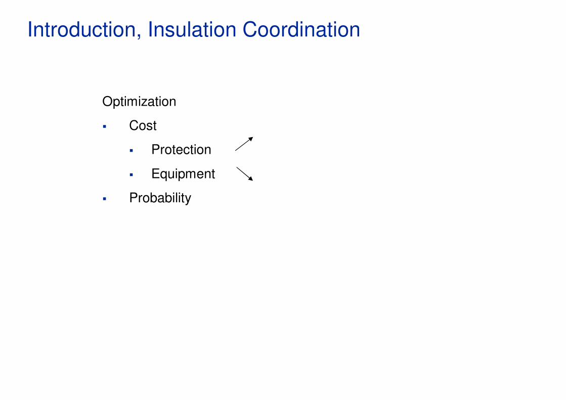
Introduction, Insulation Coordination
Optimization
� Cost
� Protection
� Equipment
� Probability

© ABB Group February 3, 2012 | Slide 3
Type of stresses
� Continuous AC - Normal operation- clean conditions
- contamination
- other
� Temporary overvoltage
� Abnormal system conditions
� Switching overvoltage
� System switching operations (lines, loads and equipment)
� Lightning overvoltage
� Lightning flashes to and around lines
� Dry
� Rain
� Snow & Ice
� Birds…
� Fires
� Vegetation

© ABB Group February 3, 2012 | Slide 4
Strength and Stress

© ABB Group February 3, 2012 | Slide 5
Strength and Stress

© ABB Group February 3, 2012 | Slide 6
Principles of insulation coordination
Primary objective is:
� Establish maximum steady state, temporary and transientovervoltages on equipment
� Select
� insulation strength and characteristics of equipment and protective devices
To ensure a safe, economic and reliable installation.
© ABB Group February 3, 2012 | Slide 7
Insulation coordination Important parameters
� Minimum Short Circuit Capacity,
� pre and post fault
� X/R
� X1/X0
� AC fault clearing times
� Auto-reclosing? Times?
� Maximum system voltage
� Arresters in the surrounding a.c. network characteristics
� DC and electrode line data
� Insulation margins

© ABB Group February 3, 2012 | Slide 8
Voltage profiles - Arrester scheme

© ABB Group February 3, 2012 | Slide 9
Voltages - Establish operating voltages

© ABB Group February 3, 2012 | Slide 10
Valve voltages
CCOV=π/3*Udi0absmax

© ABB Group February 3, 2012 | Slide 11
Surge Arresters – Polymeric type
PEXLIM P arrester

© ABB Group February 3, 2012 | Slide 12
Surge Arresters - Valve hall arrester

© ABB Group February 3, 2012 | Slide 13
Surge Arresters
IcapIres
Continuous operating voltage (Uc)
Rated voltage (Ur)
Protection against switching overvoltages
Protection against lightning overvoltages
Ires, resistive current
Effect of increased block temperature on Ires
Icap, capacitive current (no influence from temperature)
Current (Ampere)
Voltage (p.u.)Min protection levels in kV (peak)according IEC60099-4
Region 1 Region 2 Region 3
2.3
2.0
1.0 x √2
0.8 x √2
10-5 10-3 102 103 104 Log scale

© ABB Group February 3, 2012 | Slide 14
Surge Arresters – Protective parameters
Urw
Overvoltage without
surge protection
Urw
Up
Protective
margin
Overvoltage with
surge arresters
Urw = Insulation level of equipment
Up = Protective level of the S.A.
© ABB Group February 3, 2012 | Slide 15
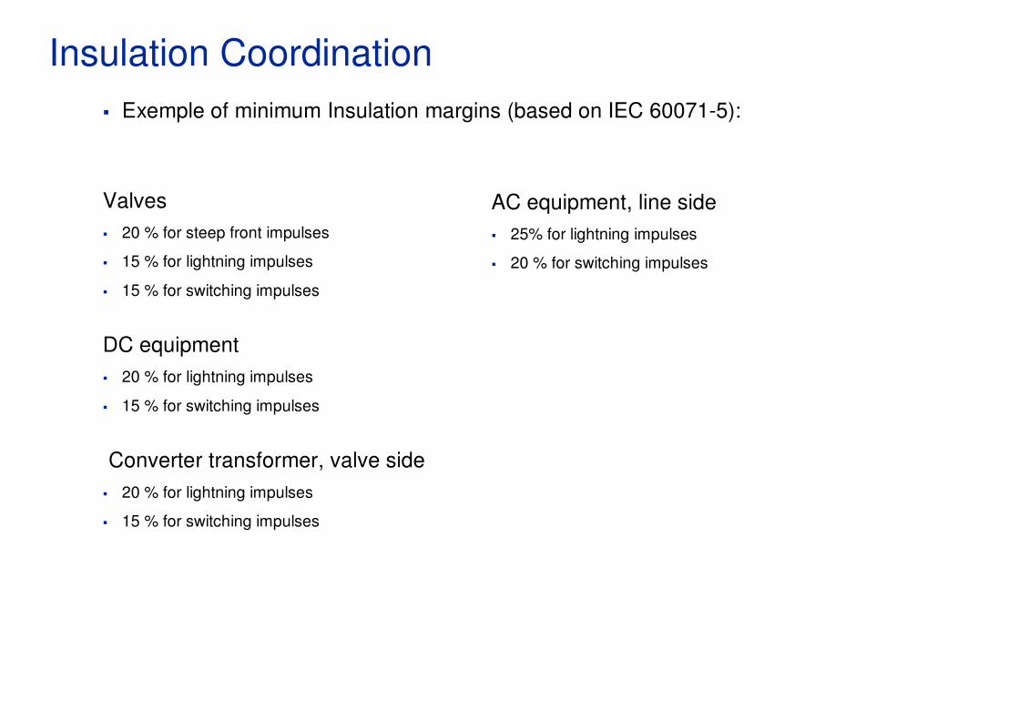
Insulation Coordination
� Exemple of minimum Insulation margins (based on IEC 60071-5):
Valves
� 20 % for steep front impulses
� 15 % for lightning impulses
� 15 % for switching impulses
DC equipment
� 20 % for lightning impulses
� 15 % for switching impulses
Converter transformer, valve side
� 20 % for lightning impulses
� 15 % for switching impulses
AC equipment, line side
� 25% for lightning impulses
� 20 % for switching impulses

© ABB Group February 3, 2012 | Slide 16
Factors affecting on surge arrester dimensioning
� Continuous operating voltage
� Climate (ambient temp., rain, sunshine)
� Mechanical stresses
� Temporary overvoltages, TOV
� Transient overvoltages
� Protection function
� Energy- and current strength
� Outer insulation
� High outer pollution
� Short circuit proof

© ABB Group February 3, 2012 | Slide 17
Energy dimensioning
� Current amplitude
� Duration
� Time between current pulses
� The number of pulses before cooling
� Total energy
© ABB Group February 3, 2012 | Slide 18
Surge Arresters – Difference between AC and DC
AC
•Much higher current through arresters (coordinating
current) for lightning than for switching overvoltages. That
leads to higher BIL than SIL
•The same maximum operating voltage in both ends of a
transmission line
DC
�About the same current through arresters (coordinatingcurrent) for lightning as for switching overvoltages. That leads to about the same BIL as SIL
�Lower maximum operating voltage in the receiving end of
a transmission line

© ABB Group February 3, 2012 | Slide 19
Converter Configuration for Xiangjiaba – Shanghai
DC
Filte
r
DC Neutral
DC Pole 800kV
ElectrodeLine

© ABB Group February 3, 2012 | Slide 20
Converter Configuration for North East - Agra
DC
Filte
r
DC Neutral
DC Pole 800kV
ElectrodeLine

© ABB Group February 3, 2012 | Slide 21
Transformer voltage characteristics – Steady State
Transformer voltages North East - Agra
-200
-100
0
100
200
300
400
500
600
700
800
900
1000
0 5 10 15 20
t [ms]
u [
kV
] tfo Y
tfo D
Transformer voltages Xiangjiaba – Shanghai
-200
-100
0
100
200
300
400
500
600
700
800
900
1000
0 5 10 15 20
t [ms]
u [
kV
]
tfo HV Y
tfo HV D
tfo LV Y
tfo LV D

© ABB Group February 3, 2012 | Slide 22
Transformer voltage characteristics – Transient
Arresters V135 C4 S1
0.000 0.025 0.050 0.075 0.100 0.001 0.099 0.097
-300
-200
-100
0
100
200
300
400
(kV
)
-0.075
-190.975
-190.900
Min -221.920
Max 377.457
UV1_4S1 UV3_4S1 UV5_4S1
-0.50
0.00
0.50
1.00
1.50
2.00
2.50
3.00
(kA
)
-0.000
-0.000
-0.000
Min -0.000
Max 2.654
IV1_4S1 IV3_4S1 IV5_4S1
0.0
1.0k
2.0k
3.0k
4.0k
5.0k
6.0k
7.0k
(kJ)
0.0007k
6.9177k
6.9170k
Min 0.0007k
Max 6.9177k
EV1_4S1 EV3_4S1 EV5_4S1
© ABB Group February 3, 2012 | Slide 23
Pros and cons with standard insulation levels for HVDCPros:
� Manufacturers can standardize their product portfolios
� Utilities can have the same equipment for several converter stations (same voltage level)
� Increased insulation margins for e.g. transformers and bushings because thyristor valves will
be optimized anyway (minimized insulation levels)
� Less need for thorough calculations/simulations?
Cons:
� Standard levels will mean higher levels (due to e.g. different insulation margins by different
utilities and different minimum short circuit capacity) which will give higher cost for equipment
� Higher insulation levels will limit the number of possible test institutes
� Higher insulation levels for transformers will lead to increased difficulties for transport
� Higher insulation levels for transformers will lead to increased amount for oil
� Higher insulation levels for transformer bushings will lead to increased size of valve halls
� Correction factors for external insulation might require selection of the next standard level
� Higher insulation levels for transformers might lead to higher commutation reactance which will
lead to increased number of thyristors and increased need for reactive power compensation

© ABB Group February 3, 2012 | Slide 24
Ongoing work within IEC
Extract from IEC TS 60071-5, Insulation co-ordination – Part 5 HVDC:
“Selection of standard withstand voltages for a.c. side equipment only. The present step is skipped for equipment on d.c. side because there are no standardized withstand voltage levels for such equipment
For equipment on the d.c. side, specified insulation levels are rounded up to convenient practical values”
Ongoing work for the revision of IEC 60071-5The work is going in the direction to even more emphasize the principle with tailor made insulation coordination and insulation margins instead of standard
insulation levels within the converterThe following line is added in the new draft under Clause 6.1 Essential differences between a.c. and d.c. systems:“• there exist no standard insulation levels in the case of d.c. systems“
The following is added in the new draft under Clause 12 Clearances in air:
�“The clearances in d.c. applications are based on insulation levels of equipment which are determined to provide the appropriate margin over the protective level of the arresters rather than on standard equipment levels.“