Voltage Source Converter Solution HVDC - IEEE PES … … · Voltage Source Converter Solution HVDC...
27
© Siemens Energy Inc 2013 HVDC PLUS Voltage Source Converter Solution HVDC Technology, Benefits, Applications
Transcript of Voltage Source Converter Solution HVDC - IEEE PES … … · Voltage Source Converter Solution HVDC...

© Siemens Energy Inc 2013
HVDC PLUS Voltage Source Converter Solution HVDCTechnology, Benefits, Applications

2 Nov 2013 Energy Sector / Transmission SolutionsE T TS 2 HVDC© Siemens Energy Inc 2013
Advantages over HVDC Classic
Large reactive power consumption (50-60% of active power flow) at both rectifier and inverter ends
Extensive filtering requirements due to low order harmonics
Large footprint
Dependence on strong AC systems
Power reversal involves voltage polarity reversal
Commutation failure

3 Nov 2013 Energy Sector / Transmission SolutionsE T TS 2 HVDC© Siemens Energy Inc 2013
HVDC PLUSThe Evolution of HVDC PLUS and VSC Technology
Power Electronic Devices GTO /IGCT IGBT in PP IGBT Module
Topology of VSC Two-Level Three-Level Multilevel

4 Nov 2013 Energy Sector / Transmission SolutionsE T TS 2 HVDC© Siemens Energy Inc 2013
HVDC PLUS Modular Multilevel Converter - MMC
Modular Multilevel Converter
+Udc/2
-Udc/2
Ud
Uac
+
+
+
+
+
+
+
+
+
+
+
+
+
+
+
+
+
+
+
+
+
+
+
+
Udc
Low level of harmonics and HF noise
Low switching losses
Modular arrangement with identical two-terminal power modules
5 Nov 2013 Energy Sector / Transmission SolutionsE T TS 2 HVDC© Siemens Energy Inc 2013
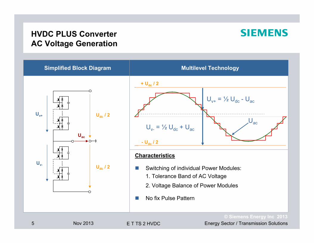
HVDC PLUS ConverterAC Voltage Generation
Simplified Block Diagram
Udc / 2
Uac
Udc / 2Uv+
Uv-
Multilevel Technology
Uv+ = ½ Udc - Uac
Uv- = ½ Udc + Uac
+ Udc / 2
- Udc / 2
Uac
Characteristics
Switching of individual Power Modules:1. Tolerance Band of AC Voltage
2. Voltage Balance of Power Modules
No fix Pulse Pattern

6 Nov 2013 Energy Sector / Transmission SolutionsE T TS 2 HVDC© Siemens Energy Inc 2013
HVDC PLUSGeneral Features of VSC Technology
Additional Features and Benefits of HVDC PLUS
Grid Access of weak AC Networks
Independent Control of Active and Reactive power
Supply of passive Networks and Black Start Capability
High dynamic Performance
Low Space Requirements

7 Nov 2013 Energy Sector / Transmission SolutionsE T TS 2 HVDC© Siemens Energy Inc 2013
States of Submodules
Energization Capacitor On Capacitor Off(converter blocked)
(charging) (charging)
(discharging)

8 Nov 2013 Energy Sector / Transmission SolutionsE T TS 2 HVDC© Siemens Energy Inc 2013
MMC – perfect Voltage Generation
VConv.
- Vd /2
0
+Vd /2
AC and DC Voltages controlled by Converter Module Voltages:
VAC

9 Nov 2013 Energy Sector / Transmission SolutionsE T TS 2 HVDC© Siemens Energy Inc 2013
=
~
=
=
~
=
=
~
=
n
2
1
1
2
n
Power Electronics Module - Redundancy
Phase Unit =Converter Towers + Reactors
PLUSCONTROL
Submodule
High-Speed Bypass Switch
Individual Failureof Submodule
10 Nov 2013 Energy Sector / Transmission SolutionsE T TS 2 HVDC© Siemens Energy Inc 2013
PLOTS : Graphs
1.000 1.010 1.020
-250 -200 -150 -100 -50
0 50
100 150 200 250
U [k
V]
+Ud -Ud US1 US2 US3
-2.00
-1.50
-1.00
-0.50
0.00
0.50
1.00
1.50
2.00
I [kA
]
is1 is2 is3
-1.50
-1.25
-1.00
-0.75
-0.50
-0.25
0.00
0.25
0.50
0.75
I [kA
]
i1p i2p i3p i1n i2n i3n
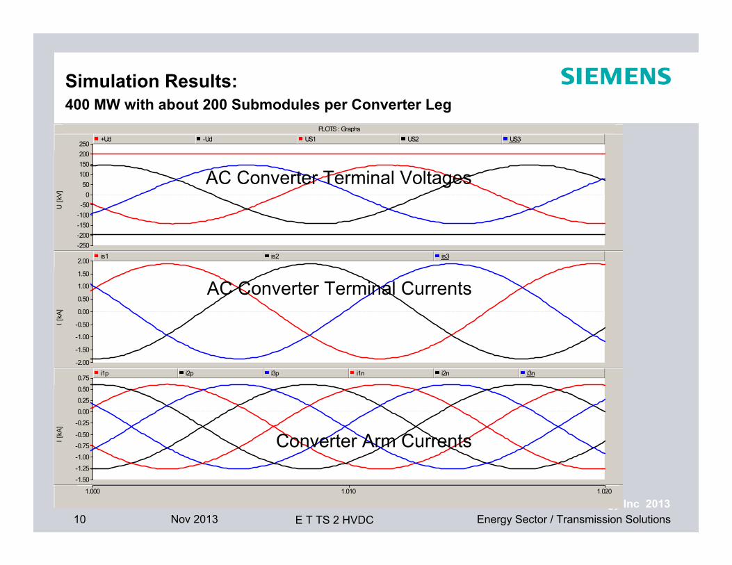
Simulation Results: 400 MW with about 200 Submodules per Converter Leg
AC Converter Terminal Voltages
AC Converter Terminal Currents
Converter Arm Currents

11 Nov 2013 Energy Sector / Transmission SolutionsE T TS 2 HVDC© Siemens Energy Inc 2013
HVDC PLUS Monopolar Configuration – Overview
tertiary winding
conventional AC transformers
star point reactor
tertiary winding
conventional AC transformers
star point reactor
12 Nov 2013 Energy Sector / Transmission SolutionsE T TS 2 HVDC© Siemens Energy Inc 2013
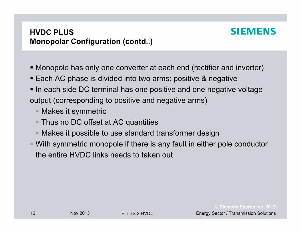
HVDC PLUS Monopolar Configuration (contd..)
Monopole has only one converter at each end (rectifier and inverter) Each AC phase is divided into two arms: positive & negative In each side DC terminal has one positive and one negative voltage output (corresponding to positive and negative arms) Makes it symmetric Thus no DC offset at AC quantities Makes it possible to use standard transformer design With symmetric monopole if there is any fault in either pole conductor
the entire HVDC links needs to taken out

13 Nov 2013 Energy Sector / Transmission SolutionsE T TS 2 HVDC© Siemens Energy Inc 2013
Basic Controls
5 possible control variables (reference set points)
1. Active power (Pref)2. DC link voltage (Vdc)3. AC side reactive power (Qref)4. AC side voltage magnitude (Vac-ref)5. AC side voltage phase angle (ac-ref)
Two variables can be controlled at each end but NOT in any combination
DC link voltage is controlled at one end
Balances in-flow and out-flow of active power at that end
Other end controls active power by setting either Pref or Vac-ref and ac-ref (e.g. offshore side converter for wind farm connections)
Qref or Vac-ref can be controlled independently at either end

14 Nov 2013 Energy Sector / Transmission SolutionsE T TS 2 HVDC© Siemens Energy Inc 2013
Decoupled Control
• Synchronously rotating d-q frame of reference is used to translate the sinusoidal set point tracking problem into equivalent DC set point tracking
• Inner loop current control is used to protect the IGBTs from over current
• Proper choice of d-q frame can decouple the control loops

15 Nov 2013 Energy Sector / Transmission SolutionsE T TS 2 HVDC© Siemens Energy Inc 2013
Control and Protection System Hierarchy Win-TDC with PLUSCONTROL
I/O Unit
Measuring
I/O Unit
CCSPLUSCONTROL
MMS nMMS 1
Remote HMISCADA InterfaceLocal HMI SIMATIC WinCC
I/O Level
Operator Level
Switchgear and Auxiliaries Voltages and Currents Converter – Power Modules
RCI
SIMATIC TDC
C&P Level
16 Nov 2013 Energy Sector / Transmission SolutionsE T TS 2 HVDC© Siemens Energy Inc 2013
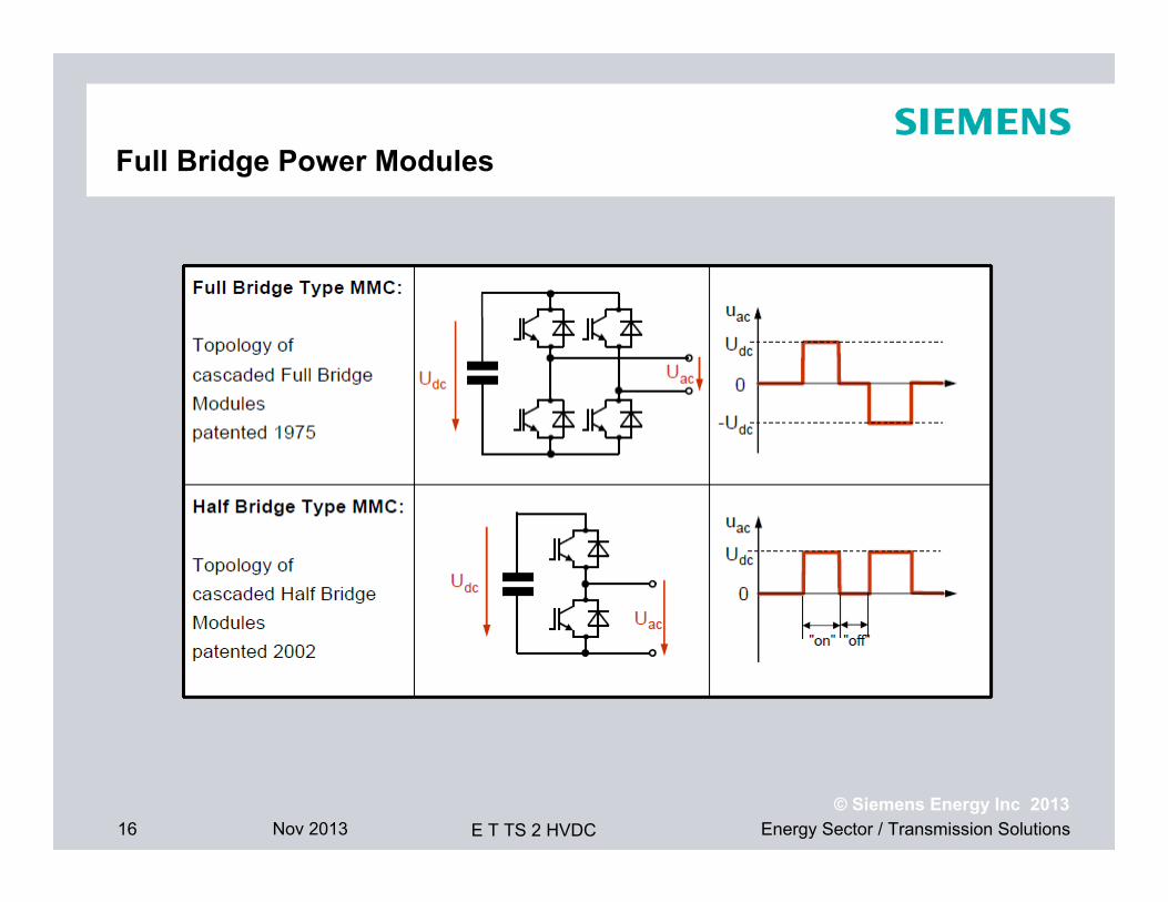
Full Bridge Power Modules

17 Nov 2013 Energy Sector / Transmission SolutionsE T TS 2 HVDC© Siemens Energy Inc 2013
Full BridgeAC Voltage is independent of DC Voltage
18 Nov 2013 Energy Sector / Transmission SolutionsE T TS 2 HVDC© Siemens Energy Inc 2013
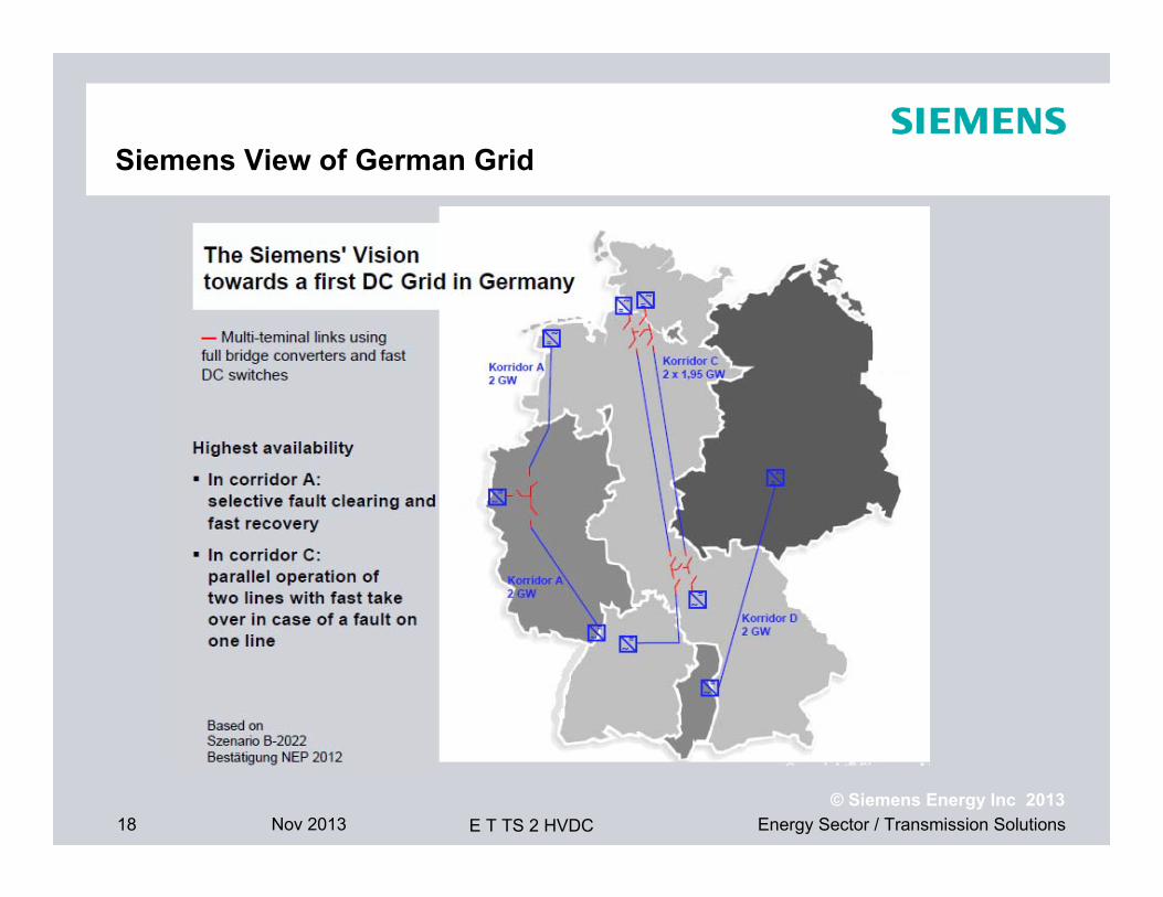
Siemens View of German Grid

20 Nov 2013 Energy Sector / Transmission SolutionsE T TS 2 HVDC© Siemens Energy Inc 2013
HVDC PLUS – Trans Bay Cable ProjectOverview
Customer Trans Bay Cable LLCProject Name Trans Bay Cable Project
LocationPittsburg, CASan Francisco, CA
Power Rating 400 MWType of Plant HVDC PLUSVoltage Levels ± 200 kV DC
230 kV/138 kV AC, 60 Hz
Semiconductors IGBTCable Supplier PrysmianCable Voltage ± 200 kVCable Type XLPEMax. Depth 50 mCable Distance 85 km Submarine Cable

21 Nov 2013 Energy Sector / Transmission SolutionsE T TS 2 HVDC© Siemens Energy Inc 2013
HVDC PLUS – Trans Bay Cable Project World’s first MMC-VSC Technology in Commercial Operation
22 Nov 2013 Energy Sector / Transmission SolutionsE T TS 2 HVDC© Siemens Energy Inc 2013
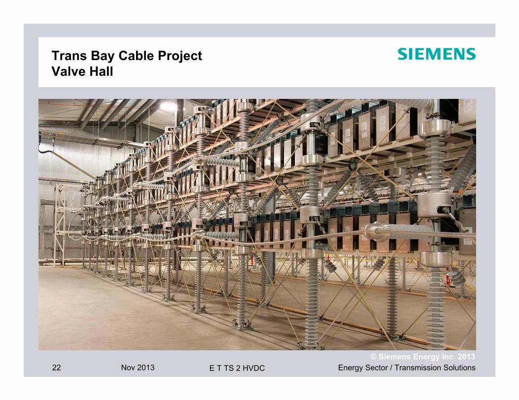
Trans Bay Cable Project Valve Hall
23 Nov 2013 Energy Sector / Transmission SolutionsE T TS 2 HVDC© Siemens Energy Inc 2013
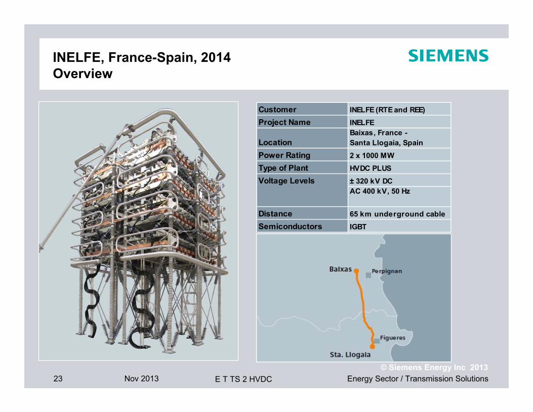
Customer INELFE (RTE and REE)Project Name INELFE
LocationBaixas, France - Santa Llogaia, Spain
Power Rating 2 x 1000 MWType of Plant HVDC PLUSVoltage Levels ± 320 kV DC
AC 400 kV, 50 Hz
Distance 65 km underground cableSemiconductors IGBT
INELFE, France-Spain, 2014Overview

24 Nov 2013 Energy Sector / Transmission SolutionsE T TS 2 HVDC© Siemens Energy Inc 2013
HVDC PLUSINELFE Converter Station Valve Hall
25 Nov 2013 Energy Sector / Transmission SolutionsE T TS 2 HVDC© Siemens Energy Inc 2013
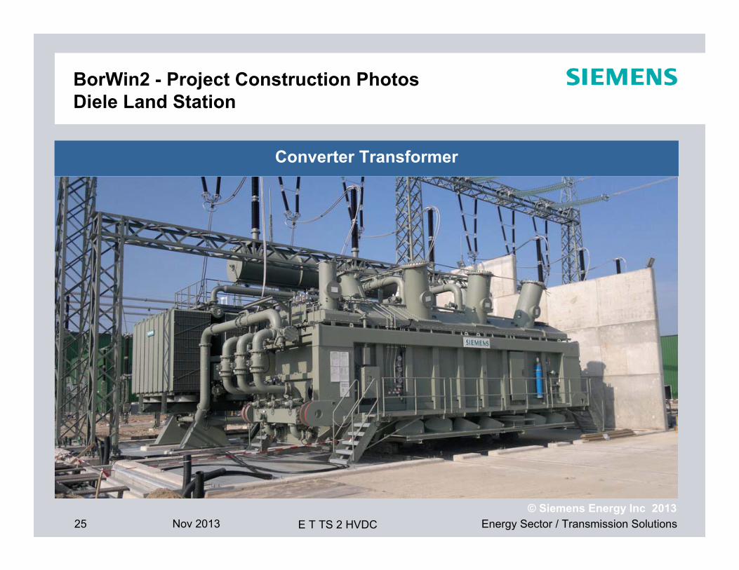
BorWin2 - Project Construction Photos Diele Land Station
Converter Transformer

26 Nov 2013 Energy Sector / Transmission SolutionsE T TS 2 HVDC© Siemens Energy Inc 2013
BorWin2 - Project Construction PhotosDiele Land Station
Works go on in the Converter Hall – May, 2012 (13 months after mobilisation)

27 Nov 2013 Energy Sector / Transmission SolutionsE T TS 2 HVDC© Siemens Energy Inc 2013
BorWin2 - Project Construction Photos Offshore Platform (Construction Site: Nordic Yard’s Dock, Wismar)
Works go on in the Converter Hall – May, 2012 (13 months after mobilisation)
Top Side Temporarily Towed Out of the Dock for the Swap of Dock Position with the SylWin Barge
28 Nov 2013 Energy Sector / Transmission SolutionsE T TS 2 HVDC© Siemens Energy Inc 2013
Questions?