SYNTHESIS AND CHARACTERIZATION OF PMMA-BASED POLYMER...
31
SYNTHESIS AND CHARACTERIZATION OF PMMA-BASED POLYMER GEL ELECTROLYTE Thesis Submitted for the Award of Degree of M.Sc. in Physics By PRIYADARSHINI PADHI 411PH2105 Under the Guidance of Dr. DILLIP KUMAR PRADHAN & Dr. SIDHARTHA JENA Department of Physics National Institute of Technology Rourkela-769008 Odisha, India
Transcript of SYNTHESIS AND CHARACTERIZATION OF PMMA-BASED POLYMER...
SYNTHESIS AND CHARACTERIZATION OF
PMMA-BASED POLYMER GEL ELECTROLYTE
Thesis Submitted for the Award of Degree of
M.Sc. in Physics
By
PRIYADARSHINI PADHI
411PH2105
Under the Guidance of
Dr. DILLIP KUMAR PRADHAN
&
Dr. SIDHARTHA JENA
Department of Physics
National Institute of Technology
Rourkela-769008
Odisha, India
Department of Physics
National Institute of Technology Rourkela
Rourkela, Odisha, India -769008
DECLARATION
I hereby declare that the work carried out in this thesis is entirely original. It was carried out
by me along with Miss Ranjeeta Giri at Department of Physics, National Institute of
Technology, Rourkela. I further declare that to the best of my knowledge the carried out
experimental work has not formed the basis for the award of any degree, diploma, or similar
title of any university or institution.
________________________
Priyadarshini Padhi
Roll Number: 411PH2105
Department of Physics
National Institute of Technology
Rourkela, 769008
Date:
Place: Rourkela

Department of Physics
National Institute of Technology Rourkela
Rourkela, Odisha, India -769008
CERTIFICATE
This is to certify that the thesis entitled “SYNTHESIS AND CHARACTERIZATION OF
PMMA-BASED POLYMER GEL ELECTROLYTE” being submitted by Priyadarshini
Padhi in partial fulfilment of the requirements for the award of the degree of Master of
Science in Physics at National Institute of Technology, Rourkela is an authentic experimental
work carried out by her under our supervision. To the best of our knowledge, the
experimental matter embodied in the thesis has not been submitted to any other
University/Institute for the award of any degree or diploma.
Date:
Place: Rourkela
Sidhartha Jena
Associate Professor
Department of Physics
National Institute of Technology
Rourkela, 769008
Dillip Kumar Pradhan
Assistant Professor
Department of Physics
National Institute of Technology
Rourkela, 769008

ACKNOWLEDGEMENT
I heartily express my deepest sense of gratitude to my supervisors
Dr. Dillip Kumar Pradhan and Dr. Sidhartha Jena for allowing and initiating
me to work in the field of “Synthesis and Characterization of PMMA based
polymer gel electrolyte” under their guidance. Their great interest,
encouragement and guidance had made my work fruitful. I extend my sincere
thanks to them for their invaluable suggestions and help throughout my
dissertation work.
I express my special thanks to Mr Tapabrata Dam, for his help in my
experimental works and guidance throughout my project. I would also like to
thank Mr Satya Narayan Tripathy and Miss Santripti Khandai for their valuable
views throughout my research project during the year.
I would also like to thank all the staff members and students of the department
for their kind help and co – operation and in particular to my project partner
Miss Ranjeeta Giri.
My hearty thanks to my parents for their blessings, inspiration and moral
support.
Date: (Priyadarshini Padhi)

ABSTRACT
PMMA based Polymer Gel Electrolytes have been prepared with different concentrations of
salt (NaI) by gelation method. This study has been carried out to understand the effect of salt
concentration on conductivity of polymer gel electrolyte. The prepared samples are
characterized by XRD, optical microscopy, FTIR and Dielectric spectroscopy. The XRD
studies revealed that the prepared polymer gel electrolyte samples are semi-crystalline in
nature. Optical Microscopy study confirmed the results obtained from the XRD analysis.
FTIR Spectroscopy study indicated the bands present in the samples were not affected for
different salt concentration, which indicates that the polymer does not participate in the
complexation process. The dielectric and electrical properties of the material were studied by
the dielectric spectroscopic technique in a wide frequency range at room temperature. The d.
c. conductivity of samples was calculated using complex impedance plots.

CONTENTS
Chapter 1: Introduction 1-8
1.1 Electrolyte 1
1.2 Classification of Electrolyte 1
1.3 Liquid Electrolyte 1
1.4 Solid Electrolyte 1
1.5 Advantages of Solid Electrolyte 2
1.6 Classification of Solid Electrolyte 2
1.7 Polymer Gel Electrolyte 5
1.8 Literature Survey 5
1.9 Objectives 8
Chapter-2: Sample Preparation and Characterization Technique 9-14
2.1 Methods of Sample Preparation 9
2.2 Materials Used 10
2.3 Procedure of Sample Preparation 11
2.4 Flow Chart 12
2.5 Characterisation Techniques Used 12
Chapter-3: Results and Discussions 15-22
3.1 XRD 15
3.2 Optical Microscopy 17
3.3 FTIR 18
3.4 Dielectric study 19
Chapter-4: Conclusions 23
References 24-25

1
CHAPTER- I
INTRODUCTION
1.1 ELECTROLYTE:
An electrolyte is any substance that has free ions. For example dissociated salt into its constituent
ions in a solution is an electrolyte. These ions act as an electrically conductive medium, which
helps in conduction of electricity [1]. When KI, is added to water, the salt dissociates into its
component ions.
Generally electrolyte is used in fuel cells or electrochemical cells such as battery for conduction
of electricity and energy storage.
1.2 CLASSIFICATION OF ELECTROLYTE
Based on the physical state of electrolytes can be classified into two categories such as:
(i) Liquid electrolyte and (ii) Solid electrolyte
1.3 LIQUID ELECTROLYTE
When salt is dissolved in liquid solvent it forms liquid electrolyte. For example when KI is
dissolves in water forms liquid electrolyte. Liquid electrolytes have very good ion conductivity
of the order of 10-2
[2]. Although in the present era, liquid electrolyte is used in many
conventional devices, there are many inherent disadvantages of using liquid electrolyte. These
are:
1. Narrow range of operating temperature.
2. Leakage of harmful liquids or grassing.
3. Corrosion reaction between electrode and electrolyte.
4. Low energy and power density.
5. Relatively short life time.
To overcome all the above disadvantage, the ideas of using solid electrolytes has been conceived
[3].
1.4 SOLID ELECTROLYTE
The ionic solids which have high conductivity at room temperature are known as solid
electrolyte. The conduction is due to the movement of ions through voids, or empty

2
crystallographic positions, in their crystal lattice structure. The cation or anion of the structure
must be free to move in the structure as charge carrier. They have ion conductivity of the order
of 10-6
[4].
There are some essential features of a solid electrolyte like [5]:
1. High ion conductivity of order 10-1
to 10-4
and low electron conductivity less
than 10-12
2. Low activation energy (Ea< 0.3 e V)
1.5 ADVANTAGES OF SOLID ELECTROLYTE
1. Longer life cycle than typical liquid electrolyte batteries
2. Broad range of temperature tolerance
3. Prevention from leakage of electrolyte
4. Reaction products are not inflammable.
Though solid electrolytes have many advantages over liquid electrolyte but conductivity in solid
electrolyte is less than the required value for device applications usually of the order
of .
1.6 CLASSIFICATION OF SOLID ELECTROLYTE
On the basis of microstructure and physical properties, solid electrolyte can be classified as the
following four types:
1. Framework crystalline materials
2. Amorphous – glassy electrolytes
3. Composite electrolytes
4. Polymer electrolytes
From the above four types Framework Crystalline materials is ordered and the other three phases
are disordered. While the glassy and polymer electrolytes are microscopically disordered the
composite electrolytes are macroscopically disordered [6].
1.6.1 FRAMEWORK CRYSTALLINE MATERIALS
Crystalline solid electrolytes are those which conduct H+, Li
+, Na
+, K
+, O
2- as well as numerous
divalent and trivalent cations. The bonding is generally due to ionic and covalent. The ion
conductivity occurs due to hopping mechanism from site to site along channel in crystal
structure. The number of sites available for the mobile ions is usually greater than the number of

3
mobile ions present. The mobile ions have high diffusion coefficient and are therefore ion
conductors. Examples of crystalline solid electrolytes are AgI, CuI etc [7].
1.6.2 AMORPHOUS GLASSY ELECTROLYTE
The amorphous glassy electrolytes are more advantageous than framework crystalline materials
because (i) their compositions can be changed, (ii) they have high ionic conductivity, (iii) there
are no grain boundaries and (iv) thin films can be formed from it. The glassy electrolyte usually
having the chemical composition, MX: M2O: AxOy. AxOy is the oxide, which can be B2O3, P2O5,
SiO2, MoO3 etc. M2O is the network modifier, which can be Ag2O, Li2O, Cu2O, Na2O etc. MX is
the dopant salt which can be silver halides, alkali halides, copper halides, etc. Most of the glassy
electrolytes are obtained by quenching from the liquid state, which results in a little variation of
atomic structure from the original liquid [8].
1.6.3 COMPOSITE ELECTROLYTE
Composite electrolyte is a class of solid electrolyte which has high ionic conductivity which
occurs through interfaces. It is a multi-phase solid system (generally two phase) where an inert
phase particle (second phase) is added to an ion conducting (first phase) host material to increase
the conductivity. The increased conductivity depends upon concentration and particle size of the
inert phase [9].
1.6.4 POLYMER ELECTROLYTE
In mid-1970, it was recognized by P. V. Wright and his co-worker that, potassium salt form
complexes with Poly(ethylene oxide) (PEO) and Poly(propylene oxide) (PPO) giving rise to the
solid polymer electrolyte [10]. But in late 1970, the technological applications of these materials
in various solid state electrochemical devices were realized. Solid polymer electrolytes are
formed by complexation of polar polymers like poly(ethylene oxide), poly(propylene oxide),
poly(ethylene glycol) etc. with ionic salts of mono-valent alkali metal or divalent transition metal
ammonium salts, having low lattice energy and bulky anionic salts. Polymer electrolytes have
the advantages over the solid crystalline and glassy electrolytes; because the solid crystalline and
glassy electrolytes are hard and brittle materials. However polymer electrolytes are true solids,
but at atomic level it is capable in providing liquid like degrees of freedom. It forms a bridge

4
between liquid electrolytes and solvent free ceramic or molten electrolyte. It has many
advantages over other solid electrolyte such as (i) ease of processing, (ii) good interfacial contact
with electrodes (iii) good flexibility, (iv) light weight and (v) free from leakage. They have good
mechanical properties, low electronic conductivity, high chemical, electrochemical and thermal
stabilities etc. Solid polymer electrolyte can be classified into following types:
1. Conventional Polymer Salt Complex
2. Plasticized Polymer Electrolyte
3. Composite Polymer Electrolyte
4. Polymer Gel Electrolyte
1.6.4.1 Conventional Polymer Salt Complex
Dry solid polymer electrolyte can be prepared by complexation of a salt in a polar polymer host
like PPO, PEO etc. and also known as polymer – salt complex. The observed ionic conductivity
of this polymer – salt complex is very low as compared to the desired value [11].
1.6.4.2 Plasticized Polymer Electrolyte
It can be prepared by adding a plasticizer, which is a low molecular weight and high dielectric
constant material to the conventional polymer salt complex. The introduction of a plasticizer
significantly improves the ionic conductivity as well as flexibility to the system, but the
mechanical strength decreases. Still the observed ionic conductivity is below the desired level
[12].
1.6.4.3 Polymer Gel Electrolyte
Polymer gel electrolyte can be prepared by adding non-conducting polymer to a liquid
electrolyte in a balanced ratio so that polymerization will produce a gel. The polymer is added to
give the mechanical support to the system. So at macroscopic level it behaves like a solid and
liquid like properties is observed at microscopic level [13].

5
1.6.4.4 Composite Polymer Electrolyte
Composite polymer electrolyte is prepared by adding small fraction of micro or nano-size
inorganic or organic filler particles with the conventional solid polymer electrolyte. It is
generally analogous to composite electrolyte. But due to the addition of fillers the electrical
conductivity and mechanical stability increases. However the observed ionic conductivity is still
below the desired level [14].
As my project work is on polymer gel electrolyte so a detailed description is given below.
1.7 POLYMER GEL ELECTROLYTE
Gel is a substance which has solid like cohesive property and liquid like diffusive property.
Polymer gel electrolytes are generally prepared by adding a high molecular weight non-
conducting polymer to a liquid electrolyte i.e., salt dissolved in polar solvent. Ethylene carbonate
(EC), propylene carbonate (PC), dimethyl formamide (DMF), diethyl carbonate (DEC), dimethyl
carbonate (DMC) etc. are generally used as solvent. The salt provides ion for conduction and it
should have low activation energy. The salt can be is usually of alkali metals. The macro-
molecular polymer provides the mechanical strength to the system. Polymers like
poly(acrylonitrile) (PAN), poly(methyl methacrylate) (PMMA), poly(vinylidene fluoride)
(PVDF) etc are generally used for preparation of gel electrolyte [15]. Solvents are usually of low
molecular weight; which increases the conductivity by providing a locally mobile co-ordination
environment for ion motion. Polymer gel electrolytes have high ionic conductivity as required
for device application such as lithium batteries, super-capacitors and electrochemical devices.
Although the ionic conductivity is observed to be up to the desired level, the electrochemical
stability and mechanical stability is barrier for device applications.
1.8 LITERATURE SURVEY
M. Deepa et. al. studied the ionic conductivity and viscosity of liquid and PMMA based gel
electrolyte. Liquid electrolytes comprising lithium salts (LiClO4, LiN(CF3SO2)) dissolved in
solvent PC and a binary mixture of PC and EC show conductivity of the order of 10-2
.
Gel electrolytes were synthesized by incorporation of PMMA up to 25 wt% in these liquid
electrolytes, which shows the conductivity value 10-3
S/cm with a very high macroscopic

6
viscosity. So they concluded that gel electrolytes can be visualized as highly viscous liquid
electrolytes encaged in a polymeric matrix and the polymer PMMA provides mechanical
stability to the gel [16].
Z. Osman et. al. prepared (PMMA based) polymer gel electrolyte using solvent casting
techniques from EC-PC mixed solvent and various concentration of LiBF4 salt. They observed
that the ionic conductivity of the samples increased with increase in salt concentrations and after
reaching the optimum value it decreases due to the saturation of the salt. The ionic conductivity
value found to be 2.24×10⁻³
at room temperature for 20 wt% of LiBF4 [17].
Hee-Tak Kim et. al. prepared a (PVC-PMMA) polymer blend electrolyte with different
plasticizers for Li ion battery. It was reported that the polymer blend electrolytes exhibited phase
– separated structure which consists of PVC – rich phase and an electrolyte – rich phase. At the
constant blend ratio of PVC/PMMA = 4/6, mechanical property and ion conductivity increases
[18].
X. Helan Flora et. al. prepared polymer blend electrolytes using solution casting technique. They
studied for various concentration of LiClO4 salt with the constant ratio of PAN and PMMA. The
maximum ionic conductivity was found for the polymer electrolyte containing PAN (75 wt %) –
PMMA (25 wt %) – LiClO4 (8 wt %) to be 0.56 x 10⁻⁵
at 303 K [19].
A. Manuel Stephan in his review paper reported the ion conductivity and morphology of polymer
gel electrolyte of five different polymer hosts. The ion conductivity of the polymer host increases
when plasticizer is added, whereas the ionic conductivity decrease with increase amount of
polymer in polymer gel electrolyte [20].
Jiri Vondrak et. al. prepared PMMA based polymer gels containing Li, Na, Mg, and Zn
perchlorates and PC as plasticizers. From the resistivity studies they conclude that the resistivity
of a gel with a smaller cation is higher than that of a gel containing a larger cation [21].

7
Y. H. Liao et. al. prepared a self-supported P(MMA-AN-VAc) based gel polymer electrolyte
containing LiPF6 as salt. It is found that, the above gel electrolytes have high thermal stability of
310 °C, good mechanical strength, electrochemically stability up to 5.6 V and conductivity of
3.48×10⁻³ at ambient temperature [22].
Hong-Ryun Jung et. al. synthesized PMMA/PVC blend membrane by electro – spinning method
using DMF as solvent. Among the PMMA/PVC – based gel polymer electrolyte, the electrolyte
comprising of 10wt% PMMA and 90wt% PVC has the highest ionic conductivity of value
7.8×10⁻³
[23].
S. N. Asmara et. al. prepared PMMA based magnesium ion gel polymer electrolyte using
EC:DEC (2:1) as solvent. The highest conductivity of 5.58×10⁻⁵
and electrochemical
stability up to 2.42 V was obtained for polymer/solvent in mass ratio 40/60. The highest
conducting gel polymer electrolyte has been used to fabricate an electric double layer capacitor
(EDLC) [24].
Hee-jin Rhoo et. al. prepared polymer gel electrolyte in solution casting technique by taking the
blend of PVC-PMMA as the host polymer, mixture of EC-PC as plasticizer and LiCF3SO3 as
salt. They studied the effect of the PMMA – PVC blend ratio and the plasticizer content on the
ionic conductions of the system. The mechanical property was improved by the incorporation of
PVC into the electrolyte system. But the ionic conductivity decreased with increasing the
PVC/PMMA ratio and increased with increasing the plasticizer content [25].
D. Saikia et. al. investigated the ion transportation in P(VDF-HFP)–PMMA–LiCF3SO3–
(PC+DEC) – SiO2 fumed composite gel polymer electrolyte system. SiO2 dried fumes were used
as fillers to get composite gel polymer electrolyte. Samples were prepared by solvent casting
technique with varying the solvent – filler ratio. Increase in ion conductivity was observed due to
addition of fillers. Highest ion conductivity of 1×10⁻³
at 303 K is observed for 20wt%
P(VDF-HFP), 10wt% PMMA, 10wt% LiCF3SO3, 56wt% (PC + DEC) and 4wt% SiO2 fumed
[26].

8
S. Rajendran et. al. prepared polymer electrolyte system containing PMMA as host polymer,
LiBF4 and LiAsF6 as salt, plasticizer DBP and inorganic filler ZrO2 powder. The prepared
samples were studied using FTIR and impedance spectroscopy. From the FTIR study they
observed that the complex formation in PMMA – LiBF4/LiAsF6 – DBP – ZrO2 and the complex
remains mainly in the amorphous phase. Impedance spectroscopy study showed the increase in
conductivity is due to the addition of ZrO2.The maximum values of conductivities obtained are
4.6×10⁻⁵
and 1.9×10⁻⁴
for samples with 10 weight ratio of ZrO2 to PMMA–
LiBF4/ LiAsF6 –DBP polymer electrolyte systems respectively at 304 K [27].
Xinping Hou et. al. prepared gel polymer electrolyte using solution casting technique by taking
PMMA and ABS polymer blend, EC/PC (1:1 by weight) andLiClO4. Dual – phase structure was
observed from the SEM and DSC analysis. They reported that the plasticizer – rich phase
provided a path for the ion transport and the ABS – rich phase acted as a mechanically
supportive matrix. The ionic conductivity of the electrolytes decreased with the increasing
ABS/PMMA ratio and increased with the increasing plasticizer content at 15% LiClO4 content.
Due to incorporation of ABS the desirable mechanical property had developed which was
confirmed from the stress – strain curves [28].
1.9 Objectives:
Based on the literature survey, the main objective of our work is as follows:
To prepare PMMA- based polymer gel electrolyte by taking different concentrations of
the salt with respect to the solvent.
To get information about the amount of crystalline and amorphous content in the
prepared polymer gel electrolyte samples, X- ray diffraction technique will be adopted.
To characterize the samples by optical microscopy, so as to analyze the surface
morphology of the samples.
To get the information about the bonds present in the sample, FTIR spectroscopy
characterization will be adopted.
To find out the detailed electrical properties of the polymer gel electrolytes, Complex
impedance/Dielectric Spectroscopy characterization techniques will be used.

9
CHAPTER-II
SAMPLE PREPARATION AND CHARACTERIZATION TECHNIQUE
2.1 METHODS OF SAMPLE PREPARATION:
There are different common methods to prepare different polymer electrolyte are available in
literature. Some of them are discussed below.
2.1.1 Solution Cast Technique:
It is a very common method for preparation of polymer gel electrolyte. In this method, suitable
amount of polymer is dissolved in a polar solvent, and then a required amount of salt is added to
it. The solutions obtained should be stirred for 10 to 12 hours using the magnetic stirrer, for
complexation of polymer host and salt. The polymer solution is then poured into a petridish and
then the free standing polymer electrolyte films will be formed through slow evaporation of the
solvent and followed by vacuum drying.
2.1.2Hot Press Technique:
In this process dry powder of polymer and salt is taken in a suitable ratio and is mixed
thoroughly by agate mortar. Then the mixture is heated above the melting point temperature of
the host polymer for sufficient time for polymer – salt complexation. The prepared soft lump is
then pressed between the cold metal blocks which give rise to a uniform polymer electrolyte
films. After heating and pressing, the sample is then slowly cooled to room temperature. It has
many advantages over solution cast technique such as it is a rapid process and it is least
expensive. Using this method dry and solvent free electrolyte can be prepared.
2.1.3 Gelation Method:
This is the common technique used generally for preparation of gel. In this method first the salt
will be added in the solvent and stirred up to complete dissolution of salt. Then the polymer is
added slowly and stirred for some time. Then the prepared solution is casted in petridish and left
for few hours for gelation.
In our sample preparation method we have used the gelation method to prepare the sample as it
is very easy and less expensive method.

10
To calculate the required amount of salt for preparation of the polymer gel electrolyte, we have
used the following formula [29]
Where And in my case active oxygen
2.2 MATERIALS USED
For preparation of polymer gel electrolyte, poly(methyl methacrylate) (PMMA), Propylene
Carbonate (PC), Ethylene Carbonate (EC) and NaI are used.
2.2.1 POLYMER: poly(methyl methacrylate) (PMMA)
PMMA is a high molecular weight polymer, which provides mechanical strength and flexibility
to the gel electrolyte. Melting point of PMMA is 160°C.
Fig.1 Structure of PMMA
2.2.2 SOLVENT:
Ethylene Carbonate (EC): EC is taken as the solvent. It donates active oxygen for complex
formation. EC has a molar mass of 88.06 g/mol and melting point of 34 – 37 °C. Molecular
formula of EC is C3H4O3.
Propylene Carbonate (PC): PC has molar mass 102.09 g/mol and melting point – 48.8 °C.
Molecular formula of PC is C4H6O3.

11
Fig. 2(a) Structure of Ethylene Carbonate Fig. 2(b) Structure of Propylene Carbonate
2.2.3 SALT: Sodium Iodide (NaI): NaI has molar mass 149.89 g/mol. It has low lattice energy
and bulky anion which helps in easy dissociation and there by facilitating the complexation.
2.3 PROCEDURE OF SAMPLE PREPARATION
3 ml of Propylene Carbonate (PC) was taken in a clean beaker and required amount of Ethylene
Carbonate (EC) was dissolved in it, to get a solvent of EC + PC in 1:1 molar ratio. The required
amount of salt i.e. Sodium Iodide (NaI) was weighed. The weighed NaI is added slowly to the
EC + PC solvent. It was then mixed thoroughly with a stirrer. Then a required amount of
polymer i.e. poly(methyl methacrylate) (PMMA) was weighed and mixed well with the already
prepared solution. It was continuously stirred till all the polymer taken got mixed with the salt
and solvent. The polymer and solvent were taken in 2:3 ratios. The same procedure was followed
to prepare different samples of gel by keeping the amount of PMMA constant and by changing
the concentration of salt. Then the prepared gels were spread on separate petridishes and left as
such for few days for gelation process.

12
2.4 FLOW CHART FOR GEL POLYMER ELECTROLYTE BY GELATION
METHOD
Fig. 3 Flow chart for preparation of polymer gel electrolytes.
2.5 CHARACTERISATION TECHNIQUES USED
The prepared gel polymer electrolytes are characterized by the following techniques
1. XRD
2. Optical Microscopy
3. FTIR Spectroscopy
4. Dielectric Spectroscopy
Prepared solution is poured in petridish and is left as such for few days for
the gelation process.
5ml of EC + PC in 1:1 ratio (solvent) was taken in a beaker.
Appropriate amount of salt i.e. Sodium Iodide (NaI) is weighed.
Both the salt and the solvent are mixed thoroughly in a beaker.
Appropriate amount of PMMA is weighed and added to solution to get
the desired gel.
By keeping the amount of PMMA constant and varying salt concentration
optimization of conductivity of gel is carried out.

13
2.5.1 X-Ray Diffraction (XRD)
X-Ray Diffraction technique is an analytical method used to study crystal structure, phase,
chemical composition and physical structure of materials or thin film.The X-ray diffraction
pattern of a pure substance is like the fingerprint of the substance.
This technique is based on Bragg’s law i.e
Fig 4. Schematic diagram of Bragg’s law
When the X – rays of wavelength of few Å is incident on the sample, having the same
interatomic distances in crystalline solids, the diffracted rays interact to produce constructive
interference. By observing the diffracted rays and by using Bragg’s law inter-atomic spacing (d)
can be calculated. The intensity pattern of the XRD spectra also enables us to calculate fraction
of amorphous content in a semi crystalline polymer.
2.5.2 Optical Microscopy
Optical Microscope is a type of microscope which uses visible light and a system of lenses to
magnify images of small samples. Basic optical microscopes can be very simple, although there
are many complex designs to improve resolution and sample contrast. The image of the optical
microscopy can be captured by normal light sensing camera or by CCD camera.
2.5.3 Dielectric Spectroscopy
It is a non-destructive technique used to study the electrical properties of material. By applying
sinusoidally varying alternating voltage to a sample the dielectric properties as a function of
frequency is recorded here. Dielectric properties like small molecule rotation in liquids, large
molecule reorientation in polymers, bulk conduction in solids and liquids and separation of
electrode effects, surface conduction and grain boundary change in porous materials and
14
interstitial ion effects in solids and gel electrolyte can be measured. In our case only the
impedance, phase capacitance, tangent loss parameters were measured.
2.5.4 FTIR Spectroscopy
Fourier transform infrared spectroscopy (FTIR)is an important technique for identification and
characterization of a substance. It is based on the absorption spectrum of sample for each
wavelength. A beam containing IR radiations of many frequencies is passed through a sample at
once, and measures how much of that beam is absorbed by the sample. The resulting spectrum
represents the molecular – absorption and transmission, creating a molecular finger print of the
sample. No two unique molecular structures produce the same infrared spectrum. This makes
infrared spectroscopy useful and unique for several types of analysis like identification of
unknown material, amount of component in a mixture etc.

15
CHAPTER-III
RESULTS AND DISCUSSIONS
3.1 XRD
10 20 30 40 50 60 70
O/Na=100
O/Na=80
O/Na=60
O/Na=40
In
ten
sity
(arb
. u
nit
s)
2Degree
O/Na= 20
Fig.5 XRD patterns of samples for different salt concentrations
The XRD studies carried out using a Philips X’pert X-Ray Diffractometer using Cu –
radiation (λ = 1.5405 Å) in the 2θ range of 10° - 70º at the scan speed of 2º per min at room
temperature. From the XRD data we observed a broad hump around 19º - 20 º. We can conclude
from the observations that the prepared polymer gel electrolyte samples are semi-crystalline in
nature. From Fig.5, it is observed that the hump shifts slightly towards left with increase in O/Na
concentration.
Using Bragg’s law i.e. the inter-planar spacing for different samples are
calculated by taking , = wavelength of X – ray (1.5405 Å), = angle of diffraction.
The inter – chain separation is calculated by using the formula:
(
) (
)

16
Where R is the inter chain length, λ is wavelength of X-ray, θ is the scattering angle.
Table 3.1 Inter-chain separation and Inter-planar spacing of polymer gel electrolytes:
O/Na 2θ (degree) Inter chain separation
R=(7/2π)×( λ/2sinθ) (Å)
Inter planar spacing
d=λ/2sinθ (Å)
20 20.48 4.8279 4.3313
40 20.34 4.8609 4.3609
60 20.1 4.9183 4.4124
80 19.9 4.9647 4.4563
100 19.68 5.0196 4.5056
With the increase of O/Na ratio (i.e., with decrease in salt concentration) the inter chain
separation and inter planar spacing increases gradually.

17
3.2 OPTICAL MICROSCOPY
Fig. 6(a), 6(b), 6(c), 6(d), 6(e) optical microscopy image for O/Na=20, 40, 60, 80 & 100 respectively
6(a) 6(b)
6(d) 6(c)
6(e)

18
The optical microscopy has been carried out using Olympus BX51 microscope with various
magnifications at room temperature. Optical microscopy shows the presence of distinct
spherulites when the selected magnification is 50X. The region between spherulite boundaries is
amorphous in nature and we can conclude that polymer gel electrolytes are semicrystaline in
nature having amorphous boundary between the crystalline spherulite. This is supporting the
XRD result.
3.3 FTIR SPECTROSCOPY
FTIR Spectra of the prepared samples were recorded from range of wavenumber 400 – 3000
with the help of Thermo Nicolet, NEXUS – 870 Infrared spectrometer at room
temperature.
Fig. 7 FTIR spectra for O/Na= 40, 60, 80 & 100
The Fig. 7 shows the FTIR spectroscopy plot of Transmittance Vs Wavenumber for different
O/Na concentrations. All the FTIR spectra for different O/Na ratio are alike. All the bands
present have been assigned in Table 3.2. We can conclude that the polymer is not participating in
any complexation process in the preparation of polymer gel electrolyte.
500 1000 1500 2000 2500
Tra
ns
mit
tan
ce
wavenumber (cm-1)
O/Na=40
O/Na=60
O/Na=80
O/Na=100
19
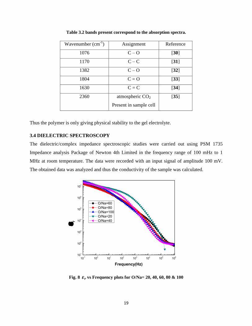
Table 3.2 bands present correspond to the absorption spectra.
Wavenumber (cm-1
) Assignment Reference
1076 C – O [30]
1170 C – C [31]
1382 C – O [32]
1804 C = O [33]
1630 C = C [34]
2360 atmospheric CO2
Present in sample cell
[35]
Thus the polymer is only giving physical stability to the gel electrolyte.
3.4 DIELECTRIC SPECTROSCOPY
The dielectric/complex impedance spectroscopic studies were carried out using PSM 1735
Impedance analysis Package of Newton 4th Limited in the frequency range of 100 mHz to 1
MHz at room temperature. The data were recorded with an input signal of amplitude 100 mV.
The obtained data was analyzed and thus the conductivity of the sample was calculated.
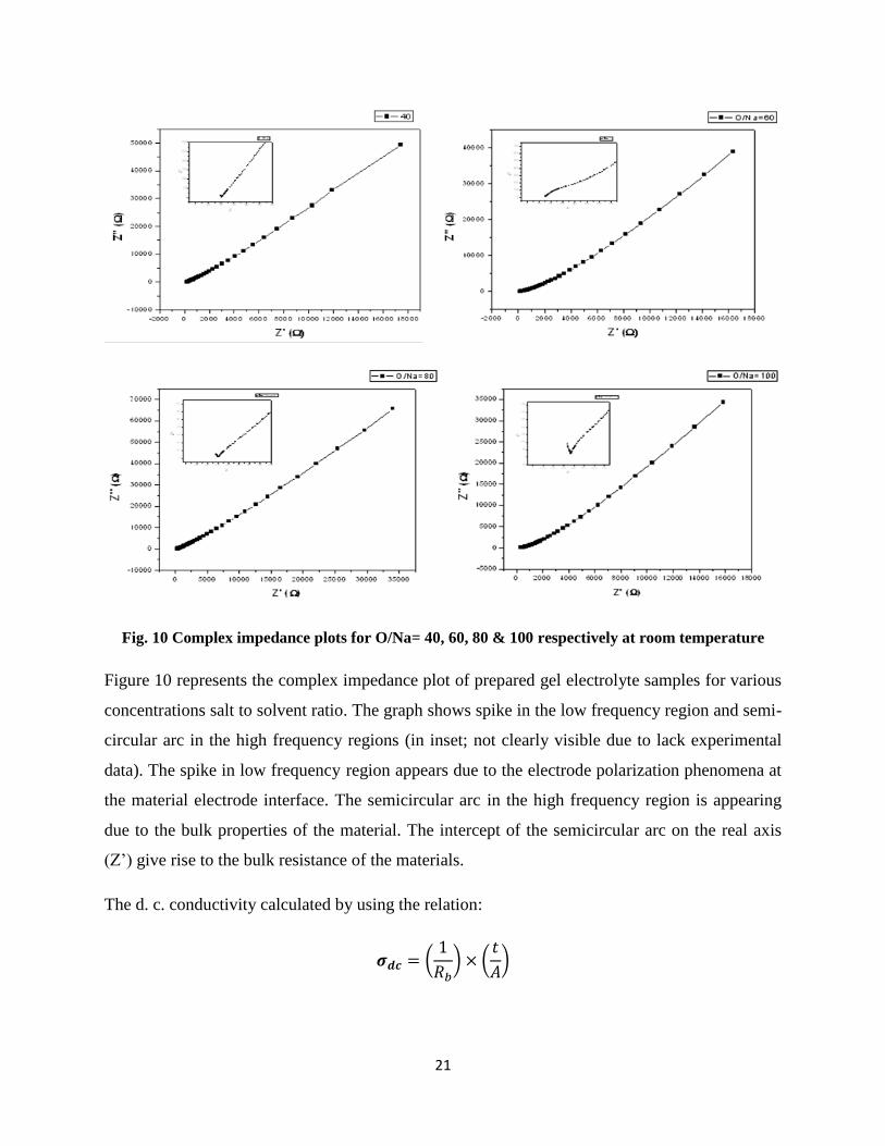
Fig. 8 vs Frequency plots for O/Na= 20, 40, 60, 80 & 100
10-1
100
101
102
103
104
105
106
101
102
103
104
105
106
107
r
Frequency(Hz)
O/Na=60
O/Na=80
O/Na=100
O/Na=20
O/Na=40

20
Figure 8. shows the variation of relative permittivity ( ) with frequency for different O/Na ratio.
From the graph we can observe that has higher values at lower frequency which decreases
sharply with increase in frequency. Decrease in dielectric constant with increase in frequency is
due to the dipolar relaxation. The low frequency region where there is sharp decrease in
dielectric constant is observed may be due to electrode polarization phenomena.
Fig. 9 tan δ vs Frequency plots for O/Na= 40, 60, 80 & 100
Fig.9 shows the variation of tangent loss with frequency for different compositions of the prepared
polymer gel electrolyte samples. The peak position is different for different compositions. The
appearance of peaks suggests the presence of relaxing dipoles in the samples.
0.1 1 10 100 1000 10000 100000 1000000
0
5
10
15
20
25
30
35
40
tan
Frequency(Hz)
O/Na=40
O/Na=60
O/Na=80
O/Na=100
21
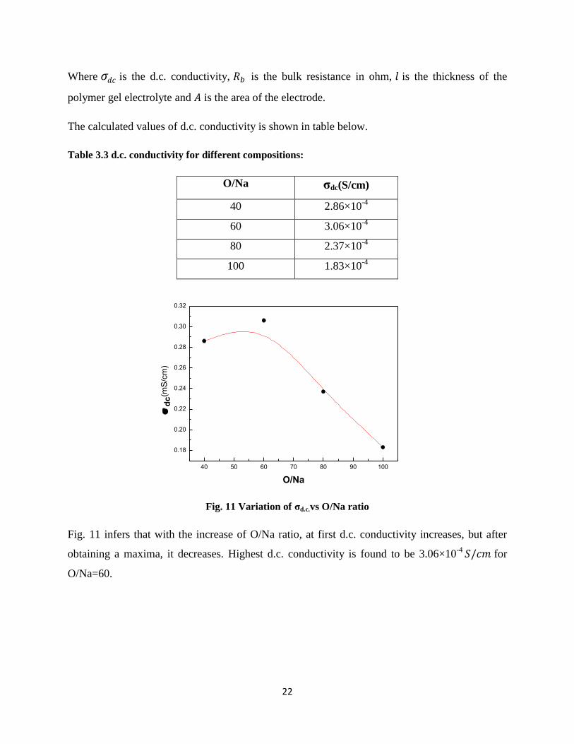
Fig. 10 Complex impedance plots for O/Na= 40, 60, 80 & 100 respectively at room temperature
Figure 10 represents the complex impedance plot of prepared gel electrolyte samples for various
concentrations salt to solvent ratio. The graph shows spike in the low frequency region and semi-
circular arc in the high frequency regions (in inset; not clearly visible due to lack experimental
data). The spike in low frequency region appears due to the electrode polarization phenomena at
the material electrode interface. The semicircular arc in the high frequency region is appearing
due to the bulk properties of the material. The intercept of the semicircular arc on the real axis
(Z’) give rise to the bulk resistance of the materials.
The d. c. conductivity calculated by using the relation:
(
) (
)
22
Where is the d.c. conductivity, is the bulk resistance in ohm, is the thickness of the
polymer gel electrolyte and is the area of the electrode.
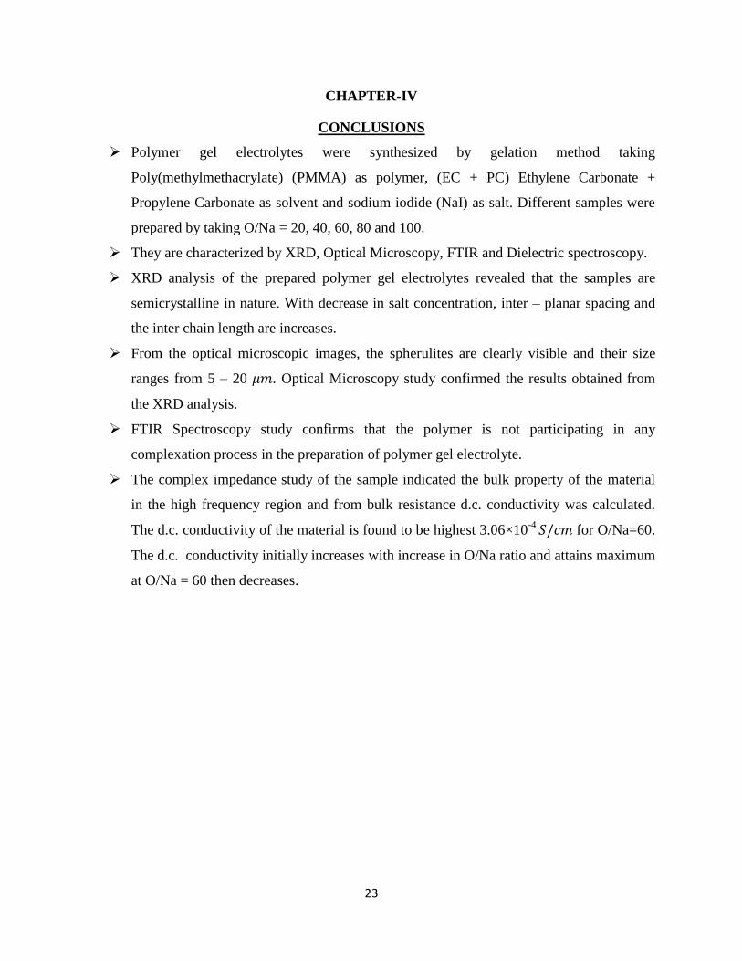
The calculated values of d.c. conductivity is shown in table below.
Table 3.3 d.c. conductivity for different compositions:
O/Na σdc(S/cm)
40 2.86×10⁻⁴
60 3.06×10⁻⁴
80 2.37×10⁻⁴
100 1.83×10⁻⁴
Fig. 11 Variation of σd.c.vs O/Na ratio
Fig. 11 infers that with the increase of O/Na ratio, at first d.c. conductivity increases, but after
obtaining a maxima, it decreases. Highest d.c. conductivity is found to be 3.06×10⁻⁴ for
O/Na=60.
40 50 60 70 80 90 100
0.18
0.20
0.22
0.24
0.26
0.28
0.30
0.32
d
c(m
S/c
m)
O/Na
23
CHAPTER-IV
CONCLUSIONS
Polymer gel electrolytes were synthesized by gelation method taking
Poly(methylmethacrylate) (PMMA) as polymer, (EC + PC) Ethylene Carbonate +
Propylene Carbonate as solvent and sodium iodide (NaI) as salt. Different samples were
prepared by taking O/Na = 20, 40, 60, 80 and 100.
They are characterized by XRD, Optical Microscopy, FTIR and Dielectric spectroscopy.
XRD analysis of the prepared polymer gel electrolytes revealed that the samples are
semicrystalline in nature. With decrease in salt concentration, inter – planar spacing and
the inter chain length are increases.
From the optical microscopic images, the spherulites are clearly visible and their size
ranges from 5 – 20 𝜇 . Optical Microscopy study confirmed the results obtained from
the XRD analysis.
FTIR Spectroscopy study confirms that the polymer is not participating in any
complexation process in the preparation of polymer gel electrolyte.
The complex impedance study of the sample indicated the bulk property of the material
in the high frequency region and from bulk resistance d.c. conductivity was calculated.
The d.c. conductivity of the material is found to be highest 3.06×10⁻⁴ for O/Na=60.
The d.c. conductivity initially increases with increase in O/Na ratio and attains maximum
at O/Na = 60 then decreases.

24
REFERENCES:
1. Wikipedia Electrolyte
2. E. A. Secco, “Solid State Ionics-Materials and Applications”, edited by B. V. R.
Chowdari, S. Chandra, S. Singh and P.C. Srivastava (World Scientific, Singapore, 1992)
3. B. Scrosati, C.A. Vincent, MRS Bull. 25-28, (2000)
4. S.Chandra, “Superionic Solids- Principle and Applications”, (North Holland, Amsterdam,
1981)
5. G. C. Farrington, “Solid State Batteries”, edited by C. A.C. Sequeira and A. Hooper
(Martinus Nijhoff, Dordrecht, 1985)
6. S.S. Sekhon, Phys. News, Bull. Indian Phys. Assoc. 26(1995) 80.
7. F.M. Gray, Polymer Electrolytes, (Royal Science of Chemistry, 1999)
8. Li Libo, Wang Jiajia, Yang Peixia, Guo Shaowen, Wang Heng, Yang Xiuchun, Ma
Xuwei, Yang Shuo, Wu Baohua, Electrochimica Acta, (2010)
9. S. Chandra and A. Chandra, Proc. Natl. Acad. Sci., India 64 (1994) 141.
10. Samuel Glasstone, “An introduction to Electrochemistry”, (Litton educational publisher,
1974)
11. D. Brinkmann, “Recent Advances in Fast Ion Conducting Materials and Devices”, edited
by B. V. R. Chowdari, Q. Liu and L. Chen (World Scientific, Singapore, 1990)
12. W. Wieczorek, K Such, J Przyluski and Z Florianczyk, 1991 Synth. Met. 45 373.
13. JJ Song, YY Wang, CC Wan, Review of gel-type polymer electrolytes for lithium ion
batteries. J Power Sources 1999; 77:183
14. J E Weston and B C H Steele, Solid State Ion. 7, 75, (1982)
15. J. R. Mac Cullum, C.A. Vincent (ed) 1987-1989 Polymer Electrolyte Reviews vol I, II
(London: Elsevier Applied Sciences).
16. M. Deepa, N. Sharma, S.A. Agnihotry, S. Singh, T. Lal, R. Chandra Solid State Ionics
152– 153, 253– 258, (2002)
17. Z. Osman, M.I. MohdGhazali, L. Othman, K.B. Md Isa, Electrochimica Acta, 2, 1-4,
(2012)
18. Hee-Tak Kim, Kyoung-Bae Kim, Sun-Wook Kim, Jung-Ki Park Electrochimica Acta,
45, 4001–4007, (2000)

25
19. X.Helan Flora, M.Ulaganathan, S.Rajendran Int. J. Electrochem. Sci.,7, 7451 – 7462
(2012)
20. A.Manuel Stephan Electrochimica Acta., 42, 21-42, (2006)
21. Jiri Vondrak, Marie Sedlarkova, Jana Velicka, BretislavKlapste, Vtezslav Novak , Jakub
Reiter, Electrochimica Acta, 46, 2047–2048, (2001)
22. Y.H. Liao, D.Y. Zhou, M.M. Rao, W.S. Li, Z.P. Cai, Y. Liang, C.L. Tan, Journal of
Power Sources,189,139–144, (2001)
23. Hong-Ryun Jung, Wan-Jin Lee, Electrochimica Acta, 58, 674-680 (2001)
24. S.N. Asmara, M.Z. Kufian, S.R. Majid, A.K. Arof, Electrochimica Acta,57, 91-97,
(2011)
25. Hee-Jin Rhoo, Hee-Tak Kim, Jung-Ki Park and Taek-Sung Hwangb, Electrochimica
Acta, 42, 1571-1579 (1997)
26. D.Saikia, A.Kumar , Europian Polymer Journal,41, 563-568 (2005)
27. S. Rajendran, T. Uma, Materials Letters,45, 191–196 (2000)
28. Xinping Hou, Kok Siong Siow, Polymer,41, 8689–8696 (2000)
29. A.M. Voice, J.P. Southhall, V.Rogers, K.H. Mathews, G.R. Davies, J.E. Mclntyre & I.M.
Ward, Polymer, 35, 16 (1994)
30. D.O. Hummel, “Infrared spectra of polymers in the medium and long wavelength
regions” (New York: John Wiley & Sons; 1966)
31. P.G. Bruce and C. A. Vincent, Journal of chemical society Faraday Trans. 89 (1993)
3187
32. W.K. Lee, W.J. Cho, C.S. Ha, A. Takahara, T. Kajiyama, Polymer 1996;36:1229
33. W. Wieczorek, R.J. Stevens, Phys. Chem. B 1997;101:1529
34. R.M. Silverstein, F.X. Webster, “Spectroscopic identification of organic compounds”
(6th ed. New York: John Wiley and Sons; 1997)
35. B.S. Furniss, A.J. Hannaford, PWG Smith, AR Tatchell, “Vogel’s text book of practical
organic chemistry” (5th
ed. London: Addison Wesley Longman; 1989)