Synthesis and Characterization of Carbon Fibers …...The carbon fiber of various concentrations...
14
PEER-REVIEWED ARTICLE bioresources.com Khan et al. (2013). “Carbon fibers and wood composite,” BioResources 8(3), 4171-4184. 4171 Synthesis and Characterization of Carbon Fibers and their Application in Wood Composites Tanveer Ahmed Khan, a Arun Gupta, a, * Saidatul Shima Jamari, a Rajan Jose, b Mohammed Nasir, a and Anuj Kumar a Carbon fibers were synthesized using a low-cost, economical method. Fresh rubber wood fibers (Hevea brasiliensis) were burned using a furnace in an inert condition at 350 to 450 o C for 2-4 hours, and after that the fibers were ground at 18000 rpm for 20 to 40 seconds. The effect of carbon fibers as a reinforcement agent on mechanical, physical, and morphological properties was investigated. In the composite preparation, carbon fiber dosages (0, 0.1, 0.25, and 0.5 wt.%) were used as variable factors, along with a urea formaldehyde content of 10%. The morphology of the specimens was characterized using X-ray diffraction (XRD), Thermogravimetric analysis (TGA), and Field Emission Scanning Electron Microscopy (FESEM). The mechanical tests indicated that when carbon fibers were added, the modulus of rupture (MOR) and internal bonding strength (IB) improved significantly. From the TGA graph it was observed that the thermal stability of the composites based on carbon fiber was higher than composites without it. The thermocouple readings showed that at a higher loading of carbon, the core temperature of the board increased faster than for the control board. Keywords: Urea-formaldehyde; MDF; Wood composite; Carbon fiber Contact information: a: Faculty of Chemical and Natural Resource Engineering, University Malaysia Pahang; b: Faculty of Industrial Science and Technology, University Malaysia Pahang, 26300, Kuantan, Pahang, Malaysia; *E-mail: [email protected] INTRODUCTION Medium-density fiber board (MDF) is an engineered wood product composed of fine ligno-cellulosic fibers combined with a synthetic resin and subjected to heat and pressure to form panels (Irle and Barbu 2010). It is made up of wood fibers and can be used as a building material similar in application to plywood. It is stronger and much denser than normal particleboard. The low thermal conductivity of wood fiber limits the production rates in existing production lines. The carbon fibers can be used as a filler to improve the thermal and mechanical properties of wood composite. Carbon fibers are widely employed in various fields because of their unique properties including adsorptive capacity, chemical stability, thermal conductivity, and electrical conductivity (Youssef et al. 2008; Yun et al. 2008; Kim et al. 2008; Roh et al. 2008). Principles of composites demonstrate that for a given reinforcement and matrix, the properties of resultant composites are mainly dependent on interfacial adhesion, because a good interfacial adhesion guarantees effective transition of stress, and thus the reinforcement and matrix can take full action. However, a large number of studies have shown that the surfaces of carbon fibers exhibit inertness, and the interfacial adhesion
Transcript of Synthesis and Characterization of Carbon Fibers …...The carbon fiber of various concentrations...

PEER-REVIEWED ARTICLE bioresources.com
Khan et al. (2013). “Carbon fibers and wood composite,” BioResources 8(3), 4171-4184. 4171
Synthesis and Characterization of Carbon Fibers and their Application in Wood Composites Tanveer Ahmed Khan,
a Arun Gupta,
a,* Saidatul Shima Jamari,
a Rajan Jose,
b
Mohammed Nasir,a and Anuj Kumar
a
Carbon fibers were synthesized using a low-cost, economical method. Fresh rubber wood fibers (Hevea brasiliensis) were burned using a
furnace in an inert condition at 350 to 450 oC for 2-4 hours, and after that
the fibers were ground at 18000 rpm for 20 to 40 seconds. The effect of carbon fibers as a reinforcement agent on mechanical, physical, and morphological properties was investigated. In the composite preparation, carbon fiber dosages (0, 0.1, 0.25, and 0.5 wt.%) were used as variable factors, along with a urea formaldehyde content of 10%. The morphology of the specimens was characterized using X-ray diffraction (XRD), Thermogravimetric analysis (TGA), and Field Emission Scanning Electron Microscopy (FESEM). The mechanical tests indicated that when carbon fibers were added, the modulus of rupture (MOR) and internal bonding strength (IB) improved significantly. From the TGA graph it was observed that the thermal stability of the composites based on carbon fiber was higher than composites without it. The thermocouple readings showed that at a higher loading of carbon, the core temperature of the board increased faster than for the control board.
Keywords: Urea-formaldehyde; MDF; Wood composite; Carbon fiber
Contact information: a: Faculty of Chemical and Natural Resource Engineering, University Malaysia
Pahang; b: Faculty of Industrial Science and Technology, University Malaysia Pahang, 26300, Kuantan,
Pahang, Malaysia; *E-mail: [email protected]
INTRODUCTION
Medium-density fiber board (MDF) is an engineered wood product composed of
fine ligno-cellulosic fibers combined with a synthetic resin and subjected to heat and
pressure to form panels (Irle and Barbu 2010). It is made up of wood fibers and can be
used as a building material similar in application to plywood. It is stronger and much
denser than normal particleboard.
The low thermal conductivity of wood fiber limits the production rates in existing
production lines. The carbon fibers can be used as a filler to improve the thermal and
mechanical properties of wood composite. Carbon fibers are widely employed in various
fields because of their unique properties including adsorptive capacity, chemical stability,
thermal conductivity, and electrical conductivity (Youssef et al. 2008; Yun et al. 2008;
Kim et al. 2008; Roh et al. 2008).
Principles of composites demonstrate that for a given reinforcement and matrix,
the properties of resultant composites are mainly dependent on interfacial adhesion,
because a good interfacial adhesion guarantees effective transition of stress, and thus the
reinforcement and matrix can take full action. However, a large number of studies have
shown that the surfaces of carbon fibers exhibit inertness, and the interfacial adhesion

PEER-REVIEWED ARTICLE bioresources.com
Khan et al. (2013). “Carbon fibers and wood composite,” BioResources 8(3), 4171-4184. 4172
between carbon fibers and organic resin matrix is generally very weak (Meng et al. 2009;
Xu et al. 2007; Lu et al. 2007). Hence, how to improve the interfacial adhesion between
carbon fibers and resin matrix has been one of the most important topics of developing
advanced composites.
Many theories or models have been proposed to explain or forecast the effect of
surface modification of carbon fibers on the interfacial adhesion of resultant composites.
To date, it is generally believed by many researchers that the chemical interaction
between carbon fibers and polymeric matrix is necessary to improve the interfacial
adhesion; however, some scholars have recently stated that good interfacial adhesion
between carbon fibers and matrix can be also obtained by the formation of physical
interaction. For example, Lu et al. (2007) employed air plasma to modify carbon fibers,
and they concluded that mechanical interaction has a dominant effect on the interfacial
adhesion of composites. The application of nano-based materials opens new aspects in
the field of wood science, such as their use in solid wood, wood-based panels, etc. (Cai et
al. 2007a, 2007b, 2008, and 2010). Mixing of carbon fibers has improved the thermal and
mechanical properties of the wood composite boards.
This work was aimed at analyzing the influence of using carbon fibers as a
reinforcing agent on the physico-mechanical properties of wood composites. Experiments
were conducted to estimate the curing time at different weight concentrations of carbon
fibers when mixed with resin and wood fibers. In the present work, the surface
morphology and carbon fibers distribution in the composites have also been studied. The
novelty of this work is the use of carbon fibers in wood composite for the first time.
MATERIALS AND METHODS
Materials Wood Fibers
The lignocellulosic material used for this study was fresh rubber wood (Hevea
brasiliensis) fibers obtained from Robin Resources Pvt. Ltd.
Urea formaldehyde
Urea-formaldehyde (UF) liquid resin used for this study was obtained from Dynea
Malaysia Sdn. Bhd. The viscosity of the UF resin at 300 oC was 178 centipoises, pH 8.79,
density 1.286 kg/m3, and the gel time at 100
oC was 36 s.
Methods Preparation of carbon fibers
The fresh rubber wood fibers (Hevea brasiliensis) were burned using a furnace in
an inert condition at 350 to 450 oC for 2 to 4 h. After that the fibers were ground with a
Retsch Chemical Grinder ZM 200 at 18000 rpm for 20 to 40 seconds. The purity of the
carbon fibers was found to be 74.09% using an elemental analysis system (CHNS
analyzer).
Mixing of carbon fiber with UF resin
A bench-top overhead mixer IKA®-WERKE, model RW 20 DZM, with a speed
range of 72 to 2000 rpm was used for pre-mixing carbon fiber with the UF resin at 1800

PEER-REVIEWED ARTICLE bioresources.com
Khan et al. (2013). “Carbon fibers and wood composite,” BioResources 8(3), 4171-4184. 4173
rpm for 30 min. The weight fraction of carbon fiber and UF resin were based on the
weight fraction of the oven dry wood fibers. After mixing the carbon fibers and UF resin
in a bench-top mixer, the resin mixture samples were subjected to ultrasonic treatment
with NANO-LAB Ultrasonic probe dispersion QS1 system for 1 h for uniform mixing of
nanoparticles in UF resin. This procedure was used to prepare three samples with carbon
fiber concentrations of 0.1%, 0.25%, and 0.5% by weight in the UF resin.
Preparation of MDF panels
The standard laboratory method was followed to manufacture 300 mm x 300 mm
x 15 mm MDF boards of 800 kg/m3. Rubber wood fiber in an amount of 750 g at 12%
moisture content was used to prepare MDF. A rotary drum blender was used to blend the
wood fibers, carbon fibers, and UF resin uniformly. The drum consists of steel dowels
arranged in a zigzag pattern, which were intended to facilitate tumbling and mixing with
a rotational speed of 18 rpm. The carbon fiber of various concentrations (0%, 0.1%,
0.25%, and 0.5%) mixed into 10% resin (all percentages are calculated from weight of
wood fiber) was sprayed with a spray gun on the wood fibers. A puff mat of 300 x
300 mm was prepared from the resin added wood fiber, which was then pre-pressed at
1.5 MPa pressure. Finally, the pre-pressed panel was hot-pressed at 180 oC for 450 s with
a target thickness of 15 mm; Fig. 1 shows the images of MDF samples. Except for the
carbon fiber concentration, all the experimental parameters such as fiber moisture, resin
loading, pressing time, and platen temperature were maintained the same in all
experiments.
Fig. 1. Images of MDF samples (a) the 300mm x 300mm x 15mm MDF board, (b) for internal bonding, (c) for modulus of rupture
The MDF board was fabricated into two different sets as presented in Fig. 2. The
first set of boards were used to find the temperature profile inside the core of mat during
hot pressing and second set of boards were used to find the physical and mechanical
properties. For the core temperature analysis, three replicates of each treatment, i.e. a
PEER-REVIEWED ARTICLE bioresources.com
Khan et al. (2013). “Carbon fibers and wood composite,” BioResources 8(3), 4171-4184. 4174
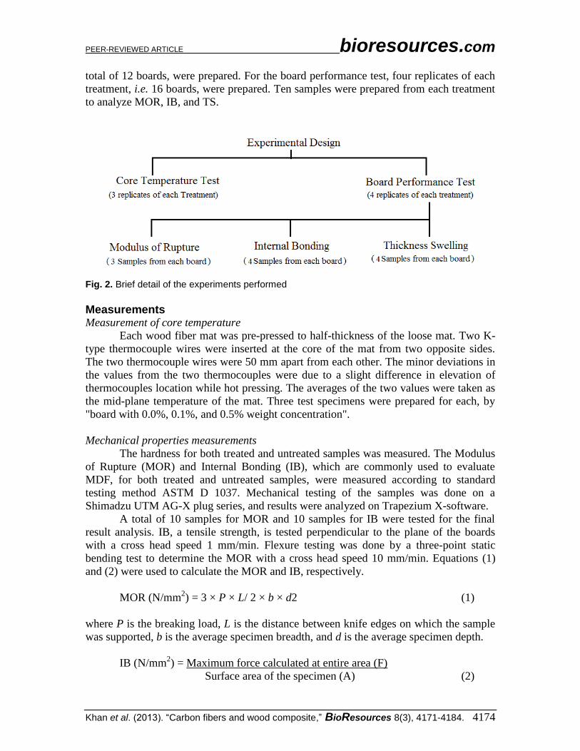
total of 12 boards, were prepared. For the board performance test, four replicates of each
treatment, i.e. 16 boards, were prepared. Ten samples were prepared from each treatment
to analyze MOR, IB, and TS.
Fig. 2. Brief detail of the experiments performed
Measurements Measurement of core temperature
Each wood fiber mat was pre-pressed to half-thickness of the loose mat. Two K-
type thermocouple wires were inserted at the core of the mat from two opposite sides.
The two thermocouple wires were 50 mm apart from each other. The minor deviations in
the values from the two thermocouples were due to a slight difference in elevation of
thermocouples location while hot pressing. The averages of the two values were taken as
the mid-plane temperature of the mat. Three test specimens were prepared for each, by
"board with 0.0%, 0.1%, and 0.5% weight concentration".
Mechanical properties measurements
The hardness for both treated and untreated samples was measured. The Modulus
of Rupture (MOR) and Internal Bonding (IB), which are commonly used to evaluate
MDF, for both treated and untreated samples, were measured according to standard
testing method ASTM D 1037. Mechanical testing of the samples was done on a
Shimadzu UTM AG-X plug series, and results were analyzed on Trapezium X-software.
A total of 10 samples for MOR and 10 samples for IB were tested for the final
result analysis. IB, a tensile strength, is tested perpendicular to the plane of the boards
with a cross head speed 1 mm/min. Flexure testing was done by a three-point static
bending test to determine the MOR with a cross head speed 10 mm/min. Equations (1)
and (2) were used to calculate the MOR and IB, respectively.
MOR (N/mm2) = 3 × P × L/ 2 × b × d2 (1)
where P is the breaking load, L is the distance between knife edges on which the sample
was supported, b is the average specimen breadth, and d is the average specimen depth.
IB (N/mm2) = Maximum force calculated at entire area (F)
Surface area of the specimen (A) (2)
PEER-REVIEWED ARTICLE bioresources.com
Khan et al. (2013). “Carbon fibers and wood composite,” BioResources 8(3), 4171-4184. 4175
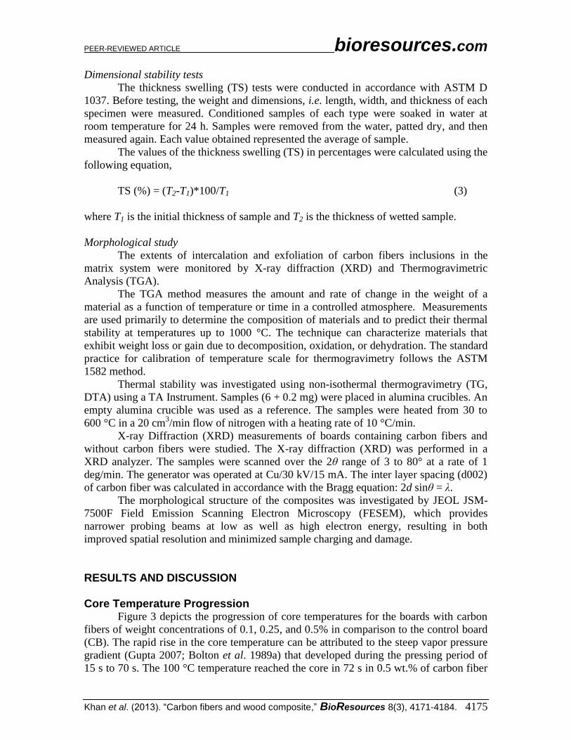
Dimensional stability tests
The thickness swelling (TS) tests were conducted in accordance with ASTM D
1037. Before testing, the weight and dimensions, i.e. length, width, and thickness of each
specimen were measured. Conditioned samples of each type were soaked in water at
room temperature for 24 h. Samples were removed from the water, patted dry, and then
measured again. Each value obtained represented the average of sample.
The values of the thickness swelling (TS) in percentages were calculated using the
following equation,
TS (%) = (T2-T1)*100/T1 (3)
where T1 is the initial thickness of sample and T2 is the thickness of wetted sample.
Morphological study
The extents of intercalation and exfoliation of carbon fibers inclusions in the
matrix system were monitored by X-ray diffraction (XRD) and Thermogravimetric
Analysis (TGA).
The TGA method measures the amount and rate of change in the weight of a
material as a function of temperature or time in a controlled atmosphere. Measurements
are used primarily to determine the composition of materials and to predict their thermal
stability at temperatures up to 1000 °C. The technique can characterize materials that
exhibit weight loss or gain due to decomposition, oxidation, or dehydration. The standard
practice for calibration of temperature scale for thermogravimetry follows the ASTM
1582 method.
Thermal stability was investigated using non-isothermal thermogravimetry (TG,
DTA) using a TA Instrument. Samples (6 + 0.2 mg) were placed in alumina crucibles. An
empty alumina crucible was used as a reference. The samples were heated from 30 to
600 °C in a 20 cm3/min flow of nitrogen with a heating rate of 10 °C/min.
X-ray Diffraction (XRD) measurements of boards containing carbon fibers and
without carbon fibers were studied. The X-ray diffraction (XRD) was performed in a
XRD analyzer. The samples were scanned over the 2θ range of 3 to 80° at a rate of 1
deg/min. The generator was operated at Cu/30 kV/15 mA. The inter layer spacing (d002)
of carbon fiber was calculated in accordance with the Bragg equation: 2d sinθ = λ.
The morphological structure of the composites was investigated by JEOL JSM-
7500F Field Emission Scanning Electron Microscopy (FESEM), which provides
narrower probing beams at low as well as high electron energy, resulting in both
improved spatial resolution and minimized sample charging and damage.
RESULTS AND DISCUSSION Core Temperature Progression
Figure 3 depicts the progression of core temperatures for the boards with carbon
fibers of weight concentrations of 0.1, 0.25, and 0.5% in comparison to the control board
(CB). The rapid rise in the core temperature can be attributed to the steep vapor pressure
gradient (Gupta 2007; Bolton et al. 1989a) that developed during the pressing period of
15 s to 70 s. The 100 °C temperature reached the core in 72 s in 0.5 wt.% of carbon fiber

PEER-REVIEWED ARTICLE bioresources.com
Khan et al. (2013). “Carbon fibers and wood composite,” BioResources 8(3), 4171-4184. 4176
compared to the control where the temperature reached the core in 84 s, indicating that
conductivity can be increased by using carbon fibers. In pressing time phase from 112 s
to 172 s, a constant temperature in the central plane was observed; this could be ascribed
to phase change occurring in the board. The vapor formed was observed to exit from the
edges of the board due to higher vapour pressure formed at the core. From the time
period of 172 s, a gradual rise in the central plane was observed, which is mainly due to
heat conduction in the board. It could be observed that the conductivity of boards
prepared with carbon fibers was increased.
Fig. 3. Core temperature profile of mat during hot-pressing of MDF panels with different weight fraction % of carbon fibers
Enhanced Properties of the MDF Internal Bonding (IB)
Figure 4 depicts the average internal bonding strength of composites made with
various weight percentages of carbon fibers and 10% urea formaldehyde loadings. The
bonding strength results show that the composites containing 0.1 wt% of carbon
exhibited more internal bonding strength compared to samples without it. This could be
possibly due to better adhesion between matrix (carbon fibers and urea formaldehyde)
and wood fibers, which cause tension concentration in medium density fiberboards. It is
seen from Fig. 4 that unlike 0.1 wt% of carbon fibers, internal bonding strength decreased
with addition of carbon fibers, as can be seen in 0.25 wt% and 0.5 wt% of carbon fibers.
Reduction of bonding strength with increasing carbon fibers can be related to the increase
of the probability for agglomeration that creates regions of stress concentrations that
require less energy to elongate the crack propagation (Eitan et al. 2003). This is
consistent with the results reported by most authors studying the subject (Ashori et al.
2012; Tavasoli Farsheh et al. 2011; Ziaei Tabari et al. 2011). In general, the results for
internal bonding strength test showed that medium density fiberboards, which contain 0.1
wt%, had the highest bonding strength value.

PEER-REVIEWED ARTICLE bioresources.com
Khan et al. (2013). “Carbon fibers and wood composite,” BioResources 8(3), 4171-4184. 4177
Fig. 4. Internal bonding results of MDF based on different ratios of carbon fibers and control board (without carbon fiber)
Modulus of Rupture (MOR)
The average values of MOR properties that were calculated and compared with
the control specimen are shown in Fig. 5.
Fig. 5. Comparison of modulus of rupture (MOR) between control MDFs and MDF with different carbon fiber loading

PEER-REVIEWED ARTICLE bioresources.com
Khan et al. (2013). “Carbon fibers and wood composite,” BioResources 8(3), 4171-4184. 4178
There was no significant difference in MOR values. The MOR results showed
that the MDF panels containing 0.1% carbon fiber exhibited higher MOR values as
compared to MDF without carbon fiber (control board). This may be due to the improved
adhesion between components in the MDF. The MOR of MDF at higher carbon fiber
loading did not increase; this may be due to carbon fiber agglomerates. Tavasoli Farsheh
et al. (2011) reported that modulus of composites at higher CNT loading may fail to
increase because of CNT agglomerates. The MOR of MDF panels was increased when
using 0.1 and 0.25 wt% carbon, and it was decreased when using 0.5 wt% of carbon
fiber. There was improvement of MOR with the addition of 0.25 wt% of carbon fiber,
and the maximum increase of MOR was observed in MDF panels with 0.1 wt% of carbon
fibers, i.e. 44.7.
Thickness Swelling Test
Figure 6 shows the percentage of the water uptake for the composites after 24 h of
immersion in water. It can be seen that thickness swelling was not improved by adding
different percentages of carbon fibers as compared to panels without the addition of
carbon fibers.
Thickness swelling can be reduced significantly with the addition of carbon
fibers, but for this case, the TS was not improved. This may be due to the agglomeration
of carbon fibers, which vary depending upon the carbon fibers and UF.
Fig. 6. Thickness swelling results of MDF based on different ratios of carbon fiber and control board (without carbon fiber)
Morphological Characteristics Thermogravimetry (TGA)
TGA results of MDF based on different ratios of carbon fibers and control board
(without carbon fiber) are shown in Fig. 7. The thermal stability of samples was

PEER-REVIEWED ARTICLE bioresources.com
Khan et al. (2013). “Carbon fibers and wood composite,” BioResources 8(3), 4171-4184. 4179
determined by using thermogravimetric analysis (TGA). In this test, the thermal stability
was studied in terms of the weight loss as a function of temperature in a nitrogen
atmosphere.
Fig. 7. TGA results of MDF based on different ratios of carbon fibers and control board (without carbon fiber)
The char yields at different temperatures are summarized in Table 1. It can be
seen from the TGA curves that MDF based on different ratios of carbon fibers and
control board exhibited two distinct stages of decomposition. The first stage of
decomposition may be related to the vaporization of moisture in the composites. The
second stage of decomposition may be related to degradation of fibers, urea
formaldehyde, and its additives. It can also be seen that the major degradation for all
samples occurred in the temperature range of 250 to 350 °C.
Table 1. Thermal Properties of MDF Containing Carbon Fibers and MDF without Carbon Fibers Samples Char yield at different temperature (%) Tmax
(°C) 100 °C 200 °C 300 °C 400 °C 500 °C 600 °C
Control Board
95.31 93.9 59.76 30.45 17.41 8.629 253.16
CF 0.1% 93.34 92.04 58.98 29.08 20.34 14.91 257.53
CF 0.25% 97.87 96.5 62.93 27.35 23.74 22.15 265.68
CF 0.5% 94.18 93 60.6 26.64 23 21.55 266.66

PEER-REVIEWED ARTICLE bioresources.com
Khan et al. (2013). “Carbon fibers and wood composite,” BioResources 8(3), 4171-4184. 4180
From the amounts of residue at low temperatures from 50 to 240 °C, it can be
seen that the presence of carbon fibers slightly increased the rate of sample degradation
compared to that without carbon fibers. But, the maximum decomposition temperature
(Tmax) of the composites slightly changed after the addition of carbon fibers. The
maximum decomposition temperature of MDF without using carbon fiber and with using
carbon fibers with 0 wt%, 0.1 wt%, 0.25 wt%, and 0.5 wt% carbon fibers were 253.16,
257.53, 265.68, and 266.66 °C, respectively. However, at higher temperatures, MDF with
carbon fibers performed better in thermal stability than without carbon fibers with a
higher char residue of 22.15 wt% at 600 °C. It was reported in previous studies that the
addition of nano-clay platelets would efficiently raise the char residue of polymers at
high temperatures (Hwang et al. 2010; Madaleno et al. 2010; Chatterjee and Islam 2008;
Ismail et al. 2008).
There was little difference between the curves of composites based on carbon
fiber with 0.1, 0.25, and 0.5 wt% carbon fiber; such an effect can be attributed to the
good dispersion in the polymer matrix. From Fig. 7 it is obvious that the thermal stability
of the composites, based on carbon fiber, was higher than composites based on only UF,
and it was improved by the addition of carbon fiber. By increasing the carbon fiber
percentage, the thermal stability was enhanced.
XRD Analysis XRD was applied to investigate the crystal structure of as-grown samples. Figure
8 shows the X-ray diffraction patterns of the (a) MDF containing only UF (control
board), (b) MDF containing UF with 0.1 wt% of carbon fiber, (c) MDF containing UF
with 0.25 wt% of carbon fiber, and (d) MDF containing UF with 0.50 wt% of carbon
fiber. The diffraction pattern of the control board shows a high narrow diffraction peak at
2θ = 23.09°, corresponding to the C (002) reflection of a turbostratic carbon structure of
MDF.
Fig. 8. XRD pattern of MDF containing different ratios of carbon fibers

PEER-REVIEWED ARTICLE bioresources.com
Khan et al. (2013). “Carbon fibers and wood composite,” BioResources 8(3), 4171-4184. 4181
After the growth of carbon fibers on the MDF, C(002) reflection become stronger,
demonstrating that the structure order degree of the as-grown micro–nano carbon fiber in
MDF increased significantly compared to the control board (MDF without carbon fibers).
The average d-spacing (d0 0 2) values were calculated based on the Bragg equation (nλ =
2d sin θ), determining the interlayer distance of composite matrix. The broad asymmetric
peak values for MDF without carbon fiber, MDF with 0.1 wt% carbon fiber, MDF with
0.25 wt% carbon fiber, and MDF with 0.5 wt% carbon fiber were located at 2θ = 23.09,
23.04, 22.80, and 22.70. Structural parameters for the materials investigated are given in
Table 3. These show that they all contain disordered graphite microcrystallites, with
inter-crystallite and intra-crystallite voids forming the pores. In fact, sharp narrow
diffraction peaks show crystalline structures, while the broad peak corresponds to an
amorphous structure. XRD pattern of MDF containing different ratios of carbon fibers
indicate that changes in the network structure occurred in the amorphous region of the UF
resin. In other words, the amorphous region was the important point of entry for moisture
reaching the central layer of the compact solid carbon fiber composites. Table 2. Peak List
2-theta (deg) d (ang.) Phase name
23.09(11) 3.849(18) Control Board
34.46(18) 2.600(13) Control Board
23.04(12) 3.86(2) 0.1 % CF
15.6(3) 5.68(11) 0.25 % CF
22.80(4) 3.897(6) 0.25 % CF
29.0(9) 3.07(9) 0.25 % CF
15.48(8) 5.72(3) 0.50 % CF
22.70(3) 3.913(5) 0.50 % CF
34.7(6) 2.58(4) 0.50 % CF
Field Emission Scanning Electron Microscopy (FESEM) Analysis FESEM is an effective media for the morphological investigations of composites.
Figure 9(a) corresponds to MDF without carbon fibers and with carbon fiber, which
shows some evidence that fiber has been pulled out from the matrix. Therefore when
stress is applied, it causes the fibers to leave the matrix easily and makes gaping holes.
Besides this, there were some cavities in the surface that could absorb water and/or
reduce mechanical properties. This indicates that the level of interfacial bonding between
the fibers and UF in the composites without filler was weak. Figure 9(b) illustrates
composite with 0.1 wt% carbon fiber; it was observed that there was no separation of the
fibers from the matrix. Very good interaction between the components can be inferred
from the image, where white arrows represent the presence of carbon fibers in
composites. The strong adhesion that was observed at the interface has already been
discussed in terms of the mechanical properties of the composites and is related to the
coupling agent, which encapsulated the fibers in the matrix and facilitated strong
bonding. The significant decrease in water absorption and thickness swelling of the
treatment including 0.25 wt% carbon fiber and 0.5 wt% carbon fiber is further supported
by Fig. 9(c) and 9(d), which show that when composite micro voids and the lumens of
fibers were filled with carbon fibers, there was a smooth and uniform matrix without any
holes and that penetration of water into the deeper holes and cavities of the composite
was prevented.

PEER-REVIEWED ARTICLE bioresources.com
Khan et al. (2013). “Carbon fibers and wood composite,” BioResources 8(3), 4171-4184. 4182
(a) (b)
(c) (d)
Fig. 9. FESEM micrographs at 8 kX magnification of (a) the surface of samples without carbon fiber, (b) with 0.1 wt% carbon fiber, (c) with 0.25 wt% carbon fiber, and (d) with 0.5 wt% carbon fiber
CONCLUSION
This study investigated the effect of carbon fibers as well as urea formaldehyde
on the physical and mechanical properties of MDF boards. The mechanical properties of
the MDF board were improved due to the stronger interfacial bonding between the fiber
and the matrix polymer. Addition of carbon fibers improved the Internal Bonding (IB).
The IB was increased by 0.5126 to 0.7227 (0.1 wt% carbon fiber). Among the various
formulations, composites containing 0.1 wt% of carbon fibers gave the maximum
improvement in both mechanical and physical properties. There was improvement in core
temperature by using carbon fibers and the same effect was apparent as an increase in the
conductivity of boards prepared with carbon fibers. From the TGA graph, it was observed
that the thermal stability of the composites, based on carbon fiber, was higher than
composites based on only UF. The scanning micrographs provided evidence of the
smoother surfaces in the composites made with carbon fibers. This was attributed to the
better encapsulation of fibers by the matrix polymer. This research combined high
thermal conductivity carbon fibers as a means to promote resin cure, reduce pressing
PEER-REVIEWED ARTICLE bioresources.com
Khan et al. (2013). “Carbon fibers and wood composite,” BioResources 8(3), 4171-4184. 4183
time, and also increase the physical and mechanical properties. The findings may be
useful for the wood composite industry in large-scale commercial production of MDF
boards.
ACKNOWLEDGMENTS
The author is thankful to University Malaysia Pahang for providing post graduate
scholarship and funding to complete this research. The present paper is the part of the
ICBBVAP conference papers.
REFERENCES
Ashori, A., Ornelas, M., Sheshmani, S., Cordeiro, N. (2012). “Influence of mild alkaline
treatment on the surface properties of agro-residues fibers,” Carbohyd Polym. 88 (4),
1293-1298.
Cai, X., Riedl, B., Zhang, S. Y., and Wan, H. (2007a). “Formation and properties of
nanocomposites made up from solid aspen wood, melamine-urea-formaldehyde and
clay,” Holzforsch. 61(2), 148-154.
Cai, X., Riedl, B., Zhang, S. Y., and Wan, H. (2007b). “Effects of nanofillers on water
resistance and dimensional stability of solid wood modified by melamine-urea-
formaldehyde resin,” Wood Fiber Sci. 39(2), 307-318.
Cai, X. (2008). “The impact of the nature of nanofillers on the performances of wood
polymer nanocomposites,” Compos. Part A Appl. Sci. 39(5), 727-737.
Cai, X. (2010). “Montmorillonite nanoparticles distribution and morphology in melamine
urea-formaldehyde resin impregnated wood nanocomposites,” Wood Fiber Sci. 42(3),
1-7.
Chatterjee, A., and Islam, M. A. (2008). “Fabrication and characterization of TiO2–epoxy
nanocomposites,” Mater. Sci. Eng. A 487(1-2), 574-585.
Gupta, A. (2007). “Modelling and optimisation of MDF hot pressing,” PhD Thesis,
University of Canterbury, New Zealand.
Hwang, S. S., Liu, S. P., Hsu, P. P., Yeh, J. M., Chang, K.C., and Lai, Y. Z. (2010).
“Effect of organoclay on the mechanical/thermal properties of microcellular injection
molded PBT–clay nanocomposites,” Int. Commun. Heat Mass Transfer 37(8), 1036-
1043.
Irle, M., and Barbu, M. C. (2010). “Wood-based panel technology,” In: Heiko, T. (ed),
Wood Based Panels: An Introduction for Specialists, Brunel University Press, London,
pp. 190.
Ismail, H., Pasbakhsh, P., Fauzi, M. N., and Abu Bakar, A. (2008). “Morphological,
thermal and tensile properties of halloysite nanotubes filled ethylene propylene diene
monomer (EPDM) nanocomposites,” Polym. Test. 27(7), 841-850.
Kim, T. Y., Jin, H. J., Park, S. S., Kim, S. J., and Cho, S. Y. (2008). “Adsorption
equilibrium of copper ion and phenol by powdered activated carbon, alginate bead and
alginate-activated carbon bead,” J. Ind. Eng. Chem. 14(6), 714-719.

PEER-REVIEWED ARTICLE bioresources.com
Khan et al. (2013). “Carbon fibers and wood composite,” BioResources 8(3), 4171-4184. 4184
Lu, C., Chen, P., Yu, Q., Ding, Z. F., Lin, Z. W., and Li, W. (2007). “Interfacial adhesion
of plasma treated carbon fiber/poly (phthalazinone ether sulfone ketone) composite,”
J. Appl. Polym. Sci. 106(3), 1733-1741.
Madaleno, L., Schjodt Thomsen, J., and Pinto, J. C. (2010). “Morphology, thermal and
mechanical properties of PVC/MMT nanocomposites prepared by solution blending
and solution blending + melt compounding,” Compos. Sci. Technol. 70(5), 804-814.
Meng, L. H., Chen, Z. W., Song, S. L., Liang, Y. X., Huang, Y. D., and Jiang Z. X.
(2009). “Influence of high temperature and pressure ammonia solution treatment on
interfacial behavior of carbon fiber/epoxy resin composites,” J. Appl. Polym. Sci. 113,
3436-3441.
Roh, K. C., Park, J. B., Lee, C.T., and Park, C. W. (2008). “Study on synthesis of low
surface area activated carbons using multi-step activation for use in electric double
layer capacitor,” J. Ind. Eng. Chem. 14, 247-251.
Tavasoli Farsheh, A., Talaeipour, M., Hemmasi, A. H., Khademieslam, H., and Ghasemi,
I. (2011). “Investigation on the mechanical and morphological properties of foamed
nanocomposites based on wood flour/PVC/Multi-walled carbon nanotubes,”
BioResources 6(1), 841-852.
Xu, Z. W., Huang, Y. D., Zhang, C. H., Liu, L., Zhang, Y. H., and Wang, L. (2007).
“Effect of ϒ-ray irradiation grafting on the carbon fibers and interfacial adhesion of
epoxy composites,” Compos. Sci. Technol. 67, 3261-3270.
Youssef, A. M., Nabarawy, T. E., Shouman, M. A., and Khedr, S. A. (2008). “Sorption
of chromium ions from aqueous solution onto chemically activated carbons developed
from maize cobs,” Carbon Lett. 9(4), 275-282.
Yun, J., Im, J. S., Jin, D., Lee, Y. S., and Kim, H. I. (2008). “Controlled release behavior
of temperature responsive composite hydrogel containing activated carbon,” Carbon
Lett. 9(4), 283-288.
Ziaei Tabari, H., Nourbaksh, A., and Ashori, A. (2011). “Effects of nanoclays and
coupling agent on the mechanical, morphological, and thermal properties of wood
flour/polypropylene composites,” Polym Eng Sci 51(2), 272-277.
Article submitted: March 22, 2013; Peer review completed: April 23, 2013; Revised
version accepted: May 30, 2013; Published: June 19, 2013.