Symmetric Maneuver Loads Module Development & Integration ...
30
Symmetric Maneuver Loads Module Development & Integration within an Aircraft Tracking Environment 14 April 2015 Phoenix Integration Workshop Marina del Rey, CA Ned Lindsley, AFRL/QVC
Transcript of Symmetric Maneuver Loads Module Development & Integration ...

Symmetric Maneuver Loads Module Development & Integration within an
Aircraft Tracking Environment
14 April 2015
Phoenix Integration Workshop
Marina del Rey, CA
Ned Lindsley, AFRL/QVC

I n t e g r i t y - S e r v i c e - E x c e l l e n c e
Transition Success Story: Stick-to-Stress Real-time Simulator (StS-RtS) Applied to F-15C/D
Background
Clearly established need for more accurate & rapid analysis tools to manage cracking in legacy aircraft
Using aircraft past their design service life leads to:
o Unexpected new cracking locations
o Requirement for extensive re-analysis
o More frequent inspections; Longer depot visits
o Mishaps, Fleet groundings
AFRL-VA-WP-TR-1999-3037: The overwhelming type of problem encountered w/ F-15 is Excessive Dynamic Load”
Objectives
Deliver improved accuracy F-15C/D Simulator
Provide SPO with engineering analysis for use in assessment of a known cracking problem
Provide F-15 program with an improved tool for Crisis Management, Service Life Extension Programs & ASIP use
Transitions
Small Non-Recurring Expense to build for each Fleet/Block
Delivered F-15C/D StS-RtS to AFRL’s ADT Spiral I Program
Reduces risk for other platforms
2
Re
ma
inin
g U
se
ful L
ife
via
Dyn
am
ic I
nte
rna
l L
oa
ds
On
Cri
tic
al C
om
po
ne
nts

Motivation
• USAF F-15C/D aircraft need to remain operational until 2025
• Lead the fleet aircraft have reached over 10,000 flight hours – exceeds the 8,000 FH design life
• Air National Guard mishap in Nov 2007 grounded the fleet
• The fleet was eventually cleared for flight
• However, concern remains regarding risks as the fleet continues to age
• New technology is absolutely necessary for the continued economic operation of the fleet

Stick-to-Stress • What is it?
– A Physics Preserving, Real-time 6-DOF Simulation Tool for an Aeroelastic Vehicle, from Pilot Input to Global Airframe Stress
– Includes Sensors, Control Surface Freeplay and Gust
• Why is it here?
– Generate Comprehensive Representative Dynamic Stress Histories
• What else is it?
– Prototype Development, Pilot Training, CLAW Evaluation
• Preserve Individuality, then apply Uncertainty Quantification

SOA vs. MODSDF-StS
• SOA:
– Quasi-steady, empirical, stress-transfer functions (STF)
– Expensive to create, utilize and modify
– New “hot spots” only from field
• Curve-fit the curve-fit, usage severity amplification factors
• MODSDF-StS:
– Dynamic, physics-based global stresses
– Component Load comparison (dynamics included)
• Quick comparison for original 16 (and re-fit) location STF
– ID global hot-spots using direct dynamic stress
– DADT FEM “cut-outs” of these global hot-spots

Mil-Spec Maneuvers
sf2
sf3 st3

Mil-Spec Maneuvers

Component Loads • Loads are calculated using equations involving
reference data and recorded flight parameters
Recorded Flight
Parameters
Text Reference
Data
Database Reference
Data
Mass Properties & Loads Equations

Component Loads

Component Loads • Component loads are load summations at ‘control’ points
which are usually the manufacturing splice points.
• Component loads can more easily be analytically derived.
• Component loads can be directly measured in the wind tunnel and in flight test.
Aileron Deflection
Roll Rate
True Airspeed
Dynamic Pressure

Stress Transfer Functions
• Component Loads and Airframe States are used as “Curve Fitting” inputs for Stress Transfer Functions
• Example: MSLUGL – Left main spar lower lug
37.1659911.168864.979856.2 EEiwslEiwbmlEmslug
Left inner wing bending moment
Left Inner wing shear
Ln are Loads (forces or moments)
Cn are regression constants
432211 CCLCLC

Fatigue Life Testing

Detailed Mission-Vehicle-Pilot-Specific Dynamic Stress Histories for Fatigue,
DADT & Fleet Management Purposes, all via Real-time Euler-based Simulation
StS-RtS Process Overview
Detailed OML Detailed Surface
Panel Model ZEUS Auto-Mesh Detailed GLOBAL FEM
Stress & Dynamics
MODSDF-StS via Simulink
Detailed GLOBAL Dynamic Stress FEM
Detailed LOCAL “Breakout” Stress
FEM for DADT
Crack Growth
Slice & Dice
Modes
Cp ROMs GAF ROMs
Inte
rnal
Lo
ads
as
a B
C
Seamless Fidelity Transition, Panel to Overset Euler
Full
AV
Str
ess
Real-time Surface Pressure History
Batch or Stick Input

For each Point in Flight Envelope …

… Build ROMs and put in Simulator
For each Mach-Altitude “point-in- the-sky”, there is an alpha-beta ROM matrix

• Adds the structural oscillation, Xs, at the sensor locations to the sensor reading of rigid
body motion.
• Modifies the linear aeroelastic equations of motion as an aeroelastic solver to provide
, , and Xs at each time step in the nonlinear flight simulation model. F
Flight Dynamic
Model
Aeroelastic Solver
FM
sX
Airframe state, control
surface deflection,
as
• Incorporates the add-on incremental forces and moments, and , due to aeroelastic
effects in the nonlinear flight simulation model.
F M
b b b be e ext
b b b b b ext
m V V T
I M M
g F
I
F
Approach, 6-DOF Compatibility
M

Integration of Flight Dynamic Model and
Nonlinear Aeroelastic Solver
Nonlinear Aeroelastic Solver
ΔF
Control Commands
Generalized Coordinates of Elastic Modes
6 D.O.F. Solver with aero table look-up
Control Surface Mixer
Control Surface Positions
Airframe States
ΔM

MODSDF (Modular Six Degree of Freedom) Overview
• MODSDF predicts the trajectory and attitude of a vehicle in three dimensional space – A high fidelity, non-linear, stand-alone, simulation of vehicle
motion that employs a fixed-step fourth-order Runge-Kutta integration scheme and six DOF algorithm
– Structure allows project-specific analysis requirements to be incorporated while preserving the integrity and generic quality of its embedded methods
» For example: Named pipes
• Typical uses in St. Louis • Evaluations of Flight Control System Designs • Time-Dependent Flying Qualities and Performance Characteristics • Flight, Store, and Ground Loads • Weapons Separation Characteristics • Verification of Manned Simulator Models • Reproduction of Flight Anomalies for Incident/Accident Investigations

Critical load/ Structure criteria
Balance process
Design load condition
Loads WT tests
Mil specs
Load aero coeff’s
Aircraft aero
Structural stiffness
FEMS
Aero WT tests
Design team input
Past experience
Interface subroutines (wing,
pylon, etc)
Detailed spec
Control laws
Mass properties Propulsion
FEMS Pressure data
Mass data
Criteria MODSDF Load
surveys
MODSDF-StS “Impacts”

MODSDF Overview (StS)
*** DYNAMIC ***
DYNAMIC Pressure on the Vehicle Surface (Cp)

OFLCP+d
Fatigue Data
Tracking System
Global
FEM Stress
Entire AV
Cp
GAF ROMs ΔF, ΔM
MODSDF-StS to OFLCP & FDTS
OFLCP-QS
ON
OFF Quasi-Steady Component Loads
Dynamic Vehicle States Dynamic Component Loads Dynamic Vehicle States

ROM Flight Conditions
• α/β traces for maneuvers performed in MODSDF at Mach 0.95, 15kft
• Need an aeroelastic ROM at each α/β pair marked by a red diamond
• For APO/APU maneuvers only β=0 ROMs required
• APU 4g maneuver requires α=0, 2, 4, 6 ROMs, for example

Spectrum Development: Option 2 – Revise the Process
OFLCP v.2
Flight Parameters
Compute Stress
Rainflow Cycle Count
Tracked Location
Spectrum
Revised StS Process:
Option 2
Direct calculation of stress spectrum for any
fatigue critical location
OFLCP
Flight Parameters
Compute External
Loads
Compute Stress
10% Rise/Fall
Filter
Rainflow Cycle Count
Factor OFLCP stress to obtain stress at
Direct Location
Tracked Location
Spectrum
Current Process:
10% Rise/Fall
Filter

Beyond Component Loads

The Process in Model Center
Nz<1
Nz>1
Sf2=max St3 opt
Sf2<max Sf2 opt

The Process in Model Center
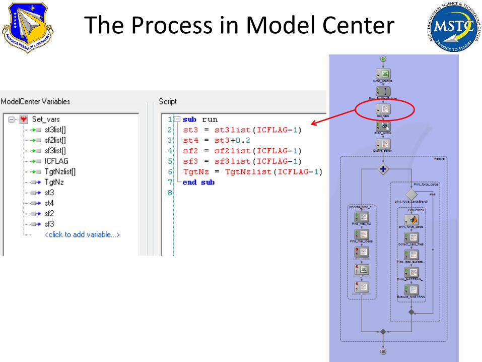
The Process in Model Center

The Process in Model Center

• StS DFS essentially adds the incremental dynamic aeroelastic loads to the wind tunnel measured loads with or without static aeroelastic correction.
• StS DFS can be modified to import the flight recorded aircraft states for generating loads spectrums of individual fleet members.
• StS DFS can identify previously undefined high stress monitoring areas (hot spots).
• The loads spectrum generated by StS DFS can be used to perform ground fatigue tests or fatigue analysis to identify the residual fatigue life of aircrafts.
Conclusions

Demo