
Switching techniques in data acquisition systems for ...
31
- 1 - Switching techniques in data acquisition systems for future experiments. M. F. Letheren CERN, Geneva, Switzerland. Abstract An overview of the current state of development of parallel event building techniques is given, with emphasis on future applications in the high rate experiments proposed at the Large Hadron Collider (LHC). The paper describes the main architectural options in parallel event builders, the proposed event building architectures for LHC experiments, and the use of standard networking protocols for event building and their limitations. The main issues around the potential use of circuit switching, message switching and packet switching techniques are examined. Results from various laboratory demonstrator systems are presented. 1 Introduction A high energy physics experiment is usually composed of several different multi-channel detectors, each of which is equipped with its own specific modular front-end and readout electronics. Whenever an event trigger occurs, readout controllers each read the data from a local group of channels and format it into an event fragment in a local front-end memory. The various event fragments belonging to an event are scattered over these front-end memories, and they must be brought together 1 before the event can be processed on-line using algorithms operating on the global event data, or before the event data can be recorded to mass storage. The process of collecting together the distributed event fragments is called event building. Figure 1(a) shows the architecture of a generic data acquisition system that includes a processor farm for on-line software triggering and uses a shared-medium interconnect to perform event building by moving event fragments from the sources (front-end buffers) into the destinations (members of the processor farm). All processors in the farm run identical algorithms and any given event is processed by just one processor. An event manager controls the allocation of each “new” event to a “free” processor. The shared-medium interconnect may be for example a bus (e.g. FASTBUS or VMEbus), a token-passing ring or an ethernet segment. A control protocol operates between the source and destination modules in order to provide such functions as the sequencing of the readout of event fragments, checking that all fragments are correctly received, and the detection and recovery from errors. Before proceeding we define parameters that we will use to characterize the event builder’s performance. The rate at which events can be built must at least match the highest expected trigger rate. Related to event building rate is throughput, the quantity of event data built per unit time. The event building latency is the delay from the trigger until the last event fragment of the event is collected; it depends mainly on the time that fragments spend queuing in various parts of the system and on software overheads in the destination. The operating load is the ratio of throughput to the nominal bandwidth offered by the event builder. The operating load is a measure of the efficiency with which the hardware is used. Note that the rate is not 1 We will not discuss an alternative approach using the Scalable Coherent Interface [1] to implement a distributed, shared-memory, memory-mapped event building architecture minimizing data movement. brought to you by CORE View metadata, citation and similar papers at core.ac.uk provided by CERN Document Server
Transcript of Switching techniques in data acquisition systems for ...

- 1 -
Switching techniques in data acquisition systems for futureexperiments.
M. F. LetherenCERN, Geneva, Switzerland.
Abstract
An overview of the current state of development of parallel event building techniques isgiven, with emphasis on future applications in the high rate experiments proposed at theLarge Hadron Collider (LHC). The paper describes the main architectural options inparallel event builders, the proposed event building architectures for LHC experiments, andthe use of standard networking protocols for event building and their limitations. The mainissues around the potential use ofcircuit switching, message switching and packetswitching techniques are examined. Results from various laboratory demonstrator systemsare presented.
1 Introduction
A high energy physics experiment is usually composed of several different multi-channeldetectors, each of which is equipped with its own specific modular front-end and readoutelectronics. Whenever an event trigger occurs, readout controllers each read the data from alocal group of channels and format it into anevent fragmentin a local front-end memory. Thevarious event fragments belonging to an event are scattered over these front-end memories, andthey must be brought together1 before the event can be processed on-line using algorithmsoperating on the global event data, or before the event data can be recorded to mass storage. Theprocess of collecting together the distributed event fragments is calledevent building.
Figure 1(a) shows the architecture of a generic data acquisition system that includes aprocessor farm for on-line software triggering and uses a shared-medium interconnect toperform event building by moving event fragments from thesources (front-end buffers) into thedestinations (members of the processor farm). All processors in the farm run identicalalgorithms and any given event is processed by just one processor. An event manager controlsthe allocation of each “new” event to a “free” processor. The shared-medium interconnect maybe for example a bus (e.g. FASTBUS or VMEbus), a token-passing ring or an ethernet segment.A control protocol operates between the source and destination modules in order to provide suchfunctions as the sequencing of the readout of event fragments, checking that all fragments arecorrectly received, and the detection and recovery from errors.
Before proceeding we define parameters that we will use to characterize the eventbuilder’s performance. Therate at which events can be built must at least match the highestexpected trigger rate. Related to event building rate is throughput, the quantity of event databuilt per unit time. Theevent building latency is the delay from the trigger until the last eventfragment of the event is collected; it depends mainly on the time that fragments spend queuingin various parts of the system and on software overheads in the destination. The operatingloadis the ratio of throughput to the nominal bandwidth offered by the event builder. The operatingload is a measure of the efficiency with which the hardware is used. Note that the rate isnot
1 We will not discuss an alternative approach using theScalable Coherent Interface [1] to implement adistributed, shared-memory, memory-mapped event building architecture minimizing data movement.
brought to you by COREView metadata, citation and similar papers at core.ac.uk
provided by CERN Document Server

- 2 -
given by the reciprocal of the latency; when sufficient memory is available in the system, highrates (or equivalently, high throughput or load) can be achieved even when latencies are long(pipeline effect).
From the point of view of processing power, the architecture can be scaled to handlearbitrarily high trigger rates by adding processors. However, the shared-medium interconnectimposes a limit to the bandwidth available for moving event fragments to the destinations. Veryhigh rate experiments require a parallel event building approach, in which events are builtconcurrently in the different destinations using a fabric of parallel interconnects betweensources and destinations. All sources need to be able to connect to all destinations andfigure 1(b) indicates how aswitching network employing acrossbar architecture can be used toachieve this with one link interface per source and per destination. The switch can beelectronically reconfigured to establish any desired pattern of parallel independent connectionsbetween N source and M destination modules. Until a path to the destination can be madeavailable, each source must queue event fragments in one of M queues corresponding to thedesired destination. Time multiplexing is used on the links to carry data from the differentqueues, while switching between different link interconnection patterns is used to route the datato the appropriate destination. A control scheme is needed to coordinate the configuration of theswitch with the time multiplexing of the data on the links. In this paper we will describeswitch-based event building using three different control schemes implementingmessageswitching, circuit switching andpacket switching.
The crossbar switch is said to benon-blocking because, from every source, one canalways allocate a path to any destination which is not already connected to another source. Thecomplexity of an N x N crossbar grows like N2, and this limits the maximum practical size of acrossbar. Large switching networks use multi-stage topologies and have a complexity thatgrows like N.logN. Depending on the operating load and the traffic patterns, they suffer to agreater or lesser extent from internal blocking. Note that even with an internally non-blocking
Trigger
Source N
Source 2
Event Manager
Source 1 Destination 1
Destination 2
Destination M
Control protocol
Control protocol
N s
ourc
es
M destinations
1
2
N
M1 2
Switch configuration& link multiplexingcontrol logic
Crossbarconfiguration
Link muxcontrol
Figure 1: (a) A generic data acquisition architecture including an on-line filteringprocessor farm and event building based on a shared-media interconnect;(b) parallel event building using a crossbar switching fabric.
Front-endchannels
Local readout Event building
(a) (b)
Crossbar switch

- 3 -
switch,output blocking can occur when multiple sources try to connect simultaneously to thesame destination.
There are many aspects to a complete data acquisition and triggering system, but thispaper limits its scope to parallel event building architectures based on switching fabrics. Wefirst give an overview of the main architectural options in parallel event builders and then wedescribe the proposed event building architectures for LHC experiments, with emphasis onperformance and other requirements. We then look at the use of standard networking protocolsfor event building and their limitations. This is followed by an overview of the issues aroundthe potential use ofcircuit switching technologies for event building. Work on the alternativeapproach of usingmessage switching technologies is then described and is followed byconsidering the application ofpacket switching andcell switching techniques.
2 Architecture Options for Parallel Event Building
2.1 Push versus Pull control protocols
The data flow control architecture can use either thepush or pull discipline. In the pushdiscipline, the event manager assigns a destination for the next event and broadcasts the eventnumber and destination identifier to all sources. The sources then send out their event fragmentsto the assigned destination. This requires a minimal protocol overhead and has potentially thehighest throughput. However, because multiple sources attempt to send their event fragmentsconcurrently, the event fragments will arrive at the destination in an indeterminate order,requiring a scatter-gather hardware feature in the interface adapter, or a more intensive activityfor buffer management and merging in the host.
One or more sources may be either “dead” or “empty” for a given event, and therefore, inthe push architecture, the destination must implement some algorithm (as part of theeventbuilding protocol) that allows it to decide when all the event fragments for an event have beenreceived. In addition, multiple sources compete for the same output and, depending on theswitching technology and the algorithm used to assign events to destinations, the result may bereduced throughput, increased event building latency, or loss of data. In section 6.2.3 we showthat these effects can be minimized by an appropriatedestination assignment algorithm, and insection 7.2.2 we show how thetraffic shaping technique can resolve these problems.
In the pull discipline the destination processor initiates the data transfer by requestingevent fragments from each of the sources in turn. The event fragments are therefore deliveredin a known, fixed sequence, and it is implicitly clear when all the event fragments have beencollected. In addition, error detection and handling are relatively straight forward. The pulldiscipline can be used to implement intelligent, selective readout, thereby reducing the amountof data moved and allowing the use of smaller and cheaper switches. The sequential pull offragments, or multicasting of requests tosmall groups of sources, avoids the congestion andblocking problems of the push architecture. The disadvantage is that the pull technique imposesa fair amount of software overhead to support the source-destination control protocols.
2.2 Event flow management algorithms
The event manager’s choice of destination for the next event may use strategies such asround-robin, random destination, least loaded processor, etc. Ideally the event manager shouldbalance the load on the members of the processor farm, but, as already mentioned, the choiceof the destination assignment algorithm can have a significant impact on the performance of theswitching fabric.
- 4 -
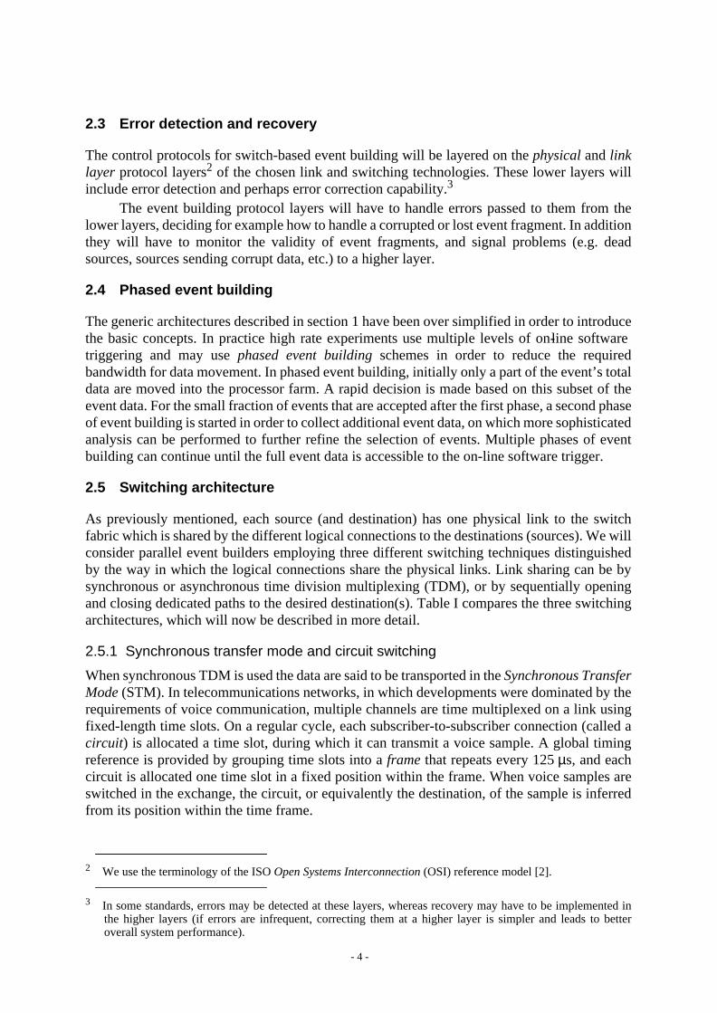
2.3 Error detection and recovery
The control protocols for switch-based event building will be layered on thephysical andlinklayer protocol layers2 of the chosen link and switching technologies. These lower layers willinclude error detection and perhaps error correction capability.3
The event building protocol layers will have to handle errors passed to them from thelower layers, deciding for example how to handle a corrupted or lost event fragment. In additionthey will have to monitor the validity of event fragments, and signal problems (e.g. deadsources, sources sending corrupt data, etc.) to a higher layer.
2.4 Phased event building
The generic architectures described in section 1 have been over simplified in order to introducethe basic concepts. In practice high rate experiments use multiple levels of on-line softwaretriggering and may usephased event building schemes in order to reduce the requiredbandwidth for data movement. In phased event building, initially only a part of the event’s totaldata are moved into the processor farm. A rapid decision is made based on this subset of theevent data. For the small fraction of events that are accepted after the first phase, a second phaseof event building is started in order to collect additional event data, on which more sophisticatedanalysis can be performed to further refine the selection of events. Multiple phases of eventbuilding can continue until the full event data is accessible to the on-line software trigger.
2.5 Switching architecture
As previously mentioned, each source (and destination) has one physical link to the switchfabric which is shared by the different logical connections to the destinations (sources). We willconsider parallel event builders employing three different switching techniques distinguishedby the way in which the logical connections share the physical links. Link sharing can be bysynchronous or asynchronous time division multiplexing (TDM), or by sequentially openingand closing dedicated paths to the desired destination(s). Table I compares the three switchingarchitectures, which will now be described in more detail.
2.5.1 Synchronous transfer mode and circuit switching
When synchronous TDM is used the data are said to be transported in theSynchronous TransferMode (STM). In telecommunications networks, in which developments were dominated by therequirements of voice communication, multiple channels are time multiplexed on a link usingfixed-length time slots. On a regular cycle, each subscriber-to-subscriber connection (called acircuit) is allocated a time slot, during which it can transmit a voice sample. A global timingreference is provided by grouping time slots into aframe that repeats every 125µs, and eachcircuit is allocated one time slot in a fixed position within the frame. When voice samples areswitched in the exchange, the circuit, or equivalently the destination, of the sample is inferredfrom its position within the time frame.
2 We use the terminology of the ISOOpen Systems Interconnection (OSI) reference model [2].
3 In some standards, errors may be detected at these layers, whereas recovery may have to be implemented inthe higher layers (if errors are infrequent, correcting them at a higher layer is simpler and leads to betteroverall system performance).

- 5 -
As an example, figure 2 shows the frame structure specified in the InternationalTelecommunication Union’s (ITU) recommendation G.703 [3] for the transmission of circuitsat the bit-rate of 34.368 Mbit/s. The frame is presented as a matrix of 59 columns (each of onebyte) and 9 rows. One byte of the matrix is reserved and, together with an additional 6 bytes,forms the so-calledpath overhead, which is used for link error signalling and “operations andmanagement” (OAM) functions. The total length of the frame is 537 bytes and it is transmittedin exactly 125µs at the bit-rate of 34.368 Mbit/s. When a time slot of length eight bits is used,the available 530 byte payload can carry 530 circuits of 64 kbit/s each.
The STM data are switched in the exchange using the so-calledcircuit switchingtechnique, whose principle is indicated in figure 3. The switch first synchronizes frames onincoming links, and then maps slots from the frames on each incoming link into new slots inframes on an outgoing link. In general, in the public switching networks the time slots used tocarry a circuit on the incoming and outgoing links are not in the same fixed position within theirrespective frames. Therefore the STM switch will be built from a combination of time slotinterchange (TSI) units and space switches, which together perform the reordering of slots in
Synchronous TDM (STM)
Asynchronous TDM (ATM)
Dedicated connection
Circuit switching
Packet switching
Message switching
Telephone switching technology;constant bit-rate traffic;equal bandwidth per circuit;concurrently active circuits.
Data network switching technology;bursty traffic;bandwidth allocated per connection;concurrently active connections.
Switching streams point-to-point;connection setup overheads;efficient for long block transfers;sequentially active connections.
Multiplexing Scheme Switching Technique Application Area and Characteristics
Table I: Traffic multiplexing schemes and their associated switching techniques.
Figure 2: The 125 µs G.703 frame structure used for synchronous transmission at 34.368 Mbit/s.
59 bytes
9 rows
FA1 FA2BIP-8TRMANRGC
Path overhead bytes
FA Frame AlignmentBIP-8 Bit Interleaved ParityTR Trail traceMA Far End Receive Fail
Far End Block ErrorPayload type
NR Network operator byteGC General Communication
channel (for maintenance)
Payload

- 6 -
the time frames and the routing of slot data from input link to output link. The TSI is essentiallya memory in which the time slots are organised into separate logical queues, that can berandomly accessed by the switch. The TSI and switch routing control information are shown intabular form in the figure. This table is set up during thesignalling protocol that establishes thecircuits between the subscribers (the call dialling process).
An important characteristic of the circuit switched technique is that it offers equalbandwidth to all circuits. Circuit switching is not well suited for supporting a mixture ofdifferent classes of services, such as computer network traffic, telephone traffic, compressedvideo, or high definition television (HDTV), each of which requires circuits with widelydifferent bandwidths (from 64 kbit/s to 140 Mbit/s). In addition computer network andcompressed video traffic are naturally bursty; circuit bandwidth is wasted when the sender issilent or not transmitting at the peak bandwidth allocated to the circuit. Such applications arebetter handled by:
2.5.2 Asynchronous transfer mode and packet switching
When the time division multiplexing of the link uses an asynchronous discipline, the data aresaid to be transported in theAsynchronous Transfer Mode (ATM).4 In this mode there is noframe to provide a global time reference. Data is transmitted in chunks calledpackets and,because there is no frame, each packet must carry with it a connection label (or source anddestination address) to identify the connection to which it belongs. The absence of a fixed frameand the fact that there is no longer a requirement to maintain global timing synchronization,means that packets can be of variable length.
4 Here the acronym ATM is used in a generic sense, and is not to be confused with the specific ATMtechnology standardized for B-ISDN and LAN switching, which is introduced later in this section.
b d c a b d c a
f e f e
ab f e ab f e
c d c d
acd
b
e
f
ef
ba
d
c
Frame
Framedelimiters
Time slot
Circuit In-link slot # Out-link slot #
a 1 1 1 5c 1 2 2 3d 1 3 2 1b 1 5 1 4e 2 1 1 1f 2 4 1 2
Figure 3: The principle of circuit switching. Time slots areswitched between input and output time slotinterchangers (TSIs) under the control of amapping table that, for each time slot in the frameof each input link, defines (i) the switchconfiguration needed to route the time slot to theappropriate output link and (2) the new time slotposition in the frame on the outgoing link.
Input TSI Output TSI
1
2
1
2
In-link &time slot
Out-link &time slot
Switchconfiguration
Controller
In-Link 1
Out-Link 1
Out-Link 2
- 7 -
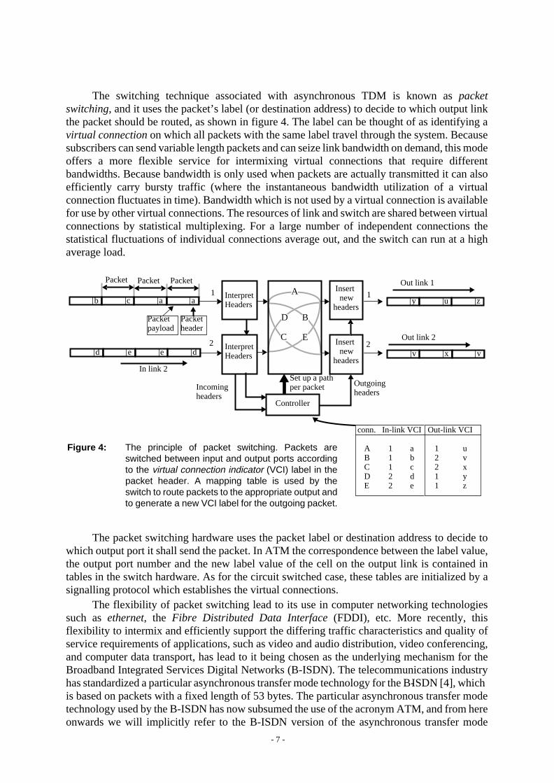
The switching technique associated with asynchronous TDM is known aspacketswitching, and it uses the packet’s label (or destination address) to decide to which output linkthe packet should be routed, as shown in figure 4. The label can be thought of as identifying avirtual connection on which all packets with the same label travel through the system. Becausesubscribers can send variable length packets and can seize link bandwidth on demand, this modeoffers a more flexible service for intermixing virtual connections that require differentbandwidths. Because bandwidth is only used when packets are actually transmitted it can alsoefficiently carry bursty traffic (where the instantaneous bandwidth utilization of a virtualconnection fluctuates in time). Bandwidth which is not used by a virtual connection is availablefor use by other virtual connections. The resources of link and switch are shared between virtualconnections by statistical multiplexing. For a large number of independent connections thestatistical fluctuations of individual connections average out, and the switch can run at a highaverage load.
The packet switching hardware uses the packet label or destination address to decide towhich output port it shall send the packet. In ATM the correspondence between the label value,the output port number and the new label value of the cell on the output link is contained intables in the switch hardware. As for the circuit switched case, these tables are initialized by asignalling protocol which establishes the virtual connections.
The flexibility of packet switching lead to its use in computer networking technologiessuch asethernet, the Fibre Distributed Data Interface (FDDI), etc. More recently, thisflexibility to intermix and efficiently support the differing traffic characteristics and quality ofservice requirements of applications, such as video and audio distribution, video conferencing,and computer data transport, has lead to it being chosen as the underlying mechanism for theBroadband Integrated Services Digital Networks (B-ISDN). The telecommunications industryhas standardized a particular asynchronous transfer mode technology for the B-ISDN [4], whichis based on packets with a fixed length of 53 bytes. The particular asynchronous transfer modetechnology used by the B-ISDN has now subsumed the use of the acronym ATM, and from hereonwards we will implicitly refer to the B-ISDN version of the asynchronous transfer mode
conn. In-link VCI Out-link VCI
A 1 a 1 uB 1 b 2 vC 1 c 2 xD 2 d 1 yE 2 e 1 z
Figure 4: The principle of packet switching. Packets areswitched between input and output ports accordingto the virtual connection indicator (VCI) label in thepacket header. A mapping table is used by theswitch to route packets to the appropriate output andto generate a new VCI label for the outgoing packet.
Packet
Packetheader
1
2
Out link 1
2
Incomingheaders
Outgoingheaders
Set up a pathper packet
Controller
Out link 2
In link 2
a
Packetpayload
ab c
ded e
Insert new
headers
Insert new
headers
1
vv x
B
C
D
E
zy u
PacketPacket
AInterpretHeaders
InterpretHeaders

- 8 -
whenever we use the acronym ATM. The 53-byte packets used for the ATM transmission andswitching are calledcells in order to differentiate them from the generic use of the term “packet”or the specific packets used at higher levels of data communications protocols. The particulartechnology of ATM switching is calledcell switching.
The basic ATM standard defined by the ITU is being adopted by the computer industryfor high speed networking, and the ATM Forum [5] is further developing the standards withemphasis on the computer industry’s requirements.
The Synchronous Digital Hierarchy (SDH) [6] and theSynchronous Optical Network(SONET) [7] are (almost) identical framing standards that have been designed to support themultiplexing of all previously defined synchronous transmission standards in a common STMframe. However, SDH and SONET also support the asynchronous TDM transport of ATM cellsby loading them into the first available position within the frame payload. The SONET / SDHstandards are widely used for transport of ATM cells at the physical layer within both thetelecommunications and computer industry. In addition, the ATM Forum has defined severalalternative physical layer transport standards for use with ATM.
2.5.3 Dedicated point-to-point links and message switching
In contrast to the circuit switching and packet switching techniques, which use time divisionmultiplexing to concurrently carry the traffic of multiple circuits (connections) over a link, themessage switching approach sets up a dedicated path between source and destination for thetime required to transmit a complete message (in our case an event fragment). Once the messagehas been transmitted the path is torn down and a new dedicated path can be set up to the nextdestination.
The delay required to set up a connection imposes a deadtime, during which no data aretransferred. As shown in figure 5, this overhead consists of one component contributed by therouting of a connection request through the switch, and a second component contributed by thedelay before the receiver signals back a connection accept. The effective throughput that can beachieved depends on the ratio of the connection set up overhead to the time required to transmitthe message.
Examples of message switching technologies, originally developed for high speedchannel connections between processors and/or peripherals, are theHigh Performance ParallelInterface (HiPPI) standard [8] and theFibre Channel [9] standard (in service class 1).
Sender Switch Receiver
Ack. connect
Con
nect
ove
rhea
d
Request connectdest. address
Send data
Drop connection
Figure 5: Message switching involves an overhead in order to set up a dedicated connection.
- 9 -
2.5.4 Signalling
In telephone or typical computer networks, asignalling protocol must be used to establish acircuit or (virtual or dedicated) connection between source and destination before data can betransferred. Signalling sets up a contract between the two connection end points (source anddestination) and the switching fabric. On the other hand, in event building the full connectivitybetween all sources and destinations is used, and no connection is dormant for long periods. Inthe circuit switched or packet switched event builder we can take advantage of this fact bydefining circuits or virtual connections which are left in place throughout the data taking run.They can be initially established either by running signalling protocols, or by adopting asystem-wide convention that allows off-line calculation and subsequent downloading of themapping tables for the switches. By using such semi-permanent circuits or virtual connectionswe avoid overheads associated with dynamic connection set up.
By contrast, in the case of event building with message switching, the use of dedicatedconnections forces a signalling protocol to be executed for every message transferred, andresults in a connection set up overhead as indicated in figure 5.
3 Proposed Architectures and Requirements for the LHC Experiments
We describe next the phased event building schemes proposed for the CMS and ATLASexperiments at the LHC, and use these to define event builder requirements.
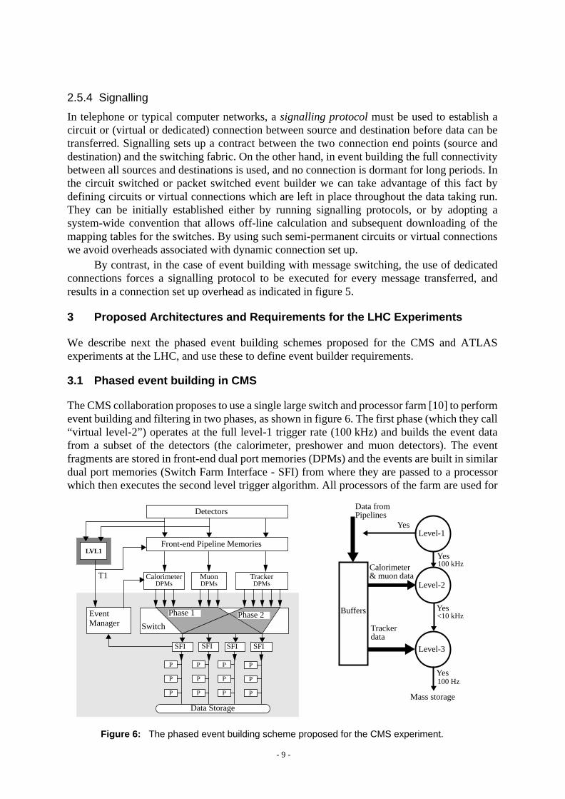
3.1 Phased event building in CMS
The CMS collaboration proposes to use a single large switch and processor farm [10] to performevent building and filtering in two phases, as shown in figure 6. The first phase (which they call“virtual level-2”) operates at the full level-1 trigger rate (100 kHz) and builds the event datafrom a subset of the detectors (the calorimeter, preshower and muon detectors). The eventfragments are stored in front-end dual port memories (DPMs) and the events are built in similardual port memories (Switch Farm Interface - SFI) from where they are passed to a processorwhich then executes the second level trigger algorithm. All processors of the farm are used for
Yes100 kHz
Trackerdata
Level-2
Level-1
Level-3
Calorimeter& muon data
Yes
Yes
Data fromPipelines
Buffers
100 Hz
Yes<10 kHz
Mass storage
Front-end Pipeline Memories
CalorimeterDPMs
MuonDPMs
TrackerDPMs
Data Storage
LVL1
P
P
P
P
P
P
P
P
P
P
P
P
Phase 1 Phase 2EventManager
SFI SFI SFI SFI
Detectors
T1
Switch
Figure 6: The phased event building scheme proposed for the CMS experiment.

- 10 -
the second level trigger. Whenever one of the processors finds an event that passes the secondlevel trigger, it initiates the second phase of event building, in which the remaining data for thatevent (from the tracker) are assembled into the SFI. Once the entire event data is present theprocessor proceeds to execute the level-3 trigger algorithms.
Note that the DPMs have to emit event fragments at the full level-1 trigger rate of100 kHz. The protocol with the event manager, the access of the appropriate event fragmentqueues, the adaptation of the data to the switch interface and the memory management of theDPM is a formidable challenge at these rates. Considerable effort is being expended on thedevelopment of programmable and hardwired DPM controllers [11].
3.2 Phased event building in ATLAS
Figure 7 shows the logical model of the ATLAS architecture [12] and the proposed eventbuilding phases. The level-1 trigger provides the level-2 trigger system with pointers to regionsof the detector containing information that fired the level-1 trigger. The “regions of interest”(RoI) pointers change from event to event; the RoIs are dynamically selected for readout by thelevel-2 trigger system; the data of each RoI is processed in a different local processor (LP) inorder to extract compact descriptions (<100 bytes) of the physicsfeatures(e.g. a shower in thecalorimeter). After the local processing step, each event’s features are sent to one of a farm ofglobal processors (GP), where a level-2 trigger decision is made. The level-2 decision may notuse the information from all detectors. Thus the level-2 system uses partial event building inlocal and global phases over the local and global networks shown in figure7. For those eventsthat pass the level-2 trigger, there follows a full event building phase for the level-3 triggersystem.
The model shown in Figure 7 is a logical model; it could be implemented in many ways,for example by using physically distinct networks and processor farms for each phase, or byhandling the three logical phases with a single farm and a single large flexible switching system.
Yes100 Hz
Mass storage
LVL1
Figure 7: The phased event building scheme proposed for the ATLAS experiment
Front-end Pipeline Memories
CalorimeterBuffers
MuonBuffers
TrackerBuffers
Local Switch
Global Switch
L3 SwitchL2Supervisor
LP LP LP LP
GP GPGP
L3Supervisor Data Storage
LVL2 LVL3
P P P
P P P
P P P
Detectors
T1
RoI
ptr
T2
Full eventdata
Level-2Local
Level-1
Level-2Global
Level-3
RoI ptr.
RoIdata
features
Yes
Yes
Data fromPipelines
Buffer
100 kHz
1 kHz

- 11 -
The average number of RoIs per event is expected to be about 5, and their selectivereadout is expected to reduce the effective level-1 trigger rate (T1) to be handled by individualfront-end buffers to approximately 10 kHz (c.f. 100 kHz in CMS), which gives more scope fordevelopment of an intelligent front-end buffer [13]. In principle, the parallel processing of RoI’salso reduces level-2 data collection and trigger processing latency with respect to the equivalentlatencies in the CMS architecture. However, given the availability of large, affordable front-endbuffer memories, this does not seem to the author to be a decisive advantage.
3.3 Requirements for event building at LHC
3.3.1 Bandwidth and latency requirements
The data acquisition systems of the LHC experiments [10, 12] are being designed to handle amaximum first level trigger rate T1 ~ 100 kHz, corresponding to operation at the nominal fullLHC luminosity of 1034 cm-2s-1. In order to estimate the bandwidth requirements for the phasedevent building system, we reproduce in table II the expected event data sizes for eachsubdetector of the CMS experiment. The tracker and pixel detector together produce the largestcontribution to event data, which is why they are not used in the virtual level-2 phase. It is(conservatively?) estimated that the virtual level-2 phase will reduce the level-1 rateT1 ~ 100 kHz to a level-2 accept rate T2 ~ 10 kHz.
Table II also shows the estimated maximum event building traffic to be handled by theCMS virtual level-2 and level-3 phases under the above assumptions. The event builder shouldsupport an aggregate throughput of ~25 GByte/s, or approximately 200 Gbit/s. In practice it isexpected to be difficult to operate a large switch above 50% of its nominal aggregate bandwidth,therefore CMS have specified a total switching bandwidth of ~ 500 Gbit/s. A suitable CMSevent builder could be implemented for example with a large switching fabric having 1000 inputand 1000 output ports, each running at the nominal standard SONET bit-rate of 622 Mbit/s.
The required aggregate event building bandwidth for ATLAS is somewhat smaller thanfor CMS, due to the selective readout of RoIs, and is estimated to be of the order 100Gbit/s.
In the CMS architecture, each of the 1000 destinations must make on average 100 level-2decisions per second, i.e. one every 10 ms. If the processing of events is overlapped with eventbuilding, the event builder must deliver a new event at each destination every 10ms on average.The latency for building an event can be longer than 10 ms if several events are concurrently
Table II: Average sub-detector event size and expected event building bandwidth contributionsfor the CMS experiment (drawn from [10]).
Sub-detector No. channels Occupancy Event sizeEvent builder bandwidth
(GByte/s)
L2 traffic L3 traffic(T1=100 kHz) (T2=10 kHz)
(%) (kByte)
PixelInner TrackerPreshowerCalorimetersMuonsL1 triggerTOTALS:
80 000 00016 000 000
512 000250 000
1 000 00010 000
~ 108
0.01 3
10 10 0.1
100-
100700100501010
~1000
--
10511
17
17----8

- 12 -
built in each destination. The upper limit of acceptable event building latency will bedetermined by the number of concurrently built events that can be supported by the switchinterface hardware and software, and not by the available buffer memory (the planned100 MByte capacity of the CMS DPMs is sufficient to buffer the full level-1 data stream for1 second). A few times 10 ms is an acceptable latency for building a single event for level-2.For level-3, acceptable event building latencies are up to a few hundred ms.
3.3.2 Other requirements
There are several important “soft” requirements to be taken into consideration. The eventbuilder must beexpandible, and exhibit favourable scaling characteristics for throughput andlatency as a function of offered load. The chosen technology should follow anopencommunications standard that will ensure plug-compatibility with equipment from differentmanufacturers, and the long term commercial availability of system components (interfaceadaptors, protocol chip sets, etc.). Ideally, the life cycle of the switch itself should match that ofthe LHC experiment.
In view of the scale of the LHC event builders, afault tolerant switch architecture wouldbe desirable, and goodoperations and management tools for monitoring of performance anderror rates, testing and fault diagnosis will be necessary. The switching fabric should supportpartitioning into individual private networks for the independent test and development ofdetectors by their dedicated teams, and it should provide the ability to spy on the data streams.
A rich range of switching technologies is currently under study as potential candidates forconstructing high rate event builders [e.g. 1, 14-17]. In this paper we select a few standardized,commercially supported technologies to illustrate the pros and cons of the three differentswitching architectures described in section 2.5.
4 Event Building using the TCP/IP Protocols
A number of experiments [18-20] are using farms of high performance UNIX workstations toperform on-line event filtering with (a possibly reduced version of) the off-line event analysissoftware. Front-end readout processors running a real time operating system assemble the eventfragments. The events are built in the UNIX workstations using a high performance networkand commercial network adaptors. The standard internet communications protocols TCP/IP,which are supported in both the UNIX operating system and the real time kernel of the front-endprocessor, are used to transmit event fragments. This approach minimizes the amount of specialhardware and protocol software development needed.
4.1 Overview of TCP/IP
Figure 8 shows the TCP/IP protocols in terms of the seven layer OSI protocol referencemodel [2]. The OSI physical and link layers implement the underlying networktechnology-dependent functions that handle the transmission of data in blocks or packets. TheInternet Protocol (IP) corresponds to the OSInetwork layer; it hides the underlying technologyfrom the higher levels and guarantees interworking between networks based on differenttechnologies. The IP layer forwards data in IP packets (length up to 64kByte) and fragmentsthe IP packet into the technology-dependent block or packet formats used at the link layer. IPprovides a connectionless service, i.e. it does not open a connection with the destination whensending the packet, and it provides no end-to-end reliability functions or flow control.

- 13 -
The Transmission Control Protocol (TCP) is layered on IP and corresponds to the OSItransport layer. It provides a connection-oriented service by supporting virtual connectionsbetween a source application and a destination application. The connection must be set upbefore messages can be exchanged. TCP ensures reliable, in-order delivery with error detectionand packet re-transmission after acknowledgment timeouts. A sliding window data flowscheme increases throughput on long connections by allowing the sender to transmit aheadwithout waiting for acknowledgement.
4.2 Event building with TCP/IP
The UNIX operating system allows interprocess communication over TCP/IP via a de factostandard set of system calls known as thesockets interface. The sockets interface can be usedto transfer event fragments between the front-end processors (running a UNIX-like real timeoperating system with support for TCP/IP sockets) and the UNIX host in which the events areto be built and filtered.
The use of TCP/IP for event building appears attractive because it ensures manufacturerand technology independence, as well as providing “for free” many important features (errorchecking, re-transmission etc.) that would otherwise have to be developed by the DAQ systemsdesigner. However, TCP/IP implementations may not be optimally layered on any giventechnology, and the fact that they are accessed via operating system calls means thatperformance is probably limited by operating system overheads and the copying of data buffersbetween user-space and kernel-space. An additional penalty in using TCP/IP for event buildingis that the IP layer is largely redundant because its primary function (providing interworking inan inhomogeneous network) is not required. In addition, although TCP provides flow controlon each connection, it cannot provide the flow control that is needed to manage congestionwhen independent TCP/IP connections concurrently send traffic to the same output port. Suchcongestion must be resolved by the network hardware or minimized by the system designerapplying atraffic shaping technique, as we will describe in section 7.2.2.
OSI Physical Layer
OSI Link Layer
IP
TCP
(X-windows, NFS, event building)
Socketsinterface
Connectionless internet routingand IP packet fragmentation
Figure 8: The TCP/IP protocol layers provide independence from underlying networktechnology and reliable connection-oriented data exchange
Source port
Window sizeUrgent pointer
Options Padding
Acknowledgement number
Destination portSequence number
offset
0 3 9 15 23 31
ver.
Source addressDestination address
Options Padding
header checksum
Packet lengthFragment offsetIdentification
len. service type
TransportTime to live
Payload
0 3 7 15 18 23 31
64
kByt
e m
axim
um
Checksumresrvd
IP Packet
TCP protocol header
Network layer
Transport layer
Connection-oriented, reliableinter-process message exchange
APPLICATIONS LAYERS
- 14 -
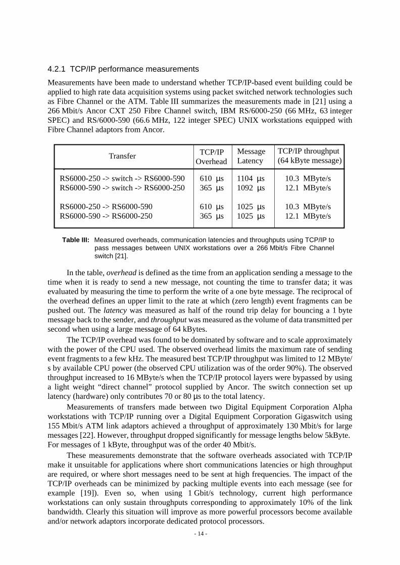
4.2.1 TCP/IP performance measurements
Measurements have been made to understand whether TCP/IP-based event building could beapplied to high rate data acquisition systems using packet switched network technologies suchas Fibre Channel or the ATM. Table III summarizes the measurements made in [21] using a266 Mbit/s Ancor CXT 250 Fibre Channel switch, IBM RS/6000-250 (66 MHz, 63 integerSPEC) and RS/6000-590 (66.6 MHz, 122 integer SPEC) UNIX workstations equipped withFibre Channel adaptors from Ancor.
In the table,overhead is defined as the time from an application sending a message to thetime when it is ready to send a new message, not counting the time to transfer data; it wasevaluated by measuring the time to perform the write of a one byte message. The reciprocal ofthe overhead defines an upper limit to the rate at which (zero length) event fragments can bepushed out. Thelatency was measured as half of the round trip delay for bouncing a 1 bytemessage back to the sender, andthroughput was measured as the volume of data transmitted persecond when using a large message of 64 kBytes.
The TCP/IP overhead was found to be dominated by software and to scale approximatelywith the power of the CPU used. The observed overhead limits the maximum rate of sendingevent fragments to a few kHz. The measured best TCP/IP throughput was limited to 12 MByte/s by available CPU power (the observed CPU utilization was of the order 90%). The observedthroughput increased to 16 MByte/s when the TCP/IP protocol layers were bypassed by usinga light weight “direct channel” protocol supplied by Ancor. The switch connection set uplatency (hardware) only contributes 70 or 80µs to the total latency.
Measurements of transfers made between two Digital Equipment Corporation Alphaworkstations with TCP/IP running over a Digital Equipment Corporation Gigaswitch using155 Mbit/s ATM link adaptors achieved a throughput of approximately 130 Mbit/s for largemessages [22]. However, throughput dropped significantly for message lengths below 5kByte.For messages of 1 kByte, throughput was of the order 40 Mbit/s.
These measurements demonstrate that the software overheads associated with TCP/IPmake it unsuitable for applications where short communications latencies or high throughputare required, or where short messages need to be sent at high frequencies. The impact of theTCP/IP overheads can be minimized by packing multiple events into each message (see forexample [19]). Even so, when using 1 Gbit/s technology, current high performanceworkstations can only sustain throughputs corresponding to approximately 10% of the linkbandwidth. Clearly this situation will improve as more powerful processors become availableand/or network adaptors incorporate dedicated protocol processors.
Table III: Measured overheads, communication latencies and throughputs using TCP/IP topass messages between UNIX workstations over a 266 Mbit/s Fibre Channelswitch [21].
RS6000-250 -> switch -> RS6000-590RS6000-590 -> switch -> RS6000-250
RS6000-250 -> RS6000-590RS6000-590 -> RS6000-250
610 µs365 µs
610 µs365 µs
1104 µs1092 µs
1025 µs1025 µs
10.3 MByte/s12.1 MByte/s
10.3 MByte/s12.1 MByte/s
Transfer TCP/IPOverhead
MessageLatency
TCP/IP throughput(64 kByte message)

- 15 -
In summary, the poor performance of TCP/IP with small packet lengths and theCPU-limited throughput obtained with larger packets make it unsuitable for high rateexperiments such as ATLAS and CMS. However, TCP/IP could find application in theALICE [23] heavy ion collider experiment, where the event rate is expected to be~50 Hz andthe event size around 20 MByte. E.g. by choosing a 128 x 128 Fibre Channel switch with linkspeeds of 266 Mbit/s, and running TCP/IP on ~100 MIPS processors, we would perform eventbuilding with average fragment sizes of ~200 kByte. Under these conditions TCP/IP softwareoverheads would be insignificant and one should be able to achieve approximately 40% load onthe switch. In pp-collider operation the ALICE event fragments would be of size ~200 Byte andthe event rate around 500 Hz, which is low enough that TCP/IP overheads would not limitthroughput.
High performance event building with single events requires the elimination of operatingsystem overheads and the layering of event building protocols directly on the network layer.
5 Parallel Event Building using Circuit Switching
The adaptation of the telephone circuit switching technique described in section 2.5.1 to parallelevent building was first reported in [24]. An N x N non-blocking crossbar switch was used, andthe input and output time slot interchangers shown in figure 3 were implemented by dual portedmemories (DPM). As indicated in figure 9(a), each input DPM contained a logical queue foreach destination, into which were placed the event fragments to be sent to that destination. Eachdestination DPM contained a logical queue per source, in which the event fragments comingfrom that source were assembled. A global control scheme defines the time slots andsynchronizes the configuration of the switch with the enabling of the appropriate queues in thesource, and destination modules. Figure 9(b) indicates how the controller globally orchestratesthe set up and tear down of connections in successive time slots, so that no two sourcessimultaneously connect to the same destination, and all sources regularly connect to alldestinations in a cycle (corresponding to the length of the time slot frame). Figure9(c) showshow, using a round-robin destination assignment algorithm, successive events can be built insuccessive output DPMs.
This simplebarrel shifter scheme avoids output blocking and is very efficient when allevent fragments have equal size and the time slot corresponds to the transmission time of oneevent fragment; in this case one complete event finishes per time slot. The throughput of theevent builder scales linearly with the size of the crossbar switch. However, when event fragmentsizes are variable, bandwidth efficiency drops because time slots are only partially filled.
AT KEK, a custom built barrel shifter event builder is being developed for possible usein a B-physics experiment [25]. High bandwidth efficiency is maintained by performingconcurrent building of multiple events in each destination. As indicated in figure9(d), when asource has finished transmitting the current event fragment, it fills the remainder of the time slotby starting transmission of the next event fragment in the currently selected queue. The optimalchoice of time slot size [26] was found to be equal to the average event fragment size (largertime slots increased the required queue lengths in source and destination, while smaller timeslots increased the impact of overheads associated with switching between time slot states).
6 Parallel Event Builders based on Message Switching
6.1 Event building with transputers
A good example of the message switching approach is provided by event building for the

- 16 -
level-3 trigger farm in the Zeus experiment [27]. The Zeus event builder is constructed fromT800 transputer-based modules and uses a custom made 64 x 64 crossbar switch to build eventsfrom 17 sources into 6 destinations. Each source has 3 links to the switch and each destinationhas 8 links to the switch. Links are based on the T800 transputer’s serial link (nominalthroughput 20 Mbit/s) and the switch is built from four C004 32 x 32 crossbar switch chips.Source and destination modules were constructed using T800 transputers and triple-portedmemory to hold the event fragments and the built events. The software in the transputers runsin stand-alone mode (no operating system).
A router and controller module, based on a transputer, runs software that allocates eventsto the least busy destinations. As soon as an event fragment becomes available in the 3-portmemory of a source, the controller module is requested to set up a connection to the allocateddestination via the crossbar. The event fragment is transferred using the T800 link protocol andthen the connection is released. Since sources make their requests asynchronously, outputblocking can occur if a source tries to connect to a destination that is already connected toanother source. In that case the connection request is queued until the output becomes available.The T800 link throughput is limited to 600 kByte/s by the delay of the handshaking protocoloperating over the 90 m of cable between the source and destination modules. The event builder
Figure 9: Event building with a simple synchronous circuit switched barrel shifter; (a) source anddestination queues; (b) switch configurations in successive time slots; (c) fragmentsequencing on the links for constant sized fragments, one event built per destination; (d)fragment sequencing for variable sized fragments, multiple events built per destination.
D0
D1
D2
S0
S1
S2
Controller Select Dst.queues
Select Src.queues Configure
switch
1
1
2
1
2
3
2
3
4
3
4
5
4
5
6
5
6
7
6
7
8
D0
D1
D2
events 1, 4, 7,.....
events 2, 5, 8,.....
events 3, 6, 9,.....
1
3
237
5D0
D1
D2
events 1, 4, 7, 10, 13.....
events 2, 5, 8, 11, 14.....
events 3, 6, 9, 12, 15.....
S0
S1
S2
D0
D1
D2
S0
S1
S2
D0
D1
D2
S0
S1
S2
D0
D1
D2
Timeslots
4
14
14
5
25
25
69
36
6
10
710
47
811
8
811
12 9
12 9
612 91013
1316
1114
(a) (b)
(c)
(d)

- 17 -
can sustain an aggregate bandwidth of 24 MByte/s, which is sufficient to meet the Zeus designgoal of handling at least 100 events/s of average size 150 kByte.
The transputer architecture offers an efficient integration of distributed multi-processingand interprocess communication (the most recent transputer technology uses packet switching)that makes it particularly suitable for building homogeneous, scalable data acquisition systems[28, 29]. The construction and evaluation, for event building applications, of a large highperformance packet switch based on OMI/HIC link and switching technology [30] is beingcarried out at CERN [17].
6.2 Parallel message switched event building with HiPPI and Fibre Channel
A similar approach to that adopted for the Zeus event builder could be taken with commercialHiPPI or Fibre Channel (class 1) switches. Both of these technologies use message switchingby including, at the head of the bit stream sent over the link, information which is interceptedby the switch and used to set up dedicated, full bandwidth connections5.
6.2.1 HiPPI technology
HiPPI was originally developed as a point-to-point simplex (unidirectional) connectiontechnology for high speed data transfer between mainframes and peripherals using a 32-bit widedata path (copper cable) and a 25 MHz clock, resulting in a bandwidth of 800 Mbit/s. HiPPIsender and receiver use a simple connection set up protocol based on a connection REQUESTline, asserted by the sender, and a CONNECT acknowledge line, which is asserted by thereceiver if it accepts the connection request. Once the connection is established, one or morevariable lengthpackets (the HiPPI packet isnot a packet in the sense of packet switchingbecause it contains no label or address) can be sent. The HiPPI packets are broken down intobursts of 1024 bytes. A credit-based flow control mechanism is supported in which the receivergives a number of “credits’” to the sender by pulsing a READY line (one credit per pulse). Thesender may send one burst per credit until it has exhausted its supply of credits. The connectionis broken either by the sender dropping its REQUEST line or the receiver dropping itsCONNECT line. Byte parity is used on the datapath and a checkword follows each burst.
HiPPI has been extended to support message switching by augmenting the connection setup protocol with the transmission of a 4-byte I-field. The I-field is used by a switch to establisha path to the receiver, which can then issue CONNECT acknowledge. If the connection requestcannot be routed to the destination, either because the switch’s output port is already occupiedor because of internal blocking in the switch, the sender can wait for the connection to beestablished, or it can drop the request (and possibly try to connect to a different receiver). HiPPIis a very simple protocol which suffers very little throughput overhead caused by header/trailerinformation. Typical connection set up overheads are ~ 1µs and have little impact on effectivethroughput, even for short messages and fast switching rates.
5 Often HiPPI and Fibre Channel (class 1) are referred to as circuit switched technologies because, during thelifetime of a connection, an unbroken chain of dedicated links is reserved between source and destination totransmit, at full speed, the data associated with the connection; there is no multiplexing on the links of datafrom other connections during the lifetime of the connection. This technique is equivalent to the earlydedicated circuit switching performed in telephone exchanges. In this paper we prefer to use the term messageswitching in order to draw a distinction with the synchronous TDM and switching techniques used in moderntelephone exchanges (as previously described in section 2.5.1).
- 18 -
6.2.2 Fibre Channel technology
The Fibre Channel protocol, as its name implies, was originally developed as a highperformance full-duplex switched interconnect technology for communicating large blocks ofdata at high speed between processors and peripherals. However, the standard was laterextended to support general purpose packet switched networking. The Fibre Channelstandard [9] defines five protocol layers (FC-0 through FC-4).
The FC-0 layer defines the physical media, connectors, and standard bit-rates to be usedon Fibre Channel links, which always consist of a pair of fibres/wires (one in each direction).The standard bit-rates are 132.8, 265.6, 531.25 and 1062.5 Mbit/s, and are supported by mediaranging from shielded twisted pairs, through coax, multimode and monomode optical fibre.Fibre Channel switches available today operate at 266 Mbit/s; 1 Gbit/s switches are underdevelopment.
The FC-1 layer defines clock and data encoding in the serial bit stream, with detection oftransmission errors. The method used is called 8B/10B because 8-bits of parallel data areconverted into 10 bits in the serial stream.
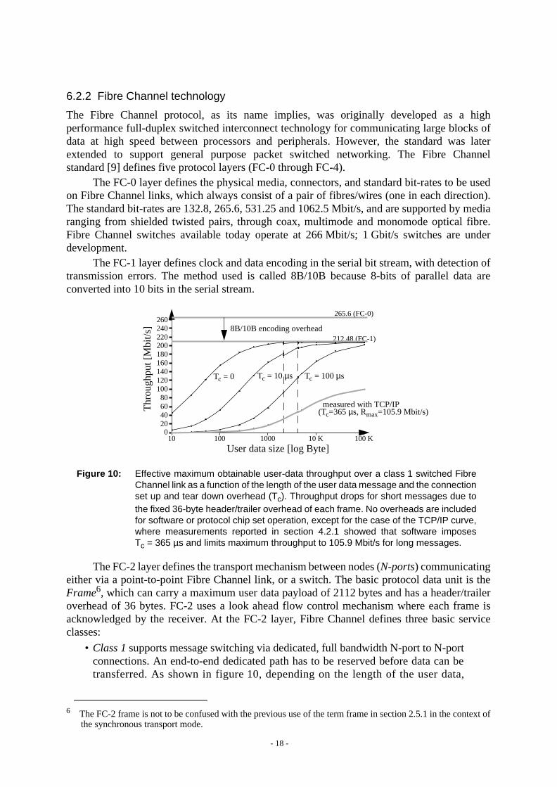
The FC-2 layer defines the transport mechanism between nodes (N-ports) communicatingeither via a point-to-point Fibre Channel link, or a switch. The basic protocol data unit is theFrame6, which can carry a maximum user data payload of 2112 bytes and has a header/traileroverhead of 36 bytes. FC-2 uses a look ahead flow control mechanism where each frame isacknowledged by the receiver. At the FC-2 layer, Fibre Channel defines three basic serviceclasses:
• Class 1 supports message switching via dedicated, full bandwidth N-port to N-portconnections. An end-to-end dedicated path has to be reserved before data can betransferred. As shown in figure 10, depending on the length of the user data,
6 The FC-2 frame is not to be confused with the previous use of the term frame in section 2.5.1 in the context ofthe synchronous transport mode.
Figure 10: Effective maximum obtainable user-data throughput over a class 1 switched FibreChannel link as a function of the length of the user data message and the connectionset up and tear down overhead (Tc). Throughput drops for short messages due tothe fixed 36-byte header/trailer overhead of each frame. No overheads are includedfor software or protocol chip set operation, except for the case of the TCP/IP curve,where measurements reported in section 4.2.1 showed that software imposesTc = 365 µs and limits maximum throughput to 105.9 Mbit/s for long messages.
10 100 1000 10 K 100 K0
20406080
100120140160180
Thr
ough
put [
Mbi
t/s]
200212.48 (FC-1)
8B/10B encoding overhead
User data size [log Byte]
Tc = 0 Tc = 10µs Tc = 100µs
220240260
265.6 (FC-0)
measured with TCP/IP(Tc=365µs, Rmax=105.9 Mbit/s)

- 19 -
connection set up and tear down overhead can significantly impact effectivethroughput. Class 1 is optimized for the fast transport of large blocks of data.
• Class 2 and Class 3 support the packet switching approach by providing aconnectionless frame switched service. The main difference between classes2 and3 is that class 2 guarantees delivery and provides acknowledgment of delivery (orin the case of congestion in the switch, returns abusystatus so that the sender canretry), whereas class 3 provides no acknowledgement. Unlike class 1, there is noconnection set up, and therefore no connection overhead.The FC-3 layer defines functions that involve multiple N-ports, such as striping
(increasing throughput by the use of multiple parallel N-port to N-port links for one logicalconnection) and multicasting. We will not describe the FC-4 layer which defines mappings ofcertain standard upper layer channel and networking protocols onto the underlying layers.
6.2.3 HiPPI event building tests
High rate, parallel event building with the message switching approach has been demonstratedin the VME environment using the HiPPI technology [15]. The demonstrator, shown inFigure 11, consisted of a non-blocking 8 x 8 HiPPI switch, three VME-HiPPI interface modules[31] acting as sources with three more as destinations, and a RAID [32] VME master running aUNIX-like real time operating system.
The VME HiPPI source and destination modules include a 25 MHz RISC processor anda HiPPI link interface based on commercial chip sets. Stand-alone firmware running on theRISC implements the primitive operations needed to send and receive data over the HiPPI links.TheSrc tasks running on the RAID use the source and destination modules as HiPPI I/O servers.TheGen task, running on the RAID, generates event fragment sizes for the sources, and theCtrltask assigns destinations and implements different event building data flow control scenarios;one “push” and two “pull”. Client-server communication was via the VME bus; because oflimited VMEbus bandwidth and the use of only one RAID, no event data was generated in theRAID or copied across VME into the sources; therefore the sources sent event fragments of thesize generated in the RAID, but containing null data.
Figure 11: (a) Software and hardware components of the RD13 VME HiPPI-based eventbuilder test bench; (b) the “push” and “pull” event building data flow scenarios.
(a) (b)
HiPPI/SSrc
SrcReadyMultiIntFlag
PUSH
HiPPI/SSrc
DstReadyMultiIntFlag
PULL
HiPPI/D
Gen
Src
Src
Src
Ctrl
Src
Src
Src
Dst
Dst
Dst
RAID Software HiPPI/SFirmware
HiPPI/DFirmware
HiPPIswitch

- 20 -
The minimum latency for a source to establish a connection and start data transfer wasmeasured as ~50µs and was dominated by the firmware overhead (the overhead for connectionset up by the switch is less than 1µs). Connection requests were queued if an output port wasblocked by an already established connection. When all event fragments were of the same sizeand events were allocated to destinations in a round robin schedule, the aggregate throughputof the 3 x 3 event builder saturated at 120 MByte/s for large event fragments (memory speedand system bus bandwidth of the processor in the VME-HiPPI interface modules limited thesustainable HiPPI source transmit bandwidth to a maximum of 40 MByte/s). For small eventfragments, the software and firmware overhead limits the load that can be applied to the switch.
Nevertheless, event handling rates of the order 10 kHz were achieved with event fragmentsizes of the order 100 bytes (a typical Atlas level-2 extracted “feature” size). Taking intoaccount that the RAID resources were shared by the client tasks of all the HiPPI sources anddestinations, higher performance (20-30 kHz) should be achievable by migrating the clienttasks into the RIO modules, or by using a faster processor.
When a random destination assignment algorithm was employed, or event fragment sizeswere allowed to vary following different statistical distributions, connection requests had toqueue in the switch for busy destinations to become free (blocking of switch output ports), andlower aggregate throughput resulted. More details can be found in [15].
The results confirm that this approach will be able to sustain the average rate of eventfragment emission required in the ATLAS architecture. At the same time they demonstrate theimportant effect of overheads in limiting the maximum event rate that can be handled at theLHC, where average event fragment sizes are expected to be between 100 - 1000 bytes. Theimpact of overheads can be reduced in several ways:
• use faster processors;
• eliminate operating system and interrupt overheads by writing stand-alone softwareand avoiding the use of interrupts (see for example section 7.3);
• pack multiple event fragments into a “super-fragment” and build “super-events”;
• use a custom hardware engine for the source and destination data flow control [11];
6.3 Discussion on event building with message switching technologies
The demonstrator results confirm that the performance required for the ATLAS architecture canbe achieved with existing HiPPI adaptors and firmware running on modestly powerfulprocessors. In principle, Fibre Channel class 1 could be used to perform event building in a verysimilar way. However, in comparison with the HiPPI switch used in the demonstrator, currentlyavailable Fibre Channel switches suffer from relatively large class 1 connection set up and teardown overheads (~100µs) which, as indicated in figure 10 makes them inefficient for high rateevent building with small event fragments.
If Fibre Channel switches are to be used in the CMS architecture, where event fragmentswitching must operate at 100 kHz, class 1 connection set up overheads in future 1 Gbit/sswitches need to be reduced to around 1µs, or better, to achieve efficient use of the nominalbandwidth. In view of the complexity of the Fibre Channel protocols and the fact that class1 isnot intended for sending short messages, it remains to be seen whether Fibre Channel switchmanufacturers will implement such low connection overheads. As mentioned before, a possibleway around the problem is to pack multiple event fragments to form larger messages, but thisadds additional processing overhead and latency that may not be acceptable for level-2 triggers.

- 21 -
An important question that should be answered before selecting a large messageswitching fabric (e.g. HiPPI or class 1 Fibre Channel) is whether connection set up handling iscentralized or distributed. A centralized connection handling scheme would have to queueconnection requests that arrive while it is busy handling a previous request. When theconnection requests are randomized in time but the load is heavy, or when the connectionrequests from different ports are correlated (as for example they would be if the fabric wasoperated as a barrel shifter), the queuing may lead to a much increased average connectionoverhead, which in turn would degrade event builder throughput.
An upper limit to the event rate that can be built by an N x N switch with centralized(non-pipelined) connection request servicing is given by:
R < 1 /(Tc * N) (1)
where Tc = connection set up latency measured when the queue for connection set up requestsis empty; e.g. for a switch using centralized connection handling with Tc = 1 µs and N = 256,we find a maximum event building rate of only 3.9 kHz.
Currently available Fibre Channel switches [33, 34] have been measured to haveTc ~ 50 - 100µs, and they probably use a centralized software-driven connection set upmechanism; they are therefore likely to be far from achieving the required 100kHzperformance. However, no measurements have been made on existing Fibre Channel switchesto determine the maximumaggregate connect request rate that they can handle. The requirementfor partitioning of the data acquisition system has lead to the proposal to use multiple, small,independent switches in ATLAS [16].
However, because very large commercial switches are not available, a large switch (e.g.for the CMS architecture) would have to be built by cascading smaller ones. A largenon-blocking switch can be constructed using a multi-stageClos network of smallernon-blocking switches. Figure 12(a) shows a two stage delta network which is blocking (asshown by the competing connections in bold). In the Clos network we add a third stage ofswitching to provide alternative paths and so make the network non-blocking as shown infigure 12(b).
The Clos network approach has been proposed [35] as a means of building large FibreChannel event builders for the LHC using the existing commercial switches (which typicallyhave up to 64 ports). With this approach the bottleneck for connection request handling is
Figure 12: (a) a two-stage network suffers from blocking whenever connections compete forthe same internal link; (b) the 3-stage Clos network is non-blocking.
(a) (b)

- 22 -
partially solved also, because individual switches do not have to handle the aggregateconnection request rate of the whole event builder. On the other hand the connection set upprocess becomes more complex because individual switches need to communicate with eachother in order to find a free path through the 3-stage network. The switch manufacturer offersconnection set up software which allows this to be done with a latency which is just three timesthe latency of one stage. The complexity of multi-stage connection management suggests thatit will continue to be implemented (mainly) in software in the future, implying that a centralized(or not fully distributed) mechanism will be used in each component switch, thereby limitingthe ability to handle high trigger rates.
In short, if a message switching approach is to be used for event building, it will beimportant to select a technology and a switch architecture employing a very low latency,distributed connection set up mechanism. The issues around the cascading of HiPPI or FibreChannel switches in event builders need more study.
7 Parallel Event Building using Packet Switching
As explained in sections 2.5.2 and 2.5.4, a packet switching technology allows the use ofsemi-permanent virtual connections (SPVCs) to provide bandwidth on demand. Figure13shows how an event builder could be constructed in which SPVCs are defined at the start of adata taking run to fully interconnect all source and destination modules. Once created, theseSPVCs would remain available until the end of the run. Since the SPVCs provide all requiredconnectivity, the dynamic set up of connections and the associated overhead that was necessaryfor message switching is now eliminated. Fibre Channel class 2 or ATM cell switching are twopossible technologies that could be used in this way. However, to the author’s knowledge, thereis no native class 2 Fibre Channel switch presently available. We will illustrate the approachusing ATM cell switching.
7.1 The B-ISDN ATM protocols
The asynchronous transfer mode using 53-byte fixed-length cells (as introduced in section2.5.2) has been adopted by the International Telecommunications Union (ITU) as theunderlying packet switching technology to integrate all telecommunications services andspecialized networks into one common, world-wide infrastructure, known as the BroadbandIntegrated Digital Services Network (B-ISDN). The ITU’s B-ISDN ATM standards [4] define
Figure 13: An event builder employing semi-permanent virtualconnections to fully interconnect all sources and destinations.
Sources DestinationsNetwork
S1
S2
SS
D1
D2
DD
- 23 -
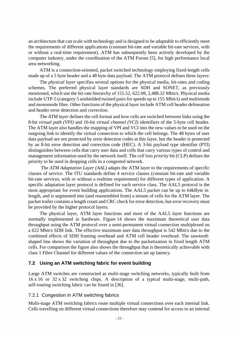
an architecture that can scale with technology and is designed to be adaptable to efficiently meetthe requirements of different applications (constant bit-rate and variable bit-rate services, withor without a real-time requirement). ATM has subsequently been actively developed by thecomputer industry, under the coordination of the ATM Forum [5], for high performance localarea networking.
ATM is a connection-oriented, packet switched technology employing fixed-length cellsmade up of a 5 byte header and a 48 byte data payload. The ATM protocol defines three layers:
Thephysical layer specifies several options for the physical media, bit-rates and codingschemes. The preferred physical layer standards are SDH and SONET, as previouslymentioned, which use the bit-rate hierarchy of 155.52, 622.08, 2,488.32 Mbit/s. Physical mediainclude UTP-5 (category 5 unshielded twisted pairs for speeds up to 155 Mbit/s) and multimodeand monomode fibre. Other functions of the physical layer include ATM cell header delineationand header error detection and correction.
TheATM layer defines the cell format and how cells are switched between links using the8-bit virtual path (VPI) and 16-bitvirtual channel (VCI) identifiers of the 5-byte cell header.The ATM layer also handles the mapping of VPI and VCI into the new values to be used on theoutgoing link to identify the virtual connection to which the cell belongs. The 48 bytes of userdata payload are not protected by error detection codes at this layer, but the header is protectedby an 8-bit error detection and correction code (HEC). A 3-bit payload type identifier (PTI)distinguishes between cells that carry user data and cells that carry various types of control andmanagement information used by the network itself. Thecell loss priority bit (CLP) defines thepriority to be used in dropping cells in a congested network.
TheATM Adaptation Layer (AAL) adapts the ATM layer to the requirements of specificclasses of service. The ITU standards define 4 service classes (constant bit-rate and variablebit-rate services, with or without a realtime requirement) for different types of application. Aspecific adaptation layer protocol is defined for each service class. The AAL5 protocol is themost appropriate for event building applications. The AAL5 packet can be up to 64kByte inlength, and is segmented into (and reassembled from) a stream of cells for the ATM layer. Thepacket trailer contains a length count and CRC check for error detection, but error recovery mustbe provided by the higher protocol layers.
The physical layer, ATM layer functions and most of the AAL5 layer functions arenormally implemented in hardware. Figure 14 shows the maximum theoretical user datathroughput using the ATM protocol over a semi-permanent virtual connection multiplexed ona 622 Mbit/s SDH link. The effective maximum user data throughput is 542 Mbit/s due to thecombined effects of SDH framing overhead and ATM cell header overhead. The saw-toothshaped line shows the variation of throughput due to the packetization in fixed length ATMcells. For comparison the figure also shows the throughput that is theoretically achievable withclass 1 Fibre Channel for different values of the connection set up latency.
7.2 Using an ATM switching fabric for event building
Large ATM switches are constructed as multi-stage switching networks, typically built from16 x 16 or 32 x 32 switching chips. A description of a typical multi-stage, multi-path,self-routing switching fabric can be found in [36].
7.2.1 Congestion in ATM switching fabrics
Multi-stage ATM switching fabrics route multiple virtual connections over each internal link.Cells travelling on different virtual connections therefore may contend for access to an internal

- 24 -
link. Contention is resolved by queuing cells within each switching chip until the internal linkis available. If the queue becomes full the switch is said to be congested.There are two courses of action that can be adopted when congestion occurs. The first is todiscard cells, the second is to use a hardware flow control protocol on the internal link to holdoff the arrival of further cells until sufficient buffer space becomes available. The strategy ofdropping cells is usually adopted in large switches designed for telecommunicationsinfrastructure, whereas some switches intended for LAN applications use the link-level flowcontrol strategy.
In telecommunications switches the aggregate traffic of a large number of independentsubscribers is assumed to be random (i.e. cells have random destinations and arrive at randomtimes). The internal buffers of the switching elements are dimensioned so that the probabilityof congestion occurring under this randomized traffic is acceptably small (typical cell lossprobabilities are 10-10 or less).
7.2.2 Traffic shaping
The natural traffic patterns generated by a “push” architecture event builder concentrate ATMcells belonging to a given event towards the single destination assigned to that event. If sourcesinject the event fragments at full link speed, the internal buffers of the switching elementsquickly fill up and acute congestion occurs.
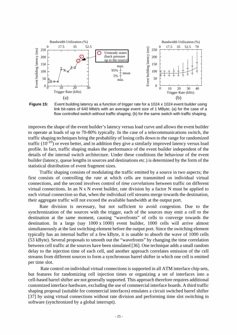
In an event builder based on the telecommunications type of switch, the congestion causessevere cell loss and the event builder is unusable. In the case of a link-level flow controlledswitch, the flow control prevents cell loss, but the simulation results in figure15(a) show thatcongestion causes the event building latency to grow non-linearly with the load on the switch[14]. When the switch is offered a load above a certain critical level, the throughput of thecongested switch is insufficient to handle the offered load and queue lengths in the sources growwithout limit. Better event builder performance could be achieved by minimizing congestion.
Internal congestion can be minimized (or even eliminated) by using the technique oftraffic shaping. As shown in figure 15(b), for the flow controlled switch, traffic shaping
Figure 14: Maximum theoretical effective user data throughput as a function of messagelength for 622 Mbit/s ATM and 1062 Mbit/s Fibre Channel class 1.
100
200
300
400
500
600
700
800
Thr
ough
put [
Mbi
t/s]
40 80 120 160 200 240 280 320
SONET/SDH overheadATM overhead
User data size [bytes]
622 Mbit/s ATM link
900
622.08 Mbit/s
542.53 Mbit/s
850 Mbit/s
Tc = 100µs
Tc = 10µsTc = 1µs
Tc = 0
1 Gbit/s Fibre Channel link
Tc = connection set up latency
8B/10B encoding overhead (FCS)
- 25 -
improves the shape of the event builder’s latency versus load curve and allows the event builderto operate at loads of up to 70-80% typically. In the case of a telecommunications switch, thetraffic shaping techniques bring the probability of losing cells down to the range for randomizedtraffic (10-10) or even better, and in addition they give a similarly improved latency versus loadprofile. In fact, traffic shaping makes the performance of the event builder independent of thedetails of the internal switch architecture. Under these conditions the behaviour of the eventbuilder (latency, queue lengths in sources and destinations etc.) is determined by the form of thestatistical distribution of event fragment sizes.
Traffic shaping consists of modulating the traffic emitted by a source in two aspects; thefirst consists of controlling therate at which cells are transmitted on individual virtualconnections, and the second involves control oftime correlations between traffic on differentvirtual connections. In an N x N event builder, rate division by a factor N must be applied toeach virtual connection so that, when the individual cell streams merge towards the destination,their aggregate traffic will not exceed the available bandwidth at the output port.
Rate division is necessary, but not sufficient to avoid congestion. Due to thesynchronization of the sources with the trigger, each of the sources may emit a cell to thedestination at the same moment, causing “wavefronts” of cells to converge towards thedestination. In a large (say 1000 x 1000) event builder, 1000 cells will arrive almostsimultaneously at the last switching element before the output port. Since the switching elementtypically has an internal buffer of a few kByte, it is unable to absorb the wave of 1000 cells(53 kByte). Several proposals to smooth out the “wavefronts” by changing the time correlationbetween cell traffic at the sources have been simulated [36]. One technique adds a small randomdelay to the injection time of each cell, and another approach correlates emission of the cellstreams from different sources to form a synchronous barrel shifter in which one cell is emittedper time slot.
Rate control on individual virtual connections is supported in all ATM interface chip sets,but features for randomizing cell injection times or organizing a set of interfaces into acell-based barrel shifter are not generally supported. This approach therefore requires additionalcustomized interface hardware, excluding the use of commercial interface boards. A third trafficshaping proposal (suitable for commercial interfaces) emulates a circuit switched barrel shifter[37] by using virtual connections without rate division and performing time slot switching insoftware (synchronized by a global interrupt).
0 10 20 30 40Trigger Rate (kHz)
0
50
100
150
200
250
Eve
nt b
uild
ing
late
ncy
(ms)
Bandwidth Utilization (%)17.5 35 52.50 70
0 10 20 30Trigger Rate (kHz)
0
50
100
150
200
250
Eve
nt b
uild
ing
late
ncy
(ms) 17.5 35 52.50
Bandwidth Utilization (%)
Unsteady states
mean95%
5%min.
max.
(back pressureup to the source)
Figure 15: Event building latency as a function of trigger rate for a 1024 x 1024 event builder usinglink bit-rates of 640 Mbit/s with an average event size of 1 MByte; (a) for the case of aflow controlled switch without traffic shaping; (b) for the same switch with traffic shaping.
(a) (b)

- 26 -
Simulation of a “pull” strategy event builder, based a single flow controlled ATM switchused to handle both the level-2 and level-3 traffic in ATLAS has given good results [38].Because of the local/global level-2 architecture the level-2 traffic can be handled, withacceptable latencies up to the full 100 kHz level-1 rate, without requiring the use of trafficshaping. For the level-3 traffic it was found to be sufficient to apply traffic shaping based onrate division only (which is simple to implement).
Another traffic shaping scheme chains the emission of event fragments from sources bycirculating a “send event fragment” token among the sources [19]. Sources only transmit thecorresponding event’s fragment when they have the token. Several tokens can be in circulationso that events can be built concurrently in different destinations.
7.3 An ATM-based event building demonstrator
Figure 16 shows a VME-based parallel event building demonstrator based on a 8-port,155 Mbit/s ATM switch [39] of the telecommunications type (no link-level flow control).Custom-designed VME-ATM interface modules [40] are used as sources and destinations.They are based on a commercial RISC I/O (RIO) VME board [41], on which the AAL5, ATMand physical layers of the protocol are implemented with commercial chip sets [42, 43]. Theevent building protocol layers are implemented in software in the on-board RISC. The physicallayer protocol used by the switch is the 155 Mbit/s SDH protocol over monomode fibre.
A logic state analyser and a broadband tester [44] are used for debugging, analysis andperformance measurements. In order to be able to load the switch with traffic on multiple inputs,a number of low cost ATM data generator [45] modules, controlled by a personal computer,have been constructed. The data generator is a memory in which any desired pattern of cells canbe loaded and sent out via a physical layer interface. The desired cell pattern is calculatedoff-line and downloaded to the data generator.
7.3.1 Event building protocols
Figure 17 shows the event building protocol stacks in source and destination. The eventbuilding software is implemented in two layers; the upperevent layer is technology independentand adapted to the underlying ATM technology by theevent fragment layer. The software runson the 25 MHz RISC processor and is layered directly onto the chipset implementations of theAAL5, ATM and SDH physical layers. For performance the software is implemented withoutoperating system and uses semaphore polling in preference to interrupts (interrupts are only
source 1
trigger gen.
logic analyser
event building latencymeasurement
start stop
Data generators
RIO/ATMinterface
Broadbandtester
RIO/ATMinterface
PC
ATM Switch
Figure 16: The ATM-based event building demonstrator.

- 27 -
used for error conditions). Because the software is distributed, its performance scales to verylarge event builder systems.
In the source (destination), the event fragment layer performs fragmentation (reassembly)of event fragments into (from) AAL5 packets. In order to minimize the required receive bufferspace allocation in the destinations, the length of theAAL5 packets used can be chosen close tothe average event fragment size (up to the 64 kByte limit supported by the ATM standard). Inthe destination, the event layer reassembles events from the received fragments. A number ofalgorithms for detection of event completion have been proposed [46]. The event completionalgorithm used to make the measurements reported in the next section was based on the timeoutprinciple.
7.3.2 Performance measurements
Figure 18(a) shows the measured maximum output of a source when pushing out eventfragments with the software described above. The dotted line is the measured output includingATM cell headers and incompletely used cell payloads; it drops for small event fragment sizesbecause of various hardware and software overheads [47]. The dashed line shows user datathroughput, and the solid line shows the maximum frequency of emitting event fragments. Thesource software could support high trigger rates (~80 kHz) with small event fragments(< 2 cells), but software overheads limit the efficiency of utilization of the bandwidth (~25%)in this case.
Event layer
Event fragment layer
AAL5 layer
ATM layer
Physical layer
Sof
twar
eH
ardw
are
Network
Destination assignment
VCI assignmentSAR queue
Assignment of event fragments
Event building completion
Reassembly of event fragments
Se
gm
en
tatio
n
Re
ass
em
bly
ATM cells
bit streams
(48 Bytes)
to events
Segmentation of AAL5packets (max. 64 kByte)
Reassembly of AAL5 packets(max. 64 kByte)
Figure 17: The event building software is implemented in two layersabove the hardware-supported ATM protocol stack.
(unlimited size)
0 256 512 768 1024fragment size (bytes)
0.0
20
40
60
80
100
frag
men
t rat
e (k
Hz)
50
100
150
thro
ughp
ut (
Mbi
t/s)
thro
ughp
ut (
Mbi
t/s)
0.0 256 512 768 10240.0
20
40
60
80
100
frag
men
t rat
e (k
Hz)
50
100
150
fragment size (bytes)
Figure 18: Performance measurements; (a) for the source pushing fragments at maximumspeed; (b) for the destination receiving fragments from 8 sources and building 2events simultaneously using the timeout algorithm; (c) measured event buildinglatency and rate for a 2 x 2 event builder.
(a) (b)
ATM throughput
User data
Fragment rateFragment rate
User data
ATM throughput
Eve
nt b
uild
ing
late
ncy
(µs)
EB latency (ms)
EB rate (kHz)
Eve
nt b
uild
ing
rate
(kH
z)
fragment size (bytes)0 256 512 768 1024
0
10
20
30
40
0
50
100
150
200
250
300
(c)
throughput
throughput

- 28 -
The corresponding measurements for the reception of event fragments, shown infigure 18(b), exhibit less throughput at larger event fragment sizes due to a bottleneck in thecurrent design of the receiver (which can easily be removed). The more complex receiversoftware makes a larger impact at small event fragment sizes, limiting the maximum fragmentreception rate to ~30 kHz
Figure 18(c) shows the measured event building latency and rate obtained in a 2x 2 eventbuilder in which each source sends 1 cell alternately to each destination. For small eventfragment sizes, the event building software in the destinations limits performance, while forlarger fragments it is the data transfer on the links that limits the performance. If required, higherperformance can be achieved by using faster processors, more destinations than sources, higherlink bit-rates, or collecting data from several events into super-fragments which are then usedto build super-events.
8 Conclusions
The size and required performance of the data acquisition and software triggering systems at thefuture LHC experiments exceed by far that of previous experiments. This paper has reviewedsome of the on-going R&D into technologies and techniques that appear to be suitable forparallel event building at LHC. Architectural options, such as the choice of trigger strategies andalgorithms, the use of phased event building and intelligent selective readout can reduce therequired data movement bandwidth. We have seen that, in order to use the full potential of highspeed link and switch technologies, careful attention has to be paid to details.
First, only a fraction of the link bandwidth is available to carry user data, the remainderbeing consumed by encoding schemes, and packetization overheads at each level of the protocolstack. Message switching technologies have a hardware connection set up overhead that,depending on its magnitude, may significantly impact the throughput achieved when sendingshort messages. Theaggregate connection set up performance of such switches must becarefully evaluated for the event building application envisaged (e.g. centralized handling ofconnection requests would be inappropriate for implementing a synchronous barrel shifter,where all connections must be switched simultaneously). Packet switching technologies offersemi-permanent virtual connections, which avoid the connection set up problems.
In a push architecture, the concentration of event fragments from multiple sources into thedestination leads to output blocking or internal congestion in the switch. Depending on thetechnology, the result is either that throughput is reduced and event building latency increased,or that data are discarded. These problems can be circumvented by an appropriate choice ofdestination assignment algorithm and by using traffic shaping. The traffic shaping technique ismandatory when using an ATM switch without flow control, but it is also beneficial with alltechnologies, allowing operation of large switches at high loads with still acceptable latencies.
Software overheads can easily dominate system performance and mask the advantagesof high speed link and switch hardware, as we saw from the measurements made using thestandard TCP/IP communications protocols in a UNIX operating system environment. Theperformance penalty of redundant protocol layers, unused functionality and operating systemoverheads can be avoided by developing optimized event building software layered directlyonto the network adaptor hardware. Results from HiPPI and ATM (155 Mbit/s) event buildingdemonstrator systems have shown that software-limited event building rates in the range10-30 kHz can be achieved with 25 MHz processors running software partly, or completely, instand-alone mode, and avoiding interrupts. A combination of faster processors and higher

- 29 -
throughput links (in the case of ATM) should permit still higher event building rates to beachieved.
Acknowledgements
I am most grateful to J.-P. Dufey for suggesting numerous improvements to the paper andassistance with the preparation of some of the figures. In addition, it is a pleasure to thank themany colleagues who provided me with information and/or enlightening discussions during thepreparation of this paper; D. Abbott, E. Barsotti, E. van der Bij, F. Chantemargue, S. Cittolin,M. Costa, J.-P. Dufey, T. Ferrari, G. Heyes, I. Mandjavidze, L. Mapelli, B. Martin,R. McLaren, S. Munoz, M. Nomachi, B. Segal, R. Spiwoks, A. van Praag.
References
[1] RD24 collaboration, “Application of the Scalable Coherent Interface to Data Acquisitionat LHC”, CERN / DRDC91-45, DRDC93-20, DRDC94-23 and LHCC95-42.
[2] M. Santifaller, TCP/IP and NFS; Internetworking in a UNIX Environment,Addison-Wesley (1991).
[3] International Telecommunications Union, Geneva, Switzerland,RecommendationG.703.
[4] International Telecommunications Union, Geneva, Switzerland,RecommendationsI.150, I.211, I.311, I.321, I.327, I.361, I.362, I.363, I.413, I.432, I.610.
[5] The ATM Forum, 303 Vintage Park Drive, Foster City, CA 94404, USA.World Wide Web home page: http://www.atmforum.com/
[6] International Telecommunications Union, Geneva, Switzerland,RecommendationsG.707, G.708and G.709.
[7] ANSI T1.105-1991, Digital hierarchy - Optical interface rates and formatsspecifications (SONET).
[8] ANSI X3T9.3/90-043, HiPPI Specification (1990).
[9] ANSI X3T11 committee, Fibre Channel draft proposed standard.
[10] CMS collaboration, “The Compact Muon Solenoid - Technical Proposal”,CERN / LHCC94-38, LHCC / P1, 15 December 1994.
[11] S. Cittolin (convenor), record of the LHC DAQ Workshop on FrontEnd Driver and DualPort Memories, CERN, March 29-30, 1995.
[12] ATLAS collaboration, “ATLAS - Technical Proposal for a General-Purpose ppExperiment at the Large Hadron Collider at CERN”,CERN / LHCC94-43, LHCC / P2,15 December 1994.
[13] J.-C. Brisson, O. Gachelin and M. Mur, “Front-end Intelligent Readout Memory”,private communication.
[14] RD31 collaboration, “NEBULAS: High performance data-driven event buildingarchitectures based on asynchronous self-routing packet switching networks”,CERN LHCC /95-14.
[15] RD13 collaboration, “A scalable data taking system at a test beam for LHC”,CERN LHCC95-47.
- 30 -
[16] W. Greiman et al., “Design and Simulation of Fibre Channel Based Event Builders”,Conf. record of the International Data Acquisition Conference, Fermi NationalAccelerator Laboratory, Batavia, Illinois, USA (October 26-28, 1994).
[17] R. W. Dobinson et al., “Realisation of a 1000-Node High Speed Packet SwitchingNetwork”, CERN-ECP /95-16 (30 August 1995).
[18] D.J. Abbott et al., “The CODA System and its Performance on the First On-lineExperiments at CEBAF”, presented at the Ninth Conference on Real-time ComputerApplications in Nuclear, Particle and Plasma Physics, Michigan State University, USA(May 22-25, 1995). Submitted to IEEE Trans. Nucl. Sc.
[19] D. C. Doughty et al., “Event Building Using an ATM Switching Network in the CLASDetector at CEBAF”, Conf. record of the International Data Acquisition Conference,Fermi National Accelerator Laboratory, Batavia, Illinois, USA (October 26-28, 1994).
[20] P. Sphicas, “CDF and D0 Data Acquisition Systems”, Conf. record of the InternationalData Acquisition Conference, Fermi National Accelerator Laboratory, Batavia, Illinois,USA (October 26-28, 1994).
[21] F. Chantemargue et al. (RD11 collaboration), private communication; a similar set ofmeasurements are reported in: C. Miron et al., “Fibre Channel Performances with IBMEquipment”,RD11-EAST note95-05 (June 1995).
[22] C. Battista et al., “Permanent Virtual Circuits Configuration and TCP-UDP / IPPerformance in a Local ATM Network”,INFN internal report no. 1060, submitted toComputer Networks and ISDN Systems. (http://www.infn.it/pub/CNAF/article.ps)
[23] N. Antoniu et al., “A Large Ion Collider Experiment at the CERN Large HadronCollider”, CERN LHCC /93-16, March, 1993.
[24] D. Black et al., “Results from a Data Acquisition System Prototype Project using aSwitch-based Event Builder”, Nucl. Sc. Symposium, Santa Fe, New Mexico (USA),Conf. record, Vol.2, pp. 833-837 (1991).
[25] O. Sasaki et al., “A VME Barrel Shifter System for Event Reconstruction for up to3 Gbps Signal Trains”,IEEE Trans. Nucl. Sc.,Vol. 40, No.4, pp. 603-606 (1993).
[26] Y. Nagasaka et al., “Global Traffic Control System of a Switching Network”, presentedat the Ninth Conference on Real-time Computer Applications in Nuclear, Particle andPlasma Physics, Michigan State University, USA (May 22-25, 1995). Submitted toIEEETrans. Nucl. Sc.
[27] U. Behrens et al., “The Event Builder of the ZEUS Experiment”, Conf. record of theInternational Data Acquisition Conference, Fermi National Accelerator Laboratory,Batavia, Illinois, USA (October 26-28, 1994).
[28] R. Heeley et al., “The Application of the T9000 Transputer to the CPLEAR Experimentat CERN”,CERN / ECP95-8 (30 March 1995). Submitted toNucl. Instr. and Meth.
[29] D. Francis et al., “Triggering and Event Building Results using the C104 Packet RoutingChip”, presented at the Conf. on Computing in High Energy Physics, Rio de Janeiro,Brazil, 18-22 September, 1995 (to appear in Conf. proceedings).
[30] E. Kristiansen et al., “Switches for Point-to-Point Links using OMI/HIC Technology”,Conf. record of the International Data Acquisition Conference, Fermi NationalAccelerator Laboratory, Batavia, Illinois, USA (October 26-28, 1994).
[31] A. van Praag et al., “HiPPI Developments for CERN Experiments”,IEEE Trans. Nucl.Sc., Vol 39, No.4, pp. 880-885 (1992).

- 31 -
[32] Creative Electronic Systems S.A., Geneva, Switzerland,RAID 8235 VME RISCProcessor Board User’s Manual, 1992.
[33] The CXT 250 Fibre Channel fabric, Ancor Communications Inc., Minnetonka,MN 55343 (USA).
[34] The IBM 7319 model 100 Fibre Channel Switch, IBM Corp.
[35] C. Jurgens, “Fibre Channel Switches”, Conf. record of the International Data AcquisitionConference, Fermi National Accelerator Laboratory, Batavia, Illinois, USA(October 26-28, 1994).
[36] M. Letheren et al., “An Asynchronous Data-Driven Event Building Scheme based onATM Switching Fabrics”,IEEE Trans. Nucl. Sc., Vol. 41, No.1, pp. 257-266 (1994).
[37] I. Mandjavidze, “A New Traffic Shaping Scheme: the True Barrel Shifter”,RD31 note94-03.
[38] D. Calvet et al., “A Study of Performance Issues of the ATLAS Event Selection SystemBased on an ATM Switching Network”, presented at the Ninth Conference on Real-timeComputer Applications in Nuclear, Particle and Plasma Physics, Michigan StateUniversity, USA (May 22-25, 1995). Submitted toIEEE Trans. Nucl. Sc.
[39] M. Henrion et al., “Technology, Distributed Control and Performance of a MultipathSelf-Routing Switch”, Proc. XIV Int. Switching Symposium, Yokohama, Japan, Vol.2,pp. 2-6 (Oct. 1992).
[40] L. Gustafsson et al., “A 155 Mbit/s VME to ATM Interface with Special Features forEvent Building Applications based on ATM Switching Fabrics”, Conf. record of theInternational Data Acquisition Conference, Fermi National Accelerator Laboratory,Batavia, Illinois, USA (October 26-28, 1994).
[41] Creative Electronic Systems S.A., Geneva, Switzerland,RIO 8260 and MIO 8261 RISCI/O Processors - User’s Manual, version 1.1 (March 1993).
[42] Transwitch Corp., Shelton, Connecticut, USA,SARA Chip Set - Technical manualversion 2.0 (Oct. 1992).
[43] PMC-Sierra Inc.,The PMC5345 Saturn User Network Interface Manual (May 1993).
[44] Hewlett Packard, Broadband Series Test System (1994).
[45] C. Paillard, “An STS-OC3 SONET / STM-1 SDH ATM Physical Layer Implementationand Application to an ATM Data Generator”,RD31 note95-04 (Feb. 1995).
[46] I. Mandjavidze, “Software Protocols for Event Builder Switching Networks”, Conf.record of the International Data Acquisition Conference, Fermi National AcceleratorLaboratory, Batavia, Illinois, USA (October 26-28, 1994).
[47] M. Costa et al., “An ATM-based Event Builder Test System”, presented at the FirstWorkshop on Electronics for LHC Experiments, 11-15 September 1995, Lisbon,Portugal (to appear in Conf. proceedings).


![Thyristor Switching Techniques PQS TSM[1]](https://static.fdocuments.in/doc/165x107/544c0245af7959a0438b5865/thyristor-switching-techniques-pqs-tsm1.jpg)


