Switch sensors - Legrand · Switch Sensors - 1 output ... Location of shelves, book cases, file...
16
Switch sensors Design & installation Guide PUTTING A STOP TO ENERGY WASTE
Transcript of Switch sensors - Legrand · Switch Sensors - 1 output ... Location of shelves, book cases, file...

Switch sensors Design & installation Guide
PUTTING A STOP TO ENERGY WASTE

2
SWIT
CH S
ENSO
RS |
DES
IGN
AND
INST
ALLA
TION
GUI
DE
This design and application guide will help you in selecting, laying out,
specifying, installing and commissioning a switch sensor lighting management
solution.
3Flow chart
4Dos and don’ts
5Detailed design steps for implementing
switch sensors - 1 output
6Step 1. Evaluate space characteristics
7Step 2. Match sensor technology
to application
8Step 3. Design and specify
− Select coverage patterns
− Select product features
12Step 4. Install and commission
− Select optimal mounting configuration
− Select sensor placement, installation,
and settings
14 Detailed design steps for implementing
room controller - 2 outputs
16Products selection chart
17Legrand lighting management solution
overview
CONTENTS
Legrand experts are available for design support and assistance. Do not hesitate to contact your local office.

3
SWIT
CH S
ENSO
RS |
DES
IGN
AND
INST
ALLA
TION
GUI
DE
Although there are several steps involved in implementing sensor controls
(outlined on the following pages), this flow chart offers a quick way to
determine which sensor technology is best for your application.
FLOW CHART
Other control strategiesare more appropriate.
Other control strategiesare more appropriate.
Is space usedintermittently? Are lights
left on in unoccupiedspaces?
Are there energy codecompliance requirements?
Are ceiling heights less than 4 m?
Would you like occupancy-based controls?
Does space containpartitions, large
equipment or furniture?
Does a small or morespecific area require
detection?
Yes
No
No
Does space containpartitions, large equipment
or furniture?
Is there a clear line of sight to all areas?
Ultrasonic
No
Yes
Other control strategiesare more appropriate.
No
Yes
Are there definite spaceboundaries?
Yes
Yes
No
Yes No
Is there a high volume of air flow, A/C?
Is there moving mechanical
equipment in the space?
Yes
NoYes
No
No
Can the owner choose anappropriate mounting
location away from air flow?
YesNoYes
No
Yes
No
No
PIR
Is space small or welldefined? Would installation of
additional sensors be justifiedin turns of payback?
Yes
Yes
No
Yes
PIR
PIR
PIR
DT or UltrasonicDT or Ultrasonic
DT or Ultrasonic

4
SWIT
CH S
ENSO
RS |
DES
IGN
AND
INST
ALLA
TION
GUI
DE Don’t
> Use ultrasonic sensors in spaces with heavy air flow/air conditioned
> Install ultrasonic sensors in spaces where the ceiling height exceeds 4 m
> Use PIR sensors in spaces where there are fixtures or furniture that obstruct a clear line of sight
> Install sensors within 2 to 3 metres of HVAC outlets or heating blowers
> Control emergency or exit lighting with sensors
> Install PIR sensors in spaces where there are extremely low levels of occupant motion
DOS AND DON’TS
Do
> Use ultrasonic sensors in areas screened by partitions or furniture
> Use PIR in enclosed spaces
> Create zones controlled by different sensors to manage lighting in large areas
> Use dual technology sensors for areas with very low activity levels
> Install sensors on vibration-free, stable surfaces
> Position sensors above or close to the main areas of activity in a space
> Integrate sensor use with other control methods (i.e. time scheduled control)
> Educate occupants about the new devices and what to expect
Following these rules help to ensure that the sensors work effectively,
providing comfort for occupants while saving money for the facility. Be sure
to review the following pages for detailed product selection guidance.

5
SWIT
CH S
ENSO
RS |
DES
IGN
AND
INST
ALLA
TION
GUI
DE
Switch Sensors - 1 output
DESIGN STEPS FOR IMPLEMENTING
Identifying the ideal sensor for a particular application involves the
consideration of several factors that are equally critical to an effective lighting
management solution.
Evaluate space
characteristics
Match sensor
technology
to application
Design
and specify
Install
and commission
1 2 3 4

6
SWIT
CH S
ENSO
RS &
SCS
SEN
SORS
| D
ESIG
N AN
D IN
STAL
LATI
ON G
UIDE
TIP !
Special attention should be paid to high levels of vibration and/or air flow, extreme temperature conditions, and unusually low levels of activity because these issues may help identify the best technology solution.
Room/space size and shape
Location(s) of occupant activity and non-activity
Location of walls, doors, windows and drapes
Ceiling height
Partition height and location
Location of shelves, book cases, file cabinets, and large equipment
Large objects that would block or alter a sensor’s coverage
Location of HVAC ducts and fans
Areas with available sunlight for added light level sensing
Location of desk/workspace – orientation with regards to walls, partitions and other obstacles
Space characteristics
Step 1 - Evaluate space characteristics
DESIGN STEPS FOR IMPLEMENTING ı SWITCH SENSORS
To evaluate the application’s characteristics, designers should become familiar
with:
7
SWIT
CH S
ENSO
RS |
DES
IGN
AND
INST
ALLA
TION
GUI
DE
NOTE
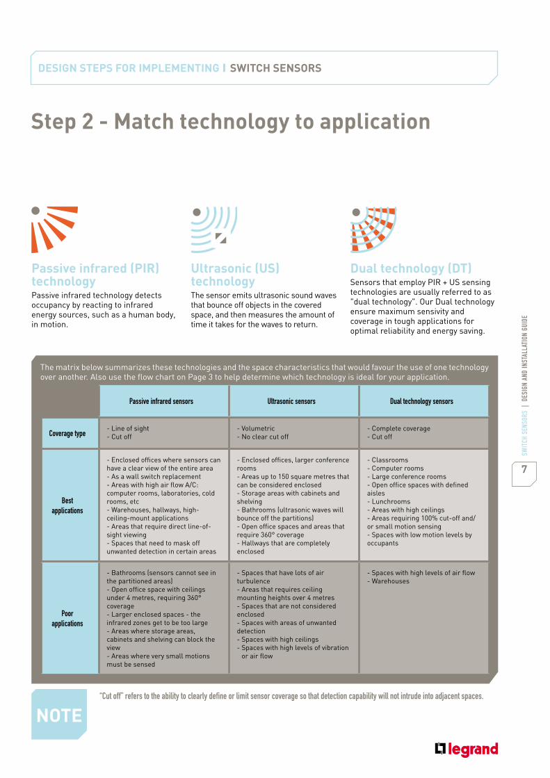
“Cut off” refers to the ability to clearly define or limit sensor coverage so that detection capability will not intrude into adjacent spaces.
The matrix below summarizes these technologies and the space characteristics that would favour the use of one technology over another. Also use the flow chart on Page 3 to help determine which technology is ideal for your application.
Passive infrared sensors Ultrasonic sensors Dual technology sensors
Coverage type- Line of sight
- Cut off
- Volumetric
- No clear cut off
- Complete coverage
- Cut off
Best applications
- Enclosed offices where sensors can
have a clear view of the entire area
- As a wall switch replacement
- Areas with high air flow A/C:
computer rooms, laboratories, cold
rooms, etc
- Warehouses, hallways, high-
ceiling-mount applications
- Areas that require direct line-of-
sight viewing
- Spaces that need to mask off
unwanted detection in certain areas
- Enclosed offices, larger conference
rooms
- Areas up to 150 square metres that
can be considered enclosed
- Storage areas with cabinets and
shelving
- Bathrooms (ultrasonic waves will
bounce off the partitions)
- Open office spaces and areas that
require 360° coverage
- Hallways that are completely
enclosed
- Classrooms
- Computer rooms
- Large conference rooms
- Open office spaces with defined
aisles
- Lunchrooms
- Areas with high ceilings
- Areas requiring 100% cut-off and/
or small motion sensing
- Spaces with low motion levels by
occupants
Poorapplications
- Bathrooms (sensors cannot see in
the partitioned areas)
- Open office space with ceilings
under 4 metres, requiring 360°
coverage
- Larger enclosed spaces - the
infrared zones get to be too large
- Areas where storage areas,
cabinets and shelving can block the
view
- Areas where very small motions
must be sensed
- Spaces that have lots of air
turbulence
- Areas that requires ceiling
mounting heights over 4 metres
- Spaces that are not considered
enclosed
- Spaces with areas of unwanted
detection
- Spaces with high ceilings
- Spaces with high levels of vibration
or air flow
- Spaces with high levels of air flow
- Warehouses
Passive infrared (PIR) technologyPassive infrared technology detects occupancy by reacting to infrared energy sources, such as a human body, in motion.
Ultrasonic (US) technologyThe sensor emits ultrasonic sound waves that bounce off objects in the covered space, and then measures the amount of time it takes for the waves to return.
Dual technology (DT)Sensors that employ PIR + US sensing technologies are usually referred to as "dual technology". Our Dual technology ensure maximum sensivity and coverage in tough applications for optimal reliability and energy saving.
Step 2 - Match technology to application
DESIGN STEPS FOR IMPLEMENTING ı SWITCH SENSORS

8
SWIT
CH S
ENSO
RS |
DES
IGN
AND
INST
ALLA
TION
GUI
DE
Step 3 - Design and specify the project
Select coverage patternsA coverage size and shapes is available for each sensor technology. While a small application is easily covered with one sensor, larger applications benefit from
grouping controlled lighting into zones (with each zone controlled by a sensor). Familiarity with these coverage patterns will help designers specify the right
product, ensuring the greatest sensor accuracy and occupant comfort. The matrix below summarizes the coverage patterns for each technology.
Technology Mounting / Shape Detection range Length (m) Coverage zone
PIR
Ceiling
mount
360° 2,5 m
4 m 45 m2
Corner
mount
180° 3 m
3 m
2,5 m
6 m
0°
45 m2
Outdoor
270° 2,5 m
16 m 180 m2
US Ceiling
mount
360° 2,5 m
6,5 m 150 m2
DUAL TECH
Ceiling
mount
360° 5,5 m2,5 m
90 m2
Corner
mount
180° 3 m
3 m
2,5 m
7,5 m
0°
90 m2
Coverage patterns
DESIGN STEPS FOR IMPLEMENTING ı SWITCH SENSORS
NOTE
For a proper light control it is recommended to place the detector at a maximum distance equal to twice the height of the window. Example: for a ceiling height of 2.8 m and a maximum window height of 2.5 m, the sensor should be placed at a maximum distance of 5 m from the window.

9
SWIT
CH S
ENSO
RS |
DES
IGN
AND
INST
ALLA
TION
GUI
DE
Example (Ultrasonic coverage)In an open, partitioned office, designers select ultrasonic sensors. To adequately cover the entire space, multiple sensors are positioned to cover a specific zone.
Example (Dual technology coverage)In a large space, such as a large hall, dual technology sensors provide coverage that suits the variable level of motion present. Here, 2 x Cat.Nos 488 06 (Dualtech ceiling mount switch sensor) with 360° coverage, welcome desk area and waiting area .
Cat.No 488 07 (PIR ceiling mount switch sensor) completes the coverage and controls the stairs area (movement area).
TIP !
TIP !
Do occupants engage in major motions, such as walking, or fine motions, such as typing or reading? Coverages change depending on motion type.
When creating zones of coverage, such as the coverage illustrated in the example above, take care to ensure that sensor coverages overlap by 20%.
10
SWIT
CH S
ENSO
RS |
DES
IGN
AND
INST
ALLA
TION
GUI
DE
Step 3 - Design and specify the project
Product features
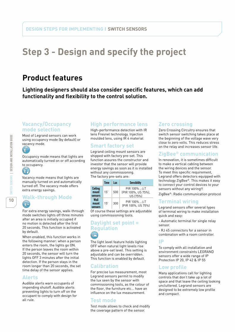
Smart factory setLegrand ceiling mount sensors are shipped with factory pre-set. This function assures the constructor and investor that the sensor will provide energy savings as soon as it is installed without any commissioning. The factory pre-sets are:
Time Lux Sensibility
Ceiling mount
sensors15’ 500
PIR 100% , tT
(PIR 100%, US 75%),
US (75%)
Wall mount
sensors15' 300
PIR 100% , tT
(PIR 100%, US 75%)
Of course these settings are adjustable using commissioning tools.
Daylight set point = Regulation
The light level feature holds lighting OFF when natural light levels rise above a pre-set level. This setting is adjustable and can be overridden. This function is enabled by default.
Low profileMany applications call for lighting controls that don’t take up a lot of space and that leave the ceiling looking uncluttered. Legrand sensors are designed to be extremely low profile and compact.
Calibration For precise lux measurement, most Legrand sensors permit to modify the lux seen by the sensor with commissioning tools, as the colour of the floor, the furniture etc... have an influence on the lux measurement.
Walk-through Mode
For extra energy savings, walk-through mode switches lights off three minutes after an area is initially occupied if no motion is detected after the first 20 seconds. This function is activated by default.
When enabled, this function works in the following manner: when a person enters the room, the lights go ON. If the person leaves the room within 20 seconds, the sensor will turn the lights OFF 3 minutes after the initial detection. If the person stays in the room longer than 20 seconds, the set time delay of the sensor applies.
AlertsAudible alerts warn occupants of impending shutoff. Audible alerts preventing lights to turn off on the occupant to comply with design for all rule.
ZigBee® communicationIn renovation, it is sometimes difficult to make a vertical cabling between the wiring devices and the sensor. To meet this specific requirement, Legrand offers detectors equipped with technology ZigBee®. This makes it easy to connect your control devices to your sensors without any wiring!!
ZigBee®: Radio communication protocol
Test modeTest mode allows to check and modify the coverage pattern of the sensor.
Terminal wiringLegrand sensors offer several types of terminal wiring to make installation quick and easy:
- Automatic terminal for single relay sensor.
- RJ 45 connectors for a sensor in combination with a room controller.
IPTo comply with all installation and environment constraints LEGRAND sensors offer a wide range of IP Protection IP 20, IP 42 & IP 55
High performance lensHigh-performance detection with IR lens Fresnel technology. Injection moulded lens, using IR 4 material
Vacancy/Occupancy mode selectionMost of Legrand sensors can work using occupancy mode (by default) or vacancy mode.
Occupancy mode means that lights are automatically turned on or off according to occupancy.
Vacancy mode means that lights are manually turned on and automatically turned off. The vacancy mode offers extra energy savings.
Lighting designers should also consider specific features, which can add
functionality and flexibility to the control solution.
Zero crossingZero Crossing Circuitry ensures that switch sensor switching takes place at the beginning of the voltage wave very close to zero volts. This reduces stress on the relay and increases sensor life.
DESIGN STEPS FOR IMPLEMENTING ı SWITCH SENSORS

11
SWIT
CH S
ENSO
RS |
DES
IGN
AND
INST
ALLA
TION
GUI
DE
Step 4 - Installation and commission
Mounting configuration
Wall mounting
Wall mount sensors have a mounting base. For easy and quick mounting the base has to be fixed against the wall,the wires connected to the automatic wiring block. Then the sensor part is fitted onto the base.
Ceiling mounting
All sensors have built-in bracket systems that enable ceiling mounting.Most sensors are suitable for standard EU boxes (diam 65). Cat No 80051This is important for applications where the ceiling is unavailable for sensor installation. Only one Cat.No for two ways of mounting.
Legrand switch sensors are available in two basic mounting configurations:
DESIGN STEPS FOR IMPLEMENTING ı SWITCH SENSORS

12
SWIT
CH S
ENSO
RS |
DES
IGN
AND
INST
ALLA
TION
GUI
DE
DESIGN STEPS FOR IMPLEMENTING ı SWITCH SENSORS
Step 4 - Installation and commission
Sensor placement, installation and settings
Sensor placementInstallers should position the sensor so it has the best view of the entire coverage area. Care should be taken to minimize the possibility of false ONs or OFFs due to sensor location. For instance, an ultrasonic sensor should not be positioned near an open doorway, since a passer-by could trigger lighting ON.
InstallationWhen installing the sensor, the contractor should wire it according to manufacturer’s instructions to eliminate any functional problems or sensor damage.
SettingsMost sensors feature Smart Factory Set technology, adjustments are typically not needed after installation.
If adjustments need to be made (due to last minute changes in furniture or fixture placement), sensitivity and time delays should match the activity levels of the monitored spaces.
For advanced configuration:For standard configuration:
Cat.No 882 35 Cat.No 882 30
Two commissioning tools can be used to adjust settings:
- Time level: 3, 5, 10, 15, 20 mn
- Lux level: 20, 100, 300, 500, 1000 lux
- Occupancy, occupancy walkthrough, vacancy, modes
- PIR & US detection sensibility: low, medium, high, very high
- test mode
This comissioning tool enables a very precise commissioning of your sensors.
- Time: from 0 seconds to 60 mn
- Lux: from 1 lux to 1275 lux
- Detection mode: occupancy, occupancy walkthrough, vacancy modes
- PIR & US detection sensibility: low, medium, high, very high
- It also provides access to advanced functions such as calibration, alarms, choice of mode of detection (initial detection, maintain detection, retrigger), daylight function
- It also allows to download sensor parameters, to save these parameters in folders, to duplicate them

13
SWIT
CH S
ENSO
RS |
DES
IGN
AND
INST
ALLA
TION
GUI
DE
Product features> Screw terminal block> Auxiliary input for manual control by simple push> 1 RJ 45 input for SCS sensors> 16 A outputs for lighting and FAN
Room controller - 2 outputs
The room controller is a key component of the lighting control system. It provides low voltage power to SCS sensors.Several sensors, can be linked (up to 10). Only one Cat.No for several applications.
When you need to cover a large zone or control 2 outputs (2 lighting circuits or
1 lighting circuit and of fan system 1 circuit) the SCS sensors can be combined
with room controllers. This association allows to command more than one
output and offers a finer degree of control over the different loads in a building.
488 20
572030/2530
572030/2530
488 22 488 21
DESIGN STEPS FOR IMPLEMENTING ı ROOM CONTROLLER
Daylight function controlThe room controller offers the possibility to enable the daylight function on 2 outputs or only 1 output. This option allows you to create 2 control zones in the same room. For example in a classroom the window side is managed by daylight brightness and presence. The corridor side is managed according to presence only.
Occupancy / Vacancy mode selectableThis room controller also provides the possibility to control 1 output manually and the other automatically.
Mounting optionsRoom controllers can be mounted on
cable tray or directly in the false ceiling.
2 wiring possibilities> Standard
To control 2 outputs on the same line.
> 2 lines powered
For security reason lights have to
remain ON even if a problem occurs.
With this configuration, if line 1 breaks
output 1 will be turned off but not
output 2 as it is powered by line 2.
1
SENSOR
2NC NOC
LuminariesLuminaries
1
SENSOR
2NC NOC
Fan Luminaries

14
SWIT
CH S
ENSO
RS |
DES
IGN
AND
INST
ALLA
TION
GUI
DE
DESIGN STEPS FOR INSTALLATION ı ROOM CONTROLLER
Cat.Nos
SwitchSensors
45 m2 ceiling PIR 20 8,5 auto blocktrim pot
+ basic comtool
NA(1) 488 01
45 m2 ceiling PIR 20 8,5 auto block trim pot NA(1) NA(1) NA(1) NA(1) NA(1) NA(1) 488 03
45 m2 ceiling PIR 20 8,5 auto blockbasic
& advanced com tool
488 07
45 m2 wall PIR 42 8,5 auto block trim pot NA(1) NA(1) NA(1) NA(1) NA(1) 488 11
90 m2 ceiling DUALTECH 20 8,5 auto blockbasic
& advanced com tool
488 06
150 m2 ceiling US 20 8,5 auto blockbasic
& advanced com tool
488 05
180 m2 wall PIR 55 8,5 auto blockbasic
& advanced com tool
488 10
ZigBee®
90 m2 ceiling DUALTECH 20 8,5 auto blockbasic
& advanced com tool
488 35
180 m2 wall PIR 55 8,5 auto blockbasic
& advanced com tool
488 14
180 m2 wall PIR 20 8,5 -basic
& advanced com tool
NA(1) NA(1) NA(1) 488 31
SCSSensors
45 m2 ceiling PIR 20 16 RJ 45basic
& advanced com tool
488 50 + 488 20
45 m2 wall PIR 42 16 RJ 45basic
& advanced com tool
488 50 + 488 24
90 m2 ceiling DUALTECH 20 16 RJ 45basic
& advanced com tool
488 50 + 488 22
90 m2 wall DUALTECH 42 16 RJ 45basic
& advanced com tool
488 50 + 488 23
150 m2 ceiling US 20 16 RJ 45basic
& advanced com tool
488 50 + 488 21
180 m2 wall PIR 20 16 RJ 45basic
& advanced com tool
488 50 + 488 30
(1) NA: Not Applicable
ZigBee®: ZigBee® certified product with Manufacturer Specific Profile
Test m
ode
AlertsDayl
ight
functio
n
Vacanc
yOccu
pancy
+
walkthr
ough
Occupan
cyFac
tory
smart
set
Configur
ation
Termina
l
wiring
AIPTechno
Mounting
Coverag
e
Relay

Mandatory requirements
Standards on energy savingsEuropean Standard EN15193 provides a guideline for the energy performance of lighting systems. Legrand has chosen this standard as a basis to demonstrate the energy performance of its lighting solutions. This standard is widely recognized and provides a calculation methodology on energy savings according to the type of solution installed, the type of building and the type of room.
In Australia, the Building Code of Australia (BCA) sets the minimum technical and mandatory requirements affecting buildings.
The BCA specifies that artificial lighting must not exceed a certain illumination power density (W/m²) applicable to each building type. The maximum illumination power density can be increased when using lighting control devices such as movement sensors. Refer to www.abcb.gov.au for further details.
Putting a stop to energy wasteLegrand is commited to providing customers with comprehensive, transparent information on actual savings for its lighting management solutions: saving on energy + Green House Gas (GHG) emissions avoided.
Look for this information in our best practice literatures.
Voluntary programmes
Green Building programmesGreen Building is an approach to building that considers the overall environmental impact of a building as well as the health and well-being of its occupants. Green Building programmes are voluntary, consensus-based programmes that provide guidelines. These programmes generally have an associated rating tool for assessing the environmental performance of the building and certifying its compliance with the standard. Green Building certification is awarded to differentiate sustainable building projects and give them credibility.
Switch sensors
WHY IMPLEMENT LIGHTING MANAGEMENT ?
230Va.c
Lighting management strategiesLighting management strategies refer to the basic method that will be used to control lighting systems. This will include automatic operation of the lighting, taking into account the needs of the space’s occupants :
LIGHTING MANAGEMENT PRODUCTS & SYSTEMS
RELATED SERVICES
Lighting management technologiesLighting management technologies refer to the actual device that will be used to implement a specific strategy and the method the device will use to operate (passive infrared, ultrasonic or dual technology sensors, timers or dimmers).
Lighting is a significant consumer of energy in commercial buildings.
20% of total site energy is consumed by lighting in commercial buildings.
Lighting is the first electricity end-user in a commercial building with up to 40% electricity consumed*.
Each year, more organisations implement lighting management because they recognise its wide range of benefits:
REQUIREMENTS FOR IMPLEMENTING LIGHTING MANAGEMENT
HOW TO IMPLEMENT LIGHTING MANAGEMENT ?
*Energy end-use distribution greatly varies depending on the activity of the building and across geographical and climate regions
(Source : Energy Information Administration, USA)
Local supportOur sales representatives are available to assist with all aspects of a lighting management projects. Services include building walk-through, training, payback analysis reports and product demonstrations.
Technical supportTelephone technical support from our dedicated team offers personal
guidance for application-related questions, installation assistance or troubleshooting.
Field servicesFactory-trained assistance during the critical startup and commissioning stages to ensure optimal system performance.
Don’t hesitate to contact us.
Our vision at Legrand is to provide products and services that make buildings more energy-efficient.
We are committed to ‘putting a stop to energy waste’.
Putting a stop to energy waste
Switch sensors BUS/SCS systems
1 output controls
dimmers & actuators2 outputs
sensors
software & accessories
room controllers
radio & zigbee accessories
Occupancy-based control
Scheduled control
Daylighting level control
Dimming control
Vacancy-based control
PIR technology
Ultrasonic technology
Dual technology
Legrand offers two types of solutions and proposes related services to ensure that your lighting
management project saves energy and helps the environment.
BUS/SCS
systems
Economic savings
Energy savings
Code compliance
Sustainability building practice

HPM Legrand - AustraliaUnit 99/79-99 St Hilliers RoadAuburn NSW 2144
: 1300 369 777 Web: www.legrand.com.au
HPM Legrand - New Zealand106-124 Target RoadGlenfield, Auckland 0627
: 0800 476 009 Web: www.legrand.co.nz
LM
DA
20
10