FlowLine Level Switch Sensors Switch-Tek LU10 LP10 LP15 LO10 LZ12 Manual
8
Warranty, Service & Repair To register your product with the manufacturer, fill out the enclosed warranty card and return it immediately to: Flowline Inc. 10500 Humbolt Street Los Alamitos, CA 90720. If for some reason your product must be returned for factory service, contact Flowline Inc. to receive a Material Return Authorization number (MRA) first, providing the following information: 1. Part Number, Serial Number 2. Name and telephone number of someone who can answer technical questions related to the product and its application. 3. Return Shipping Address 4. Brief Description of the Symptom 5. Brief Description of the Application Once you have received a Material Return Authorization number, ship the product prepaid in its original packing to: Flowline Factory Service MRA _____ 10500 Humbolt Street Los Alamitos, CA 90720 To avoid delays in processing your repair, write the MRA on the shipping label. Please include the information about the malfunc tion with your product. This information enables our service tech nicians to process your repair order as quickly as possible. WARRANTY ® Switch-Tek™ Powered Level Switches LZ12, LU10, LP15, LP10, and LO10 Series Owner’s Manual IP 68 NRTL/C Version 1.6A © 2005 FLOWLINE Inc. All rights reserved. Manual # LO900002 - 0208-PS1M1_6A Flowline warrants to the original purchaser of its products that such tive products. products will be free from defects in material and workmanship under Products which are thought to be defective must be shipped prepaid normal use and service for a period which is equal to the shorter of and insured to Flowline’s factory or a designated service center (the one year from the date of purchase of such products or two years from identity and address of which will be provided upon request) within the date of manufacture of such products. 30 days of the discovery of the defect. Such defective products must be accompanied by proof of the date of purchase. This warranty covers only those components of the products which are non-moving and not subject to normal wear. Moreover, products Flowline further reserves the right to unilaterally wave this warranty which are modified or altered, and electrical cables which are cut to and to dispose of any product returned to Flowline where: length during installation are not covered by this warranty. a. There is evidence of a potentially hazardous material present with product. Flowline’s obligation under this warranty is solely and exclusively b. The product has remained unclaimed at Flowline for longer than limite d t o the repa ir or r ep la ce me nt, at Flowl ine’s opt ion, of the prod- 30 da ys a fter d ut if ul ly r eq uesting dis posi tion of t he p rodu ct . ucts (or components thereof) which Flowline’s examination proves to its satisfacti on to be defective. FLOWLINE SHALL HA VE NO THERE ARE NO W ARRANTIES WHICH EXTEND BEYOND OBLIGATION FOR CONSEQUE NTIAL DAMAGES TO THE DESCRIPTION ON THE FACE OF THIS W ARRANTY . This PERSON AL OR REAL PROPER TY , OR FOR INJUR Y TO ANY warranty and th e ob lig ati ons and lia bil iti es o f Fl owl ine under it a re PERSON. exclusive and instead of, and the original purchaser hereby waives, all other remedies, warranties, guarantees or liabilities, express or This warranty does not apply to products which have been subject to implied. EXCLUDED FROM THIS W ARRANTY IS THE IMPLIED el ec tr ic al or chemic al da ma ge du e to impr op er us e, ac ci de nt , ne gl i- W ARRANTY OF FITNESS OF THE PRODUCTS FOR A gence, abuse or misuse. Abuse shall be assumed when indicated by PAR TICULAR PURPOSE OR USE AND THE IMPLIED electrical damage to relays, reed switches or other components. The W ARRANTY OF MERCHANT ABILITY OF THE PRODUCTS. warranty does not apply to products which are damaged during ship ment back to Flowline’s factory or designated service center or are This warranty may not be extended, altered or varied except by a writ- returned without the original casing on the products. Moreover, this ten instrument signed by a duly-authorize d officer of Flowline, Inc. warranty becomes immediately null and void if anyone other than service personnel authorized by Flowline attempts to repair the defec
-
Upload
promagenvirocom -
Category
Documents
-
view
230 -
download
0
Transcript of FlowLine Level Switch Sensors Switch-Tek LU10 LP10 LP15 LO10 LZ12 Manual

7/28/2019 FlowLine Level Switch Sensors Switch-Tek LU10 LP10 LP15 LO10 LZ12 Manual
http://slidepdf.com/reader/full/flowline-level-switch-sensors-switch-tek-lu10-lp10-lp15-lo10-lz12-manual 1/8
Warranty, Service & RepairTo register your product with the manufacturer, fill out the enclosed
warranty card and return it immediately to:
Flowline Inc.
10500 Humbolt Street
Los Alamitos, CA 90720.
If for some reason your product must be returned for factory service,
contact Flowline Inc. to receive a Material Return Authorization
number (MRA) first, providing the following information:
1. Part Number, Serial Number
2. Name and telephone number of someone who can answer
technical questions related to the product and its application.
3. Return Shipping Address
4. Brief Description of the Symptom
5. Brief Description of the Application
Once you have received a Material Return Authorization number,
ship the product prepaid in its original packing to:
Flowline Factory Service
MRA _____
10500 Humbolt Street
Los Alamitos, CA 90720
To avoid delays in processing your repair, write the MRA on the
shipping label. Please include the information about the malfunc
tion with your product. This information enables our service tech
nicians to process your repair order as quickly as possible.
WARRANTY
®Switch-Tek™
Powered Level SwitchesLZ12, LU10, LP15,
LP10, and LO10 SeriesOwner’s Manual
IP 68
NRTL/C
Version 1.6A© 2005 FLOWLINE Inc.All rights reserved.Manual # LO900002 - 0208-PS1M1_6A
Flowline warrants to the original purchaser of its products that such tive products.
products will be free from defects in material and workmanship under Products which are thought to be defective must be shipped prepaidnormal use and service for a period which is equal to the shorter of and insured to Flowline’s factory or a designated service center (the
one year from the date of purchase of such products or two years from identity and address of which will be provided upon request) within
the date of manufacture of such products. 30 days of the discovery of the defect. Such defective products must
be accompanied by proof of the date of purchase.
This warranty covers only those components of the products which
are non-moving and not subject to normal wear. Moreover, products Flowline further reserves the right to unilaterally wave this warranty
which are modified or altered, and electrical cables which are cut to and to dispose of any product returned to Flowline where:
length during installation are not covered by this warranty. a. There is evidence of a potentially hazardous material present
with product.
Flowline’s obligation under this warranty is solely and exclusively b. The product has remained unclaimed at Flowline for longer than
limited to the repair or replacement, at Flowline’s option, of the prod- 30 days after dutifully requesting disposition of the product.
ucts (or components thereof) which Flowline’s examination proves to
its satisfaction to be defective. FLOWLINE SHALL HAVE NO THERE ARE NO WARRANTIES WHICH EXTEND BEYOND
OBLIGATION FOR CONSEQUENTIAL DAMAGES TO THE DESCRIPTION ON THE FACE OF THIS WARRANTY. ThisPERSONAL OR REAL PROPERTY, OR FOR INJURY TO ANY warranty and the obligations and liabilities of Flowline under it are
PERSON. exclusive and instead of, and the original purchaser hereby waives, all
other remedies, warranties, guarantees or liabilities, express or
This warranty does not apply to products which have been subject to implied. EXCLUDED FROM THIS WARRANTY IS THE IMPLIED
electrical or chemical damage due to improper use, accident, negli- WARRANTY OF FITNESS OF THE PRODUCTS FOR A
gence, abuse or misuse. Abuse shall be assumed when indicated by PARTICULAR PURPOSE OR USE AND THE IMPLIED
electrical damage to relays, reed switches or other components. The WARRANTY OF MERCHANT ABILITY OF THE PRODUCTS.
warranty does not apply to products which are damaged during ship
ment back to Flowline’s factory or designated service center or are This warranty may not be extended, altered or varied except by a writ-
returned without the original casing on the products. Moreover, this ten instrument signed by a duly-authorized officer of Flowline, Inc.
warranty becomes immediately null and void if anyone other than
service personnel authorized by Flowline attempts to repair the defec

7/28/2019 FlowLine Level Switch Sensors Switch-Tek LU10 LP10 LP15 LO10 LZ12 Manual
http://slidepdf.com/reader/full/flowline-level-switch-sensors-switch-tek-lu10-lp10-lp15-lo10-lz12-manual 2/8
7/28/2019 FlowLine Level Switch Sensors Switch-Tek LU10 LP10 LP15 LO10 LZ12 Manual
http://slidepdf.com/reader/full/flowline-level-switch-sensors-switch-tek-lu10-lp10-lp15-lo10-lz12-manual 3/8
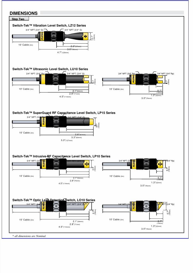
DIMENSIONS
Step Two
Switch-Tek™ Vibration Level Switch, LZ12 Series
3/4" NPT (3/4" G) 3/4" NPT (3/4" G)
0 . 7
"
( 1 8 m m
)
10' Cable (3m)2.3"(57mm)
3.0"(76mm)
4.7"(120mm)
Switch-Tek™ Ultrasonic Level Switch, LU10 Series
0 . 7
"
( 1 9 m m )
2.8"(71mm)
2.1"(54mm)
4.5"(114mm)
3/4" NPT (3/4" G)3/4" NPT (3/4" Rp)
10' Cable (3m)
1.3"(32mm)
10' Cable (3m)
0 . 7
"
( 1 9 m m
)
0.7"(19mm)
3.0"(76mm)
3/4" NPT (3/4" Rp)3/4" NPT (3/4" Rp)
Switch-Tek™ SuperGuard RF Capacitance Level Switch, LP15 Series
3/4" NPT (3/4" Rp) 3/4" NPT (3/4" G)
0 . 7
"
( 1 9 m m )
10' Cable (3m)2.6"(67mm)
3.3"(83mm)
5.0"(127mm)
Switch-Tek™ Intrusive RF Capacitance Level Switch, LP10 Series
3/4" NPT (3/4" Rp) 3/4" NPT (3/4" G)
0 . 7
"
( 1 9 m m
)
3/4" NPT (3/4" Rp)3/4" NPT (3/4" Rp)
0 . 7
"
( 1 9 m m )
10' Cable (3m) 10' Cable (3m)0.7"2.1"(54mm)
(19mm)2.8"(70mm)
1.3"(32mm)4.5"(114mm)
3.0"(76mm)
Switch-Tek™ Optic Leak Detection Switch, LO10 Series
3/4" NPT (3/4" Rp) 3/4" NPT (3/4" G)
0 . 7
"
( 1 9 m m )
3/4" NPT (3/4" Rp) 3/4" NPT (3/4" Rp)
0 . 7
"
( 1 9 m m
)
10' Cable (3m)10' Cable (3m)0.7"2.1"(54mm)
(19mm)2.8"(71mm)
1.3"(32mm)4.5"(114mm)
3.0"(76mm)
* all dimensions are Nominal

7/28/2019 FlowLine Level Switch Sensors Switch-Tek LU10 LP10 LP15 LO10 LZ12 Manual
http://slidepdf.com/reader/full/flowline-level-switch-sensors-switch-tek-lu10-lp10-lp15-lo10-lz12-manual 4/8
SAFETY PRECAUTIONS INTRODUCTION
Step Three
About this Manual:PLEASE READ THE ENTIRE MANUAL PRIOR TO
INSTALLING OR USING THIS PRODUCT. This manual
includes information on all models of Flowline Switch-Tek™
Powered Level Switches: LZ12, LU10, LP15, LP10 and LO10
series. Please refer to the part number located on the switch label
to verify the exact model which you have purchased.
User’s Responsibility for Safety:Flowline manufactures a wide range of liquid level sensors and
technologies. While each of these sensors is designed to operate in
a wide variety of applications, it is the user’s responsibility to select
a sensor model that is appropriate for the application, install it
properly, perform tests of the installed system, and maintain all
components. The failure to do so could result in property damage
or serious injury.
Proper Installation and Handling:Because this is an electrically operated device, only properly-
trained staff should install and/or repair this product. Use a proper
sealant with all installations. Note: Always install the 3/4” Viton
gasket with all versions of Switch-Tek™ with metric threads. TheG threaded version will not seal unless the gasket is properly
installed. Never overtighten the sensor within the fitting, beyond a
maximum of 80 inch-pounds torque. Always check for leaks prior
to system start-up.
Material Compatibility:The LU10, LP10 and LO10 series sensors are available in two different
wetted materials. Models L_10-1__5 are made of Polypropylene(PP).
Models L_10-2__5 are made of Perfluoroalkoxy(PFA). The LZ12
series is made of made of Ryton® (40% glass filled) and the LP15
series is made of PP. Make sure that the model you have selected is
compatible with the application liquid. To determine the chemical
compatibility between the sensor and its application liquids, refer to an
industry reference such as the Compass Corrosion Guide (available
from Compass Publications, phone 858-589-9636).
Wiring and Electrical:The supply voltage used to power the sensor should never exceed
a maximum of 36 volts DC (30 VDC for LZ12 series). Electrical
wiring of the sensor should be performed in accordance with all
applicable national, state, and local codes.
Flammable, Explosive and Hazardous Applications:Only the LU10-___5 series switch is rated for use in hazardous
locations. Refer to the Certificate of Compliance for all applicable
intrinsically safe ratings and entity parameters. Refer to the
National Electric Code (NEC) for all applicable installation
requirements in hazardous locations. DO NOT USE THE LZ12,
LP15, LP10 OR LO10 SERIES GENERAL PURPOSE SWITCHIN HAZARDOUS LOCATIONS.
WARNING
The rating for the relay is 60 VA.
Flowline’s Switch-Tek™ level switches are not recommended
for use with electrically charged application liquids. For most
reliable operation, the liquid being measured may need to be
electrically grounded.
Always install the 3/4” Viton gasket with all versions of the
powered sensors with metric threads. The G threaded version
will not seal unless the gasket is installed properly.
Step Four
Vibration Switch:The Tuning Fork vibration switch operates at a nominal frequency of
400 Hz. As the switch becomes immersed in a liquid or slurry, a cor
responding frequency shift occurs. When the measured frequency
shift reaches the set point value, the switch changes state indicating
the presence of a liquid or slurry medium. For optimum performance
and proactive maintenance, the sensor automatically adjusts for coat
ing, and if necessary, outputs a preventative maintenance alarm.
Do not squeeze the forks together. Doing so could damage
or break the sensor and void the warranty.
When powering up the LZ12, the start-up procedure requires the
switch to cycle through a wet condition for 1/2 second in order to
determine an initial resonance.
Ultrasonic Switch:The Ultrasonic level switch generates a 1.5 MHz ultrasonic wave
from a miniature piezoelectric transducer located on one side of the
gap in its sensing tip. Another piezo transducer located on the other
side of the gap acts as a microphone, picking up the sound. When
liquid enters the gap in the sensing tip, the audio level changes.
The sensor should be installed so that the liquid will drip out
of the gap when the sensor becomes dry.
Optic Switch:The Optic Leak Detector use principles of optical refraction to detect
the presence or absence of fluid. A pulsed infrared light beam is
internally generated by a light emitting diode and aimed at the slanted
optical tip of the sensor. If the tip is dry, the light beam bounces at a
90 degree angle to a receiving photo transistor, indicating a dry condi
tion. If the tip is immersed in liquid, the light beam will refract out
into the liquid instead of being reflected to the photo transistor, indi
cating a wet condition.
The Optic Leak Detector can not detect the presence or
absence of specular application liquids that reflect light
(such as milk), or viscous liquids (such as paint) that form a
coating on the sensor tip.
SuperGuard Capacitance Switch:The SuperGuard level switch generates a pulse-wave radio frequency
signal from the capacitance electrode located in the sensing tip of
each sensor. When liquid comes into contact with the sensing tip, the
capacitance as measured by the sensor changes based on the dielectric
constant of the liquid. The guard circuit rejects the negative effects of
coating buildup on the probe by eliminating the coating signal path
between the active and reference electrodes.
Intrusive RF Capacitance Switch:
The Intrusive RF Capacitance level switch generates a 300 kHz pulse-wave radio frequency signal from the capacitance electrode located in
the sensing tip of each sensor. When liquid comes into contact with
the sensing tip, the capacitance as measured by the sensor changes
based on the dielectric constant of the liquid.
The sensor’s operation may vary based on the dielectric
properties of various application liquids. The LP15 & LP10
series sensor is factory-calibrated to be used with liquids
with a dielectric value between 20 and 80. Liquids with a
dielectr ic cons tant le ss than 20 wi ll not be detected by
an LP15 & LP10 series sensor, as factory ca librated.

7/28/2019 FlowLine Level Switch Sensors Switch-Tek LU10 LP10 LP15 LO10 LZ12 Manual
http://slidepdf.com/reader/full/flowline-level-switch-sensors-switch-tek-lu10-lp10-lp15-lo10-lz12-manual 5/8
-
INSTALLATION ELECTRICALStep Five Step Six
Through Wall Installation:Flowline’s Switch-Tek™ level switches may be installed through the
top, side or bottom of a tank wall. The sensor has male 3/4" NPT
threads on either side of a 15/16" wrench flat. This enables the user to
select the sensor’s mounting orientation, installed outside of the tank
in, or inside of the tank out.
Supply Voltage:
The supply voltage to the Switch-Tek™ level switch should never
exceed a maximum of 36 VDC. Flowline controllers have a built-in
13.5 VDC power supply which provides power to all of Flowline’s
electrically powered sensors. Alternative controllers and power sup
plies, with a minimum output of 12 VDC up to a maximum output of
36 VDC, may also be used with the Switch-Tek™ level switch.
Required Cable Length:
Determine the length of cable required between the Switch-Tek™
level switch and its point of termination. Allow enough slack to
ensure the easy installation, removal and/or maintenance of the sen
sor. The cable length may be extended up to a maximum of 1000 feet
using a well-insulated, 14 to 20 gauge shielded four conductor cable
Wire Stripping:
Using a 10 gauge wire stripper, carefully remove the outer layer of
insulation from the last 1-1/4" of the sensor's cable. Unwrap and
discard the exposed foil shield from around the signal wires, leaving
the drain wire attached if desired. With a 20 gauge wire stripper
remove the last 1/4" of the colored insulation from the signal wires.
Signal Outputs (Current sensing):The standard method used by Flowline controllers; this technology uses
only two wires (Red and Black). The sensor draws 5 mA when it is dry
and 19 mA when wet. NC/NO status must be set by the controller. The
White and Green wires are not used.
Smart Trak™ Installation:Flowline’s Smart Trak LM10 series mounting system is an in-tank
fitting which enables users to install up to four FLOWLINE sensors
of any technology, to any depth, along the entire length of track.
Smart Trak may be installed through the top wall of any tank using a
standard 2" NPT tank adapter. If no tank top installation is available,
Flowline's side mount bracket, LM50-1001, enables Smart Trak to be
installed directly to the side wall of a tank. Do not use PFA Teflon
sensors with Smart-Trak.
Switch Pak™ Installation:Flowline’s Switch Pak LM45 series mounting system is an in-tank
fitting which enables users to install one FLOWLINE sensor, of any
technology, to a specific depth. The Flowline sensor may be installed
onto the 3/4" NPT adapter at the end of the Switch Pak. Switch Pak
may be installed through the top wall of any tank using a standard 2"
NPT tank adapter. Flowline's side mount bracket, model LM50-1001,
may also be used if top wall installation is not available.
Signal Output (Relay switching):
Allows the sensor to switch a small load on or off directly, using aninternal 1A relay (60 VAC/60 VDC). Only model LU10-___5 uses the
relay and features 4 wires (red, black, white and green) and a shield
wire. The NO/NC status is set by the polarity of the voltage feeding
the red and black wires. The green wire is the common for the relay
and the white wire is the NO or NC, depending on the polarity of red
and black.
Switch-TekHigh Level Switch
Switch Pak
LC06Junction
Box
Switch-TekLow Level Switch
1/2Coupling
Smart Trak
Red
Black
ShieldGround
24 VDC
Power Supply
+
Multimeter
(Continuity)
-
+
White
Green
Red24 VDC
Power Supply
+
-
Multimeter
(mA)
-
+Black
Always install the 3/4” Viton gasket with the metric (long
sensor length) versions of the L___-__2_. The G threaded
version of the Switch-Tek™ will not seal unless the gasket is
installed properly.
Normally Open Wiring:
Normally Closed Wiring:
Black
Red
ShieldGround
24 VDC
Power Supply
+
-
Multimeter
(Continuity)
-
+
White
Green

7/28/2019 FlowLine Level Switch Sensors Switch-Tek LU10 LP10 LP15 LO10 LZ12 Manual
http://slidepdf.com/reader/full/flowline-level-switch-sensors-switch-tek-lu10-lp10-lp15-lo10-lz12-manual 6/8
SENSOR POWER[RED & BLK Wires]36 VDC Max.5 ±1 mA Dry19 ±1 mA Wet
RELAY RATING[GRN & WHT Wires]60 VA Max.
SENSOR POWER[RED & BLK Wires]36 VDC Max.19 ±1 mA Dry
5 ±1 mA Wet
RELAY RATING[GRN & WHT Wires]60 VA Max.
SENSOR POWER[RED & BLK Wires]36 VDC Max.5 ±1 mA Dry19 ±1 mA Wet
RELAY RATING[GRN & WHT Wires]60 VA Max.
SENSOR POWER[RED & BLK Wires]36 VDC Max.19 ±1 mA Dry
RELAY RATING[GRN & WHT Wires]60 VA Max.
SENSOR POWER
[RED & BLK Wires]36 VDC Max.5 ±1 mA Dry19 ±1 mA Wet
RELAY RATING
[GRN & WHT Wires]60 VA Max.
MAINT. ALARM
[YEL Wire]
NPN Transistor
10 mA Max.
SENSOR POWER
[RED & BLK Wires]36 VDC Max.5 ±1 mA Dry19 ±1 mA Wet
RELAY RATING
[GRN & WHT W ires]60 VA Max.
MAINT. ALARM
[YEL Wire]
NPN Transistor10 mA Max.
- -I I
WIRING WIRINGStep Seven Step Eight
Wiring to a Flowline Controller:LC10 Series Controller
(4 or 20 mA signal output)
LC40 Series Controller
(4 or 20 mA signal output)
I N V E R T + / -
DELAY
AC
AC
GND
NC
C
NO
R
P
I n p u t 1
(-)
115 VAC220 VAC
(+)
G r e e n -
N o
t U s e
d
B l a c
k
S h i e l d -
N o
t U s e
d
W h i t e -
N o t U s e
d
R e
d
STANDARD
CONTROLLER
R E L A Y 1 RE L A Y 2
P O W E R
INPUT 1 INPUT 2A INPUT 2B
+ +
NVERT DELAY NVERT DELAY
LATCH
ONOFF
Shld
Not Used - White *
Red
Black
Not Used - Green*
[Dry Condition]
Sensor(NO)
RED
GRN
SHLD
WHT
BLK
LOAD
LOAD
OR
[+]
[-]
[Dry Condition]
Sensor(NC)
BLK
GRN
SHLD
WHT
RED
LOAD
LOAD
OR
[+]
[-]
[AC Power
[Dry Condition]
Sensor(NO)
RED
GRN
SHLD
WHT
BLK
LOAD
[+]
[-]
[AC Power
[Dry Condition]
Sensor(NC)
BLK
GRN
SHLD
WHT
RED
LOAD
[+]
[-]
Wiring the Relay Output:The Switch-Tek™ relay output can be wired as a dry contact to a
VDC or VAC power source. Switch-Tek™ does require 12 - 36 VDC
power to operate the sensor and switch the relay. All illustrations
below identify a Dry switch state as the normal position of the relay.
Switching a Normally Open DC Load:
The Red wire connects to Positive (+) of the power supply and theBlack wire connects to Negative (-). The LOAD can be attached to
either the Green or White wires. Complete the circuit by either con
necting the Green to (+) VDC power or White to (-) VDC power (see
illustration below).
Switching a Normally Closed DC Load:
The Black wire connects to Positive (+) of the power supply and the
Red wire connects to Negative (-). The LOAD can be attached to
either the Green or White wires. Complete the circuit by either con
necting the Green to (+) VDC power or White to (-) VDC power (see
illustration below).
Switching a Normally Open AC Load:The Red wire connects to Positive (+) of the DC power supply and the
Black wire connects to Negative (-). The LOAD can be attached to
the Green wire and the Hot of the VAC power. Connect the White to
the Neutral of the VAC power (see illustration below).
Switching a Normally Closed AC Load:The Black wire connects to Positive (+) of the DC power supply and
the Red wire connects to Negative (-). The LOAD can be attached to
the Green wire and the Hot of the VAC power. Connect the White to
the Neutral of the VAC power (see illustration below).
[Dry Condition]
Sensor(NO)
RED
GRN
SHLD
WHT
YEL
BLK
[+]
[-]
2.2K
[Dry Condition]
Sensor(NO)
RED
GRN
SHLD
WHT
YEL
BLK
PLC
[+]
[-]
10K
24 VDC
Maintenance Alarm (LZ12 Vibration only):For optimum performance and proactive maintenance, the sensor
automatically adjusts for coating, and if necessary, outputs a preven
tative maintenance alarm. The Yellow wire is a NPN transistor
designed to switch when a build-up of material prevents the vibration
switch from operating at its operational frequency. Use the Yellow
wire to identify when the Vibration switch requires cleaning.
To wire the maintenance output wire to an LED, follow the wiring dia
gram below. The Yellow wire is connected to the LED and a 2.2kΩ
resister in series and referenced back to the (+) of the power supply.
To wire the maintenance output wire to an PLC, follow the wiring diagram below. The Yellow wire is connected to the PLC input with a 10
kΩ resister parallel to the PLC input and the (+) of the power supply.
7/28/2019 FlowLine Level Switch Sensors Switch-Tek LU10 LP10 LP15 LO10 LZ12 Manual
http://slidepdf.com/reader/full/flowline-level-switch-sensors-switch-tek-lu10-lp10-lp15-lo10-lz12-manual 7/8
Non-Hazardous Area Hazardous Area
- -I
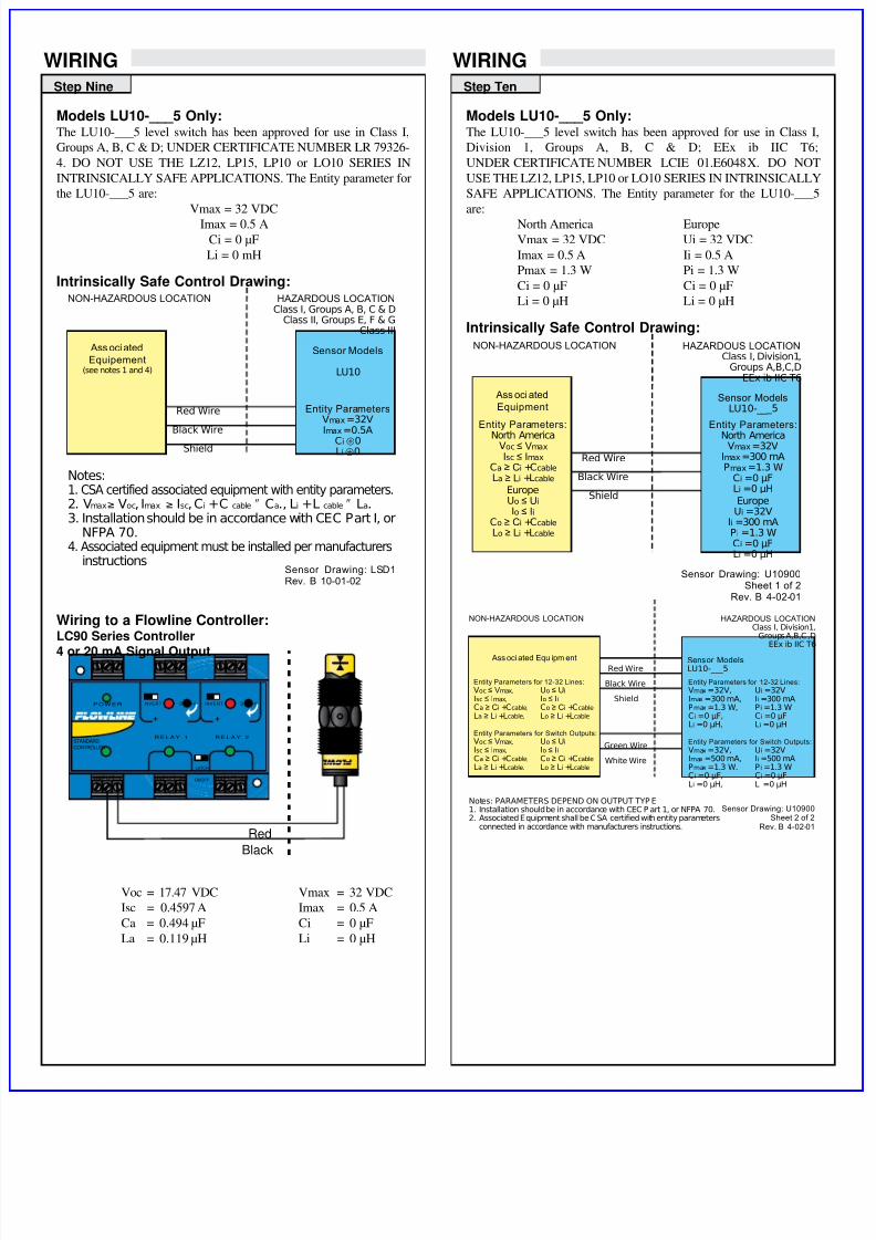
WIRING WIRINGStep TenStep Nine
Models LU10-___5 Only:The LU10-___5 level switch has been approved for use in Class I,
Groups A, B, C & D; UNDER CERTIFICATE NUMBER LR 79326
4. DO NOT USE THE LZ12, LP15, LP10 or LO10 SERIES IN
INTRINSICALLY SAFE APPLICATIONS. The Entity parameter for
the LU10-___5 are:
Vmax = 32 VDC
Imax = 0.5 A
Ci = 0 µF
Li = 0 mH
Intrinsically Safe Control Drawing:
Wiring to a Flowline Controller:LC90 Series Controller
4 or 20 mA Signal Output
Red Wire
Black WireShield
HAZARDOUS LOCATIONClass I, Groups A, B, C & D
Class II, Groups E, F & GClass III
NON-HAZARDOUS LOCATION
Sensor Drawing: LSD1Rev. B 10-01-02
Sensor Models
LU10
Entity ParametersVmax =32V
Imax =0.5ACi ⊕0Li ⊕0
Ass oci ated
Equipement(see notes 1 and 4)
Notes:1. CSA certified associated equipment with entity parameters.2. Vmax≥ Voc, Imax ≥ Isc, Ci +C cable ʺ Ca., Li +L cable ʺ La.3. Installation should be in accordance with CEC Part I, or
NFPA 70.4. Associated equipment must be installed per manufacturers
instructions
STANDARDCONTROLLER
R E L A Y 1 R E L A Y 2
P O W E R
INPUT 1 INPUT 2A INPUT 2B
+ +
NVERT DELAY INVERT DELAY
LATCH
ONOFF
Black
Red
Voc = 17.47 VDC
Isc = 0.4597 A
Ca = 0.494 µF
La = 0.119 µH
Vmax = 32 VDC
Imax = 0.5 A
Ci = 0 µF
Li = 0 µH
Models LU10-___5 Only:The LU10-___5 level switch has been approved for use in Class I
Division 1, Groups A, B, C & D; EEx ib IIC T6;
UNDER CERTIFICATE NUMBER LCIE 01.E6048X. DO NOT
USE THE LZ12, LP15, LP10 or LO10 SERIES IN INTRINSICALLY
SAFE APPLICATIONS. The Entity parameter for the LU10-___5
are:
North America Europe
Vmax = 32 VDC Ui = 32 VDC
Imax = 0.5 A Ii = 0.5 A
Pmax = 1.3 W Pi = 1.3 W
Ci = 0 µF Ci = 0 µF
Li = 0 µH Li = 0 µH
Intrinsically Safe Control Drawing:NON-HAZARDOUS LOCATION HAZARDOUS LOCATION
Class I, Division1,Groups A,B,C,D
EEx ib IIC T6
Ass oci ated Sensor ModelsEquipment LU10-__ _5
Entity Parameters: Entity Parameters:
North America North AmericaVoc ≤ Vmax Vmax =32VIsc ≤ Imax Red Wire Imax =300 mA
Ca ≥ Ci +Ccable Pmax =1.3 WLa ≥ Li +Lcable Black Wire Ci =0 µF
EuropeUo ≤ Ui
ShieldLi =0 µH
EuropeIo ≤ Ii Ui =32V
Co ≥ Ci +Ccable Ii =300 mALo ≥ Li +Lcable Pi =1.3 W
Ci =0 µFLi =0 µH
Sensor Drawing: U10900Sheet 1 of 2
Rev. B 4-02-01
Red Wire
Black Wire
Shield
NON-HAZARDOUS LOCATION
Ass oci ated Equ ipm ent
Entity Parameters for 12-32 Lines:
Voc ≤ Vmax, Uo ≤ Ui
Isc ≤ Imax, Io ≤ Ii
Ca ≥ Ci +Ccable, Co ≥ Ci +Ccable
La ≥ Li +Lcable, Lo ≥ Li +Lcable
Entity Parameters for Switch Outputs:
Voc ≤ Vmax, Uo ≤ Ui
Isc ≤ Imax, Io ≤ Ii
Ca ≥ Ci +Ccable, Co ≥ Ci +Ccable
La ≥ Li +Lcable, Lo ≥ Li +Lcable
Green Wire
White Wire
HAZARDOUS LOCATIONClass I, Division1,
Groups A,B,C,DEEx ib IIC T6
Sensor Models
LU10-___5
Entity Parameters for 12-32 Lines:
Vmax =32V, Ui =32VImax =300 mA, Ii =300 mAPmax =1.3 W, P i =1.3 WCi =0 µF, Ci =0 µFLi =0 µH, Li =0 µH
Entity Parameters for Switch Outputs:
Vmax =32V, Ui =32VImax =500 mA, Ii =500 mAPmax =1.3 W, P i =1.3 WCi =0 µF, Ci =0 µFLi =0 µH, Li =0 µH
Notes: PARAMETERS DEPEND ON OUTPUT TYP E1. Installation should be in accordance with CEC P art 1, or NFPA 70. Sensor Drawing: U109002. Associated Equipment shall be CSA certified with entity parameters Sheet 2 of 2 connected in accordance with manufacturers instructions. Rev. B 4-02-01

7/28/2019 FlowLine Level Switch Sensors Switch-Tek LU10 LP10 LP15 LO10 LZ12 Manual
http://slidepdf.com/reader/full/flowline-level-switch-sensors-switch-tek-lu10-lp10-lp15-lo10-lz12-manual 8/8
SENSOR POWER
[RED & BLK Wires]
36 VDC Max.5 ±1 mA Dry19 ±1 mA Wet
RELAY RATING
[GRN & WHT Wires]
60 VA Max.
SENSOR POWER
[RED & BLK Wires]36 VDC Max.5 ±1 mA Dry19 ±1 mA Wet
RELAY RATING
[GRN & WHT Wires]60 VA Max.
SENSOR POWER[RED & BLK Wires]36 VDC Max.5 ±1 mA Dry19 ±1 mA Wet
RELAY RATING[GRN & WHT Wires]60 VA Max.
SENSOR POWER RELAY RATING
SENSOR POWER
[RED & BLK Wires]36 VDC Max.5 ±1 mA Dry19 ±1 mA Wet
RELAY RATING
[GRN & WHT Wires]60 VA Max.
MAINT. ALARM
[YEL Wire]
NPN Transistor
10 mA Max.
SENSOR POWER RELAY RATING MAINT. ALARM
WIRING MAINTENANCEStep Twelve
General:The Switch-Tek™ level switch requires no periodic maintenance
except cleaning as required. It is the responsibility of the user to
determine the appropriate maintenance schedule, based on the spe
cific characteristics of the application liquids.
Cleaning Procedure:
1. Power: Make Sure that all power to the sensor, controller and/orpower supply is completely disconnected.
2. Sensor Removal: In all through-wall installations, make sure
that the tank is drained well below the sensor prior to removal.
Carefully, remove the sensor from the installation.
3. Cleaning the Sensor: Use a soft bristle brush and mild deter
gent, carefully wash the Switch-Tek™ level switch. Do not use
harsh abrasives such as steel wool or sandpaper, which might
damage the surface sensor. Do not use incompatible solvents
which may damage the sensor's PP, PFA, PVDF or Ryton plastic
body.
4. Sensor Installation: Follow the appropriate steps of installa
tion as outlined in the installation section of this manual.
Testing the installation:1. Power: Turn on power to the controller and/or power supply.
2. Immersing the switch: Immerse the sensing tip in its applica
tion liquid, by filling the tank up to the switches point of actua
tion. An alternate method of immersing the switch during pre
liminary testing is to hold a cup filled with application liquid up
to the switch's tip.
3. Test: With the switch being fluctuated between wet and dry
states, the switch indicator light in the controller should turn on
and off. If the controller doesn't have an input indicator, use a
voltmeter or ammeter to ensure that the switch produces the cor
rect signal.
4. Point of actuation: Observe the point at which the rising or
falling fluid level causes the switch to change state, and adjust the
installation of the switch if necessary.
Maintenance Output to LED (LZ12 Only):
To wire the maintenance output wire to an LED, follow the wiring dia
gram below. The Yellow wire is connected to the LED and a 2.2kΩ
resister in series and referenced back to the (+) of the power supply.
Step Eleven
Wiring as a P-Channel or N-Channel output:The Switch-Tek™ can be substituted for either a P-Channel (PNP,
sourcing) output or a N-Channel (NPN, sinking) output.
Normally Open DC Load as a P-Channel Output:
To wire as a NO P-Channel output, follow the directions below. The
Red wire connects to Positive (+) of the power supply and the Black
wire connects to Negative (-). The Green wire is jumpered to the Redwire while the White wire is connected to the LOAD. Jumper the
LOAD back to the Negative (-) to complete the circuit.
[Dry Condition]
Sensor(NO)
RED
GRN
SHLD
WHT
BLK
LOAD
[+]
[-]
[Dry Condition]
Sensor(NO)
BLK
GRN
SHLD
WHT
RED
LOAD
[+]
[-]
[Dry Condition]
Sensor(NO)
RED
GRN
SHLD
WHT
BLK
LOAD
[+]
[-]
[Dry Condition]
Sensor(NO)
BLK
GRN
SHLD
WHT
RED
LOAD
[+]
[-]
Normally Closed DC Load as a N-Channel Output:
To wire as a NC N-Channel output, follow the directions below. The
Black wire connects to Positive (+) of the power supply and the Red
wire connects to Negative (-). The White wire is jumpered to the Red
wire while the White wire is connected to the LOAD. Jumper the
LOAD back to the Positive (+) to complete the circuit.
Normally Open DC Load as a N-Channel Output:
To wire as a NO N-Channel output, follow the directions below. TheRed wire connects to Positive (+) of the power supply and the Black
wire connects to Negative (-). The White wire is jumpered to the
Black wire while the Green wire is connected to the LOAD. Jumper
the LOAD back to the Positive (+) to complete the circuit.
Normally Closed DC Load as a P-Channel Output:
To wire as a NC P-Channel output, follow the directions below. The
Black wire connects to Positive (+) of the power supply and the Redwire connects to Negative (-). The Green wire is jumpered to the
Black wire while the White wire is connected to the LOAD. Jumper
the LOAD back to the Negative (-) to complete the circuit.
[Dry Condition]
Sensor(NO)
RED
GRN
SHLD
WHT
YEL
BLK
[+]
[-]
2.2K
[Dry Condition]
Sensor(NO)
RED
GRN
SHLD
WHT
YEL
BLK
PLC
[+]
[-]
10K
24 VDC
Maintenance Output to PLC (LZ12 Only):
To wire the maintenance output wire to an PLC, follow the wiring dia
gram below. The Yellow wire is connected to the PLC input with a 10
kΩ resister parallel to the PLC input and the (+) of the power supply.