
Swift Jamming Attack on Frequency Offset …krunz/Papers/Journals/TMC2016_hanif.pdfSwift Jamming...
14
1536-1233 (c) 2015 IEEE. Personal use is permitted, but republication/redistribution requires IEEE permission. See http://www.ieee.org/publications_standards/publications/rights/index.html for more information. This article has been accepted for publication in a future issue of this journal, but has not been fully edited. Content may change prior to final publication. Citation information: DOI 10.1109/TMC.2015.2456916, IEEE Transactions on Mobile Computing 1 Swift Jamming Attack on Frequency Offset Estimation: The Achilles’ Heel of OFDM Systems Hanif Rahbari, Marwan Krunz, Fellow, IEEE, and Loukas Lazos Abstract—Frequency offset (FO) refers to the difference in the operating frequencies of two radio oscillators. Failure to compensate for the FO may lead to decoding errors, particularly in OFDM systems. To correct the FO, wireless standards append a publicly known preamble to every frame before transmission. In this paper, we demonstrate how an adversary can exploit the known preamble structure of OFDM-based wireless systems, particularly IEEE802.11a/g/n/ac, to launch a very stealth (low energy/duty cycle) reactive jamming attack against the FO estimation mechanism. In this attack, the adversary quickly detects a transmitted OFDM frame and subsequently jams a tiny part of the preamble that is used for FO estimation at the legitimate receiver. By optimizing the energy and structure of the jamming signal and accounting for frame detection timing errors and unknown channel parameters, we empirically show that the adversary can induce a bit error rate close to 0.5, making the transmission practically irrecoverable. Such vulnerability to FO jamming exists even when the frame is shielded by efficient channel coding. We evaluate the FO estimation attack through simulations and USRP experimentation. We also propose three approaches to mitigate such an attack. Index Terms—PHY-layer security, frequency offset, OFDM, reactive jamming, IEEE802.11, USRP implementation. ✦ 1 I NTRODUCTION C OMMUNICATION between two wireless devices in- volves several concerted functions at the physical (PHY) layer, including time synchronization, carrier fre- quency offset (FO) correction, channel estimation, channel coding, modulation, interleaving, and others [2]. PHY-layer functions are designed to combat oscillator imperfections and wireless channel impairments, and to decode wireless signals that are corrupted by a limited amount of interfer- ence. However, wireless transmissions still remain vulnera- ble to intentional interference attacks, commonly referred to as jamming. One measure of the effectiveness of a jamming attack is its duty cycle, i.e., the fraction of the frame that needs to be jammed so that the frame is discarded at the receiver (Rx) [3], [4]. This metric is directly related to the jammer’s distance to the Rx, energy budget, and the ability to disrupt concurrent transmissions. A jammer that remains active for a longer period can corrupt more bits and defeat stronger error correction codes (ECCs), at the expense of higher en- ergy consumption and fewer targeted communications. This more potent jammer is also easier to detect [5], localize, and physically remove using jammer localization methods [4]. In this paper, we investigate an extremely low duty cycle jamming model that is facilitated by public knowledge of the frame structure and PHY-layer functions. Our goal is to demonstrate how an adversary can inflict the highest possible number of decoding errors at the Rx, without jamming the corresponding header or payload symbols. • H. Rahbari, M. Krunz, and L. Lazos are with the Department of Electrical and Computer Engineering, University of Arizona, Tucson, AZ 85721. E-mail: {rahbari,krunz,llazos}@ email.arizona.edu • An abridged version of this paper appeared in the Proceedings of the IEEE INFOCOM Conference, April 2014 [1]. PHY-layer standards usually employ publicly known se- quences, known as preambles, at the beginning of a frame to acquire important communication parameters, such as the transmission timing, channel, and FO [2]. These parameters are used to align received symbols. An adversary may exploit the publicity of the preamble to construct a reactive jamming attack and target the estimation of these critical parameters. In particular, we demonstrate the feasibility of an energy-efficient and low duty cycle attack against the FO estimation process of IEEE 802.11 OFDM-based devices (including 802.11a, .11g, .11n, .11ac, and 11ah), all of which exploit the same preamble structure. Our results can be ex- tended to other OFDM-based systems, including 802.16e/m (WiMAX), LTE, and 5G. The jamming of OFDM systems has recently been the subject of extensive research (e.g., [6]–[12]). These works often consider vulnerabilities in time synchronization or susceptibility to inter-carrier interference (ICI). For exam- ple, the authors in [8] proposed several jamming attacks against OFDM time synchronization, including barrage at- tacks, false preamble timing, and preamble warping. In the barrage attack, white noise is transmitted to decrease the SNR during synchronization. In false preamble timing, the jammer forges a preamble to fool the Rx about the true start time of the frame. A similar technique was used in [9] against an 802.11b Rx to hamper the network throughput. Preamble warping tries to destroy the time-domain correla- tion (used for time acquisition) within the preamble. 1.1 Frequency Offset Estimation Attacks In OFDM systems, frequency synchronization errors are more devastating than timing errors [13]. When two radios are tuned to the same target frequency, their oscillators can-
Transcript of Swift Jamming Attack on Frequency Offset …krunz/Papers/Journals/TMC2016_hanif.pdfSwift Jamming...
1536−1233 (c) 2015 IEEE. Personal use is permitted, but republication/redistribution requires IEEE permission. Seehttp://www.ieee.org/publications_standards/publications/rights/index.html for more information.
This article has been accepted for publication in a future issue of this journal, but has not been fully edited. Content may change prior to final publication. Citation information: DOI10.1109/TMC.2015.2456916, IEEE Transactions on Mobile Computing
1
Swift Jamming Attack on Frequency OffsetEstimation: The Achilles’ Heel of OFDM
Systems
Hanif Rahbari, Marwan Krunz, Fellow, IEEE, and Loukas Lazos
Abstract—Frequency offset (FO) refers to the difference in the operating frequencies of two radio oscillators. Failure to compensate for
the FO may lead to decoding errors, particularly in OFDM systems. To correct the FO, wireless standards append a publicly known
preamble to every frame before transmission. In this paper, we demonstrate how an adversary can exploit the known preamble
structure of OFDM-based wireless systems, particularly IEEE802.11a/g/n/ac, to launch a very stealth (low energy/duty cycle) reactive
jamming attack against the FO estimation mechanism. In this attack, the adversary quickly detects a transmitted OFDM frame and
subsequently jams a tiny part of the preamble that is used for FO estimation at the legitimate receiver. By optimizing the energy and
structure of the jamming signal and accounting for frame detection timing errors and unknown channel parameters, we empirically
show that the adversary can induce a bit error rate close to 0.5, making the transmission practically irrecoverable. Such vulnerability to
FO jamming exists even when the frame is shielded by efficient channel coding. We evaluate the FO estimation attack through
simulations and USRP experimentation. We also propose three approaches to mitigate such an attack.
Index Terms—PHY-layer security, frequency offset, OFDM, reactive jamming, IEEE802.11, USRP implementation.
✦
1 INTRODUCTION
COMMUNICATION between two wireless devices in-volves several concerted functions at the physical
(PHY) layer, including time synchronization, carrier fre-quency offset (FO) correction, channel estimation, channelcoding, modulation, interleaving, and others [2]. PHY-layerfunctions are designed to combat oscillator imperfectionsand wireless channel impairments, and to decode wirelesssignals that are corrupted by a limited amount of interfer-ence. However, wireless transmissions still remain vulnera-ble to intentional interference attacks, commonly referred toas jamming.
One measure of the effectiveness of a jamming attack isits duty cycle, i.e., the fraction of the frame that needs tobe jammed so that the frame is discarded at the receiver(Rx) [3], [4]. This metric is directly related to the jammer’sdistance to the Rx, energy budget, and the ability to disruptconcurrent transmissions. A jammer that remains active fora longer period can corrupt more bits and defeat strongererror correction codes (ECCs), at the expense of higher en-ergy consumption and fewer targeted communications. Thismore potent jammer is also easier to detect [5], localize, andphysically remove using jammer localization methods [4].
In this paper, we investigate an extremely low duty cyclejamming model that is facilitated by public knowledge ofthe frame structure and PHY-layer functions. Our goal isto demonstrate how an adversary can inflict the highestpossible number of decoding errors at the Rx, withoutjamming the corresponding header or payload symbols.
• H. Rahbari, M. Krunz, and L. Lazos are with the Department of Electricaland Computer Engineering, University of Arizona, Tucson, AZ 85721.E-mail: {rahbari,krunz,llazos}@ email.arizona.edu
• An abridged version of this paper appeared in the Proceedings of the IEEEINFOCOM Conference, April 2014 [1].
PHY-layer standards usually employ publicly known se-quences, known as preambles, at the beginning of a frame toacquire important communication parameters, such as thetransmission timing, channel, and FO [2]. These parametersare used to align received symbols. An adversary mayexploit the publicity of the preamble to construct a reactivejamming attack and target the estimation of these criticalparameters. In particular, we demonstrate the feasibility ofan energy-efficient and low duty cycle attack against theFO estimation process of IEEE 802.11 OFDM-based devices(including 802.11a, .11g, .11n, .11ac, and 11ah), all of whichexploit the same preamble structure. Our results can be ex-tended to other OFDM-based systems, including 802.16e/m(WiMAX), LTE, and 5G.
The jamming of OFDM systems has recently been thesubject of extensive research (e.g., [6]–[12]). These worksoften consider vulnerabilities in time synchronization orsusceptibility to inter-carrier interference (ICI). For exam-ple, the authors in [8] proposed several jamming attacksagainst OFDM time synchronization, including barrage at-tacks, false preamble timing, and preamble warping. In thebarrage attack, white noise is transmitted to decrease theSNR during synchronization. In false preamble timing, thejammer forges a preamble to fool the Rx about the truestart time of the frame. A similar technique was used in [9]against an 802.11b Rx to hamper the network throughput.Preamble warping tries to destroy the time-domain correla-tion (used for time acquisition) within the preamble.
1.1 Frequency Offset Estimation Attacks
In OFDM systems, frequency synchronization errors aremore devastating than timing errors [13]. When two radiosare tuned to the same target frequency, their oscillators can-
1536−1233 (c) 2015 IEEE. Personal use is permitted, but republication/redistribution requires IEEE permission. Seehttp://www.ieee.org/publications_standards/publications/rights/index.html for more information.
This article has been accepted for publication in a future issue of this journal, but has not been fully edited. Content may change prior to final publication. Citation information: DOI10.1109/TMC.2015.2456916, IEEE Transactions on Mobile Computing
2
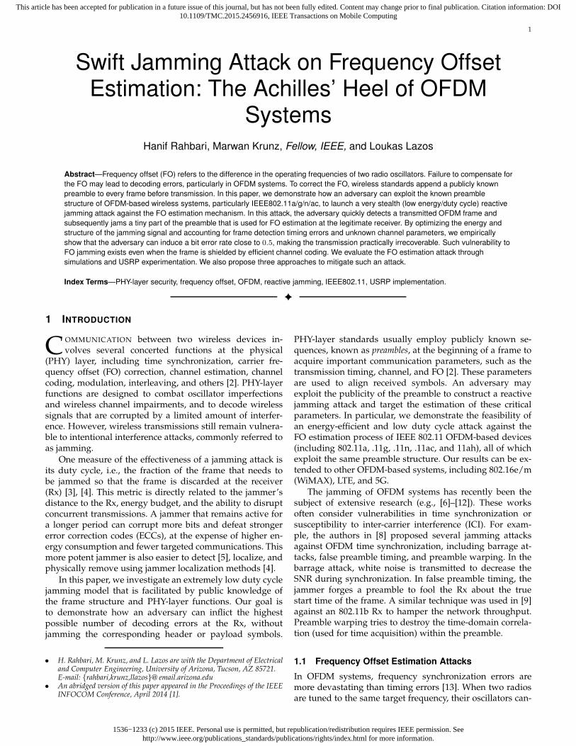
Fig. 1. Effect of uncompensated FO on a bitmap image over a noiselesschannel (FO = 0.32% of the subcarrier spacing).
not be exactly aligned to that frequency due to hardware im-perfections. FO is the inherent difference between the actualfrequencies of these two oscillators. In OFDM, FO is usuallynormalized to the inter-subcarrier frequency interval, calledsubcarrier spacing. Without frequency synchronization, theperformance of OFDM degrades severely because all sub-carriers will move away from their expected frequencies,resulting in subcarriers’ orthogonality violation, ICI [13],and channel estimation errors [1], [14].
To appreciate the significance of correct FO estimation,we conduct a simulation experiment in which a frame con-taining a bitmap image is transmitted between two nodes.Fig. 1 depicts the effect of a small FO estimation error (0.32%of subcarrier spacing) on the transmitted image (left) when48 subcarriers are used at a rate of 6 Mbps. The receivedimage (right) exhibits noticeable degradation in the formof image block misplacement. In practice, FO can be evenlarger than the subcarrier spacing [2].
A few jamming schemes have been proposed in theliterature (e.g., [7], [9], [10]) with the goal of inflictingICI. Phase warping and differential scrambling attacks [10]consider the preamble structure of Schmidl and Cox [15],which is different from the one used in 802.11 OFDM-basedstandards, and in essence try to alter preamble symbols in aheuristic fashion without providing any success guarantees.Gummadi et al. [9] showed the vulnerability of 802.11aclock (frequency) synchronization to a certain narrow-bandjamming pattern that interferes with the entire preamble.In [7] the jammer transmits multiple asynchronous subcar-riers to cause ICI in an OFDM symbol. These attacks mayfail if robust ECC, interleaving methods, or additional FOestimation mechanisms are employed at the Rx.
1.2 Contributions
We design an energy-efficient jamming attack that interfereswith a small portion of the preamble, i.e., one of the partsused for FO estimation, and causes one or two units shiftof the subcarrier indices (e.g., every subcarrier takes theposition of its next/previous subcarrier). To make this de-sign possible, the adversary (Eve) must first estimate theFO between the legitimate transmitter (Alice) and intendedreceiver (Bob), and then quickly detect the transmission ofa target frame. We provide an adaptive frame detectionmethod to facilitate fast detection at Eve. The superpositionof the jamming signal with the preamble are designed todelude Bob into estimating an FO that is sufficiently farfrom the true FO, so that Bob decodes wrong symbols, i.e.,the symbols of adjacent subcarriers. The idea is to come upwith a structure that is similar to the actual preamble soas to control the FO embedded in the jamming sequence.
The superposition of these two signals with different FOs atthe Rx achieves sufficient FO estimation error. We derivethe amount of FO estimation error needed to guaranteeerroneous OFDM demodulation and accordingly, developan optimal attack strategy. To ensure that the jamming signalis independent of the Alice-Bob channel parameters (whichare unknown to Eve), we propose a pairing scheme for thejamming sequence. The jamming attack should also accountfor timing errors in frame detection at Eve while keepingthe jamming signal channel-independent. For this purpose,a chaining scheme is designed on top of the pairing schemeto account for other possible frame start times.
Consequently, not only the channel estimation is auto-matically corrupted at Bob, but more importantly, all the fre-quency subcarriers are shifted forward or backward. Hence,Bob will have a shifted version of the bitstream transmittedin every OFDM symbol. Combined with a faulty channelestimation and thus demodulation errors, the bits becomeirrecoverable. We further optimize the power of this jam-ming attack and experimentally evaluate its performanceon a USRP testbed. In contrast to previous attacks on theframe preamble, ours in essence does not aim at necessarilycausing ICI. It is also different from the attacks in [7], [9],[10] in that it is channel-independent and energy-efficient, i.e.,only a small portion of the preamble is jammed irrespectiveof the jammer’s location. This short-lived attack lasts for lessthan 3 µs per frame (equivalent to, for example, about 0.5%of 802.11a’s maximum frame duration when the data rate isat its highest value). Note that this is even shorter than theduration of an OFDM symbol (4 µs). Our proposed attackalso disarms all the provisioned FO estimation methods byjust efficiently defeating one of them. Our work focuses onthe 802.11 OFDM-based wireless systems, and efficientlyexploits their FO vulnerability for the first time.
The paper is organized as follows. In Section 2, weprovide background on frame detection, FO estimation,and channel estimation in OFDM-based 802.11 standards.The system model, assumptions, and evaluation metrics aregiven in Section 3. The proposed attack and the optimaljamming strategy are presented in Section 4 and relatedissues are discussed in Section 5. Section 6 demonstrates theeffectiveness of the attack through simulations and experi-ments. Finally, we propose possible remedies and provide asummary of existing attacks in Sections 7 and 8, respectively.
2 FRAME DETECTION AND FO CORRECTION IN
OFDM SYSTEMS
In OFDM, a bitstream is split into several substreams, eachof which is digitally modulated and transmitted over one ofthe orthogonal frequency channels (subcarriers). For exam-ple, 802.11a/g defines 64 subcarriers with subcarrier spac-ing f∆ = 312.5 kHz within a bandwidth of 20 MHz. Only 48of these subcarriers are used for data. Four other subcarrierscarry pilot signals and the remaining 12 subcarriers are notused. So an 802.11a/g OFDM symbol is transmitted over 52subcarriers.
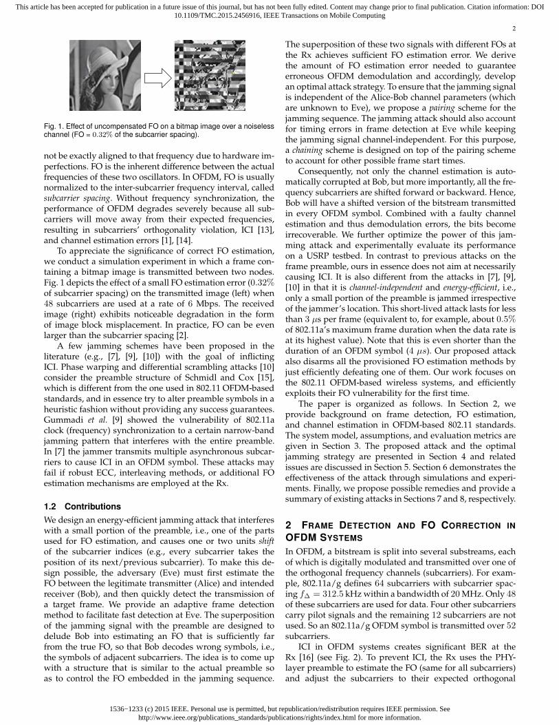
ICI in OFDM systems creates significant BER at theRx [16] (see Fig. 2). To prevent ICI, the Rx uses the PHY-layer preamble to estimate the FO (same for all subcarriers)and adjust the subcarriers to their expected orthogonal
1536−1233 (c) 2015 IEEE. Personal use is permitted, but republication/redistribution requires IEEE permission. Seehttp://www.ieee.org/publications_standards/publications/rights/index.html for more information.
This article has been accepted for publication in a future issue of this journal, but has not been fully edited. Content may change prior to final publication. Citation information: DOI10.1109/TMC.2015.2456916, IEEE Transactions on Mobile Computing
3
FO
ICI
f
ICI
f
ICI
Fig. 2. Inter-carrier interference (ICI) as a result of uncorrected FO in asystem with three subcarriers.
frequency bins. If the offset is less than half of the frequencydistance between the subcarriers, the Rx can safely identifythe frequency bin that each subcarrier belongs to.
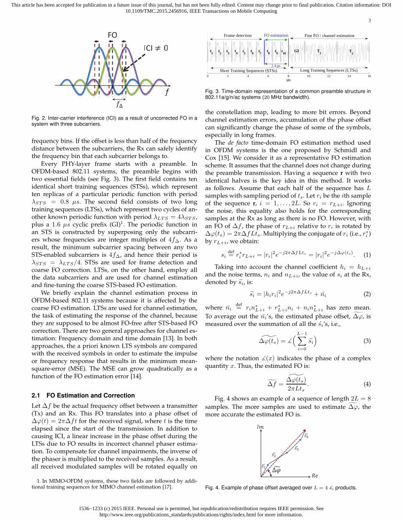
Every PHY-layer frame starts with a preamble. InOFDM-based 802.11 systems, the preamble begins withtwo essential fields (see Fig. 3). The first field contains tenidentical short training sequences (STSs), which representten replicas of a particular periodic function with periodλSTS = 0.8 µs. The second field consists of two longtraining sequences (LTSs), which represent two cycles of an-other known periodic function with period λLTS = 4λSTS ,plus a 1.6 µs cyclic prefix (GI)1. The periodic function inan STS is constructed by superposing only the subcarri-ers whose frequencies are integer multiples of 4f∆. As aresult, the minimum subcarrier spacing between any twoSTS-enabled subcarriers is 4f∆, and hence their period isλSTS = λLTS/4. STSs are used for frame detection andcoarse FO correction. LTSs, on the other hand, employ allthe data subcarriers and are used for channel estimationand fine-tuning the coarse STS-based FO estimation.
We briefly explain the channel estimation process inOFDM-based 802.11 systems because it is affected by thecoarse FO estimation. LTSs are used for channel estimation,the task of estimating the response of the channel, becausethey are supposed to be almost FO-free after STS-based FOcorrection. There are two general approaches for channel es-timation: Frequency domain and time domain [13]. In bothapproaches, the a priori known LTS symbols are comparedwith the received symbols in order to estimate the impulseor frequency response that results in the minimum mean-square-error (MSE). The MSE can grow quadratically as afunction of the FO estimation error [14].
2.1 FO Estimation and Correction
Let ∆f be the actual frequency offset between a transmitter(Tx) and an Rx. This FO translates into a phase offset of∆ϕ(t) = 2π∆ft for the received signal, where t is the timeelapsed since the start of the transmission. In addition tocausing ICI, a linear increase in the phase offset during theLTSs due to FO results in incorrect channel phaser estima-tion. To compensate for channel impairments, the inverse ofthe phaser is multiplied to the received samples. As a result,all received modulated samples will be rotated equally on
1. In MIMO-OFDM systems, these two fields are followed by addi-tional training sequences for MIMO channel estimation [17].
0 2 4 6 8 10 12 14 16µs
t10
t1
t2
t3
t4
t5
t6
t7
t8
t9
GI T1
T2
Frame detection FO estimation Fine FO / channel estimation
Long Training Sequences (LTSs)Short Training Sequences (STSs)2.4 µs
Fig. 3. Time-domain representation of a common preamble structure in802.11a/g/n/ac systems (20 MHz bandwidth).
the constellation map, leading to more bit errors. Beyondchannel estimation errors, accumulation of the phase offsetcan significantly change the phase of some of the symbols,especially in long frames.
The de facto time-domain FO estimation method usedin OFDM systems is the one proposed by Schmidl andCox [15]. We consider it as a representative FO estimationscheme. It assumes that the channel does not change duringthe preamble transmission. Having a sequence r with twoidentical halves is the key idea in this method. It worksas follows. Assume that each half of the sequence has Lsamples with sampling period of ts. Let ri be the ith sampleof the sequence r, i = 1, . . . , 2L. So ri = rL+i. Ignoringthe noise, this equality also holds for the correspondingsamples at the Rx as long as there is no FO. However, withan FO of ∆f , the phase of rL+i relative to ri is rotated by∆ϕ(ts) = 2π∆fLts. Multiplying the conjugate of ri (i.e., r∗i )by rL+i, we obtain:
sidef= r∗i rL+i = |ri|2e−j2π∆fLts = |ri|2e−j∆ϕ(ts). (1)
Taking into account the channel coefficient hi = hL+i
and the noise terms, ni and nL+i, the value of si at the Rx,denoted by si, is:
si = |hiri|2e−j2π∆fLts + ni (2)
where nidef= rin
∗
L+i + r∗L+ini + nin∗
L+i has zero mean.
To average out the ni’s, the estimated phase offset, ∆ϕ, ismeasured over the summation of all the si’s, i.e.,
∆ϕ(ts) = ∡
( L−1∑
i=0
si)
(3)
where the notation ∡(x) indicates the phase of a complexquantity x. Thus, the estimated FO is:
∆f =∆ϕ(ts)
2πLts. (4)
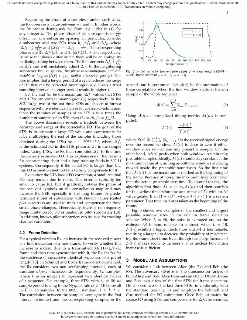
Fig. 4 shows an example of a sequence of length 2L = 8
samples. The more samples are used to estimate ∆ϕ, themore accurate the estimated FO is.
Fig. 4. Example of phase offset averaged over L = 4 si products.
1536−1233 (c) 2015 IEEE. Personal use is permitted, but republication/redistribution requires IEEE permission. Seehttp://www.ieee.org/publications_standards/publications/rights/index.html for more information.
This article has been accepted for publication in a future issue of this journal, but has not been fully edited. Content may change prior to final publication. Citation information: DOI10.1109/TMC.2015.2456916, IEEE Transactions on Mobile Computing
4
Regarding the phase of a complex number such as si,the Rx observes a value between −π and π. In other words,the Rx cannot distinguish ∆ϕ from ∆ϕ ± 2kπ in (4), forany integer k. The phase offset of 2π corresponds to 1
Ltsoffset, i.e., one subcarrier spacing. In particular, considera subcarrier and two FOs from it, ∆f1 and ∆f2, where|∆f1| ≤ 1
2Ltsand |∆f2| = |∆f1| + 1
Lts. The corresponding
phases are 2π|∆f1|Lts and 2π|∆f1|Lts + 2π, respectively.Because the phases differ by 2π, there will be an ambiguityin distinguishing between them. The Rx interprets ∆f1+
1Lts
as ∆f1 and will mistakenly adjust ∆f2 to the neighboringsubcarrier bin. In general, the phase is unambiguous and cor-rectable as long as |∆f | < 1
2Lts(half a subcarrier spacing). This
also implies that a longer period of a cycle reduces the rangeof FO that can be corrected unambiguously. Given a fixedsampling interval, a longer period results in higher L.
Let ths and thl be the maximum |∆f | values that STSsand LTSs can correct unambiguously, respectively. In the802.11a/g, two of the last three STSs are chosen to form asequence with two identical halves for coarse FO estimation.Since the number of samples of an LTS is four times thenumber of samples of an STS, then thl = ths/4 = f∆/2.
The above discussion reveals a tradeoff between theaccuracy and range of the correctable FO. The goal of theSTSs is to estimate a large FO value and compensate forit by multiplying the rest of the samples (including those
obtained during the LTSs) by e−j(−2π∆fs i ts), where ∆fsis the estimated FO in the STSs phase and i is the sample
index. Using LTSs, the Rx then computes ∆fl to fine-tunethe coarsely estimated FO. This explains one of the reasonsfor concatenating short and a long training fields in 802.11systems. Consequently, if the actual FO is larger than ths,this FO estimation method fails to fully compensate for it.
Even after the LTS-based FO correction, a small residualFO may remain due to noise. This error is typically toosmall to cause ICI, but it gradually rotates the phase ofthe received symbols on the constellation map and mayincrease the BER, specially in the long frames. A prede-termined subset of subcarriers with known values (calledpilot subcarrier) are used to track and compensate for thesesmall phase changes. Theoretically, there is no frequencyrange limitation for FO estimation in pilot subcarriers [13].In addition, known pilot subcarriers can be used for trackingchannel variations.
2.2 Frame Detection
For a typical wireless Rx, an increase in the received poweris a first indication of a new frame. To verify whether thisincrease is indeed due to a transmitted 802.11a/g/n/acframe and then time synchronize with it, the Rx checks forthe existence of successive identical sequences of a presetlength [15]. In Schmidl and Cox’s frame detection method,the Rx considers two non-overlapping intervals, each ofduration kλSTS microseconds (equivalently, kL samples,where k is an integer) to represent two identical halvesof a sequence. For example, three STSs with ts = 50 nssample period (owing to the Nyquist rate of 20 MHz) resultin L = 48 samples. In the 802.11 standard, 1 ≤ k ≤ 5.The correlation between the samples’ conjugate in the firstinterval (window) and the corresponding samples in the
0 15 30 45 60 75 90 105 120 135 150 1650
0.2
0.4
0.6
0.8
1
Sample index (n)
M(n
)
L = 16 L = 80
Fig. 5. M(n) vs. n for two extreme cases of window lengths (SNR =42 dB, frame starts at n = 31, ts = 50 ns).
second one is computed. Let A(n) be the summation ofthese correlations when the first window starts at the nthsample of the whole sequence:
A(n) =L−1∑
i=0
s∗n+isn+L+i. (5)
Using A(n), a normalized timing metric, M(n), is com-puted:
M(n) =|A(n)|2(E(n)
)2 (6)
where E(n) def=
∑L−1i=0 |sn+L+i|2 is the received signal energy
over the second window. M(n) is close to zero if eitherwindow does not contain any preamble sample. On theother hand,M(n) peaks when both windows contain onlypreamble samples. Ideally,M(n) should stay constant at themaximum value of 1, as long as both the windows are beingmoved inside the preamble boundaries. So the first timethatM(n) hits the maximum is marked as the beginning ofthe frame. Because of noise, the maximum may occur laterthan the actual preamble start time. To account for this, the
algorithm first finds M = maxnM(n) and then searches
for the earliest time before the occurrence of M with anMvalue greater than (1 − ǫ)M, where 0 < ǫ < 1 is a systemparameter. That time instant is taken as the beginning of theframe.
Fig. 5 shows two examples of the smallest and largestpossible window sizes in the 802.11a frame detectionscheme. When L = 80, the noise is averaged out, so the
estimate M is more reliable. In contrast, when L = 16,M(n) exhibits a higher fluctuation and M is less reliable,requiring a larger ǫ to decrease the probability of misdetect-ing the frame start time. Even though the sharp increase ofM(n) makes room to increase ǫ, it is unclear how muchincrease is sufficient.
3 MODEL AND ASSUMPTIONS
We consider a link between Alice (the Tx) and Bob (theRx). The adversary (Eve) is in the transmission ranges ofboth Alice and Bob. Alice transmits an 802.11 OFDM frameand Bob uses a few of the first STSs for frame detection.He chooses two of the last three STSs, in conformity withthe standard (see Fig. 3) and employs the Schmidl andCox method for FO estimation. Once Bob estimates thecoarse FO using STSs and compensates for ∆fs, he assumes,
1536−1233 (c) 2015 IEEE. Personal use is permitted, but republication/redistribution requires IEEE permission. Seehttp://www.ieee.org/publications_standards/publications/rights/index.html for more information.
This article has been accepted for publication in a future issue of this journal, but has not been fully edited. Content may change prior to final publication. Citation information: DOI10.1109/TMC.2015.2456916, IEEE Transactions on Mobile Computing
5
by default, that the residual FO is less than thl and thenestimates it using LTSs. According to the 802.11 standard,Bob does not perform any kind of boundary check duringthe LTS- and pilot-based FO estimation processes.
Eve aims at irrecoverably corrupting Alice’s frame at Bobusing the lowest possible jamming effort. Eve is aware ofthe PHY-layer protocol and the FO correction mechanismat Bob. She makes no assumptions about the channel pa-rameters or Alice’s transmission power. If the oscillatorsare either stable or accurate, Eve initially eavesdrops onAlice’s and Bob’s preamble transmissions (e.g., data-ACKexchanges) for a while. Through averaging, she estimatestheir FOs relative to Eve, denoted by ∆fae and ∆fbe,respectively2.
The metrics of interest are coarse and final estimated FOsat Bob, Symbol error rate (SER), the BER after demodulationbut before decoding, and the jamming effort (defined asthe jammer’s duty cycle [3]). These metrics will be studiedwith respect to the SNR, modulation scheme, and signal-to-jamming ratio (SJR) at Bob.
4 FREQUENCY OFFSET ESTIMATION ATTACK
In this section, we describe in detail an attack on the FOestimation. Eve launches this attack in two phases: (1)Eavesdropping on the channel to detect the start of Alice’sframe transmission and acquire its timing information; and(2) jamming the last three STSs of the preamble, which areused for coarse FO estimation.
4.1 Phase 1: Adaptive Fast Frame Detection
To pinpoint the last three STSs in time and corrupt the FOestimation at Bob, Eve must detect Alice’s frame and syn-chronize with its arrival at Bob. The detection should be fastenough to allow sufficient time for processing, switchingto transmission mode, and jamming the last three STSs.Referring to the frame detection mechanism in Section 2,Eve chooses the minimum possible window size (one STS,L = 16) and reduces the capture time to 2.5λSTS = 2 µs tomake sure that at least the first two STSs are captured.
To account for the higher detection inaccuracy due tothe small window size, Eve assumes that the actual starttime belongs to the first V = log2(L)
3 sample indicesi0, i1, . . . , iV−1 that are greater than (1−ǫ)M and finds all ofthem, instead of just looking for the first one. She sets ǫ to avalue less than 1/L, the contribution of a preamble samplepair in M(n). This is an attempt to exclude the sampleslocated more than one index before the actual frame starttime. If there are less than V sample values greater than thethreshold, Eve adaptively decreases the threshold by findingthe smallest ǫ that guarantees the existence of V candidates4.
2. In general, oscillators exhibit numerous instabilities, due to aging,temperature, acceleration, ionizing radiation, power supply voltage,etc. Thus, the Rx must update the FO estimate on a per-frame basis,even if the frame sender is already known. This is specially the casewith non-stable oscillators. In this case, Eve can perform FO estimationalong with fast frame detection to optimally design the jamming signalfor each frame (see Section 4.1).
3. The reason of this specific number will be explained in Sec-tion 4.2.3.
4. Eve may also apply the synchronization method in [18] to improvethe detection accuracy.
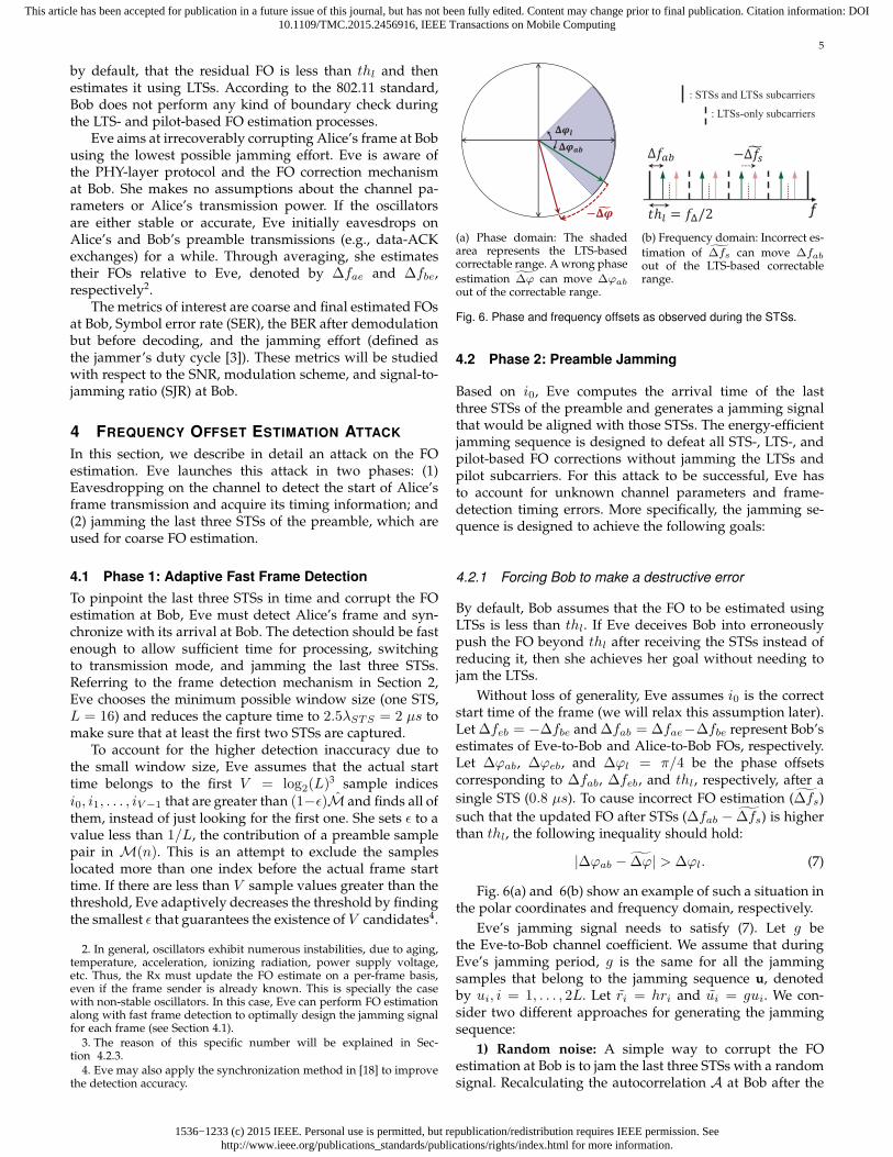
(a) Phase domain: The shadedarea represents the LTS-basedcorrectable range. A wrong phase
estimation ∆ϕ can move ∆ϕab
out of the correctable range.
f
: STSs and LTSs subcarriers
: LTSs-only subcarriers
(b) Frequency domain: Incorrect es-
timation of ∆fs can move ∆fabout of the LTS-based correctablerange.
Fig. 6. Phase and frequency offsets as observed during the STSs.
4.2 Phase 2: Preamble Jamming
Based on i0, Eve computes the arrival time of the lastthree STSs of the preamble and generates a jamming signalthat would be aligned with those STSs. The energy-efficientjamming sequence is designed to defeat all STS-, LTS-, andpilot-based FO corrections without jamming the LTSs andpilot subcarriers. For this attack to be successful, Eve hasto account for unknown channel parameters and frame-detection timing errors. More specifically, the jamming se-quence is designed to achieve the following goals:
4.2.1 Forcing Bob to make a destructive error
By default, Bob assumes that the FO to be estimated usingLTSs is less than thl. If Eve deceives Bob into erroneouslypush the FO beyond thl after receiving the STSs instead ofreducing it, then she achieves her goal without needing tojam the LTSs.
Without loss of generality, Eve assumes i0 is the correctstart time of the frame (we will relax this assumption later).Let ∆feb = −∆fbe and ∆fab = ∆fae−∆fbe represent Bob’sestimates of Eve-to-Bob and Alice-to-Bob FOs, respectively.Let ∆ϕab, ∆ϕeb, and ∆ϕl = π/4 be the phase offsetscorresponding to ∆fab, ∆feb, and thl, respectively, after a
single STS (0.8 µs). To cause incorrect FO estimation (∆fs)
such that the updated FO after STSs (∆fab − ∆fs) is higherthan thl, the following inequality should hold:
|∆ϕab − ∆ϕ| > ∆ϕl. (7)
Fig. 6(a) and 6(b) show an example of such a situation inthe polar coordinates and frequency domain, respectively.
Eve’s jamming signal needs to satisfy (7). Let g bethe Eve-to-Bob channel coefficient. We assume that duringEve’s jamming period, g is the same for all the jammingsamples that belong to the jamming sequence u, denotedby ui, i = 1, . . . , 2L. Let ri = hri and ui = gui. We con-sider two different approaches for generating the jammingsequence:
1) Random noise: A simple way to corrupt the FOestimation at Bob is to jam the last three STSs with a randomsignal. Recalculating the autocorrelation A at Bob after the
1536−1233 (c) 2015 IEEE. Personal use is permitted, but republication/redistribution requires IEEE permission. Seehttp://www.ieee.org/publications_standards/publications/rights/index.html for more information.
This article has been accepted for publication in a future issue of this journal, but has not been fully edited. Content may change prior to final publication. Citation information: DOI10.1109/TMC.2015.2456916, IEEE Transactions on Mobile Computing
6
superposition and ignoring the noise term in (2), we have:
Arandomdef=
L−1∑
i=0
si =L−1∑
i=0
(ri + ui)∗(rie
−j∆ϕab + uL+i)
=L−1∑
i=0
|ri|2e−j∆ϕab +L−1∑
i=0
ri∗uL+i
+L−1∑
i=0
u∗
i (rie−j∆ϕab + uL+i).
(8)
The phase and amplitude of the 2nd and 3rd terms in (8)
(and hence ∆ϕrandomdef= ∡Arandom) are unknown because not
only they include random complex numbers ui, but also thephase and amplitude of ri are unknown after traversing the
Alice-to-Bob channel. Hence, ∆ϕrandom may not satisfy (7),so FO jamming with a random signal cannot provide anyFO distortion guarantees to beat LTS-based FO estimation.
2) Fake preamble: A more effective jamming approachthat exploits both knowledge of the FO estimation algorithmand ∆fab is to construct a fake preamble with “identicalhalves”. For now, assume that the samples of the jammingsignal ui, i = 1, . . . , 2L can take any arbitrary value aslong as the signal conforms to the protocol bandwidthrequirement. The preamble phase warping attack in [10] isa special case of this approach, where the jamming signalis a random frequency-shifted version of an arbitrary fakepreamble. The advantage of having identical halves is thatwe can control and carefully calculate a desired FO for ubased on how Bob estimates ∆fab. Here, we also note thatthe channel response between Eve and Bob does not changethe FO. Before we explain how a desired FO (and hence∆feb) is determined, consider the superposition of Alice’ssignal and Eve’s jamming at Bob. Dropping the index ifrom (2) and ignoring the noise term, we have:
s = (r + u)∗(re−j∆ϕab + ue−j∆ϕeb) = e−j∆ϕab×[|r|2 + |u|2e−j(∆ϕeb−∆ϕab) + r∗ue−j(∆ϕeb−∆ϕab) + u∗r︸ ︷︷ ︸
B
].
(9)
Thus, the estimated phase offset at Bob is:
∆ϕ = ∡s = ∆ϕab + ∡B + ∡n. (10)
Note that the phase estimation error ϕedef= ∡B is a function
of SJR and ∆ϕeb, and jamming will have no effect if ϕe = 0.
Upon calculating ∆ϕ and ∆fs, Bob changes the FO for
the rest of the frame to ∆fab − ∆fs. According to (7), Eve issuccessful if she can ensure that ∆ϕeb satisfies the following:
|∆ϕab − ∆ϕ| > ∆ϕl ⇒ |ϕe + ∡n| > ∆ϕl =π
4. (11)
Eve can guarantee a desired ϕe only if SJR→ −∞. Oth-erwise, even if she knows ∆ϕab and u and can also control∆ϕeb, she has no control over other channel-dependentparameters in B. Specifically, the phase and amplitude ofr are channel-dependent and Eve cannot estimate the Alice-to-Bob channel coefficient h. That means that Eve is stillunable to guarantee a successful attack, which is also thecase in the preamble phase warping attack.
4.2.2 Designing a channel-independent jamming signal
To address the aforementioned challenge, Eve takes advan-tage of Alice’s known preamble samples and the productsum in (3) to cancel out the terms with unknown phases. Evefirst chooses L/2 non-overlapping pairs of samples. Withoutloss of generality, let Eve pair the samples in order and let(u1, u2) be the first pair of samples in the jamming sequence.By knowing the preamble sample values at Alice, u2 can bedesigned such that when Bob sums up s1 and s2, all theterms that depend on r (excluding |r|) in the term B in (9)are eliminated. Thus,
u2 = −r∗1r∗2
u1 (12)
which implies that
s1 + s2 = e−j∆ϕab×[|r1|2 + |r2|2 + (|u1|2 + |u2|2|) e−j(∆ϕeb−∆ϕab)
].
(13)
The requirement in (12) is similarly imposed on the restof the even samples. We refer to this requirement as thepairing rule. Accordingly, the autocorrelation function A forthis scheme, denoted by Afake, becomes:
Afake =L−1∑
i=0
si =
e−j∆ϕab
[ L−1∑
i=0
|ri|2 +L−1∑
i=0
|ui|2 e−j(∆ϕeb−∆ϕab)]
︸ ︷︷ ︸C(∆ϕeb−∆ϕab)
.(14)
Now Afake is a function of the difference between ∆ϕab
and ∆ϕeb only. So Eve can determine a desired value of∆ϕeb in a way that makes |∡C(∆ϕeb−∆ϕab)| > ∆ϕl, whichsatisfies (11).
4.2.3 Robustness to errors in frame start time
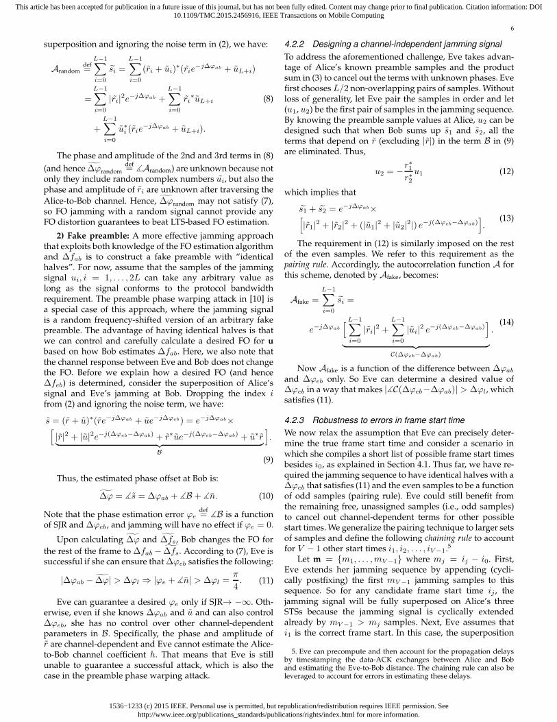
We now relax the assumption that Eve can precisely deter-mine the true frame start time and consider a scenario inwhich she compiles a short list of possible frame start timesbesides i0, as explained in Section 4.1. Thus far, we have re-quired the jamming sequence to have identical halves with a∆ϕeb that satisfies (11) and the even samples to be a functionof odd samples (pairing rule). Eve could still benefit fromthe remaining free, unassigned samples (i.e., odd samples)to cancel out channel-dependent terms for other possiblestart times. We generalize the pairing technique to larger setsof samples and define the following chaining rule to accountfor V − 1 other start times i1, i2, . . . , iV−1.5
Let m = {m1, . . . ,mV−1} where mj = ij − i0. First,Eve extends her jamming sequence by appending (cycli-cally postfixing) the first mV −1 jamming samples to thissequence. So for any candidate frame start time ij , thejamming signal will be fully superposed on Alice’s threeSTSs because the jamming signal is cyclically extendedalready by mV−1 > mj samples. Next, Eve assumes thati1 is the correct frame start. In this case, the superposition
5. Eve can precompute and then account for the propagation delaysby timestamping the data-ACK exchanges between Alice and Boband estimating the Eve-to-Bob distance. The chaining rule can also beleveraged to account for errors in estimating these delays.
1536−1233 (c) 2015 IEEE. Personal use is permitted, but republication/redistribution requires IEEE permission. Seehttp://www.ieee.org/publications_standards/publications/rights/index.html for more information.
This article has been accepted for publication in a future issue of this journal, but has not been fully edited. Content may change prior to final publication. Citation information: DOI10.1109/TMC.2015.2456916, IEEE Transactions on Mobile Computing
7
1 14132 116 155 164 7 8 93 10 12
1 14132 116 155 164 7 8 93 10 12
1 1311 155 7 93
1 135 9
1 9
1
1 14132 116 1554 7 8 93 10 1216
1 132 11654 7 8 93 10 1215 1614
1 2 11654 7 8 93 10 1214 15 1613
Jamming seed
Fig. 7. Cascaded chaining and pairing of the samples towards thejamming seed. Jamming samples are shown on the tree and the shiftedversions of Alice’s preamble on the bottom. Horizontal dashed linesrepresent direct dependency between samples.
of the jamming signal on Alice’s three STSs will be differentfrom the previous case (i.e., the jamming sequence is slidwith respect to Alice’s STSs) and (12) is no longer sufficientto eliminate the last two channel-dependent terms within Bin (9). Instead, Eve can find pairs of yet free samples and,similar to the pairing rule, define one of the samples of eachof such pairs based on the other sample of that pair andalso the corresponding samples in r. After this step, half ofthe free samples will be given values. Eve repeats the sameprocedure for the rest of the frame start times and free sam-ples. Based on these hierarchical dependencies among thesamples ui, Eve constructs a binary chaining tree in which thedependency between two samples is mapped to a parent-child relationship. Note that an unassigned (free) samplemay already have a chain of other dependent sample(s).The value of the dependents will be updated whenever thatsample takes a new value.
An example is depicted in Fig. 7 with m = {0, 1, 3, 4}.Without loss of generality, we assume Alice’s preamblesequence is shifted instead of the jamming sequence. Thetree in this figure shows how the jamming samples are beingchained together and used to construct the tree from thebottom to the top. A pair of free samples are considered assiblings. The left child specifies the value of its right siblingbased on mj and then the left child is copied to its parentnode. So the right child depends on its sibling. To explicitlydefine the dependency between the two sibling samples, alltheir dependent samples must also be taken into accountbecause their values in (9) are affected by their parents’values. For example, when j = 1, Eve may select two freesamples u1 and u3 (together with their dependents u2 andu4) to eliminate the channel-dependent terms:
u∗
1r16 + u∗
2r1 + u∗
3r2 + u∗
4r3 = 0 (15)
which implies the dependency of u3 to u1 (u2 and u4 aresubstituted by their corresponding pairing rule dependen-cies on u1 and u3):
u∗
3 = −r4(r2r16 − r1r1)
r2(r2r4 − r3r3)u∗
1. (16)
Now the value of the dependent of u3 (u4 in this example)is updated to maintain its dependency relationship with theright sibling u3.
Algorithm 1 Chaining and pairing rules combined
1: Input: L, V, r[1 . . . L],m[0 . . . V − 1]2: Initialize: u = 03: for j ← 1, V − 1 do4: k ← 2j
5: while k < L do6: t = circularly shifted r by mj
7: x = −∑ki=k−2j+1 uit
∗i /
∑k+2j
i=k+1 uit∗i
8: [uk, . . . , uk+2j−1] = [uk, . . . , uk+2j−1] ∗ x9: k = k + 2j+1
10: end while11: end for12: Return u
A pseudocode of the chaining rule, which also containsthe pairing rule, is provided in Algorithm 1. The algorithmiterates for each mj , j = 1, . . . , V − 1. At each iterationand for each pair of free samples, the right subtree (theright siblings of all its 2j − 1 dependents) is multiplied by acoefficient x (defined in line 8) such that the summationof the corresponding 2j product terms in (9) and the 2j
terms corresponding to the left subtree is zero. The hori-zontal arrows in Fig. 7 show the dependence of the rightsubtrees on their left subtrees. As a result, L/2j samplesare assigned at each iteration and the algorithm terminatesafter V = log2(L) iterations. In the end, all but one of thesamples (u1 in our example) will be a right sibling at leastonce at some point in the tree and so are assigned. We callthe remaining free sample the jamming seed, to which allthe samples are chained either directly or recursively. Thejamming seed can be used to control the jamming power.
4.3 Effects of LTSs on FO and Channel Estimation
LTSs are used for fine FO and channel estimation. As ex-plained in Section 2, the phase offset from the LTS-based FOcorresction perspective is between −π and π, which meansthat the true FO after STS-based correction has to be between−thl and thl. So LTSs can correct up to thl = f∆/2 FO, andany remaining phase offset will be an integer multiple of2π, which corresponds to 2k thl = kf∆, k = 1, 2, . . . . Inother words, the LTSs at Bob round up the FO manipulated
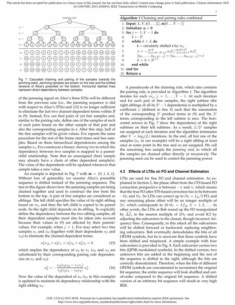
by ∆fs to the nearest multiple of 2thl and avoid ICI byadjusting the subcarriers to the closest, though incorrect, fre-quency bins. Consequently, in this attack all the subcarrierswill be shifted forward or backward, replacing neighbor-ing subcarriers. Bob eventually demodulates the bits of allOFDM symbols, but he is unaware that these symbols havebeen shifted and misplaced. A simple example with foursubcarriers is provided in Fig. 8. Each subcarrier carries twobits (QPSK-modulated symbols). In the shifted version, twounknown bits are added in the beginning and the rest ofthe sequence is shifted to the right, although the bits arecorrectly demodulated. Therefore, when the bits of differentOFDM symbols are concatenated to reconstruct the originalbit sequence, the entire sequence will look shuffled and out-of-order compared to the original bit sequence. A shiftedversion of an arbitrary bit sequence will result in very highBER.
1536−1233 (c) 2015 IEEE. Personal use is permitted, but republication/redistribution requires IEEE permission. Seehttp://www.ieee.org/publications_standards/publications/rights/index.html for more information.
This article has been accepted for publication in a future issue of this journal, but has not been fully edited. Content may change prior to final publication. Citation information: DOI10.1109/TMC.2015.2456916, IEEE Transactions on Mobile Computing
8
01 10 00 11 xx 01 10 00
Fig. 8. Example of the FO attack on four subcarriers (left): The attackshifts the subcarriers and the corresponding bits to the right.
An STS-based FO estimation error also affects the chan-nel estimation process, which is applied across the LTSs,specially if Bob estimates the channel irrespective to theoutcome of the fine FO estimation. To elaborate, the phaseoffset accumulates over time, causing different LTS samplesto have different phase offsets. However, Bob complacentlytries to interpret this time-varying phase offset as a fixed-value channel phasor by minimizing the MSE. Hence, hisattempt to model the FO as if it is a channel parameterresults in an incorrect estimated channel phasor, which afterequalization rotates the payload’s modulation symbols onthe constellation map.
4.4 Optimal Jamming Strategy (Optimal Jamming Se-
quence Design)
Let Φebdef= ∆ϕeb−∆ϕab. If the SJR at Bob is known, Eve can
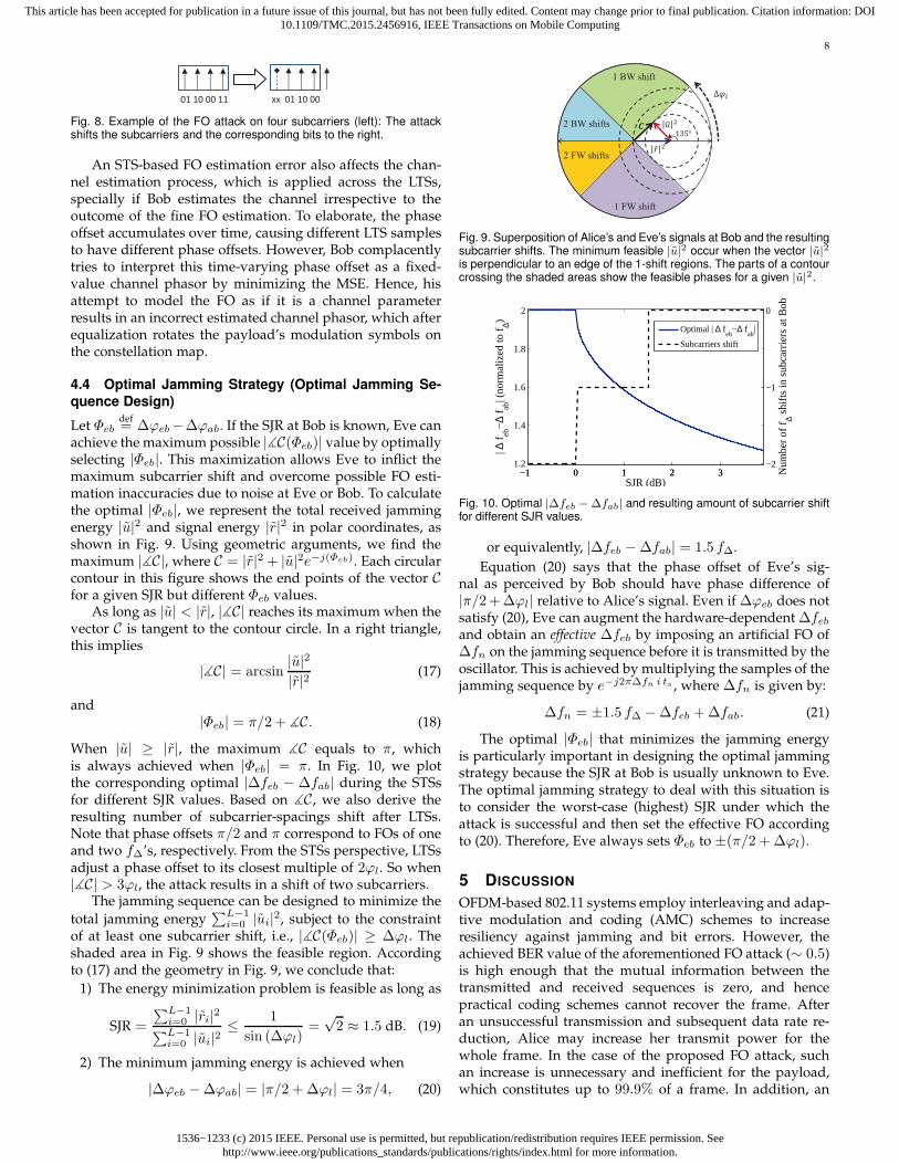
achieve the maximum possible |∡C(Φeb)| value by optimallyselecting |Φeb|. This maximization allows Eve to inflict themaximum subcarrier shift and overcome possible FO esti-mation inaccuracies due to noise at Eve or Bob. To calculatethe optimal |Φeb|, we represent the total received jammingenergy |u|2 and signal energy |r|2 in polar coordinates, asshown in Fig. 9. Using geometric arguments, we find themaximum |∡C|, where C = |r|2 + |u|2e−j(Φeb). Each circularcontour in this figure shows the end points of the vector Cfor a given SJR but different Φeb values.
As long as |u| < |r|, |∡C| reaches its maximum when thevector C is tangent to the contour circle. In a right triangle,this implies
|∡C| = arcsin|u|2|r|2 (17)
and|Φeb| = π/2 + ∡C. (18)
When |u| ≥ |r|, the maximum ∡C equals to π, whichis always achieved when |Φeb| = π. In Fig. 10, we plotthe corresponding optimal |∆feb − ∆fab| during the STSsfor different SJR values. Based on ∡C, we also derive theresulting number of subcarrier-spacings shift after LTSs.Note that phase offsets π/2 and π correspond to FOs of oneand two f∆’s, respectively. From the STSs perspective, LTSsadjust a phase offset to its closest multiple of 2ϕl. So when|∡C| > 3ϕl, the attack results in a shift of two subcarriers.
The jamming sequence can be designed to minimize the
total jamming energy∑L−1
i=0 |ui|2, subject to the constraintof at least one subcarrier shift, i.e., |∡C(Φeb)| ≥ ∆ϕl. Theshaded area in Fig. 9 shows the feasible region. Accordingto (17) and the geometry in Fig. 9, we conclude that:
1) The energy minimization problem is feasible as long as
SJR =
∑L−1i=0 |ri|2∑L−1i=0 |ui|2
≤ 1
sin (∆ϕl)=√2 ≈ 1.5 dB. (19)
2) The minimum jamming energy is achieved when
|∆ϕeb −∆ϕab| = |π/2 + ∆ϕl| = 3π/4, (20)
1 BW shift
2 FW shifts
2 BW shifts
1 FW shift
Fig. 9. Superposition of Alice’s and Eve’s signals at Bob and the resultingsubcarrier shifts. The minimum feasible |u|2 occur when the vector |u|2
is perpendicular to an edge of the 1-shift regions. The parts of a contourcrossing the shaded areas show the feasible phases for a given |u|2.
−1 0 1 2 31.2
1.4
1.6
1.8
2
SJR (dB)
| ∆ f
eb−
∆ f ab
| (no
rmal
ized
to f ∆)
−1 0 1 2 3−2
−1
0
Num
ber
of f ∆ s
hifts
in s
ubca
rrie
rs a
t Bob
Optimal | ∆ feb
−∆ fab
|
Subcarriers shift
Fig. 10. Optimal |∆feb −∆fab| and resulting amount of subcarrier shiftfor different SJR values.
or equivalently, |∆feb −∆fab| = 1.5 f∆.
Equation (20) says that the phase offset of Eve’s sig-nal as perceived by Bob should have phase difference of|π/2+∆ϕl| relative to Alice’s signal. Even if ∆ϕeb does notsatisfy (20), Eve can augment the hardware-dependent ∆feband obtain an effective ∆feb by imposing an artificial FO of∆fn on the jamming sequence before it is transmitted by theoscillator. This is achieved by multiplying the samples of thejamming sequence by e−j2π∆fn i ts , where ∆fn is given by:
∆fn = ±1.5 f∆ −∆feb +∆fab. (21)
The optimal |Φeb| that minimizes the jamming energyis particularly important in designing the optimal jammingstrategy because the SJR at Bob is usually unknown to Eve.The optimal jamming strategy to deal with this situation isto consider the worst-case (highest) SJR under which theattack is successful and then set the effective FO accordingto (20). Therefore, Eve always sets Φeb to ±(π/2 + ∆ϕl).
5 DISCUSSION
OFDM-based 802.11 systems employ interleaving and adap-tive modulation and coding (AMC) schemes to increaseresiliency against jamming and bit errors. However, theachieved BER value of the aforementioned FO attack (∼ 0.5)is high enough that the mutual information between thetransmitted and received sequences is zero, and hencepractical coding schemes cannot recover the frame. Afteran unsuccessful transmission and subsequent data rate re-duction, Alice may increase her transmit power for thewhole frame. In the case of the proposed FO attack, suchan increase is unnecessary and inefficient for the payload,which constitutes up to 99.9% of a frame. In addition, an
1536−1233 (c) 2015 IEEE. Personal use is permitted, but republication/redistribution requires IEEE permission. Seehttp://www.ieee.org/publications_standards/publications/rights/index.html for more information.
This article has been accepted for publication in a future issue of this journal, but has not been fully edited. Content may change prior to final publication. Citation information: DOI10.1109/TMC.2015.2456916, IEEE Transactions on Mobile Computing
9
intelligent jammer can track Alice’s power increase (e.g.,by overhearing management frames), adjust the jammingpower to always achieve the optimal SJR, and force thedropping of subsequent transmissions.
It may also be argued that because pilot subcarriersare transmitted on known frequencies, Bob can comparethe known symbols of the pilot subcarriers with the re-ceived symbols on different subcarriers to identify a possiblesubcarrier shift. However, because channel estimation isdistorted, locating the corrupted pilot subcarriers at Bobis quite challenging. Furthermore, these pilot subcarrierscannot be easily used for channel estimation (we leave theinvestigation of this problem to a future work).
Moreover, we note that jamming the LTSs after jammingthe STSs strengthens the attack by further distorting thechannel estimation process. However, jamming the LTSsalone cannot lead to a subcarrier shift even though it in-volves more jamming effort (8-µs duration on 48 subcarri-ers) than jamming three STSs (≤ 3 µs on 12 subcarriers).Furthermore, with LTSs jamming, pilot subcarriers can stillbe used to estimate the channel and correct any residual FO.
The system model in this paper assumes a single Tx-Rx-pair (i.e., Alice and Bob, and hence their FO, are known).In the case of multiple Tx-Rx pairs, Eve can construct adatabase of the FOs between different Tx-Rx pairs. Bene-fiting from CSMA/CA channel access mechanism, Eve canconsider one transmission at a time and then leverage pro-tocol semantics (e.g., data-ACK exchanges) to guess the Txand Rx of an upcoming transmission. Further investigationof this issue is left for future work.
6 PERFORMANCE EVALUATION
In this section, we evaluate the effectiveness of the FO esti-mation attack through simulations and USRP experiments.We implemented the 802.11a/g preamble (including bothshort and long training sequences) by extending the PHY-layer library functions of LabVIEW. Alice appends 1500modulated random bits to the frame preamble. Pilot-basedchannel and FO estimation and channel coding were notimplemented to concentrate on the specific effects of the FOattack on received uncoded bits. The impact of coding andpilot subcarriers was discussed in Section 5.
We assume that Bob uses the STSs t9 and t10, as definedin Fig. 3, for coarse FO estimation, followed by fine FO es-timation using LTSs. Channel estimation is performed overthe first LTS using the time domain method [13]. We firstevaluate the performance under a simulated AWGN chan-nel model and later in a multi-path indoor environment.(More results are provided in [19].) We vary the SJR, the SNR(noise level), the modulation scheme, and Eve’s effective FO,denoted by Deb. In particular, we consider BPSK, QPSK, and
16-QAM modulation schemes. We measure ∆fs as well asfinal estimated FO, SER, and BER.
We compare three cases: 1) jamming the last STSs with arandom signal (see Section 4.2.1), 2) FO attack with pairingrule only (V = 1 and L = 16 for frame detection), and 3)the entire FO attack including the chaining rule, with L = 16and V = log2 L. The purpose of evaluating the second caseis to study the impact of the chaining rule. The jammingduration for the second case is always equal to the sum of
10 20 30 40 500
0.2
0.4
0.6
0.8
1
SNR (dB)
Pro
b. o
f Pre
cise
Fra
me
Det
ectio
n at
Eve
Fast Frame Detection, 1st candidate
Fast Frame Detection, all 4 candidates
Default Frame Detection, 1st candidate
Fig. 11. Performance of different variants of frame detection vs. SNR(simulations).
the durations of t8 and t9. However, it is not constant whenthe chaining rule is applied, and depends on mV −1.
6.1 Simulations
We consider an AWGN channel model without signal at-tenuation. In our simulations, the SJR is normalized tothe energy of two full STSs. However, the chaining ruleresults in a variable-length cyclic postfix extension, whichsometimes has a slightly higher sample power than theaverage sample power over an STS.
6.1.1 Frame Detection and Jamming Duration
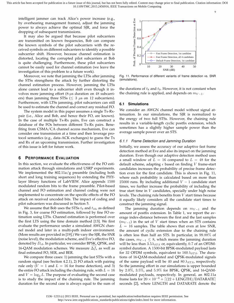
Initially, we assess the accuracy of our adaptive fast framedetection method at Eve and also its impact on the jammingduration. Even though our adaptive detection method usesa small window of L = 16 compared to L = 48 for thedefault scheme, adapting ǫ based on finding V frame-startcandidates increases the probability of precise frame detec-tion even for the first candidate. This is shown in Fig. 11,where each probability is calculated based on more than25000 runs. By including additional V − 1 candidate starttimes, we further increase the probability of including thetrue start time in V candidates, specially under high noiselevels. The chaining rule benefits from V start times becauseit equally likely considers all the candidate start times toconstruct the jamming signal.
The jamming duration depends on mV−1 and theamount of postfix extension. In Table 1, we report the av-erage index-distance between the first and the last samples(mV −1) in the set of V start times when an STS containsL = 16 samples. The table shows that even at low SNR,the amount of cyclic extension due to the chaining ruleis often less than half an STS. In particular, in 99.88% ofthe cases, mV −1 ≤ 8, which means the jamming durationwill be less than 3.5λSTS or, equivalently, 0.7 of an OFDM-symbol duration. A 1500-bit BPSK-modulated payload lastsfor 32 OFDM symbols, equivalent to 160λSTS . The dura-tions of 16-QAM-modulated and QPSK-modulated signalsof the same payload will be 40 and 80λSTS , respectively.So the jamming effort in our simulations is upper boundedby 2.0%, 3.5%, and 5.9% for BPSK, QPSK, and 16-QAM-modulated payloads, respectively. In general, an 802.11aframe lasts for 20× 10−6 + ⌈(22+ LENGTH)/DATARATE⌉seconds [2], where LENGTH and DATARATE denote the
1536−1233 (c) 2015 IEEE. Personal use is permitted, but republication/redistribution requires IEEE permission. Seehttp://www.ieee.org/publications_standards/publications/rights/index.html for more information.
This article has been accepted for publication in a future issue of this journal, but has not been fully edited. Content may change prior to final publication. Citation information: DOI10.1109/TMC.2015.2456916, IEEE Transactions on Mobile Computing
10
0 0.5 1 1.5 2−0.4
−0.2
0
0.2
0.4
0.6
Effective FO Deb
(normalized to f∆)
E[∆
fs](normalized
tof∆)
w/ chaining
w/o chaining
(a) Impact of the effective Eve-to-Bob FOon the performance of the coarse FO esti-mation (SJR = 1.59 dB and SNR = 25 dB).
−50 −40 −30 −20 −10
0
0.1
0.2
0.3
0.4
0.5
Noise power (dBm)
E[∆
fs](normalized
tof∆)
w/ chaining
w/o chaining
Random FO jammer
(b) Impact of the noise level on the perfor-mance of the FO attack (SJR = 1.59 dB andDeb = 1.52 f∆).
0 0.5 1 1.5 2
0
0.2
0.4
0.6
0.8
1
Effective FO Deb
(normalized to f∆)
Est
imat
ed F
O a
t Bob
(no
rmal
ized
to f
∆)
w/ chaining
w/o chaining
(c) Impact of the effective Eve-to-Bob FOon the estimated FO at Bob (SJR = 1.3 dBand SNR = 25 dB).
−0.5 0 0.5 1 1.5 2 2.5
0
0.2
0.4
0.6
0.8
1
SJR (dB)
Est
imat
ed F
O a
t Bob
(no
rmal
ized
to f
∆)
w/ chaining
w/o chaining
Random FO jammer
(d) Impact of SJR on the estimated FO atBob (SNR = 25 dB and Deb = 1.52 f∆).
0 0.5 1 1.5 20
0.2
0.4
0.6
0.8
1
Effective FO Deb
(normalized to f∆)
SE
R
BPSK
QPSK
16−QAM
(e) SER performance for different modu-lation schemes (SJR = 1.59 dB and SNR= 30 dB).
0 0.5 1 1.5 20
0.1
0.2
0.3
0.4
0.5
Effective FO Deb
(normalized to f∆)
BE
R
BPSK
QPSK
16−QAM
(f) BER performance for different modula-tion schemes (SJR= 1.59 dB and SNR =30 dB).
Fig. 12. Performance of different variants of the FO attack and of random FO jamming under different noise levels, Deb and SJR values, andmodulation schemes. The transmission power is 0 dBm. (simulation results)
encoded payload size (in bits) and the data rate, respectively.For a typical 802.11a frame [3], the jamming effort variesbetween 0.07% and 0.88%, depending on the code and datarates. This is 30% less than the effort of the OFDM symboljamming attack in [3].
SNR (dB) 5 10 15 20 25 30E(mV −1) 4.05 3.74 3.54 3.23 3.02 3.0
TABLE 1Average value of mV −1 in the chaining rule for different SNR levels.
6.1.2 FO Estimation
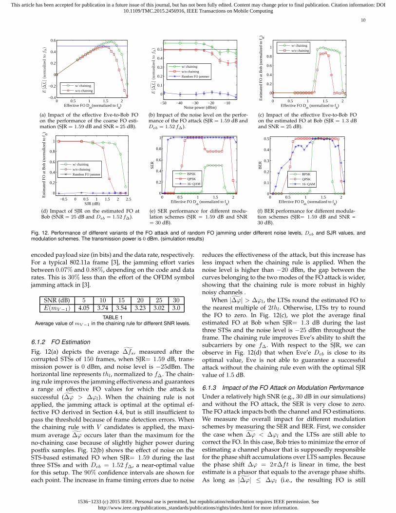
Fig. 12(a) depicts the average ∆fs, measured after thecorrupted STSs of 150 frames, when SJR= 1.59 dB, trans-mission power is 0 dBm, and noise level is −25dBm. Thehorizontal line represents thl, normalized to f∆. The chain-ing rule improves the jamming effectiveness and guaranteesa range of effective FO values for which the attack is
successful (∆ϕ > ∆ϕl). When the chaining rule is notapplied, the jamming attack is optimal at the optimal ef-fective FO derived in Section 4.4, but is still insufficient topass the threshold because of frame detection errors. Whenthe chaining rule with V candidates is applied, the maxi-
mum average ∆ϕ occurs later than the maximum for theno-chaining case because of slightly higher power duringpostfix samples. Fig. 12(b) shows the effect of noise on theSTS-based estimated FO when SJR= 1.59 during the lastthree STSs and with Deb = 1.52 f∆, a near-optimal valuefor this setup. The 90% confidence intervals are shown foreach point. The increase in frame timing errors due to noise
reduces the effectiveness of the attack, but this increase hasless impact when the chaining rule is applied. When thenoise level is higher than −20 dBm, the gap between thecurves belonging to the two modes of the FO attack is wider,showing that the chaining rule is more robust in highlynoisy channels .
When |∆ϕ| > ∆ϕl, the LTSs round the estimated FO tothe nearest multiple of 2thl. Otherwise, LTSs try to roundthe FO to zero. In Fig. 12(c), we plot the average finalestimated FO at Bob when SJR= 1.3 dB during the lastthree STSs and the noise level is −25 dBm throughout theframe. The chaining rule improves Eve’s ability to shift thesubcarriers by one f∆. With respect to the SJR, we canobserve in Fig. 12(d) that when Eve’e Deb is close to itsoptimal value, Eve is not able to guarantee a successfulattack without the chaining rule even with the optimal SJRvalue of 1.5 dB.
6.1.3 Impact of the FO Attack on Modulation Performance
Under a relatively high SNR (e.g., 30 dB in our simulations)and without the FO attack, the SER is very close to zero.The FO attack impacts both the channel and FO estimations.We measure the overall impact for different modulationschemes by measuring the SER and BER. First, we consider
the case when ∆ϕ < ∆ϕl and the LTSs are still able tocorrect the FO. In this case, Bob tries to minimize the error ofestimating a channel phasor that is supposedly responsiblefor the phase shift accumulations over LTS samples. Becausethe phase shift ∆ϕ = 2π∆ft is linear in time, the bestestimate is a phasor that equals to the average phase shifts.
As long as |∆ϕ| ≤ ∆ϕl (i.e., the resulting FO is still

1536−1233 (c) 2015 IEEE. Personal use is permitted, but republication/redistribution requires IEEE permission. Seehttp://www.ieee.org/publications_standards/publications/rights/index.html for more information.
This article has been accepted for publication in a future issue of this journal, but has not been fully edited. Content may change prior to final publication. Citation information: DOI10.1109/TMC.2015.2456916, IEEE Transactions on Mobile Computing
11
less than thl), the maximum phase offset between the firstand last samples in an LTS is π, which implies that theerror in phasor estimation is always less than π/2. On theconstellation map, This error will cause an identical rotationof all the payload’s modulated samples [1]. We select toapply channel estimation to one LTS to limit the amount ofrotation. Fig. 12(e) shows the SER for different modulationschemes. Clearly, BPSK is the most resilient scheme against
channel phasor estimation error. Once |∆ϕ| > ∆ϕl and thesubcarriers are shifted, the sequence of modulated samplesof any modulation scheme looks random relative to itsoriginal sequence, resulting in the highest possible SER, i.e.,(|M | − 1)/|M |, where |M | is the modulation order.
The BER under higher-order modulation schemes, how-ever, is less affected by the attack if the subcarriers are notshifted but the symbols are rotated to neighboring regions,as shown in Fig. 12(f). With the increase of Deb, first the BERof 16-QAM starts to increase due to symbol errors. However,once QPSK also experiences symbol errors, its BER willbe larger than the one for 16-QAM. Because of the Graycode structure, higher-order modulations guarantee lowerBER when one of the neighboring symbols is mistakenlydemodulated instead of the true symbol. Nonetheless, aslong as the FO attack shifts the subcarriers, the BER stays atits maximum (0.5), irrespective of the modulation scheme.
6.2 USRP Experiments
We experimentally evaluate the impact of the proposedFO attack using an NI-USRP 2922 testbed, operated in anindoor environment in the 2.4 GHz band and controlled byWindows-based hosts. Our setup consists of three USRPs,acting as Alice, Bob, and Eve. To estimate the FOs betweenthe USRPs, we connected Alice and Eve devices to Bobthrough an SMA cable and conduct 4000 FO estimations.∆fab and ∆feb were measured to be 1086 and 340 Hz withstandard deviations of 270 and 230 Hz, respectively. Basedon the estimated FOs, effective FO Deb was approximatelyfound to be 715.5 + ∆fn Hz with standard deviation of355 Hz. In our experiments, we fix the locations of Aliceand Bob and move Eve to create two scenarios: LOS andnon-LOS (see Table 2). In the non-LOS case, a metal shelf isplaced between Eve and the other two. At each location,Eve launches the attack with different jamming powersand different values of ∆fn. In the experiments, Alice’stransmission power is set to 7.9 dBm.
Scenario Alice-Bob Eve-Alice Eve-BobLOS 1.5 m 1.77 m 1.77 m
NLOS 1.5 m 4.74 m 5.15 m
TABLE 2Distances between Alice, Bob, and Eve for two different scenarios.
The USRP-based implementation of our reactive attackfaced two challenges. First, the internal buffer size of theUSRPs, which is used to store the samples before forwardingthem to the host PC, is not big enough to store the samplescaptured at the nominal rate of 20 MHz. So we had toreduce the symbol rate to 0.2 MSPS. As a consequence, λSTS
expanded to 80 µs and f∆ dropped to 3125 Hz (i.e., thetotal bandwidth of 200 kHz). Second, the USRP’s reaction
4000 5000 6000 7000
1000
2000
3000
4000
∆f n (Hz)
E[∆
fs](H
z)
6.15 dBm
6.85 dBm
7.95 dBm
8.9 dBm
10 dBm
(a) Effect of ∆fn on STS-based FOestimation with different jammingpowers.
−6 −4 −2 0 2 4 6 80
50
100
150
200
Num
ber
of A
ttack
s
Estimated Frequency Offset (kHz)
After LTS−based estimation
Before LTS−based estimation
(b) Effect of LTS-based FO estima-tion on ∆fs (∆fn = 7000 Hz andjamming power = 8.9 dBm).
Fig. 13. USRP results: Performance of the FO attack in LOS scenario.
time (which consists of the communication delay between aUSRP and its host PC through an Ethernet cable, the host’sprocessing delay, and the time to initialize for transmission)exceeded several milliseconds. So Eve will miss the restof the frame before she starts her jamming6. To overcomethese challenges, we made the following modification inthe implementation. We let Alice send several back-to-backframes periodically with a known period of T ms. Uponbeing triggered by a received power increase, Eve captures2 µs worth of the sequence. If a frame is detected, sheassumes that the next frame starts exactly T ms after thestart of the this one. The host PC at Eve then constructs ajamming signal based on the timing information of the firstdetected frame and sends it to the USRP. After initialization,the USRP’s onboard timer, which has nanosecond accuracy,waits for the remaining time before the next frame arrival.Once the timer expires, the device starts jamming the pream-ble of the new frame and other subsequent frames.
Fig. 13(a) shows the average STS-based estimation of∆fab in the LOS scenario for different values of ∆fn andjamming powers. Because our USRPs do not have stableoscillators and hence ∆fab varies with time, we representthe probable value of ∆fab + f∆/2 by a shaded area whoseheight is twice the standard deviation of ∆fab. Eve is able
to shift the subcarriers by pushing ∆fs beyond the actualvalue of ∆fab + f∆/2. The results show that even thoughEve-Bob distance is larger than Alice-Bob distance, Eve canshift the subcarriers using almost the same power as Alice’spower if ∆fn is optimally selected. In particular, when thejamming signal is 7.95 dBm, Eve is successful in shiftingthe subcarreirs in 84% of the attacks if ∆fn = 5500 Hz.This validates our optimal ∆fn selection scheme (see Sec-tion 4.4) since the “estimated” optimal ∆fn in our setup is715.5+4687.5 = 5403 Hz. After STSs, LTS-based estimationrounds the FO to the nearest multiple of f∆. In Fig. 13(b),we depict a histogram to show/compare the number of jam-ming attacks that result in different ranges of FO estimatesat Bob, before and after LTS-based estimation. It shows howLTSs can complacently exacerbate the FO estimation error.We show the results for the NLOS scenario in Fig. 14(a). Asseen in this figure, the lower the jamming power, the smalleris the optimal value of ∆fn, which is inline with Fig. 10.
In the above results, we notice that the 95% confidenceintervals at higher ∆fn values are noticeably larger than
6. This is not the case for an off-the-shelf reactive jammer, whichusually has an onboard processor and dedicated hardware. In addition,implementing a correlation-based reactive jammer on the USRP’s FPGAcan achieve a reaction time of 2.56 µs [20].
1536−1233 (c) 2015 IEEE. Personal use is permitted, but republication/redistribution requires IEEE permission. Seehttp://www.ieee.org/publications_standards/publications/rights/index.html for more information.
This article has been accepted for publication in a future issue of this journal, but has not been fully edited. Content may change prior to final publication. Citation information: DOI10.1109/TMC.2015.2456916, IEEE Transactions on Mobile Computing
12
4000 5000 6000 7000
1000
2000
3000
4000
∆fn (Hz)
E[∆
fs](H
z)
12.1 dBm
13.1 dBm
14.2 dBm
14.9 dBm
16 dBm
(a) Effect of ∆fn on STS-based FOestimation with different jammingpowers.
4000 5000 6000 70000
20
40
60
80
100
∆fn (Hz)
% o
f Atta
cks
2 shifts F/W
1 shift F/W
No shift
1 shift B/W
2 shifts B/W
(b) Effect of ∆fn on the amount ofsubcarrier shifts (jamming power =14.2 dBm).
12 13 14 15 160
20
40
60
80
100
Jamming Power (dBm)
% o
f Atta
cks
2 shifts F/W
1 shift F/W
No shift
1 shift B/W
2 shifts B/W
(c) Effect of jamming power on theamount of subcarrier shifts (∆fn =7000 Hz).
11 12 13 14 15 160
1000
2000
3000
4000
5000
Jamming Power (dBm)
E[∆
fs](H
z)
w/ chaining
w/o chaining
Random FO jammer
(d) Performance of different vari-ants of the FO attack vs. jammingpower (∆fn = 5700Hz).
Fig. 14. USRP results: Performance of the FO attack in the NLOS scenario. Alice’s signal power is 7.9 dBm.
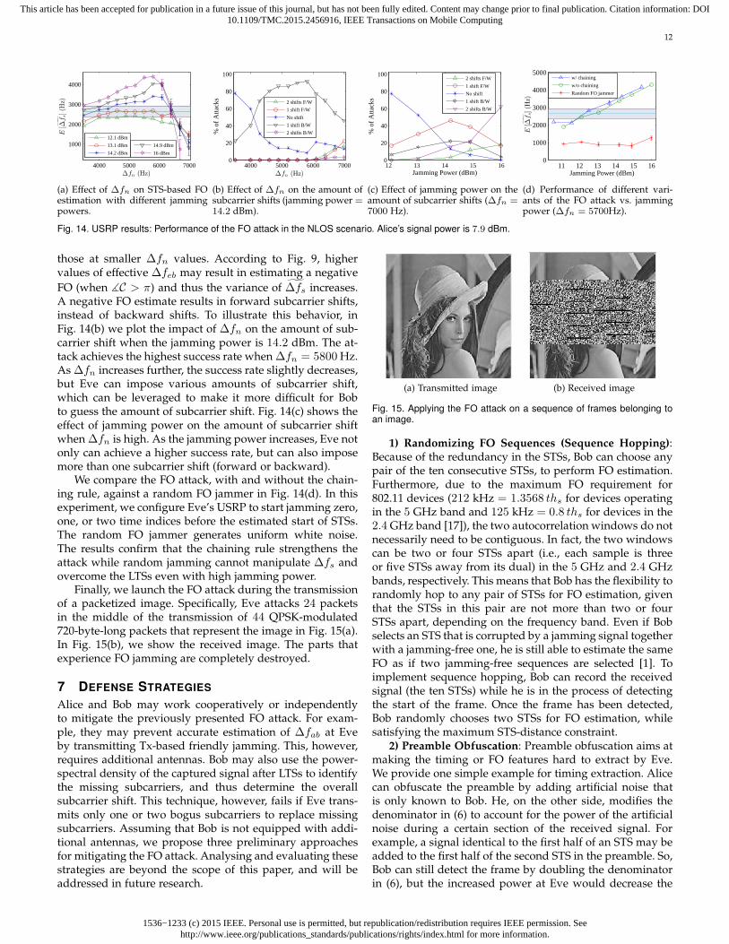
those at smaller ∆fn values. According to Fig. 9, highervalues of effective ∆feb may result in estimating a negative
FO (when ∡C > π) and thus the variance of ∆fs increases.A negative FO estimate results in forward subcarrier shifts,instead of backward shifts. To illustrate this behavior, inFig. 14(b) we plot the impact of ∆fn on the amount of sub-carrier shift when the jamming power is 14.2 dBm. The at-tack achieves the highest success rate when ∆fn = 5800 Hz.As ∆fn increases further, the success rate slightly decreases,but Eve can impose various amounts of subcarrier shift,which can be leveraged to make it more difficult for Bobto guess the amount of subcarrier shift. Fig. 14(c) shows theeffect of jamming power on the amount of subcarrier shiftwhen ∆fn is high. As the jamming power increases, Eve notonly can achieve a higher success rate, but can also imposemore than one subcarrier shift (forward or backward).
We compare the FO attack, with and without the chain-ing rule, against a random FO jammer in Fig. 14(d). In thisexperiment, we configure Eve’s USRP to start jamming zero,one, or two time indices before the estimated start of STSs.The random FO jammer generates uniform white noise.The results confirm that the chaining rule strengthens theattack while random jamming cannot manipulate ∆fs andovercome the LTSs even with high jamming power.
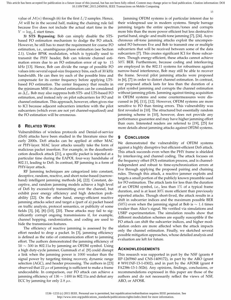
Finally, we launch the FO attack during the transmissionof a packetized image. Specifically, Eve attacks 24 packetsin the middle of the transmission of 44 QPSK-modulated720-byte-long packets that represent the image in Fig. 15(a).In Fig. 15(b), we show the received image. The parts thatexperience FO jamming are completely destroyed.
7 DEFENSE STRATEGIES
Alice and Bob may work cooperatively or independentlyto mitigate the previously presented FO attack. For exam-ple, they may prevent accurate estimation of ∆fab at Eveby transmitting Tx-based friendly jamming. This, however,requires additional antennas. Bob may also use the power-spectral density of the captured signal after LTSs to identifythe missing subcarriers, and thus determine the overallsubcarrier shift. This technique, however, fails if Eve trans-mits only one or two bogus subcarriers to replace missingsubcarriers. Assuming that Bob is not equipped with addi-tional antennas, we propose three preliminary approachesfor mitigating the FO attack. Analysing and evaluating thesestrategies are beyond the scope of this paper, and will beaddressed in future research.
(a) Transmitted image (b) Received image
Fig. 15. Applying the FO attack on a sequence of frames belonging toan image.
1) Randomizing FO Sequences (Sequence Hopping):Because of the redundancy in the STSs, Bob can choose anypair of the ten consecutive STSs, to perform FO estimation.Furthermore, due to the maximum FO requirement for802.11 devices (212 kHz = 1.3568 ths for devices operatingin the 5 GHz band and 125 kHz = 0.8 ths for devices in the2.4 GHz band [17]), the two autocorrelation windows do notnecessarily need to be contiguous. In fact, the two windowscan be two or four STSs apart (i.e., each sample is threeor five STSs away from its dual) in the 5 GHz and 2.4 GHzbands, respectively. This means that Bob has the flexibility torandomly hop to any pair of STSs for FO estimation, giventhat the STSs in this pair are not more than two or fourSTSs apart, depending on the frequency band. Even if Bobselects an STS that is corrupted by a jamming signal togetherwith a jamming-free one, he is still able to estimate the sameFO as if two jamming-free sequences are selected [1]. Toimplement sequence hopping, Bob can record the receivedsignal (the ten STSs) while he is in the process of detectingthe start of the frame. Once the frame has been detected,Bob randomly chooses two STSs for FO estimation, whilesatisfying the maximum STS-distance constraint.
2) Preamble Obfuscation: Preamble obfuscation aims atmaking the timing or FO features hard to extract by Eve.We provide one simple example for timing extraction. Alicecan obfuscate the preamble by adding artificial noise thatis only known to Bob. He, on the other side, modifies thedenominator in (6) to account for the power of the artificialnoise during a certain section of the received signal. Forexample, a signal identical to the first half of an STS may beadded to the first half of the second STS in the preamble. So,Bob can still detect the frame by doubling the denominatorin (6), but the increased power at Eve would decrease the
1536−1233 (c) 2015 IEEE. Personal use is permitted, but republication/redistribution requires IEEE permission. Seehttp://www.ieee.org/publications_standards/publications/rights/index.html for more information.
This article has been accepted for publication in a future issue of this journal, but has not been fully edited. Content may change prior to final publication. Citation information: DOI10.1109/TMC.2015.2456916, IEEE Transactions on Mobile Computing
13
value ofM(n) through (6) for the first L/2 samples. Hence,
M will be in the second half, making the chaining rule failbecause Eve does not include the actual start time in theV = log2 L start times.
3) STS Bypassing: Bob can simply disable the STS-based FO estimation mechanism to dodge the FO attack.However, he still has to meet the requirement for coarse FOestimation, i.e., unambiguous phase estimation (see Section2.1). Under BPSK modulation, which is typically used totransmit the PHY header, Bob can tolerate channel esti-mation errors due to an FO estimation error of up to 15kHz [13]. Hence, Bob can divide the range of possible FOvalues into several equal-size frequency bins, each of 30 kHzbandwidth. He can then try each of the possible bins andcompensate for its center frequency before applying LTS-based FO estimation. The center frequency that results inthe minimum MSE in channel estimation can be consideredas ∆fs. Bob may also suppress both STS- and LTS-based FOestimation, and instead rely on pilot subcarriers for FO andchannel estimation. This approach, however, often gives riseto ICI because adjacent subcarriers interfere with the pilotsubcarriers (which even are not yet channel-equalized) andthe FO estimation will be erroneous.
8 RELATED WORK
Vulnerabilities of wireless protocols and Denial-of-service(DoS) attacks have been studied in the literature since theearly 2000s. DoS attacks can be applied at either MACor PHY-layer. MAC layer attacks usually take the form ofmalicious packet insertion. For example, in the deauthenti-cation deadlock attack [21], a specific packet is injected at aparticular time during the EAPOL four-way handshake of802.11, leading to DoS. In contrast, RF jamming is a form ofPHY-layer attack.
RF Jamming techniques are categorized into constant,deceptive, random, reactive, and short noise-based (narrow-band) intelligent jamming methods [4], [22]. Constant, de-ceptive, and random jamming models achieve a high levelof DoS by excessively transmitting over the channel, butexhibit poor energy efficiency and high detection prob-ability [22]. On the other hand, energy-efficient reactivejamming attacks select and target a (part of a) packet basedon traffic analysis, protocol semantics, or publicity of somefields [3], [4], [8]–[10], [20]. These attacks may fail to sig-nificantly corrupt ongoing transmissions if, for example,channel hopping, randomization, and coding are used tohide the transmission features.
The efficiency of reactive jamming is assessed by theeffort needed to drop a packet. In [3], jamming efficiencyis defined as the ratio of communication effort to jammingeffort. The authors demonstrated the jamming efficiency of50 ∼ 500 in 802.11a by jamming an OFDM symbol. Usinga high duty-cycle jammer, Gummadi et al. [9] could disrupta link when the jamming power is 1000 weaker than thesignal power by targeting timing recovery, dynamic rangeselection (AGC), and header processing. The authors in [23]observed that 22 µs of jamming is sufficient to make a frameundecodable. In comparison, our FO attack can achieve ajamming efficiency of 136 ∼ 1400 in 802.11a and defeat anyECC by jamming for only 2.8 µs.
Jamming OFDM systems is of particular interest due totheir widespread use in modern systems. Simple barragejamming targets the entire spectrum/tones and corruptsmore bits than the more power efficient but less destructivepartial band, single- and multi-tone jamming [7], [24]. Asyn-chronous off-tone jamming attacks exploit the uncompen-sated FO between Eve and Bob to transmit one or multiplesubcarriers that will be received between some of the datasubcarriers [7]. This creates significant ICI for those subcar-riers. Though energy-efficient, these attacks cannot achieve50% BER. Furthermore, because coding and interleavingare employed in the 802.11 systems for robustness againstnarrow-band interference, Bob may still be able to recoverthe frame. Several pilot jamming attacks were proposedin [6], [7] in order to distort channel estimation. In contrast,our proposed attack lasts for less than the duration of apilot symbol jamming and corrupts the channel estimationwithout jamming pilots. Jamming against timing acquisitionin OFDM systems and some countermeasures were dis-cussed in [8], [11], [12]. However, OFDM systems are moresensitive to FO than timing errors. This vulnerability wasfirst revealed in [10]. The structured but essentially randomjamming scheme in [10], however, does not provide anyperformance guarantee and may have higher jamming effortthan ours. Interested readers are referred to [19], [25] formore details about jamming attacks against OFDM systems.
9 CONCLUSION
We demonstrated the vulnerability of OFDM systemsagainst a highly disruptive but efficient-efficient DoS attack.This attack succeeds even when the PHY frame is shieldedby interleaving and channel coding. The attack focuses onthe frequency offset (FO) estimation process, and is channel-independent and robust to time-synchronization errors atEve through applying the proposed pairing and chainingrules. Through this attack, a reactive jammer exploits andtargets a small portion of the publicly known preamble usedfor FO estimation. The attack lasts for less than the durationof an OFDM symbol, i.e., less than 1% of a typical frameduration, and is at least 30% more efficient than previouslyreported attacks. Though short-lived, the attack results in ashift in subcarrier indices and the maximum possible BER(50%) even when the jamming signal at Bob is ∼ 1.4 timesweaker than Alice’s signal. We verified via simulations andUSRP experimentation. The simulation results show thatdifferent modulation schemes are equally susceptible if theFO attack can shift the subcarrier indices, and higher mod-ulation orders are more affected when the attack impactsonly the channel estimation. Finally, we sketched severalpossible mitigation approaches, whose detailed analysis andevaluation are left for future.
ACKNOWLEDGEMENTS
This research was supported in part by the NSF (grants #IIP-1265960 and CNS-1409172), in part by the ARO (grant# W911NF-13-1-0302), and in part by the AFOSR (grant #FA2386-13-1-3026). Any opinions, findings, conclusions, orrecommendations expressed in this paper are those of theauthors and do not necessarily reflect the views of NSF,ARO, or AFOSR.

1536−1233 (c) 2015 IEEE. Personal use is permitted, but republication/redistribution requires IEEE permission. Seehttp://www.ieee.org/publications_standards/publications/rights/index.html for more information.
This article has been accepted for publication in a future issue of this journal, but has not been fully edited. Content may change prior to final publication. Citation information: DOI10.1109/TMC.2015.2456916, IEEE Transactions on Mobile Computing
14
REFERENCES
[1] H. Rahbari, M. Krunz, and L. Lazos, “Security vulnerability andcountermeasures of frequency offset correction in 802.11a sys-tems,” in Proc. IEEE INFOCOM’14, Toronto, ON, Canada, Apr.2014, pp. 1015–1023.
[2] “IEEE Std 802.11a-1999,” Supplement to IEEE Standard for Infor-mation Technology— Telecommunications and Information ExchangeBetween Systems—Local and Metropolitan Area Networks—SpecificRequirements: Part 11: Wireless LAN Medium Access Control (MAC)and Physical Layer (PHY) Specifications: High-Speed Physical Layer inthe 5 GHz Band, 1999.
[3] G. Lin and G. Noubir, “On link layer denial of service in datawireless LANs,” Wireless Communications and Mobile Computing,vol. 5, no. 3, pp. 273–284, 2005.
[4] K. Pelechrinis, M. Iliofotou, and S. Krishnamurthy, “Denial of ser-vice attacks in wireless networks: The case of jammers,” Commun.Surveys Tuts., vol. 13, no. 2, pp. 245–257, 2011.
[5] M. Strasser, B. Danev, and S. Capkun, “Detection of reactivejamming in sensor networks,” ACM Trans. Sensor Networks, vol. 7,no. 2, pp. 16:1–16:29, Aug. 2010.
[6] T. C. Clancy, “Efficient OFDM denial: Pilot jamming and pilotnulling,” in Proc. IEEE Int. Conf. Commun. (ICC’11), Kyoto, Japan,Jun. 2011.
[7] C. Shahriar, S. Sodagari, R. McGwier, and T. Clancy, “Performanceimpact of asynchronous off-tone jamming attacks against OFDM,”in Proc. IEEE Int. Conf. Commun. (ICC’13), Budapest, Hungary, Jun.2013, pp. 2177–2182.
[8] M. J. LaPan, T. C. Clancy, and R. W. McGwier, “Physicallayer orthogonal frequency-division multiplexing acquisition andtiming synchronization security,” Wireless Communications andMobile Computing, 2014, to be published. [Online]. Available:http://dx.doi.org/10.1002/wcm.2500
[9] R. Gummadi, D. Wetherall, B. Greenstein, and S. Seshan, “Under-standing and mitigating the impact of RF interference on 802.11networks,” in Proc. ACM SIGCOMM’07, Kyoto, Japan, 2007, pp.385–396.
[10] M. J. LaPan, T. C. Clancy, and R. W. McGwier, “Phase warping anddifferential scrambling attacks against OFDM frequency synchro-nization,” in Proc. IEEE Int. Conf. Acoust., Speech, Signal Process.(ICASSP’13), Vancouver, BC, Canada, May 2013, pp. 2886–2890.
[11] C. Mueller-Smith and W. Trappe, “Efficient OFDM denial in theabsence of channel information,” in Proc. Military Commun. Conf.(MILCOM’13), San Diego, CA, USA, Nov. 2013, pp. 89–94.
[12] L. Sanguinetti, M. Morelli, and H. Poor, “Frame detection andtiming acquisition for OFDM transmissions with unknown inter-ference,” IEEE Trans. Wireless Commun., vol. 9, no. 3, pp. 1226–1236,Mar. 2010.
[13] J. Heiskala and J. Terry, OFDM Wireless LANs: A Theoretical andPractical Guide. SAMS Publishing Indianapolis, 2002.
[14] L. Weng, R. Murch, and V. Lau, “SISO-OFDM channel estimationin the presence of carrier frequency offset,” in Proc. IEEE WirelessCommun. and Netw. Conf. (WCNC’06), vol. 3, Las Vegas, NV, USA,Apr. 2006, pp. 1444–1449.
[15] T. M. Schmidl and D. C. Cox, “Robust Frequency and TimingSynchronization for OFDM,” IEEE Trans. Commun., vol. 45, no. 12,pp. 1613–1621, 1997.
[16] T. Pollet, M. Van Bladel, and M. Moeneclaey, “BER sensitivityof OFDM systems to carrier frequency offset and Wiener phasenoise,” IEEE Trans. Commun., vol. 43, no. 234, pp. 191–193, 1995.
[17] “IEEE Std 802.11n-2009,” IEEE Standard for InformationTechnology— Telecommunications and Information ExchangeBetween Systems—Local and Metropolitan Area Networks—SpecificRequirements: Part 11: Wireless LAN Medium Access Control (MAC)and Physical Layer (PHY) Specifications Amendment 5: Enhancementsfor Higher Throughput, 2009.
[18] H. Rahul, H. Hassanieh, and D. Katabi, “SourceSync: a distributedwireless architecture for exploiting sender diversity,” in Proc. ACMSIGCOMM’10, New Delhi, India, Sep. 2010, pp. 171–182.
[19] H. Rahbari, M. Krunz, and L. Lazos, “Jamming attack onfrequency offset estimation in OFDM systems,” University ofArizona, Department of ECE, Tech. Rep. TR-UA-ECE-2015-1, Jun.2015. [Online]. Available: http://goo.gl/pAxxaR
[20] D. Nguyen, C. Sahin, B. Shishkin, N. Kandasamy, and K. R. Dan-dekar, “A real-time and protocol-aware reactive jamming frame-work built on software-defined radios,” in Proc. ACM WorkshopSoftware Radio Implementation Forum (SRIF’14), Chicago, IL, USA,Aug. 2014, pp. 15–22.
[21] M. Eian and S. Mjølsnes, “A formal analysis of IEEE 802.11wdeadlock vulnerabilities,” in Proc. IEEE INFOCOM’12, Orlando,FL, USA, Mar. 2012, pp. 918–926.
[22] N. Sufyan, N. Saqib, and M. Zia, “Detection of jamming attacksin 802.11b wireless networks,” EURASIP J. Wireless Commun. andNetworking, vol. 2013, 2013.
[23] G. Noubir, R. Rajaraman, B. Sheng, and B. Thapa, “On the ro-bustness of IEEE 802.11 rate adaptation algorithms against smartjamming,” in Proc. Fourth ACM Conf. Wireless Network Security(WiSec’11), Hamburg, Germany, Jun. 2011, pp. 97–108.
[24] J. Luo, J. Andrian, and C. Zhou, “Bit error rate analysis of jammingfor OFDM systems,” in Wireless Telecommun. Symp. (WTS’07), Apr.2007, pp. 1–8.
[25] C. Shahriar, M. LaPan, M. Lichtman, T. Clancy, R. McGwier, R. Tan-don, S. Sodagari, and J. Reed, “PHY-Layer resiliency in OFDMcommunications: A tutorial,” Commun. Surveys Tuts., vol. 17, no. 1,pp. 292–314, 2015.
Hanif Rahbari is an electrical and computerengineering Ph.D. candidate at the University ofArizona. He has received his BSc from SharifUniversity of Technology and his MSc in com-puter networks from AmirKabir University ofTechnology, Iran. His research interests includewireless communications and networking, PHY-layer security, hardware experimentation, multi-media, and dynamic spectrum access networks.
Marwan Krunz (S’93-M’95-SM’04-F’10) re-ceived the Ph.D. degree in electrical engineeringfrom Michigan State University in 1995. He isa Professor of ECE and CS at the Universityof Arizona. He is the Site Codirector at the USNational Science Foundation (NSF) BroadbandWireless Access and Applications Center. Hejoined the University of Arizona in January 1997,after a brief postdoctoral stint at the Universityof Maryland. In 2010, he was a Visiting Chairof Excellence at the University of Carlos III de
Madrid. He previously held other visiting research positions at INRIA-Sophia Antipolis, HP Labs, University of Paris VI, University of ParisV, and US West Advanced Technologies. His research interests includethe areas of wireless communications and networking, with emphasis onresource management, adaptive protocols, and security issues. He haspublished more than 215 journal articles and peer-reviewed conferencepapers, and is a coinventor on five US patents. He received the 2012IEEE TCCC Outstanding Service Award. He received the US NSFCAREER Award in 1998. He currently serves on the editorial boardfor the IEEE TRANSACTIONS ON COGNITIVE COMMUNICATIONSAND NETWORKING. Previously, he served on the editorial boards forthe IEEE/ACM TRANSACTIONS ON NETWORKING, IEEE TRANSAC-TIONS ON MOBILE COMPUTING, IEEE TRANSACTIONS ON NET-WORK AND SERVICE MANAGEMENT, Computer CommunicationsJournal, and the IEEE Communications Interactive Magazine. He wasthe General Cochair for WiSec’12, and served as a TPC Chair for INFO-COM’04, SECON’05, and WoWMoM’06. He was the keynote speaker,an invited panelist, and a tutorial presenter at numerous internationalconferences. He is an Arizona Engineering Faculty fellow (2011-2014),and an IEEE Communications Society Distinguished lecturer (2013–14).
Loukas Lazos is an Associate Professor ofElectrical and Computer Engineering at the Uni-versity of Arizona. He received his Ph.D. in Elec-trical Engineering from the University of Wash-ington in 2006. In 2007, he was the co-directorof the Network Security Lab at the Universityof Washington. Dr. Lazos joined the Universityof Arizona in August 2007. His main researchinterests are in the areas of network security,user privacy, wireless communications, networkperformance analysis, and network visualization.
He is a recipient of the NSF CAREER Award (2009), for his research insecurity of multi-channel wireless networks. He was the general co-chairfor the ACM WiSec 2012 Conference and served as the TPC co-chairfor the Communication and Information System Security Symposium atGLOBECOM 2013 and the 4th IEEE International Workshop on DataSecurity and Privacy in Wireless Networks (DSPAN) 2013. He hasserved on organizing and technical program committees of numerousinternational conferences and on panels for several funding agencies.