SWDM Appendix C
158
APPENDIX C SIMPLIFIED DRAINAGE REQUIREMENTS KING COUNTY, WASHINGTON SURFACE WATER DESIGN MANUAL King County Department of Natural Resources and Parks # #, 2016
Transcript of SWDM Appendix C

APPENDIX C
SIMPLIFIED DRAINAGE REQUIREMENTS
KING COUNTY, WASHINGTON
SURFACE WATER DESIGN MANUAL
King County
Department of Natural Resources and Parks
# #, 2016


APPENDIX C SIMPLIFIED DRAINAGE REQUIREMENTS
KING COUNTY, WASHINGTON
SURFACE WATER DESIGN MANUAL
Section C.1 Simplified Drainage Review Requirements
C-7
Section C.1.1 Procedure for Determining Requirements
C-9
Section C.1.2 Targeted Drainage Review Requirements
C-12
Section C.1.3 Application of Flow Control BMPs C-17 Section C.1.4 Application of CSWPP Measures C-26 Section C.1.5 Simplified Submittal
Requirements C-30
Section C.2 Flow Control BMPs C-31 Section C.2.1 Full Dispersion C-32 Section C.2.2 Full Infiltration C-48 Section C.2.3 Limited Infiltration C-57 Section C.2.4 Basic Dispersion C-60 Section C.2.5 Farmland Dispersion C-69 Section C.2.6 Bioretention C-71 Section C.2.7 Permeable Pavement C-84 Section C.2.7 Permeable Pavement C-84 Section C.2.9 Reduced Impervious Surface
Credit C-95
Section C.2.10 Native Growth Retention Credit C-100 Section C.2.11 Perforated Pipe Connection C-102 Section C.3 Construction Stormwater
Pollution Prevention (CSWPP) Measures
C-105
Section C.3.1 Stabilized Construction Entrance C-106 Section C.3.2 Mulching C-108 Section C.3.3 Nets and Blankets C-110 Section C.3.4 Plastic Covering C-112 Section C.3.5 Mark Clearing Limits/Minimize
Clearing C-113
Section C.3.6 Silt Fence C-115 Section C.3.7 Vegetated Strip C-118 Section C.3.8 Triangular Silt Dike C-118 Section C.3.9 Storm Drain Inlet Protection C-120 Section C.3.10 Seeding C-125 Section C.3.11 Sodding C-127 Section C.3.12 Interceptor Dikes and Swales C-128 Section C.3.13 Ditches C-130 Section C.3.14 Pipe Slope Drain C-132 Section C.3.15 Dewatering Control C-133 Section C.3.16 Control of Other Pollutants
(SWPPS) C-134
Section C.4 Simplified Drainage Plan Specifications
C-137
Section C.4.1 Components of Simplified Drainage Plans
C-137
Section C.4.2 Specifications for Site Plans C-139 Section C.4.3 BMP Design and Maintenance
Details C-143
Section C.4.4 Written Drainage Assessment C-144 Section C.5 Reference Section C-147 Section C.5.1 Simplified Drainage Review
Process C-147
Section C.5.2 Declaration of Covenant C-149
2016 Draft Surface Water Design Manual #/#/2016


KING COUNTY, WASHINGTON, SURFACE WATER DESIGN MANUAL, APPENDIX C
APPENDIX C SIMPLIFIED DRAINAGE REQUIREMENTS
The drainage requirements in this appendix are for residential and agricultural projects that are subject to Simplified Drainage Review as determined in Section 1.1.2 of the Surface Water Design Manual (SWDM). Simplified Drainage Review is a simplified alternative to the Full Drainage Review process normally conducted by the County as part of its review of permits to evaluate a project's compliance with the core and special requirements of the SWDM. The thrust of these requirements is to provide for mitigation and control of increased runoff and pollution from development sites. For larger developments, this typically involves engineering analysis and design of flow control facilities (e.g., detention ponds) to mitigate increased runoff, water quality treatment facilities (e.g., wetponds) to remove pollutants from the runoff, and erosion and sediment controls (ESC) to minimize the discharge of sediment-laden runoff and other pollutants during construction.
For projects in Simplified Drainage Review, required mitigation of runoff impacts can usually be achieved with measures that can be applied by a non-engineer. These include flow control BMPs (Best Management Practices) such as splash blocks or gravel trenches to disperse or infiltrate runoff from impervious areas, or reducing the amount of impervious area and preserving native vegetation. Such measures provide both flow and water quality mitigation. Also included are simpler erosion and sediment control (ESC) measures to prevent the discharge of sediment and other pollutants during construction. Examples of ESC measures include phasing or minimizing clearing, installing silt fences to contain sediment on site, and placing straw or other mulching materials on exposed soils. It also includes implementation of stormwater pollution prevention and spill control (SWPPS) practices applicable to specific construction activities such as proper use, handling, and storage of materials, chemicals, equipment, and fuel.
In most cases, the Simplified Drainage requirements in this appendix can be met with submittals prepared by contractors, architects, or homeowners without the involvement of a professional engineer. For more information on the Simplified Drainage Review Process, see Reference Section C.5.1 (p. C-147).
Why Flow control BMPs are Necessary On undeveloped land, most rainwater soaks into the ground and flows slowly to nearby lakes and streams through the upper layers of soil. When that same area is cleared or covered with an impervious surface, the rainwater is no longer captured by dense vegetation and forest duff, but flows quickly and in greater quantities across the site and through pipes and channels to streams and lakes. Also, as it flows over developed surfaces (e.g., driveways, roads, lawns, and pastures), various pollutants generated by human uses of the land are picked up and carried downstream. The increased quantities of runoff from the site, when combined with increases from other sites, results in increased flooding and erosion of downstream properties and damage to aquatic areas habitat. And, the pollutants collected by the runoff degrade the water quality and habitat functions of streams, lakes, and wetlands. Larger developments address these impacts by both storing the runoff in engineered flow control facilities (e.g., detention or infiltration ponds or vaults) that slowly release the runoff downstream and by treating the runoff in engineered water quality
2016 Draft Surface Water Design Manual – Appendix C #/#/2016
C-1

APPENDIX C - SIMPLIFIED DRAINAGE REQUIREMENTS
facilities (e.g., wet ponds, biofiltration swales, or sand filters) and by application of flow control BMPs to maximum extent feasible.
Controlling flows from smaller projects is just as important as controlling flows from large developments, because the cumulative effect of uncontrolled flows from many small projects can be equivalent to those from a single large project. For projects that qualify as Simplified drainage review projects, however, engineered flow control facilities may not be practicable or even warranted if the quantity of runoff from developed surfaces can be minimized, dispersed, or otherwise infiltrated onsite through the use of flow control BMPs. The same holds true for water quality facilities. While the primary focus of flow control BMPs is to mitigate increased runoff quantities, they are also effective in mitigating increased pollution generated by developed surfaces.
Construction Stormwater Pollution Prevention (CSWPP), and Why CSWPP is Necessary Construction stormwater pollution prevention (CSWPP) is the combined strategies of ESC and SWPPS to control pollutants on construction sites. ESC measures are necessary because land disturbing activity associated with clearing and grading exposes a site's soils to erosion by stormwater. The soil eroded from disturbed areas is referred to as sediment, which is washed downstream and deposited in pipes, ditches, streams and lakes. Sediment deposited in a pipe or ditch reduces its capacity to convey flows and can increase the likelihood of flooding. Sediment deposited in streams clog the gravels that salmon use for spawning. Nutrients contained in the eroded soil that reach lakes can upset the chemical balance of the lake, causing excessive growth of algae, milfoil, and other plants, and decreasing recreational uses such as swimming, boating, and fishing. ESC measures are typically used during construction to prevent soil erosion and/or transport of sediment downstream until the site can be stabilized with vegetation cover/landscaping. Other construction activities such as the use, handling, and storage of materials, chemicals, equipment, and fuel can result in contaminates coming into contact with stormwater and potentially washed downstream. Therefore, stormwater pollution prevention and spill control (SWPPS) measures applicable to specific construction activities need to be implemented to avoid the discharge of pollutants from the construction site.
Utility of Appendix C For projects in Simplified Drainage Review, this appendix outlines the drainage requirements, flow control BMPs, and CSWPP measures necessary to mitigate the stormwater impacts of development without the construction of expensive stormwater facilities (i.e., flow control and water quality facilities). For projects in Full Drainage Review or other types of drainage review, the flow control BMPs contained in this appendix are referenced for application to any size or type of project as specified in the SWDM. In fact, because flow control facilities cannot mitigate all the impacts from developed surfaces, flow control BMPs are required on all projects in drainage review regardless of whether stormwater facilities are required (see SWDM Core Requirement 9, Section 1.2.9, "Flow Control BMPs").
Organization of Appendix C The information presented in this appendix is organized into five main sections as follows:
• Section C.1, " Simplified Drainage Review Requirements " (p. C-7)
• Section C.2, "Flow Control BMPs" (p. C-31)
• Section C.3, " Construction Stormwater Pollution Prevention Measures " (p. C-105)
• Section C.4, "Simplified Project Drainage Plan Specifications" (p. C-137)
• Section C.5, "Reference Section" (p. C-147)
#/#/2016 2016 Draft Surface Water Design Manual – Appendix C
C-2

APPENDIX C – DEFINITIONS OF KEY TERMS
Definitions of Key Terms Proper application of the Simplified drainage requirements in this appendix requires an understanding of the following key terms and their definitions. These terms are highlighted in bold italic throughout Appendix C. Other important terms are defined in the text when they are first introduced. These are highlighted in italic when they are first introduced but are not highlighted throughout the appendix as are key terms.
Agricultural project means any project located on, and proposing improvements consistent with, the permitted uses of land zoned for Agriculture (A zoned lands) as defined in KCC 21A.08.
Civil engineer means a person licensed by the State of Washington as a professional engineer in civil engineering.
Erosion hazard area is the critical area1 designation, defined and regulated in KCC 21A, that is applied to areas underlain by soils that are subject to severe erosion when disturbed. See the definition of this term in KCC 21A.06 for more details.
Flood hazard area is the critical area designation, defined and regulated in KCC 21A, that is applied to areas subject to inundation by a 100-year flood event or areas at risk from channel migration. See the definition of this term in KCC 21A.06 for more details. Flood hazard areas generally include, but are not limited to, aquatic areas (e.g., streams or lakes), wetlands, or closed depressions. A flood hazard area may consist of the following components as determined by DPER: 100-year floodplain, zero-rise flood fringe, zero-rise floodway, FEMA floodway, and channel migration zones.
Geotechnical engineer means a civil engineer licensed by the State of Washington who has at least four years of professional employment as a geotechnical engineer in responsible charge, including experience with landslide evaluation. Geotechnical engineers specialize in the design and construction aspects of earth materials.
Land disturbing activity means any activity that results in a change in the existing soil cover, both vegetative and non-vegetative, or the existing soil topography. Land disturbing activities include, but are not limited to demolition, construction, clearing, grading, filling, excavation, and compaction. Land disturbing activity does not include tilling conducted as part of agricultural practices, landscape maintenance, or gardening.
Landslide hazard area is the critical area designation, defined and regulated in KCC 21A, that is applied to areas subject to severe risk of landslide due to topography, soil conditions, and geology. See the definition of this term in KCC 21A.06 for more details.
Engineering geologist means a person licensed by the State of Washington as a geologist specializing in evaluating geologic site characteristics to determine the responses of geologic processes and materials to development activities, such as removal of vegetation; construction activities such as earthwork; applying loads in foundations and embankments; use of earth materials in construction; and modifying ground water flow.
Native vegetated surface means a surface in which the soil conditions, ground cover, and species of vegetation are like those of the original native condition for the site. More specifically, this means (1) the soil is either undisturbed or has been treated according to the "native vegetated landscape" specifications in Appendix C, Section C.2.1.8; (2) the ground is either naturally covered with vegetation litter or has been top-dressed between plants with 4 inches of mulch consistent with the native vegetated landscape specifications in Appendix C; and (3) the vegetation is either (a) comprised predominantly of plant species, other than noxious weeds, that are indigenous to the coastal region of the Pacific Northwest and that reasonably could have been expected to occur naturally on the site or (b) comprised of plant species specified for a native vegetated landscape in Appendix C. Examples of
1 Critical area includes the following types of hazard or habitat areas defined and regulated in KCC 21A: coal mine hazard area, erosion hazard area, flood hazard area, landslide hazard area, seismic hazard area, steep slope hazard area, volcanic hazard area, aquatic area, wetland, wildlife habitat conservation area, wildlife habitat network, and critical aquifer recharge area.
2016 Draft Surface Water Design Manual – Appendix C #/#/2016
C-3

APPENDIX C - SIMPLIFIED DRAINAGE REQUIREMENTS
these plant species include trees such as Douglas fir, western hemlock, western red cedar, alder, big-leaf maple and vine maple; shrubs such as willow, elderberry, salmonberry and salal; and herbaceous plants such as sword fern, foam flower, and fireweed.
New impervious surface means the addition of a hard or compacted surface like roofs, pavement, gravel, or dirt; or the addition of a more compacted surface, like paving over pre-existing dirt or gravel. In addition, vegetated roofs and permeable pavements are to be considered new impervious surface along with lawns, landscaping, sports fields, golf courses, and other areas that have modified runoff characteristics resulting from the addition of underdrains. Open, uncovered retention/detention facilities shall not be considered impervious surfaces for purposes of determining whether the thresholds for application of minimum requirements are exceeded. Open, uncovered retention/detention facilities shall be considered impervious surfaces for purposes of runoff modeling.
New pervious surface means the conversion of a native vegetated surface or other native surface to a non-native pervious surface (e.g., conversion of forest or meadow to pasture land, grass land, cultivated land, lawn, landscaping, bare soil, etc.), or any alteration of existing non-native pervious surface that significantly increases surface and storm water runoff (e.g., conversion of pasture land, grass land, or cultivated land to lawn, landscaping, or bare soil; or alteration of soil characteristics).
Pollution-generating impervious surface means an impervious surface considered to be a significant source of pollutants in stormwater runoff. Such surfaces include those that are subject to: vehicular use, industrial activities, or storage of erodible or leachable materials, wastes, or chemicals; and that receive direct rainfall or the run-on or blow-in of rainfall. A covered parking area would be included if runoff from uphill could regularly run through it or if rainfall could regularly blow in and wet the pavement surface. PGIS includes metal roofs unless they are coated with an inert, non-leachable material (see Reference 11-E). PGIS includes roofs that are exposed to the venting of significant amounts of dusts, mists, or fumes from manufacturing, commercial, or other indoor activities. PGIS includes vegetated roofs exposed to pesticides, fertilizers, or loss of soil. Other roofing types that may pose risk but are not currently regulated are listed in Reference 11-E. Lawns, landscaping, sports fields, golf courses, and other areas that have modified runoff characteristics resulting from the addition of underdrains that have the pollution generating characteristics described under the “pollution-generating pervious surface” definition are also considered PGIS.
Pollution-generating pervious surface (PGPS) means a non-impervious surface considered to be a significant source of pollutants in surface and storm water runoff. Such surfaces include those that are subject to vehicular use, industrial activities, storage of erodible or leachable materials, wastes, or chemicals, and that receive direct rainfall or the run-on or blow-in of rainfall; or subject to use of pesticides and fertilizers, or loss of soil. Such surfaces include, but are not limited to, the lawn and landscaped areas of residential, commercial, and industrial sites or land uses, golf courses, parks, sports fields (natural and artificial turf), cemeteries, and County-standard grassed modular grid pavement
Project site means that portion of a site and any offsite areas subject to proposed project activities, alterations, and improvements including those required by this appendix.
Replaced impervious surface means any existing impervious surface on the project site that is proposed to be removed and re-established as impervious surface, excluding impervious surface removed for the sole purpose of installing utilities or performing maintenance. For structures, removed means the removal of buildings down to the foundation. For other impervious surfaces, removed means the removal down to base course or bare soil. It does not include the removal of pavement material through grinding or other surface modification unless the entire layer of PCC or AC is removed. Replaced impervious surface also includes impervious surface that is moved from one location to another on the project site where the following two conditions are met: (A) the area from which the impervious surface is moved from will be restored to the same or better runoff discharge characteristics as the area being covered by the moved impervious surface, and (B) impervious surface at the new location is either designated as non- pollution generating or the pollution generating
#/#/2016 2016 Draft Surface Water Design Manual – Appendix C
C-4

APPENDIX C – DEFINITIONS OF KEY TERMS
characteristics remain unchanged compared to that of the original location. See the "Definitions" section of the SWDM for more details on this term.
Single family residential project means any project that (a) constructs or modifies a single family dwelling unit, (b) makes improvements (e.g., driveways, roads, outbuildings, play courts, etc.) or clears native vegetation on a lot that contains or will contain a single family dwelling unit, or (c) is a plat, short plat, or boundary line adjustment that creates or adjusts lots that will contain single family dwelling units.
Site (a.k.a. development site), as used in this appendix, means a single parcel, or either: two or more contiguous parcels that are under common ownership or documented legal control or a portion of a single parcel under documented legal control separate from the remaining parcel, used as a single parcel for a proposed project for purposes of applying for authority from King County to carry out a proposed project.
Steep slope hazard area is the critical area designation, defined and regulated in KCC 21A, that is applied to areas on a slope of 40% or more within a vertical elevation change of at least 10 feet. See the definition of this term in KCC 21A.06 for more details.
Target impervious surface, as used in this appendix, means that portion of a site's impervious surface required to be mitigated by flow control BMPs. For all projects, target impervious surface is all new impervious surface and replaced impervious surface together with any existing impervious surface added on or after January 8, 2001 (the effective date of the Endangered Species Act "take prohibition" issued by the federal government to protect Puget Sound Chinook salmon). Note: any impervious surface on the site other than target impervious surface may be mitigated by flow control BMPs in trade for not mitigating an equivalent-sized area of target impervious surface.
2016 Draft Surface Water Design Manual – Appendix C #/#/2016
C-5


KING COUNTY, WASHINGTON, SURFACE WATER DESIGN MANUAL, APPENDIX C
C.1 SIMPLIFIED DRAINAGE REVIEW REQUIREMENTS
Threshold Simplified Drainage Review is required for any single family residential project or agricultural project that will result in 2,000 square feet2 or more of new impervious surface, replaced impervious surface, or new plus replaced impervious surface, or 7,000 square feet or more of land disturbing activity, AND that meets the following criteria:
The project will result in less than 5,000 square feet of new plus replaced pollution generating impervious surface, result in less than ¾ acre of new pollution generating pervious surfaces, AND meets one of the following five additional criteria:
1. For projects inside the Urban Growth Area on predominately till soils:
The project results in no more than 7,947 square feet of target impervious surfaces* as defined in Section 1.1.2.1 AND proposed pervious area is equal to or less than 14,941 – 1.88 x (total target impervious surfaces).
2. For projects inside the Urban Growth Area on predominately outwash soils:
The project results in no more than 6,872 square feet of target impervious surfaces* as defined in Section 1.1.2.1 AND proposed pervious area is equal to or less than 20,343 – 2.96 x (total target impervious surfaces).
3. For outside the Urban Growth Area on predominately till soils:
The project results in no more than 5,074 square feet of target impervious surfaces* as defined in Section 1.1.2.1 AND proposed pervious area is equal to or less than 11,570 – 2.28 x (total target impervious surfaces).
4. For outside the Urban Growth Area on predominately outwash soils:
The project results in no more than 4,000 square feet of target impervious surfaces* as defined in Section 1.1.2.1 AND proposed pervious area is equal to or less than 10,720 – 2.68 x (total target impervious surfaces).
5. The project is an agricultural project located within an Agricultural Production District (APD), Farmland Preservation Program (FPP), or site zoned A, that meets all of the following conditions:
a) the total (new, replaced, and existing) amount of impervious surface that is not fully dispersed per the criteria on page 1-46 must be no more than 4%, AND
b) new impervious surfaces and new pervious surfaces must not disturb, impact, or replace native vegetation, AND
c) flow control BMPs must be applied to new impervious surfaces as specified in Core Requirement 9, AND
d) all impervious surface area, except 10,000 square feet of it, must be set back from its natural location of discharge from the site at least 100 feet for every 10,000 square feet of total impervious surface and its runoff must be discharged in an unconcentrated manner that promotes infiltration and evapotranspiration, AND
2 The thresholds of 2,000 and 7,000 square feet shall be applied by project site. All other thresholds specified in terms of square feet of impervious or pervious surface shall be applied by threshold discharge area and in accordance with the definitions of these surfaces in the preamble to Section C.1 above. Note: the calculation of total impervious surface added on after January 8, 2001 may exclude any such added impervious surface that is confirmed by DPER engineering staff to be already mitigated by a County approved and inspected flow control facility or BMP.
T
H
R
E
S
H
O
L
D
2016 Draft Surface Water Design Manual – Appendix C #/#/2016
C-7

SECTION C.1 SIMPLIFIED DRAINAGE REVIEW REQUIREMENTS
e) increased runoff from the new impervious surface and new pervious surface must not significantly impact a critical area, severe flooding problem, or severe erosion problem, AND
f) the manner in which runoff is discharged from the project site must not create a significant adverse impact per Core Requirement #1.
Determination of target impervious surface:
If the project type and impervious surfaces are: Target impervious surfaces include:
• New Development project and New plus replaced impervious surfaces are less than 5,000 square feet
and new pervious surfaces are less than ¾ acre • Redevelopment project and New impervious surface is less than 5,000 square feet or Valuation of improvements is less than 50% of the assessed value of the
existing site improvements.
New impervious surface plus existing impervious added on or after January 8, 2001
• New Development project and New plus replaced impervious surfaces are greater than or equal to 5,000
square feet OR new pervious surfaces greater than or equal to ¾ acre • Redevelopment project and New impervious surface is greater than or equal to 5,000 square feet and Valuation of improvements is greater than or equal to 50% of the
assessed value of the existing site improvements.
New plus proposed replaced impervious surface plus existing impervious surface added on or after January 8, 2001
Note: for the purposes applying this threshold to a proposed single family residential subdivision (i.e., plat or short plat project), the impervious surface coverage assumed on each created lot shall be 4,000 square feet (8,000 square feet if the site is zoned as RA) or the maximum allowed by KCC 21A.12.030, whichever is less. A lower impervious surface coverage may be assumed for any lot in which the lower impervious surface coverage is set as the maximum through a declaration of covenant recorded for the lot. Also, the new pervious surface assumed on each created lot shall be the entire lot area, except the assumed impervious portion and any portion in which native conditions are preserved by a clearing limit per KCC 16.82, a covenant or easement recorded for the lot, or a tract dedicated by the proposed subdivision.
All projects subject to Simplified Drainage Review must comply with the following two basic mitigation requirements in this appendix:
1. Apply flow control BMPs to developed surfaces as directed in Section C.1.3 (p. C-17), and
2. Apply erosion and sediment control (ESC) measures to disturbed areas during construction and applicable stormwater pollution prevention and spill control (SWPPS) measures as directed in Section C.1.4 (p. C-26).
To show how these requirements will be met, project applicants must submit drainage plans and supporting documentation as directed in Section C.1.5 (p. C-30).
In addition, some Simplified drainage review projects may have site-specific or project-specific drainage concerns or requirements that must be addressed by a civil engineer or County engineering review staff. Examples include the presence of flood, erosion, or landslide hazards on or near the site, safe conveyance of stormwater through the site, and application of special drainage requirements. The County will identify any such issues during Simplified Drainage Review and will require a separate Targeted Drainage Review in addition to Simplified Drainage Review to address them (see Section C.1.2, p. C-12). This may require the additional submittal of site information, reports, and/or engineering plans signed and stamped
T H R E S H O L D
#/#/2016 2016 Draft Surface Water Design Manual – Appendix C
C-8

C.1.1 PROCEDURE FOR DETERMINING REQUIREMENTS
by a civil engineer. For more information on how Targeted Drainage Review relates to Simplified Drainage Review, see Reference Section C.5.1 (p. C-147).
Use Section C.1.1 (below) to determine the scope of requirements, if any, that must be addressed by a civil engineer and/or County engineering review staff under Targeted Drainage Review, and learn where to look to determine the scope of requirements for application of flow control BMPs and CSWPP measures and submittal of information necessary for Simplified Drainage Review.
C.1.1 PROCEDURE FOR DETERMINING REQUIREMENTS The following questionnaire/flow chart (Table C.1.1.A) is intended to be a guide for determining the scope of requirements that will apply to a project in Simplified Drainage Review, and Targeted Drainage Review if applicable. It will refer or direct you to more specific information on the application of requirements found in subsequent subsections, and in some cases, King County Code.
TABLE C.1.1.A QUESTIONNAIRE/FLOW CHART FOR DETERMINING REQUIREMENTS
No. Question If YES If NO
1. Is the proposed project subject to drainage review as determined by consulting DPER3 or Section 1.1.1 of the SWDM.
Go to the next question. The project does not need to meet the requirements of the SWDM or this appendix.
2. Is the project subject to Simplified Drainage Review as determined in Section C.1 (p. C-7) and confirmed with DPER?
Step through the following questions to (1) determine the scope of requirements, if any, that must be addressed by a civil engineer and/or DPER under Targeted Drainage Review, and (2) learn where to look to determine the scope of requirements for application of flow control BMPs and CSWPP measures and submittal of information necessary for Simplified Drainage Review.
Directed Drainage Review, Full Drainage Review, Targeted Drainage Review, or Large Project Drainage Review is required as specified in the SWDM, and engineering plans signed and stamped by a civil engineer must be submitted to DPER. Use the SWDM and not this appendix to determine drainage review requirements.
3. Does the site contain or is it adjacent to a flood hazard area as determined by DPER through a "critical area review" per KCC 21A.24.100?
A notice on title will be required as specified in KCC 21A.24.170 and associated public rule, and any proposed structures or substantial improvements within the 100-year floodplain will require a FEMA Elevation Certificate completed by a civil engineer or land surveyor per KCC 21A.24.270. See Section C.1.2.1 (p. C-13) for further details. Go to the next question.
Skip to Question 7 (p. C-11).
3 DPER means the King County Department of Development and Environmental Services, which is the department responsible for conducting drainage review of proposed projects that are subject to a King County development permit or approval. Applicants for a permit or approval should contact DPER permit review staff prior to submittal to determine/confirm that drainage review is required, and if so, what type of drainage review is appropriate. Applicants may also arrange a predesign meeting with DPER permit review staff to confirm the type of drainage review and scope of drainage requirements that apply to the proposed project.
2016 Draft Surface Water Design Manual – Appendix C #/#/2016
C-9

SECTION C.1 SIMPLIFIED DRAINAGE REVIEW REQUIREMENTS
TABLE C.1.1.A QUESTIONNAIRE/FLOW CHART FOR DETERMINING REQUIREMENTS
No. Question If YES If NO
4. Has the 100-year floodplain boundary and base flood elevation4 been determined for the flood hazard area based on available flood hazard data and deemed acceptable by DPER in accordance with KCC 21A.24.230?
The floodplain boundary and base flood elevation must be shown on the project's site plans and on the face of any recorded documents if the project is a subdivision. See Section C.1.2.1 (p. C-13) for further details. Go to the next question.
A floodplain study in accordance with Section 4.4.2 of the SWDM must be completed by a civil engineer (or authorized agency) to determine the appropriate floodplain boundary and base flood elevation that will be used by DPER to evaluate the proposed project's compliance with the flood hazard area development standards in KCC 21A.24. See Section C.1.2.1 (p. C-13) for further details and requirements. Go to the next question.
5. Is the project site portion of the site located on land that is entirely outside of the 100-year floodplain boundary and above the base flood elevation determined in Question 1?
Go to the next question. The project site must be relocated to land that is outside of the 100-year floodplain and above the base flood elevation, or a civil engineer must evaluate and modify the project as needed to comply with the standards in KCC 21A.24 for development within the floodplain. This may require a major floodplain study in accordance with Section 4.4.2 of the SWDM to determine the floodway boundary of the flood hazard area. See Section C.1.2.1 (p. C-13) for further details and requirements. Go to the next question.
6. Has a channel migration zone5 been mapped by King County for the flood hazard area?
The severe and moderate channel migration hazard area boundaries must be delineated on the project's site plans and on any recorded documents if the project is a subdivision. DPER will review the proposed project for compliance with the channel migration zone development standards in KCC 21A.24.275. Go to the next question.
Go to the next question.
4 Base flood elevation is the elevation of the 100-year floodplain, at the project site, that has been determined in accordance with the standards in KCC 21A.24.230.
5 Channel migration zone means those areas within the lateral extent of likely stream channel movement that are subject to risk due to stream bank destabilization, rapid stream incision, stream bank erosion and shifts in the location of stream channels, as shown on King County’s Channel Migration Zone maps. The channel migration zone includes two additional components, the severe channel migration hazard area, which includes the present channel width plus the area at greatest risk of lateral movement, and the moderate channel migration hazard area, which is the remaining portion of the channel migration zone.
#/#/2016 2016 Draft Surface Water Design Manual – Appendix C
C-10

C.1.1 PROCEDURE FOR DETERMINING REQUIREMENTS
TABLE C.1.1.A QUESTIONNAIRE/FLOW CHART FOR DETERMINING REQUIREMENTS
No. Question If YES If NO
7. Does the site contain or is it adjacent to an erosion hazard area as determined by DPER through a "critical area review" per KCC 21A.24.100?
DPER may require additional flow control or ESC measures designed by a civil engineer to avoid impacts to these areas. See Section C.1.2.2 (p. C-14) for further details. Go to the next question.
Go to the next question.
8. Does the site contain or is it adjacent to a steep slope hazard area or landslide hazard area as determined by DPER through a "critical area review" per KCC 21A.24.100?
DPER will review the project for compliance with the develop-ment standards for these hazard areas as specified in KCC 21A.24. The DPER staff geologist must approve all drainage systems for the project and may require a geotechnical analysis. A tightline designed by a civil engineer may be required to safely convey any concentrated runoff through the hazard area. See Section C.1.2.3 (p. C-15) for further details. Go to the next question.
Go to the next question.
9. Is the project located in a basin planning area, community planning area, Critical Drainage Area (CDA), or other area with adopted area-specific drainage requirements AND does the project exceed the minimum thresholds for these drainage requirements as determined by DPER (see Section C.1.2.4, p. C-15)?
The project must meet the area-specific drainage requirements, some of which may require drainage systems or measures designed by a civil engineer. DPER will determine which requirements are applicable and if engineering plans signed and stamped by a civil engineer are required. Go to the next question
Go to the next question.
10. Is the project proposing 1 acre or more of land disturbing activity (see Section C.1.2.5, p. C-15)?
CSWPP plans signed and stamped by a civil engineer are required to address compliance with the ESC standards for larger projects specified in the SWDM. Go to the next question.
Go to the next question.
11. Is the project proposing to construct or modify a drainage pipe or ditch that is 12 inches or more in diameter/depth, or does the project site receive surface or storm water from a drainage pipe or ditch that is 12 inches or more in diameter/depth (see Section C.1.2.6, p. C-16)?
Engineering plans signed and stamped by a civil engineer are required to address compliance with the Targeted Drainage Review requirements pertaining to constructed or modified conveyance systems in the SWDM. Go to the next question.
Go to the next question.
12. Are there any other drainage features onsite (swales, ditches, etc.) that may impact the proposed project or downstream properties or be impacted by the project?
Engineering analysis by a civil engineer may be required. DPER staff will need to assess features. Go to the next question.
Go to the next question.
2016 Draft Surface Water Design Manual – Appendix C #/#/2016
C-11

SECTION C.1 SIMPLIFIED DRAINAGE REVIEW REQUIREMENTS
TABLE C.1.1.A QUESTIONNAIRE/FLOW CHART FOR DETERMINING REQUIREMENTS
No. Question If YES If NO
13. Is the proposed project on a site/lot smaller than 22,000 square feet?
Apply flow control BMPs in accordance with the Small Lot BMP Requirements in Section C.1.3.1 (p. C-19) and the Flow Control BMP Implementation Requirements in Section C.1.3.4 (p. C-24). Apply ESC and SWPPS measures in accordance with Section C.1.4 (p. C-26). Comply with the Simplified submittal requirements in Section C.1.5 (p. C-30)
Apply flow control BMPs in compliance with either the Large Lot BMP Requirements Large Lot BMP Requirements, OR the Large Rural Lot BMP Requirements (if the lot is 5 acres or larger and located outside the UGA) in Section C.1.3 and the Flow Control BMP Implementation Requirements in Section C.1.3.4 (p. C-24). Apply ESC and SWPPS measures in accordance with Section C.1.4 (p. C-26). Comply with the Simplified submittal requirements in Section C.1.5 (p. C-30)
C.1.2 TARGETED DRAINAGE REVIEW REQUIREMENTS Targeted Drainage Review is usually required in addition to Simplified Drainage Review for any projects that have one or more of the following characteristics as determined by DPER:
• The project's drainage or improvements may impact or be impacted by the presence of certain critical areas (i.e., streams, lakes, wetlands, flood hazard areas, erosion hazard areas, steep slope hazard areas, and landslide hazard areas).
• The project is subject to additional drainage requirements by virtue of its location in areas where special drainage requirements have been adopted.
• The project proposes 1 acre or more of land disturbing activity.
• The project proposes to construct or modify a drainage pipe/ditch that is 12 inches or more in size or depth or receives runoff from a drainage pipe/ditch that is 12 inches or more in size or depth.
• The project has other concerns that require evaluation, analysis, and/or design by civil engineer.
For some projects in Targeted Drainage Review, DPER permit review staff may be able to address some of the above concerns/requirements without a civil engineer through approval of the flow control BMPs/ CSWPP measures in this appendix combined with increased setbacks, geotechnical review, or permit approval conditions. In other cases, a civil engineer will be required to address specific requirements in the SWDM and submit engineering plans.
Note: Targeted Drainage Review is not a substitute for a Critical Area Review. Simplified Drainage Review project proposals are not exempted from applicable requirements of KCC 21A.24 (critical areas regulations) including critical area reports, notices on title, buffers, building setbacks, and development standards/alterations.
#/#/2016 2016 Draft Surface Water Design Manual – Appendix C
C-12

C.1.2 TARGETED DRAINAGE REVIEW REQUIREMENTS
C.1.2.1 FLOOD HAZARD AREAS Some Simplified Drainage Review projects may be on sites that contain or are adjacent to a flood hazard area for a stream, lake, wetland, closed depression,6 marine shoreline, or other water feature as determined by DPER through a critical area review. If the project is on such a site, the 100-year floodplain boundary and base flood elevation, at a minimum, must be determined and shown on the project's site plans7 and on the face of any recorded documents for a subdivision. If the flood hazard area includes a channel migration zone mapped by King County, the severe and moderate channel migration hazard area boundaries must also be delineated on the project's site plans and on any recorded documents if the project is a subdivision. DPER will review the proposed project for compliance with the channel migration zone development standards in KCC 21A.24.275.
The floodplain and base flood elevation may be identified from an already completed 100-year floodplain study approved by DPER in accordance with KCC 21A.24.230. Examples of approved floodplain studies include the Federal Emergency Management Agency (FEMA) mapping of the 100-year floodplain and base flood elevation, and floodplain mapping completed by the King County Department of Natural Resources, Water and Land Resources Division (WLRD).
If an approved floodplain study does not exist for the site, one must be prepared by a civil engineer in accordance with the methods and procedures in Section 4.4.2 of the SWDM. For some sites, if the project site is at least 10 feet above the ordinary high water mark or 2 feet above the downstream overflow elevation of a water feature, a Simplified study per Section 4.4.2 may be used to identify an "approximate" floodplain boundary and base flood elevation. In some cases, DPER engineering review staff, in lieu of a civil engineer, may identify this approximate floodplain boundary and base flood elevation based on elevation information provided by the applicant's land surveyor. 8
If any portion of the project is within the 100-year floodplain, the 100-year floodway boundary must also be determined and shown on the project's site plans and on the face of any recorded documents for a subdivision. As with the floodplain boundary and base flood elevation, a floodplain study may be required in accordance with Section 4.4.2 of the SWDM to determine the floodway if one has not already been completed and approved by DPER for the site.
If the flood hazard area includes a King County-mapped channel migration zone, the two component channel migration hazard area boundaries (severe and moderate) must be shown on the project's site plans and on the face of any recorded documents for a subdivision.
DPER uses all of the flood hazard area information determined above to review a project for compliance with FEMA regulations and the County's flood hazard area regulations in KCC 21A.24. If DPER staff determines that the proposed project meets these regulations for building in or near a floodplain, the permit may be approved with specific conditions to ensure the project does not impact the floodplain and that a flood will have minimal impact on the project site. Examples of conditions could include:
• Building on a portion of the site where the existing ground is higher than the 100-year flood elevation,
• Building within the flood fringe using a pier or pile foundation to provide unrestricted flow through the foundation area,
• Placing no fill within any portion of the floodplain without providing equivalent compensating storage.
For permits proposing a building within the 100-year floodplain, a "FEMA Elevation Certificate" must be completed by a civil engineer or land surveyor and submitted to DPER after the foundation is
6 Closed depression means an area greater than 5,000 square feet at overflow elevation that is low-lying and that has no or such a limited surface water outlet that the area acts as a stormwater retention facility. The primary loss of water volume from a closed depression is through evapotranspiration and discharge into the ground rather than surface flow.
7 Note: for single family residential permits and permits for agricultural projects, DPER may waive the requirement for floodplain delineation on the site plan, provided the plan notes that a floodplain exists and indicates the base flood elevation.
8 Land surveyor means a person licensed by the State of Washington as a professional land surveyor. 2016 Draft Surface Water Design Manual – Appendix C #/#/2016
C-13

SECTION C.1 SIMPLIFIED DRAINAGE REVIEW REQUIREMENTS
constructed but prior to the framing approval. The certificate documents the elevation of the lowest finished floor of the building as determined by or under the direction of a civil engineer or land surveyor. This certificate is often required by mortgage companies, and it helps the homeowner obtain proper flood insurance and maintain accurate insurance ratings for flood-prone areas.
Prior to permit approval (or in the case of a short plat, at or before recording), a notice on title must be recorded for the site (or the individual lots of a short plat project) as specified in KCC 21A.24.170 and its associated public rule. The notice on title must note that a flood hazard area exists and that no fill or alteration is allowed within the flood hazard area. The base flood elevation must also be noted.
If DPER staff determines that the proposed project does not meet FEMA or County regulations for building in or near a floodplain, the applicant may be required to hire a civil engineer to address compliance with these regulations. If the project site is partially or fully located in the mapped 100-year floodway, the permit may be denied as federal and County regulations prohibit building structures in the floodway.
C.1.2.2 EROSION HAZARD AREAS Some projects may drain to or are on sites that contain an erosion hazard area, which is a critical area defined and regulated in KCC 21A. Vegetation removal and grading make erosion hazard areas prone to erosion and sediment transport, and the point discharge9 of stormwater runoff can cause erosion in such areas even if they are well vegetated. Projects in Simplified Drainage Review that are determined to drain to these areas may be required to provide additional flow control BMPs or other measures that must be engineered. In addition, more strict ESC measures may be required as well as a notice on title as specified in KCC 21A.24. If flow control and erosion and sediment control cannot be adequately addressed by the flow control BMPs and ESC measures in this appendix, DPER may require a civil engineer to provide a site-specific construction sequence and engineered site improvement/ESC plans.
9 Point discharge means a concentrated flow from a pipe, ditch, or other similar drainage feature. #/#/2016 2016 Draft Surface Water Design Manual – Appendix C
C-14

C.1.2 TARGETED DRAINAGE REVIEW REQUIREMENTS
C.1.2.3 STEEP SLOPE AND LANDSLIDE HAZARD AREAS Some projects may drain to or are on sites that contain or are adjacent to a steep slope hazard area or a landslide hazard area. Storm runoff not properly controlled can cause erosion, landslides, raveling, and instability. Point discharge of runoff is not allowed near or onto these areas. Flow control BMPs may be allowed if installed according to the design requirements and specifications in Section C.2.
All drainage systems on or near steep slope hazard areas or landslide hazard areas must be approved by the DPER staff geologist.
If flow control BMPs are not adequate to prevent adverse impacts to a steep slope hazard area or landslide hazard area as determined by the DPER staff geologist, a tightline10 may be constructed to convey the runoff to a stable discharge point with adequate energy dissipation. The location of the discharge point must be onsite or within a drainage easement or public right-of-way. The tightline must conform to the materials and design requirements of Section 4.2 of the Surface Water Design Manual and must be approved by a geotechnical engineer, engineering geologist, or the DPER staff geologist.
Tightlines typically require design by a civil engineer in accordance with Section 4.2.2.1 of the Surface Water Design Manual. However, for a simple installation serving one lot, DPER engineering and/or geotechnical staff may provide a standardized design if they determine that the standardized tightline and energy dissipation system is appropriate. Note: For most projects in simplified Drainage Review with less than 10,000 square feet of impervious surface, the tightline system may be constructed using 6-inch diameter "solid wall polyethylene (SWPE) pipe" with a standard outfall. See Figure 4.2.2.D of the Surface Water Design Manual for an example tightline outfall.
C.1.2.4 ADOPTED AREA-SPECIFIC DRAINAGE REQUIREMENTS Some projects may be subject to additional drainage requirements and/or engineering analysis by virtue of their location in an area where special drainage requirements have been adopted via a basin plan, salmon conservation plan, stormwater compliance plan, lake management plan, flood hazard reduction plan, etc. Projects located in such areas must comply with these requirements if the requirements are more stringent than the requirements of this appendix as determined by DPER.
Engineering analysis and/or engineering plans signed and stamped by a civil engineer may be required to comply with these requirements or show that the project is exempt or below the threshold for application of specific requirements. DPER staff will determine which requirements apply and the extent of engineering analysis required. When engineering analysis shows that a requirement threshold will not be exceeded, the project's applicant, contractors, and inspectors must be notified of any actions or limitations necessary to prevent that threshold from being exceeded.
C.1.2.5 ONE ACRE OR MORE OF LAND DISTURBING ACTIVITY Projects in Simplified Drainage Review that are proposing 1 acre or more of land disturbing activity typically necessitate more expert attention to required ESC and SWPPS pollution prevention measures. Consequently, a construction stormwater pollution prevention (CSWPP) plan will need to be prepared in accordance with the CSWPP plan requirements for larger projects specified in Chapter 2 of the SWDM. In order to comply with these requirements, an engineered CSWPP plan and limited scope Technical Information Report (TIR) signed and stamped by a civil engineer will be required. DPER may waive this requirement if the site's topography is such that no more than 1 acre of disturbed area will drain to one location.
10 Tightline means a continuous length of pipe that conveys water from one point to another (typically down a steep slope) with no inlets or collection points in between.
2016 Draft Surface Water Design Manual – Appendix C #/#/2016
C-15

SECTION C.1 SIMPLIFIED DRAINAGE REVIEW REQUIREMENTS C.1.2.6 PIPES/DITCHES TWELVE INCHES OR MORE IN SIZE/DEPTH
Projects in Simplified Drainage Review that propose to construct or modify a drainage pipe that is 12 inches or more in size or a ditch that is 12 inches or more in depth, or modify a drainage pipe/ditch that receives runoff from a drainage pipe/ditch that is 12 inches or more in size/depth, must submit engineering plans meeting the requirements outlined for Targeted Drainage Review Category #2 (see Section 1.1.2.2 of the Surface Water Design Manual). This requirement may be waived by DPER for driveway culverts less than 25 feet in length that match downstream and upstream culvert sizes.
#/#/2016 2016 Draft Surface Water Design Manual – Appendix C
C-16

C.1.3 APPLICATION OF FLOW CONTROL BMPS
C.1.3 APPLICATION OF FLOW CONTROL BMPS Flow control BMPs are methods and designs for dispersing, infiltrating, or otherwise reducing or preventing development-related increases in runoff at or near the sources of those increases. Flow control BMPs include, but are not limited to, preservation and use of native vegetated surfaces to fully disperse runoff; use of other pervious surfaces to disperse runoff; roof downspout infiltration; permeable pavements; bioretention; and reduction of development footprint.
For projects subject to Simplified Drainage Review, the application of flow control BMPs is mandatory. For individual lot projects, flow control BMPs must be applied as specified by one of the following three sets of BMP requirements, whichever is applicable based on the size of site/lot, the extent of impervious surface coverage resulting from the project on the site/lot, and the location of the project relative to Urban Growth Area boundaries:
• Small Lot BMP Requirements (for sites/lots <22,000 square feet), Section C.1.3.1
• Large Lot BMP Requirements (for sites/lots ≥22,000 square feet and either less than 5 acres or inside the UGA), Section C.1.3.2
• Large Rural Lot BMP Requirements (for sites/lots ≥ 5 acres and located outside the UGA), Section C.1.3.3
These requirements specify both the order of preference for selection of flow control BMPs and their extent of application to the developed surfaces of an individual lot project. The implementation of flow control BMPs by projects on the individual site/lot must be in accordance with the "BMP Implementation Requirements" detailed in Section C.1.3.4.
Flow Control BMP requirements for subdivision projects and projects within rights of way (e.g. road improvements are detailed in Section 1.2.9 of the KCSWDM.
EVALUATING WHETHER A BMP IS REQUIRED: INFEASIBILITY AND COMPETING NEEDS Proper application of the requirements is intended to result in flow control BMPs implemented to the maximum extent feasible on the site/lot. Whether a BMP is considered feasible or not is determined by evaluation of specific criteria provided for each BMP in the detailed BMP sections of this manual. In addition to a determination of infeasibility, a BMP may not be required if implementation of the BMP would be in conflict with:
• Requirements of the following federal or state laws, rules, and standards: Historic Preservation Laws and Archaeology Laws as listed at http://www.dahp.wa.gov/learn-and-research/preservation-laws , Federal Superfund or Washington State Model Toxics Control Act, Federal Aviation Administration requirements for airports, Americans with Disabilities Act.
• Where a BMP requirement has been found to be in conflict with special zoning district design criteria adopted and being implemented pursuant to a community planning process, the existing local codes may supersede or reduce the BMP requirement.
• Public health and safety standards.
• Transportation regulations to maintain the option for future expansion or multi-modal use of public rights-of-way.
• A local Critical Area Ordinance that provides protection of tree species.
REQUIRED SOIL REPORT, INVESTIGATION AND INFILTRATION RATE TESTING Determining the feasibility of infiltrative BMPs requires soils investigation and testing of the subgrade to identify soil types, soil characteristics, depth to impermeable layers (hardpan) or maximum wet season groundwater level, and infiltration rates of the native soil.
Specific requirements for the soils report and infiltration testing are as follows: 2016 Draft Surface Water Design Manual – Appendix C #/#/2016
C-17
SECTION C.1 SIMPLIFIED DRAINAGE REVIEW REQUIREMENTS
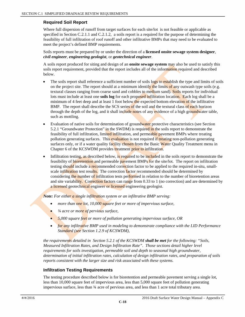
Required Soil Report Where full dispersion of runoff from target surfaces for each site/lot is not feasible or applicable as specified in Section C.2.1.1 and C.2.1.2, a soils report is a required for the purpose of determining the feasibility of full infiltration of roof runoff and other infiltrative BMPs that may need to be evaluated to meet the project’s defined BMP requirements.
Soils reports must be prepared by or under the direction of a licensed onsite sewage system designer, civil engineer, engineering geologist, or geotechnical engineer.
A soils report produced for siting and design of an onsite sewage system may also be used to satisfy this soils report requirement, provided that the report includes all of the information required and described below.
• The soils report shall reference a sufficient number of soils logs to establish the type and limits of soils on the project site. The report should at a minimum identify the limits of any outwash type soils (e.g. textural classes ranging from coarse sand and cobbles to medium sand). Soils reports for individual lots must include at least one soils log for each proposed infiltration location. Each log shall be a minimum of 4 feet deep and at least 1 foot below the expected bottom elevation of the infiltrative BMP. The report shall describe the SCS series of the soil and the textural class of each horizon through the depth of the log, and it shall include notes of any evidence of a high groundwater table, such as mottling.
• Evaluation of native soils for determination of groundwater protective characteristics (see Section 5.2.1 “Groundwater Protection” in the SWDM) is required in the soils report to demonstrate the feasibility of full infiltration, limited infiltration, and permeable pavement BMPs where treating pollution generating surfaces. This evaluation is not required if treating non-pollution generating surfaces only, or if a water quality facility chosen from the Basic Water Quality Treatment menu in Chapter 6 of the KCSWDM provides treatment prior to infiltration.
• Infiltration testing, as described below, is required to be included in the soils report to demonstrate the feasibility of bioretention and permeable pavement BMPs for the site/lot. The report on infiltration testing should include a recommended correction factor to be applied to the required in-situ, small-scale infiltration test results. The correction factor recommended should be determined by considering the number of infiltration tests performed in relation to the number of bioretention areas and site variability. Correction factors can range from 0.33 to 1 (no correction) and are determined by a licensed geotechnical engineer or licensed engineering geologist.
Note: For either a single infiltration system or an infiltrative BMP serving:
• more than one lot, 10,000 square feet or more of impervious surface,
• ¾ acre or more of pervious surface,
• 5,000 square feet or more of pollution generating impervious surface, OR
• for any infiltrative BMP used in modeling to demonstrate compliance with the LID Performance Standard (see Section 1.2.9 of KCSWDM),
the requirements detailed in Section 5.2.1 of the KCSWDM shall be met for the following: “Soils, Measured Infiltration Rates, and Design Infiltration Rate”. Those sections detail higher level requirements for soils investigation, permeable soil and depth to seasonal high groundwater, determination of initial infiltration rates, calculation of design infiltration rates, and preparation of soils reports consistent with the larger size and risk associated with these systems.
Infiltration Testing Requirements The testing procedure described below is for bioretention and permeable pavement serving a single lot, less than 10,000 square feet of impervious area, less than 5,000 square feet of pollution generating impervious surface, less than ¾ acre of pervious area, and less than 1 acre total tributary area.
#/#/2016 2016 Draft Surface Water Design Manual – Appendix C
C-18

C.1.3 APPLICATION OF FLOW CONTROL BMPS
Where required to determine feasibility/infeasibility based on native soil infiltration rates, the following test procedure is required:
Infiltration Testing Procedure 1. Excavations shall be made to the bottom elevation of the proposed infiltration facility. The measured
infiltration rate of the underlying soil shall be determined using one of the following: the EPA falling head percolation test procedure (Onsite Wastewater Treatment and Disposal Systems, EPA, 1980; see Reference Section 6-A), the double ring infiltrometer test (ASTM D3385), a single ring percolation test using a ring at least 3 feet in diameter (see Reference Section 6-A), or a larger scale Pilot Infiltration Test (PIT) as described in the 2014 Stormwater Management Manual for Western Washington and Reference 6A of this manual. The larger single ring and PIT tests have been shown to more closely match actual full-scale facility performance than smaller test methods.
2. The test hole or apparatus shall be filled with water and maintained at depths above the test elevation for the saturation periods specified for the appropriate test.
3. Following the saturation period, the rate shall be determined in accordance with the specified test procedures, with a head of 6 inches of water.
4. The design engineer shall perform sufficient tests at multiple locations in a proposed facility footprint to determine a representative infiltration rate. At least two tests shall be performed (three if using the smaller-sized EPA falling head or ASTM D3385 double ring infiltrometer test methods) for each proposed bioretention BMP location. Proposed bioretention swales require 1 test per 200 linear feet of swale with a minimum of two tests (3 if using the smaller-sized EPA falling head or ASTM D3385 double ring infiltrometer test methods) performed. Proposed permeable pavement requires 1 test per 5,000 square feet of proposed footprint with a minimum of two tests (3 if using the smaller-sized EPA falling head or ASTM D3385 double ring infiltrometer test methods) performed.
MITIGATION OF WATER QUALITY IMPACTS For projects subject to Simplified Drainage review, most water quality impacts will be adequately addressed through proper application of flow control BMPs to impervious and pervious surface as specified below. Projects in Simplified Drainage Review are required to have less than 5,000 square feet targeted pollution generating impervious surfaces and less than ¾ acres of new pollution generating pervious surfaces-- therefore, water quality facilities are not required.
C.1.3.1 SMALL LOT BMP REQUIREMENTS IF the proposed project is on a site/lot smaller than 22,000 square feet, THEN flow control BMPs must be applied as specified in the requirements below OR the project must demonstrate compliance with the LID Performance Standard (described in Section 1.2.9 of SWDM) using an approved continuous runoff model. Projects on small lots are typically single family residential improvements (e.g., homes, outbuildings, etc.) but could be a small commercial development.
1. The feasibility and applicability of full dispersion as detailed in Appendix C, Section C.2.1 must be evaluated for all target impervious surfaces. If feasible and applicable, full dispersion must be implemented as part of the proposed project. Typically, small lot full dispersion will be applicable only in subdivisions where enough forest was preserved by tract, easement, or covenant to meet the minimum requirements for full dispersion in Appendix C, Section C.2.1.1
2. Where full dispersion of target impervious roof areas is not feasible or applicable, or will cause flooding or erosion impacts, the feasibility and applicability of full infiltration as detailed in Appendix C, Section C.2.2 must be evaluated (note, this will require a soils report for the site/lot). If feasible and applicable, full infiltration of roof runoff must be implemented as part of the proposed project.
3. All target impervious surfaces not mitigated by Requirements 1 and 2 above, must be mitigated to the maximum extent feasible using one or more BMPs from the following list. Use of a given BMP is
2016 Draft Surface Water Design Manual – Appendix C #/#/2016
C-19

SECTION C.1 SIMPLIFIED DRAINAGE REVIEW REQUIREMENTS
subject to evaluation of its feasibility and applicability as detailed in Appendix C. Feasible BMPs are required to be implemented. The BMPs listed below may be located anywhere on the site/lot subject to the limitations and design specifications for each BMP. These BMPs must be implemented as part of the proposed project.
• Full Infiltration per Appendix C, Section C.2.2, or per Section 5.2, whichever is applicable
• Limited Infiltration per Appendix C, Section C.2.3,
• Bioretention per Appendix C, Section C.2.6, sized as follows:
o Inside the UGA (Rainfall region SeaTac 1.0 and less ): In till soils, provide bioretention volume based on 0.6 inches of equivalent storage depth; in outwash soils provide bioretention volume based on 0.1 inches of equivalent storage depth,
o Inside the UGA (Rainfall regions greater than SeaTac 1.0): In till soils, provide bioretention volume based on 0.8 inches of equivalent storage depth; in outwash soils, provide bioretention volume based on 0.4 inches of equivalent storage depth,
o Outside the UGA: In till soils, provide bioretention volume based on 1.9 inches of equivalent storage depth; in outwash soils provide bioretention volume based on 1.0 inches of equivalent storage depth,
• Permeable Pavement per Appendix C, Section C.2.7,
4. All target impervious surfaces not mitigated by Requirements 1,2 and 3 above, must be mitigated to the maximum extent feasible using the Basic Dispersion BMP described below. Use of Basic Dispersion is subject to evaluation of its feasibility and applicability as detailed in Appendix C. Feasible BMPs are required to be implemented. Basic Dispersion BMPs may be located anywhere on the site/lot subject to the limitations and design specifications cited in Appendix C. The BMP must be implemented as part of the proposed project.
• Basic Dispersion per Appendix C, Section C.2.4,
5. BMPs must be implemented, at minimum, for an impervious area equal to at least 10% of the site/lot for site/lot sizes up to 11,000 square feet and at least 20% of the site/lot for site/lot sizes between 11,000 and 22,000 square feet. For projects located in critical aquifer recharge areas, these impervious area amounts must be doubled. Doubling of the minimum impervious area required for BMP implementation in a CARA is not required for projects located within 200 ft. of a steep slope hazard, landslide hazard area, or erosion hazard area. If these minimum areas are not mitigated using feasible BMPs from Requirements 1, 2, 3, and 4 above, either a fee in lieu of the required minimum BMPs must be paid (requires that King County Water and Land Resources Division has established a program for determining and utilizing the fees for stormwater focused retrofit projects) OR one or more BMPs from the following list are required to be implemented to achieve compliance. These BMPs must be implemented as part of the proposed project.
• Reduced Impervious Surface Credit per Appendix C, Section C.2.9,
• Native Growth Retention Credit per Appendix C, Section C.2.10.
6. The soil moisture holding capacity of new pervious surfaces must be protected in accordance with KCC 16.82.100 (F) and (G). KCC 16.82.100(F) requires that the duff layer or native topsoil be retained to the maximum extent practicable. KCC 16.82.100(G) requires soil amendment to mitigate for lost moisture holding capacity where compaction or removal of some or all of the duff layer or underlying topsoil has occurred. The specifications for compost for soil amendment can be found in Reference 11-C.
7. Any proposed connection of roof downspouts to the local drainage system must be via a perforated pipe connection as detailed in Appendix C, Section C.2.11.
#/#/2016 2016 Draft Surface Water Design Manual – Appendix C
C-20

C.1.3 APPLICATION OF FLOW CONTROL BMPS
C.1.3.2 LARGE LOT BMP REQUIREMENTS IF the proposed project is on a site/lot that is 22,000 square feet or larger, but is not a Large Rural Lot as defined in Section 1.3.3, THEN flow control BMPs must be applied as specified in the requirements below OR the project must demonstrate compliance with the LID Performance Standard (described in Core Requirement 9, Section 1.2.9 of the SWDM) using an approved continuous runoff model.
1. The feasibility and applicability of full dispersion as detailed in Appendix C, Section C.2.1 must be evaluated for all target impervious surfaces. If feasible and applicable for any such surface, then full dispersion must be applied to that surface and implemented as part of the proposed project. Typically, full dispersion will be applicable only on the largest sites/lots where there may be enough forest area available within a threshold discharge area to meet the 15% ratio of fully dispersed impervious area to native vegetated surface.
2. Where full dispersion of target impervious roof areas is not feasible or applicable, or will cause flooding or erosion impacts, the feasibility and applicability of full infiltration of roof runoff must be evaluated in accordance with Appendix C, Section C.2.2, or Section 5.2 of the SWDM, whichever is applicable based on the type of project.11 If feasible and applicable, full infiltration of roof runoff must be implemented as part of the proposed project.
3. All target impervious surfaces not mitigated by Requirements 1 and 2 above, must be mitigated to the maximum extent feasible using one or more BMPs from the following list. Use of a given BMP is subject to evaluation of its feasibility and applicability as detailed in Appendix C. Feasible BMPs are required to be implemented. The BMPs listed below may be located anywhere on the site/lot subject to the limitations and design specifications for each BMP. These BMPs must be implemented as part of the proposed project.
Full Infiltration per Section C.2.2, or per Section 5.2, whichever is applicable
Limited Infiltration per Appendix C, Section C.2.3,
Bioretention per Appendix C, Section C.2.6, sized as follows:
o Inside the UGA (Rainfall region SeaTac 1.0 and less ): In till soils, provide bioretention volume based on 0.6 inches of equivalent storage depth; in outwash soils provide bioretention volume based on 0.1 inches of equivalent storage depth
o Inside the UGA (Rainfall regions greater than SeaTac 1.0): In till soils, provide bioretention volume based on 0.8 inches of equivalent storage depth; in outwash soils, provide bioretention volume based on 0.4 inches of equivalent storage depth,
o Outside the UGA: In till soils, provide bioretention volume based on 1.9 inches of equivalent storage depth; in outwash soils provide bioretention volume based on 1.0 inches of equivalent storage depth,
Permeable Pavement per Appendix C, Section C.2.7,
4. All target impervious surfaces not mitigated by Requirements 1,2 and 3 above, must be mitigated to the maximum extent feasible using the Basic Dispersion BMP described below. Use of Basic Dispersion is subject to evaluation of its feasibility and applicability as detailed in Appendix C. Feasible BMPs are required to be implemented. Basic Dispersion BMPs may be located anywhere on the site/lot subject the limitations and design specifications cited in Appendix C. The BMP must be implemented as part of the proposed project.
Basic Dispersion per Appendix C, Section C.2.4,
5. BMPs must be implemented, at minimum, for impervious area amounts defined as follows:
11 For projects subject to Simplified Drainage Review, and for any single family residential project subject to Full or Large Project Drainage Review, the design requirements and specifications in Appendix C, Section C.2.2 may be used for evaluation and design of full infiltration on individual lots. For all other projects, full infiltration must be evaluated and designed in accordance with the infiltration facility standards in Section 5.2.
2016 Draft Surface Water Design Manual – Appendix C #/#/2016
C-21

SECTION C.1 SIMPLIFIED DRAINAGE REVIEW REQUIREMENTS
a) For projects that will result in an impervious surface coverage on the buildable portion of the site/lot of less than 45%, flow control BMPs must be applied to 50% of target impervious surfaces.
b) For projects that will result in an impervious surface coverage of 45% to 65% on the buildable portion of the site/lot, flow control BMPs must be applied to 50% of target impervious surfaces reduced by 1.5% for each 1% of impervious surface coverage above 45% (e.g., impervious coverage of 55% results in a requirement of FCBMPs applied to 35% of target impervious surfaces).
c) For projects that will result in an impervious surface coverage greater than 65% on the buildable portion of the site/lot, flow control BMPs must be applied to 20% of the target impervious surfaces or to an impervious area equal to at least 10% of the site/lot, whichever is less.
The buildable portion of the site/lot is the total area of the site/lot minus any critical areas and minus 200 ft. buffer areas from a steep slope hazard, landslide hazard area, or erosion hazard area. If these minimum areas are not mitigated using feasible BMPs from Requirements 1, 2, 3, and 4 above, either a fee in lieu of the required minimum BMPs must be paid (requires that King County Water and Land Resources Division has established a program for determining and utilizing the fees for stormwater focused retrofit projects) OR one or more BMPs from the following list are required to be implemented to achieve compliance. These BMPs must be implemented as part of the proposed project.
Reduced Impervious Surface Credit per Appendix C, Section C.2.9,
Native Growth Retention Credit per Appendix C, Section C.2.10.
6. The soil moisture holding capacity of new pervious surfaces must be protected in accordance with KCC 16.82.100 (F) and (G). KCC 16.82.100(F) requires that the duff layer or native topsoil be retained to the maximum extent practicable. KCC 16.82.100(G) requires soil amendment to mitigate for lost moisture holding capacity where compaction or removal of some or all of the duff layer or underlying topsoil has occurred. The specifications for compost for soil amendment can be found in Reference 11-C.
7. Any proposed connection of roof downspouts to the drainage system must be via a perforated pipe connection as detailed in Appendix C, Section C.2.11.
C.1.3.3 LARGE RURAL LOT BMP REQUIREMENTS IF the proposed project is on a site/lot that is 5 acres or larger and is located outside the Urban Growth Area (UGA), THEN the project must demonstrate compliance with the LID Performance Standard (described in Section 1.2.9 of SWDM) using an approved continuous runoff model.
As an alternative to demonstrating compliance with the LID Performance Standard via modeling as described above, agricultural projects and single family residential projects (excluding subdivisions creating 10 lots or more) are given the option to apply flow control BMPs as specified in the requirements below.
1. The feasibility and applicability of full dispersion as detailed in Section C.2.1 must be evaluated for all target impervious surfaces. If feasible and applicable, full dispersion must be implemented as part of the proposed project. Typically, full dispersion will be applicable only to sites/lots or portions of sites/lots where enough forest is preserved by a clearing limit per KCC 16.82 or by recorded tract, easement, or covenant to meet the minimum requirements for full dispersion in Section C.2.1.1.
2. Where full dispersion of target impervious roof areas is not feasible or applicable, or will cause flooding or erosion impacts, the feasibility and applicability of full infiltration of roof runoff must be evaluated in accordance with Section C.2.2, or Section 5.2, whichever is applicable based on the type
#/#/2016 2016 Draft Surface Water Design Manual – Appendix C
C-22

C.1.3 APPLICATION OF FLOW CONTROL BMPS
of project.12 If feasible and applicable, full infiltration of roof runoff must be implemented as part of the proposed project.
3. All target impervious surfaces not mitigated by Requirements 1 and 2 above, must be mitigated using one or more BMPs from the following list. Use of a given BMP is subject to evaluation of its feasibility and applicability as detailed in Appendix C. The BMPs listed below may be located anywhere on the site/lot subject to the limitations and design specifications for each BMP. These BMPs must be implemented as part of the proposed project.
Full Infiltration per Section C.2.2, or per Section 5.2, whichever is applicable,
Limited Infiltration per Section C.2.3,
Bioretention per Section C.2.6, sized as follows: In till soils, provide bioretention volume based on 1.9 inches of equivalent storage depth; in outwash soils, provide bioretention volume based on 1.0 inches of equivalent storage depth,
Basic Dispersion per Section C.2.4 followed by Bioretention per Section C.2.6., with bioretention sized as follows: In till soils, provide bioretention volume based on 0.9 inches of equivalent storage depth; in outwash soils, provide bioretention volume based on 0.2 inches of equivalent storage depth,
Permeable Pavement per Section C.2.7
4. The soil moisture holding capacity of new pervious surfaces must be protected in accordance with KCC 16.82.100 (F) and (G). KCC 16.82.100(F) requires that the duff layer or native topsoil be retained to the maximum extent practicable. KCC 16.82.100(G) requires soil amendment to mitigate for lost moisture holding capacity where compaction or removal of some or all of the duff layer or underlying topsoil has occurred. The amendment must be such that the replaced topsoil is a minimum of 8 inches thick, unless the applicant demonstrates that a different thickness will provide conditions equivalent to the soil moisture holding capacity native to the site. The replaced topsoil must have an organic content of 5-10% dry weight and a pH suitable for the proposed surface vegetation (for most soils in King County, 4 inches of well-rotted compost tilled into the top 8 inches of soil is sufficient to achieve the organic content standard.) The amendment must take place between May 1 and October 1. The specifications for compost for soil amendment can be found in Reference 11-C.
5. BMPs must be applied to all new pervious surfaces according to the order of preference and extent of application specified in the following requirements:
a) The feasibility and applicability of full dispersion as detailed in Section C.2.1 (p. C-26) must be evaluated for all new pervious surface. If feasible and applicable, full dispersion must be implemented as part of the proposed project. Typically, full dispersion will be applicable only to sites/lots or portions of sites/lots where enough forest is preserved by a clearing limit per KCC 16.82 or by recorded tract, easement, or covenant to meet the minimum requirements for full dispersion in Section C.2.1.1 (p. C-26).
b) For that portion of new pervious surface not addressed in Requirement 5.a above, one or more of the following BMPs must be implemented as part of the proposed project.
• Basic Dispersion per Section C.2.4, onto native vegetated surfaces only,
• Bioretention per Appendix C, Section C.2.6, sized as follows: In till soils, provide bioretention volume based on 0.7 inches of equivalent storage depth; in outwash soils, provide bioretention volume based on 0.006 inches of equivalent storage depth.
12 For projects subject to Simplified Drainage Review, and for any single family residential project subject to Full, Directed, or Large Project Drainage Review, the design requirements and specifications in Appendix C, Section C.2.2 may be used for evaluation and design of full infiltration on individual lots. For all other projects and any project proposing a full infiltration system serving more than one lot, full infiltration must be evaluated and designed in accordance with the infiltration facility standards in Section 5.2.
2016 Draft Surface Water Design Manual – Appendix C #/#/2016
C-23

SECTION C.1 SIMPLIFIED DRAINAGE REVIEW REQUIREMENTS
• Limited Infiltration per Section C.2.3
C.1.3.4 FLOW CONTROL BMP IMPLEMENTATION REQUIREMENTS The flow control BMPs required in Section C.1.3.1, C.1.3.2, and C.1.3.3 above must be implemented in accordance with the following requirements:
1. Implementation Responsibility. All flow control BMPs required for the site/lot must be implemented (installed) by the applicant as part of the proposed project unless they have already implemented as part of a subdivision project (e.g., plat or short plat) that created the lot.
2. Maintenance Responsibility. Maintenance of all required flow control BMPs is the responsibility of the owner of the site/lot served by these BMPs. The responsibility for such maintenance must be clearly assigned to the current and future owners of the site/lot through a "declaration of covenant and grant of easement" as described in Requirement 3 below.
3. Declaration of Covenant and Grant of Easement. A declaration of covenant and grant of easement must be recorded for each site/lot that contains flow control BMPs. A draft of the proposed covenant must be reviewed and approved by DPER prior to recording. All required covenants must be recorded prior to final construction approval for the proposed project. The covenant in Reference Section C.5.2, p. C-149, (or equivalent) must be used, and is designed to achieve the following:
a) Provide notice to future owners of the presence of flow control BMPs on the lot and the responsibility of the owner to retain, uphold, and protect the flow control BMP devices, features, pathways, limits, and restrictions.
b) Include as an exhibit, a recordable version13 of the following drainage plan information:
• The flow control BMP site plan showing all developed surfaces (impervious and pervious) and the location and dimensions of flow control BMP devices, features, flowpaths (if applicable), and limits of native growth retention areas (if applicable). This plan(s) must be to scale and include site topography in accordance with the specifications for such plans in Section C.4.2 (p. C-139). Note: DPER may waive this element if, for example, the only flow control BMP proposed is a limit on impervious surface (reduced footprint).
• The flow control BMP design and maintenance details for each flow control BMP per Section C.4.3 (p. C-143). This includes a diagram (if applicable) of each flow control BMP device or feature and written maintenance and operation instructions and restrictions for each device, feature, flowpath (if applicable), native growth retention area (if applicable) and impervious surface coverage (if applicable).
c) Require that each flow control BMP be operated and maintained at the owner's expense in accordance with the above exhibit.
d) Grant King County or its successor the right to enter the property at reasonable times for purposes of inspecting the flow control BMPs and to perform any corrective maintenance, repair, restoration, or mitigation work on the flow control BMPs that has not been performed by the property owner within a reasonable time set by DNRP, and to charge the property owner for the cost of any maintenance, repair, restoration, or mitigation work performed by King County.
e) Prohibit any modification or removal of flow control BMPs without written approval from King County. In cases where the modification or removal is done under a King County development permit, the approval must be obtained from DPER (or its successor) and a covenant must be recorded to reflect the changes. In all other cases, the approval must be obtained from DNRP (or
13 Recordable version means one that meets King County's "Standard Formatting Requirements for Recording Documents" pursuant to RCW 36.18.010 and 65.04.045, available online and from the King County Recorder's Office. These requirements include specifications for such things as page size (81/2" x 14" or smaller), font size (at least 8-point), and margin width (1" on all sides of every page if there is a standard cover sheet).
#/#/2016 2016 Draft Surface Water Design Manual – Appendix C
C-24

C.1.3 APPLICATION OF FLOW CONTROL BMPS
its successor) and a covenant must be recorded to reflect the changes. Approval will be granted only if equivalent protection in terms of hydrologic performance is provided by other means.
4. Timing of Implementation. All required flow control BMPs must be installed prior to final inspection approval of constructed improvements. For BMPs that rely on vegetation, the vegetation must be planted and starting to grow prior to final construction approval.
5. Acceptance Standards. Flow control BMPs may be inspected during and/or following construction. Approval of the constructed BMPs will be based on verification that the materials and placement appear to meet the specifications and that the BMPs appear to function as designed. Onsite observations may be used to verify that materials are as specified and material receipts checked. Performance may be evaluated by a site visit while it is raining or by testing with a bucket of water or garden hose to check pavement permeability or proper connection to BMP devices/features, etc.
6. Drainage Concerns. If DPER determines that there is a potential for drainage impacts to a neighboring property or critical area, then additional measures may be required. Some flow control BMPs may not be appropriate in certain situations, and will not be allowed by DPER where they may cause drainage problems.
7. Geotechnical Concerns. A geotechnical engineer, engineering geologist, or DPER staff geologist must evaluate and approve flow control BMPs that are proposed: (A) on slopes steeper than 15%; (B) within a setback from the top of slope equal to the total vertical height of the slope area that is steeper than 15%; or (C) within 200 feet of a steep slope hazard area, erosion hazard area, or landslide hazard area. In addition, DPER may require review by a geotechnical engineer or engineering geologist of any proposed BMP that infiltrates, disperses, or directs overflow adjacent to or towards a steep slope hazard area, erosion hazard area, or landslide hazard area. DPER may also require some projects to route flows down or around such slopes using non-perforated pipes. Some flow control BMPs may not be appropriate for these locations, and will not be allowed by DPER where flows may cause erosion problems.
8. Sewage System Concerns. If DPER determines that there is a potential conflict between onsite sewage systems and flow control BMPs, additional measures may be required. Some projects may need to route flows past onsite sewage systems using non-perforated pipes. Also, some flow control BMPs may not be appropriate for these sites, and will not be allowed where sewage systems may be impacted.
9. Engineering Concerns. While most of the flow control BMPs in this appendix can be implemented by a non-engineer, there are some that have structural components that must be designed or evaluated by a civil engineer or structural engineer.14 When a BMP is proposed that has such components as identified in Section C.2, DPER may require submittal of engineering plans for that component signed and stamped by a civil engineer or structural engineer.
10. Connection to Subsurface Drains. Flow control BMPs should not be connected to subsurface drains (e.g., footing drains) as these connections may adversely affect the performance of the BMPs, and in some cases may cause reverse flow into the footing drains during storm events.
11. Simplified Drainage Plan. The type, size, and placement of proposed flow control BMPs are to be shown on the flow control BMP site plan portion of the Simplified drainage plan submitted for the proposed project. This plan must be in accordance with the specifications for such plans outlined in Section C.4 (p. C-137) unless otherwise directed by DPER.
14 Structural engineer means a person licensed by the State of Washington as a professional civil engineer specializing in structural engineering.
2016 Draft Surface Water Design Manual – Appendix C #/#/2016
C-25

SECTION C.1 SIMPLIFIED DRAINAGE REVIEW REQUIREMENTS
C.1.4 APPLICATION OF CSWPP MEASURES It is the responsibility of both the applicant and contractor to prevent the erosion and transport of sediment and other construction-related pollutants to the maximum extent practicable. Erosion and sediment control (ESC) measures and stormwater pollution prevention and spill control (SWPPS) measures must be used both during and after construction as specified in this section.
For projects subject to Simplified Drainage Review and disturbing less than 1 acre of land, the application of ESC and SWPPS measures must be in accordance with the "Simplified Site CSWPP Requirements" in Section C.1.4.1 and the "CSWPP Implementation Requirements" in Section C.1.4.2. The CSWPP Simplified Site Requirements specify the types of measures that must be considered for application to the construction site based on project-specific site features, soil conditions, weather conditions, time of year, and construction activities. The CSWPP implementation requirements are generally applicable to all projects in Simplified Drainage Review disturbing less than 1 acre.
C.1.4.1 SIMPLIFIED SITE CSWPP REQUIREMENTS For projects in Simplified Drainage Review that disturb less than 1 acre of land, all of the following Simplified site ESC and SWPPS requirements must be evaluated for applicability to the proposed project:
A. MARK CLEARING LIMITS/MINIMIZE CLEARING Prior to beginning land disturbing activities, all clearing limits, sensitive areas and their buffers, and trees that are to be preserved within the construction area and any existing or proposed LID facility areas shall be clearly marked, both in the field and on the Simplified site CSWPP plan, to prevent damage and offsite impacts. Also, clearing shall be minimized to the maximum extent practicable. See "Mark Clearing Limits/Minimize Clearing," Section C.3.5, for more detailed specifications.
B. MINIMIZE SEDIMENT TRACKED OFFSITE 1. Establish a stabilized entrance for construction vehicle access to minimize the tracking of sediment
onto public roads. Entrance and exit shall be limited to one route, if possible. See "Stabilized Construction Entrance," Section C.3.1, for detailed specifications.
2. If sediment is tracked offsite, public roads shall be cleaned thoroughly at the end of each day, or more frequently during wet weather, if necessary to prevent sediment from entering waters of the state. Sediment shall be removed from roads by shoveling or pickup sweeping and shall be transported to a controlled sediment disposal area. Street washing will be allowed only after sediment is removed in this manner. Street wash wastewater shall be controlled by pumping back onsite, or otherwise be prevented from discharging into drainage systems tributary to surface waters. This requirement shall be included as a note on the Simplified site CSWPP plan.
C. CONTROL SEDIMENT Runoff from disturbed areas must pass through a sediment control measure to prevent the transport of sediment downstream until the disturbed area is fully stabilized. Sediment controls must be installed as one of the first steps in grading and shall be functional before other land disturbing activities take place. One or more the following sediment controls may be used to meet this requirement:
• Silt Fence (See Section C.3.6)
• Vegetated Strip (See Section C.3.7)
• Triangular Silt Dike (See Section C.3.8)
• Storm Drain Inlet Protection (See Section C.3.9)
#/#/2016 2016 Draft Surface Water Design Manual – Appendix C
C-26

C.1.4 APPLICATION OF CSWPP MEASURES
D. STABILIZE EXPOSED SOILS All exposed and unworked soils shall be stabilized through the application of cover measures to protect the soil from the erosive forces of raindrop impact, flowing water, and wind erosion. One or more of the following cover measures may be used to meet this requirement during the construction phase:
• Mulching (See Section C.3.2)
• Nets and Blankets (See Section C.3.3)
• Plastic Covering (See Section C.3.4)
• Seeding (See Section C.3.10)
• Sodding (See Section C.3.11)
Cover measures shall be applied in accordance with the following requirements:
1. Cover measures must be installed if an area is to remain unworked for more than seven days during the dry season (May 1 to September 30) or for more than two consecutive working days during the wet season (October 1 to April 30). These time limits may be relaxed if an area poses a low risk of erosion due to soil type, slope gradient, anticipated weather conditions, or other factors. Conversely, the County may reduce these time limits if site conditions warrant greater protection (e.g., adjacent to significant aquatic resources or highly erosive soils) or if significant precipitation is expected.
2. Any area to remain unworked for more than 30 days shall be seeded or sodded unless the County determines that winter weather makes vegetation establishment infeasible. During the wet season, exposed ground slopes and stockpile slopes with an incline of 3 horizontal to 1 vertical (3H:1V) or steeper and with more than ten feet of vertical relief shall be covered if they are to remain unworked for more than 12 hours. Also during the wet season, the material necessary to cover all disturbed areas must be stockpiled on site. The intent of these cover requirements is to have as much area as possible covered during any period of precipitation.
E. CONTROL RUNOFF Stormwater runoff originating on the site and/or entering the site from offsite areas must be controlled so as to minimize erosion of disturbed areas and exposed cut and fill slopes, and to minimize erosive impacts on existing or proposed LID facility areas. The following runoff control measures shall be used as needed per the conditions of use and specifications for each measure:
• Interceptor Dikes and Swales (see Section C.3.12 for conditions of use and specifications)
• Ditches (see Section C.3.13 for conditions of use and specifications)
• Pipe Slope Drain (see Section C.3.14 for conditions of use and specifications)
F. CONTROL DEWATERING Accumulated water in foundation areas, excavations, and utility trenches shall be removed and disposed of in a manner that does not pollute surface waters or cause downstream erosion or flooding. See "Dewatering Control," Section C.3.15 for detailed specifications.
G. CONTROL OTHER POLLUTANTS (SWPPS) All construction activities shall be done in a manner that prevents pollution of surface waters and ground waters as specified in the Construction Stormwater Pollution Prevention Standards (detached Appendix D of the KCSWDM) and King County's Stormwater Pollution Prevention Manual (SPPM). See "Control of Other Pollutants (SWPPS) (SWPPS)," Section C.3.16, for specific measures and references to Appendix D and applicable activity sheets in the SPPM. References to applicable measures in Appendix D and activity sheets in SPPM shall be included in the Simplified site CSWPP plan.
2016 Draft Surface Water Design Manual – Appendix C #/#/2016
C-27

SECTION C.1 SIMPLIFIED DRAINAGE REVIEW REQUIREMENTS
H. PROTECT EXISTING AND PROPOSED FLOW CONTROL BMPS Protection measures shall be applied/installed and maintained so as to prevent adverse impacts to existing flow control BMPs and areas of proposed flow control BMPs for the project. Adverse impacts can prompt the requirement to restore or replace affected BMPs.
Purpose: The purpose of protecting existing and proposed flow control BMP areas is to avoid sedimentation and soil compaction that would adversely affect infiltration, and also avoid contamination by other pollutants.
When to Install: Flow control BMP area protection shall be installed or otherwise provided prior to any clearing and/or grading of the site, except that required to construct flow control BMPs.
Measures to Use: 1. Protect all flow control BMPs and proposed BMP footprints from sedimentation through installation
and maintenance of erosion and sediment control BMPs on portions of the site that drain into the flow control BMPs.
2. BMPs shall be restored to their fully functioning condition if they accumulate sediment during construction. Restoring the BMP shall include, at a minimum, removal of sediment and any sediment-laden bioretention soils, and replacing the removed soils with soils meeting the design specification. Replacement with a new fully-functioning facility may be required if restoration to the fully-functioning condition can’t be accomplished.
3. Prevent compacting Bioretention BMPs by excluding construction equipment and foot traffic. Protect completed lawn and landscaped areas from compaction due to construction equipment.
4. Control erosion and avoid introducing sediment from surrounding land uses onto permeable pavements. Do not allow muddy construction equipment on the base material or pavement. Do not allow sediment-laden runoff onto permeable pavements.
5. Pavements fouled with sediments or no longer passing an initial infiltration text must be cleaned using procedures from the local stormwater manual or the manufacturer’s procedures.
6. Keep all heavy equipment off existing soils under flow control BMPs that have been excavated to final grade to retain the infiltration rate of the soils.
I. MAINTAIN BMPS DURING CONSTRUCTION AND FINAL SITE STABILIZATION 1. TESC BMPs shall be maintained and repaired as needed throughout construction to assure continued
performance of their intended function in accordance with the BMP specifications.
2. Prior to final construction approval, the project site shall be stabilized to prevent sediment-laden water from leaving the project site after project completion. All disturbed areas of the project site shall be vegetated or otherwise permanently stabilized. At a minimum, disturbed areas must be seeded and mulched to ensure that sufficient cover will develop shortly after final approval. Mulch without seeding is adequate for small areas to be landscaped before October 1.
3. All temporary ESC and SWPPS measures shall be removed within 30 days after final site stabilization is achieved or after the temporary measures are no longer needed. Trapped sediment shall be removed or stabilized onsite. LID facilities impacted during construction shall be restored. Disturbed soil areas resulting from removal of measures or vegetation shall be permanently stabilized with seeding or sodding.
C.1.4.2 CSWPP IMPLEMENTATION AND MANAGEMENT REQUIREMENTS Projects in Simplified Drainage Review that disturb less than 1 acre of land must implement the CSWPP measures determined necessary in Section C.1.4.1 in accordance with the following requirements:
#/#/2016 2016 Draft Surface Water Design Manual – Appendix C
C-28

C.1.4 APPLICATION OF CSWPP MEASURES
1. The placement and type of proposed ESC and SWPPS measures are to be shown on the Simplified site CSWPP plan portion of the Simplified drainage plan submitted for the proposed project. This plan must be in accordance with the specifications for such plans outlined in Section C.4 (p. C-137) unless otherwise directed by DPER.
2. If DPER finds that implementation of the proposed Simplified site CSWPP plan is insufficient to prevent the discharge of sediment or other pollutants to the maximum extent practicable, additional measures will be required by DPER. In some cases, an ESC plan or a complete Construction Stormwater Pollution Plan prepared by a civil engineer per Chapter 2 of the SWDM may be required.
3. The contractor or other persons performing construction activities shall comply with the stormwater pollution prevention and spill control measures/BMPs specified for such activities in Appendix D and/or the King County Stormwater Pollution Prevention Manual. A note to this effect must be put on the approved CSWPP plan.
4. Prior to commencing construction, the applicant must identify to the County a contact person responsible for overseeing the installation and maintenance of required ESC and SWPPS measures and compliance with Appendix D and the Stormwater Pollution Prevention Manual during construction. The name and contact information for this person must be on or attached to Simplified site CSWPP plan at the time of construction.
5. Both the applicant and contractor are responsible for implementation and maintenance of the approved Simplified site CSWPP plan and any additional measures required by the County.
6. The Simplified site CSWPP plan shall be retained onsite or within reasonable access to the site. The plan shall be modified whenever there is a significant change in the design, construction, operation, or maintenance at the construction site that has, or could have, a significant effect on the discharge of pollutants to surface waters. The plan shall be modified, if during inspections or investigations conducted by the County, it is determined that the plan is ineffective in eliminating or significantly minimizing pollutants in stormwater discharges from the site. The plan shall be modified as necessary to include additional or modified measures designed to correct problems identified.
2016 Draft Surface Water Design Manual – Appendix C #/#/2016
C-29

SECTION C.1 SIMPLIFIED DRAINAGE REVIEW REQUIREMENTS
C.1.5 SIMPLIFIED SUBMITTAL REQUIREMENTS For projects in Simplified Drainage Review, the items listed below must be submitted to DPER for review unless the item is not applicable or necessary as specified for that item below or as determined by DPER. See Section C.5.1 (p. C-147) for a description of the DPER permit review process for Simplified Drainage Review.
1. A Simplified drainage plan, which includes the components specified in Section C.4 (p. C-137) unless otherwise directed by DPER. These components vary depending on whether the project is an individual lot development or a subdivision. For most projects in Simplified Drainage Review (i.e., individual lot projects), the required components of a Simplified drainage plan include a flow control BMP site plan, flow control BMP design and maintenance details, a Simplified site CSWPP plan, and a written drainage assessment with supporting documentation (e.g., soils report, special studies, etc.). Note: subdivisions in Simplified Drainage Review that do not require engineering plans or analysis will typically be asked to complete Simplified project drainage plans prior to preliminary approval of the subdivision. Projects submitting Simplified drainage plans after preliminary approval must include in the written assessment a discussion of any changes made to the project after preliminary approval.
2. A draft of the declaration of covenant and grant of easement required to be recorded for application of flow control BMPs on an individual site/lot in accordance with Requirement 3 of Section C.1.3.4.
3. A copy of any recorded covenant that limits the amount of impervious surface or clearing on the site for purposes of qualifying for Simplified Drainage Review. If one does not exist or does not include provisions for County inspection, it must be combined with the covenant required for application of flow control BMPs.
4. An engineering plan and technical information report signed and stamped by a civil engineer if needed to address targeted drainage review requirements identified in Section C.1.1 and described in Section C.1.2. The specifications for such plans and reports are found in Chapter 2 of the SWDM.
#/#/2016 2016 Draft Surface Water Design Manual – Appendix C
C-30

KING COUNTY, WASHINGTON, SURFACE WATER DESIGN MANUAL, APPENDIX C
C.2 FLOW CONTROL BMPs This section presents the minimum design requirements, specifications, and infeasibility criteria for each type of flow control BMP. Flow control BMPs are methods and designs for dispersing, infiltrating, or otherwise reducing or preventing development-related increases in runoff at or near the sources of those increases. Flow control BMPs include, but are not limited to, preservation and use of native vegetated surface to fully disperse runoff; use of other pervious surfaces to disperse runoff; roof downspout infiltration; permeable pavements; rainwater harvesting; bioretention; and reduction of development footprint.
Intent of Flow Control BMPs The primary intent of flow control BMPs is to mitigate the hydrologic impacts of impervious surface, which means preventing or reducing the increased runoff peaks, volumes, and loss of groundwater recharge associated with conversion of forest or grassland to impervious surface. Such impacts are known to cause or contribute to downstream flooding, erosion, sedimentation, loss of aquatic habitat, and loss of groundwater available for human consumption and summer stream flows necessary for fish use.
The secondary intent of flow control BMPs is to mitigate the water quality impacts of impervious surface and in some cases, new pervious surface, where the new pervious surface exceeds 3/4 acre.
Some flow control BMPs are more effective than others at minimizing hydrologic impacts and are given preference in the BMP application requirements. For example, where substantial amounts of native vegetation are being retained onsite, "full dispersion" of runoff is the preferred or required BMP if it can be implemented onsite per the minimum design requirements and specifications in Section C.2.1 (p. C-32).
Organization of Section C.2 Section C.2 is organized as follows:
• Section C.2.1, "Full Dispersion" (p. C-32)
• Section C.2.2, "Full Infiltration" (p. C-48)
• Section C.2.3, "Limited Infiltration" (p. C-57)
• Section C.2.4, "Basic Dispersion" (p. C-60)
• Section C.2.5, “Farmland Dispersion” (p. C-69)
• Section C.2.6, "Bioretention" (p. C-71)
• Section C.2.7, "Permeable Pavement" (p. C-84)
• Section C.2.8, "Rainwater Harvesting" (p. C-92)
• Section C.2.9, "Reduced Impervious Surface Credit" (p. C-95)
• Section C.2.10, "Native Growth Retention Credit" (p. C-100)
• Section C.2.11, "Perforated Pipe Connection" (p. C-102)
Other Resources Other resources are available that may be helpful in the design of flow control BMPs. The state Department of Ecology Stormwater Management Manual for Western Washington (2014) and the Puget Sound Water Quality Action Team's Low Impact Development Technical Guidance Manual for Puget Sound (January 2005) are both good references and sources of ideas. For many of the above BMPs, these manuals may provide much more design information than is presented in this appendix. Where such information conflicts with the minimum design requirements and specifications contained herein, King County's standards shall govern.
2016 Draft Surface Water Design Manual – Appendix C #/#/2016
C-31

SECTION C.2 FLOW CONTROL BMPs
C.2.1 FULL DISPERSION Full dispersion is a BMP strategy for minimizing the area of onsite developed surface (i.e., impervious or non-native pervious surface) relative to native vegetated surface (e.g., forested surface) together with the application of dispersion techniques that utilize the natural capacity of the native vegetated surface to mitigate the runoff quantity and quality impacts of the developed surfaces. Developed surfaces that meet the minimum requirements and specifications for full dispersion as set forth in this section are referred to as fully dispersed surfaces. As specified in the SWDM, fully dispersed impervious surface is not subject to the "flow control facility requirement." Similarly, any pollution-generating impervious surface or pervious surface that is fully dispersed is not subject to the water quality facility requirements of the SWDM.
Applicable Surfaces Full dispersion may be applied to any impervious surface such as a roof, driveway, parking area, or road, and to any non-native pervious surface such as a lawn, landscaped area, or pasture.
Infeasibility Criteria Full dispersion is considered infeasible and not required for projects that cannot meet the minimum design requirements listed below. Where geotechnical evaluation and approval is required for full dispersion that proposes to discharge towards or is within described setbacks of a steep slope hazard area, erosion hazard area, landslide hazard area, or slopes greater than 15%, full dispersion is considered infeasible and not required. Though not required in these circumstances, a project proponent may still opt to use full dispersion as long as the geotechnical evaluation and approval requirement is met.
Operation and Maintenance See Section C.2.1.9 (p. C-46).
C.2.1.1 MINIMUM DESIGN REQUIREMENTS FOR FULL DISPERSION All of the following requirements must be met in order for full dispersion to be feasible and applicable to a target impervious surface or new pervious surface:
1. The total area of impervious surface being fully dispersed must be no more than 15% of the total area of native vegetated surface being preserved by a clearing limit per KCC 16.82 or by a recorded tract, easement, or covenant on the site. This area of native vegetated surface must be delineated on the site as specified in and subject to the restrictions in Section C.2.1.2. The total area of impervious surface plus non-native pervious surface15 being fully dispersed must be no more than 35% of the site. Note: for sites that span the divide between two or more stream basins, DPER may require that these percentages be applied by "threshold discharge area" as defined in the Surface Water Design Manual.
2. The runoff from a fully dispersed surface must be discharged using one of the following dispersion devices in accordance with the design specifications and maximum area of fully dispersed surface for each device as set forth in Sections C.2.1.3 through C.2.1.6:
• Splash blocks (see Section C.2.1.3, p. C-34)
• Rock pads (see Section C.2.1.4, p. C-35)
• Gravel filled trenches (see Section C.2.1.5, p. C-35)
• Sheet flow (see Section C.2.1.6, p. C-37)
15 Non-native pervious surface means a pervious surface that does not meet the definition of a native vegetated surface and is not a natural water body or critical area.
#/#/2016 2016 Draft Surface Water Design Manual – Appendix C
C-32

C.2.1 FULL DISPERSION
3. A native vegetated flowpath segment of at least 100 feet in length (25 feet for sheet flow from a non-native pervious surface) must be available along the flowpath that runoff would follow upon discharge from a dispersion device listed in Minimum Requirement 2 above (note that the 100-foot minimum flowpath length may be reduced on projects located outside of the Urban Growth Area and where sheet flow is used with a native vegetated flowpath segment over outwash soils as specified in Section C.2.1.6). The native vegetated flowpath segment must meet all of the following criteria:
a) The flowpath segment must be over native vegetated surface.
b) The flowpath segment must be onsite or in an offsite tract or easement area reserved for such dispersion.
c) The slope of the flowpath segment must be no steeper than 15% for any 20-foot reach of the flowpath segment.
d) The flowpath segment must be located between the dispersion device and any downstream drainage feature such as a pipe, ditch, stream, river, pond, lake, or wetland. All or a portion of the flowpath segment may be located within a critical area buffer.
e) The flowpath segments for adjacent dispersion devices must be sufficiently spaced in order to prevent overlap of flows in the segment areas. The minimum spacing between flowpath segments is specified for each dispersion device in subsequent sections, and includes an exception made in cases where sheet flow from a non-native pervious surface overlaps with other flowpath segments.
4. For sites with septic systems, the discharge of runoff from dispersion devices must be located down slope of the primary and reserve drainfield areas. DPER permit review staff can waive this requirement if site topography clearly prohibits discharged flows from intersecting the drainfield.
5. Dispersion devices are not allowed in critical area buffers (unless approved by DPER) or on slopes steeper than 20%.
6. Dispersion devices are not allowed within 50 feet of a steep slope hazard area, erosion hazard area, or landslide hazard area.
7. Dispersion devices proposed on slopes steeper than 15% must be approved by a geotechnical engineer or engineering geologist unless otherwise approved by the DPER staff geologist. The geotechnical analysis must consider cumulative impacts from the project and surrounding areas under full built- out conditions.
8. Dispersion devices proposed near slopes steeper than 15% must be approved by a geotechnical engineer or engineering geologist unless otherwise approved by the DPER staff geologist if the facility is located within a setback from the top of slope equal to the total vertical height of the slope area that is steeper than 15%. The geotechnical analysis must consider cumulative impacts from the project and surrounding areas under full built- out conditions.
9. Dispersion devices that direct runoff toward a slope steeper than 15% may require evaluation and approval of the proposal by a geotechnical engineer or engineering geologist as determined by DPER. The geotechnical analysis must consider cumulative impacts from the project and surrounding areas under full built- out conditions.
10. Dispersion devices proposed within 200 feet of a steep slope hazard area, erosion hazard area, or landslide hazard area must be approved by a geotechnical engineer or engineering geologist unless otherwise approved by the DPER staff geologist. The geotechnical analysis must consider cumulative impacts from the project and surrounding areas under full built- out conditions.
11. The dispersion of runoff must not create flooding or erosion impacts as determined by the DPER. If runoff is discharged toward a landslide hazard area, erosion hazard area, or steep slope hazard area, DPER may require evaluation and approval of the proposal by a geotechnical engineer or engineering geologist. The geotechnical analysis must consider cumulative impacts from the project and surrounding areas under full built- out conditions.
2016 Draft Surface Water Design Manual – Appendix C #/#/2016
C-33

SECTION C.2 FLOW CONTROL BMPs C.2.1.2 DELINEATION OF NATIVE VEGETATED AREA FOR FULL DISPERSION
The area of native vegetated surface used for full dispersion must be delineated as a "native growth retention area" on the flow control BMP site plan that will be attached to the required declaration of covenant and grant of easement per Requirement 3 of Section C.1.3.4. Delineation of the native growth retention area is subject to the following restrictions:
1. The principle restriction on native growth retention areas is removal of vegetation and trees. All trees within the native growth retention area at the time of permit application shall be retained, aside from approved timber harvest activities and the removal of dangerous and diseased trees.
2. The native growth retention area may include any unsubmerged16 critical areas and any critical area buffers.
3. The native growth retention area may include previously cleared areas replanted by the proposed project in accordance with the native vegetated landscape specifications in Section C.2.1.8 (p. C-44).
4. The native growth retention area may be used for passive recreation and related facilities, including pedestrian and bicycle trails, nature viewing areas, fishing and camping areas, and other similar activities that do not require permanent structures, provided that cleared areas and areas of compacted soil associated with these areas and facilities do not exceed eight percent of the native growth retention area.
5. The native growth retention area may contain utilities and utility easements, including other flow control BMPs, but not septic systems.
Note: the Public Benefit Rating System (PBRS) provides tax credit for properties that preserve 4 acres or more of contiguous open space in rural areas. Additional credits are granted under the forested open space category, provided a Forest Management Plan is developed that maintains the open space in a fully forested condition.
C.2.1.3 USE OF SPLASH BLOCKS FOR FULL DISPERSION Splash blocks such as that shown in Figure C.2.1.A (p. C-39) may be used to disperse the runoff collected from small amounts of roof area and discharged via a downspout.
Design Specifications 1. No more than 700 square feet of roof area may be drained to a single splash block unless the native
vegetated flowpath segment is longer than the 100-foot minimum length specified in Minimum Requirement 3 of Section C.2.1.1.
2. A maximum roof area of 1,400 square feet may be discharged to a single splash block if the native vegetated flowpath segment is at least 200 feet in length. Note: for roof areas larger than 700 square feet, the splash block should be located away from building or other provisions should be made to prevent flooding/erosion problems.
3. For roof areas of between 700 square feet and 1,400 square feet, the length of the flowpath segment may vary proportionally between 100 and 200 feet.
4. For purposes of maintaining adequate separation of flows discharged from adjacent dispersion devices, the native vegetated flowpath segment for the splash block must have at least 50 feet of separation from an adjacent flowpath segment at the downstream end of whichever segment is the shorter. Exception: where sheet flow from a non-native pervious surface overlaps with the flowpath of a splash block, the splash block flowpath segment must be extended at least 1 foot for every 3 feet of non-native pervious surface area width draining to the same flowpath. Note that width is measured in the general direction that runoff flows across the non-native pervious surface.
16 Unsubmerged means outside the ordinary high water mark of streams, lakes, and wetlands. #/#/2016 2016 Draft Surface Water Design Manual – Appendix C
C-34

C.2.1 FULL DISPERSION
C.2.1.4 USE OF ROCK PADS FOR FULL DISPERSION Pads of crushed rock, 2 feet wide (perpendicular to flow) by 3 feet long by 6 inches deep, may be used as a dispersion device to discharge small amounts of concentrated runoff from impervious surface or non-native pervious surface.
Design Specifications 1. No more than 700 square feet of impervious surface may be drained to a single rock pad unless the
native vegetated flowpath segment is longer than the 100-foot minimum length specified in Minimum Requirement 3 of Section C.2.1.1 above. If the developed surface is non-native pervious surface other than pasture, no more than 2,500 square feet may be drained to a single rock pad with a 100-foot native vegetated flowpath segment. For pasture, the maximum is 8,000 square feet. Combinations of different surfaces draining to a single rock pad are allowed provided that the sum of each surface area divided by its maximum (e.g., impervious area divided by 700) is less than or equal to 1.0.
2. A maximum impervious surface area of 1,400 square feet may be drained to a single rock pad if the native vegetated flowpath segment is at least 200 feet in length. For non-native pervious surface other than pasture, the maximum area is 5,000 square feet. For pasture, the maximum is 16,000 square feet. Again, combinations of different surfaces are allowed as explained in Item 1 above.
3. For impervious surface areas of between 700 and 1,400 square feet, the length of the flowpath segment may vary proportionally between 100 and 200 feet. This variation is also allowed for non-native pervious surfaces (i.e., between 2,500 and 5,000 square feet for surfaces other than pasture, and between 8,000 and 16,000 square feet for pasture).
4. For purposes of maintaining adequate separation of flows discharged from adjacent dispersion devices, the native vegetated flowpath segment for the rock pad must have at least 50 feet of separation from an adjacent flowpath segment at the downstream end of whichever segment is the shorter. Exception: where sheet flow from a non-native pervious surface overlaps with the flowpath of a rock pad, the rock pad flowpath segment must be extended at least 1 foot for every 3 feet of non-native pervious surface area width draining to the same flowpath. Note that width is measured in the general direction that runoff flows across the non-native pervious surface.
C.2.1.5 USE OF GRAVEL FILLED TRENCHES FOR FULL DISPERSION Either of the two types of gravel filled trenches (also called "dispersion trenches") shown in Figure C.2.1.C (p. C-41) and Figure C.2.1.D (p. C-42) may be used as a dispersion device to spread the discharge of concentrated runoff from any type of developed surface.
General Design Specifications 1. All trenches are filled with 3/4-inch to 11/2-inch washed rock.
2. In outwash soils, a treatment liner to protect groundwater quality per Section 6.2.4 should be provided underneath the trench.
3. All trenches must be placed at least 10 feet from any building and must be as parallel as possible to the contour of the ground.
4. For purposes of maintaining adequate separation of flows discharged from adjacent dispersion devices, the outer edge of the native vegetated flowpath segment for the dispersion trench must have at least 50 feet of separation from an adjacent flowpath segment at the downstream end of whichever segment is the shorter. Exception: where sheet flow from a non-native pervious surface overlaps with the flowpath of a dispersion trench, the dispersion trench flowpath segment must be extended at least 1 foot for every 3 feet of non-native pervious surface area width draining to the same flowpath. Note that width is measured in the general direction that runoff flows across the non-native pervious surface.
2016 Draft Surface Water Design Manual – Appendix C #/#/2016
C-35

SECTION C.2 FLOW CONTROL BMPs
Design Specifications for Simple 10-Foot Trench (Full Dispersion) 1. The simple 10-foot-long trench illustrated in Figure C.2.1.B (p. C-40) and Figure C.2.1.C (p. C-41)
must be at least 2-feet-wide by 18-inches deep.
2. The 10-foot trench length is the maximum allowed without a notch grade board as shown in Figure C.2.1.D (p. C-42).
3. No more than 1,400 square feet of impervious area may be drained to a single 10-foot trench unless the native vegetated flowpath segment is longer than the 100-foot minimum length specified in Minimum Requirement 3 of Section C.2.1.1 above. If the developed surface is non-native pervious surface other than pasture, no more than 5,000 square feet may be drained to a single 10-foot trench with a 100-foot native vegetated flowpath segment. For pasture, the maximum is 16,000 square feet. Combinations of different surfaces draining to a single 10-foot trench are allowed provided that the sum of each surface area divided by its maximum (e.g., impervious area divided by 1,400) is less than or equal to 1.0.
4. A maximum impervious surface area of 2,800 square feet may be drained to a single 10-foot trench if the native vegetated flowpath segment is at least 200 feet in length. For non-native pervious surface other than pasture, the maximum area is 10,000 square feet. For pasture, the maximum is 32,000 square feet. Again, combinations of different surfaces are allowed as explained in Item 3 above.
5. For impervious surface areas of between 1,400 and 2,800 square feet, the length of the flowpath segment may vary proportionally between 100 and 200 feet. This variation is also allowed for non-native pervious surfaces (i.e., between 5,000 and 10,000 square feet for surfaces other than pasture, and between 16,000 and 32,000 square feet for pasture).
Design Specifications for 50-Foot Trench with Notch Board (Full Dispersion) 1. The 50-foot-long trench with notch grade board detailed in Figure C.2.1.D (p. C-42) must be at least
2-feet wide by 24-inches deep.
2. The 50-foot trench length is the longest allowed.
3. No more than 5,000 square feet of impervious area may be drained to a single 50-foot trench unless the native vegetated flowpath segment is longer than the 100-foot minimum length specified in Minimum Requirement 3 of Section C.2.1.1 above. If the developed surface is non-native pervious surface other than pasture, no more than 17,500 square feet may be drained to a single 50-foot trench with a 100-foot native vegetated flowpath segment. For pasture, the maximum is 1.25 acres (54,450 square feet). Combinations of different surfaces draining to a single 50-foot trench are allowed provided that the sum of each surface area divided by its maximum (e.g., impervious area divided by 5,000) is less than or equal to 1.0.
4. A maximum impervious surface area of 10,000 square feet may be drained to a single 50-foot trench if the native vegetated flowpath segment is at least 200 feet in length. For non-native pervious surface other than pasture, the maximum area is 35,000 square feet. For pasture, the maximum is 2.5 acres (108,900 square feet). Again, combinations of different surfaces are allowed as explained in Item 3 above.
5. For between 5,000 square feet and 10,000 square feet of impervious area, the length of the flowpath segment may vary proportionally between 100 and 200 feet for a 50-foot trench. The trench length may also vary proportionally between the 10-foot trench values above and the 50-foot values given here. For impervious surface areas of between 5,000 and 10,000 square feet, the length of the flowpath segment may vary proportionally between 100 and 200 feet. This variation is also allowed for non-native pervious surfaces (i.e., between 17,500 and 35,000 square feet for surfaces other than pasture, and between 1.25 and 2.5 acres for pasture).
6. Manifolds may be used to split flows between up to four 50-foot trenches.
#/#/2016 2016 Draft Surface Water Design Manual – Appendix C
C-36

C.2.1 FULL DISPERSION
C.2.1.6 USE OF SHEET FLOW FOR FULL DISPERSION Sheet flow, as a dispersion device, is the grading of a developed surface (either a strip of impervious surface or a patch of non-native pervious surface) as needed to avoid the concentration of runoff before and after discharge from the surface. Two types of sheet flow, one for impervious surface and one for pervious surface, are detailed below.
Design Specifications for Impervious Surface Sheet Flow (Full Dispersion) 1. The strip of impervious surface may be either roof (with no gutter) or pavement. The edge of the
impervious strip and the ground adjacent to or immediately below the edge must be level or sloped no more than 5% along the edge as shown in Figure C.2.1.E (p. C-43).
2. A 2-foot-wide, 4-to-6 inch-deep, strip of crushed rock or the extended base course of a road or driveway must be provided at or below the edge of the impervious strip to facilitate dispersal of runoff. In outwash soils, a treatment liner to protect groundwater quality per Section 6.2.4 should be provided underneath this flow spreader.
3. No more than a 25-foot-wide strip of impervious surface may be sheet flowed in this manner unless the native vegetated flowpath segment is longer than the 100-foot minimum length specified in Minimum Requirement 3 of Section C.2.1.1 above.
4. A maximum 50-foot-wide strip may be sheet flowed if the flowpath segment is at least 200 feet in length.
5. For strip widths of between 25 and 50 feet, the length of the flowpath segment may vary proportionally between 100 and 200 feet in length.
6. For projects located outside of the Urban Growth Area, the length of the flowpath segment may be reduced to 10 feet for each 20 feet of strip width up to maximum of strip width of 40 feet, provided the following criteria are met:
a) The native vegetated flowpath segment is over outwash soils that have a measured infiltration rate of 4 inches per hour or greater for all the soil within a three foot depth, and
b) The depth to the maximum groundwater elevation is at least 3 feet
7. For purposes of maintaining adequate separation of flows discharged from adjacent dispersion devices, the outer edge of the native vegetated flowpath segment for the strip of impervious surface must have at least 50 feet of separation from an adjacent flowpath segment at the downstream end of whichever segment is the shorter. Exception: where sheet flow from a non-native pervious surface overlaps with the flowpath for sheet flow from an impervious surface, the impervious surface flowpath segment must be extended at least 1 foot for every 3 feet of non-native pervious surface area width draining to the same flowpath. Note that width is measured in the general direction that runoff flows across the non-native pervious surface.
Design Specifications for Pervious Surface Sheet Flow (Full Dispersion) 1. The area of non-native pervious surface being dispersed by sheet flow must have a width17 of no more
than 25 feet unless the native vegetated flowpath segment is longer than the 25-foot minimum length specified in Minimum Requirement 3 of Section C.2.1.1 above.
2. If the width of the non-native pervious surface is greater than 25 feet, the vegetated flowpath segment must be extended 1 foot for every 3 feet of width beyond 25 feet up to a maximum width of 250 feet.
3. The topography of the non-native pervious surface must be such that runoff will not concentrate prior to discharge from surface.
17 Width is measured in the general direction that runoff flows across the area of non-native pervious surface. For irregular-shaped areas, the width may be an average of distances along multiple paths of runoff across the non-native pervious surface.
2016 Draft Surface Water Design Manual – Appendix C #/#/2016
C-37

SECTION C.2 FLOW CONTROL BMPs
4. The vegetated flowpath segment for sheet flow from non-native pervious surface may overlap with the flowpath segments for other dispersion devices provided adjustments are made to the length of those segments as specified in the design specifications for each dispersion device.
C.2.1.7 FULL DISPERSION FIGURES AND SUMMARY INFORMATION This section contains the figures referenced in the preceding sections for details on full dispersion devices and includes a useful summary table of the flowpath lengths and capacities of the dispersion devices.
TABLE C.2.1.A SUMMARY OF DISPERSION DEVICE FLOWPATH LENGTHS & CAPACITIES
Full Dispersion Device
Native Vegetated Flowpath Length
Maximum Impervious Surface Amount
Maximum Non-Native Pervious Surface Amount
Non-Pasture Pasture Splash Block 100 feet 700 sq ft NA NA
200 feet 1,400 sq ft NA NA
Rock Pad 100 feet 700 sq ft 2,500 sq ft 8,000 sq ft
200 feet 1,400 sq ft 5,000 sq ft 16,000 sq ft
10-foot Gravel Trench
100 feet 1,400 sq ft 5,000 sq ft 16,000 sq ft
200 feet 2,800 sq ft 10,000 sq ft 32,000 sq ft
50-foot Gravel Trench
100 feet 5,000 sq ft 17,500 sq ft 54,450 sq ft
200 feet 10,000 sq ft 35,000 sq ft 108,900 sq ft
Sheet Flow from Impervious Surface
100 feet* 25-ft strip width NA NA
200 feet* 50-ft strip width NA NA
Sheet Flow from Non-Native Pervious Surface
25 feet NA 25 feet of width in direction of flow
50 feet NA 100 feet of width in direction of flow
75 feet NA 175 feet of width in direction of flow
100 feet NA 250 feet of width in direction of flow
* Reducible to 10 feet for each 20 feet of strip width when dispersing over outwash soils outside the UGA.
#/#/2016 2016 Draft Surface Water Design Manual – Appendix C
C-38

C.2.1 FULL DISPERSION
FIGURE C.2.1.A TYPICAL SPLASH BLOCK
2016 Draft Surface Water Design Manual – Appendix C #/#/2016
C-39

SECTION C.2 FLOW CONTROL BMPs
FIGURE C.2.1.B DRIVEWAY APPLICATION OF DISPERSION TRENCH AND ROCK PAD
10-foot long dispersion trench
Min 100-foot-long Native Vegetated Flowpath
Segment (NVFS)
≤1,400 sq ft for a 100-ft NVFS ≤2,800 sq ft for a 200-ft NVFS
≤700 sq ft for a 100-ft NVFS ≤1,400 sq ft for a 200-ft NVFS
Slot drain Diagonal asphalt berm – 2 to 4 inches high
PLAN VIEW OF DRIVEWAY NTS
2-ft x 3-ft x 6-inch crushed rock pad
50-foot separation between flowpath segments
Min 100-foot-long Native Vegetated Flowpath Segment
Edge of undisturbed native vegetation
#/#/2016 2016 Draft Surface Water Design Manual – Appendix C
C-40
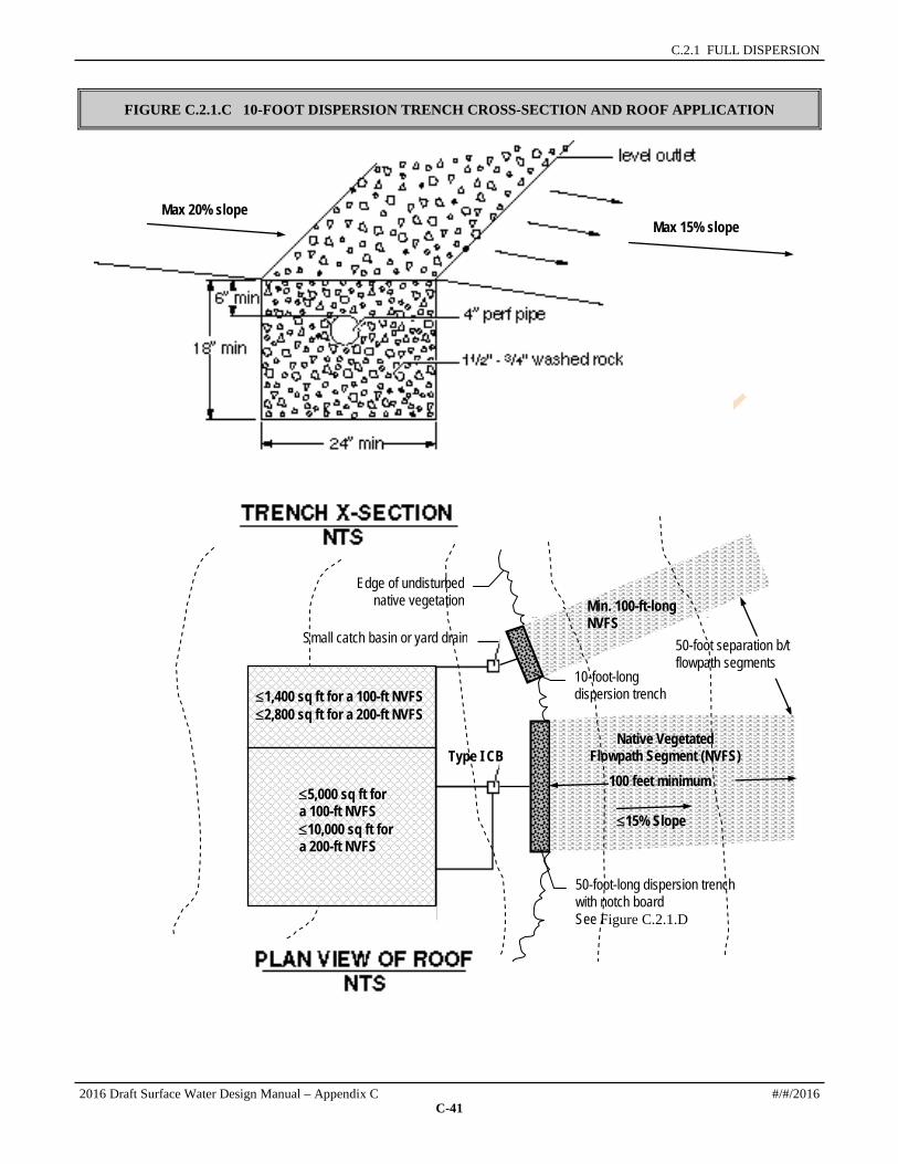
C.2.1 FULL DISPERSION
FIGURE C.2.1.C 10-FOOT DISPERSION TRENCH CROSS-SECTION AND ROOF APPLICATION
Max 15% slope Max 20% slope
Small catch basin or yard drain
50-foot-long dispersion trench with notch board See Figure C.2.1.D
Type I CB
10-foot-long dispersion trench
Native Vegetated Flowpath Segment (NVFS)
Edge of undisturbed native vegetation
50-foot separation b/t flowpath segments
Min. 100-ft-long NVFS
≤1,400 sq ft for a 100-ft NVFS ≤2,800 sq ft for a 200-ft NVFS
100 feet minimum ≤5,000 sq ft for a 100-ft NVFS ≤10,000 sq ft for a 200-ft NVFS
≤15% Slope
2016 Draft Surface Water Design Manual – Appendix C #/#/2016
C-41

SECTION C.2 FLOW CONTROL BMPs
FIGURE C.2.1.D 50-FOOT DISPERSION TRENCH WITH NOTCHED BOARD
#/#/2016 2016 Draft Surface Water Design Manual – Appendix C
C-42

C.2.1 FULL DISPERSION
FIGURE C.2.1.E APPLICATION OF SHEET FLOW DISPERSION
PLAN VIEW NTS
100 feet minimum
Native Vegetated Flowpath Segment
(NVFS) Width ≤25 ft for a 100-ft NVFS
Width ≤50 ft for a 200-ft NVFS
Crushed rock strip 2-ft wide
≤5% Slope
Edge of undisturbed native vegetation
≤15% Slope
2016 Draft Surface Water Design Manual – Appendix C #/#/2016
C-43

SECTION C.2 FLOW CONTROL BMPs
C.2.1.8 NATIVE VEGETATED LANDSCAPE SPECIFICATIONS Native vegetated landscape is basically the manmade version of a native vegetated surface. It may be used in situations where an applicant wishes to convert a previously developed surface to a native vegetated surface for purposes of meeting full dispersion requirements or code requirements for forest retention. Native vegetated landscape is intended to have the soil, vegetation, and runoff characteristics approaching that of natural forestland.
Conversion of a developed surface to native vegetated landscape requires the removal of impervious surface, de-compaction of soils, and the planting of native trees, shrubs, and ground cover in compost-amended soil according to all of the following specifications:
1. Existing impervious surface and any underlying base course (e.g., crushed rock, gravel, etc.) must be completely removed from the conversion area(s).
2. Underlying soils must be broken up to a depth of 18 inches. This can be accomplished by excavation or ripping with either a backhoe equipped with a bucket with teeth, or a ripper towed behind a tractor.
3. At least 4 inches of well-decomposed compost must be tilled into the broken up soil as deeply as possible. The finished surface should be gently undulating and must be only lightly compacted.
4. The area of native vegetated landscape must be planted with native species trees, shrubs, and ground cover from Table C.2.1.B (p. C-45). Species must be selected as appropriate for site shade and moisture conditions, and in accordance with the following requirements:
a) Trees: a minimum of two species of trees must be planted, one of which is a conifer. Conifer and other tree species must cover the entire landscape area at the spacing given in Table 1.
b) Shrubs: a minimum of two species of shrubs should be planted. Space plants to cover the entire landscape area, excluding points where trees are planted.
c) Groundcover: a minimum of two species of ground cover should be planted. Space plants so as to cover the entire landscape area, excluding points where trees or shrubs are planted.
Note: for landscape areas larger than 10,000 square feet, planting a greater variety of species than the minimum suggested above is strongly encouraged. For example, an acre could easily accommodate three tree species, three species of shrubs, and two or three species of groundcover.
5. At least 4 inches of hog fuel or other suitable mulch must be placed between plants as mulch for weed control. It is also possible to mulch the entire area before planting; however, an 18-inch diameter circle must be cleared for each plant when it is planted in the underlying amended soil. Note: plants and their root systems that come in contact with hog fuel or raw bark have a poor chance of survival.
6. Plantings must be watered consistently once per week during the dry season for the first two years.
7. The plantings must be well established on at least 90% of the converted area in order to be considered a native vegetated surface. A minimum of 90% plant survival is required after 3 years.
Conversion of an area that was under cultivation to native vegetated landscape requires a different treatment. Elimination of cultivated plants, grasses and weeds is required before planting and will be required on an on-going basis until native plants are well-established. The soil should be tilled to a depth of 18 inches. A minimum of 8 inches of soil having an organic content of 6 to 12 percent is required, or a four inch layer of compost may be placed on the surface before planting, or 4 inches of clean wood chips may be tilled into the soil, as recommended by a landscape architect or forester. After soil preparation is complete, continue with steps 4 through 7 above. Placing 4 inches of compost on the surface may be substituted for the hog fuel or mulch. For large areas where frequent watering is not practical, bare-root stock may be substituted at a variable spacing from 10 to 12 feet o.c. (with an average of 360 trees per acre) to allow for natural groupings and 4 to 6 feet o.c. for shrubs. Allowable bare-root stock types are 1-1, 2-1, P-1 and P-2. Live stakes at 4 feet o.c. may be substituted for willow and red-osier dogwood in wet areas.
#/#/2016 2016 Draft Surface Water Design Manual – Appendix C
C-44

C.2.1 FULL DISPERSION
TABLE C.2.1.B SELECTED NATIVE VEGETATION, SIZE, AND SPACING REQUIREMENTS
Species Type Sun and Moisture Preferences Planted Size
Spacing
TREES Douglas fir (Psedotsuga menziesii) conifer Sun, dry to moist soil 5 gallon,
6'-7' B&B 12' o.c.
Western red cedar (Thuja plicata) conifer Sun or shade, moist to wet soil 5 gallon, 6'-7' B&B
12' o.c.
Western hemlock (Tsuga heterophylla) conifer Sun or shade, well-drained soil 5 gallon, 6'-7' B&B
12' o.c.
Sitka spruce (Picea sitchensis) conifer Sun or shade, moist mineral soils to wet soils
5 gallon, 6'-7' B&B
12' o.c.
Shore Pine (Pinus contorta var. contorta)
Conifer Sun to partial shade, dry to wet 5 gallon, 6'-7' B&B
12' o.c.
Western white pine (Pinus monticola) Conifer Sun to part shade, dry to moist 5 gallon, 6'-7' B&B
12' o.c.
Grand fir (Abies grandis) Conifer Sun to shade, dry to moist 5 gallon, 6'-7' B&B
12' o.c.
Red alder (Alnus rubra) tree Sun, a Nitrogen fixer, 5 gallon, 5'-6' B&B
12' o.c.
Bigleaf maple (Acer macrophyllum) tree Sun or shade, dry to moist soil 5 gallon, 5'-6' B&B
12' o.c.
Black cottonwood (Populus trichocarpa) tree Sun, wet soil 5 gallon, 5'-6' B&B
12' o.c.
Cascara (Rhamnus purshiana) tree/shrub Sun to partial shade, dry to moist soil 5 gallon, 5'-6' B&B
8' o.c.
Pacific willow (Salix lucida) tree/shrub Sun, damp soil 1 gallon 2 gallon 5 gallon
4' o.c. 6’ o.c. 8‘ o.c.
SHRUBS Sitka willow (Salix sitchensis) shrub Sun or shade, dry to damp soil 1 gallon
2 gallon 5 gallon
4' o.c. 6’ o.c. 8‘ o.c.
Vine maple (Acer circinatum) shrub Shade, moist to damp soils 1 gallon 2 gallon 5 gallon
4' o.c. 6’ o.c. 8‘ o.c.
Filbert (hazelnut) (Corylus cornuta) shrub Sun to shade, dry soil 1 gallon 2 gallon 5 gallon
4' o.c. 6’ o.c. 8‘ o.c.
Red-osier dogwood (Cornus sericea) Shrub Sun to shade, moist to wet soil 1 gallon 2 gallon 5 gallon
4' o.c. 6’ o.c. 8‘ o.c.
Salmonberry (Rubus spectabilis) shrub Sun to shade, moist to wet soil 1 gallon 2 gallon 5 gallon
4' o.c. 6’ o.c. 8‘ o.c.
Thimbleberry (Rubus parviflorus) shrub Sun to partial shade, dry to moist soil 1 gallon 2 gallon 5 gallon
4' o.c. 6’ o.c. 8‘ o.c.
Ocean spray (Holodiscus discolor) shrub Sun to partial shade, dry 1 gallon 2 gallon 5 gallon
4' o.c. 6’ o.c. 8‘ o.c.
2016 Draft Surface Water Design Manual – Appendix C #/#/2016
C-45

SECTION C.2 FLOW CONTROL BMPs
TABLE C.2.1.B SELECTED NATIVE VEGETATION, SIZE, AND SPACING REQUIREMENTS
Species Type Sun and Moisture Preferences Planted Size
Spacing
Tall Oregon grape (Berberis aquifolium) shrub Sun to shade, dry to moist soil 1 gallon 4' o.c. Snowberry (Symphoricarpos albus) shrub Sun to shade, dry to wet soil 1 gallon,
30-36" 4' o.c.
Service berry (Amelanchier alnifolia) shrub Sun to shade, dry to wet soil 1 gallon 6' o.c. Indian plum (Oemleria cerasiformis) shrub Sun to shade, moist soil 1 gallon 4' o.c. Twinberry (Lonicera involucrata) shrub Sun to partial shade, moist soil 1 gallon 4' o.c. GROUND COVER Evergreen huckleberry (Vaccinium ovatum)
groundcover Sun to partial shade, moist soil 1 gallon 2' o.c.
Kinnikinick (Arctostaphyllos uva-ursa) groundcover Sun to partial shade, dry soil 1 gallon 2' o.c. Salal (Gaultheria shallon) groundcover Sun to shade, dry to moist soil 1 gallon 18" o.c. Low Oregon grape (Mahonia repens) groundcover Sun to partial shade, dry to moist soil 9-12" 18" o.c. Sword fern (Polystichum munitum) groundcover Sun to deep shade, dry to moist soil 2 gallon 3' o.c.
C.2.1.9 MAINTENANCE INSTRUCTIONS FOR FULL DISPERSION If the full dispersion flow control BMP is proposed for a project, the following maintenance and operation instructions must be recorded as an attachment to the required declaration of covenant and grant of easement per Requirement 3 of Section C.1.3.4 (p. C-24). The intent of these instructions is to explain to future property owners, the purpose of the BMP and how it must be maintained and operated. These instructions are intended to be a minimum; DPER may require additional instructions based on site-specific conditions. Also, as the County gains more experience with the maintenance and operation of these BMPs, future updates to the instructions will be posted on King County's Surface Water Design Manual website.
TEXT OF INSTRUCTIONS Your property contains a stormwater management flow control BMP (best management practice) called "full dispersion." Full dispersion is a strategy for minimizing the area disturbed by development (i.e., impervious or non-native pervious surfaces, such as concrete areas, roofs, and lawns) relative to native vegetated areas (e.g., forested surface) together with the application of dispersion techniques that utilize the natural capacity of the native vegetated areas to mitigate the stormwater runoff quantity and quality impacts of the developed surfaces. This flow control BMP has two primary components that must be maintained: (1) the devices that disperse runoff from the developed surfaces and (2) the native vegetated area.
Dispersion Devices
The dispersion devices used on your property include the following as indicated on the flow control BMP site plan: splash blocks, rock pads, gravel filled trenches, sheet flow. The size, placement, composition, and downstream flowpaths of these devices as depicted by the flow control BMP site plan and design details must be maintained and may not be changed without written approval either from the King County Water and Land Resources Division or through a future development permit from King County.
Dispersion devices must be inspected annually and after major storm events to identify and repair any physical defects. When native soil is exposed or erosion channels are present, the sources of the erosion or concentrated flow need to be identified and mitigated. Bare spots should be re-vegetated with native vegetation. Concentrated flow can be mitigated by leveling the edge of the pervious area and/or regrading or replenishing the rock in the dispersion device, such as in rock pads and gravel-filled trenches.
#/#/2016 2016 Draft Surface Water Design Manual – Appendix C
C-46

C.2.1 FULL DISPERSION
Native Growth Retention Area
The native vegetated surface required for full dispersion is delineated as a "native growth retention area" on the flow control BMP site plan. The trees, vegetation, ground cover, and soil conditions in this area may not be disturbed, except as allowed by the following provisions for that portion of the native growth retention area outside of critical areas and critical area buffers:
1. Trees may be harvested in accordance with a King County-approved forest management plan.
2. Individual trees that have a structural defect due to disease or other defects, and which threaten to damage a structure, road, parking area, utility, or place of employment or public assembly, or block emergency access, may be topped, pruned, or removed as needed to eliminate the threat.
3. Dead or fallen trees, tree limbs within ten feet of the ground, and branches overhanging a residence may be removed to reduce the danger of wildfire.
4. Noxious weeds (i.e., plant species listed on the State noxious weed list in Chapter 16-750 WAC) and invasive vegetation (i.e., plant species listed as obnoxious weeds on the noxious weed list adopted by the King County Department of Natural Resources and Parks) may be removed.
5. Passive recreation uses and related facilities, including pedestrian, equestrian community and bicycle trails, nature viewing areas, fishing and camping areas, and other similar uses that do not require permanent structures, are allowed if clearing and soil compaction associated with these uses and facilities does not exceed eight percent of the native growth retention area.
2016 Draft Surface Water Design Manual – Appendix C #/#/2016
C-47

SECTION C.2 FLOW CONTROL BMPs
C.2.2 FULL INFILTRATION This section presents the minimum requirements and design specifications for "full infiltration" of runoff from impervious surfaces. Full infiltration means the use of BMPs that can "fully and reliably" infiltrate (i.e., soak) runoff into the ground. "Fully" in this context means all the runoff from nearly all storm events is soaked into the ground. "Reliably" means that the soil conditions are favorable enough to assure that the device used to soak water into the ground (e.g., gravel filled trench, drywell, etc.) will perform as expected for a reasonable number of years before having to be replaced.
Applicable Surfaces Subject to the minimum design requirements and specifications in this section, full infiltration may be applied to any non- pollution generating impervious surface (e.g. approved non-pollution generating roof systems, sidewalks or patios) and to those pollution generating impervious surfaces (e.g. driveways, roads, parking areas, and pollution generating roof systems) where either the soil beneath the infiltration BMP has properties that reduce the risk of groundwater contamination from typical stormwater runoff or where a water quality facility provides treatment prior to infiltration as specified in Core Requirement #8 and Special Requirement #5 of the King County Surface Water Design Manual.
Infeasibility Criteria Full infiltration is considered infeasible and not required for projects that cannot meet the minimum design requirements listed below. Where geotechnical evaluation and approval is required for full infiltration that proposes to discharge towards or is within described setbacks of a steep slope hazard area, erosion hazard area, landslide hazard area, or slopes greater than 15%, full infiltration is considered infeasible and not required. Though not required in these circumstances, a project proponent may still opt to use full infiltration as long as the geotechnical evaluation and approval requirement is met.
Operation and Maintenance See Section C.2.2.6 (p. C-52).
C.2.2.1 REQUIRED SOILS REPORT Many locations in King County have soils that are underlain by a compacted layer of soil (i.e., glacial till or hardpan) which severely limits soaking capacity and causes water to perch on the relatively impervious layer during the wet season. In other areas, soil does not have the properties that reduce the risk of groundwater contamination from typical stormwater runoff from pollution generating surfaces. These factors can make full infiltration of runoff impracticable, cost prohibitive, unreliable, or deleterious to groundwater quality. Thus, a soils report is necessary to identify soil types, soil characteristics, and depth to impermeable layers (hardpan) or the maximum wet season groundwater level.
For the purposes of determining if full infiltration of roof runoff is mandatory as outlined in Section C.1.3, the report is a requirement for any site/lot where full dispersion of runoff from target impervious surface is not feasible or applicable as specified in the individual lot BMP requirements in Sections C.1.3.1 and C.1.3.2. The report is also required for any optional use of full infiltration.
Detailed requirements for the soils report are found under “Required Soils Report” in Section 1.3.
C.2.2.2 MINIMUM DESIGN REQUIREMENTS FOR FULL INFILTRATION All of the following requirements must be met in order for full infiltration to be feasible and applicable to a target impervious surface:
1. As determined from the soils report required in Section C.2.2.1, all of the following soil conditions must be met in vicinity of where the infiltration system would be located:
#/#/2016 2016 Draft Surface Water Design Manual – Appendix C
C-48

C.2.2 FULL INFILTRATION
a) Existing soils must be coarse sands or cobbles or medium sands and cannot be comprised of fill materials where the infiltration device will be located. Note: full infiltration may be possible in other types of soils or fill materials if designed by a civil engineer in accordance with the infiltration facility standards in Section 5.2 of the SWDM.
b) For purposes of determining whether full infiltration of roof runoff is mandatory as outlined in Section C.1.3, the depth of soil to the maximum wet season water table or hardpan must be at least 3 feet. For any optional or mandatory application of full infiltration, the depth of soil to the maximum wet season water table or hardpan must be at least 1 foot below the bottom of a gravel filled infiltration system and at least 3 feet below the bottom of ground surface depression used for full infiltration.
2. For purposes of determining whether full infiltration of roof runoff is mandatory as outlined in Section C.1.3, one of the following infiltration devices must be used in accordance with the design specifications for each device set forth in Sections C.2.2.3, C.2.2.4, and C.2.2.5. Note: full infiltration may be possible using other types and sizes of infiltration devices if designed by a civil engineer in accordance with the infiltration facility standards in Section 5.2 of the SWDM.
• Gravel filled trenches (see Section C.2.2.3, p. C-50)
• Drywells (see Section C.2.2.4, p. C-51)
• Ground surface depressions (see Section C.2.2.5, p.C-51)
3. A minimum 5-foot setback shall be maintained between any part of an infiltration device and any structure or property line. Larger setbacks from structures may be specified in the design specifications for each infiltration device.
4. For sites with septic systems, infiltration devices must be located downgradient of the primary and reserve drainfield areas. DPER permit review staff can waive this requirement if site topography clearly prohibits subsurface flows from intersecting the drainfield.
5. Infiltration devices may not be placed in sensitive area buffers. Infiltration devices are not allowed in critical area buffers or on slopes steeper than 25% (4 horizontal to 1 vertical).
6. Infiltration devices are not allowed within 50 feet of a steep slope hazard area, erosion hazard area, or landslide hazard area.
7. Infiltration devices proposed on slopes steeper than 15% must be approved by a geotechnical engineer or engineering geologist unless otherwise approved by the DPER staff geologist. The geotechnical analysis must consider cumulative impacts from the project and surrounding areas under full built- out conditions.
8. Infiltration devices proposed near slopes steeper than 15% must be approved by a geotechnical engineer or engineering geologist if the facility is located within a setback from the top of slope equal to the total vertical height of the slope area that is steeper than 15% unless otherwise approved by the DPER staff geologist. The geotechnical analysis must consider cumulative impacts from the project and surrounding areas under full built- out conditions.
9. Infiltration devices that direct overflow toward a slope steeper than 15% may require evaluation and approval of the proposal by a geotechnical engineer or engineering geologist as determined by DPER. The geotechnical analysis must consider cumulative impacts from the project and surrounding areas under full built- out conditions.
10. Infiltration devices proposed within 200 feet of a steep slope hazard area, erosion hazard area, or landslide hazard area must be approved by a geotechnical engineer or engineering geologist unless otherwise approved by the DPER staff geologist. The geotechnical analysis must consider cumulative impacts from the project and surrounding areas under full built- out conditions.
11. The infiltration of runoff must not create flooding or erosion impacts as determined by DPER. If runoff is infiltrated near or directs overflow towards a landslide hazard area, erosion hazard area, or
2016 Draft Surface Water Design Manual – Appendix C #/#/2016
C-49

SECTION C.2 FLOW CONTROL BMPs
steep slope hazard area, DPER may require evaluation and approval of the proposal by a geotechnical engineer or engineering geologist. The geotechnical analysis must consider cumulative impacts from the project and surrounding areas under full built- out conditions.
12. Infiltration of runoff from pollution generating surfaces (e.g. roadways, driveways, parking areas, and pollution generating roof systems) is only allowed when soil beneath the BMP has properties that reduce the risk of groundwater contamination from typical stormwater runoff. Such properties are defined in Section 5.2.1 of the King County Surface Water Design Manual. Where soils do not have the required groundwater protection properties, applicants have the option to provide a water quality facility that provides treatment prior to infiltration as specified in Core Requirement #8 and Special Requirement #5 of the King County Surface Water Design Manual. However, for determining feasibility of this BMP, this option is not required to be considered.
13. Underground Injection Control Program (UIC) administered by WA Ecology protects groundwater quality by regulating discharges to UIC wells. WA Ecology adopted revisions to Chapter 173-218 WAC, the Underground Injection Control (UIC) program rules, on January 3, 2006. The newly adopted revisions went into effect on February 3, 2006. These rules require the registration of new injection wells that manage stormwater. Information regarding these new regulations may be found at Ecology's Underground Injection Control Program website, http://www.ecy.wa.gov/programs/wq/grndwtr/uic/index.html.
UIC wells are manmade structures used to discharge fluids into the subsurface. Examples are drywells, infiltration trenches with perforated pipe, and any structure deeper than the widest surface dimension (see Reference 6 or Ecology’s UIC Program website for the Underground Injection Control (UIC) Program Class V Well Identification Guide provided by WA Ecology). In general, infiltration systems that have buried pipe, tanks, or vaults would be considered injection wells, but systems managing runoff only from single-family or duplex roofs, or used to control basement flooding, are exempt. Open ponds are not considered injection wells.
C.2.2.3 USE OF GRAVEL FILLED TRENCHES FOR FULL INFILTRATION Gravel filled trenches (also called "infiltration trenches") are a good option where the depth to the maximum wet-season water table or hardpan is between 3 and 6 feet. Figure C.2.2.A (p. C-53) and Figure C.2.2.B (p. C-54) illustrate the specifications for gravel filled trench systems as outlined below:
1. When located in coarse sands or cobbles, infiltration trenches must be at least 20 feet in length per 1,000 square feet of impervious surface served. When located in medium sands, infiltration trenches must be at least 30 feet in length per 1,000 square feet of impervious surface served.
2. Maximum trench length must not exceed 100 feet from the inlet sump.
3. The trench width must be a minimum of 2 feet.
4. The trench must be filled with at least 18 inches of 3/4-inch to 11/2-inch washed drain rock. The drain rock may be covered with backfill material as shown in Figure C.2.2.A or remain exposed at least 6 inches below the lowest surrounding ground surface as shown in Figure C.2.2.B.
5. Filter fabric (geotextile) must be placed on top of the drain rock (if proposed to be covered with backfill material) and on the trench sides prior to filling with the drain rock.
6. Spacing between trench centerlines must be at least 6 feet.
7. Infiltration trenches must be setback at least 15 feet from buildings with crawl space or basement elevations that are below the overflow point of the infiltration system.
8. To prevent damage to overlying pavement, trenches located beneath pavement shall be constructed such that the trench pipe is connected to a small yard drain or catch basin with a grate cover so that if the trench infiltration capacity is exceeded, the overflow would occur out of the catch basin at an elevation at least one foot below that of any overlying pavement, and in a location that provides a safe path for the overflow.
#/#/2016 2016 Draft Surface Water Design Manual – Appendix C
C-50

C.2.2 FULL INFILTRATION
9. Runoff from roadways, driveways, and parking areas shall pass through a yard drain or catch basin fitted with a down-turned elbow prior to entering the infiltration trench (see Figure C.2.2.B, p. C-54). The elbow is intended to trap spilled material in the catch basin sump so that the spilled material can be cleaned up more easily by the homeowner.
C.2.2.4 USE OF DRYWELLS FOR FULL INFILTRATION Drywells are gravel filled holes as opposed to trenches and therefore may allow for a more compact design in areas where the depth to the maximum wet-season water table is relatively deep (e.g., 6 feet or greater). Figure C.2.2.C on page C-55 illustrates the specifications for drywell infiltration systems as outlined below:
1. When located in coarse sands and cobbles, drywells must contain a volume of gravel equal to or greater than 60 cubic feet per 1,000 square feet of impervious surface served. When located in medium sands, drywells must contain at least 90 cubic feet of gravel per 1,000 square feet of impervious surface served.
2. Drywells must be at least 48 inches in diameter and deep enough to contain the gravel amounts specified above for the soil type and impervious surface area served.
3. The gravel used for drywells must be 11/2-inch to 3-inch washed drain rock. The drain rock may be covered with backfill material as shown in Figure C.2.2.C (p. C-55) or remain exposed at least 6 inches below the lowest surrounding ground surface.
4. Filter fabric (geotextile) must be placed on top of the drain rock (if proposed to be covered with backfill material) and on the drywell sides prior to filling with the drain rock.
5. Spacing between drywells shall be a minimum of 10 feet.
6. Drywells must be setback at least 15 feet from buildings with crawl space or basement elevations that are below the overflow point of the drywell.
C.2.2.5 USE OF GROUND SURFACE DEPRESSIONS FOR FULL INFILTRATION Ground surface depressions (also called "infiltration depressions") are another option for full infiltration if the maximum wet-season water table or hardpan is at least 3 feet below the bottom of the depression. Figure C.2.2.D illustrates the specifications for infiltration depressions as outlined below:
1. When located in coarse sands or cobbles, infiltration depressions must be able to store at least 40 cubic feet of stormwater per 1,000 square feet of impervious surface served. When located in medium sands, ground surface depressions must be able to store at least 60 cubic feet of stormwater per 1,000 square feet of impervious surface served. This volume of water storage must be achieved through the excavation of existing native soil, not through the construction of berms.
2. The stormwater storage areas of infiltration depressions must be at least 12 inches in depth with a minimum 6 inches of freeboard before overflow.
3. The depression overflow point must be at least 6 inches below any adjacent pavement area and must be situated so that overflow does not cause erosion damage or unplanned inundation.
4. The depression side slopes must be no steeper than 3 horizontal to 1 vertical.
5. Spacing between multiple infiltration depressions shall be a minimum of 4 feet.
6. Infiltration depressions must be setback at least 15 feet from buildings with crawl space or basement elevations that are below the overflow point of the infiltration depression.
7. Infiltration depressions may be any size or shape provided the above specifications and the minimum requirements in Section C.2.2.1 are met.
2016 Draft Surface Water Design Manual – Appendix C #/#/2016
C-51

SECTION C.2 FLOW CONTROL BMPs
8. The ground surface of the infiltration depression must be vegetated with grass or other dense ground cover.
C.2.2.6 MAINTENANCE INSTRUCTIONS FOR FULL INFILTRATION If the full infiltration flow control BMP is proposed for a project, the following maintenance and operation instructions must be recorded as an attachment to the required declaration of covenant and grant of easement per Requirement 3 of Section C.1.3.4 (p. C-24). The intent of these instructions is to explain to future property owners, the purpose of the BMP and how it must be maintained and operated. These instructions are intended to be a minimum; DPER may require additional instructions based on site-specific conditions. Also, as the County gains more experience with the maintenance and operation of these BMPs, future updates to the instructions will be posted on King County's Surface Water Design Manual website.
TEXT OF INSTRUCTIONS Your property contains a stormwater management flow control BMP (best management practice) called "full infiltration," which was installed to mitigate the stormwater quantity and quality impacts of some or all of the impervious surfaces on your property. Full infiltration is a method of soaking runoff from impervious area (such as paved areas and roofs) into the ground. If properly installed and maintained, full infiltration can manage runoff so that a majority of precipitation events are absorbed. Infiltration devices, such as gravel filled trenches, drywells, and ground surface depressions, facilitate this process by putting runoff in direct contact with the soil and holding the runoff long enough to soak most of it into the ground. To be successful, the soil condition around the infiltration device must be reliably able to soak water into the ground for a reasonable number of years.
The infiltration devices used on your property include the following as indicated on the flow control BMP site plan: gravel filled trenches, drywells, ground surface depressions. The size, placement, and composition of these devices as depicted by the flow control BMP site plan and design details must be maintained and may not be changed without written approval either from the King County Water and Land Resources Division or through a future development permit from King County.
Infiltration devices must be inspected annually and after major storm events to identify and repair any physical defects. Maintenance and operation of the system should focus on ensuring the system's viability by preventing sediment-laden flows from entering the device. Excessive sedimentation will result in a plugged or non-functioning facility. If the infiltration device has a catch basin, sediment accumulation must be removed on a yearly basis or more frequently if necessary. Prolonged ponding around or atop a device may indicate a plugged facility. If the device becomes plugged, it must be replaced. Keeping the areas that drain to infiltration devices well swept and clean will enhance the longevity of these devices. For roofs, frequent cleaning of gutters will reduce sediment loads to these devices.
#/#/2016 2016 Draft Surface Water Design Manual – Appendix C
C-52

C.2.2 FULL INFILTRATION
FIGURE C.2.2.A TYPICAL TRENCH INFILTRATION SYSTEM
2016 Draft Surface Water Design Manual – Appendix C #/#/2016
C-53
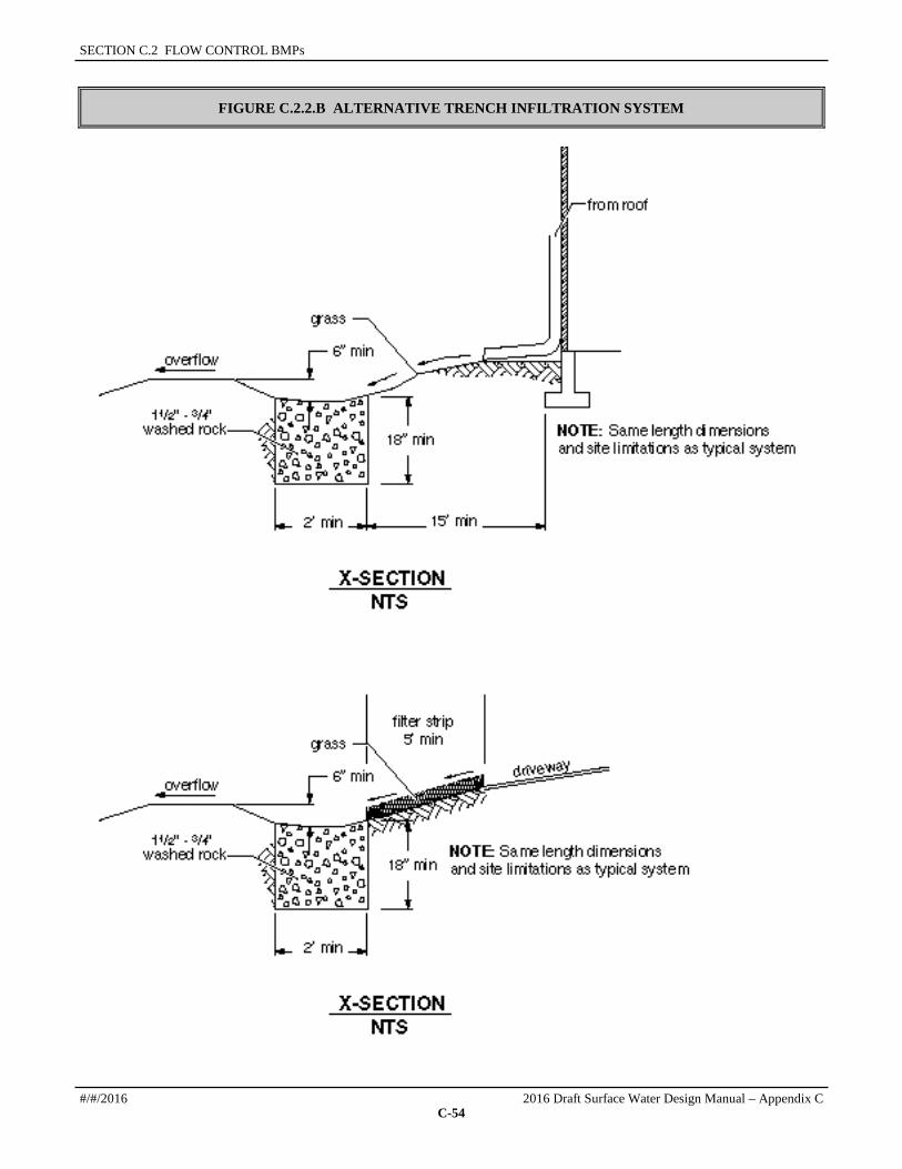
SECTION C.2 FLOW CONTROL BMPs
FIGURE C.2.2.B ALTERNATIVE TRENCH INFILTRATION SYSTEM
#/#/2016 2016 Draft Surface Water Design Manual – Appendix C
C-54

C.2.2 FULL INFILTRATION
FIGURE C.2.2.C TYPICAL DRYWELL INFILTRATION SYSTEM
Varies
2016 Draft Surface Water Design Manual – Appendix C #/#/2016
C-55

SECTION C.2 FLOW CONTROL BMPs
FIGURE C.2.2.D TYPICAL GROUND SURFACE DEPRESSION INFILTRATION SYSTEM
#/#/2016 2016 Draft Surface Water Design Manual – Appendix C
C-56

C.2.3 LIMITED INFILTRATION
C.2.3 LIMITED INFILTRATION Limited infiltration is the use of infiltration devices from Section C.2.2 in soils that are not as permeable as the medium sands or coarse sands/cobbles targeted for full infiltration in Section C.2.2. These less desirable soils include fine sands, loamy sands, sandy loams, and loams, which tend to be more variable in permeability, more frequently saturated during the wet season, and more prone to plugging over time. While full infiltration may be possible under the best of these soil conditions, in the long run, these conditions will conspire to limit average infiltration capacity to something much less than that of full infiltration. Therefore, using limited infiltration as specified in this section will not be credited the same as using full infiltration as specified in Section C.2.2.
Applicable Surfaces Subject to the minimum design requirements and specifications in this section, limited infiltration may be applied to any non- pollution generating impervious surface (e.g. approved roofs, sidewalks, or patio) and to those pollution generating impervious surfaces (e.g. driveway, road, or parking area) where the soil beneath the infiltration BMP has properties that reduce the risk of groundwater contamination from typical stormwater runoff or where a water quality facility provides treatment prior to infiltration as specified in Core Requirement #8 and Special Requirement #5 of the King County Surface Water Design Manual.
Infeasibility Criteria Limited infiltration is considered infeasible and not required for projects that cannot meet the minimum design requirements listed below. Where geotechnical evaluation and approval is required for limited infiltration that proposes to discharge towards or is within described setbacks of a steep slope hazard area, erosion hazard area, landslide hazard area, or slopes greater than 15%, limited infiltration is considered infeasible and not required. Though not required in these circumstances, a project proponent may still opt to use limited infiltration as long as the geotechnical evaluation and approval requirement is met.
Operation and Maintenance See Section C.2.3.5 (p. C-59).
C.2.3.1 REQUIRED SOILS REPORT In order to properly design limited infiltration devices, a soils report is required to identify soil types, soil characteristics, the depth to impermeable layers (i.e., hardpan) and to the maximum wet season groundwater level. Detailed requirements for the soils report are found under “Required Soils Report” in Section C.1.3. In many cases, this report will have already been prepared as required in Sections C.1.3.1 and C.1.3.2 for lots where full dispersion is not feasible or applicable to target impervious surface per Section C.2.1.
C.2.3.2 MINIMUM DESIGN REQUIREMENTS FOR LIMITED INFILTRATION The minimum requirements for limited infiltration are the same as those for full infiltration, except infiltration depressions are excluded and existing soils in the location of the infiltration device may be fine sands, loamy sands, sandy loams, or loams as opposed to only medium sands or better. Note that gravel and medium sand soils used for full infiltration correspond to Soil Types 1A, 1B, 2A and 2B in the Soil Textural Classification system used for onsite septic system design; fine sands are Type 3; and loamy sands, sandy loams and loams are Type 4 soils. Silt and clay loams, and cemented till (hardpan) are not suitable for limited infiltration systems.
2016 Draft Surface Water Design Manual – Appendix C #/#/2016
C-57

SECTION C.2 FLOW CONTROL BMPs
C.2.3.3 USE OF GRAVEL FILLED TRENCHES FOR LIMITED INFILTRATION The specifications for use of gravel filled trenches for limited infiltration are the same as those used for full infiltration, except that the required trench lengths are as follows:
For each 1,000 square feet of tributary impervious surface:
Inside the UGA (Rainfall region Seatac 1.0 and less): (a) 21 feet if the soil is a fine sand/loamy sand, (b) 36 feet if the soil is a sandy loam, or (c) 52 feet if the soil is a loam.
Inside the UGA (Rainfall regions greater than Seatac 1.0)): (d) 48.3 feet if the soil is a fine sand/loamy sand, (e) 60.5 feet if the soil is a sandy loam, or (f) 73 feet if the soil is a loam.
Outside the UGA: (g) 70 feet if the soil is a fine sand/loamy sand, (h) 121 feet if the soil is a sandy loam, or (i) 172 feet if the soil is a loam.
For each 1,000 square feet of tributary pervious surface:
Outside the UGA: (j) 3 feet if the soil is a fine sand/loamy sand, (k) 11 feet if the soil is a sandy loam, or (l) 19 feet if the soil is a loam.
C.2.3.4 USE OF DRYWELLS FOR LIMITED INFILTRATION The specifications for use of drywells for limited infiltration are the same as those used for full infiltration, except that the required gravel volumes are as follows:
For each 1,000 square feet of tributary impervious surface:
Inside the UGA: (a) 315 cubic feet if the soil is a fine sand/loamy sand, (b) 360 cubic feet if the soil is a sandy loam, or (c) 407 cubic feet if the soil is a loam.
Outside the UGA: (d) 406 cubic feet if the soil is a fine sand/loamy sand, (e) 560 cubic feet if the soil is a sandy loam, (f) 714 cubic feet if the soil is a loam.
For each 1,000 square feet of tributary pervious surface:
Outside the UGA: (g) 36 cubic feet if the soil is a fine sand/loamy sand, (h) 218 cubic feet if the soil is a sandy loam, or (i) 400 cubic feet if the soil is a loam.
NOTE: For projects using the BMP list approach to comply with Core Requirement 9 (Flow Control BMPs), the drywell sizing cited is restricted to configurations with a maximum depth of 5 feet and a minimum area footprint of 12.56 square feet. Projects that are using hydraulic modeling to demonstrate compliance with the LID Performance Standard to meet Core Requirement 9 (Flow Control BMPs) may propose deeper configurations subject to other applicable design criteria and limitations.
#/#/2016 2016 Draft Surface Water Design Manual – Appendix C
C-58

C.2.3 LIMITED INFILTRATION
C.2.3.5 MAINTENANCE INSTRUCTIONS FOR LIMITED INFILTRATION If the limited infiltration flow control BMP is proposed for a project, the following maintenance and operation instructions must be recorded as an attachment to the required declaration of covenant and grant of easement per Requirement 3 of Section C.1.3.4 (p. C-24). The intent of these instructions is to explain to future property owners, the purpose of the BMP and how it must be maintained and operated. These instructions are intended to be a minimum; DPER may require additional instructions based on site-specific conditions. Also, as the County gains more experience with the maintenance and operation of these BMPs, future updates to the instructions will be posted on King County's Surface Water Design Manual website.
TEXT OF INSTRUCTIONS Your property contains a stormwater management flow control BMP (best management practice) called "limited infiltration," which was installed to mitigate the stormwater quantity and quality impacts of some or all of the impervious surfaces on your property. Limited infiltration is a method of soaking runoff from impervious area (such as paved areas and roofs) into the ground. Infiltration devices, such as gravel filled trenches, drywells, and ground surface depressions, facilitate this process by putting runoff in direct contact with the soil and holding the runoff long enough to soak most of it into the ground. To be successful, the soil condition around the infiltration device must be able to soak water into the ground for a reasonable number of years.
The infiltration devices used on your property include the following as indicated on the flow control BMP site plan: gravel filled trenches, drywells. The size, placement, and composition of these devices as depicted by the flow control BMP site plan and design details must be maintained and may not be changed without written approval either from the King County Water and Land Resources Division or through a future development permit from King County.
Infiltration devices must be inspected annually and after major storm events to identify and repair any physical defects. Maintenance and operation of the system should focus on ensuring the system's viability by preventing sediment-laden flows from entering the device. Excessive sedimentation will result in a plugged or non-functioning facility. If the infiltration device has a catch basin, sediment accumulation must be removed on a yearly basis or more frequently if necessary. Prolonged ponding around or atop a device may indicate a plugged facility. If the device becomes plugged, it must be replaced. Keeping the areas that drain to infiltration devices well swept and clean will enhance the longevity of these devices. For roofs, frequent cleaning of gutters will reduce sediment loads to these devices.
2016 Draft Surface Water Design Manual – Appendix C #/#/2016
C-59

SECTION C.2 FLOW CONTROL BMPs
C.2.4 BASIC DISPERSION Basic dispersion is the application of dispersion devices that utilize any available capacity of onsite vegetated areas to mitigate the runoff quantity and quality impacts from developed surfaces (i.e., impervious and non-native pervious surfaces). The requirements for basic dispersion are less restrictive than full dispersion (Section C.2.1) in that any type of vegetation cover is allowed, the flowpath lengths through the vegetation are shorter, and there is no requirement to preserve native vegetated surface (e.g., forested surface) or minimize developed surface. As such, its mitigation of runoff impacts is significantly lower than that of full dispersion.
Applicable Surfaces Subject to the minimum design requirements and specifications in this section, basic dispersion may be applied to any impervious surface such as a roof, driveway, parking area, road, or sidewalk. Basic dispersion may also be used to disperse runoff from non-native pervious surface (e.g., lawns, landscaped areas, or pastures) if runoff from these surfaces is concentrated.
Infeasibility Criteria Basic dispersion is considered infeasible and not required for projects that cannot meet the minimum design requirements listed below. Where geotechnical evaluation and approval is required for basic dispersion that proposes to discharge towards or is within described setbacks of a steep slope hazard area, erosion hazard area, landslide hazard area, or slopes greater than 15%, basic dispersion is considered infeasible and not required. Though not required in these circumstances, a project proponent may still opt to use basic dispersion as long as the geotechnical evaluation and approval requirement is met.
Operation and Maintenance See Section C.2.4.6 (p. C-64).
C.2.4.1 MINIMUM DESIGN REQUIREMENTS FOR BASIC DISPERSION All of the following requirements must be met in order for basic dispersion to be applicable to a target impervious or pervious surface:
1. Runoff from the target impervious or pervious surface must be discharged using one of the following dispersion devices in accordance with the design specifications and maximum area of developed surface for each device as set forth in Sections C.2.4.2 through C.2.4.5:
• Splash blocks (see Section C.2.4.2, p. C-61)
• Rock pads (see Section C.2.4.3, p. C-62)
• Gravel filled trenches (see Section C.2.4.4, p. C-62)
• Sheet flow (see Section C.2.4.5, p. C-63)
2. Each device must discharge runoff such that it flows over a minimum distance of vegetated area called the "vegetated flowpath segment." The minimum distance, or length of the flowpath segment, is specified in the design specifications for each device. The "vegetated flowpath segment" itself must meet all of the following criteria:
a) The flowpath segment must be over well-established lawn or pasture, landscaping with well-established groundcover, or native vegetation with natural groundcover. The groundcover must be dense enough to help disperse and infiltrate flows and to prevent erosion.
b) The flowpath segment must be onsite or in an offsite tract or easement area reserved for such dispersion.
#/#/2016 2016 Draft Surface Water Design Manual – Appendix C
C-60

C.2.4 BASIC DISPERSION
c) The slope of the flowpath segment must be no steeper than 15% for any 20-foot reach of the flowpath segment.
d) The flowpath segment must be located between the dispersion device and any downstream impervious surface or drainage feature such as a pipe, ditch, stream, river, pond, lake, or wetland. All or a portion of the flowpath segment may be located within a critical area buffer.
3. For sites with septic systems, the discharge of runoff from dispersion devices must be located down slope of the primary and reserve drainfield areas. DPER permit review staff may waive this requirement if site topography clearly prohibits discharged flows from intersecting the drainfield.
4. Dispersion devices are not allowed in critical area buffers or on slopes steeper than 20%.
5. Dispersion devices are not allowed within 50 feet of a steep slope hazard area, erosion hazard area, or landslide hazard area.
6. Dispersion devices proposed on slopes steeper than 15% must be approved by a geotechnical engineer or engineering geologist unless otherwise approved by the DPER staff geologist. The geotechnical analysis must consider cumulative impacts from the project and surrounding areas under full built- out conditions.
7. Dispersion devices proposed near slopes steeper than 15% must be approved by a geotechnical engineer or engineering geologist if the facility is located within a setback from the top of slope equal to the total vertical height of the slope area that is steeper than 15% unless otherwise approved by the DPER staff geologist. The geotechnical analysis must consider cumulative impacts from the project and surrounding areas under full built- out conditions.
8. Dispersion devices that direct runoff toward a slope steeper than 15% may require evaluation and approval of the proposal by a geotechnical engineer or engineering geologist as determined by DPER. The geotechnical analysis must consider cumulative impacts from the project and surrounding areas under full built- out conditions.
9. Dispersion devices proposed within 200 feet of a steep slope hazard area, erosion hazard area, or landslide hazard area must be approved by a geotechnical engineer or engineering geologist unless otherwise approved by the DPER staff geologist. The geotechnical analysis must consider cumulative impacts from the project and surrounding areas under full built- out conditions.
10. The dispersion of runoff must not create flooding or erosion impacts as determined by the DPER. If runoff is discharged toward a landslide hazard area, erosion hazard area, or steep slope hazard area, DPER may require evaluation and approval of the proposal by a geotechnical engineer or engineering geologist. The geotechnical analysis must consider cumulative impacts from the project and surrounding areas under full built- out conditions.
C.2.4.2 USE OF SPLASH BLOCKS FOR BASIC DISPERSION Splash blocks are the simplest way to disperse flows from a roof area. Downspout splash blocks or downspout/drain extensions with splash blocks are often the only hardware required for this type of system. Vegetated flowpaths do the work of slowing and cleaning stormwater runoff. In general, if the ground is sloped away from the foundation, and there is adequate vegetation and area for effective dispersion, splash blocks will adequately disperse storm runoff. If the ground is fairly level, or if the structure includes a basement, or if foundation drains are proposed, splash blocks with downspout extensions may be a better choice because the discharge point is moved away from the foundation. Downspout extensions may include piping to a splash block that is a considerable distance from the roof downspout, provided the runoff can travel through a well-vegetated area as described below.
Uses: Roofs where runoff is collected and discharged via downspouts.
2016 Draft Surface Water Design Manual – Appendix C #/#/2016
C-61

SECTION C.2 FLOW CONTROL BMPs
Design Specifications Figure C.2.4.A (p. C-65) shows details of a roof downspout and splash block. The following specifications apply to use of splash blocks for basic dispersion:
1. No more than 700 square feet of roof area may be drained to a single splash block.
2. A "vegetated flowpath segment" of at least 50 feet in length must be available along the flowpath that runoff would follow upon discharge from the splash block.
3. For purposes of maintaining adequate separation of flows discharged from adjacent dispersion devices, the vegetated flowpath segment for the splash block must not overlap with other flowpath segments, except those associated with sheet flow from a non-native pervious surface.
C.2.4.3 USE OF ROCK PADS FOR BASIC DISPERSION Pads of crushed rock, 2 feet wide (perpendicular to flow) by 3 feet long by 6 inches deep, may be used as a dispersion device to discharge concentrated runoff from small amounts of impervious surface or non-native pervious surface.
Uses: Roofs, driveways, lawns, pasture, etc. from which runoff is concentrated in a downspout, gutter, pipe, yard drain, ditch, swale, etc.
Design Specifications Figure C.2.4.C (p. C-67) shows two possible ways of spreading flows from steep driveways. The following specifications apply to use of rock pads for basic dispersion:
1. No more than 700 square feet of impervious surface (or 5,000 square feet of non-native pervious surface) may be drained to a single rock pad.
2. A "vegetated flowpath segment" of at least 50 feet in length as illustrated in Figure C.2.4.C (p. C-67) must be available along the flowpath that runoff would follow upon discharge from the rock pad.
3. The pad of crushed rock shall be 2 feet wide by 3 feet long by 6 inches deep.
4. For purposes of maintaining adequate separation of flows discharged from adjacent dispersion devices, the vegetated flowpath segment for the rock pad must not overlap with other flowpath segments, except those associated with sheet flow from a non-native pervious surface.
C.2.4.4 USE OF GRAVEL FILLED TRENCHES FOR BASIC DISPERSION Where dispersion of concentrated flows through 50 feet of vegetation is not feasible, such as on a small or highly constrained site, a gravel filled trench (also called a dispersion trench) may be used to "unconcentrate" flows. Dispersion trenches provide some storage for runoff, promote infiltration, and spread concentrated flows so that a shorter vegetated flowpath length can be used at the trench outlet. This BMP is more expensive than the simple dispersion systems described above, and must be carefully constructed to be effective.
Uses: Roofs, driveways, lawns, pasture, etc. from which runoff is concentrated in a downspout, yard drain, pipe, drainage tile, etc.
Design Specifications Figure C.2.4.B (p. C-66) shows two types of dispersion trenches that may be used, a "simple 10-foot trench" and a maximum "50-foot trench with notch board." The 50-foot trench with notch board is further detailed in Figure C.2.1.D (p. C-42). These gravel filled trenches must meet the following specifications for basic dispersion:
#/#/2016 2016 Draft Surface Water Design Manual – Appendix C
C-62

C.2.4 BASIC DISPERSION
1. No more than 700 square feet of impervious surface (or 5,000 square feet of non-native pervious surface) may be drained to a simple 10-foot dispersion trench. Up to 3,500 square feet of impervious surface (or 25,000 square feet of non-native pervious surface) may be drained to a 50-foot trench with notch board. Smaller lengths of trench with notch board may be used at a ratio of 10 feet of trench per 700 square feet of impervious surface (or 5,000 square feet of non-native pervious surface).
2. A "vegetated flowpath segment" of at least 25 feet in length must be available along the flowpath that runoff would follow upon discharge from a dispersion trench. This length must be increased to 50 feet if the discharge is toward a steep slope hazard area or a landslide hazard area steeper than 15%. All or a portion of the vegetated flowpath segment may be within the buffer for the steep slope hazard area or landslide hazard area.
3. The simple 10-foot trench illustrated in Figure C.2.4.B must be at least 2-feet wide by 18-inches deep. The maximum 50-foot trench with notch board detailed in Figure C.2.1.D must be at least 2-feet wide by 24-inches deep.
4. All trenches must be filled with 3/4 to 11/2-inch washed rock.
5. All trenches must be placed at least 10 feet from any building and must be parallel as possible to the contour of the ground. A setback of at least 5 feet must be maintained between any edge of a trench and the property line.
6. For purposes of maintaining adequate separation of flows discharged from adjacent dispersion devices, the outer edge of the vegetated flowpath segment for the dispersion trench must not overlap with other flowpath segments, except those associated with sheet flow from a non-native pervious surface.
C.2.4.5 USE OF SHEET FLOW FOR BASIC DISPERSION Sheet flow, as a dispersion device, is the grading of a developed surface (either a strip of impervious surface or a width of non-native pervious surface) as needed to avoid the concentration of runoff before and after discharge from the surface. Two types of sheet flow, one for impervious surface and one for pervious surface, are detailed in this section.
Uses: Flat or moderately sloping surfaces (<15% slope) such as driveways, sport courts, patios, roofs without gutters, lawns, pastures, etc.; or any situation where concentration of flows can be avoided.
Design Specifications for Impervious Surface Sheet Flow (Basic Dispersion) Figure C.2.4.D (p. C-68) illustrates a typical use of sheet flow dispersion for impervious surface in accordance with the following specifications:
1. The strip of impervious surface may be either roof (with no gutter) or pavement. The edge of the target impervious strip and the ground adjacent to or immediately below the edge must be either level or sloped such that the direction of sheet flow is perpendicular to the edge or no more than 45 degrees from perpendicular.
2. A 2-foot-wide, 4-to-6 inch-deep, strip of crushed rock or the extended base course of a road or driveway must be provided at or below the edge of the impervious strip to facilitate dispersal of runoff. This requirement may be waived for use of reverse slope sidewalks18 and other impervious strips that are 10-feet wide or less.
3. A "vegetated flowpath segment" of at least 10 feet in length must be available along the flowpath that runoff would follow upon discharge from the strip of crushed rock.
18 Reverse slope sidewalk is one that slopes away from rather than onto the roadway it abuts as required by County road standards. If this technique is proposed within County right-of-way, a Road Variance will be required for its use.
2016 Draft Surface Water Design Manual – Appendix C #/#/2016
C-63
SECTION C.2 FLOW CONTROL BMPs
4. No more than a 20-foot-wide strip of impervious surface may be sheet flowed in this manner unless the length of vegetated flowpath segment is increased 10 feet for each additional 20 feet of impervious surface width or fraction thereof.
5. For purposes of maintaining adequate separation of flows discharged from adjacent dispersion devices, the outer edge of the vegetated flowpath segment for the strip of impervious surface must not overlap with other flowpath segments, except those associated with sheet flow from a non-native pervious surface.
Design Specifications for Pervious Surface Sheet Flow (Basic Dispersion) The runoff from any new pervious surface is considered dispersed by sheet flow if the runoff is not concentrated by a manmade or natural conveyance system (e.g., pipe, yard drain, drain tile, ditch, swale, etc.) within 25 feet of leaving the new pervious surface area or prior to leaving the site or entering a critical area buffer on the site.
C.2.4.6 MAINTENANCE INSTRUCTIONS FOR BASIC DISPERSION If the basic dispersion flow control BMP is proposed for a project, the following maintenance and operation instructions must be recorded as an attachment to the required declaration of covenant and grant of easement per Requirement 3 of Section C.1.3.4 (p. C-24). The intent of these instructions is to explain to future property owners, the purpose of the BMP and how it must be maintained and operated. These instructions are intended to be a minimum; DPER may require additional instructions based on site-specific conditions. Also, as the County gains more experience with the maintenance and operation of these BMPs, future updates to the instructions will be posted on King County's Surface Water Design Manual website.
TEXT OF INSTRUCTIONS FOR BASIC DISPERSION Your property contains a stormwater management flow control BMP (best management practice) called "basic dispersion," which was installed to mitigate the stormwater quantity and quality impacts of some or all of the impervious surfaces or non-native pervious surfaces on your property. Basic dispersion is a strategy for utilizing any available capacity of onsite vegetated areas to retain, absorb, and filter the runoff from developed surfaces. This flow control BMP has two primary components that must be maintained: (1) the devices that disperse runoff from the developed surfaces and (2) the vegetated area over which runoff is dispersed.
Dispersion Devices
The dispersion devices used on your property include the following as indicated on the flow control BMP site plan: splash blocks, rock pads, gravel filled trenches, sheet flow. The size, placement, composition, and downstream flowpaths of these devices as depicted by the flow control BMP site plan and design details must be maintained and may not be changed without written approval either from the King County Water and Land Resources Division or through a future development permit from King County.
Dispersion devices must be inspected annually and after major storm events to identify and repair any physical defects. When native soil is exposed or erosion channels are present, the sources of the erosion or concentrated flow need to be identified and mitigated. Concentrated flow can be mitigated by leveling the edge of the pervious area and/or realigning or replenishing the rocks in the dispersion device, such as in rock pads and gravel filled trenches.
Vegetated Flowpaths
The vegetated area over which runoff is dispersed must be maintained in good condition free of bare spots and obstructions that would concentrate flows.
#/#/2016 2016 Draft Surface Water Design Manual – Appendix C
C-64

C.2.4 BASIC DISPERSION
FIGURE C.2.4.A TYPICAL SPLASHBLOCK FOR BASIC DISPERSION
2016 Draft Surface Water Design Manual – Appendix C #/#/2016
C-65

SECTION C.2 FLOW CONTROL BMPs
FIGURE C.2.4.B TYPICAL GRAVEL-FILLED DISPERSION TRENCH FOR BASIC DISPERSION
25-Foot Vegetated Flowpath Segment
25-Foot Vegetated Flowpath Segment
Simple 10-foot trench
Maximum 50-foot trench w/notch board (see Figure C.2.1.D, p. C-42)
#/#/2016 2016 Draft Surface Water Design Manual – Appendix C
C-66

C.2.4 BASIC DISPERSION
FIGURE C.2.4.C EXAMPLES OF BASIC DISPERSION FOR STEEP DRIVEWAYS
segment
segment
Slot drain
2016 Draft Surface Water Design Manual – Appendix C #/#/2016
C-67

SECTION C.2 FLOW CONTROL BMPs
FIGURE C.2.4.D EXAMPLES OF BASIC DISPERSION FOR DRIVEWAYS
segment
10-foot Vegetated Flowpath Segment
#/#/2016 2016 Draft Surface Water Design Manual – Appendix C
C-68

C.2.5 FARMLAND DISPERSION
C.2.5 FARMLAND DISPERSION Farmland dispersion is the application of dispersion devices that utilize any available capacity of onsite pasture or croplands to mitigate the runoff quantity and quality impacts from developed surfaces (i.e., impervious and non-native pervious surfaces).
Applicable Surfaces Subject to the minimum design requirements and specifications in this section, farmland dispersion may be applied to any impervious surface or pervious surfaces related to an agricultural operation on sites within an Agricultural Production District (APD), Farmland Preservation Program (FPP), or site zoned “A” .
Infeasibility Criteria Farmland dispersion is an optional BMP. Projects proposing to use farmland dispersion must meet the minimum design requirements listed below.
Operation and Maintenance The area of cropland or pasture used for dispersion must be delineated as a “pasture/cropland retention area” on the flow control BMP site plan that will be attached to the required declaration of covenant and grant of easement per Requirement 3 of Section C.1.3.4 The required declaration of covenant and grant of easement must include an attachment that includes instructions for operating and maintaining dispersion devices as detailed in Section C.2.4.6.
C.2.5.1 MINIMUM DESIGN REQUIREMENTS FOR FARMLAND DISPERSION Farmland dispersion onto pasture and/or cropland is an allowed option if all of the following requirements are met for targeted impervious and pervious surfaces:
1. The project where farmland dispersion onto pasture or cropland is being considered must be currently in agricultural use and be within an Agricultural Production District (APD), Farmland Preservation Program (FPP), or site zoned “A”.
2. The impervious or pervious surface being dispersed onto pasture/cropland must be directly related to the agricultural operation.
3. New impervious and/or pervious surfaces being dispersed onto pasture/cropland must not disturb, impact, or replace native vegetation.
4. The soil moisture holding capacity of new pervious surfaces must be protected in accordance with KCC 16.82.100(F) and (G). KCC 16.82.100(F) requires that the duff layer or native topsoil be retained to the maximum extent practicable. KCC 16.82.100(G) requires soil amendment to mitigate for lost moisture holding capacity where compaction or removal of some or all of the duff layer or underlying topsoil has occurred. The specifications for compost in the soil amendment can be found in Reference 11-C.
5. Dispersion of pollution generating impervious surfaces and/or pollution generating pervious surfaces exceeding the water quality facility thresholds of Core Requirement 8 onto pasture/cropland is only allowed without a water quality facility where the site has a functioning farm management plan that emphasizes water quality improvement. Where there is no active farm management plan, the pollution generating surface dispersed is considered a target surface for water quality treatment and a facility from the SWDM must be provided per Core Requirement 8.
6. The runoff being dispersed must be discharged using one of the following dispersion devices in accordance with the design specifications and maximum area of dispersed surface for each device as set forth in Sections C.2.1.3 through C.2.1.6:
• Splash blocks (see Section C.2.1.3, p. C-34) 2016 Draft Surface Water Design Manual – Appendix C #/#/2016
C-69

SECTION C.2 FLOW CONTROL BMPs
• Rock pads (see Section C.2.1.4, p. C-35)
• Gravel filled trenches (see Section C.2.1.5, p. C-35)
• Sheet flow (see Section C.2.1.6, p. C-37)
7. A pasture/cropland flowpath segment of at least 100 feet in length must be available along the flowpath that runoff would follow upon discharge from a dispersion device. The flowpath segment must meet all of the following criteria:
a) The flowpath segment must be over pasture/cropland.
b) The width of the flowpath segment shall be as specified in #6 above based on the type of dispersion device being used.
c) The minimum length of the flowpath segment shall be as specified in #6 above based on the amount of impervious area being dispersed and the type of dispersion device being used. This length shall be extended as needed to achieve a total dispersion area (length times width) that is at least 10 times the area of impervious surface being dispersed.
d) The flowpath segment must be onsite or in an offsite tract or easement area reserved for such dispersion.
e) The slope of the flowpath segment must be no steeper than 15% for any 20-foot reach of the flowpath segment.
f) The flowpath segment must be located between the dispersion device and any downstream drainage feature such as a pipe, ditch, stream, river, pond, lake, or wetland.
g) The flowpath segments for adjacent dispersion devices must be sufficiently spaced in order to prevent overlap of flows in the segment areas. The minimum spacing between flowpath segments is specified for each dispersion device in previous sections, and includes an exception made in cases where sheet flow from a non-native pervious surface overlaps with other flowpath segments.
8. The area of cropland or pasture used for dispersion must be delineated as a “pasture/cropland retention area” on the flow control BMP site plan that will be attached to the required declaration of covenant and grant of easement per Requirement 3 of Section C.1.3.4.
9. For sites with septic systems, the discharge of runoff from dispersion devices must be located down slope of the primary and reserve drainfield areas. DPER permit review staff can waive this requirement if site topography clearly prohibits discharged flows from intersecting the drainfield.
10. Dispersion devices are not allowed in critical area buffers (unless approved by DPER) or on slopes steeper than 20%.
11. Dispersion devices are not allowed within 50 feet of a steep slope hazard area, erosion hazard area, or landslide hazard area.
12. Dispersion devices proposed on slopes steeper than 15% must be approved by a geotechnical engineer or engineering geologist unless otherwise approved by the DPER staff geologist. The geotechnical analysis must consider cumulative impacts from the project and surrounding areas under full built- out conditions.
13. Dispersion devices proposed near slopes steeper than 15% must be approved by a geotechnical engineer or engineering geologist unless otherwise approved by the DPER staff geologist if the facility is located within a setback from the top of slope equal to the total vertical height of the slope area that is steeper than 15%. The geotechnical analysis must consider cumulative impacts from the project and surrounding areas under full built-out conditions.
14. Dispersion devices that direct runoff toward a slope steeper than 15% may require evaluation and approval of the proposal by a geotechnical engineer or engineering geologist as determined by DPER.
#/#/2016 2016 Draft Surface Water Design Manual – Appendix C
C-70

C.2.5 FARMLAND DISPERSION
The geotechnical analysis must consider cumulative impacts from the project and surrounding areas under full built- out conditions.
15. Dispersion devices proposed within 200 feet of a steep slope hazard area, erosion hazard area, or landslide hazard area must be approved by a geotechnical engineer or engineering geologist unless otherwise approved by the DPER staff geologist. The geotechnical analysis must consider cumulative impacts from the project and surrounding areas under full built- out conditions.
16. The dispersion of runoff must not create flooding or erosion impacts as determined by the DPER. If runoff is discharged toward a landslide hazard area, erosion hazard area, or steep slope hazard area, DPER may require evaluation and approval of the proposal by a geotechnical engineer or engineering geologist. The geotechnical analysis must consider cumulative impacts from the project and surrounding areas under full built- out conditions.
C.2.6 BIORETENTION Bioretention areas are shallow landscaped depressions, with a designed soil mix and plants adapted to the local climate and soil moisture conditions that receive stormwater from a contributing area. Four types of bioretention designs are discussed in this section: bioretention cells, bioretention swales, bioretention planters, and a road-side ditch bioretention alternative design. These are briefly described below:
Bioretention cells: Shallow depressions with a designed planting soil mix and a variety of plant material, including trees, shrubs, grasses, and/or other herbaceous plants. Bioretention cells are not designed as a conveyance system. (See Figures 2.6.A and 2.6.B)
Bioretention swales: Incorporate the same design features as bioretention cells; however, bioretention swales are designed as part of a system that can convey stormwater when maximum ponding depth is exceeded. Bioretention swales have relatively gentle side slopes and ponding depths that are typically 6 to 12 inches.
Bioretention planters: Designed soil mix and a variety of plant material including trees, shrubs, grasses, and/or other herbaceous plants within a vertical walled container usually constructed from formed concrete, but could include other materials. Planters have an open bottom and allow infiltration to the subgrade. These designs are often used in ultra-urban settings.
Road-side bioretention ditch: This feature uses a designed soil mix underlain by drain rock for increased storage, low maintenance vegetation typical of road-side ditches, and requires no permanent ponding-- allowing for road side conveyance to function per current design and maintenance standards without need for weirs or excess standing water along the road. Where a bioretention cell or swale would be deemed infeasible for a project, the road side bioretention ditch is considered as optional, not required.
Applicable Surfaces Subject to the minimum design requirements and specifications in this section, bioretention may be applied to any impervious surface such as a roof, driveway, parking area, road, or sidewalk, and to any non-native pervious surface such as a lawn, landscaped area, or pasture. Bioretention proposed in road right-of-ways must be per the King County Road Design and Construction Standards (KCRDCS) or as otherwise approved by the King County Road Engineer.
Infeasibility Criteria Bioretention is considered infeasible and not required for projects that cannot meet the minimum design requirements for bioretention or via the bioretention infeasibility criteria list that follows in this section.
2016 Draft Surface Water Design Manual – Appendix C #/#/2016
C-71

SECTION C.2 FLOW CONTROL BMPs
Where the minimum design requirements call for geotechnical evaluation and approval for bioretention that proposes to discharge towards or is within described setbacks of a steep slope hazard area, erosion hazard area, landslide hazard area, or slopes greater than 15%, bioretention is considered infeasible and not required. Though not required in these circumstances, a project proponent may still opt to use bioretention as long as the geotechnical evaluation and approval requirement is met.
Additional Requirements for Large Bioretention Facilities: Bioretention that receives runoff from:
• impervious surfaces totaling 10,000 square feet or more; or
• new pervious surfaces totaling ¾ acre or more, or
• a combination of impervious and pervious surfaces that results in a 0.15 cfs increase (using 15 minute time steps) or 0.1 cfs (using 1 hour timesteps) in the 100 year peak flow when comparing predeveloped (historic) and developed conditions,
must meet the following additional requirements to address their larger size, risk, and maintenance needs:
Bioretention Cells:
• Section 5.2 (KCSWDM): 100 year overflow conveyance (if applicable); Spill Control Device; Presettling, Protection from Upstream Erosion; Facility Construction Guidelines; Offsite Groundwater Impacts; Groundwater Protection; Infiltration near Water Supply Wells; and Infiltration near Steep Slopes and Landslide Hazard Areas.
• Section 5.2.2.1 Infiltration Ponds Design Criteria: General, Setbacks.
Bioretention Swales:
• Section 5.2 (KCSWDM): 100 year overflow conveyance (if applicable); Protection from Upstream Erosion; Facility Construction Guidelines; Offsite Groundwater Impacts; Groundwater Protection; Infiltration near Water Supply Wells; and Infiltration near Steep Slopes and Landslide Hazard Areas.
• Section 6.3 (KCSWDM) Vegetated Flowpath Facility Designs: Access; Construction Considerations; Flow Velocity, Energy Dissipation, and Flow Spreading (#2, 3, 4 and #5)
Other Site Suitability Factors: Utility conflicts: Consult local jurisdiction requirements for horizontal and vertical separation required for publicly-owned utilities, such as water and sewer. Consult the appropriate franchise utility owners for separation requirements from their utilities, which may include communications and gas. When separation requirements cannot be met, designs should include appropriate mitigation measures, such as impermeable liners over the utility, sleeving utilities, fixing known leaky joints or cracked conduits, and/or adding an underdrain to the bioretention.
Transportation safety: The design configuration and selected plant types should provide adequate sight distances, clear zones, and appropriate setbacks for roadway applications in accordance with local jurisdiction requirements.
Ponding depth and surface water draw-down: Flow control needs, as well as location in the development, and mosquito breeding cycles will determine draw-down timing. For example, front yards and entrances to residential or commercial developments may require rapid surface dewatering for aesthetics.
Impacts of surrounding activities: Human activity influences the location of the facility in the development. For example, locate bioretention areas away from traveled areas on individual lots to prevent soil compaction and damage to vegetation or provide elevated or bermed pathways in areas where foot traffic is inevitable. and provide barriers, such as wheel stops, to restrict vehicle access in roadside applications.
#/#/2016 2016 Draft Surface Water Design Manual – Appendix C
C-72

C.2.6 BIORETENTION
Visual buffering: Bioretention facilities can be used to buffer structures from roads, enhance privacy among residences, and for an aesthetic site feature.
Site growing characteristics and plant selection: Appropriate plants should be selected for sun exposure, soil moisture, and adjacent plant communities. Native species or hardy cultivars are recommended and can flourish in the properly designed and placed Bioretention Soil Mix with no nutrient or pesticide inputs and 2-3 years irrigation for establishment. Invasive species control may be necessary.
Required Soils Report Many locations in King County have soils that are underlain by a compacted layer of soil (i.e., glacial till or hardpan) which severely limits soaking capacity and causes water to perch on the relatively impervious layer during the wet season. This can make bioretention impracticable, unreliable, and reduce plant survivability in the bioretention system. Thus, a soils report is necessary to identify soil types, depth to impermeable layers (hardpan) or the maximum wet season groundwater level, and infiltration rates. Detailed requirements for the soils report are found under “Required Soils Report” in Section C.1.3.
Operation and Maintenance See Section 2.6.3
Bioretention Infeasibility Criteria List These are conditions that make bioretention not required to be implemented as part of the prescriptive BMP lists detailed in Core Requirement 9 of the SWDM and Section 1.3 of Appendix C, that require BMPs to be evaluated and installed to the maximum extent feasible. Where determined infeasible by these criteria, an applicant has the option to propose a functional design via the adjustment process described in Section 1.4 of the SWDM in order to: (a) use the FCBMP facility modeling credits described in SWDM Section 1.2.9.3; (b) to use in achieving the LID Performance Standard (where required or optional);or (c) to meet the minimum FCBMP implementation requirements ensconced in the “Small Lot, Large Lot, and Large Rural Lot requirements” lists located in SWDM Section 1.2.9.1 and Appendix C, Section 1.3.
Note: Criteria with setback distances are as measured from the bottom edge of the bioretention soil mix.
Citation of any of the following infeasibility criteria (#1-7) must be based on an evaluation of site-specific conditions and a written recommendation from an appropriate licensed professional (e.g., engineer, geologist, hydrogeologist):
1. Where professional geotechnical evaluation recommends infiltration not be used due to reasonable concerns about erosion, slope failure, or down gradient flooding.
2. Within an area whose ground water drains into an erosion hazard, or landslide hazard area.
3. Where the only area available for siting would threaten the safety or reliability of pre-existing underground utilities, pre-existing underground storage tanks, pre-existing structures, or pre-existing road or parking lot surfaces.
4. Where the only area available for siting does not allow for a safe overflow pathway to the municipal separate storm sewer system or private storm sewer system.
5. Where there is a lack of usable space for bioretention facilities at re-development sites, or where there is insufficient space within the existing public right-of-way on public road projects.
6. Where infiltrating water would threaten existing below grade basements.
7. Where infiltrating water would threaten shoreline structures such as bulkheads.
The following criteria can be cited as reasons for a finding of infeasibility without further justification (though some require professional services):
8. Within setbacks from structures as established by the local government with jurisdiction.
2016 Draft Surface Water Design Manual – Appendix C #/#/2016
C-73

SECTION C.2 FLOW CONTROL BMPs
9. Where they are not compatible with surrounding drainage system as determined by the local government with jurisdiction (e.g., project drains to an existing stormwater collection system whose elevation or location precludes connection to a properly functioning bioretention facility).
10. Where land for bioretention is within area designated as an erosion hazard, or landslide hazard.
11. Where the site cannot be reasonably designed to locate bioretention facilities on slopes less than 8%.
12. Within 50 feet from the top of slopes that are greater than 20% and over 10 feet of vertical relief.
13. For properties with known soil or ground water contamination (typically federal Superfund sites or state cleanup sites under the Model Toxics Control Act (MTCA)):
a) Within 100 feet of an area known to have deep soil contamination;
b) Where ground water modeling indicates infiltration will likely increase or change the direction of the migration of pollutants in the ground water;
c) Wherever surface soils have been found to be contaminated unless those soils are removed within 10 horizontal feet from the infiltration area;
d) Any area where these facilities are prohibited by an approved cleanup plan under the state Model Toxics Control Act or Federal Superfund Law, or an environmental covenant under Chapter 64.70 RCW.
14. Within 100 feet of a closed or active landfill.
15. Within 100 feet of a drinking water well, or a spring used for drinking water supply.
16. Within 10 feet of small on-site sewage disposal drainfield, including reserve areas, and grey water reuse systems. For setbacks from a “large on-site sewage disposal system”, see Chapter 246-272B WAC.
17. Within 10 feet of an underground storage tank and connecting underground pipes when the capacity of the tank and pipe system is 1100 gallons or less. (As used in these criteria, an underground storage tank means any tank used to store petroleum products, chemicals, or liquid hazardous wastes of which 10% or more of the storage volume (including volume in the connecting piping system) is beneath the ground surface.
18. Within 100 feet of an underground storage tank and connecting underground pipes when the capacity of the tank and pipe system is greater than 1100 gallons.
19. Where the minimum vertical separation of 1 foot to the seasonal high water table, bedrock, or other impervious layer would not be achieved below bioretention that would serve a drainage area that is: 1) less than 5,000 sq. ft. of pollution-generating impervious surface, and 2) less than 10,000 sq. ft. of impervious surface; and, 3) less than ¾ acres of pervious surface.
20. Where the a minimum vertical separation of 3 feet to the seasonal high water table, bedrock or other impervious layer would not be achieved below bioretention that: 1) would serve a drainage area that meets or exceeds: a) 5,000 square feet of pollution-generating impervious surface, or b) 10,000 square feet of impervious surface, or c) three-quarter (3/4) acres of pervious surfaces; and 2) cannot reasonably be broken down into amounts smaller than indicated in (1).
21. Where the field testing indicates potential bioretention sites have a measured (a.k.a., initial) native soil saturated hydraulic conductivity less than 0.30 inches per hour.
C.2.6.1 MINIMUM DESIGN REQUIREMENTS (CELLS, SWALES, AND PLANTERS) All of the following requirements must be met in order for bioretention to be applicable to a target impervious or pervious surface:
1. A minimum water storage volume shall be provided in the bioretention BMP that is calculated by multiplying the equivalent storage depth by the square footage of the target surface area served:
#/#/2016 2016 Draft Surface Water Design Manual – Appendix C
C-74

C.2.6 BIORETENTION
For target impervious areas:
• Inside the UGA (Rainfall region SeaTac 1.0 and less ): In till soils, provide bioretention volume based on 0.6 inches of equivalent storage depth; in outwash soils provide bioretention volume based on 0.1 inches of equivalent storage depth
• Inside the UGA (Rainfall regions greater than SeaTac 1.0): In till soils, provide bioretention volume based on 0.8 inches of equivalent storage depth; in outwash soils, provide bioretention volume based on 0.4 inches of equivalent storage depth,
• Outside the UGA: In till soils, provide bioretention volume based on 1.9 inches of equivalent storage depth; in outwash soils provide bioretention volume based on 1.0 inches of equivalent storage depth
For target pervious areas: In till soils, provide bioretention volume based on 0.7 inches of equivalent storage depth; in outwash soils, provide bioretention volume based on 0.006 inches of equivalent storage depth.
2. The water storage area, containing the minimum required storage volume, shall be 6-12 inches deep at overflow and have side slopes no steeper than 3 horizontal to 1 vertical. The overflow point of the water storage area shall be at least 6 inches below any adjacent pavement area. The overflow point must be situated so that overflow does not cause erosion damage or unplanned inundation.
3. The bioretention footprint as measured at the overflow elevation shall be a minimum of 5% of the impervious surface directed to the bioretention BMP.
4. The maximum allowable drawdown time of the water storage area is 24 hours. A correction factor of 0.33 to 1 (no correction factor) as recommended by a licensed geotechnical engineer or engineering geologist should be applied to initial measured infiltration rates of the in situ soils to determine the design rate for this drawdown calculation. The designed depth of ponding (6” minimum to 12” maximum) must be considered in light of the drawdown time requirement (e.g. in slow draining soils, the designed ponding depth may need to be decreased to the minimum 6” in order to meet the drawdown criteria). As an example, a 6” deep pool with an initial measured rate of .5”/hour and a correction factor of 0.5 applied will achieve drawdown in exactly 24 hours (0.5 in/hour x 0.5 correction factor x 24 hours = 6 inches). Where drawdown criteria described cannot be achieved without installation of underdrains, bioretention is considered infeasible and not required.
5. Bioretention with underdrains is not allowed unless approved via a SWDM adjustment per Section 1.4 that , at minimum, addresses comparable hydraulic performance, water quality concerns, and maintainability.
6. Bioretention areas should have a minimum shoulder of 12 inches between the road edge and beginning of the bioretention side slope where flush curbs are used.
7. Flow entrance techniques for energy dissipation shall be utilized and may include: flow spreaders described in Section 6.2.6 of SWDM, gravel flow spreaders described in Section 6.3.4.2 of SWDM, rock pads for pipe flow entrances, and/or catch basins preceding bioretention where high sediment loads are anticipated. Other equivalent options may be considered.
8. If a containment berm is used to form the water storage area, the berm must be at least 2 feet wide and 6 inches above the 12 inches of water depth. A catch basin or rock pad must be provided to release water when the pond's water level exceeds the 12 inches of water depth. The catch basin may discharge to the local drainage system or other acceptable discharge location via a 4-inch rigid pipe. The rock pad may be used with or without a constructed drainage system downstream. If a rock pad is used, it must be composed of crushed rock, 6-inches deep and 2 feet wide (perpendicular to flow) and must extend at least 4 feet or beyond the containment berm, whichever is greater. The rock pad must be situated so that overflow does not cause erosion damage or unplanned inundation.
2016 Draft Surface Water Design Manual – Appendix C #/#/2016
C-75

SECTION C.2 FLOW CONTROL BMPs
9. An 18” thick bioretention soil mix liner extending up slopes to maximum storage depth is required in the bioretention cell, swale, or planter. The bioretention soil mix shall be per Reference 11-C. Compost shall meet Specification 1 described in Reference 11-C.
10. Do not use filter fabrics between the subgrade and the Bioretention Soil Mix. The gradation between existing soils and Bioretention Soil Mix is not great enough to allow significant migration of fines into the Bioretention Soil Mix. Additionally, filter fabrics may clog with downward migration of fines from the Bioretention Soil Mix.
11. On-site soil mixing or placement shall not be performed if Bioretention Soil Mix or subgrade soil is saturated. The bioretention soil mixture should be placed and graded by machinery operating adjacent to the bioretention facility.
12. If machinery must operate in the bioretention cell for soil placement, use light weight equipment with low ground-contact pressure. The soil mixture shall be placed in horizontal layers not to exceed 12 inches per lift for the entire area of the bioretention facility.
13. Compact the Bioretention Soil Mix to a relative compaction of 85 percent of modified maximum dry density (ASTM D 1557). Compaction can be achieved by boot packing (simply walking over all areas of each lift), and then apply 0.2 inches (0.5 cm) of water per 1 inch (2.5 cm) of Bioretention Soil Mix depth. Water for settling should be applied by spraying or sprinkling.
14. Prior to placement of the BSM, the finished subgrade shall: (A) Be scarified to a minimum depth of 3 inches; (B) have any sediment deposited from construction runoff removed (To remove all introduced sediment, subgrade soil should be removed to a depth of 3-6 inches and replaced with BSM); and (C) Be inspected by the responsible engineer to verify required subgrade condition.
15. If using the default bioretention soil mix described in Reference 11-C, pre-placement laboratory analysis for saturated hydraulic conductivity of the bioretention soil mix is not required. Verification of the mineral aggregate gradation, compliance with the compost specifications, and the mix ratio must be provided.
16. Custom bioretention soil mixes may be considered under the adjustment process described in Section 1.4.
17. Water tolerant plants such as those in Table C.2.66.A shall be planted in the pond bottom. Plants native to Western Washington are preferred.
18. A minimum 5-foot setback shall be maintained between any part of a bioretention cell, swale, or planter and any structure or property line.
19. Bioretention constructed with imported compost materials are not allowed within one-quarter mile of a sensitive lake if the underlying native soil does not meet the soil suitability criteria for treatment in Section 5.2.1.
20. Bioretention constructed with imported compost materials are not allowed within ¼ mile of those waterbodies listed as category 2, 4, or 5 for either nutrients or low DO determined to be caused by nutrients. These waterbodies are found on Ecology’s combined 303(d)/305(b) Water Quality Assessment list. The exception to this prohibition is where phosphorous is the identified nutrient and the underlying native soil meets soil suitability criteria for treatment described in Section 5.2.1.
21. Bioretention swales shall have a minimum 2- foot bottom width. Swales shall be flat in cross section to promote even flow across the width of the swale. See KCRDCS for design details for bioretention swales in the ROW.
22. Bioretetention swales shall meet the conveyance requirements described in Section 1.2.4.1 of the KCSWDM. Maximum 100 year peak flow velocity through bioretention swales is 3 feet per second.
23. Maximum longitudinal (along direction of flow) slope of bioretention swales shall be 6%.
#/#/2016 2016 Draft Surface Water Design Manual – Appendix C
C-76

C.2.6 BIORETENTION
24. For sites with septic systems, bioretention must be located downgradient of the primary and reserve drainfield areas. DPER permit review staff can waive this requirement if site topography clearly prohibits subsurface flows from intersecting the drainfield.
25. Bioretention is not allowed in critical area buffers or on slopes steeper than 20%.
26. Bioretention is not allowed within 50 feet of a steep slope hazard area, erosion hazard area, or landslide hazard area.
27. Bioretention proposed on slopes steeper than 15% must be approved by a geotechnical engineer or engineering geologist unless otherwise approved by the DPER staff geologist. The geotechnical analysis must consider cumulative impacts from the project and surrounding areas under full built- out conditions.
28. Bioretention proposed near slopes steeper than 15% must be approved by a geotechnical engineer or engineering geologist if the facility is located within a setback from the top of slope equal to the total vertical height of the slope area that is steeper than 15% unless otherwise approved by the DPER staff geologist. The geotechnical analysis must consider cumulative impacts from the project and surrounding areas under full built- out conditions.
29. Bioretention that directs overflow towards slopes steeper than 15% may require evaluation and approval of the proposal by a geotechnical engineer or engineering geologist as determined by DPER. The geotechnical analysis must consider cumulative impacts from the project and surrounding areas under full built- out conditions.
30. Bioretention proposed within 200 feet of a steep slope hazard area, erosion hazard area, or landslide hazard area must be approved by a geotechnical engineer or engineering geologist unless otherwise approved by the DPER staff geologist. The geotechnical analysis must consider cumulative impacts from the project and surrounding areas under full built- out conditions.
31. Bioretention must not create flooding or erosion impacts as determined by DPER. If bioretention is proposed near or directs overflows towards a landslide hazard area, erosion hazard area, or a steep slope hazard area, DPER may require evaluation and approval of the proposal by a geotechnical engineer or engineering geologist. The geotechnical analysis must consider cumulative impacts from the project and surrounding areas under full built- out conditions.
C.2.6.2 MINIMUM DESIGN REQUIREMENTS (ROADSIDE BIORETENTION DITCH) All of the following requirements must be met in order for bioretention to be applicable to a target impervious surface:
1. The roadside bioretention ditch is only allowed to serve right of way improvements (e.g. roads, sidewalks).
2. The roadside bioretention ditch is considered optional only and not required for purposes of complying the prescriptive BMP list approach from Core Requirement 9 where a standard bioretention cell is deemed infeasible.
3. The longitudinal slope of the road side bioretention ditch shall be consistent with KCRDCS 7.02.A standards for grass-lined ditches which allows a maximum slope of 6%. Grades between 3% and 6% may require check dams to reduce potential erosion.
4. The roadside bioretention ditch shall meet the conveyance requirements described in Section 1.2.4.1 of the KCSWDM.
5. Flow entrance techniques for energy dissipation shall be utilized and may include where applicable: flow spreaders described in Section 6.2.6 of SWDM, gravel flow spreaders described in Section 6.3.4.2 of SWDM, rock pads for pipe flow entrances, and/or catch basins preceding bioretention where high sediment loads are anticipated. Other equivalent options may be considered.
2016 Draft Surface Water Design Manual – Appendix C #/#/2016
C-77

SECTION C.2 FLOW CONTROL BMPs
Consideration should be given as to whether the design details specified in Section 4.2.2 (Outfalls) are applicable to a given design.
6. Side slopes shall be per KCRDCS standards for roadside ditches.
7. Vegetation in the roadside bioretention ditch shall conform to the KCRDCS for grass lined road ditches.
8. A minimum 2 ft. wide, 18” thick bioretention soil mix liner is required along the full length of the roadside bioretention ditch. The bioretention soil mix shall be per Reference 11-C. Compost shall meet Specification 1 described in Reference 11-C.
9. A linear trench of washed rock that is 1.5 ft. deep x 2 ft. wide (typical ditch bottom width) shall be placed underneath the bioretention soil mix liner. The length of the trench shall be that specified in Section C.2.3.3 “Use of Gravel Filled Trenches for Limited Infiltration” based on the tributary area to the roadside bioretention ditch. Where this length is not achievable, the width of the gravel trench may be widened as allowed by ROW or tract width to provide an equivalent area footprint. To slow flows and encourage infiltration, the gravel filled trench shall be broken up along every 50 feet its length by a minimum 4 foot long plug of native, unexcavated soil or native material (or equivalent) free of wood waste, debris, clods or rocks greater than 6” in any dimension, compacted to 95% maximum density (ASTM D1557).
10. Do not use filter fabrics between the subgrade and the Bioretention Soil Mix. The gradation between existing soils and Bioretention Soil Mix is not great enough to allow significant migration of fines into the Bioretention Soil Mix. Additionally, filter fabrics may clog with downward migration of fines from the Bioretention Soil Mix.
11. On-site soil mixing or placement shall not be performed if Bioretention Soil Mix or subgrade soil is saturated. The bioretention soil mixture should be placed and graded by machinery operating adjacent to the bioretention facility.
12. If machinery must operate in the bioretention cell for soil placement, use light weight equipment with low ground-contact pressure. The soil mixture shall be placed in horizontal layers not to exceed 12 inches per lift for the entire area of the bioretention facility.
13. Compact the Bioretention Soil Mix to a relative compaction of 85 percent of modified maximum dry density (ASTM D 1557). Compaction can be achieved by boot packing (simply walking over all areas of each lift), and then apply 0.2 inches (0.5 cm) of water per 1 inch (2.5 cm) of Bioretention Soil Mix depth. Water for settling should be applied by spraying or sprinkling.
14. Prior to placement of the BSM, the finished subgrade shall: (A) Be scarified to a minimum depth of 3 inches; (B) have any sediment deposited from construction runoff removed (To remove all introduced sediment, subgrade soil should be removed to a depth of 3-6 inches and replaced with BSM); and (C) Be inspected by the responsible engineer to verify required subgrade condition.
15. If using the default bioretention soil mix described in Reference 11-C, pre-placement laboratory analysis for saturated hydraulic conductivity of the bioretention soil mix is not required. Verification of the mineral aggregate gradation, compliance with the compost specifications, and the mix ratio must be provided.
16. Custom bioretention soil mixes may be considered under the adjustment process described in Section 1.4.
17. Bioretention with underdrains is not allowed unless approved via a SWDM adjustment per Section 1.4 that ,at minimum, addresses comparable hydraulic performance, water quality concerns, and maintainability.
18. Bioretention constructed with imported compost materials are not allowed within one-quarter mile of a sensitive lake if the underlying native soil does not meet the soil suitability criteria for treatment in Section 5.2.1.
#/#/2016 2016 Draft Surface Water Design Manual – Appendix C
C-78

C.2.6 BIORETENTION
19. Bioretention constructed with imported compost materials are not allowed within ¼ mile of those waterbodies listed as category 2, 4, or 5 for either nutrients or low DO determined to be caused by nutrients. These waterbodies are found on Ecology’s combined 303(d)/305(b) Water Quality Assessment list. The exception to this prohibition is where phosphorous is the identified nutrient and the underlying native soil meets soil suitability criteria for treatment described in Section 5.2.1.
20. For sites with septic systems, bioretention must be located downgradient of the primary and reserve drainfield areas. DPER permit review staff can waive this requirement if site topography clearly prohibits subsurface flows from intersecting the drainfield.
21. Bioretention is not allowed in critical area buffers or on slopes steeper than 20%.
22. Bioretention is not allowed within 50 feet of a steep slope hazard area, erosion hazard area, or landslide hazard area.
23. Bioretention proposed on slopes steeper than 15% must be approved by a geotechnical engineer or engineering geologist unless otherwise approved by the DPER staff geologist. The geotechnical analysis must consider cumulative impacts from the project and surrounding areas under full built- out conditions.
24. Bioretention proposed near slopes steeper than 15% must be approved by a geotechnical engineer or engineering geologist if the facility is located within a setback from the top of slope equal to the total vertical height of the slope area that is steeper than 15% unless otherwise approved by the DPER staff geologist. The geotechnical analysis must consider cumulative impacts from the project and surrounding areas under full built- out conditions.
25. Bioretention that directs overflow towards slopes steeper than 15% may require evaluation and approval of the proposal by a geotechnical engineer or engineering geologist as determined by DPER.
26. Bioretention proposed within 200 feet of a steep slope hazard area, erosion hazard area, or landslide hazard area must be approved by a geotechnical engineer or engineering geologist unless otherwise approved by the DPER staff geologist. The geotechnical analysis must consider cumulative impacts from the project and surrounding areas under full built- out conditions.
27. Bioretention must not create flooding or erosion impacts as determined by DPER. If bioretention is proposed near or directs overflow towards a landslide hazard area, erosion hazard area, or a steep slope hazard area, DPER may require evaluation and approval of the proposal by a geotechnical engineer or engineering geologist. The geotechnical analysis must consider cumulative impacts from the project and surrounding areas under full built- out conditions.
2016 Draft Surface Water Design Manual – Appendix C #/#/2016
C-79

SECTION C.2 FLOW CONTROL BMPs
C.2.6.3 MAINTENANCE INSTRUCTIONS FOR BIORETENTION If a bioretention flow control BMP is proposed for a project, the following maintenance and operation instructions must be recorded as an attachment to the required declaration of covenant and grant of easement per Requirement 3 of Section C.1.3.4 (p. C-24). The intent of these instructions is to explain to future property owners, the purpose of the BMP and how it must be maintained and operated. These instructions are intended to be a minimum; DPER may require additional instructions based on site-specific conditions. Also, as the County gains more experience with the maintenance and operation of these BMPs, future updates to the instructions will be posted on King County's Surface Water Design Manual website.
TEXT OF INSTRUCTIONS Your property contains a stormwater management flow control BMP (best management practice) called "bioretention," which was installed to mitigate the stormwater quantity and quality impacts of some or all of the impervious or non-native pervious surfaces on your property. Bioretention includes vegetated closed depressions (ponds), swales, and/or planters that retain and filter stormwater from an area of impervious surface or non-native pervious surface. The soil in the bioretention area has been enhanced to encourage and support vigorous plant growth that serves to filter the water and sustain infiltration capacity. Depending on soil conditions, the bioretention area may have water in them throughout the wet season and may overflow during major storm events.
The size, placement, and design of the bioretention BMP as depicted by the flow control BMP site plan and design details must be maintained and may not be changed without written approval either from the King County Water and Land Resources Division or through a future development permit from King County. Plant materials may be changed to suit tastes, but chemical fertilizers and pesticides must not be used. Mulch may be added and additional compost should be worked into the soil over time.
Bioretention BMPs must be inspected annually for physical defects. After major storm events, the system should be checked to see that the overflow system is working properly. If erosion channels or bare spots are evident, they should be stabilized with soil, plant material, mulch, or landscape rock. A supplemental watering program may be needed the first year to ensure the long-term survival of the bioretention BMP. Vegetation should be maintained as follows: 1) replace all dead vegetation as soon as possible; 2) remove fallen leaves and debris as needed; 3) remove all noxious vegetation when discovered; 4) manually weed without herbicides or pesticides; 5) during drought conditions, use mulch to prevent excess solar damage and water loss.
#/#/2016 2016 Draft Surface Water Design Manual – Appendix C
C-80

C.2.6 BIORETENTION
TABLE C.2.66.A WATER TOLERANT PLANTS
Common Name Scientific Name Spacing (on center)
Western mannagrass Glyceria occidentalis seed
Velvetgrass Holcus mollis seed
Shortawn foxtail Alopecurus aequalis seed
Water foxtail Alopecurus geniculatus seed
Spike rush Eleocharis spp. 4 inches
Slough sedge Carex obnupta 6 inches or seed
Sawbeak sedge Carex stipata 6 inches
Sedge Carex spp. 6 inches
Slender rush Juncus tenuis 6 inches
Water parsley Oenanthe sarmentosa 6 inches
Hardstem bulrush Scirpus acutus 6 inches
Watercress Rorippa nasturtium-aquaticum 12 inches
Small-fruited bulrush Scirpus microcarpus 12 inches
C.2.6.4 EXAMPLE SIZING CALCULATION Runoff Source: 20-foot by 20-foot driveway
Equivalent Storage Depth = 1.0 inches (0.083 feet)
Bioretention Storage Volume Needed = 20 feet x 20 feet x 0.083 feet = 33 cubic feet
Note that if the design soil percolation rate is 0.5 inches per hour, a pond 1-foot deep will take 24 hours to drain when filled.
2016 Draft Surface Water Design Manual – Appendix C #/#/2016
C-81

SECTION C.2 FLOW CONTROL BMPs
FIGURE C.2.6.A TYPICAL BIORETENTION CELL
FIGURE UNDER MODIFICATION
#/#/2016 2016 Draft Surface Water Design Manual – Appendix C
C-82

C.2.6 BIORETENTION
FIGURE C.2.6.B TYPICAL BIORETENTION WITH CONTAINMENT BERM
FIGURE UNDER MODIFICATION
2016 Draft Surface Water Design Manual – Appendix C #/#/2016
C-83

SECTION C.2 FLOW CONTROL BMPs
C.2.7 PERMEABLE PAVEMENT Permeable pavements include porous concrete, porous asphalt, cellular confinement gravel systems, unit pavers with a gravel bed, and grassed modular grid systems. There are many types of permeable pavement on the market today. Permeable pavement systems require careful design, construction, and maintenance in order to provide good service life and proper drainage. Manufacturer's recommendations should be strictly followed for proprietary systems.
Applicable Surfaces Subject to the minimum design requirements and specifications in this section, permeable pavement may be applied to non- pollution generating impervious surface (sidewalks or patio) and to those pollution generating impervious surfaces (e.g. driveway, road, or parking area) where the soil beneath the infiltration BMP has properties that reduce the risk of groundwater contamination from typical stormwater runoff . Note that where the soil beneath the infiltration BMP does not have properties that reduce the risk of groundwater contamination, the applicant has the option of using permeable pavement for residential driveways serving 2 or less households that are not within a groundwater protection area if a 6” sand liner beneath the permeable pavement is included in the design. Permeable pavement proposed for roadway improvements (e.g. roads and sidewalks) shall be per the King County Road Design and Construction Standards (KCRDCS) or as otherwise approved by the King County Road Engineer.
Design Considerations Application of permeable pavement on steeper slopes may not be suitable because water draining through permeable base may daylight downslope. Ideally, permeable pavement slopes should be less than 5%. Areas with a high water table or highly impervious soils may be unsuitable for this pavement type.
Runoff from other impervious areas (“run on”) may be directed to permeable pavements that meet the following criteria:
Inside Urban Growth Area boundary: Run-on area is limited to a maximum of 5 times the permeable pavement area to which the run-on is directed.
Outside the Urban Growth Area boundary: In till soils, run-on area is limited to a maximum of 2 times the permeable pavement area to which the run-on is directed. In outwash soils, run-on area is limited a maximum of 5 times the permeable pavement area to which the run-on is directed.
Run-on from pollution generating impervious surfaces is only allowed in areas where the soil beneath the permeable pavement has properties that reduce the risk of groundwater contamination and is limited to a maximum of 2 times the permeable pavement area to which the run-on is directed.
For permeable pavement installations on slopes greater than 5%, impermeable check dams are required underneath the pavement. The surface area of the impermeable check dams shall not be counted as part of the permeable pavement when determining the allowable area of run-on.
Target impervious surfaces from which runoff is directed to permeable pavements are considered to have met the minimum FCBMP implementation requirements contained in the “Small Lot, Large Lot, and Large Rural Lot requirements” lists located in SWDM Section 1.2.9.1 and Appendix C, Section 1.3. No FCBMP modeling credits for sizing flow control or water quality facilities are given for surfaces that are run-on to permeable pavements.
Infeasibility Criteria Permeable pavement is considered infeasible and not required for projects that cannot meet the minimum design requirements for permeable pavement described or via the permeable pavement infeasibility criteria list below. Where the minimum design requirements call for geotechnical evaluation and approval for permeable pavement that proposes to discharge towards or is within described setbacks of a steep slope hazard area, erosion hazard area, landslide hazard area, or slopes greater than 15%, permeable
#/#/2016 2016 Draft Surface Water Design Manual – Appendix C
C-84

C.2.7 PERMEABLE PAVEMENT
pavement is considered infeasible and not required. Though not required in these circumstances, a project proponent may still opt to use permeable pavement as long as the geotechnical evaluation and approval requirement is met. Functionally equivalent design alternatives to permeable pavement may be considered to meet BMP requirements if approved by both WLRD and DPER. A functionally equivalent design will provide the same infiltrative capacity (storage and infiltration rate) or be demonstrated via modeling to meet the LID Performance Standard. An example of an equivalent design includes a standard impermeable pavement design where runoff is collected and redistributed /infiltrated below or adjacent to the pavement.
Required Soils Report Many locations in King County have soils that are underlain by a compacted layer of soil (i.e., glacial till or hardpan) which severely limits soaking capacity and causes water to perch on the relatively impervious layer during the wet season. In other areas, soil does not have the properties that reduce the risk of groundwater contamination from typical stormwater runoff from pollution generating surfaces. These factors can make permeable pavements impractical, unreliable, or deleterious to groundwater quality. Thus, a soils report is necessary to identify soil types, soil characteristics, depth to impermeable layers (hardpan) or the maximum wet season groundwater level, and infiltration rates.
Detailed requirements for the soils report are found under “Required Soils Report” in Section 1.3.
Operation and Maintenance See Section C.2.7.7 (p. C-91).
Permeable Pavement Infeasibility Criteria List These are conditions that make permeable pavement not required to be implemented as part of the prescriptive BMP lists detailed in Core Requirement 9 of the SWDM and Section 1.3 of Appendix C, that require BMPs to be evaluated and installed to the maximum extent feasible. Where determined infeasible by these criteria, an applicant has the option to propose a functional design via the adjustment process described in Section 1.4 of the SWDM in order to: (a) use the FCBMP facility modeling credits described in SWDM Section 1.2.9.3; (b) to use in achieving the LID Performance Standard (where required or optional);or (c) to meet the minimum FCBMP implementation requirements contained in the “Small Lot, Large Lot, and Large Rural Lot requirements” lists located in SWDM Section 1.2.9.1 and Appendix C, Section 1.3.
These criteria also apply to impervious pavements that would employ stormwater collection from the surface of impervious pavement with redistribution below the pavement.
Citation of any of the following infeasibility criteria must be based on an evaluation of site-specific conditions and a written recommendation from an appropriate licensed professional (e.g, engineer, geologist, hydrogeologist).
1. Where professional geotechnical evaluation recommends infiltration not be used due to reasonable concerns about erosion, slope failure, or down gradient flooding.
2. Within an area whose ground water drains into an erosion hazard, or landslide hazard area.
3. Where infiltrating and ponded water below new permeable pavement area would compromise adjacent impervious pavements.
4. Where infiltrating water below a new permeable pavement area would threaten existing below grade basements.
5. Where infiltrating water would threaten shoreline structures such as bulkheads.
6. Down slope of steep, erosion prone areas that are likely to deliver sediment.
7. Where fill soils are used that can become unstable when saturated.
2016 Draft Surface Water Design Manual – Appendix C #/#/2016
C-85

SECTION C.2 FLOW CONTROL BMPs
8. Excessively steep slopes where water within the aggregate base layer or at the sub-grade surface cannot be controlled by detention structures and may cause erosion and structural failure, or where surface runoff velocities may preclude adequate infiltration at the pavement surface.
9. Where permeable pavements can not provide sufficient strength to support heavy loads at industrial facilities such as ports.
10. Where installation of permeable pavement would threaten the safety or reliability of pre-existing underground utilities, pre-existing underground storage tanks, or pre-existing road sub-grades.
The following criteria can be cited as reasons for a finding of infeasibility without further justification (though some require professional services to make the observation):
11. Within an area designated as an erosion hazard, or landslide hazard.
12. Within 50 feet from the top of slopes that are greater than 20%.
13. For properties with known soil or ground water contamination (typically federal Superfund sites or state cleanup sites under the Model Toxics Control Act (MTCA)):
a) Within 100 feet of an area known to have deep soil contamination;
b) Where ground water modeling indicates infiltration will likely increase or change the direction of the migration of pollutants in the ground water;
c) Wherever surface soils have been found to be contaminated unless those soils are removed within 10 horizontal feet from the infiltration area;
d) Any area where these facilities are prohibited by an approved cleanup plan under the state Model Toxics Control Act or Federal Superfund Law, or an environmental covenant under Chapter 64.70 RCW.
14. Within 100 feet of a closed or active landfill.
15. Within 100 feet of a drinking water well, or a spring used for drinking water supply, if the pavement is a pollution-generating surface.
16. Within 10 feet of a small on-site sewage disposal drainfield, including reserve areas, and grey water reuse systems. For setbacks from a “large on-site sewage disposal system”, see Chapter 246-272B WAC.
17. Within 10 feet of any underground storage tank and connecting underground pipes, regardless of tank size. As used in these criteria, an underground storage tank means any tank used to store petroleum products, chemicals, or liquid hazardous wastes of which 10% or more of the storage volume (including volume in the connecting piping system) is beneath the ground surface.
18. At multi-level parking garages, and over culverts and bridges.
19. Where the site design cannot avoid putting pavement in areas likely to have long-term excessive sediment deposition after construction (e.g., construction and landscaping material yards).
20. Where the site cannot reasonably be designed to have a porous asphalt surface at less than 5 percent slope, or a pervious concrete surface at less than 10 percent slope, or a permeable interlocking concrete pavement surface (where appropriate) at less than 12 percent slope. Grid systems upper slope limit can range from 6 to 12 percent; check with manufacturer and local supplier.
21. Where the native soils below a pollution-generating permeable pavement (e.g., road or parking lot) do not meet the soil suitability criteria for providing treatment (See Section 5.2.1). Note that where the soil beneath the infiltration BMP does not have properties that reduce the risk of groundwater contamination, the applicant has the option of using permeable pavement for residential driveways serving 2 or less households that are not within a groundwater protection area if a 6” sand liner beneath the permeable pavement is included in the design. This approach is optional and does not
#/#/2016 2016 Draft Surface Water Design Manual – Appendix C
C-86

C.2.7 PERMEABLE PAVEMENT
make permeable pavement required to be implemented as part of the prescriptive BMP lists detailed in Core Requirement 9 of the SWDM and Section 1.3 of Appendix C.
22. Where seasonal high ground water or an underlying impermeable/low permeable layer would create saturated conditions within one foot of the bottom of the lowest gravel base course.
23. Where underlying soils are unsuitable for supporting traffic loads when saturated. Soils meeting a California Bearing Ratio of 5% are considered suitable for residential access roads.
24. Where appropriate field testing indicates soils have a measured (a.k.a., initial) native soil saturated hydraulic conductivity less than 0.3 inches per hour.
25. Roads that receive more than very low traffic volumes, and areas having more than very low truck traffic. Roads with a projected average daily traffic volume of 400 vehicles or less are very low volume roads (AASHTO, 2001) (U.S. Dept. of Transportation, 2013). Areas with very low truck traffic volumes are roads and other areas not subject to through truck traffic but may receive up to weekly use by utility trucks (e.g., garbage, recycling), daily school bus use, and multiple daily use by pick-up trucks, mail/parcel delivery trucks, and maintenance vehicles. Note: This infeasibility criterion does not extend to sidewalks and other non-traffic bearing surfaces.
26. Where replacing existing impervious surfaces unless the existing surface is a non-pollution generating surface over an outwash soil with a saturated hydraulic conductivity of four inches per hour or greater.
27. At sites defined as “high use sites”.
28. In areas with “industrial activity” as identified in 40 CFR 122.26(b)(14).
29. Where the risk of concentrated pollutant spills is more likely such as gas stations, truck stops, and industrial chemical storage sites.
30. Where routine, heavy applications of sand occur in frequent snow zones to maintain traction during weeks of snow and ice accumulation.
C.2.7.1 MINIMUM DESIGN REQUIREMENTS All of the following requirements must be met in order for permeable pavement to be applicable to a target impervious surface:
1. One of the following types of permeable pavement must be used in accordance with the design specifications for each type as set forth in Sections C.2.7.2 through C.2.7.6:
• Porous concrete (see Section C.2.7.2, p. C-88)
• Porous asphaltic concrete (see Section C.2.7.3, p. C-89)
• Permeable pavers (see Section C.2.7.4, p. C-89)
• Modular grid pavement (see Section C.2.7.5, p. C-89)
• Grassed modular grid pavement (see Section C.2.7.6, p. C-90)
2. Permeable pavements shall be installed in accordance with the manufacturer's specifications, except when such specifications are less stringent than those set forth in Sections C.2.7.2 through C.2.7.6.
3. Permeable pavements shall not be placed on slopes steeper than 5% for porous asphaltic concrete and 10% for all other types.
4. For permeable pavements placed on slopes steeper than 5% , impermeable check dams shall be placed on the subgrade and below the pavement surface with the intent to increase infiltration, improve flow attenuation, and reduce structural problems associated with subgrade erosion on slopes. Check dams should have an overflow drain invert placed at the maximum ponding depth created by the check dam. Based on an assumed 5” check dam height in a 6” thick gravel storage base, check dam spacing shall range from 4 feet on center for 10% slopes to 8 feet on center for 5% slopes and interpolated linearly
2016 Draft Surface Water Design Manual – Appendix C #/#/2016
C-87

SECTION C.2 FLOW CONTROL BMPs
for slopes in between. At minimum, one check dam shall be provided at the toe of the subgrade/downstream limit of the permeable pavement section. Check dams used to achieve LID Performance modeling shall be placed as required by the design—note that the area of the check dams is not counted as part of the infiltrative footprint when modeling.
5. Permeable pavements that are pollution generating are only allowed where the underlying soils meet criteria for groundwater protection defined in Section 5.2.1with the single exception that where the soil beneath the infiltration BMP does not have properties that reduce the risk of groundwater contamination, the applicant has the option of using permeable pavement for residential driveways serving 2 or less households that are not within a groundwater protection area if a 6” sand liner beneath the permeable pavement is included in the design. This approach is optional and does not make permeable pavement required to be implemented as part of the prescriptive BMP lists detailed in Core Requirement 9 of the SWDM and Section 1.3 of Appendix C.
6. Permeable pavement is not allowed within 50 feet of a steep slope hazard area, erosion hazard area, or landslide hazard area.
7. Permeable pavement proposed near slopes steeper than 15% must be approved by a geotechnical engineer or engineering geologist unless otherwise approved by the DPER staff geologist if the facility is located within a setback from the top of slope equal to the total vertical height of the slope area that is steeper than 15%. The geotechnical analysis must consider cumulative impacts from the project and surrounding areas under full built- out conditions.
8. Permeable pavement that directs overflow towards slopes steeper than 15% may require evaluation and approval of the proposal by a geotechnical engineer or engineering geologist unless otherwise approved by the DPER staff geologist. The geotechnical analysis must consider cumulative impacts from the project and surrounding areas under full built- out conditions.
9. Permeable pavement proposed within 200 feet of a steep slope hazard area, erosion hazard area, or landslide hazard area must be approved by a geotechnical engineer or engineering geologist unless otherwise approved by the DPER staff geologist.
10. Permeable pavement must not create flooding or erosion impacts as determined by DPER. If permeable pavement is proposed near or directs overflow towards a landslide hazard area, erosion hazard area, or a steep slope hazard area, DPER may require evaluation and approval of the proposal by a geotechnical engineer or engineering geologist. The geotechnical analysis must consider cumulative impacts from the project and surrounding areas under full built- out conditions.
C.2.7.2 POROUS CONCRETE Porous concrete consists of a mix of aggregate, cement paste, water and admixtures, but contains less fine aggregate than conventional concrete. Voids in the hardened concrete allow water to drain through the surface into the subgrade.
Uses: Sidewalks, patios, parking areas, and driveways.
Design Specifications 1. A minimum of 6 inches of free-draining sand or gravel base is required under the porous concrete
surface.
2. The free-draining base shall have less than 5% fines (material passing the #200 sieve) based on the fraction passing the #4 sieve.
3. The porous concrete pavement shall be permeable enough to absorb water at a minimum rate of 10 inches per hour immediately after the pavement surface has been wetted continuously for at least 10 minutes. Compliance with this minimum rate shall be checked prior to construction approval of the pavement. Compliance may be checked using a simple bucket test in which 5 gallons of water are poured onto the pavement surface all at once from a 5-gallon bucket. If nothing but a scant amount of
#/#/2016 2016 Draft Surface Water Design Manual – Appendix C
C-88

C.2.7 PERMEABLE PAVEMENT
water puddles or runs off the surface, then the pavement is considered to meet the minimum rate of absorption. If this test is not conclusive, then a 6-inch ring sealed at the base to the pavement surface shall be used to measure the actual rate of absorption.
4. Porous concrete sidewalks placed in road right-of-way or on private property subject to vehicle loading shall be a minimum of 5 inches thick and shall have a minimum 28-day compressive strength of 3000 psi.
5. Sidewalks and patios on private property not subject to vehicles shall be a minimum of 4 inches thick and should have a minimum 28-day compressive strength of 2000 psi.
C.2.7.3 POROUS ASPHALTIC CONCRETE Porous asphaltic concrete uses a mix that contains less fine aggregate than conventional asphaltic concrete. Voids in the pavement allow water to drain through the surface into the subgrade.
Uses: Sidewalks, patios, parking areas, and driveways.
Design Specifications Same as for porous concrete, except that the compressive strength specifications do not apply and the pavement section shall be as needed to provide a service life equivalent to conventional asphaltic concrete.
C.2.7.4 PERMEABLE PAVERS Permeable pavers provide a solid surface but allow natural drainage and migration of water into the earth by permitting water to drain through the spaces between the pavers. On the Internet, there are a number of manufacturers and installers.
Uses: Sidewalks, patios, parking areas, and driveways.
Design Specifications Same as for porous concrete, except that the compressive strength specifications do not apply and the pavement thickness shall be as specified by the manufacturer or a civil engineer.
C.2.7.5 MODULAR GRID PAVEMENT Modular grid pavement consists of a lattice of concrete, plastic, or other load bearing material over a permeable base of gravel or sand (or both). On the Internet, there is information on several manufacturers of the modular grid materials used for such pavement. These materials include plastic lattice, concrete pavers, or special forms for a cast-in-place concrete grid. These systems use a confining structure incorporated into the subgrade with an engineered fill material.
Uses: Low-traffic or infrequently used areas such as low-traffic driveways, overflow parking, event parking, church parking, employee parking, maintenance access roads, etc.; they are not allowed road right-of-ways.
Design Specifications 1. A minimum of 6 inches of free draining base material (sand or gravel) is required under the modular
grid material.
2. The modular grid material must be installed according to the manufacturer's instructions.
3. The surface area of the modular grid openings must be at least 50% of the total surface area of the modular grid pavement.
4. The modular grid openings must be filled with gravel, sand, or a mixture of both.
2016 Draft Surface Water Design Manual – Appendix C #/#/2016
C-89

SECTION C.2 FLOW CONTROL BMPs
5. Smooth surface walkways may be run across modular grid pavements, provided the impervious surfaced walkways do not exceed 10 percent of the total pavement surface.
C.2.7.6 GRASSED MODULAR GRID PAVEMENT Grassed modular grid pavement is basically a modular grid pavement with grass planted in the openings or in a thin layer of soil over the grid material. The benefits of this measure are reduced runoff peaks and volumes resulting from the increased infiltration of stormwater, the increased water storage provided in the grid soil and base, and the increased evapotranspiration provided by the grass. The grassed surface also helps remove pollutants that are left behind by vehicles.
Uses: Low-traffic or infrequently used areas such as low-traffic driveways, overflow parking, event parking, church parking, employee parking, maintenance access roads, etc.; they are not allowed road right-of-ways.
Design Specifications 1. A minimum of 6 inches of free draining base material (sand or gravel) is required under the modular
grid material.
2. The modular grid material must be installed according to the manufacturer's instructions.
3. The surface area of the modular grid openings must be at least 50% of the total surface area of the modular grid pavement.
4. The modular grid openings must be filled with a sandy soil mix suitable for growing grass as specified by the manufacturer's instructions or a landscape architect.
5. Smooth surface walkways may be run across modular grid pavements, provided the impervious surfaced walkways do not exceed 10 percent of the total pavement area.
#/#/2016 2016 Draft Surface Water Design Manual – Appendix C
C-90

C.2.7 PERMEABLE PAVEMENT
C.2.7.7 MAINTENANCE INSTRUCTIONS FOR PERMEABLE PAVEMENT If the permeable pavement flow control BMP is proposed for a project, the following maintenance and operation instructions, plus any provided by the manufacturer or installer, must be recorded as an attachment to the required declaration of covenant and grant of easement per Requirement 3 of Section C.1.3.4 (p. C-24). The intent of these instructions is to explain to future property owners, the purpose of the BMP and how it must be maintained and operated. These instructions are intended to be a minimum; DPER may require additional instructions based on site-specific conditions or manufacturer's recommendations. Also, as the County gains more experience with the maintenance and operation of these BMPs, future updates to these instructions will be posted on King County's Surface Water Design Manual website.
TEXT OF INSTRUCTIONS FOR NON-VEGETATED PERMEABLE PAVEMENT Your property contains a stormwater management flow control BMP (best management practice) called "permeable pavement," which was installed to minimize the stormwater quantity and quality impacts of some or all of the paved surfaces on your property. Permeable pavements reduce the amount of rainfall that becomes runoff by allowing water to seep through the pavement into a free-draining gravel or sand bed, where it can be infiltrated into the ground.
The type(s) of permeable pavement used on your property is: porous concrete, porous asphaltic concrete, permeable pavers, modular grid pavement.
The area covered by permeable pavement as depicted by the flow control BMP site plan and design details must be maintained as permeable pavement and may not be changed without written approval either from the King County Water and Land Resources Division or through a future development permit from King County.
Permeable pavements must be inspected after one major storm each year to make sure it is working properly. Prolonged ponding or standing water on the pavement surface is a sign that the system is defective and may need to be replaced. If this occurs, contact the pavement installer or the King County Water and Land Resources Division for further instructions. A typical permeable pavement system has a life expectancy of approximately 25-years. To help extend the useful life of the system, the surface of the permeable pavement should be kept clean and free of leaves, debris, and sediment through regular sweeping or vacuum sweeping. The owner is responsible for the repair of all ruts, deformation, and/or broken paving units.
TEXT OF INSTRUCTIONS FOR VEGETATED PERMEABLE PAVEMENT Your property contains a stormwater management flow control BMP (best management practice) called "grassed modular grid pavement," which was installed to minimize the stormwater quantity and quality impacts of some or all of the paved surfaces on your property. Grassed modular grid pavement has the runoff characteristics of a lawn while providing the weight-bearing capacity of concrete pavement. The grassed surface not only minimizes runoff quantity, it helps to filter pollutants generating by vehicular use of the surface.
The composition and area of grassed modular grid pavement as depicted by the flow control BMP site plan and design details must be maintained and may not be changed without written approval either from the King County Water and Land Resources Division or through a future development permit from King County.
Grassed modular grid pavement must be inspected after one major storm each year to make sure it is working properly. Prolonged ponding or standing water on the pavement surface is a sign that the system defective and may need to be replaced. If this occurs, contact the pavement installer or the King County Water and Land Resources Division for further instructions. The grassed surface of the pavement must be regularly mowed and maintained in a good condition. Bare spots must be replanted in the spring or fall.
2016 Draft Surface Water Design Manual – Appendix C #/#/2016
C-91

SECTION C.2 FLOW CONTROL BMPs
C.2.8 RAINWATER HARVESTING Rainwater harvesting means the collection and storage of roof runoff for domestic or irrigation uses. Rainwater harvesting systems include a collection area, a filter, a storage device and an outflow device. Storage may be above ground or below grade and may consist of tanks or vaults. Example configurations are shown in Figure C.2.8.A (p. C-93) and Figure C.2.8.B (p. C-93). The stored water may be used for any domestic purpose including irrigation. The distribution system may be gravity or pumped.
Applicable Surfaces Subject to the minimum design requirements and specifications in this section, rainwater harvesting systems may be used with any roof area.
Design Considerations Provisional specifications available in the State UBC for commercial rainwater systems may be used for guidance in designing the various elements of a non-commercial system. Note that a water right may be required to collect and use rainwater.
Operation and Maintenance See Section C.2.8.2 (p. C-94) and Minimum Design Requirement 2 below.
C.2.8.1 MINIMUM DESIGN REQUIREMENTS All of the following requirements must be met in order for rainwater harvesting to be applicable to a target impervious surface:
1. For a rainwater harvesting system proposed to be used towards meeting Core 3 (Flow Control) or Core 9 (Flow Control BMPs) requirements, an approved drainage adjustment is required that demonstrates the system’s impact/benefit and specifies conditions of use to achieve the same.
2. To assure the system functions as designed and provides the required stormwater management, system-specific maintenance and operation instructions must be submitted and approved by DPER. Such instructions should be prepared by the system's manufacturer or installer.
3. A minimum 5-foot setback shall be maintained between any part of the rainwater harvesting system and any property line.
#/#/2016 2016 Draft Surface Water Design Manual – Appendix C
C-92

C.2.8 RAINWATER HARVESTING
FIGURE C.2.8.A TYPICAL ABOVE GROUND RESERVOIR CONFIGURATION (STENSROD, 1978)
FIGURE C.2.8.B VARIOUS POSSIBLE RESERVOIR CONFIGURATIONS (STENSROD, 1978)
2016 Draft Surface Water Design Manual – Appendix C #/#/2016
C-93

SECTION C.2 FLOW CONTROL BMPs
C.2.8.2 MAINTENANCE INSTRUCTIONS FOR RAINWATER HARVESTING If the rainwater harvesting flow control BMP is proposed for a project, the following maintenance and operation instructions must be incorporated into the maintenance and operation instructions required per Minimum Design Requirement 2. All such instructions must be recorded as an attachment to the required declaration of covenant and grant of easement per Requirement 3 of Section C.1.3.4 (p. C-24). The intent of these instructions is to explain to future property owners, the purpose of the BMP and how it must be maintained and operated. These instructions are intended to be a minimum; DPER may require additional instructions based on site-specific conditions or manufacturer's recommendations. Also, as the County gains more experience with the maintenance and operation of these BMPs, future updates to these instructions will be posted on King County's Surface Water Design Manual website.
TEXT OF INSTRUCTIONS Your property contains a stormwater management flow control BMP (best management practice) called "rainwater harvesting," which was installed to minimize the stormwater runoff impacts of impervious surface on your property. Rainwater harvesting is a means for the collection and storage of roof runoff for domestic or irrigation use. Rainwater harvesting systems include a collection area, a filtering system, a storage device, and an outflow device.
The size, components, and configuration of the rainwater system as depicted by the flow control BMP site plan and design details must be maintained and may not be changed without written approval either from the King County Water and Land Resources Division or through a future development permit from King County.
The collection area (e.g., roof) should be routinely inspected for debris and other material that could impede the entrance and/or exit of surface flows. The filtering system should be periodically inspected for effectiveness and replaced or replenished as recommended by the manufacturer. The storage device must be drained completely during the dry season (May 1st - September 30th) and/or as otherwise described in the SWDM adjustment approval in order to provide the needed capacity for an entire wet season. A maintenance log should be kept on site with the aforementioned information and dates of maintenance performance. King County inspection staff may request to view the maintenance log at any time.
#/#/2016 2016 Draft Surface Water Design Manual – Appendix C
C-94

C.2.9 REDUCED IMPERVIOUS SURFACE CREDIT
C.2.9 REDUCED IMPERVIOUS SURFACE CREDIT Reduced impervious surface credit means a credit toward meeting impervious surface flow control BMP requirements through application of techniques that result in less impervious surface coverage than is typically constructed or allowed for a particular land use. The credit may be used to mitigate for impervious surface to which flow control BMPs must be applied as specified by BMP Requirement 3 in either Section C.1.3.1.A (p. C-19) or Section C.1.3.2.A (p. C-21).
To receive the credit, a reduction in impervious surface below established norms must be assured through covenant and/or alternative design of impervious surfaces as described in the subsections below. For every square foot of reduced impervious surface assured, an equal area of actual proposed target impervious surface may be credited as mitigated, provided the runoff from the credited area is either directed to vegetated pervious areas on the site or discharged through a perforated pipe connection per Section C.2.11 (p. C-102).
Applicable Surfaces Subject to the minimum design requirements and specifications in this section, the reduced impervious surface credit may be applied to any impervious surface such as a roof, driveway, parking area, or road.
Operation and Maintenance See Section C.2.9.7 (p. C-98).
C.2.9.1 MINIMUM DESIGN REQUIREMENTS All of the following requirements must be met in order for the reduced impervious surface credit to be applicable to a target impervious surface:
1. One or more of the following techniques must be used to reduce, restrict, or otherwise mitigate for impervious surface subject to flow control BMPs:
• Restricted footprint (see Section C.2.9.2 below)
• Wheel strip driveways (see Section C.2.9.3, p. C-96)
• Minimum disturbance foundation (see Section C.2.9.4, p. C-96)
• Open grid decking over pervious surface (see Section C.2.9.5, p. C-96)
2. The area of target impervious surface credited as mitigated by the reduced impervious surface credit must meet all of the following requirements:
a) The area credited as mitigated must be no more than 10,000 square feet on any one site/lot unless the surface is served by a flow control facility designed by a civil engineer in accordance with Section 1.2.3 of the SWDM.
b) Any runoff from the area credited as mitigated must be directed to vegetated pervious areas on the site/lot or discharged through a perforated pipe connection per Section C.2.11 (p. C-102).
c) Any portion of the area credited as mitigated that is pollution-generating impervious surface must be less than 5,000 square feet on any one site/lot unless the surface is served by a water quality treatment facility designed by a civil engineer in accordance with Section 1.2.8 of the SWDM.
2016 Draft Surface Water Design Manual – Appendix C #/#/2016
C-95

SECTION C.2 FLOW CONTROL BMPs C.2.9.2 RESTRICTED FOOTPRINT
Restricted footprint means the recording of a covenant that limits the amount of future impervious surface coverage on a site/lot to an amount less than the norm as specified below:
1. For sites/lots that are smaller than 22,000 square feet, any recorded limit on total impervious surface less than a norm of 4,000 square feet or the maximum allowed by the site/lot's zoning, whichever is smaller, qualifies for a restricted footprint credit equal to the difference in square footage. In other words, for every square foot that the recorded limit is below the norm, an equal area of actual proposed target impervious surface is credited as mitigated subject to Minimum Design Requirement 2 in Section C.2.9.1.
2. For sites/lots that are between 22,000 square feet and 250,000 square feet, any recorded limit of total impervious surface in an amount less than a norm of 4,000 square feet or 4% of the site/lot area, whichever is greater, qualifies for a restricted footprint credit equal to the difference in square footage. For every square foot that the recorded limit is below the norm, an equal area of actual proposed target impervious surface is credited as mitigated subject to Minimum Design Requirement 2 in Section C.2.9.1.
3. For sites/lots that are greater than 250,000 square feet, no restricted footprint credit is available.
C.2.9.3 WHEEL STRIP DRIVEWAYS Wheel strip driveways consist of two pavement strips and grass planted in amended soil, all within a "driveway width norm" of 10 feet. Subject to Minimum Design Requirement 2 in Section C.2.9.1, an area of actual proposed target impervious surface equal to the driveway length times 10 feet of width is credited as mitigated if all of the following requirements are met:
1. The pavement strips must be no more than 2.5-feet wide.
2. At least 4 feet of the driveway width must be amended soil planted with grass. The amended soil must consist of at least 4 inches of well-rotted compost tilled into the upper 8 inches of the soil between the impervious strips.
C.2.9.4 MINIMUM DISTURBANCE FOUNDATION Minimum disturbance foundations consist of pile or pier supports such that all or a portion of the finished living space is elevated over a pervious surface. The intent of this system is to provide additional storage for runoff in the soil beneath the structure. Subject to Minimum Design Requirement 2 in Section C.2.9.1, this technique qualifies for a 100% credit if the following requirements are met:
1. The pervious surface beneath the elevated portion of the structure must be either undisturbed native soil or amended soil. Any amended soil must consist of at least 4 inches of well-rotted compost tilled into the upper 8 inches of the soil.
2. Runoff from the structure must be discharged via downspouts or sheet flow onto a vegetated surface or into a 4 to 6-inch gravel bed within close proximity of the elevated structure. Runoff discharging from downspouts onto a vegetated surface must be via splash blocks.
C.2.9.5 OPEN GRID DECKING OVER PERVIOUS SURFACE Open grid decking over pervious surface is a steel, plastic, or wood deck with regularly spaced openings suspended over a pervious surface. Such decking may be used as an alternative to impervious surface for such applications as parking or other vehicle use, and/or walkways, etc. This technique qualifies for a 100% credit if the following requirements are met:
1. The pervious surface beneath the decking must be either undisturbed native soil, or amended soil in accordance with KCC 16.82.100 (G) which requires soil amendment to mitigate for lost moisture
#/#/2016 2016 Draft Surface Water Design Manual – Appendix C
C-96

C.2.9 REDUCED IMPERVIOUS SURFACE CREDIT
holding capacity where compaction or removal of some or all of the duff layer or underlying topsoil has occurred. The amendment must be such that the replaced topsoil is a minimum of 8 inches thick, unless the applicant demonstrates that a different thickness will provide conditions equivalent to the soil moisture holding capacity native to the site. The replaced topsoil must have an organic content of 5-10% dry weight and a pH suitable for the proposed surface vegetation (for most soils in King County, 4 inches of well-rotted compost tilled into the top 8 inches of soil is sufficient to achieve the organic content standard.) The amendment must take place between May 1 and October 1. The specifications for compost for soil amendment can be found in Reference 11-C.
2. The full area of decking over pervious surface may be used to qualify for a reduced impervious surface credit subject to Minimum Design Requirement 2 in Section C.2.9.1. This means that for every square foot of decking over pervious surface, an equal amount of target impervious surface is considered mitigated, except as restricted by Minimum Design Requirement 2 in Section C.2.9.1.
3. The openings in the decking must be at least 8% of the surface area and must be evenly distributed across the surface such that there are at least 2 openings per square foot.
4. The decking and its supports shall be designed by a civil engineer or structural engineer as deemed necessary by DPER.
C.2.9.6 EXAMPLE CREDIT CALCULATIONS A project proposes to add 3,500 square feet of impervious surface to a 2-acre lot, which includes a 2,575 square-foot house (footprint) with a 1,600 square foot minimum disturbance foundation, a 600 square-foot parking pad, 25-foot-long wheel strip driveway (125 square feet), and a 200 square-foot wood deck. The 3,500 sf of impervious surface includes the two concrete wheel strips, which are each 2.5 feet wide (125 sf). The project is subject to the large lot BMP requirements in Section C.1.3.2, which means all new impervious surface (i.e., target impervious surface) must be mitigated with flow control BMPs. Full dispersion and full infiltration are not applicable or feasible. Therefore, other flow control BMPs in Section C.2 must be used to mitigate all 3,500 square feet of proposed target impervious surface.
Restricted Footprint Because the 3,500 square feet of proposed impervious surface is less than the established norm for the lot of 4,000 square feet, the project is eligible for a reduced footprint credit if a covenant is recorded that limits impervious surface coverage to the 3,500 square feet proposed.
Therefore, the area of target impervious surface credited as mitigated is: 4,000 sf – 3,500 sf = 500 sf
This leaves a remaining impervious area of 3,000 sf that must be mitigated by other flow control BMPs.
Wheel Strip Driveway If the wheel strip driveway complies with the specifications in Section C.2.9.3, an area of actual proposed target impervious surface equal to the area that would be covered by a 10-foot-wide driveway (i.e., the established "driveway width norm") is credited as mitigated. The wheel strips themselves are considered part of the actual proposed target impervious surface area being credited as mitigated.
Thus, the area of target impervious surface credited as mitigated is: 10 ft x 25 ft = 250 sf
This leaves a remaining impervious area of 2,750 sf that must be mitigated by other flow control BMPs.
Minimum Disturbance Foundation If the 1,600 square foot minimum disturbance foundation complies with the specifications in Section C.2.9.4, the foundation area is credited at 100%.
Thus, the area of target impervious surface credited as mitigated is: 1,600 sf
This leaves a remaining impervious area of 1,150 sf that must be mitigated by other flow control BMPs.
2016 Draft Surface Water Design Manual – Appendix C #/#/2016
C-97

SECTION C.2 FLOW CONTROL BMPs
Open Grid Decking Over Pervious Surface If the 200 square-foot wood deck complies with the specifications in C.2.9.5, the deck is credited at 100%.
Thus, the total area of target impervious surface credited as mitigated is: 200 sf
This leaves a remaining impervious area of 950 sf that must be mitigated by other flow control BMPs.
C.2.9.7 MAINTENANCE INSTRUCTIONS If a reduced impervious surface flow control BMP is proposed for a project, one or more of the following sets of maintenance and operation instructions, whichever are applicable, must be recorded in or as an attachment to the required declaration of covenant and grant of easement per Requirement 3 of Section C.1.3.4 (p. C-24). The intent of these instructions is to explain to future property owners, the purpose of the BMP and how it must be maintained and operated. These instructions are intended to be a minimum; DPER may require additional instructions based on site-specific conditions. Also, as the County gains more experience with the maintenance and operation of these BMPs, future updates to the instructions will be posted on the King County's Surface Water Design Manual website.
TEXT OF INSTRUCTIONS FOR RESTRICTED FOOTPRINT Your property contains a stormwater management flow control BMP (best management practice) known as "restricted footprint," the practice of restricting the amount of impervious surface that may be added to a property so as to minimize the stormwater runoff impacts caused by impervious surface. The total impervious surface on your property may not exceed ___________ square feet without written approval either from the King County Water and Land Resources Division or through a future development permit from King County.
TEXT OF INSTRUCTIONS FOR WHEEL STRIP DRIVEWAYS Your property contains a stormwater management flow control BMP (best management practice) called a "wheel strip driveway," which was installed to minimize or mitigate for the stormwater runoff impacts of some or all of the impervious surfaces on your property. The placement and composition of the wheel strip driveway as depicted by the flow control BMP site plan and design details must be maintained and may not be changed without written approval either from the King County Water and Land Resources Division or through a future development permit from King County.
TEXT OF INSTRUCTIONS FOR MINIMUM DISTURBANCE FOUNDATIONS Your property contains a stormwater management flow control BMP (best management practice) known as a "minimum disturbance foundation," which was installed to minimize or mitigate for the stormwater runoff impacts of some or all of the impervious surfaces on your property. This means that all or a portion of the finished living space in your house is elevated over a pervious surface through the use of piers or piles. The pervious surface is intended to provide additional capacity to absorb and store the stormwater runoff from your roof and surrounding areas.
The design of this system as depicted by the flow control BMP site plan and design details must be maintained and may not be changed without written approval either from the King County Water and Land Resources Division or through a future development permit from King County. In addition, the pervious surface beneath the elevated portion of your house must not be used in manner that compacts the soil.
TEXT OF INSTRUCTIONS FOR OPEN GRID DECKING OVER PERVIOUS SURFACE Your property contains a stormwater management flow control BMP (best management practice) called "open grid decking over pervious surface," which was installed to minimize or mitigate for the stormwater runoff impacts of some or all of the impervious surfaces on your property. The decking has evenly spaced
#/#/2016 2016 Draft Surface Water Design Manual – Appendix C
C-98

C.2.9 REDUCED IMPERVIOUS SURFACE CREDIT
openings that allow rain water to reach the uncompacted soil below, where it has an opportunity to soak into the ground.
The area and openings of the decking as depicted by the flow control BMP site plan and design details must be maintained and may not be changed without written approval either from the King County Water and Land Resources Division or through a future development permit from King County. In addition, the pervious surface beneath the decking must not be used in manner that compacts the soil.
2016 Draft Surface Water Design Manual – Appendix C #/#/2016
C-99

SECTION C.2 FLOW CONTROL BMPs
C.2.10 NATIVE GROWTH RETENTION CREDIT Native growth retention credit means a credit toward meeting impervious surface flow control BMP requirements through voluntary preservation of native vegetated surface on otherwise unencumbered land that is flat to moderately sloped. The credit may be used to mitigate for impervious surface to which flow control BMPs must be applied as specified and allowed in Section C.1.3 and Section 1.2.9 of the SWDM.
To receive the credit, at least 3.5 square feet of native vegetated surface must be preserved for every square foot of impervious surface to be mitigated by the native vegetated surface. In other words, for every 3.5 square feet of native vegetated pervious surface preserved, one square foot of target impervious surface may be credited as mitigated, provided the runoff from the credited area is either directed to vegetated pervious areas on the site or discharged through a perforated pipe connection per Section C.2.11 (p. C-102).
Applicable Surfaces Subject to the minimum design requirements and specifications in this section, the native growth retention credit may be applied to any impervious surface such as a roof, driveway, parking area, or road.
Operation and Maintenance See Section C.2.10.3 (p. C-101).
C.2.10.1 MINIMUM DESIGN REQUIREMENTS All of the following requirements must be met in order for the native growth retention credit to be applicable to a target impervious surface:
1. The area of native vegetated surface being preserved (donor area) to mitigate for target impervious surface must meet all of the following criteria:
a) The donor area must be 3.5 times the area of impervious surface being credited as mitigated by the native vegetated surface.
b) The donor area must consist of native vegetated surface, which means that the area may be either existing forest or forest created in accordance with the specifications for "native vegetated landscape" in Section C.2.1.8 (p. C-44).
c) The donor area must be in addition to any required set-asides for recreation, critical areas (and applicable buffers), or to meet the clearing standards in KCC 16.82.150.
d) The donor area must not slope more than 15%.
e) The donor area must be set aside as "native growth retention area" as specified in Section C.2.1.9 (p. C-46). Note, this area may be used to manage dispersed stormwater from other areas within the site.
2. The area of target impervious surface credited as being mitigated by the native growth retention credit must meet all of the following requirements:
a) The area credited as mitigated must be no more than 10,000 square feet on any one site unless the surface is served by a flow control facility designed by a civil engineer in accordance with Section 1.2.3 of the SWDM.
b) Any runoff from the area credited as mitigated must be directed to vegetated pervious areas on the site/lot or discharged through a perforated pipe connection per Section C.2.11 (p. C-102).
c) Any portion of the area credited as mitigated that is pollution-generating impervious surface must be less than 5,000 square feet on any one site unless the surface is served by a water quality treatment facility designed by a civil engineer in accordance with Section 1.2.8 of the SWDM.
#/#/2016 2016 Draft Surface Water Design Manual – Appendix C
C-100

C.2.10 NATIVE GROWTH RETENTION CREDIT C.2.10.2 EXAMPLE SIZING CALCULATION
Area of target impervious surface to be credited as mitigated: 500 square feet
Donor area of native vegetated surface that must be preserved: 500 x 3.5 = 1,750 square feet
C.2.10.3 MAINTENANCE INSTRUCTIONS If the native growth retention credit flow control BMP is proposed for a project, the following maintenance and operation instructions must be recorded as an attachment to the required declaration of covenant and grant of easement per Requirement 3 of Section C.1.3.4 (p. C-24). The intent of these instructions is to explain to future property owners, the purpose of the BMP and how it must be maintained and operated. These instructions are intended to be a minimum; DPER may require additional instructions based on site-specific conditions. Also, as the County gains more experience with the maintenance and operation of these BMPs, future updates to the instructions will be posted on King County's Surface Water Design Manual website.
TEXT OF INSTRUCTIONS Your property contains a stormwater management flow control BMP (best management practice) known as "native growth retention," the practice of preserving a portion of a property in a native vegetated condition (e.g., forest) so as to minimize increases in stormwater runoff from clearing and to offset the stormwater runoff impacts caused by impervious surfaces on your property. This native vegetated area on your property was set aside by covenant as "native growth retention area."
The "native growth retention area" is delineated on the flow control BMP site plan attached to the covenant. The trees, vegetation, ground cover, and soil conditions in this area may not be disturbed, except as allowed by the following provisions:
1. Trees may be harvested in accordance with a King County-approved forest management plan.
2. Individual trees that have a structural defect due to disease or other defects, and which threaten to damage a structure, road, parking area, utility, or place of employment or public assembly, or block emergency access, may be topped, pruned, or removed as needed to eliminate the threat.
3. Dead or fallen trees, tree limbs within ten feet of the ground, and branches overhanging a residence may be removed to reduce the danger of wildfire.
4. Noxious weeds (i.e., plant species listed on the State noxious weed list in Chapter 16-750 WAC) and invasive vegetation (i.e., plant species listed as obnoxious weeds on the noxious weed list adopted by the King County Department of Natural Resources and Parks) may be removed.
5. Passive recreation uses and related facilities, including pedestrian, equestrian community and bicycle trails, nature viewing areas, fishing and camping areas, and other similar uses that do not require permanent structures, are allowed if clearing and soil compaction associated with these uses and facilities does not exceed eight percent of the native growth retention area.
2016 Draft Surface Water Design Manual – Appendix C #/#/2016
C-101
SECTION C.2 FLOW CONTROL BMPs
C.2.11 PERFORATED PIPE CONNECTION Perforated pipe connections are intended to convey concentrated runoff from impervious surfaces (usually roof runoff) directly to a local drainage system while providing some infiltration of that runoff in the process. They are required for any pipe connection of roof downspouts to the local drainage system regardless of the extent to which flow control BMPs are required or being used onsite. Perforated pipe connections are intended to provide for some infiltration during drier periods (late spring through early fall), which may help dampen the flashiness of stream flows in developed areas and provide some groundwater recharge. During the wet winter months, however, this BMP likely provides little or no flow control benefits. Therefore, it is not credited with mitigating target impervious surface.
Applicable Surfaces Subject to the minimum design requirements below, the perforated pipe connection may be applied to concentrated runoff from any impervious surface or non-native pervious surface.
Operation and Maintenance See Section C.2.11.2 (below).
C.2.11.1 MINIMUM DESIGN REQUIREMENTS Figure C.2.11.A (p. C-103) illustrates a perforated pipe connection for a typical single family residence. Impervious areas larger than 10,000 square feet and non-native pervious areas larger than 35,000 square feet may require larger pipe to adequately convey flows and should be designed by a civil engineer. Perforated pipe connections must be installed according to the following requirements:
1. Where possible, the perforated pipe connection must be placed in native soil to maximize infiltration of water, and must not be located under impervious surfaces, except as a last resort.
2. The gravel filled trench must be at least 10-feet in length for every 5,000 square feet of impervious surface or 35,000 square feet of non-native pervious surface from which runoff is conveyed.
3. The perforated portion of the system may not be placed in a critical area buffer or on slopes steeper than 25%. Any proposed placement of the perforated portion on slopes steeper than 15% or within 50 feet of a steep slope hazard area or landslide hazard area must be approved by a geotechnical engineer or engineering geologist unless otherwise approved by the DPER staff geologist.
4. For sites with septic systems, the perforated portion of the system must be down slope of the drainfield primary and reserve areas. DPER permit review staff can waive this requirement if site topography clearly prohibits subsurface flows from intersecting the drainfield.
5. The perforated pipe connection must not create flooding or erosion impacts as determined by DPER. If the system discharges toward or is near a landslide hazard area, erosion hazard area, steep slope hazard area, or a slope steeper than 15%, DPER may require evaluation and approval of the proposal by a geotechnical engineer or engineering geologist.
6. A minimum of a 5 foot setback is required between any part of the perforated pipe trench and any property line.
C.2.11.2 MAINTENANCE INSTRUCTIONS If the perforated pipe connection flow control BMP is required for a project, the following maintenance and operation instructions must be recorded as an attachment to the required declaration of covenant and grant of easement per Requirement 3 of Section C.1.3.4 (p. C-24). The intent of these instructions is to explain to future property owners, the purpose of the BMP and how it must be maintained and operated. These instructions are intended to be a minimum; DPER may require additional instructions based on site-specific
#/#/2016 2016 Draft Surface Water Design Manual – Appendix C
C-102

C.2.11 PERFORATED PIPE CONNECTION
conditions. Also, as the County gains more experience with the maintenance and operation of these BMPs, future updates to the instructions will be posted on King County's Surface Water Design Manual website.
TEXT OF INSTRUCTIONS Your property contains a stormwater management flow control BMP (best management practice) called a "perforated pipe connection," which was installed to reduce the stormwater runoff impacts of some or all of the impervious surface on your property. A perforated pipe connection is a length of drainage conveyance pipe with holes in the bottom, designed to "leak" runoff, conveyed by the pipe, into a gravel filled trench where it can be soaked into the surrounding soil. The connection is intended to provide opportunity for infiltration of any runoff that is being conveyed from an impervious surface (usually a roof) to a local drainage system such as a ditch or roadway pipe system.
The size and composition of the perforated pipe connection as depicted by the flow control BMP site plan and design details must be maintained and may not be changed without written approval either from the King County Water and Land Resources Division or through a future development permit from King County. The soil overtop of the perforated portion of the system must not be compacted or covered with impervious materials.
FIGURE C.2.11.A PERFORATED PIPE CONNECTION FOR A SINGLE FAMILY RESIDENCE
6"
2016 Draft Surface Water Design Manual – Appendix C #/#/2016
C-103


KING COUNTY, WASHINGTON, SURFACE WATER DESIGN MANUAL, APPENDIX C
C.3 CONSTRUCTION STORMWATER POLLUTION PREVENTION (CSWPP) MEASURES
This section presents the specifications for the kinds of the ESC and SWPPS measures applicable to Simplified project sites as allowed by the County's Construction Stormwater Pollution Prevention (CSWPP) Standards (Detached Appendix D of the King County Surface Water Design Manual). For projects in Simplified Drainage Review, these ESC measures may be used if no more than 1 acre of soil will be disturbed by the project. Other ESC measures may be allowed or required by DPER if these are inappropriate for the project or fail to contain sediment on the project site. A description of other measures and a more detailed description of those included here can be found in the CSWPP Standards. Projects that disturb 1 acre or more of soil will require an ESC plan developed by a civil engineer under a Targeted Drainage Review.
CSWPP: Intent of ESC and SWPPS Measures The intent of ESC measures is to prevent, to the maximum extent practicable, the transport of sediment and other construction-related pollutants to streams, wetlands, lakes, drainage systems, and adjacent properties during and after construction. Erosion of disturbed areas on construction sites can result in excessive sediment transport to adjacent properties and to surface waters. This sediment can result in major adverse impacts, such as flooding due to obstructed drainage ways, smothering of salmonid spawning beds, creation of algal blooms in lakes, and violation of State water quality standards for turbidity. In addition to sediment, SWPPS measures address other construction-related pollutants that can be generated by uncovered waste materials, stockpiles, and demolition debris; de-watering; maintenance and operation of heavy equipment; chemical spills; oil spills; placement of concrete; and application of fertilizers and pesticides. Such pollutants can be toxic to both fish and humans and may violate State water quality standards and the prohibited discharges section of KCC 9.12. Stabilization of the site after construction and prior to the wet season is also important to preventing these impacts.
Organization of Section C.3 This section is organized as follows:
• "Stabilized Construction Entrance," Section C.3.1 (p. C-106) • "Mulching," Section C.3.2 (p. C-108) • "Nets and Blankets," Section C.3.3 (p. C-110) • "Plastic Covering," Section C.3.4 (p. C-112) • "Mark Clearing Limits/Minimize Clearing," Section C.3.5 (p. C-113) • "Silt Fence," Section C.3.6 (p. C-115) • "Vegetated Strip," Section C.3.7 (p. C-118) • "Triangular Silt Dike," Section C.3.8 (p. C-118) • "Storm Drain Inlet Protection," Section C.3.9 (p. C-120) • "Seeding," Section C.3.10 (p. C-125) • "Sodding," Section C.3.11 (p. C-127) • "Interceptor Dikes and Swales," Section C.3.12 (p. C-128) • "Ditches," Section C.3.13 (p. C-130) • "Pipe Slope Drain," Section C.3.14 (p. C-132) • "Dewatering Control," Section C.3.15 (p. C-133) • "Control of Other Pollutants (SWPPS) (SWPPS)," Section C.3.16 (p. C-134)
2016 Draft Surface Water Design Manual – Appendix C #/#/2016
C-105

SECTION C.3 CONSTRUCTION STORMWATER POLLUTION PREVENTION (CSWPP) MEASURES
The above measures must be implemented as needed to prevent the discharge of sediment-laden water and other pollutants from the construction site. Proposed measures must be shown on the Simplified site CSWPP plan required to be submitted with the Simplified drainage plans. Site-specific conditions during construction may require additional measures as deemed necessary by DPER. As noted in Section C.3 above, other ESC and/or SWPPS measures found in Appendix D of the SWDM may be needed or may be more appropriate for the project site as determined by DPER.
C.3.1 STABILIZED CONSTRUCTION ENTRANCE
Purpose Construction entrances are stabilized to reduce the amount of sediment transported onto paved roads by motor vehicles or runoff by constructing a stabilized pad of quarry spalls at the entrances to construction sites.
Application Construction entrances shall be stabilized wherever traffic will be leaving a construction site and traveling on paved roads or other paved areas within 1,000 feet of the site.
Design and Installation Specifications 1. See Figure C.3.1.A for details.
2. A separation geotextile shall be placed under the spalls to prevent fine sediment from pumping up into the rock pad. The geotextile shall meet the following standards:
Grab Tensile Strength (ASTM D4632) 200 lbs min.
Grab Tensile Elongation (ASTM D4632) 30% max.(woven)
Puncture Strength (ASTM D6241) 495 lbs min.
AOS (ASTM D4751) 20-45 (U.S. standard sieve size)
3. Hog fuel (wood based mulch) may be substituted for or combined with quarry spalls in areas that will not be used for permanent roads. The effectiveness of hog fuel is highly variable, but it has been used successfully on many construction sites. It generally requires more maintenance than quarry spalls. Hog fuel is not recommended for entrance stabilization in urban areas. The inspector may at any time require the use of quarry spalls if the hog fuel is not preventing sediment from being tracked onto pavement or if the hog fuel is being carried onto pavement. Hog fuel is prohibited in permanent roadbeds because organics in the subgrade soils cause difficulties with compaction.
4. Whenever possible, the entrance shall be constructed on a firm, compacted subgrade. This can substantially increase the effectiveness of the pad and reduce the need for maintenance.
Maintenance 1. Quarry spalls (or hog fuel) shall be added if the pad is no longer in accordance with the specifications.
2. If the entrance is not preventing sediment from being tracked onto pavement, then alternative measures to keep the streets free of sediment shall be used. This may include street sweeping, an increase in the dimensions of the entrance, or the installation of a wheel wash. If washing is used, it shall be done on an area covered with crushed rock, and wash water shall drain to a sediment trap or pond.
3. Any sediment that is tracked onto pavement shall be removed immediately by sweeping. The sediment collected by sweeping shall be removed or stabilized onsite. The pavement shall not be
#/#/2016 2016 Draft Surface Water Design Manual – Appendix C
C-106

C.3.1 STABILIZED CONSTRUCTION ENTRANCE
cleaned by washing down the street, except when sweeping is ineffective and there is a threat to public safety. If it is necessary to wash the streets, a small sump must be constructed. The sediment would then be washed into the sump where it can be controlled. Wash water must be pumped back onto the site and can not discharge to systems tributary to surface waters.
4. Any quarry spalls that are loosened from the pad and end up on the roadway shall be removed immediately.
FIGURE C.3.1.A STABILIZED CONSTRUCTION ENTRANCE
2016 Draft Surface Water Design Manual – Appendix C #/#/2016
C-107

SECTION C.3 CONSTRUCTION STORMWATER POLLUTION PREVENTION (CSWPP) MEASURES
C.3.2 MULCHING
Purpose The purpose of mulching soils is to provide immediate temporary protection from erosion. Mulch also enhances plant establishment by conserving moisture, holding fertilizer, seed, and topsoil in place, and moderating soil temperatures. There is an enormous variety of mulches that may be used. Only the most common types are discussed in this section.
Conditions of Use As a temporary cover measure, mulch should be used:
1. On disturbed areas that require cover measures for less than 30 days
2. As a cover for seed during the wet season and during the hot summer months
3. During the wet season on slopes steeper than 3H:1V with more than 10 feet of vertical relief.
Design and Installation Specifications For mulch materials, application rates, and specifications, see Table C.3.2.A. Note: Thicknesses may be increased for disturbed areas in or near critical areas or other areas highly susceptible to erosion.
Maintenance Standards 1. The thickness of the mulch cover must be maintained.
2. Any areas that experience erosion shall be re-mulched and/or protected with a net or blanket. If the erosion problem is drainage related, then the drainage problem shall be assessed and alternate drainage such as interceptor swales may be needed to fix the problem and the eroded area re-mulched.
#/#/2016 2016 Draft Surface Water Design Manual – Appendix C
C-108

C.3.2 MULCHING
TABLE C.3.2.A MULCH STANDARDS AND GUIDELINES
Mulch Material
Quality Standards Application Rates
Remarks
Straw Air-dried; free from undesirable seed and coarse material
2"-3" thick; 2-3 bales per 1000 sf or 2-3 tons per acre
Cost-effective protection when applied with adequate thickness. Hand-application generally requires greater thickness than blown straw. Straw should be crimped to avoid wind blow. The thickness of straw may be reduced by half when used in conjunction with seeding.
Wood Fiber Cellulose
No growth inhibiting factors
Approx. 25-30 lbs per 1000 sf or 1000-1500 lbs per acre
Shall be applied with hydromulcher. Shall not be used without seed and tackifier unless the application rate is at least doubled. Some wood fiber with very long fibers can be effective at lower application rates and without seed or tackifier.
Compost No visible water or dust during handling. Must be purchased from supplier with Solid Waste Handling Permit.
2" thick min.; approx. 100 tons per acre (approx. 800 lbs per cubic yard)
More effective control can be obtained by increasing thickness to 3". Excellent mulch for protecting final grades until landscaping because it can be directly seeded or tilled into soil as an amendment. Sources for compost are available from the King County Commission for Marketing Recyclable Materials at (206) 296-4439.
Hydraulic Matrices (Bonded Fiber Matrix)
This mulch category includes hydraulic slurries composed of wood fiber, paper fiber or a combination of the two held together by a binding system. The BFM shall be a mixture of long wood fibers and various bonding agents.
Apply at rates from 3,000 lbs per acre to 4,000 lbs per acre and based on manufacturers recommendations
The BFM shall not be applied immediately before, during or immediately after rainfall so that the matrix will have an opportunity to dry for 24 hours after installation. Application rates beyond 2,500 pounds may interfere with germination and are not usually recommended for turf establishment. BFM is generally a matrix where all fiber and binders are in one bag, rather than having to mix components from various manufacturers to create a matrix. BFMs can be installed via helicopter in remote areas. They are approximately $1,000 per acre cheaper to install.
Chipped Site Vegetation
Average size shall be several inches.
2" minimum thickness
This is a cost-effective way to dispose of debris from clearing and grubbing, and it eliminates the problems associated with burning. Generally, it should not be used on slopes above approx. 10% because of its tendency to be transported by runoff. It is not recommended within 200 feet of surface waters. If seeding is expected shortly after mulch, the decomposition of the chipped vegetation may tie up nutrients important to grass establishment.
2016 Draft Surface Water Design Manual – Appendix C #/#/2016
C-109

SECTION C.3 CONSTRUCTION STORMWATER POLLUTION PREVENTION (CSWPP) MEASURES
C.3.3 NETS AND BLANKETS
Purpose Erosion control nets and blankets are intended to prevent erosion and hold seed and mulch in place on steep slopes and in channels so that vegetation can become well established. In addition, some nets and blankets can be used to permanently reinforce turf to protect drainage ways during high flows. Nets are strands of material woven into an open, but high-tensile strength net (for example, jute matting). Blankets are strands of material that are not tightly woven, but instead form a layer of interlocking fibers, typically held together by a biodegradable or photodegradable netting (for example, excelsior or straw blankets). They generally have lower tensile strength than nets, but cover the ground more completely. Coir (coconut fiber) fabric comes as both nets and blankets.
Conditions of Use Erosion control nets and blankets should be used:
1. For permanent stabilization of slopes 2H:1V or greater and with more than 10 feet of vertical relief.
2. In conjunction with seed for final stabilization of a slope, not for temporary cover. However, they may be used for temporary applications as long as the product is not damaged by repeated handling. In fact, this method of slope protection is superior to plastic sheeting, which generates high-velocity runoff.
3. For drainage ditches and swales (highly recommended). The application of appropriate netting or blanket to drainage ditches and swales can protect bare soil from channelized runoff while vegetation is established. Nets and blankets also can capture a great deal of sediment due to their open, porous structure. Synthetic nets and blankets may be used to permanently stabilize channels and may provide a cost-effective, environmentally preferable alternative to riprap.
Design and Installation Specifications 1. See Figure C.3.3.A and Figure C.3.3.B for typical orientation and installation of nettings and blankets.
Note: Installation is critical to the effectiveness of these products. If good ground contact is not achieved, runoff can concentrate under the product, resulting in significant erosion.
2. Jute matting must be used in conjunction with mulch. Excelsior, woven straw blankets, and coir (coconut fiber) blankets may be installed without mulch. There are many other types of erosion control nets and blankets on the market that may be appropriate in certain circumstances. Other types of products will have to be evaluated individually. In general, most nets (e.g., jute matting) require mulch in order to prevent erosion because they have a fairly open structure. Blankets typically do not require mulch because they usually provide complete protection of the surface.
3. Purely synthetic blankets are allowed but shall only be used for long-term stabilization of waterways. The organic blankets authorized above are better for slope protection and short-term waterway protection because they retain moisture and provide organic matter to the soil, substantially improving the speed and success of re-vegetation.
Maintenance Standards 1. Good contact with the ground must be maintained, and there must not be erosion beneath the net or
blanket.
2. Any areas of the net or blanket that are damaged or not in close contact with the ground shall be repaired and stapled.
3. If erosion occurs due to poorly controlled drainage, the problem shall be fixed and the eroded area protected.
#/#/2016 2016 Draft Surface Water Design Manual – Appendix C
C-110

C.3.3 NETS AND BLANKETS
FIGURE C.3.3.A WATERWAY INSTALLATION
FIGURE C.3.3.B SLOPE INSTALLATION
2016 Draft Surface Water Design Manual – Appendix C #/#/2016
C-111

SECTION C.3 CONSTRUCTION STORMWATER POLLUTION PREVENTION (CSWPP) MEASURES
C.3.4 PLASTIC COVERING
Purpose Plastic covering provides immediate, short-term erosion protection to slopes and disturbed areas.
Conditions of Use 1. Plastic covering may be used on disturbed areas that require cover measures for less than 30 days.
2. Plastic is particularly useful for protecting cut and fill slopes and stockpiles. Note: The relatively rapid breakdown of most polyethylene sheeting makes it unsuitable for long-term applications.
3. Clear plastic sheeting may be used over newly-seeded areas to create a greenhouse effect and encourage grass growth. Clear plastic should not be used for this purpose during the summer months because the resulting high temperatures can kill the grass.
4. Due to rapid runoff caused by plastic sheeting, this method shall not be used upslope of areas that might be adversely impacted by concentrated runoff. Such areas include steep and/or unstable slopes.
Note: There have been many problems with plastic, usually attributable to poor installation and maintenance. However, the material itself can cause problems, even when correctly installed and maintained, because it generates high-velocity runoff and breaks down quickly due to ultraviolet radiation. In addition, if the plastic is not completely removed, it can clog drainage system inlets and outlets. It is highly recommended that alternatives to plastic sheeting be used whenever possible and that its use be limited.
Design and Installation Specifications 1. See Figure C.3.4.A for details.
2. Plastic sheeting shall have a minimum thickness of 0.06 millimeters.
3. If erosion at the toe of a slope is likely, a gravel berm, riprap, or other suitable protection shall be installed at the toe of the slope in order to reduce the velocity of runoff.
FIGURE C.3.4.A PLASTIC COVERING
#/#/2016 2016 Draft Surface Water Design Manual – Appendix C
C-112

C.3.5 MARK CLEARING LIMITS/MINIMIZE CLEARING
Maintenance Standards for Plastic Covering 1. Torn sheets must be replaced and open seams repaired.
2. If the plastic begins to deteriorate due to ultraviolet radiation, it must be completely removed and replaced.
C.3.5 MARK CLEARING LIMITS/MINIMIZE CLEARING
Purpose Minimizing clearing is the most effective method of erosion control. Undisturbed vegetation intercepts and slows rainwater. Plant roots hold soil in place, and dead vegetation on the ground acts as a mulch.
Applications Clearing limits shall be marked and clearing minimized on any site where significant areas of undisturbed vegetation will be retained.
Design Specifications 1. Minimizing clearing should be incorporated into the site design. Clearing limits must be marked on
the Simplified site CSWPP plan.
2. On the ground, clearing limits must be clearly marked with brightly colored tape or plastic or metal safety fencing. If tape is used, it should be supported by vegetation or stakes, and should be about 3 to 6 feet high and highly visible. Equipment operators should be informed of areas of vegetation that are to be left undisturbed.
3. The duff layer, native top soil, and natural vegetation shall be retained in an undisturbed state to the maximum extent practicable. If it is not practicable to retain the duff layer in place, it should be stockpiled on-site, covered to prevent erosion, and replaced immediately upon completion of the ground disturbing activities.
2016 Draft Surface Water Design Manual – Appendix C #/#/2016
C-113

SECTION C.3 CONSTRUCTION STORMWATER POLLUTION PREVENTION (CSWPP) MEASURES
Maintenance Fencing shall be inspected regularly and repaired or replaced as needed.
#/#/2016 2016 Draft Surface Water Design Manual – Appendix C
C-114

C.3.6 SILT FENCE
C.3.6 SILT FENCE
Purpose Use of a silt fence reduces the transport of coarse sediment from a construction site by providing a temporary physical barrier to sediment and reducing the runoff velocities of overland flow.
Conditions of Use Silt fence may be used downslope of all disturbed areas. Silt fence is not intended to treat concentrated flows, nor is it intended to treat substantial amounts of overland flow.
Design and Installation Specifications 1. See Figure C.3.6.A and Figure C.3.6.B for details.
2. The geotextile used must meet the standards listed below. A copy of the manufacturer's fabric specifications must be available onsite.
AOS (ASTM D4751) 30-100 sieve size (0.60-0.15 mm) for slit film 50-100 sieve size (0.30-0.15 mm) for other fabrics
Water Permittivity (ASTM D4491) 0.02 sec-1 minimum
Grab Tensile Strength (ASTM D4632) (see Specification Note 3)
180 lbs. min. for extra strength fabric 100 lbs. min. for standard strength fabric
Grab Tensile Elongation (ASTM D4632) 30% max. (woven)
Ultraviolet Resistance (ASTM D4355) 70% min.
3. Standard strength fabric requires wire backing to increase the strength of the fence. Wire backing or closer post spacing may be required for extra strength fabric if field performance warrants a stronger fence.
4. Where the fence is installed, the slope shall be no steeper than 2H:1V.
5. If a typical silt fence (per Figure C.3.6.A) is used, the standard 4 x 4 trench may not be reduced as long as the bottom 8 inches of the silt fence is well buried and secured in a trench that stabilizes the fence and does not allow water to bypass or undermine the silt fence.
6. Silt fences shall be located so as to avoid interfering with the movement of juvenile salmonids attempting to enter off-channel areas or drainages.
2016 Draft Surface Water Design Manual – Appendix C #/#/2016
C-115

SECTION C.3 CONSTRUCTION STORMWATER POLLUTION PREVENTION (CSWPP) MEASURES
Maintenance Standards 1. Any damage shall be repaired immediately.
2. If concentrated flows are evident uphill of the fence, they must be intercepted and conveyed to a sediment trap or pond.
3. It is important to check the uphill side of the fence for signs of the fence clogging and acting as a barrier to flow and then causing channelization of flows parallel to the fence. If this occurs, replace the fence or remove the trapped sediment.
4. Sediment must be removed when the sediment is 6 inches high.
5. If the filter fabric (geotextile) has deteriorated due to ultraviolet breakdown, it shall be replaced.
#/#/2016 2016 Draft Surface Water Design Manual – Appendix C
C-116

C.3.6 SILT FENCE
FIGURE C.3.6.A SILT FENCE
FIGURE C.3.6.B SILT FENCE INSTALLATION AND MAINTENANCE
2016 Draft Surface Water Design Manual – Appendix C #/#/2016
C-117

SECTION C.3 CONSTRUCTION STORMWATER POLLUTION PREVENTION (CSWPP) MEASURES
C.3.7 VEGETATED STRIP
Purpose Vegetated strips reduce the transport of coarse sediment from a construction site by providing a temporary physical barrier to sediment and reducing the runoff velocities of overland flow.
Conditions of Use Vegetated strips may be used downslope of all disturbed areas. Vegetated strips are not intended to treat concentrated flows, nor are they intended to treat substantial amounts of overland flow.
Design and Installation Specifications 1. The vegetated strip shall consist of a 25-foot minimum width continuous strip of dense vegetation
with a permeable topsoil. Grass-covered, landscaped areas are generally not adequate because the volume of sediment overwhelms the grass. Ideally, vegetated strips shall consist of undisturbed native growth with a well-developed soil that allows for infiltration of runoff.
2. The slope within the strip shall not exceed 4H:1V.
3. The uphill boundary of the vegetated strip shall be delineated with clearing limits as specified in Section C.1.1 (p. C-113).
Maintenance Standards 1. Any areas damaged by erosion or construction activity shall be seeded immediately and protected by
mulch.
2. If more than 5 feet of the original vegetated strip width has had vegetation removed or is being eroded, sod must be installed.
C.3.8 TRIANGULAR SILT DIKE
Purpose Triangular silt dikes (TSDs) may be used as check dams, for perimeter protection, for temporary soil stockpile protection, for drop inlet protection, or as a temporary interceptor dike. Silt dikes, if attached to impervious surfaces with tack or other adhesive agent may also be used as temporary wheel wash areas, or concrete washout collection areas.
Conditions of Use 1. May be used for temporary check dams in ditches.
2. May be used on soil or pavement with adhesive or staples.
3. TSDs have been used to build temporary sediment ponds, diversion ditches, concrete washout facilities, curbing, water bars, level spreaders, and berms.
Design and Installation Specifications 1. TSDs must be made of urethane foam sewn into a woven geosynthetic fabric.
2. TSDs are triangular, 10 inches to 14 inches high in the center, with a 20-inch to 28-inch base. A 2-foot apron extends beyond both sides of the triangle along its standard section of 7 feet. A sleeve at one end allows attachment of additional sections as needed
#/#/2016 2016 Draft Surface Water Design Manual – Appendix C
C-118

C.3.8 TRIANGULAR SILT DIKE
3. Install TSDs with ends curved up to prevent water from flowing around the ends
4. Attach the TSDs and their fabric flaps to the ground with wire staples. Wire staples must be No. 11 gauge wire or stronger and shall be 200 mm to 300 mm in length.
5. When multiple units are installed, the sleeve of fabric at the end of the unit shall overlap the abutting unit and be stapled.
6. TSDs must be located and installed as soon as construction will allow.
7. TSDs must be placed perpendicular to the flow of water.
8. When used as check dams, the leading edge must be secured with rocks, sandbags, or a small key slot and staples.
9. When used in grass-lined ditches and swales, the TSD check dams and accumulated sediment shall be removed when the grass has matured sufficiently to protect the ditch or swale unless the slope of the swale is greater than 4 percent. The area beneath the TSD check dams shall be seeded and mulched immediately after dam removal.
Maintenance Standards 1. Triangular silt dikes shall be monitored for performance and sediment accumulation during and after
each runoff producing rainfall event. Sediment shall be removed when it reaches one half the height of the silt dike.
2. Anticipate submergence and deposition above the triangular silt dike and erosion from high flows around the edges of the dike/dam. Immediately repair any damage or any undercutting of the dike/dam.
2016 Draft Surface Water Design Manual – Appendix C #/#/2016
C-119

SECTION C.3 CONSTRUCTION STORMWATER POLLUTION PREVENTION (CSWPP) MEASURES
C.3.9 STORM DRAIN INLET PROTECTION
Purpose Storm drain inlets are protected to prevent coarse sediment from entering storm drainage systems. Temporary devices around storm drains assist in improving the quality of water discharged to inlets or catch basins by ponding sediment-laden water. These devices are effective only for relatively small drainage areas.
Conditions of Use 1. Protection shall be provided for all storm drain inlets downslope and within 500 feet of a disturbed or
construction area, unless the runoff that enters the catch basin will be conveyed to a sediment pond or trap.
2. Inlet protection may be used anywhere at the applicant's discretion to protect the drainage system. This will, however, require more maintenance, and it is highly likely that the drainage system will still require some cleaning.
3. The contributing drainage area must not be larger than one acre.
Design and Installation Specifications 1. There are many options for protecting storm drain inlets. Two commonly used options are filter
fabric protection and catch basin inserts. Filter fabric protection (see Figure C.3.9.A) is filter fabric (geotextile) placed over the grate. This method is generally very ineffective and requires intense maintenance efforts. Catch basin inserts (see Figure C.3.9.B) are manufactured devices that nest inside a catch basin. This method also requires a high frequency of maintenance to be effective. Both options provide adequate protection, but filter fabric is likely to result in ponding of water above the catch basin, while the insert will not. Thus, filter fabric is only allowed where ponding will not be a traffic concern and where slope erosion will not result if the curb is overtopped by ponded water.
Trapping sediment in the catch basins is unlikely to improve the water quality of runoff if it is treated in a pond or trap because the coarse particles that are trapped at the catch basin settle out very quickly in the pond or trap. Catch basin protection normally only improves water quality where there is no treatment facility downstream. In these circumstances, catch basin protection is an important last line of defense. It is not, however, a substitute for preventing erosion.
The placement of filter fabric under grates is generally prohibited and the use of filter fabric over grates is strictly limited and discouraged.
2. It is sometimes possible to construct a small sump around the catch basin before final surfacing of the road. This is allowed because it can be a very effective method of sediment control.
3. Block and gravel filters, gravel and wire mesh filter barriers, and bag barriers filled with various filtering media placed around catch basins can be effective when the drainage area is 1 acre or less and flows do not exceed 0.5 cfs. It is necessary to allow for overtopping to prevent flooding. Many manufacturers have various inlet protection filters that are very effective in keeping sediment-laden water from entering the storm drainage system. The following are examples of a few common methods.
a) Block and gravel filters (Figure C.3.9.C) are a barrier formed around an inlet with standard concrete block and gravel, installed as follows:
• Height is 1 to 2 feet above the inlet.
• Recess the first row of blocks 2 inches into the ground for stability.
• Support subsequent rows by placing a 2x4 through the concrete block opening.
#/#/2016 2016 Draft Surface Water Design Manual – Appendix C
C-120

C.3.9 STORM DRAIN INLET PROTECTION
• Do not use mortar.
• Lay some blocks in the bottom row on their side for dewatering the pooled water.
• Place cloth or mesh with ½ inch openings over all block openings.
• Place gravel below the top of blocks on slopes of 2:1 or flatter.
• An alternate design is a gravel donut.
b) Gravel and wire mesh filters consist of a gravel barrier placed over the top of an inlet. This structure generally does not provide overflow. Install as follows:
• Cloth or comparable wire mesh with ½ inch openings is placed over inlet.
• Coarse aggregate covers the cloth or mesh.
• Height/depth of gravel should be 1 foot or more, 18 inches wider than inlet on all sides.
c) Curb inlet protection with a wooden weir is a barrier formed around an inlet with a wooden frame and gravel, installed as follows:
• Construct a frame and attach wire mesh (½ inch openings) and filter fabric to the frame.
• Pile coarse washed aggregate against the wire/fabric.
• Place weight on frame anchors.
d) Curb and gutter sediment barriers (Figure C.3.9.D) consist of sandbags or rock berms (riprap and aggregate) 3 feet high and 3 feet wide in a horseshoe shape, installed as follows:
• Bags of either burlap or woven geotextile fabric, filled with a variety of media such as gravel, wood chips, compost or sand stacked tightly allows water to pond and allows sediment to separate from runoff.
• Leave a "one bag gap" in the top row of the barrier to provide a spillway for overflow.
• Construct a horseshoe shaped berm, faced with coarse aggregate if using riprap, 3 x 3 and at least 2 feet from the inlet.
• Construct a horseshoe shaped sedimentation trap on the outside of the berm to sediment trap standards for protecting a culvert inlet.
4. Excavated drop inlet sediment traps are appropriate where relatively heavy flows are expected and overflow capability is needed. If emergency overflow is provided, additional end-of-pipe treatment may be required. Excavated drop inlets consist of an excavated impoundment area around a storm drain. Sediment settles out of the stormwater prior to enter the drain. Install according to the following specifications:
a) The impoundment area should have a depth of 1 - 2 feet measured from the crest of the inlet structure.
b) Side slopes of the excavated area must be no steeper than 2:1.
c) Minimum volume of the excavated area should be 35 cubic yards.
d) Install provisions for draining the area to prevent standing water problems.
e) Keep the area clear of debris.
f) Weep holes may be drilled into the side of the inlet.
g) Protect weep holes with wire mesh and washed aggregate.
h) Weep holes must be sealed when removing and stabilizing excavated area.
i) A temporary dike may be necessary on the down slope side of the structure to prevent bypass flow.
2016 Draft Surface Water Design Manual – Appendix C #/#/2016
C-121

SECTION C.3 CONSTRUCTION STORMWATER POLLUTION PREVENTION (CSWPP) MEASURES
Maintenance Standards 1. Any accumulated sediment on or around inlet protection shall be removed immediately. Sediment
shall not be removed with water, and all sediment must be disposed of as fill on site or hauled off site.
2. Any sediment in the catch basin insert shall be removed when the sediment has filled one-third of the available storage. The filter media for the insert shall be cleaned or replaced at least monthly.
3. Regular maintenance is critical for all forms of catch basin/inlet protection. Unlike many forms of protection that fail gradually, catch basin protection will fail suddenly and completely if not maintained properly.
FIGURE C.3.9.A FILTER FABRIC PROTECTION
FIGURE C.3.9.B CATCH BASIN INSERT
#/#/2016 2016 Draft Surface Water Design Manual – Appendix C
C-122

C.3.9 STORM DRAIN INLET PROTECTION
FIGURE C.3.9.C BLOCK AND GRAVEL CURB INLET PROTECTION
2016 Draft Surface Water Design Manual – Appendix C #/#/2016
C-123

SECTION C.3 CONSTRUCTION STORMWATER POLLUTION PREVENTION (CSWPP) MEASURES
FIGURE C.3.9.D CURB AND GUTTER BARRIER PROTECTION
#/#/2016 2016 Draft Surface Water Design Manual – Appendix C
C-124

C.3.10 SEEDING
C.3.10 SEEDING
Purpose Seeding is intended to reduce erosion by stabilizing exposed soils. A well-established vegetative cover is one of the most effective methods of reducing erosion.
Conditions of Use 1. Seeding shall be used throughout the project on disturbed areas that have reached final grade or that
will remain unworked for more than 30 days.
2. At the County's discretion, seeding without mulch during the dry season is allowed even though it will take more than seven days to develop an effective cover. Mulch is, however, recommended at all times because it protects seeds from heat, moisture loss, and transport due to runoff.
3. At final site stabilization, all disturbed areas not otherwise vegetated or stabilized shall be seeded and mulched.
Design and Installation Specifications 1. The best time to seed is April 1 through June 30, and September 1 through October 15. Areas may be
seeded between July 1 and August 31, but irrigation may be required in order to grow adequate cover. Areas may also be seeded during the winter months, but it may take several months to develop a dense groundcover due to cold temperatures. The application and maintenance of mulch is critical for winter seeding.
2. To prevent seed from being washed away, confirm that all required surface water control measures have been installed.
3. The seedbed should be firm but not compacted because soils that are well compacted will not vegetate as quickly or thoroughly.
4. In general, 10-20-20 N-P-K (nitrogen-phosphorus-potassium) fertilizer may be used at a rate of 90 pounds per acre. Slow-release fertilizers are preferred because they are more efficient and have fewer environmental impacts. It is recommended that areas being seeded for final landscaping conduct soil tests to determine the exact type and quantity of fertilizer needed. This will prevent the over-application of fertilizer. Disturbed areas within 200 feet of water bodies and wetlands must use slow-release low-phosphorus fertilizer (typical proportions 3-1-2 N-P-K).
5. The following requirements apply to mulching:
a) Mulch is always required for seeding slopes greater than 3H:1V (see Section D.4.2.1).
b) If seeding during the wet season, mulch is required.
c) The use of mulch may be required during the dry season at the County's discretion if grass growth is expected to be slow, the soils are highly erodible due to soil type or gradient, there is a water body close to the disturbed area, or significant precipitation is anticipated before the grass will provide effective cover.
d) Mulch may be applied on top of the seed or simultaneously by hydroseeding.
6. Hydroseeding is allowed as long as tackifier is included. Hydroseeding with wood fiber mulch is adequate during the dry season. During the wet season, the application rate shall be doubled because the mulch and tackifier used in hydroseeding break down fairly rapidly. It may be necessary in some applications to include straw with the wood fiber, but this can be detrimental to germination.
7. Areas to be permanently landscaped shall use soil amendments. Good quality topsoil shall be tilled into the top six inches to reduce the need for fertilizer and improve the overall soil quality. Most native soils will require the addition of four inches of well-rotted compost to be tilled into the soil to
2016 Draft Surface Water Design Manual – Appendix C #/#/2016
C-125

SECTION C.3 CONSTRUCTION STORMWATER POLLUTION PREVENTION (CSWPP) MEASURES
provide a good quality topsoil. Compost used should meet Ecology publication 98-38 specifications for Grade A quality compost.
8. The seed mixes listed below include recommended mixes for both temporary and permanent seeding. These mixes, with the exception of the wetland mix, shall be applied at a rate of 120 pounds per acre. This rate may be reduced if soil amendments or slow-release fertilizers are used. Local suppliers should be consulted for their recommendations because the appropriate mix depends on a variety of factors, including exposure, soil type, slope, and expected foot traffic. Alternative seed mixes approved by the County may be used.
TABLE C.3.10.A TEMPORARY EROSION CONTROL SEED MIX
% Weight % Purity % Germination
Chewings or red fescue (Festuca rubra var. commutata or Festuca rubra)
40 98 90
Annual or perennial rye (Lolium multiflorum or Lolium perenne)
40 98 90
Redtop or colonial bentgrass (Agrostis alba or Agrostis tenuis)
10 92 85
White dutch clover (Trifolium repens} 10 98 90
TABLE C.3.10.B LANDSCAPING SEED MIX
% Weight % Purity % Germination
Perennial rye blend (Lolium perenne) 70 98 90
Chewings and red fescue blend (Festuca rubra var. commutata or Festuca rubra)
30 98 90
Maintenance Standards for Seeding 1. Any seeded areas that fail to establish at least 80 percent cover within one month shall be reseeded. If
reseeding is ineffective, an alternate method, such as sodding or nets/blankets, shall be used. If winter weather prevents adequate grass growth, this time limit may be relaxed at the discretion of the County when critical areas would otherwise be protected.
2. After adequate cover is achieved, any areas that experience erosion shall be re-seeded and protected by mulch. If the erosion problem is drainage related, the problem shall be fixed and the eroded area re-seeded and protected by mulch.
3. Seeded areas shall be supplied with adequate moisture, but not watered to the extent that it causes runoff.
#/#/2016 2016 Draft Surface Water Design Manual – Appendix C
C-126

C.3.11 SODDING
C.3.11 SODDING
Purpose The purpose of sodding is to establish permanent turf for immediate erosion protection and to stabilize drainage ways where concentrated overland flow will occur.
Conditions of Use Sodding may be used in the following areas:
1. Disturbed areas that require short-term or long-term cover
2. Disturbed areas that require immediate vegetative cover
Design and Installation Specifications Sod shall be free of weeds, of uniform thickness (approximately 1-inch thick), and shall have a dense root mat for mechanical strength.
The following steps are recommended for sod installation:
1. Shape and smooth the surface to final grade in accordance with the approved grading plan.
2. Amend two inches (minimum) of well-rotted compost into the top six inches of the soil if the organic content of the soil is less than ten percent. Compost used should meet Ecology publication 98-38 specifications for Grade A quality compost.
3. Fertilize according to the supplier's recommendations. Disturbed areas within 200 feet of water bodies and wetlands must use non-phosphorus fertilizer.
4. Work lime and fertilizer 1 to 2 inches into the soil, and smooth the surface.
5. Lay strips of sod beginning at the lowest area to be sodded and perpendicular to the direction of water flow. Wedge strips securely into place. Square the ends of each strip to provide for a close, tight fit. Stagger joints at least 12 inches. Staple on slopes steeper than 3H:1V.
6. Roll the sodded area and irrigate.
7. When sodding is carried out in alternating strips or other patterns, seed the areas between the sod immediately after sodding.
Maintenance Standards If the grass is unhealthy, the cause shall be determined and appropriate action taken to reestablish a healthy groundcover. If it is impossible to establish a healthy groundcover due to frequent saturation, instability, or some other cause, the sod shall be removed, the area seeded with an appropriate mix, and protected with a net or blanket.
2016 Draft Surface Water Design Manual – Appendix C #/#/2016
C-127

SECTION C.3 CONSTRUCTION STORMWATER POLLUTION PREVENTION (CSWPP) MEASURES
C.3.12 INTERCEPTOR DIKES AND SWALES
Purpose Interceptor dikes and swales intercept storm runoff from drainage areas on or above disturbed slopes and convey it to a sediment pond or trap. They may also be used to intercept runoff from undisturbed areas and convey the runoff to a point below any exposed soils. Interception of surface water reduces the possibility of slope erosion.
Conditions of Use Interceptor dikes and swales are required in the following situations:
1. At the top of all slopes in excess of 3H:1V and with more than 20 feet of vertical relief.
2. At intervals on any slope that exceeds the dimensions specified in this section for the horizontal spacing of dikes and swales.
Design and Installation Specifications 1. See Figure C.3.12.A for details of an interceptor dike and Figure C.3.12.B for an interceptor swale.
2. Interceptor dikes and swales shall be spaced horizontally as follows:
Average Slope Slope Percent Flowpath Length
20H:1V or less 3-5% 300 feet
(10 to 20)H:1V 5-10% 200 feet
(4 to 10)H:1V 10-25% 100 feet
(2 to 4)H:1V 25-50% 50 feet
3. For slopes steeper than 2H:1V with more than 10 feet of vertical relief, benches may be constructed or closer spaced interceptor dikes or swales may be used. Whichever measure is chosen, the spacing and capacity of the measures must be designed by the engineer and the design must include provisions for effectively intercepting the high velocity runoff associated with steep slopes.
4. If the dike or swale intercepts runoff from disturbed areas, it shall discharge to a stable conveyance system that routes the runoff to a sediment pond or trap. If the dike or swale intercepts runoff that originates from undisturbed areas, it shall discharge to a stable conveyance system that routes the runoff downslope of any disturbed areas and releases the water at a stabilized outlet.
Maintenance Standards 1. Damage resulting from runoff or construction activity shall be repaired immediately.
2. If the facilities do not regularly retain storm runoff, the capacity and/or frequency of the dikes/swales shall be increased.
#/#/2016 2016 Draft Surface Water Design Manual – Appendix C
C-128

C.3.12 INTERCEPTOR DIKES AND SWALES
FIGURE C.3.12.A INTERCEPTOR DIKE
FIGURE C.3.12.B INTERCEPTOR SWALE
2016 Draft Surface Water Design Manual – Appendix C #/#/2016
C-129

SECTION C.3 CONSTRUCTION STORMWATER POLLUTION PREVENTION (CSWPP) MEASURES
C.3.13 DITCHES
Purpose Ditches intercept and convey runoff from disturbed areas to sediment control locations. They also convey runoff intercepted from undisturbed areas around the construction site to a non-erosive discharge point.
Conditions of Use Ditches may be used anywhere that concentrated runoff is to be conveyed on or around the construction site. Temporary pipe systems may also be used to convey runoff.
Design and Installation Specifications 1. Up to 30,000 square feet may be drained by a 12-inch deep trapezoidal ditch with a 1-foot bottom
width. Up to 2 acres may be drained by an 18-inch deep trapezoidal ditch with a 1-foot bottom width. Ditches draining larger areas will need to be sized by a civil engineer.
2. Ditch side slopes shall be no steeper than 2H:1V.
3. Ditches on 5% or steeper grades shall be armored with rip rap or contain crushed rock check dams spaced such that the crest of each dam is even with the toe of the next upstream dam. See Figure C.3.13.A for details on check dam installation.
Maintenance Standards 1. Any sediment deposition of more than 0.5 feet shall be removed so that the channel is restored to its
design capacity.
2. If the channel capacity is insufficient for the design flow, it must be determined whether the problem is local (e.g., a constriction or bend) or the channel is under-designed. If the problem is local, the channel capacity must be increased through construction of a berm(s) or by excavation. If the problem is under-design, the design engineer shall be notified and the channel redesigned to a more conservative standard to be approved by King County.
3. The channel shall be examined for signs of scouring and erosion of the bed and banks. If scouring or erosion has occurred, affected areas shall be protected by riprap or an erosion control blanket or net.
#/#/2016 2016 Draft Surface Water Design Manual – Appendix C
C-130

C.3.13 DITCHES
FIGURE C.3.13.A CHECK DAMS
CROSS SECTION
CHECK DAM SPACING
2016 Draft Surface Water Design Manual – Appendix C #/#/2016
C-131

SECTION C.3 CONSTRUCTION STORMWATER POLLUTION PREVENTION (CSWPP) MEASURES
C.3.14 PIPE SLOPE DRAIN
Purpose Pipe slope drains are designed to carry concentrated runoff down steep slopes without causing erosion, or saturation of slide-prone soils. Pipe slope drains may be used to divert water away from or over bare soil to prevent gullies, channel erosion, and saturation of slide prone soils
Conditions of Use Pipe slope drains should be used when a temporary or permanent stormwater conveyance is needed to move water down a steep slope to avoid erosion. Pipe slope drains may be:
1. Used on any slope with a gradient of 2H:1V or greater and with at least 10 feet of vertical relief.
2. Used to drain water collected from aquifers exposed on cut slopes and convey it to the base of the slope.
3. Used to collect clean runoff from plastic sheet cover and direct away from any exposed soils.
4. Installed in conjunction with silt fence to drain collected water to a controlled area.
Design and Installation Specifications 1. See Figure C.3.14.A for details.
2. Up to 30,000 square feet may be drained by each 6-inch minimum diameter pipe. Up to 2 acres may be drained by each 12-inch minimum diameter pipe.
3. The maximum drainage area allowed for any 12-inch pipe is 2 acres. For larger areas, more than one pipe shall be used.
4. The soil around and under the pipe and entrance section shall be thoroughly compacted.
5. The flared inlet section shall be securely connected to the slope drain and be fused or welded, or have flange-bolted mechanical joints to ensure a watertight seal. Ensure that the entrance area is stable and large enough to direct flow into the pipe.
6. Slope drains shall be continuously fused, welded, or flange-bolted mechanical joint pipe systems with proper anchoring to the soil.
7. Re-establish cover immediately on areas disturbed by the installation.
Maintenance Standards 1. The inlet shall not be undercut or bypassed by water. If there are problems, the head wall shall be
appropriately reinforced.
2. No erosion shall occur at the outlet point. If erosion occurs, additional protection shall be added.
#/#/2016 2016 Draft Surface Water Design Manual – Appendix C
C-132

C.3.14 PIPE SLOPE DRAIN
FIGURE C.3.14.A PIPE SLOPE DRAIN
C.3.15 DEWATERING CONTROL
Purpose To prevent the untreated discharge of sediment-laden water from dewatering of utility trenches, excavated areas, foundations, etc.
Conditions of Use Dewatering control measures shall be used whenever there is a potential for runoff from dewatering of utility trenches, excavations, foundations, etc.
Design Specifications 1. Foundation, vault, excavation, and trench dewatering water that has similar characteristics to
stormwater runoff at the site shall be discharged into a controlled conveyance system prior to discharge to a sediment trap or sediment pond. Foundation and trench dewatering water, which has similar characteristics to stormwater runoff at the site, must be disposed of through one of the following options depending on site constraints:
a) Infiltration,
b) Transport offsite in a vehicle, such as a vacuum flush truck, for legal disposal in a manner that does not pollute surface waters,
c) Discharge to the sanitary sewer discharge with local sewer district approval if there is no other option, or
d) Use of a sedimentation bag with outfall to a ditch or swale for small volumes of localized dewatering.
2. Clean, non-turbid dewatering water, such as well-point ground water, may be discharged via stable conveyance to systems tributary to surface waters, provided the dewatering flow does not cause erosion or flooding of receiving waters.
3. Highly turbid or contaminated dewatering water shall be handled separately from stormwater.
2016 Draft Surface Water Design Manual – Appendix C #/#/2016
C-133

SECTION C.3 CONSTRUCTION STORMWATER POLLUTION PREVENTION (CSWPP) MEASURES
C.3.16 CONTROL OF OTHER POLLUTANTS (SWPPS)
Purpose To prevent the discharge of pollutants resulting from construction activities.
SWPPS measures are not modified for Simplified sites, however, the scope and complexity may be lessened in accordance with the scope of the Simplified site project. Construction activity shall not allow pollutant discharge to surface waters or water resources. The measures listed below provide summary guidance on typical issues and associated BMPs. See Section D.2.2 in Appendix D for additional SWPPS information.
The Simplified Site CSWPP plan is not complete if this section is not included in the planning and implementation of CSWPP for the Simplified Site project.
Application Pollution control measures shall be used whenever there is a potential for the discharge to ground or surface water of any pollutants used on the site.
Pollution Control Measures The following pollution control measures shall be implemented as applicable using activity-specific BMPs detailed in KCSWDM Appendix D (CSWPP Standards)and the King County Stormwater Pollution Prevention Manual (SPPM):
1. All pollutants, including waste materials, that occur onsite shall be handled and disposed of in a manner that does not cause contamination of stormwater. See Section D.2.2 in the CWSPP Standards and SPPM Activity Sheets A-8, A-11, A-12, A-16, A-17, A-22, A-29, A-38, and A-41.
2. Cover, containment, and protection from vandalism shall be provided for all chemicals, liquid products, petroleum products, and non-inert wastes present on the site (see Chapter 173-304 WAC for the definition of inert waste). Onsite fueling tanks shall include secondary containment. See Section D.2.2 in the CWSPP Standards and SPPM Activity Sheets A-2, A-3, A-4, A-6, A-8, and A-9.
3. Maintenance and repair of heavy equipment and vehicles involving oil changes, hydraulic system drain down, solvent and de-greasing cleaning operations, fuel tank drain down and removal, and other activities which may result in discharge or spillage of pollutants to the ground or into stormwater runoff must be conducted using spill prevention measures, such as drip pans. Contaminated surfaces shall be cleaned immediately following any discharge or spill incident. Emergency repairs may be performed onsite using temporary plastic placed beneath and, if raining, over the vehicle. See Section D.2.2 in the CWSPP Standards and SPPM Activity Sheets A-13, A-17, and A-18.
4. Application of agricultural chemicals, including fertilizers and pesticides, shall be conducted in a manner and at application rates that will not result in loss of chemical to stormwater runoff. Manufacturers' recommendations for application rates and procedures shall be followed. See Section D.2.2 in the CWSPP Standards and SPPM Activity Sheets A-5, A-25, and A-26.
5. Measures shall be used to prevent or treat contamination of stormwater runoff by pH modifying sources. These sources include, but are not limited to, bulk cement, cement kiln dust, fly ash, new concrete washing and curing waters, waste streams generated from concrete grinding and sawing, exposed aggregate processes, and concrete pumping and mixer washout waters. Stormwater discharges shall not cause or contribute to a violation of the water quality standard for pH in the receiving water. See Section D.2.2 in the CWSPP Standards and SPPM Activity Sheets A-19, A-20, A-29, A-43, and A-44.
6. For full compliance with KCC 9.12 Water Quality, the project may need to include measures for the permanent structures and features constructed under associated permits (e.g., permanent canopy
#/#/2016 2016 Draft Surface Water Design Manual – Appendix C
C-134

C.3.16 CONTROL OF OTHER POLLUTANTS (SWPPS)
requirement for permanent outdoor vehicle maintenance areas constructed under a building permit). See the SPPM for Activity Sheets describing issues and measures to address them.
2016 Draft Surface Water Design Manual – Appendix C #/#/2016
C-135


KING COUNTY, WASHINGTON, SURFACE WATER DESIGN MANUAL, APPENDIX C
C.4 SIMPLIFIED DRAINAGE PLAN SPECIFICATIONS This section presents the specifications of drainage plans and supporting documentation that must be submitted for projects in Simplified Drainage Review. See Section C.1.5 (p. C-30) for a complete list of items that must be submitted. See Reference Section C.5.1 (p. C-147) for a description of the Simplified Drainage Review Process.
Organization of Section C.4 This section is organized as follows:
• Section C.4.1, "Components of Simplified Drainage Plans" (p. C-137)
• Section C.4.2, "Specifications for Site Plans" (p. C-139)
• Section C.4.3, "BMP Design and Maintenance Details" (p. C-143)
• Section C.4.4, "Written Drainage Assessment" (p. C-144)
C.4.1 COMPONENTS OF SIMPLIFIED DRAINAGE PLANS Unless otherwise directed by DPER, Simplified drainage plans for projects on individual sites/lots typically include a flow control BMP site plan, flow control BMP design and maintenance details, a Simplified site CSWPP plan, and a written drainage assessment as described and illustrated in this section. If the project is a subdivision, a site improvement plan is typically required, but if flow control BMPs are proposed to be installed by the subdivision project on the individual lots, a flow control BMP site plan may substitute for the site improvement plan as allowed by DPER. This should be determined in a preapplication meeting with DPER.
Note, if there are any site conditions or drainage issues that must be addressed by a civil engineer as determined by DPER, an engineering plan as described in Chapter 2 of the SWDM will be required in addition to the Simplified drainage plan.
C.4.1.1 COMPONENTS REQUIRED FOR INDIVIDUAL LOT PROJECTS Most of the information required for the Simplified drainage plan is also required for a residential site plan, which must be submitted with the permit application (see DPER Bulletin No. 9, "Obtaining a Residential Building Permit"). In fact, the residential site plan may be used as a base map for the flow control BMP site plan and Simplified site CSWPP plan components of the Simplified drainage plan.
Required components for all individual lot projects are as follows:
1. Flow Control BMP Site Plan. This is a scale drawing of the individual site/lot used to show how required flow control BMPs will be applied to the target impervious surface and new pervious surface proposed on the site/lot. The flow control BMP (FCBMP) site plan is intended to be a recordable document (or reducible to a recordable document) that can be attached to the declaration of covenant and grant of easement required for implementation of flow control BMPs on individual sites/lots. DPER may allow a written version of this plan if they determine there is no need to illustrate the size and location of proposed flow control BMPs.
2. Flow Control BMP Design and Maintenance Details (required whenever flow control BMPs are proposed by a project). These are diagrams/figures, design specifications, and maintenance instructions for each flow control BMP proposed. FCBMP design and maintenance details are intended to be recordable to facilitate attachment to the declaration of covenant and grant of easement required for implementation of flow control BMPs on individual sites/lots. DPER may waive all or a
2016 Draft Surface Water Design Manual – Appendix C #/#/2016
C-137

SECTION C.4 SIMPLIFIED DRAINAGE PLAN SPECIFICATIONS
portion of this component if they determine there is no need to specify design details or maintenance instructions for certain proposed BMPs (e.g., the reduced footprint BMP).
3. Simplified Site CSWPP Plan. This is a scale drawing of the site or project site used to show the limits of disturbance by the project and how required ESC measures will be applied to prevent sediment from leaving the project site. Additionally, the plan identifies construction activities requiring SWPPS measures and how these measures will be applied. The plan must include or be accompanied by any necessary standard details for installation of proposed ESC and SWPPS measures. The figures in Section C.3 may be used as details. DPER may allow a written version of this plan if they determine there is no need to illustrate the extent and location of proposed ESC and SWPPS measures. Note: if the project proposes to disturb 1 or more acre, a CSWPP plan prepared by a civil engineer will be required in accordance with the County's CSWPP Standards (Appendix D of the SWDM).
4. Written Drainage Assessment.19 This is an overview of the proposed project and its compliance with the drainage requirements of this appendix. It includes a description of proposed site improvements, existing site conditions, critical areas, existing drainage features, proposed flow control BMPs, and ESC and SWPPS measures, including how they were selected and sized. The drainage assessment should also discuss the results and implications of any soils reports or special studies completed for the site.
C.4.1.2 COMPONENTS REQUIRED FOR SUBDIVISION PROJECTS The components required for a subdivision project depend on whether flow control BMPs are proposed to be installed as part of the project as described below.
A. NO FLOW CONTROL BMPS PROPOSED 1. Site Improvement Plan. This is a scale drawing of the site used to show the proposed lot layout,
building restrictions, road and drainage improvements, and any measures necessary to mitigate the stormwater impacts of road improvements.
2. Simplified Site CSWPP Plan. Same as for individual lot projects in Section C.4.1.1.
3. Written Drainage Assessment. Same as for individual lot projects in Section C.4.1.1.
B. FLOW CONTROL BMPS PROPOSED 1. Flow Control BMP Site Plan (required for each lot). This is a scale drawing of each lot used to
show how required flow control BMPs will be applied to the future anticipated target impervious surface and new pervious surface on the site/lot. All other aspects of this plan are the same as for individual lot projects in Section C.4.1.1.
2. Flow Control BMP Design and Maintenance Details (required for each lot). Same as for individual lot projects in Section C.4.1.1.
3. Site Improvement Plan. May be waived by DPER if they determine the FCBMP site plan and design details are an adequate substitute or if no road or drainage improvements are proposed.
4. Simplified Site CSWPP Plan. Same as for individual lot projects in Section C.4.1.1.
5. Written Drainage Assessment. Same as for individual lot projects in Section C.4.1.1.
19 If engineering plans are required, the information requested in the written drainage assessment should be incorporated in the technical information report.
#/#/2016 2016 Draft Surface Water Design Manual – Appendix C
C-138

C.4.2 SPECIFICATIONS FOR SITE PLANS
C.4.2 SPECIFICATIONS FOR SITE PLANS FCBMP site plans, subdivision site improvement plans, and Simplified site CSWPP plans are drawings of the entire site that contains the project. They should be drawn on 8½" x 11", 8½" x 14", or 11" x 17" paper, although the applicant is advised to draw FCBMP site plans on 8½" x 11"or 8½" x 14" paper with 1-inch margins so they can be directly recorded as attachments to the required declaration of covenant and grant of easement per Requirement 3 of Section C.1.3.4 (p. C-24).
Site plans for projects in Simplified Drainage Review must include the information specified in the following subsections.
C.4.2.1 GENERAL INFORMATION The following information must be included on all FCBMP site plans, subdivision site improvement plans, and Simplified site CSWWP plans, unless otherwise directed by DPER:
Identification • Name, address, and phone number of applicant
• Parcel number
• Dimension of all property lines, easements, and building setback lines
• Street names and existing or proposed property address
• Section, township, and range of proposal.
• North arrow
• Legend if needed
• Scale—use a scale that clearly illustrates drainage features and BMPs/measures (1"=20' is standard scale; minimum acceptable scale is 1"=50'). If necessary, split the site plan into two or more plan sheets and indicate a "match line" on each sheet to show how the sheets splice together. A variation of this approach is to use separate scales for the project site versus the entire site and draw them on separate plan sheets.
Building and Site Development Features • Footprint of all structures (existing and proposed)
• Parking, roads, and driveways (existing and proposed)
• Sport courts and any other paved or impervious surfaces (existing and proposed)
• Pervious surface land cover (existing and proposed)
• Location of any retaining walls and rockeries (existing and proposed)
• Existing or proposed septic system, including all system components and both primary and reserve drainfields
• Utility structures (poles, fire hydrants, etc.)
• Existing wells or wells to be abandoned.
Topography • Corner elevations of the site/lot
• Benchmark (a permanent mark indicating elevation and serving as a reference in the topographic survey)
2016 Draft Surface Water Design Manual – Appendix C #/#/2016
C-139

SECTION C.4 SIMPLIFIED DRAINAGE PLAN SPECIFICATIONS
• Datum [assumed datum is acceptable in many cases (i.e., fire hydrant base = 100'); datum for projects in or near FEMA floodplain should be NGVD 1929]
• Show 5-foot contours for all slopes steeper than 15% and delineate the top and bottom of these slopes
• For sites/lots that are 22,000 square feet and larger, show 2-foot or 5-foot contours as needed to design and demonstrate compliance with the minimum requirements and specifications for proposed flow control BMPs and ESC and SWPPS measures.
Drainage Features and Critical Areas • Location of all existing and proposed ditches, swales, pipes, etc.
• Delineation of all streams, wetlands, lakes, closed depressions, or other water features (including any required buffer widths)
• Delineation of all flood hazard areas, erosion hazard areas, steep slope hazard areas, landslide hazard areas, and their buffers and building setback lines
• Delineation of all drainage easements, tracts, and right-of-way
• Delineation of all critical areas as shown on any recorded critical areas notice on title.
C.4.2.2 INFORMATION SPECIFIC TO FLOW CONTROL BMPS In addition to the general information required in Section C.4.2.1, the following additional information is required on FCBMP site plans and on subdivision site improvement plans that include installation of flow control BMPs within a dedicated tract or road right-of-way:
• Location and dimensions of flow control BMP devices such as dispersion trenches, infiltration trenches, drywells, ground surface depressions, bioretention, permeable pavements, rain water storage tanks, and perforated pipe connections
• Delineation and dimensions of target impervious surface and new pervious surface
• Delineation and dimensions of vegetated flowpath segments if applicable
• Delineation of native vegetated surface to be created and preserved
• Setback lengths between flow control BMPs and any property line, structure, steep slope, stream, wetland, or septic system.
C.4.2.3 INFORMATION SPECIFIC TO SIMPLIFIED SITE CSWPP PLANS In addition to the general information required in Section C.4.2.1, the following additional information is required on Simplified site CSWPP plans, unless otherwise directed by DPER:
• Delineation of proposed clearing limits (i.e., area to be disturbed)
• Type and location of ESC and SWPPS measures
• Notes indicating the location of any significant offsite drainage features within 200 feet of the discharge point(s) for the site/lot, including streams, lakes, roadside ditches.
C.4.2.4 EXAMPLE SITE PLANS Presented in this section is an example of a flow control BMP site plan (Figure C.4.2.A) and a Simplified site CSWPP plan (Figure C.4.2.B) for construction of a single family residence.
#/#/2016 2016 Draft Surface Water Design Manual – Appendix C
C-140

C.4.2 SPECIFICATIONS FOR SITE PLANS
FIGURE C.4.2.A SINGLE FAMILY RESIDENCE – FLOW CONTROL BMP SITE PLAN
2016 Draft Surface Water Design Manual – Appendix C #/#/2016
C-141

SECTION C.4 SIMPLIFIED DRAINAGE PLAN SPECIFICATIONS
FIGURE C.4.2.B SINGLE FAMILY RESIDENCE – SIMPLIFIED SITE CSWPP PLAN
#/#/2016 2016 Draft Surface Water Design Manual – Appendix C
C-142

C.4.3 BMP DESIGN AND MAINTENANCE DETAILS
C.4.3 BMP DESIGN AND MAINTENANCE DETAILS For each flow control BMP shown on a FCBMP site plan or in the right-of-way or tract of a subdivision site improvement plan, design details and maintenance instructions must be provided to clarify the design, installation, and long term maintenance and operation of the BMP.
C.4.3.1 DESIGN DETAILS Design details are typically diagrams with notes that show a close-up view and/or cross-section of the BMP device and provide dimensions and specifications of size, placement, materials, components, downstream vegetation requirements, etc. Although diagrams are typical, there are many BMP devices (e.g., rock pads) for which only written details and specifications are more than sufficient. For some BMPs, design details may not be needed at all (e.g., the reduced footprint BMP).
Design details should be displayed on 8½" x 11" or 8½" x 14" paper with 1-inch margins so they can be directly recorded as attachments to the required declaration of covenant and grant of easement per Requirement 3 of Section C.1.3.4 (p. C-24). No scale is required for the diagrams used. The design details for each flow control BMP may be combined with its maintenance instructions on the same sheet or multiple sheets. Design details may also be placed on the flow control BMP site plan if there is room. To be recordable, however, the font size must be no less than 8-pt.
The BMP-specific figures and minimum design specifications presented in Section C.2 can be used to prepare the design details for a specific application of a flow control BMP to a particular site/project. Also, the King County Water and Land Resources Division Surface Water Design Manual website contains downloadable, electronic versions of these and other figures/design specifications that can be adapted to a site/project as well. The 2005 Puget Sound Low Impact Development Manual is yet another source of figures and design specifications. If a proprietary version of a flow control BMP is used, the manufacturer or installer will usually provide a diagram and site-specific design specifications.
C.4.3.2 MAINTENANCE INSTRUCTIONS Maintenance instructions are intended to explain to future property owners, the purpose of each flow control BMP and how it must be maintained and operated. A set of minimum maintenance instructions is provided for each flow control BMP presented in Section C.2. As King County gains more experience with the maintenance of these BMPs, updated maintenance instructions will be posted on the King County Water and Land Resources Division Surface Water Design Manual website. Also, the 2005 Puget Sound Low Impact Development Manual is yet another source of maintenance instructions. If a proprietary version of a flow control BMP is used, system-specific maintenance instructions from the manufacturer or installer must be included.
Maintenance instructions should be displayed on 8½" x 11" or 8½" x 14" paper with 1-inch margins so they can be directly recorded as attachments to the required declaration of covenant and grant of easement per Requirement 3 of Section C.1.3.4 (p. C-24). The maintenance instructions for each flow control BMP may be combined with its design details on the same sheet or multiple sheets. Maintenance instructions may also be placed on the flow control BMP site plan if there is room. To be recordable, however, the font size must be no less than 8-pt.
2016 Draft Surface Water Design Manual – Appendix C #/#/2016
C-143

SECTION C.4 SIMPLIFIED DRAINAGE PLAN SPECIFICATIONS
C.4.4 WRITTEN DRAINAGE ASSESSMENT The written drainage assessment is a supporting document of the Simplified drainage plan and typically includes the following information:
• A narrative description of proposed project
• Any proposed changes to the project after preliminary approval
• A description of proposed flow control BMPs shown on the FCBMP site plan and how they were selected.
• Supporting documentation (e.g. soil tests, infiltration rates, geotechnical recommendations, etc.) where BMPs were not selected based upon determinations of infeasibility
• A description of proposed ESC and SWPPS measures shown or noted on the plans and how they were selected
• A description of any necessary special studies or soils reports
• A description of any other information required by DPER.
C.4.4.1 EXAMPLE ASSESSMENT FOR A SINGLE FAMILY RESIDENCE The purpose of this section is to illustrate the application of Simplified drainage requirements to a house being built on an existing lot. The flow control BMP site plan for this example is shown in Figure C.4.2.A (p.C-141), and the Simplified site CSWPP plan is shown in Figure C.4.2.B (p. C-142). The written drainage assessment is as follows:
Drainage Assessment Malene McResident Residence 7519 NE Q Street Permit # B05R7184
The project is located east of Duvall on a 1.69-acre lot that is zoned RA. The lot is mostly forested with a wetland on the northeast corner of the property. The lot slopes down from Q Street on the south to P Street on the north. The slope on the south portion of the property is 6-14%. The house and its septic drainfields are proposed on the southern portion of the lot. The driveway will be approximately 10 feet by 120 feet (1,200 square feet) of impervious surface, the parking area 1,200 square feet, and the house 3,750 square feet. The total proposed impervious surface is 6,150 square feet. The total proposed clearing for the house, yard, drainfield areas, and driveway is 0.84 acres, which complies with the maximum of 50% allowed under KCC 16.82.150(C).
The wetland is a Category III wetland with a minimum required buffer width of 60 feet as determined in the preapplication meeting with DPER. By definition, the wetland is also a flood hazard area for which a floodplain and base flood elevation must be determined. Subject to DPER review and approval, an approximate base flood elevation of 452 has been estimated based on a downstream overflow elevation of 450 (see attached notes from the project's land surveyor). This elevation is well below the proposed house and driveway location.
The portion of the lot that is on a 40-50% slope is a steep slope hazard area as determined in the preapplication meeting with DPER. A 15-foot building setback as shown on the flow control BMP plan is required. Dispersion and infiltrative BMPs are not allowed within 200 feet of a steep slope hazard area without approval by a geotechnical engineer unless approved by the DPER staff geologist. The DPER staff geologist determined that dispersing of the roof runoff toward the steep slope was acceptable, as shown on the plan.
#/#/2016 2016 Draft Surface Water Design Manual – Appendix C
C-144

C.4.4 WRITTEN DRAINAGE ASSESSMENT
Because the lot is larger than 22,000 square feet, it is subject to the Large Lot BMP Requirements in Appendix C of the Surface Water Design Manual. As mandated by these requirements, all proposed impervious surface (6,150 square feet) is targeted for application of flow control BMPs. As for new pervious surface (totaling 30,440 square feet), it is less than 3/4 acre; therefore, no flow control BMPs are required for this surface beyond the requirement that the existing native topsoil be retained to the maximum extent practicable. Soil amendments will be provided to mitigate for lost moisture holding capacity where compaction or removal of underlying topsoil occurs.
To address the requirements for mitigation of target impervious surface, the applicability and feasibility of full dispersion was considered first. After subtracting out the wetland and the 50% portion of the lot that may be cleared per KCC 16.82, about 34,000 square feet of the lot will remain as unsubmerged native vegetated surface. This means that full dispersion could be applicable to up to 5,100 square feet of the target impervious surface (15% of 34,000). However, because of the lot's topography and the location of proposed clearing, there is no way to achieve the minimum required 100 feet of native vegetated flowpath segment that has a slope of 15% or flatter. Therefore, full dispersion is not feasible.
Full infiltration of roof runoff was considered next. According to the attached soils report for the septic system design, the soil on the project site is a sandy loam underlain by dense glacial till. Therefore, full infiltration is not applicable. Permeable pavement was considered for the driveway and parking area, but the geotechnical report recommended against this since the underlying soils do not have properties considered adequate to protect groundwater. This allowed for selection of basic dispersion as the flow control BMP of choice for application to the target impervious surfaces of this project.
To implement basic dispersion, the roof downspouts of the proposed house will discharge via splash blocks to minimum 50-foot vegetated flowpath segments located on slopes no steeper than 15% as shown on the flow control BMP site plan. No more than 700 square feet of roof area will discharge to any one splash block and vegetated flowpath segment. All of the flowpaths will be downslope of septic tank and drainfields.
The northern portion of the driveway will be discharged via sheet flow over a 10-foot vegetated flowpath segment to the north, as shown on the site plan. Runoff from approximately 700 square feet of the southern portion of the driveway will be collected by a rock-lined ditch and a concrete driveway berm and discharged to a 12-foot-long dispersion trench with notch board and then over a 25-foot vegetated flowpath segment toward the north. The 30-foot wide parking area will be discharged via sheet flow over a 2-foot-wide crushed rock strip and a vegetated flowpath segment of 15 feet as shown on the FCBMP site plan.
In order to prevent erosion and trap sediments within the project site, the following BMPs will be used approximately as shown in the ESC details on the CSWPP plan:
• Clearing limits will be marked by fencing or other means on the ground.
• The driveway will be constructed and graveled immediately. A rocked construction entrance will be placed at the end of the driveway. Dispersion trenches will be placed according to flow control requirements. Cleared areas accepting sheet flow from the driveway and parking area will be seeded and mulched.
• Runoff will not be allowed to concentrate and no water will be allowed to point discharge onto the slopes.
• Silt fencing will be placed along slope contours at the downslope limit of clearing.
• Mulch will be spread over all cleared areas of the site when they are not being worked. Mulch will consist of air-dried straw and chipped site vegetation.
2016 Draft Surface Water Design Manual – Appendix C #/#/2016
C-145


KING COUNTY, WASHINGTON, SURFACE WATER DESIGN MANUAL, APPENDIX C
C.5 REFERENCE SECTION This section contains background and supplemental information on the Simplified Drainage Review process and an example declaration of covenant and grant of easement required for individual lot developments. The materials in this section are for reference only and may be updated over time. For the latest versions of these materials, see the King County Water and Land Resources Division, Surface Water Design Manual website.
C.5.1 SIMPLIFIED DRAINAGE REVIEW PROCESS Drainage review, when required, is one of several reviews conducted by the Department of Permitting and Environmental Review (DPER) as part of its review process for County development permits and approvals. The process used for drainage review depends largely on the permit review process already established for different types of developments (e.g., subdivision, single family residence, or commercial building). For projects in Simplified Drainage Review, the review process primarily depends on whether the project is a proposed short plat or just proposed site improvements to an existing parcel or combination of parcels (individual lot project). Below is a description of the Simplified Drainage Review process for each of these development types.
C.5.1.1 INDIVIDUAL LOT PROJECTS This section describes the Simplified Drainage Review process for single family residential projects and agricultural projects that apply for a permit or approval to make specific site improvements such as construction of buildings, additions, driveways, or other impervious surfaces, or clearing of native vegetation.
When a permit/approval for a single family residential project or agricultural project requires drainage review as specified in the SWDM, DPER Site Engineering staff plot the project location on various maps (Assessor's, Kroll, topography, soils, etc.), research critical areas on or near the site, and check for adopted area-specific conditions that might affect the drainage requirements for the site. A DPER engineer reviews this information with respect to the proposed application. In most cases, a visit to the site is made to check existing conditions and drainage concerns.
The DPER engineer makes a determination of the type of drainage review required for the project and will either:
• Request additional information as needed,
• Request that a Simplified drainage plan (see Section C.4, p. C-137) be submitted,
• Determine the project is subject to Directed Drainage Review as described in Chapter 1 of the Surface Water Design Manual, request additional information as needed, specify which core and special requirements are applicable to the project, and specify the corresponding applicable drainage plan submittal requirements,
• Request that an engineered drainage plan be submitted in accordance with Chapter 2 of the Surface Water Design Manual, OR
• Approve the permit subject to complying with an approved Simplified drainage plan or engineered drainage plan,
• Deny the permit application because it cannot meet required codes (e.g., a proposed new residence located in a FEMA floodway or in a channel migration hazard area).
2016 Draft Surface Water Design Manual – Appendix C #/#/2016
C-147

SECTION C.5 REFERENCE SECTION
C.5.1.2 SUBDIVISION PROJECTS For single family residential projects that are subdivisions, the Simplified Drainage Review process generally includes the following elements:
Preapplication The short plat process requires a mandatory preapplication meeting prior to formal submittal. The purpose of the preapplication meeting is to identify potential site constraints and regulatory requirements for the proposed project. If the short plat is subject to Simplified Drainage Review, the applicant may use this appendix or other information necessary to complete the small project drainage plan.
If the drainage requirements for a specific short plat are determined during a preapplication meeting, Simplified drainage plans (see Section C.4) may be submitted with the application. Section C.1.1 contains a series of questions that may help assess the requirements for a potential Simplified short plat. Submitting plans with the short plat permit application may expedite the review of the proposed application. However, there is risk that the plans prepared may exceed, or not adequately address, the yet-to-be-determined conditions of preliminary approval.
Preliminary Approval After formal permit application, a more detailed review of the site and a determination of the type of drainage review required for the proposed subdivision is made. If subject to Simplified Drainage Review, the application may be placed on hold pending the completion of a Simplified drainage plan.
The applicant is responsible for submitting a Simplified drainage plan as detailed in Section C.4 (p. C-137). Upon completion and approval of the Simplified drainage plan (and other application requirements), preliminary approval may be granted, subject to the conditions of the Simplified project drainage plan. For simple short plats that have no drainage issues triggering Targeted Drainage Review, engineered drainage plans are not usually required.
For proposed short plats requiring some engineering analysis, preliminary approval may be granted subject to the approval of engineering plans and a Simplified drainage plan. The applicant may choose to have the Simplified drainage plan incorporated into the engineered plans (prepared by a civil engineer) or may elect to have a separate Simplified drainage plan that is not prepared by an engineer.
Proposed short plats that are subject to Simplified Drainage Review but cannot comply with the Simplified drainage requirements will be subject to Full Drainage Review. Any proposed short plats unable to comply with all applicable regulations (drainage or non-drainage) may be denied.
Engineering Review Short plats receiving preliminary approval subject to the completion of a Simplified drainage plan and/or engineering plans are subject to engineering review. When separate plans are being prepared, submittals for engineering review should include both sets of plans to minimize review time and re-submittal fees.
Final Recording All short plat applications must complete the requirements of final recording. Simplified projects may require additional note(s) be placed on the recorded documents that reference the approved Simplified drainage plan for future lot construction.
Note: Future building permit applications that do not comply with the conditions of the approved Simplified drainage plan (e.g., impervious coverage limits, location of BMPs, etc.) may be subject to Full Drainage Review.
#/#/2016 2016 Draft Surface Water Design Manual – Appendix C
C-148

C.5.1 SIMPLIFIED DRAINAGE REVIEW PROCESS
C.5.1.3 CHANGES FROM THE ORIGINAL APPROVED PLAN Approval of Simplified drainage plans is based on a specific proposed project. Changes from the original approved Simplified project drainage plan (e.g., additional impervious surface or clearing, right-of-way improvements) may require additional review by DPER engineering staff, or they may initiate Full Drainage Review, where a civil engineer must analyze the project and submit engineering plans. This will add additional review time and expense to the review process.
Changes proposed prior to permit issuance must be submitted through the standard revision process for the type of application.
Changes proposed after permit issuance (during construction) must be submitted through the DPER site inspector. Proposed changes shall not be implemented prior to DPER engineering approval. Changes performed without engineering approval may be subject to Stop Work notices and accompanying fees and reviews.
C.5.2 DECLARATION OF COVENANT The following covenant form or an equivalent form may be used to achieve the objectives specified in Requirement 3 of Section C.1.3.4 (p. C-24). In either case, the completed form must be reviewed and approved by DPER prior to recording. If a different form is used, DPER may require review and approval of the alternative form by DNRP. When preparing any form that grants an interest in real property, applicants are encouraged to seek legal advice from a professional qualified in real estate matters.
2016 Draft Surface Water Design Manual – Appendix C #/#/2016
C-149


RECORDING REQUESTED BY AND WHEN RECORDED MAIL TO:
DECLARATION OF COVENANT FOR MAINTENANCE AND INSPECTION OF FLOW CONTROL BMPS
Grantor:
Grantee: King County
Legal Description:
Additional Legal(s) on:
Assessor's Tax Parcel ID#:
IN CONSIDERATION of the approved King County (check one of the following) residential
building permit, commercial building permit, clearing and grading permit, subdivision permit, or
short subdivision permit for Application No. ____________________ relating to the real property
("Property") described above, the Grantor(s), the owner(s) in fee of that Property, hereby
covenants(covenant) with King County, a political subdivision of the state of Washington, and its
municipal successors in interest and assigns ("King County" and "the County", or "its municipal
successor"), that he/she(they) will observe, consent to, and abide by the conditions and obligations set
forth and described in Paragraphs 1 through 8 below with regard to the Property. Grantor(s) hereby
grants(grant), covenants(covenant), and agrees(agree) as follows:
1

1. Grantor(s) or his/her(their) successors in interest and assigns ("Owners") shall retain, uphold,
and protect the stormwater management devices, features, pathways, limits, and restrictions, known as
flow control best management practices ("BMPs"), shown on the approved Flow Control BMP Site Plan
for the Property attached hereto and incorporated herein as Exhibit A.
2. The Owners shall at their own cost, operate, maintain, and keep in good repair, the Property's
BMPs as described in the approved Design and Maintenance Details for each BMP attached hereto and
incorporated herein as Exhibit B.
3. King County shall provide at least 30 days written notice to the Owners that entry on the
Property is planned for the inspection of the BMPs. After the 30 days, the Owners shall allow King
County to enter for the sole purpose of inspecting the BMPs. In lieu of inspection by the County, the
Owners may elect to engage a licensed civil engineer registered in the state of Washington who has
expertise in drainage to inspect the BMPs and provide a written report describing their condition. If the
engineer option is chosen, the Owners shall provide written notice to the Director of the Water and Land
Resources Division or its municipal successor in interest ("WLR") within fifteen days of receiving the
County's notice of inspection. Within 30 days of giving this notice, the Owners, or the engineer on
behalf of the Owners, shall provide the engineer's report to WLR. If the report is not provided in a timely
manner as specified above, the County may inspect the BMPs without further notice.
4. If King County determines from its inspection, or from an engineer's report provided in
accordance with Paragraph 3, that maintenance, repair, restoration, and/or mitigation work is required for
the BMPs, WLR shall notify the Owners of the specific maintenance, repair, restoration, and/or
mitigation work (Work) required under Title 9 of the King County Code ("KCC"). WLR shall also set a
reasonable deadline for completing the Work or providing an engineer's report that verifies completion of
the Work. After the deadline has passed, the Owners shall allow the County access to re-inspect the
BMPs unless an engineer's report has been provided verifying completion of the Work. If the work is not
2

completed properly within the time frame set by WLR, King County may initiate an enforcement action.
Failure to properly maintain the BMPs is a violation of KCC Chapter 9.04 and may subject the Owners to
enforcement under the KCC, including fines and penalties.
5. Apart from performing routine landscape maintenance, the Owners are hereby required to
obtain written approval from WLR before performing any alterations or modifications to the BMPs.
6. Any notice or approval required to be given by one party to the other under the provisions of
this Declaration of Covenant shall be effective upon personal delivery to the other party, or after three (3)
days from the date that the notice or approval is mailed with delivery confirmation to the current address
on record with each Party. The parties shall notify each other of any change to their addresses.
7. This Declaration of Covenant is intended to promote the efficient and effective management
of surface water drainage on the Property, and it shall inure to the benefit of all the citizens of King
County and its municipal successors and assigns. This Declaration of Covenant shall run with the land
and be binding upon Grantor(s), and Grantor's(s') successors in interest and assigns.
8. This Declaration of Covenant may be terminated by execution of a written agreement by the
Owners and King County that is recorded by King County in its real property records.
3

IN WITNESS WHEREOF, this Declaration of Covenant for the Maintenance and Inspection of
Flow Control BMPs is executed this _____ day of ____________________, 20_____.
GRANTOR, owner of the Property
GRANTOR, owner of the Property
STATE OF WASHINGTON ) COUNTY OF KING )ss.
On this day personally appeared before me: , to me known to be the individual(s) described in and who executed the within and foregoing instrument and acknowledged that they signed the same as their free and voluntary act and deed, for the uses and purposes therein stated.
Given under my hand and official seal this _____ day of ____________________, 20_____.
Printed name Notary Public in and for the State of Washington, residing at
My appointment expires
4