SUSPENSION RSU A - Infiniti club Инфинити клуб /2018 SUSPENSION C D F G H I J K L M...
22
RSU-1 SUSPENSION C D F G H I J K L M SECTION RSU A B RSU N O P CONTENTS REAR SUSPENSION SYMPTOM DIAGNOSIS .............................. 2 NOISE, VIBRATION AND HARSHNESS (NVH) TROUBLESHOOTING ............................ 2 NVH Troubleshooting Chart ..................................... 2 PRECAUTION .............................................. 3 PRECAUTIONS .................................................. 3 Precautions for Suspension ..................................... 3 PREPARATION ........................................... 4 PREPARATION .................................................. 4 Special Service Tool ................................................ 4 Commercial Service Tool ......................................... 4 PERIODIC MAINTENANCE ......................... 5 REAR SUSPENSION ASSEMBLY .................... 5 Inspection ................................................................. 5 WHEEL ALIGNMENT ......................................... 6 Inspection ................................................................. 6 Adjustment ............................................................... 6 REMOVAL AND INSTALLATION ............... 8 REAR LOWER LINK & COIL SPRING .............. 8 Exploded View ......................................................... 8 Removal and Installation .......................................... 9 Inspection ................................................................. 9 REAR SHOCK ABSORBER .............................10 Exploded View ....................................................... 10 Removal and Installation ........................................ 10 Disassembly and Assembly ................................... 11 Inspection ............................................................... 11 Disposal ..................................................................12 SUSPENSION ARM .......................................... 13 Exploded View ........................................................13 Removal and Installation ........................................13 Inspection ...............................................................13 RADIUS ROD .................................................... 15 Exploded View ........................................................15 Removal and Installation ........................................15 Inspection ...............................................................15 FRONT LOWER LINK ....................................... 16 Exploded View ........................................................16 Removal and Installation ........................................16 Inspection ...............................................................17 REAR STABILIZER .......................................... 18 Exploded View ........................................................18 Removal and Installation ........................................18 Inspection ...............................................................19 UNIT REMOVAL AND INSTALLATION ..... 20 REAR SUSPENSION MEMBER ....................... 20 Exploded View ........................................................20 Removal and Installation ........................................20 Inspection ...............................................................21 SERVICE DATA AND SPECIFICATIONS (SDS) ........................................................... 22 SERVICE DATA AND SPECIFICATIONS (SDS) ................................................................. 22 Wheel Alignment ....................................................22 Ball Joint .................................................................22 Wheel Height ..........................................................22 Revision: 2009 March 2009 FX35/FX50
Transcript of SUSPENSION RSU A - Infiniti club Инфинити клуб /2018 SUSPENSION C D F G H I J K L M...

SUSPENSION
C
D
SECTION RSUA
B
SU
RREAR SUSPENSION
F
G
H
I
J
K
L
M
N
O
P
CONTENTS
SYMPTOM DIAGNOSIS ............................... 2
NOISE, VIBRATION AND HARSHNESS (NVH) TROUBLESHOOTING ............................. 2
NVH Troubleshooting Chart ......................................2
PRECAUTION ............................................... 3
PRECAUTIONS ................................................... 3Precautions for Suspension ......................................3
PREPARATION ............................................ 4
PREPARATION ................................................... 4Special Service Tool .................................................4Commercial Service Tool ..........................................4
PERIODIC MAINTENANCE .......................... 5
REAR SUSPENSION ASSEMBLY ..................... 5Inspection ..................................................................5
WHEEL ALIGNMENT .......................................... 6Inspection ..................................................................6Adjustment ................................................................6
REMOVAL AND INSTALLATION ................ 8
REAR LOWER LINK & COIL SPRING ............... 8Exploded View ..........................................................8Removal and Installation ...........................................9Inspection ..................................................................9
REAR SHOCK ABSORBER ..............................10Exploded View ........................................................10Removal and Installation .........................................10Disassembly and Assembly ....................................11Inspection ................................................................11
Disposal ...................................................................12
SUSPENSION ARM ..........................................13Exploded View .........................................................13Removal and Installation .........................................13Inspection ................................................................13
RADIUS ROD ....................................................15Exploded View .........................................................15Removal and Installation .........................................15Inspection ................................................................15
FRONT LOWER LINK .......................................16Exploded View .........................................................16Removal and Installation .........................................16Inspection ................................................................17
REAR STABILIZER ..........................................18Exploded View .........................................................18Removal and Installation .........................................18Inspection ................................................................19
UNIT REMOVAL AND INSTALLATION ......20
REAR SUSPENSION MEMBER .......................20Exploded View .........................................................20Removal and Installation .........................................20Inspection ................................................................21
SERVICE DATA AND SPECIFICATIONS (SDS) ............................................................22
SERVICE DATA AND SPECIFICATIONS (SDS) .................................................................22
Wheel Alignment .....................................................22Ball Joint ..................................................................22Wheel Height ...........................................................22
RSU-1Revision: 2009 March 2009 FX35/FX50

NOISE, VIBRATION AND HARSHNESS (NVH) TROUBLESHOOTING
< SYMPTOM DIAGNOSIS >SYMPTOM DIAGNOSISNOISE, VIBRATION AND HARSHNESS (NVH) TROUBLESHOOTING
NVH Troubleshooting Chart INFOID:0000000003858857
Use chart below to find the cause of the symptom. If necessary, repair or replace these parts.
×: Applicable
Reference pageR
SU
-8, R
SU
-10,
RS
U-1
3, R
SU
-15,
RS
U-1
6, R
SU
-18,
RS
U-2
0
RS
U-1
1
— — —
RS
U-8
, RS
U-1
0, R
SU
-13,
RS
U-1
5, R
SU
-16,
RS
U-1
8, R
SU
-20
RS
U-1
8
NV
H in
DLN
sec
tion.
NV
H in
DLN
sec
tion.
NV
H in
RA
X a
nd R
SU
sec
tions
.
NV
H in
WT
sec
tion.
NV
H in
WT
sec
tion.
NV
H in
RA
X s
ectio
n.
NV
H in
BR
sec
tion.
NV
H in
ST
sec
tion.
Possible cause and SUSPECTED PARTS
Impr
oper
inst
alla
tion,
loos
enes
s
Sho
ck a
bsor
ber
defo
rmat
ion,
dam
age
or d
efle
ctio
n
Bus
hing
or
mou
ntin
g de
terio
ratio
n
Par
ts in
terf
eren
ce
Spr
ing
fatig
ue
Sus
pens
ion
loos
enes
s
Inco
rrec
t whe
el a
lignm
ent
Sta
biliz
er b
ar fa
tigue
PR
OP
ELL
ER
SH
AF
T
DIF
FE
RE
NT
IAL
RE
AR
AX
LE A
ND
RE
AR
SU
SP
EN
SIO
N
TIR
E
RO
AD
WH
EE
L
DR
IVE
SH
AF
T
BR
AK
E
ST
EE
RIN
G
Symptom REAR SUSPENSION
Noise × × × × × × × × × × × × × ×
Shake × × × × × × × × × × × ×
Vibration × × × × × × × × × ×
Shimmy × × × × × × × × × ×
Judder × × × × × × × ×
Poor quality ride or handling
× × × × × × × × × ×
RSU-2Revision: 2009 March 2009 FX35/FX50

PRECAUTIONS
C
D
F
G
H
I
J
K
L
M
A
B
SU
N
O
P
< PRECAUTION >
R
PRECAUTIONPRECAUTIONS
Precautions for Suspension INFOID:0000000003858858
CAUTION:• When installing rubber bushings, the final tightening must be carried out under unladen conditions
with tires on ground. Spilled oil might shorten the life of rubber bushings. Be sure to wipe off anyspilled oil.
- Unladen conditions mean that fuel, engine coolant and lubricant are full. Spare tire, jack, hand toolsand mats are in designated positions.
• After servicing suspension parts, be sure to check wheel alignment.• Self-lock nuts are not reusable. Always use new ones when installing. Since new self-lock nuts are
pre-oiled, tighten as they are.
RSU-3Revision: 2009 March 2009 FX35/FX50

PREPARATION
< PREPARATION >PREPARATIONPREPARATION
Special Service Tool INFOID:0000000003858859
The actual shapes of Kent-Moore tools may differ from those of special service tools illustrated here.
Commercial Service Tool INFOID:0000000003858860
Tool number(Kent-Moore No.)Tool name
Description
ST3127S000(J-25765-A)Preload gauge
Measuring rotating torque of ball joint
ZZA0806D
Tool name Description
Power tool Loosening bolts and nuts
PBIC0190E
RSU-4Revision: 2009 March 2009 FX35/FX50

REAR SUSPENSION ASSEMBLY
C
D
F
G
H
I
J
K
L
M
A
B
SU
N
O
P
< PERIODIC MAINTENANCE >
R
PERIODIC MAINTENANCEREAR SUSPENSION ASSEMBLY
Inspection INFOID:0000000003858861
MOUNTING INSPECTIONMake sure the mounting conditions (looseness, backlash) of each component and component conditions(wear, damage) are normal.
BALL JOINT AXIAL END PLAYMeasure axial end play by placing and moving up/down with an iron bar or equivalent between suspensionarm and axle assembly.
CAUTION:• Never depress brake pedal when measuring.• Never perform with tires on level ground.• Be careful not to damage ball joint boot.
SHOCK ABSORBERCheck for oil leakage and damage. Replace it if necessary.
Axial end play : Refer to RSU-22, "Ball Joint".
RSU-5Revision: 2009 March 2009 FX35/FX50

WHEEL ALIGNMENT
< PERIODIC MAINTENANCE >WHEEL ALIGNMENT
Inspection INFOID:0000000003858862
DESCRIPTIONMeasure wheel alignment under unladen conditions. NOTE:“Unladen conditions” means that fuel, engine coolant, and lubricant are full. Spare tire, jack, hand tools andmats are in designated positions.
PRELIMINARY CHECKCheck the following:• Tires for improper air pressure and wear.• Road wheels for runout. Refer to WT-68, "Inspection".• Wheel bearing axial end play. Refer to RAX-6, "Inspection".• Ball joint axial end play of suspension arm. Refer to RSU-13, "Inspection".• Shock absorber operation.• Each mounting point of axle and suspension for looseness and deformation.• Each of front lower link, rear lower link, radius rod, rear suspension member, suspension arm and shock
absorber for cracks, deformation, and other damage.• Vehicle height (posture).
GENERAL INFORMATION AND RECOMMENDATIONS• A four-wheel thrust alignment should be performed.- This type of alignment is recommended for any NISSAN/INFINITI vehicle.- The four-wheel “thrust” process helps ensure that the vehicle is properly aligned and the steering wheel is
centered.- The alignment rack itself should be capable of accepting any NISSAN/INFINITI vehicle.- The rack should be checked to ensure that it is level.• Make sure the machine is properly calibrated.- Your alignment equipment should be regularly calibrated in order to give correct information.- Check with the manufacturer of your specific equipment for their recommended Service/Calibration Sched-
ule.
ALIGNMENT PROCESSIMPORTANT:Use only the alignment specifications listed in this Service Manual.• When displaying the alignment settings, many alignment machines use “indicators”: (Green/red, plus or
minus, Go/No Go). Do not use these indicators.- The alignment specifications programmed into your machine that operate these indicators may not be cor-
rect.- This may result in an ERROR.• Some newer alignment machines are equipped with an optional “Rolling Compensation” method to “com-
pensate” the sensors (alignment targets or head units). Never use this “Rolling Compensation” method.- Use the “Jacking Compensation Method”. After installing the alignment targets or head units, raise the vehi-
cle and rotate the wheels 1/2 turn both ways.- See Instructions in the alignment machine you're using for more information on this.
Adjustment INFOID:0000000003858863
CAMBER
RSU-6Revision: 2009 March 2009 FX35/FX50
WHEEL ALIGNMENT
C
D
F
G
H
I
J
K
L
M
A
B
SU
N
O
P
< PERIODIC MAINTENANCE >
R
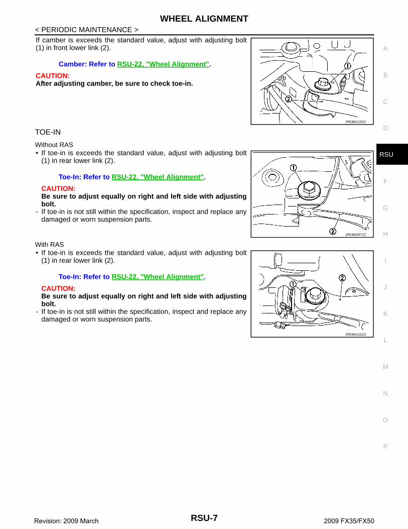
If camber is exceeds the standard value, adjust with adjusting bolt(1) in front lower link (2).
CAUTION:After adjusting camber, be sure to check toe-in.
TOE-IN
Without RAS• If toe-in is exceeds the standard value, adjust with adjusting bolt
(1) in rear lower link (2).
CAUTION:Be sure to adjust equally on right and left side with adjustingbolt.
- If toe-in is not still within the specification, inspect and replace anydamaged or worn suspension parts.
With RAS• If toe-in is exceeds the standard value, adjust with adjusting bolt
(1) in rear lower link (2).
CAUTION:Be sure to adjust equally on right and left side with adjustingbolt.
- If toe-in is not still within the specification, inspect and replace anydamaged or worn suspension parts.
Camber: Refer to RSU-22, "Wheel Alignment".
JPEIB0119ZZ
Toe-In: Refer to RSU-22, "Wheel Alignment".
JPEIB0097ZZ
Toe-In: Refer to RSU-22, "Wheel Alignment".
JPEIB0120ZZ
RSU-7Revision: 2009 March 2009 FX35/FX50

REAR LOWER LINK & COIL SPRING
< REMOVAL AND INSTALLATION >REMOVAL AND INSTALLATIONREAR LOWER LINK & COIL SPRING
Exploded View INFOID:0000000003858864
WITHOUT RAS
WITH RAS
1. Upper seat 2. Coil spring 3. Rubber seat
4. Rear lower link 5. Adjusting bolt 6. Front lower link
7. Rear suspension member
Refer to GI-4, "Components" for symbols in the figure.
JPEIB0114GB
1. Upper seat 2. Coil spring 3. Rubber seat
4. Rear lower link 5. Adjusting bolt 6. Front lower link
7. Rear suspension member
Refer to GI-4, "Components" for symbols in the figure.
JPEIB0121GB
RSU-8Revision: 2009 March 2009 FX35/FX50

REAR LOWER LINK & COIL SPRING
C
D
F
G
H
I
J
K
L
M
A
B
SU
N
O
P
< REMOVAL AND INSTALLATION >
R
Removal and Installation INFOID:0000000003858865
REMOVAL1. Remove tires with power tool.2. Set suitable jack under rear lower link to relieve the coil spring tension.3. Loosen rear lower link mounting nuts [rear suspension member side (without RAS) or RAS actuator
assembly (with RAS), and remove rear lower link mounting bolts and nuts (axle housing side) with powertool.
4. Slowly lower jack, then remove upper seat, coil spring and rubber sheet from rear lower link.5. Remove rear lower link mounting nuts and adjusting bolts [rear suspension member side (without RAS) or
RAS actuator assembly (with RAS) and remove rear lower link.
INSTALLATIONNote the following, and install in the reverse order of removal.• Match up rubber seat indentions and rear lower link grooves and attach.• Install coil spring by aligning the lower end of the large diameter
side to the step (A) between the rubber seat (1) and the rear lowerlink (2).CAUTION:Make sure spring is not up side down.
• Perform the final tightening of rear suspension member and axlehousing rubber bushing position under unladen condition with tireson level ground.
Inspection INFOID:0000000003858866
INSPECTION AFTER REMOVALCheck rear lower link, bushing and coil spring for deformation, crack, and damage. Replace it if necessary.
INSPECTION AFTER INSTALLATION1. Check wheel alignment. Refer to RSU-6, "Inspection".2. Adjust neutral position of steering angle sensor. Refer to BRC-9, "ADJUSTMENT OF STEERING ANGLE
SENSOR NEUTRAL POSITION : Special Repair Requirement".
JPEIB0098ZZ
RSU-9Revision: 2009 March 2009 FX35/FX50

REAR SHOCK ABSORBER
< REMOVAL AND INSTALLATION >REAR SHOCK ABSORBER
Exploded View INFOID:0000000003858867
WITHOUT CONTINUOUS DAMPING CONTROL
WITH CONTINUOUS DAMPING CONTROL
Removal and Installation INFOID:0000000003858868
REMOVAL1. Remove tires with power tool.2. Remove shock absorber actuator harness connector (with Continuous Damping Control).
1. Cap 2. Mounting seal 3. Shock absorber mounting bracket
4. Bound bumper cover 5. Shock absorber 6. Front lower link
Refer to GI-4, "Components" for symbols in the figure.
JPEIB0115GB
1. Cap 2. Mounting seal 3. Shock absorber mounting bracket
4. Bound bumper cover 5. Shock absorber 6. Front lower link
Refer to GI-4, "Components" for symbols in the figure.
JPEIB0130GB
RSU-10Revision: 2009 March 2009 FX35/FX50

REAR SHOCK ABSORBER
C
D
F
G
H
I
J
K
L
M
A
B
SU
N
O
P
< REMOVAL AND INSTALLATION >
R
3. Set suitable jack under axle assembly to relieve the coil spring tension.4. Remove shock absorber (lower side) with power tool.5. Gradually lower the jack to remove it from rear lower link.6. Remove shock absorber assembly mounting nuts (upper side)
( ), and then remove shock absorber assembly.
INSTALLATIONNote the following, and install in the reverse order of removal.• Perform final tightening of bolts and nuts at the shock absorber lower side (rubber bushing), under unladen
conditions with tires on level ground.
Disassembly and Assembly INFOID:0000000003858869
DISASSEMBLYCAUTION:Never damage shock absorber piston rod when removing components from shock absorber. 1. Remove cap from mounting bracket 2. Wrap a shop cloth around lower side of shock absorber and fix it with a vise.
CAUTION:Never set the cylindrical part of shock absorber with a vise.
3. Secure the piston rod tip so that piston rod does not turn, and remove piston rod lock nut.4. Remove mounting seal, mounting bracket and bound bumper cover from shock absorber.
ASSEMBLYInstall in the reverse order of disassembly.
Inspection INFOID:0000000003858870
INSPECTION AFTER REMOVALCheck the following items, and replace the parts if necessary.• Shock absorber assembly for deformation, cracks, damage.• Welded and sealed areas for oil leakage.
INSPECTION AFTER INSTALLATION1. Check shock absorber actuator harness connector for proper connection (with Continuous Damping Con-
trol).2. Check wheel alignment. Refer to RSU-6, "Inspection".3. Adjust neutral position of steering angle sensor. Refer to BRC-9, "ADJUSTMENT OF STEERING ANGLE
SENSOR NEUTRAL POSITION : Special Repair Requirement".
INSPECTION AFTER DISASSEMBLY
Bound Bumper and BushingCheck bound bumper cover and bushing for cracks and damage. Replace it if necessary.
Shock AbsorberCheck the following items, and replace the part if necessary.• Shock absorber for deformation, cracks, and other damage.• Piston rod for damage, uneven wear, and distortion.
INSPECTION AFTER ASSEMBLY
JPEIB0100ZZ
RSU-11Revision: 2009 March 2009 FX35/FX50

REAR SHOCK ABSORBER
< REMOVAL AND INSTALLATION >Make sure piston rod on shock absorber is not damaged when attaching components to shock absorber.Disposal INFOID:0000000005153126
1. Set shock absorber horizontally with the piston rod fully extended.
2. Drill 2 – 3 mm (0.08 – 0.12 in) hole at the position ( ) from topas shown in the figure to release gas gradually.CAUTION:• Wear eye protection (safety glasses).• Wear gloves.• Be careful with metal chips or oil blown out by the com-
pressed gas.NOTE:• Drill vertically in this direction ( ).• Directly to the outer tube avoiding brackets.• The gas is clear, colorless, odorless, and harmless.
3. Position the drilled hole downward and drain oil by moving the piston rod several times.CAUTION:Dispose of drained oil according to the law and local regulations.
A : 20 – 30 mm (0.79 – 1.18 in)
JPEIA0161ZZ
RSU-12Revision: 2009 March 2009 FX35/FX50
SUSPENSION ARM
C
D
F
G
H
I
J
K
L
M
A
B
SU
N
O
P
< REMOVAL AND INSTALLATION >
R
SUSPENSION ARM
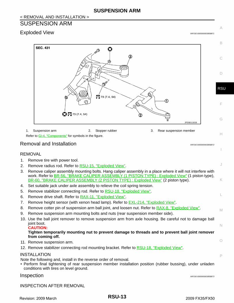
Exploded View INFOID:0000000003858871
Removal and Installation INFOID:0000000003858872
REMOVAL1. Remove tire with power tool.2. Remove radius rod. Refer to RSU-15, "Exploded View".3. Remove caliper assembly mounting bolts. Hang caliper assembly in a place where it will not interfere with
work. Refer to BR-56, "BRAKE CALIPER ASSEMBLY (1 PISTON TYPE) : Exploded View" (1 piston type),BR-60, "BRAKE CALIPER ASSEMBLY (2 PISTON TYPE) : Exploded View" (2 piston type).
4. Set suitable jack under axle assembly to relieve the coil spring tension.5. Remove stabilizer connecting rod. Refer to RSU-18, "Exploded View".6. Remove drive shaft. Refer to RAX-11, "Exploded View".7. Remove height sensor (with xenon head lamp). Refer to EXL-214, "Exploded View".8. Remove cotter pin of suspension arm ball joint, and loosen nut. Refer to RAX-8, "Exploded View".9. Remove suspension arm mounting bolts and nuts (rear suspension member side).10. Use the ball joint remover to remove suspension arm from axle housing. Be careful not to damage ball
joint boot.CAUTION:Tighten temporarily mounting nut to prevent damage to threads and to prevent ball joint removerfrom coming off.
11. Remove suspension arm.12. Remove stabilizer connecting rod mounting bracket. Refer to RSU-18, "Exploded View".
INSTALLATIONNote the following and, install in the reverse order of removal.• Perform final tightening of rear suspension member installation position (rubber bussing), under unladen
conditions with tires on level ground.
Inspection INFOID:0000000003858873
INSPECTION AFTER REMOVAL
1. Suspension arm 2. Stopper rubber 3. Rear suspension member
Refer to GI-4, "Components" for symbols in the figure.
JPEIB0116GB
RSU-13Revision: 2009 March 2009 FX35/FX50
SUSPENSION ARM
< REMOVAL AND INSTALLATION >AppearanceCheck the following items, and replace the part if necessary.• Suspension arm and bushing for deformation, cracks or damage.• Boot of ball joint for cracks or damage, and also for grease leakage.Ball Joint InspectionManually move ball stud at least ten times by hand to check for smooth movement.
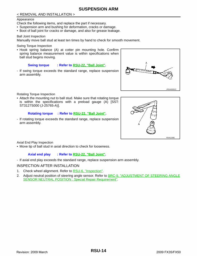
Swing Torque Inspection• Hook spring balance (A) at cotter pin mounting hole. Confirm
spring balance measurement value is within specifications whenball stud begins moving.
- If swing torque exceeds the standard range, replace suspensionarm assembly.
Rotating Torque Inspection• Attach the mounting nut to ball stud. Make sure that rotating torque
is within the specifications with a preload gauge (A) [SST:ST3127S000 (J-25765-A)].
- If rotating torque exceeds the standard range, replace suspensionarm assembly.
Axial End Play Inspection• Move tip of ball stud in axial direction to check for looseness.
- If axial end play exceeds the standard range, replace suspension arm assembly.
INSPECTION AFTER INSTALLATION1. Check wheel alignment. Refer to RSU-6, "Inspection".2. Adjust neutral position of steering angle sensor. Refer to BRC-9, "ADJUSTMENT OF STEERING ANGLE
SENSOR NEUTRAL POSITION : Special Repair Requirement".
Swing torque : Refer to RSU-22, "Ball Joint".
JPEIA0005ZZ
Rotating torque : Refer to RSU-22, "Ball Joint".
PDIA1258E
Axial end play : Refer to RSU-22, "Ball Joint".
RSU-14Revision: 2009 March 2009 FX35/FX50

RADIUS ROD
C
D
F
G
H
I
J
K
L
M
A
B
SU
N
O
P
< REMOVAL AND INSTALLATION >
R
RADIUS ROD
Exploded View INFOID:0000000003858874
Removal and Installation INFOID:0000000003858875
REMOVAL1. Remove tire with power tool.2. Remove radius rod mounting bolt and nut (axle housing side) with power tool.3. Remove radius rod mounting bolt (rear suspension member side) with power tool, and remove radius rod.
INSTALLATIONNote the following, and install in the reverse order of removal.• Perform final tightening of rear suspension member and axle installation position (rubber bushing), under
unladen conditions with tires on level ground.
Inspection INFOID:0000000003858876
INSPECTION AFTER REMOVALCheck radius rod and bushing for any deformation, cracks, or damage. Replace it if necessary.
INSPECTION AFTER INSTALLATION1. Check wheel alignment. Refer to RSU-6, "Inspection".2. Adjust neutral position of steering angle sensor. Refer to BRC-9, "ADJUSTMENT OF STEERING ANGLE
SENSOR NEUTRAL POSITION : Special Repair Requirement".
1. Rear suspension member 2. Radius rod
Refer to GI-4, "Components" for symbols in the figure.
JPEIB0092GB
RSU-15Revision: 2009 March 2009 FX35/FX50

FRONT LOWER LINK
< REMOVAL AND INSTALLATION >FRONT LOWER LINK
Exploded View INFOID:0000000003888725
WITHOUT RAS
WITH RAS
Removal and Installation INFOID:0000000003858878
REMOVAL
1. Upper seat 2. Coil spring 3. Rubber seat
4. Rear lower link 5. Adjusting bolt 6. Front lower link
7. Rear suspension member
Refer to GI-4, "Components" for symbols in the figure.
JPEIB0114GB
1. Upper seat 2. Coil spring 3. Rubber seat
4. Rear lower link 5. Adjusting bolt 6. Front lower link
7. Rear suspension member
Refer to GI-4, "Components" for symbols in the figure.
JPEIB0121GB
RSU-16Revision: 2009 March 2009 FX35/FX50

FRONT LOWER LINK
C
D
F
G
H
I
J
K
L
M
A
B
SU
N
O
P
< REMOVAL AND INSTALLATION >
R
1. Remove tire with power tool.2. Set suitable jack under axle assembly to relieve the coil spring tension.3. Remove shock absorber mounting bolts from front lower link. Refer to RSU-10, "Exploded View".4. Remove front lower link mounting bolts and nuts from axle housing with power tool.5. Remove stabilizer clamp and stabilizer bushing. Refer to RSU-18, "Exploded View".6. Remove front lower link mounting bolts and nuts from rear suspension member with power tool, and
remove front lower link.
INSTALLATIONNote the following, and install in the reverse order of removal.• Perform final tightening of rear suspension member and axle installation position (rubber bushing), under
unladen conditions with tires on level ground.
Inspection INFOID:0000000003858879
INSPECTION AFTER REMOVALCheck front lower link and bushing for any deformation, cracks, or damage. Replace it if necessary.
INSPECTION AFTER INSTALLATION1. Check wheel alignment. Refer to RSU-6, "Inspection".2. Adjust neutral position of steering angle sensor. Refer to BRC-9, "ADJUSTMENT OF STEERING ANGLE
SENSOR NEUTRAL POSITION : Special Repair Requirement".
RSU-17Revision: 2009 March 2009 FX35/FX50
REAR STABILIZER
< REMOVAL AND INSTALLATION >REAR STABILIZER
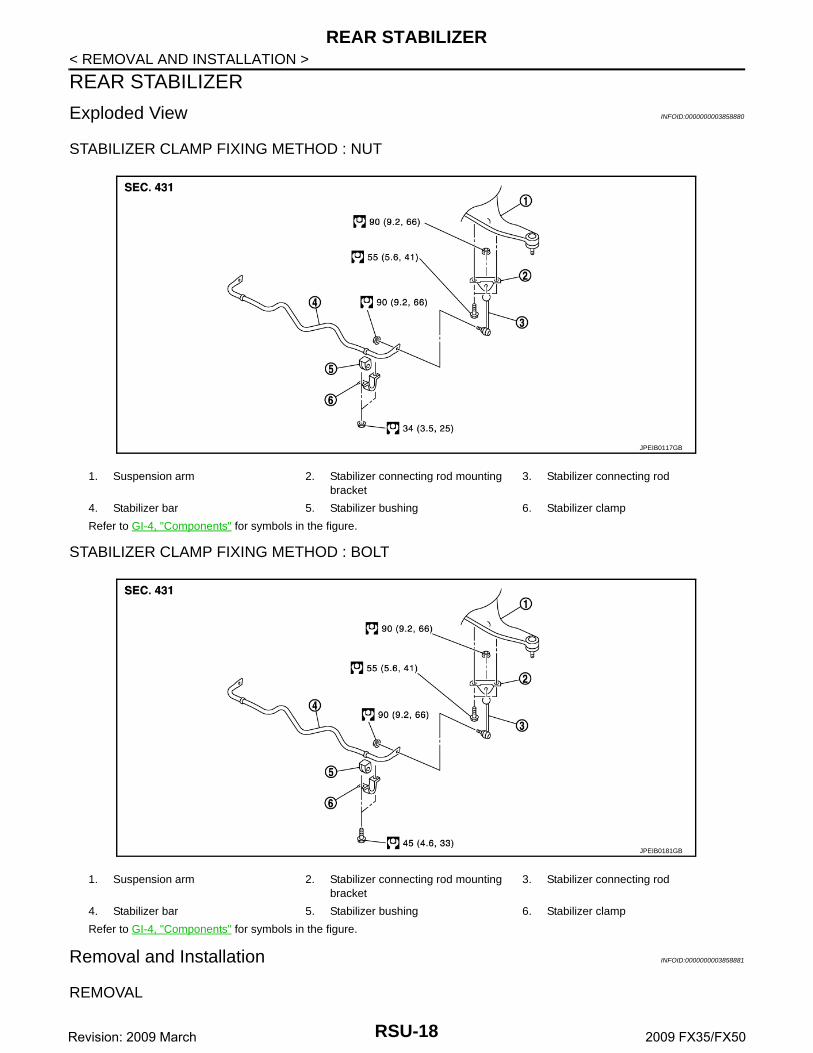
Exploded View INFOID:0000000003858880
STABILIZER CLAMP FIXING METHOD : NUT
STABILIZER CLAMP FIXING METHOD : BOLT
Removal and Installation INFOID:0000000003858881
REMOVAL
1. Suspension arm 2. Stabilizer connecting rod mounting bracket
3. Stabilizer connecting rod
4. Stabilizer bar 5. Stabilizer bushing 6. Stabilizer clamp
Refer to GI-4, "Components" for symbols in the figure.
JPEIB0117GB
1. Suspension arm 2. Stabilizer connecting rod mounting bracket
3. Stabilizer connecting rod
4. Stabilizer bar 5. Stabilizer bushing 6. Stabilizer clamp
Refer to GI-4, "Components" for symbols in the figure.
JPEIB0181GB
RSU-18Revision: 2009 March 2009 FX35/FX50

REAR STABILIZER
C
D
F
G
H
I
J
K
L
M
A
B
SU
N
O
P
< REMOVAL AND INSTALLATION >
R
1. Remove center muffler. Refer to EX-5, "Exploded View" (VQ35HR), EX-10, "Exploded View" (VK50VE).2. Remove under cover.3. Remove stabilizer connecting rod mounting nuts (lower side) with power tool, and remove stabilizer con-
necting rod from stabilizer bar.4. Remove stabilizer connecting rod mounting nuts (upper side) with power tool, and remove stabilizer con-
necting rod from stabilizer connecting rod mounting bracket.5. Remove mounting bolts or nuts on stabilizer clamp with power tool, and remove stabilizer bar.6. Remove stabilizer connecting rod mounting bracket.
INSTALLATIONNote the following, and install in the reverse order of removal.• Tighten the mounting nut to the specified torque while holding a hexagonal part of stabilizer connecting rod
side.
Inspection INFOID:0000000003858882
INSPECTION AFTER REMOVALCheck stabilizer bar, stabilizer connecting rod, stabilizer bushing and stabilizer clamp for deformation, cracksor damage. Replace it if necessary.
RSU-19Revision: 2009 March 2009 FX35/FX50

REAR SUSPENSION MEMBER
< UNIT REMOVAL AND INSTALLATION >UNIT REMOVAL AND INSTALLATIONREAR SUSPENSION MEMBER
Exploded View INFOID:0000000003858883
Removal and Installation INFOID:0000000003858884
REMOVAL1. Remove tires with power tool.2. Remove center muffler. Refer to EX-5, "Exploded View" (VQ35HR), EX-10, "Exploded View" (VK50VE).3. Remove radius rod. Refer to RSU-15, "Exploded View".4. Remove caliper assembly. Hang caliper assembly in a place where it will not interfere with work. Refer to
BR-56, "BRAKE CALIPER ASSEMBLY (1 PISTON TYPE) : Exploded View" 1 piston type), BR-60,"BRAKE CALIPER ASSEMBLY (2 PISTON TYPE) : Exploded View" (2 piston type).CAUTION:Avoid depressing brake pedal while brake caliper is removed.
5. Remove disc rotor. Refer to BR-57, "BRAKE CALIPER ASSEMBLY (1 PISTON TYPE) : Removal andInstallation" (1 piston type), BR-61, "BRAKE CALIPER ASSEMBLY (2 PISTON TYPE) : Removal andInstallation" (2 piston type).
6. Remove wheel sensor harness from rear suspension member. Refer to BRC-134, "REAR WHEEL SEN-SOR : Exploded View".
7. Remove height sensor harness from rear suspension member (with xenon head lamp). Refer to EXL-214,"Exploded View".
8. Remove shock absorber actuator harness connector (with Continuous Damping Control).9. Remove stabilizer bar. Refer to RSU-18, "Exploded View".10. Remove drive shaft. Refer to RAX-11, "Exploded View".11. Remove propeller shaft. Refer to DLN-116, "Exploded View" (3S80AR), DLN-124, "Exploded View"
(3F80AR-1VL107), DLN-132, "Exploded View" (3F-R-2VL107).12. Remove final drive. Refer to DLN-207, "2WD : Exploded View" [R200 (2WD)], DLN-208, "AWD : Exploded
View" [R200 (AWD)], DLN-271, "Exploded View" (R230).13. Remove parking brake cable mounting bolt and separate parking brake cable from vehicle and rear sus-
pension member. Refer to PB-5, "Exploded View".
1. Mount stopper 2. Rear suspension member 3. Rear suspension member stay
4. Tunnel stay 5. Pin stay
Refer to GI-4, "Components" for symbols in the figure.
JPEIB0118GB
RSU-20Revision: 2009 March 2009 FX35/FX50

REAR SUSPENSION MEMBER
C
D
F
G
H
I
J
K
L
M
A
B
SU
N
O
P
< UNIT REMOVAL AND INSTALLATION >
R
14. Remove shock absorber mounting bolts (lower side). Refer to RSU-10, "Exploded View".15. Remove rear lower link and coil spring. Refer to RSU-8, "Exploded View". 16. Remove RAS actuator assembly (with RAS). Refer to STC-107, "Exploded View".17. Set suitable jack under rear suspension member.18. Remove pin stay.19. Remove rear suspension member stay.20. Slowly lower jack, then remove rear suspension member, suspension arm, front lower link, wheel hub and
housing from vehicle as a unit.21. Remove mounting bolts and nuts, then remove suspension arm, front lower link, wheel hub and housing
from rear suspension member. Refer to RSU-13, "Exploded View", RSU-16, "Exploded View", RAX-8,"Exploded View"
INSTALLATIONNote the following, and install in the reverse order of the removal.• Perform the final tightening of each of parts under unladen conditions, which were removed when removing
rear suspension assembly.• Check wheel sensor harness for proper connection. Refer to BRC-134, "REAR WHEEL SENSOR :
Exploded View". • Never reuse cotter pin.
Inspection INFOID:0000000003858885
INSPECTION AFTER REMOVALCheck rear suspension member for deformation, cracks, or any other damage. Replace if necessary.
INSPECTION AFTER INSTALLATION1. Check shock absorber actuator harness connector for proper connection (with Continuous Damping Con-
trol).2. Adjust parking brake operation (stroke). Refer to PB-3, "Inspection and Adjustment".3. Check wheel alignment. Refer to RSU-6, "Inspection".4. Adjust neutral position of steering angle sensor. Refer to BRC-9, "ADJUSTMENT OF STEERING ANGLE
SENSOR NEUTRAL POSITION : Special Repair Requirement".
RSU-21Revision: 2009 March 2009 FX35/FX50

SERVICE DATA AND SPECIFICATIONS (SDS)
< SERVICE DATA AND SPECIFICATIONS (SDS)SERVICE DATA AND SPECIFICATIONS (SDS)SERVICE DATA AND SPECIFICATIONS (SDS)
Wheel Alignment INFOID:0000000003858886
Measure value under unladen* conditions.
*: Fuel, engine coolant and lubricant are full. Spare tire, jack, hand tools and mats are in designated positions.
Ball Joint INFOID:0000000003858887
Wheel Height INFOID:0000000003858888
Measure value under unladen* conditions.
*: Fuel, engine coolant and lubricant are full. Spare tire, jack, hand tools and mats are in designated positions.
Item Standard
Tire size 265/60R18 265/50R20 265/45R21
CamberDegree minute (Decimal degree)
Minimum –1° 40′ (–1.66°)
Nominal –1° 10′ (–1.16°)
Maximum –0° 40′ (–0.67°)
Toe-in
Total toe-inDistance
Minimum 0 mm (0 in)
Nominal In 3.2 mm (0.126 in) In 3.1 mm (0.122 in)
Maximum In 6.4 mm (0.252 in) In 6.2 mm (0.244 in)
Toe angle (left wheel or right wheel)Degree minute (Decimal degree)
Minimum 0° 00′ (0.00°)
Nominal In 0° 07′ (0.12°)
Maximum In 0° 14′ (0.23°)
Item Standard
Swing torque 0.5 – 3.4 N·m (0.06 – 0.34 kg-m, 5 – 30 in-lb)
Measurement on spring balance (cotter pinhole position) 8.1 – 54.8 N (0.83 – 5.59 kg, 1.83 – 12.31 lb)
Rotating torque 0.5 – 3.4 N·m (0.06 – 0.34 kg-m, 5 – 30 in-lb)
Axial end play 0 mm (0 in)
Applied model 2WD AWD
Tire 265/60R18 265/50R20 265/60R18 265/50R20 265/45R21
Rear (Hr) 831 mm (32.72 in) 830 mm (32.68 in) 831 mm (32.72 in)
SFA746B
RSU-22Revision: 2009 March 2009 FX35/FX50