Survey Manual - Mississippisp.mdot.ms.gov/RoadwayDesign/MDOT Survey Manual/2008 Survey M… ·...
130
2008 Mississippi Department of Transportation (MDOT) SURVEY MANUAL The purpose of this manual is to define the minimum specifications and procedures that shall be followed while performing surveys for MDOT by MDOT surveyors or contract consultant surveyors. It is also designed to provide uniformity in surveys preformed for MDOT.
Transcript of Survey Manual - Mississippisp.mdot.ms.gov/RoadwayDesign/MDOT Survey Manual/2008 Survey M… ·...

2008
Mississippi Department of Transportation (MDOT)
SURVEY MANUAL The purpose of this manual is to define the minimum specifications and procedures that shall be followed while performing surveys for MDOT by MDOT surveyors or contract consultant surveyors. It is also designed to provide uniformity in surveys preformed for MDOT.

Survey Manual 2008
Page 2 of 130
Date Printed: 06/11/2009
Table of Contents Table of Contents ................................................................................................................................................ 2
1.0 Document Objectives .................................................................................................................................. 10
1.1 MDOT’s Mission Statement .................................................................................................................... 10
1.2 Purpose of the Survey Manual ................................................................................................................ 10
2.0 Safety Information ...................................................................................................................................... 11
2.1 Safety Responsibilities for all Survey Operations ................................................................................... 11
2.1.1 Individual Responsibilities ................................................................................................................ 11
2.1.2 Personal Protective Equipment ....................................................................................................... 11
2.1.3 Party Chief Duties............................................................................................................................. 12
2.1.4 Field and Office Supervisor Duties ................................................................................................... 12
2.1.5 Safe Driving Practices ....................................................................................................................... 13
2.2 Construction Surveying Operations ........................................................................................................ 14
2.2.1 Surveying Near Traffic ...................................................................................................................... 14
2.2.2 Lookouts ........................................................................................................................................... 15
2.2.3 Flaggers ............................................................................................................................................ 15
2.2.4 Protective Vehicles ........................................................................................................................... 15
2.2.5 Amber and Strobe Warning Lights ................................................................................................... 16
2.2.6 Temporary Traffic Control ................................................................................................................ 16
2.2.7 Planning ............................................................................................................................................ 17
2.2.8 Surveying Without Traffic Controls .................................................................................................. 17
2.2.9 Special Operations – Night Operations ............................................................................................ 17
2.2.10 Special Operations – Railroads ...................................................................................................... 18
2.2.11 Special Operations – Water Operations ........................................................................................ 18
2.3 First Aid – General Information .............................................................................................................. 19
2.4 Work Area Hazards ................................................................................................................................. 19
2.4.1 Environmental Hazards – Animal and Insects .................................................................................. 19
2.4.2 Environmental Hazards – Poison Oak, Poison Ivy and Other Plants ................................................ 20
2.4.3 Environmental Hazards – Sunstroke & Heatstroke ......................................................................... 21

Survey Manual 2008
Page 3 of 130
Date Printed: 06/11/2009
2.4.4 Environmental Hazards – Cold Weather & Hypothermia ................................................................ 22
2.4.5 Other Hazards – Power Lines ........................................................................................................... 22
2.4.6 Other Hazards – Radio Transmitters ................................................................................................ 23
2.4.7 Other Hazards – Pressurized Spray Cans ......................................................................................... 23
2.4.8 Other Hazards – Hazardous Material Spills...................................................................................... 23
2.4.9 Other Hazards – Lead Contaminated Soils ....................................................................................... 23
2.5 Hand Tool Safety ..................................................................................................................................... 24
2.5.1 General Hand Tool Safety Information ............................................................................................ 24
2.5.2 Picks ................................................................................................................................................. 24
2.5.3 Mauls and Sledge Hammers ............................................................................................................ 24
2.5.4 Files .................................................................................................................................................. 24
2.5.5 Axes, Hatchets, Machetes & Brush Hooks (Kaiser Blades) ....................................................... 25
2.5.6 Brush and Tree Cutting Machete ..................................................................................................... 25
2.5.7 Axes .................................................................................................................................................. 25
2.5.8 Brush Hook (Kaiser Blade) ................................................................................................................ 26
2.6 References – Safety ................................................................................................................................. 26
3.0 Project Control ............................................................................................................................................ 27
3.1 Primary Horizontal Control ..................................................................................................................... 27
3.1.1 State Plane Coordinates ................................................................................................................... 27
3.1.2 Point Identification .......................................................................................................................... 31
3.1.3 Method / Equipment Required ........................................................................................................ 31
3.1.4 Project Planning and Execution ....................................................................................................... 31
3.1.5 GPS Observations ............................................................................................................................. 32
3.1.6 Field Procedures .............................................................................................................................. 32
3.1.7 Data Processing and Evaluation ....................................................................................................... 32
3.1.8 Programs Available for Aid in Converting to State Plane Coordinates ............................................ 34
3.1.9 Availability and Recovery of Existing Control .................................................................................. 34
3.2 Secondary Horizontal Control ................................................................................................................. 35
3.2.1 Point Identification .......................................................................................................................... 35
3.2.2 Equipment Required ........................................................................................................................ 35
3.2.3 Project Planning and Execution ....................................................................................................... 36

Survey Manual 2008
Page 4 of 130
Date Printed: 06/11/2009
3.2.4 GPS Observations ............................................................................................................................. 36
3.2.5 Data Processing and Evaluation ....................................................................................................... 36
3.2.6 Total Station Traverse ...................................................................................................................... 37
3.2.7 Data Collection ................................................................................................................................. 37
3.2.8 Data Processing and Evaluation ....................................................................................................... 37
3.3 Primary Vertical Control .......................................................................................................................... 37
3.3.1 Method / Equipment Required ........................................................................................................ 38
3.3.2 Data Processing and Evaluation ....................................................................................................... 38
3.3.3 Datum Ties ....................................................................................................................................... 38
3.3.4 Level Rods ........................................................................................................................................ 38
3.3.5 Turning Points .................................................................................................................................. 39
3.3.6 Digital Levels .................................................................................................................................... 39
3.3.7 Rodmen ............................................................................................................................................ 39
3.4 Secondary Vertical Control ..................................................................................................................... 40
3.4.1 Methods / Equipment Required ...................................................................................................... 40
3.4.2 Data Processing and Evaluation ....................................................................................................... 40
3.5 Location and Construction of New Monumentation .............................................................................. 40
3.5.1 Primary and Secondary Control ....................................................................................................... 40
3.5.2 Monument Types ............................................................................................................................. 40
3.6 Control Submittal .................................................................................................................................... 41
3.7 Illustrations ............................................................................................................................................. 42
3.7.1 Figure 1 – Mississippi State Plane Coordinate System Zones .......................................................... 42
3.7.2 Figure 2 – Relationship Between the Reference Ellipsoid, the Geoid and Orthometric Height ...... 43
3.7.3 Figure 3 – Sample NGS Data Sheet for Harn Point ........................................................................... 44
3.7.4 Figure 4 – Sample NGS Data Sheet for Benchmark ......................................................................... 48
3.7.5 Figure 5 – Convergence of Meridians .............................................................................................. 50
3.7.6 Figure 6 – Sample MDOT GPS Control Note .................................................................................... 51
3.8 References – Project Control .................................................................................................................. 51
4. 0 Preliminary Surveys .................................................................................................................................... 53
4.1 General Information ............................................................................................................................... 53
4.1.1 Introduction ..................................................................................................................................... 53

Survey Manual 2008
Page 5 of 130
Date Printed: 06/11/2009
4.1.2 Horizontal & Vertical Control ........................................................................................................... 53
4.1.3 Topographic Accuracy ...................................................................................................................... 53
4.1.4 Survey Notification ........................................................................................................................... 54
4.1.5 Statewide Flagging Color Scheme .................................................................................................... 56
4.2 Topographic Surveys (Methods) ............................................................................................................. 56
4.2.1 Horizontal & Vertical Combined (DTM Survey) ............................................................................... 56
4.2.2 Describing Shots in the Field ............................................................................................................ 59
4.2.3 Point Descriptions ............................................................................................................................ 60
4.2.4 Vertical Separate (Cross‐sections) ................................................................................................... 64
4.3 Highway Surveys (Deliverables) .............................................................................................................. 65
4.3.1 Vertical Data (Existing Ground) ........................................................................................................ 66
4.3.2 Horizontal (TOPO) ............................................................................................................................ 66
4.3.3 Elements of the TOPO.DGN ............................................................................................................. 66
4.3.4 Bridge Specific .................................................................................................................................. 70
4.3.5 Drainage ........................................................................................................................................... 74
4.3.5.1 Hydraulic Information for the Bridge Division – Drainage Areas 1,000 Acres or Greater ............ 74
4.3.7 Hydraulic Information for the Roadway Design Division – Drainage Areas from 200‐1,000 Acres . 76
4.3.8 Hydraulic Information for the Roadway Design Division – Drainage areas less than 200 acres ..... 77
4.3.9 Property Data and Existing Right‐of‐Way ........................................................................................ 77
4.4 Site Surveys (Deliverables) for ASU ......................................................................................................... 77
4.5 Preliminary Plans..................................................................................................................................... 78
4.6 Example Survey ....................................................................................................................................... 79
4.7 References – Preliminary Surveys ........................................................................................................... 83
5.0 Photogrammetric Surveys ........................................................................................................................... 84
5.1 Introduction ............................................................................................................................................ 84
5.2 Flight Requirements ................................................................................................................................ 84
5.2.1 Flight Lines ....................................................................................................................................... 85
5.2.2 Flying Height .................................................................................................................................... 85
5.2.3 Scale of Vertical Photography .......................................................................................................... 86
5.2.4 Flight Conditions .............................................................................................................................. 86
5.2.5 Equipment ........................................................................................................................................ 86

Survey Manual 2008
Page 6 of 130
Date Printed: 06/11/2009
5.2.6 Imagery ............................................................................................................................................ 87
5.3 Photogrammetric Control ....................................................................................................................... 87
5.3.1 Photogrammetric Control Survey .................................................................................................... 87
5.3.2 Coordinate System / Datum............................................................................................................. 89
5.3.3 Metadata .......................................................................................................................................... 89
5.4 Project Quality Control ........................................................................................................................... 90
5.4.1 Photogrammetric Compilation ........................................................................................................ 90
5.5 Photogrammetric Products ..................................................................................................................... 90
5.5.1 Planimetric Mapping ........................................................................................................................ 90
5.5.2 Digital Terrain Models ...................................................................................................................... 92
5.5.3 Image Products ................................................................................................................................ 94
5.5.4 Data Media ....................................................................................................................................... 94
5.6 LiDAR ....................................................................................................................................................... 95
5.6.1 Capabilities and Limitations ............................................................................................................. 95
5.6.2 Comparisons with Existing Technologies ......................................................................................... 95
5.6.3 Potential Use for MDOT ................................................................................................................... 96
5.7 References – Photogrammetric Surveys ................................................................................................. 96
6.0 Right‐of‐Way and Property Surveys ............................................................................................................ 98
6.1 Responsible Person in Charge of Boundary Surveys ............................................................................... 98
6.2 Accuracy Standards for Boundary Surveys ............................................................................................. 98
6.3 Property Map Survey .............................................................................................................................. 98
6.3.1 Property Record Research ............................................................................................................... 99
6.3.2 Property Field Survey ....................................................................................................................... 99
6.3.3 Property Map Preparation and Submittal ....................................................................................... 99
6.4 Right‐of‐Way Acquisition Maps ............................................................................................................ 101
6.4.1 Deeds ............................................................................................................................................. 101
6.4.2 X Property ...................................................................................................................................... 102
6.4.3 Eminent Domain ............................................................................................................................ 102
6.5 Standards for Preparing As‐Built Right of Way Plats ............................................................................ 104
6.5.1 Method 1: Project Not Originally Surveyed in MSPCS ................................................................... 104
6.5.2 Method 2: Project Originally Surveyed in MSPC ............................................................................ 108

Survey Manual 2008
Page 7 of 130
Date Printed: 06/11/2009
6.6 SPECIAL PROVISION NO. 907‐617‐1 CODE: (IS) ..................................................................................... 114
6.6.1 ‐‐ 907‐617.01 Description .............................................................................................................. 114
6.6.2 ‐‐ 907‐617.02 Materials.................................................................................................................. 114
6.6.3 ‐‐ 907‐617.03 Construction Requirements .................................................................................... 114
7.0 Surveying Equipment (Conventional and GPS) ......................................................................................... 117
7.1 Overview ............................................................................................................................................... 117
7.2 Care and Maintenance .......................................................................................................................... 117
7.2.1 General ........................................................................................................................................... 117
7.2.2 Routine Care of Surveying Instruments ......................................................................................... 118
7.3 Transportation ...................................................................................................................................... 118
7.3.1 Vehicular Transport........................................................................................................................ 118
7.3.2 Casing and Uncasing ...................................................................................................................... 118
7.3.3 Field Transport of Surveying Instruments ...................................................................................... 119
7.3.4 Care During Instrument Setups ...................................................................................................... 119
7.4 Adjustments of Surveying Instruments ................................................................................................. 119
7.4.1 Field Adjustments .......................................................................................................................... 119
7.4.2 Major Adjustments ........................................................................................................................ 119
7.4.3 Care of Tools .................................................................................................................................. 120
7.5 Angular Measurement Instruments ...................................................................................................... 120
7.5.1 General ........................................................................................................................................... 120
7.5.2 Care of Total Stations ..................................................................................................................... 120
7.6 Distance Measurement Instruments .................................................................................................... 120
7.6.1 General ........................................................................................................................................... 120
7.6.2 GPS Equipment .............................................................................................................................. 121
7.6.3 Specifications ................................................................................................................................. 121
7.6.4 Suggested Inventory for Typical GPS Survey Crews ....................................................................... 121
7.6.5 Care of GPS Equipment .................................................................................................................. 121
7.6.6 Total Stations and EDM’s ............................................................................................................... 122
7.6.7 Specifications ................................................................................................................................. 122
7.6.8 Care of EDM’s ................................................................................................................................. 122
7.6.9 Tapes .............................................................................................................................................. 123

Survey Manual 2008
Page 8 of 130
Date Printed: 06/11/2009
7.6.10 Care of Tapes ............................................................................................................................... 123
7.7 Accessories for Angular and Distance Measurement Instruments....................................................... 123
7.7.1 Tribrachs ........................................................................................................................................ 123
7.7.2 Use of Tribrachs ............................................................................................................................. 123
7.7.3 Care of Tribrachs ............................................................................................................................ 123
7.7.4 Adjustments of Tribrachs ............................................................................................................... 124
7.7.5 Tripods ........................................................................................................................................... 124
7.7.6 Care of Tripods ............................................................................................................................... 124
7.7.7 Sighting Equipment ........................................................................................................................ 125
7.7.8 Plumb Bob ...................................................................................................................................... 125
7.7.9 Range Poles .................................................................................................................................... 125
7.7.10 Forced Centering Targets ............................................................................................................. 125
7.7.11 EDM Prisms .................................................................................................................................. 125
7.7.12 Care of Sighting Equipment ......................................................................................................... 125
7.8 Leveling Instruments ............................................................................................................................. 126
7.8.1 Hand Levels .................................................................................................................................... 126
7.8.2 Automatic Levels ............................................................................................................................ 126
7.8.3 Digital Levels .................................................................................................................................. 126
7.8.4 Field Operations ............................................................................................................................. 126
7.8.5 Horizontal Cross‐Hair Test and Adjustment (Two‐Peg Test) ......................................................... 127
7.8.6 Data Collection, Storage, and Transfer .......................................................................................... 127
7.8.7 Routine Maintenance and Care ..................................................................................................... 127
7.8.8 Transport and Storage ................................................................................................................... 127
7.8.9 Care of Levels ................................................................................................................................. 127
7.8.10 Leveling Rods ............................................................................................................................... 128
7.8.11 Care of Leveling Rods ................................................................................................................... 128
7.8.12 Bull's Eye Rod and Pole Levels ..................................................................................................... 129
7.8.13 Adjustment ................................................................................................................................... 129
7.9 Miscellaneous Accessories .................................................................................................................... 129
7.9.1 Hand Held Radios ........................................................................................................................... 129
7.9.2 Care and Use of Radios .................................................................................................................. 129

Survey Manual 2008
Page 9 of 130
Date Printed: 06/11/2009
7.9.3 Batteries ......................................................................................................................................... 129
7.9.4 Data ................................................................................................................................................ 130
7.9.5 Remarks ......................................................................................................................................... 130

Survey Manual 2008
Page 10 of 130
Date Printed: 06/11/2009
1.0 Document Objectives
1.1 MDOT’s Mission Statement The Mississippi Department of Transportation is responsible for providing a safe intermodal transportation network that is planned, designed, constructed and maintained in an effective, cost efficient, and environmentally sensitive manner.
1.2 Purpose and Authority This manual was designed as a replacement to the 1998 MDOT Survey Manual due to changing surveying technology and the needs of MDOT. The principal purpose of this manual is to secure an optimum degree of statewide uniformity in surveying procedures, to establish and maintain survey standards, and to improve the overall efficiency of the Department’s survey function. The manual was created by an active committee comprised of representatives from each District, Roadway Design, Bridge, Right of Way, Contract Administration, and Construction divisions.
A legal standard for surveys is not established or intended by this manual.
The Manual does not establish any legal or administrative interpretations of the Department’s contracts. In the case of a conflict between the requirements of this manual and the requirements of the contract documents, the contract document shall take precedence.
APPROVED FOR DISTRIBUTION

Survey Manual 2008
Page 11 of 130
Date Printed: 06/11/2009
2.0 Safety Information Most people who have ever experienced an accident tend to have one thing in common – they believed it could not happen to them. A meaningful safety program requires that each MDOT survey employee clearly acknowledge that
“IT CAN HAPPEN TO ME.”
Therefore each person must ask “What is my responsibility?” And “What can I do to lessen my chances of being in an accident?”
This chapter provides a compact source of the basic specifications and responsibilities for safety and health that will aid in preventing accidents and personal injuries while performing field surveying by MDOT or contractor or consultant surveyors. It was compiled from various safety publications distributed by federal, state, and private agencies or firms.
All traffic controls shall comply with the “Manual on Uniform Traffic Control Devices”.
2.1 Safety Responsibilities for all Survey Operations Only you can be primarily responsible for your own safety. Hopefully through your attentiveness to recognize and report unsafe conditions, and through the use of this manual and other manuals referenced herein, you may safely complete your surveys.
2.1.1 Individual Responsibilities • Employees, first and foremost, are responsible for their own personal safety. • Employees need to be alert for possible unsafe conditions and/or unsafe acts, and should report
unsafe conditions and/or acts to the supervisor or acting party chief, in charge. • Employees shall promptly report all incidents, accidents, and personal injuries to their supervisor
after rendering or finding aid for injured persons. • Employees who fail to comply with safety and health policies, procedures, regulations, laws, or rules
shall be subject to disciplinary action in accordance with the provisions described in the Mississippi State Employee Handbook.
• Employees must report for work properly dressed to protect themselves from exposure to conditions found on the work site. Garments that expose upper body parts (midriff and shoulders) and bare legs are prohibited. Employees shall wear appropriate footwear for the assigned task and work area.
2.1.2 Personal Protective Equipment Every survey employee will use/wear personal protective equipment at all times while on the job. The following list identifies types of Personal Protective Equipment that should be used while performing field surveying.
• Hard Hat – Employees must wear hard hats during any work activity that may expose them to a head injury.
• Soft Hat • Safety Vest – An MDOT approved safety vest shall be worn whenever working within any highway
right of way or on a construction site.

Survey Manual 2008
Page 12 of 130
Date Printed: 06/11/2009
• Safety Glasses – clear • Goggles – clear or amber • Leather Gloves • Respirators • Dust Mask • Ear Protection – muff or plug • Protective Clothing • Foot Protection • Personal Floatation Devices • Fall Protection
2.1.3 Party Chief Duties The Party Chief should ensure that all safety rules and procedures are followed and that all work is performed safely. The Party Chief must ensure the use of the safest possible method for each operation. This responsibility may not be delegated. Duties of the Party Chief include:
• Make safety the first priority in planning each survey. • Before starting work, inspect all traffic controls for conformance to MDOT standards as stated in the
Manual on Uniform Traffic Control Devices and continue to monitor conditions to ensure that controls are adequate for any change in conditions.
• Cease work and notify the field supervisor immediately if any field conditions become unsafe. • Train and provide lookouts whenever necessary. • Provide flaggers whenever necessary that have completed the flagger training course. • Utilize protective vehicles whenever appropriate. • Avoid assigning party members to independent tasks in high‐hazard areas that isolate them from
other party personnel. Try to have each member working with a buddy. This is especially important in high‐hazard areas, such as along roads, and in remote woodland and swampy areas.
• Ensure that each employee possesses the required personal protective equipment and understands its proper use.
• Train new employees to safely perform required work tasks before assigning them to work. • Ensure that tools are used and stored safely. • Do not allow employees to work if they refuse to work safely. Refer the matter to your supervisor. • Report all violent acts, threats of physical violence, verbal abuse, property damage, security hazards,
and other inappropriate activities to the supervisor. • Report and document all occupational injuries and illnesses.
2.1.4 Field and Office Supervisor Duties Field and office supervisors may be first or second line supervisors. Field supervisors generally supervise more than one field party. Supervisors are responsible for conducting MDOT business in the safest possible manner consistent with Departmental policies, procedures, and work practices, including:
• Ensuring that employees who fail to comply with safety and health policies, procedures, regulations, laws, or rules are disciplined in accordance with the provisions described in the Mississippi State Employee Handbook.
• Ensuring that all employees receive first aid and defensive driving training, as well as any required training for hazardous tasks such as operating a chainsaw.

Survey Manual 2008
Page 13 of 130
Date Printed: 06/11/2009
• Ensuring that all employees receive Safety Training for special circumstances including construction surveys on superstructures.
• Ensuring that employee safety and health issues are discussed and assessed annually at the time of issuing the “Individual Development Plan/Performance and Appraisal Summary” report and when employee probationary reports are issued.
• Scheduling staff meetings to disseminate information on accident prevention and on new safety policies and devises.
• Periodically inspecting field and office work sites to identify, document, and eliminate hazards that might cause injury or illness.
• Obtaining an approved traffic control plan, if necessary, and providing a copy to the party chief. • Approving all surveys to be conducted without traffic controls.
Supervisors are responsible to report and document occupational injuries and illnesses, and arrange for appropriate workers’ compensation benefits to employees who are injured or contract an illness arising out of their employment.
When assigning field crews to projects or sending office personal on field trips, consider: • The experience of personnel in undertaking hazardous tasks. • Possible health problems for specific employees (such as poison oak allergies). • Traffic hazards (plan for any controls that are needed). • Unusual hazards associated with the work. • Making the employee aware of facilities that are approved for treating industrial injuries. Inform the
employee that each office and survey party has a copy of the list. • Ensuring that each party chief assigned to the field is scheduled for first aid training as soon as
possible and at least once every three years thereafter according to recertification needs. • Describing hazards that are likely to be encountered in the employee’s first assignments and the
protective measures to be used. • Briefing the employee on:
– Medical care available throughout the State. – Accident and injury reporting procedures and their purposes. – The right to refuse to perform tasks that are dangerous or hazardous. – Responsibilities in case of personal and/or motor vehicle accidents.
Employees who fail to comply with safety and health policies, procedures, regulations, laws, or rules, shall be subject to disciplinary action in accordance with the provisions described in the Mississippi State Employee Handbook.
2.1.5 Safe Driving Practices Employees or contractor employees working for MDOT are not exempt from traffic laws. Employees operating vehicles and mobile equipment will obey all State and Local Traffic Laws and Departmental Policies, Rules and Regulations:
• The number of employees permitted to ride in a car, truck, or mobile equipment shall not exceed the seat space and seat belts as provided by the manufacturer.
• Safety seat belts installed in vehicles and mobile equipment shall be used by the operator and passengers while the vehicle or mobile equipment is in use. The operator shall not place the vehicle in motion until all occupants have properly secured their safety belts.

Survey Manual 2008
Page 14 of 130
Date Printed: 06/11/2009
• It is the operator’s responsibility to report all vehicle and equipment malfunctions and defective parts.
• The operator should always signal a turning movement or a lane change.
When it is necessary to stop a Department vehicle at locations where traffic does not normally stop, the employee shall give warning to following vehicles by flashing his brake lights and slowing down gradually.
Should disabled equipment, either State or privately owned, be parked on the pavement without proper protection, it is the duty of employees to protect traffic by placing fuses, reflectors or torches at the scene. In the case of privately‐owned vehicles, the matter should then be referred to the nearest police agency, as soon as possible.
2.2 Construction Surveying Operations Construction Surveys may be categorized by two different types, preliminary surveys and actual surveys during construction. Possibly the most dangerous may be the preliminary survey, as the crew will be working without the contractor’s established traffic control and safety plan. They may also be working in near traffic situations without extra personnel available to perform specific safety related tasks.
During the course of any survey work, observe the following safety guidelines: • Be extremely cautious around heavy and fast‐moving equipment or vehicles, especially on highways
or haul roads and around any equipment with limited driver visibility. • Do not rely on the operator’s visibility, judgment, or ability. Make eye contact with the operator
before walking in front of or behind any piece of equipment. • Use lookouts, flaggers, and temporary traffic control as conditions dictate. • Suspend survey operations when uncontrollable hazards develop. Resume work only when safe
working conditions have been restored.
2.2.1 Surveying Near Traffic • Face Traffic – Whenever feasible, each employee must face moving traffic at all times. If it is not
possible to face traffic, a lookout should be assigned to watch oncoming traffic. • Move Deliberately – Do not make sudden movements that might confuse a motorist and cause an
accident. • Signal Cautiously – Whenever feasible, use radio communication. Carefully and deliberately use
surveying hand signals so they will not startle or confuse motorists or be mistaken for a flagger’s direction.
• Avoid Interrupting Traffic Flow – Minimize crossing traffic lanes and never attempt to run across traffic lanes as you might fall or trip.
• Physical Barriers – Whenever feasible, place a barrier vehicle or a shadow vehicle between moving traffic and workers.
• Distractions to Motorists – Minimize working near moving traffic, especially on high‐speed roads, when the motorists’ attention may be distracted by other ongoing activities such as vehicular accidents, maintenance activities, and construction operations; or distracting objects on or along the highway. Do not work along streets or highways within 2,000 feet of such activities or objects. Suspend survey activities until the hazard has cleared.

Survey Manual 2008
Page 15 of 130
Date Printed: 06/11/2009
2.2.2 Lookouts While working on foot near the traveled way, workers should normally be protected by barrier vehicles, guardrail, or other physical means. Where the absence of such physical protection exposes workers on foot to errant vehicles, lookouts shall be assigned. The lookouts only duty is to provide immediate warning to coworkers of vehicles or equipment that have become imminent hazards to their safety. The lookout shall not try in any way to direct traffic. A lookout is used only to warn of impending traffic hazards, not direct or control it.
Lookouts are always required when all of the following conditions exist: • Work occurs on a roadway with a posted speed of 55 mph or more. • Workers are without physical protection (barrier vehicle, k‐rail, natural or man‐made terrain
features, etc.).
Lookouts should be considered whenever: • Workers are working without traffic controls on streets and highways. • Workers are working within 25 feet of the centerline of an actively‐used railroad track outside of a
railroad right of way. • Where conflicting or multiple vehicular and equipment movements exist. • In areas with restricted sight distances.
Lookouts must be in constant communication with the employee under their protection. If restricted sight distance or other factors preclude verbal communication, use a “lookout alarm device” (LAD) or radios. Whenever possible, lookouts should be stationed in the immediate vicinity of those they are protecting. In some cases, more than one lookout may be necessary. When it appears that a vehicle or some equipment has become a threat to any personnel, the lookout will immediately and repeatedly use the word “scramble,” or activate a LAD.
2.2.3 Flaggers A flagger should be a trained person who gives motorists, pedestrians, and cyclists exact instructions, enabling them to move through temporary traffic control zones safely. Flaggers should be carefully chosen based on their ability to perform this function because they are responsible for public safety and make the greatest number of public contacts of all highway workers. Because of their importance and responsibility, flaggers should be relieved periodically to maintain alertness.
Flaggers must be used any time two‐way traffic must share the same lane because of work in the other lane. Generally, flaggers should not be used along freeways.
Flaggers shall be trained in flagging procedures and use the proper equipment and warning garments outlined in the Manual on Uniform Traffic Control Devices. A copy of this manual should be made available to each survey party.
Flaggers shall have attended and been certified in an MDOT approved flagger certification training course.
2.2.4 Protective Vehicles Protective vehicles can be especially important at sites, such as instrument set‐ups, where surveyors might be located for an extended period of time.
There are two types of protective vehicles:

Survey Manual 2008
Page 16 of 130
Date Printed: 06/11/2009
1. Barrier Vehicle – A vehicle, usually unoccupied, which is parked between the oncoming traffic and a stationary work site.
2. Shadow Vehicle – A vehicle with an attenuator which follows a survey operation moving in the direction of traffic.
Position protective vehicles so they are effective barriers to the traffic. Keep a protective vehicle close enough to employees to give actual physical protection but not so close that it is a hazard to employees.
2.2.5 Amber and Strobe Warning Lights Amber lights should only be used to alert traffic of workers on foot or operations near the traveled way. Do not use the amber lights when driving, when parked in an established lane closure, or when no danger to the employee or motorist exists.
Misuse and overuse of warning lights seriously reduces their effectiveness. When working during the hours of darkness, use the amber lights with discretion. Do not blind or distract traffic needlessly. At times, the vehicle’s emergency flashers may be more effective.
2.2.6 Temporary Traffic Control Temporary traffic controls are used to establish a “working area‐of‐protection” for employees for a short duration of time.
Methods of temporary traffic control include use of: • Portable warning/control devices • Prescribed procedures (see below) • Personnel such as flaggers and lookouts
Traffic movement should be disrupted as little as possible by traffic controls.
Optimum safety can be achieved most effectively through controlling the activities of surveyors rather than restricting vehicular movements. Specific procedures include:
• Do not undertake any form of temporary traffic control without consulting and following the directives of the Manual on Uniform Traffic Control Devices.
• Lane closures should only be undertaken with the approval of the District Traffic Manager. • Set‐up and removal of lane and shoulder closures should generally be undertaken by Maintenance
using the guidelines found in the Manual on Uniform Traffic Control Devices. • The protection of employees and the public shall be the primary consideration when temporary
traffic control measures are used. • All reasonable measures shall be used to avoid interference with vehicular movement. Lane and
shoulder closures shall not be considered until other alternatives have been evaluated for employee protection.
• Minimize the amount of time temporary control devices are used. Do not leave traffic control devices in place when workers are not present. Traffic control devices should be removed during employee breaks.
• The party chief should inspect and monitor the traffic situation. If controls are inadequate or conditions change, surveying activities shall be halted until a safe condition is established.
• Except for special surveys or due to lack of reasonable daylight alternatives, surveys on or adjacent to roads shall be done only during full daylight hours.

Survey Manual 2008
Page 17 of 130
Date Printed: 06/11/2009
• When using lane or shoulder closures, limit the total closure length to an area that can be surveyed during an uninterrupted period of work.
2.2.7 Planning When planning a surveying project that requires temporary traffic controls, be sure to:
• Use standard traffic control layouts as shown in the Manual on Uniform Traffic Control Devices. • Use surveying methods that minimize exposure to traffic hazards. • Consider factors that will affect traffic hazards and implement temporary traffic controls to minimize
the hazards. Some factors to consider are: – Prevailing traffic speed – Peak traffic hours – Motorists’ sight distances – Effect of unusual survey activities on traffic – Pavement conditions – wet, frosty, etc. – Special conditions and events, such as school hours and large public gatherings
• Inform District Traffic Operations and obtain necessary approvals, if any survey activity will significantly affect the normal flow of traffic.
• Observe local district policies and procedures regarding traffic controls. • Coordinate traffic control activities with Maintenance, Construction, and MDOT Law Enforcement,
as appropriate.
2.2.8 Surveying Without Traffic Controls Even when traffic is light, the closing of a lane or setting of other controls might be the most dangerous aspect of a survey. Under certain conditions some surveys can be undertaken safely without including the risk of establishing traffic control. Exposure and risk can be minimized without purposely affecting the flow of traffic. An example is determining elevations of edges and centerline of roadways. Short term surveying operations may be undertaken without traffic controls if all of the following conditions exist:
• Approval of the Survey Field Supervisor or Survey Manager is given. • The traffic volume must be light. This means that surveyors can walk from the shoulder to the site
on the traveled way, perform their duties, and walk back to the shoulder without interfering with traffic.
• Sight distance in each direction is at least 550 feet. When 550 feet of site distance is not available, one or more lookouts may be posted to extend visual coverage.
• Vehicles must be parked completely off the traveled way.
If all of the above conditions are met, the survey can be undertaken without traffic controls using ALL of the following methods:
• One of the survey party members shall be used as a lookout. See Section on “Lookouts.” • All surveyors shall be off the traveled way when traffic passes. • Surveyors shall face traffic whenever possible. • Surveyors have a planned escape route.
2.2.9 Special Operations – Night Operations Hazards are more difficult to neutralize at night. Therefore, surveying shall not be done at night unless reasonable daylight alternatives are not satisfactory. Night surveys can disrupt traffic and arouse the curiosity of local residents. Give public notice through local news media.

Survey Manual 2008
Page 18 of 130
Date Printed: 06/11/2009
Please Note: Public notices should be handled by the Outreach Division.
When planning night surveys: • Make safety the number one priority. • Allot extra time for all night operations. • Make certain you have enough personnel, equipment, and supplies. • Prepare all party members by proper briefing and issuance of adequate equipment. • Always use the “buddy” system. • Use reflective “Stop/Slow” paddle to guide personnel along safe roads and trails into work areas and
to specific points. • Provide radio communication for each work area.
For night surveys in traffic: • Only consider night surveys as a last resort. • Always seek advice and assistance from the District Offices of Traffic and Maintenance. • Consider use of MDOT or other law enforcement agencies. • Require all personnel to wear white coveralls and fluorescent Lime‐Yellow high‐visibility vests or
jackets with retro‐reflective material that is visible at a minimum of 1,000 feet when working anywhere in the right of way or where vehicles are likely to be moving.
2.2.10 Special Operations – Railroads Contact Rails Division at least two weeks prior to performing a survey on a railroad’s property. Rails division will contact the railroad company and send a Rails Inspector to accompany the survey crew while they are on railroad property.
Railroad operations are not to be interrupted. Observe the following guidelines when working within an operating railroad right of way:
• Always have a written permit to enter railroad right of way. • A railroad provided or approved lookout is required. • Whenever possible, use reflector‐less instruments or remote sensing equipment, such as laser
scanning, to survey the railroad tracks. • Although you have a lookout, always be alert around railroads. Railroad equipment may not be
heard, especially on noisy work sites. • Do not crawl under stopped railroad cars or over couplings, and do not cross railroad tracks
between closely‐spaced cars. They might be bumped at any time. • Do not leave protruding stakes or any holes within 10 feet of the railroad tracks. • Do not park vehicles within 10 feet of the railroad tracks. • Do not tape across railroad tracks. • Do not leave instruments or other equipment unattended, on or near railroad tracks.
2.2.11 Special Operations – Water Operations When surveying in or around bodies of water, use the following precautions:
• Wear a Coast Guard approved life jacket whenever working in a boat or in water over waist deep. • Always perform work with a buddy. • Never wade barefoot. • Use a tautly stretched lifeline as a handrail when wading if stream velocity is high or the streambed
is rough or slippery.

Survey Manual 2008
Page 19 of 130
Date Printed: 06/11/2009
• Schedule work on beaches during low tides. • Do not walk on floating debris.
2.3 First Aid – General Information First aid is defined in Section 2582.1 of the State Administrative Manual as follows:
“The assistance provided the sick or injured before medical help is available but only with the express purpose of controlling the loss of blood, sustaining breathing, and reducing the effects of shock. Suitably trained personnel are highly recommended. Medical diagnosis, treatment, and provision of medicines or drugs (aspirin included) are not appropriate.”
The following are basic requirements that must be met to ensure adequate response to a situation requiring the use of first aid.
• All survey party chiefs should be trained in first aid as soon as available and at least every three years thereafter.
• Each survey vehicle and office shall be equipped with a first aid kit. • Each survey vehicle and office shall have a readily available copy of a current Red Cross First Aid
Manual or equivalent.
In any emergency, always follow three emergency action steps. Following these steps can minimize the confusion at an emergency scene.
• CHECK – Check the scene. • CALL – Call 911. • CARE – Care for the victim.
There is also a priority list associated with injuries known as the “3 B’s: • Breathing • Bleeding • Bones
First aid providers should first seek to treat any problems with breathing, before attempting to deal with bleeding or a broken bone.
2.4 Work Area Hazards Avoiding or mitigating hazards is a key to getting the job done and is also a key to getting the job done safely. Know the hazards in your job area and be prepared to deal with them.
2.4.1 Environmental Hazards – Animal and Insects
Precautions Concerning Snakes The following precautions should be taken when working in cottonmouth, copperhead, or rattlesnake habitat:
• Always assume snakes are active. • Do not work alone in remote snake habitat. • Avoid stepping over logs and large rocks into unseen areas. The safest policy is to walk around such
obstacles. If this is not possible, first step on top of the object, then look at the back side of the obstacle before stepping down.
• Do not jump down from overhangs onto areas where snakes might be hidden from view.

Survey Manual 2008
Page 20 of 130
Date Printed: 06/11/2009
• Never climb vertical or near vertical faces using unseen handholds above your head. • Do not attempt to capture snakes. • When necessary to move low‐lying logs, large rocks, and boards, use a pry bar, not your hands. • When possible, maintain radio contact with isolated employees. • Know the location of the nearest medical facility where anti‐venom is available and the quickest
route there.
First Aid Treatment for Snake Bites Symptoms indicating that venom has been injected are immediate severe pain, swelling, and discoloration. Look for the symptoms and follow these procedures:
• Identify the snake, but do not attempt to kill the snake which could result in another snake bite. The fang marks, rattles, and marking and coloration of the snake should be sufficient for identification.
• Immobilize and reassure the victim. Keep the bite below the level of the heart, if possible. • Thoroughly cleanse the wound with antiseptic. • If possible, carry the victim to a vehicle, and then drive him to a medical facility.
Precautions Concerning Insects Some persons are highly allergic to insect stings some even to ant bites. Symptoms of a severe allergic reaction (anaphylactic shock) are:
• Difficulty breathing • Swollen lips, throat, and tongue • Flushed, blotchy skin; and lowered level of responsiveness.
Employees who know they are susceptible to such reactions should inform their supervisor and co‐workers of their condition and the appropriate treatments.
First Aid Treatment for suspected anaphylactic shock is as follows: • Assist the victim with emergency medication, such as an Ana‐Kit or EpiPen, if prescribed. • Apply cold packs to minimize swelling. • Immediately take the victim to a medical facility for treatment. • Flying, stinging insects can also be a very serious issue for individuals that have a hyper allergenic
sensitivity to their stings. Watch for signs of anaphylactic shock in persons who are stung by such insects. Take appropriate measures to get medical help at once.
Ticks
Ticks also are another source of concern while surveying and persons should document all tick bites and watch for signs of Lyme disease as well as other possible diseases associated with these parasites.
2.4.2 Environmental Hazards – Poison Oak, Poison Ivy and Other Plants Mississippi’s most allergic plant is poison ivy. Medical authorities agree that avoidance is the best prevention for an allergic reaction or Rhus Dermatitis. The old saying “leaves of three, beware of me” is still good advice. Avoidance can be difficult because Rhus‐sensitive people can react, often severely, from contact with implements, clothing, and other objects that have touched the plant. Reaction can be triggered by the plant even in the winter when it has no leaves or by breathing smoke from a plant that is burning. Poison oak and ivy are not the only plants that trigger dermatitis. Persons allergic to these plants have a reaction similar to that caused by poison ivy. Precaution and treatment are the same as for poison ivy.

Survey Manual 2008
Page 21 of 130
Date Printed: 06/11/2009
Precautions Concerning Plant Hazards The following precautions should be taken when working in poison oak or ivy areas:
• Keep highly allergic employees away from poison oak or ivy and tools and clothing that have been in contact with the plant during all seasons of the year.
• Adopt a survey plan which minimizes exposure. • Be able to recognize the poisonous plant. • Wear long sleeves and gloves to minimize contact with the plant. Close cuffs and collars by taping.
Wear State‐issued, disposable, paper coveralls or work suits of white or fluorescent orange for extra protection.
• Change clothes and wash boots each day after exposure. Use strongly‐alkaline laundry soap for cleaning work apparel. Dry cleaning is the one safe method for cleaning the clothing of highly sensitive persons.
• Clean contaminated tools with a commercial cleaning fluid or a very strong laundry soap. Use cleaning fluid out‐of‐doors. Wear neoprene or other waterproof gloves when using cleaning agents.
First Aid Treatment After Exposure to Hazardous Plants • Immediately after exposure, wash skin thoroughly with strong soap and warm water. Rinse
thoroughly with clear water after washing. Application of over the counter poison ivy treatment may help remove plant oils.
• Use medications made specifically for poison oak or ivy dermatitis. • If the severity of the dermatitis warrants or if it persists, see a doctor.
2.4.3 Environmental Hazards – Sunstroke & Heatstroke Sunstroke or heatstroke is an extreme medical emergency and medical aid must be obtained as soon as possible. A delay of one or two hours may mean the difference between life and death.
Symptoms of sunstroke are: • Hot and dry skin, high temperature. • Face red and flushed. • Dizziness, intense headache, hard breathing, convulsions and loss of consciousness.
To treat sunstroke: • Move to a cool, shady spot. • Strip to underclothing. • Lay on back, head and shoulders raised. • Cool body with water or wet cloths. • When conscious and able to drink, give cool drink, not ice cold. Do not give stimulants. • Get victim to a doctor or hospital as soon as possible.
Heat exhaustion or heat prostration is not as serious as sunstroke but should be treated promptly. Symptoms of heat exhaustion are:
• Cool, moist, pale, ashen, or flushed skin. • Headache, nausea, or dizziness. • Weakness or exhaustion. • Heavy sweating.
To treat heat exhaustion:

Survey Manual 2008
Page 22 of 130
Date Printed: 06/11/2009
• Move to fresh, moving air. • Loosen clothing. • Fan the person. • Apply cool wet towels to skin. • If person is conscious, give small amounts of cool water to drink. • Get to a doctor or hospital as soon as possible.
Keep in mind this simple rule for first aid in case of either sunstroke or heat exhaustion. If the patient is cold, make him/her warm; if he/she is hot, make him/her cool.
2.4.4 Environmental Hazards – Cold Weather & Hypothermia Sufficient clothing should be worn to protect against the cold. Tight clothing that restricts the circulatory system should be avoided. If jackets or coats are worn, an orange safety vest should be worn on the outside. The jacket or coat should be of a color that will not diminish the orange vest.
Under most conditions your body maintains a healthy temperature. However, when exposed to cold temperatures or to a cool, damp environment for prolonged periods, your body's control mechanisms may fail to keep your body temperature normal. When more heat is lost than your body can generate, hypothermia can result.
Wet or damp clothing, an uncovered head, and inadequate clothing during cold, winter weather can increase your chances of hypothermia. Falling into water also increases chances. Hypothermia is defined as an internal body temperature less than 95 F. Signs and symptoms include:
• Shivering • Slurred speech • Abnormally slow breathing • Cold, pale skin • Loss of coordination • Fatigue, lethargy or apathy
Symptoms usually develop slowly. Someone with hypothermia typically experiences gradual loss of mental acuity and physical ability, and so may be unaware of the need for emergency medical treatment.
To care for someone with hypothermia: • Dial 911 or call for emergency medical assistance • Move the person out of the cold • Remove wet clothing • Don't apply direct heat • Don't massage limbs
2.4.5 Other Hazards – Power Lines Regard all power lines as dangerous. Be particularly careful when using 25 foot, aluminum or fiberglass rods. Even fiberglass rods can conduct electricity under some circumstances. Notify the power company if any work is to be done around substations or Mississippi One Call (1‐800‐227‐6477) if any digging is to be done on the survey. It’s the law!

Survey Manual 2008
Page 23 of 130
Date Printed: 06/11/2009
2.4.6 Other Hazards – Radio Transmitters Mobile radio transmissions can set off explosive charges. If you are near blasting operations, always check with the blasting supervisor before transmitting.
2.4.7 Other Hazards – Pressurized Spray Cans Serious injuries may result from improper handling of pressurized spray cans. Observe the following rules when using spray cans:
• Do not puncture or incinerate. • Store at temperatures lower than 120° F. • Do not carry in vehicle passenger compartments. • Always wear safety glasses when using spray cans. • Do not discard any spray can in a receptacle that is normally accessible to children. • Dispose of spray cans properly.
2.4.8 Other Hazards – Hazardous Material Spills A hazardous material is any substance which is a physical or health hazard. Materials that are physical hazards include combustible liquids, compressed gases, explosives, etc. Materials that are health hazards are substances for which acute or chronic health effects may occur in exposed employees For specific MDOT policy on handling hazardous materials refer to the MDOT Safety Manual.
When an employee encounters a spill or a quantity of an unknown material or substance on or near a highway, the employee should:
• During regular working hours, call the Maintenance Region Managers, or call the MDOT Communications Center, the Mississippi Highway Patrol, or other emergency number including 9‐1‐1.
• Stay clear and “up wind” if possible, and avoid contact with the unidentified material. • Provide traffic control if necessary.
If an unknown material is encountered on a job site, work should be stopped and the supervisor should be notified. The supervisor shall request the District Hazardous Materials Coordinator to determine if the job site is safe before work is continued. If you suspect that your personal safety may be in jeopardy, leave the immediate area, and telephone the appropriate authorities from another location. Do not leave the general area without notifying the proper authorities.
2.4.9 Other Hazards – Lead Contaminated Soils Recent testing of soils along some urban freeways has revealed lead levels that are not hazardous. Even in the face of these tests, because lead enters the body through ingestion or inhalation, it is prudent to observe the following safe practices:
• Avoid working in dusty work conditions without a proper mask. • Prevent soil ingestion by not eating, drinking, or smoking near work operations. • Wash hands and face before eating, drinking or smoking. • Clean hands, clothing, and shoes before entering vehicles or buildings. • Store food and water so it will not be exposed to dust.

Survey Manual 2008
Page 24 of 130
Date Printed: 06/11/2009
2.5 Hand Tool Safety
2.5.1 General Hand Tool Safety Information • All hand tools should be kept in good repair and used only for the purpose for which designed. (e.g.
axes should not be used as mauls.) • Hand tools should be inspected regularly and defective tools removed from service. Examples of
defective tools are: – Hammers and picks with split, cracked, or loose handles – Chisels with mushroomed heads and cracked points – Screwdrivers with split handles or bent shanks – Mauls with burred or mushroomed heads.
• Throwing of tools from one location or employee to another should not be permitted. • Employees should not carry unguarded sharp‐edged or pointed tools in their pockets. • Tools should be kept clean. Grease and dirt cause slips and mashed fingers. • Edged tools must be sharp if they are to cut cleanly with minimum effort. A sharp tool is easier to
use and less likely to slip or rebound than a dull one. • Use sheathes for blades when either carrying tools or storing them in a vehicle. • Gang truck storage should be in a well‐designed bracket, separate from the space occupied by crew
members.
2.5.2 Picks • When using a pick, be sure the area in back of you and to the sides is clear. • Be sure that both pick points are kept sharp to prevent the tool from glancing and striking the user. • Wear goggles. • Obtain a secure footing and avoid swinging the pick too close to your feet.
2.5.3 Mauls and Sledge Hammers • When using a maul or sledge hammer, be sure the area in back of you and to the sides is clear. • Never attempt to strike an object when it is at or above shoulder height. Use a platform if necessary. • The person who holds the stake, pin, or wedge being driven should place himself at right angles to
the direction of the maul and should use a holding device to grip the driven item. • Keep your eye on the item to be struck and exercise caution to avoid injuring the fingers of the
person holding the driven item. • In excessively cold weather, slightly warm the metal pins and maul heads before striking the pins to
minimize the possibility of metal fracture and flying particles. • Everyone should wear safety goggles.
2.5.4 Files • Always use a file with a handle attached to it. • Be extra careful when filing against the cutting edge of a sharp tool. • Clean the file frequently. • Pay attention to your work and, if interrupted, stop filing.

Survey Manual 2008
Page 25 of 130
Date Printed: 06/11/2009
2.5.5 Axes, Hatchets, Machetes & Brush Hooks (Kaiser Blades) When using an axe or hatchet, avoid rebounding it toward other workers or yourself. Sharp‐edged tools, when incorrectly used, can cause accidents. Misuse of these tools can cause serious injury, and it is imperative that workers follow safe procedures.
Some general rules for brush cutting safety include: • Always use sharp tools. Dull tools are likely to slip or rebound. • Under no conditions should party members who are using sharp‐edged tools do so within 10 feet of
each other. • Remove vines and low hanging limbs that might catch machetes, axes, or brush hooks and cause
them to fly out of your hand or strike your body. • Never use a machete, axe, or brush hook while in a tree. • Be particularly careful when walking along a cleared survey line having protruding sharp stubs. They
can cause serious injury if fallen upon. • Maintain a distance of at least 10 feet between party members when walking through dense
vegetation or woods so that rebounding branches don't cause eye injuries.
2.5.6 Brush and Tree Cutting Machete • The machete should be used only to cut light brush. • The end of the machete blade should not be sharpened. To reduce the possibility of injury, it can
even be blunted. • Always have a firm footing before swinging the machete. • Strokes should be made away from the body. No cut should ever be directed downward toward the
feet or toward any other part of the body. • When not in use, the machete should be placed in a stout scabbard to reduce the chance of injury
and to protect its cutting edge.
2.5.7 Axes • Axes are for cutting trees with trunks or limbs greater than one inch in diameter. • Make sure the head of the axe is tight on the handle. • Proper grip of the handle is important.
- Where working space is ample and full‐force chopping is necessary, place one hand near the end of the handle and move the other toward the head as the axe is being lifted; on the down stroke, this hand should slide toward the end of the handle.
- In crowded locations, hold the handle near its center with both hands. Strokes with this grip are easily controlled but are not too powerful.
• Keep your eyes on the spot you're aiming for. • Do not chop frozen wood or very hard knots. They can cause the blade to rebound. • When cutting a dead hardwood tree, be very careful because many of them are extremely hard. • To trim limbs from a fallen tree trunk, stand to the side of the tree opposite the limb. • Carry an axe by gripping the handle just behind the head and turning the sharp edge outward. • The axe should be sheathed.

Survey Manual 2008
Page 26 of 130
Date Printed: 06/11/2009
2.5.8 Brush Hook (Kaiser Blade) • The Kaiser blade functions like an axe that has its cutting head reversed. It is used for rough work in
brush too thick for an axe and finds its best use in thick underbrush where a low cut, requiring a long cutting edge, is needed.
• To keep the head solidly on the handle, workers should carry a tool to adjust the collar or clamp. • Hold the Kaiser blade like you would an axe, except keep your upper hand a little more toward the
cutting edge to give better balance when making a low cut. • When cutting, try not to fight the foliage but, rather, strike at the base of the plants. Aim carefully
and keep your body balanced. • Make sure adequate clearance is maintained. The Kaiser blade can be more easily deflected than the
axe because of the shape of its blade. • Never use a Kaiser blade to cut overhead. • Carry a Kaiser blade like axe. Keep your hand close to the head. Always point the head to the front,
because the beak easily catches on vines and wires when the brush hook is carried with its head pointing backward. Never carry a Kaiser blade on your shoulder.
• Kaiser blades are difficult to store in trucks or tool houses without special provisions. Sheathes should be provided to protect surveyors and to keep the blades from being nicked.
2.6 References – Safety Some of the material in this section was taken from the Ohio Department of Transportation, the California Department of Transportation Surveys Manual Chapter 2, Colorado Department of Transportation Survey Manual Chapter 7 and the Illinois Department of Transportation Chapter 7. Changes were made to the document in order to reflect the Mississippi Department of Transportation’s authority. Anything shown herein that is in conflict with the rules and regulations of the Laws of Mississippi are not applicable and are subservient to those laws.

Survey Manual 2008
Page 27 of 130
Date Printed: 06/11/2009
3.0 Project Control For the purposes of the Mississippi Department of Transportation, control surveys are required to establish the primary and secondary control points from which all subsequent MDOT project operations are performed. Surveys of this type provide a common, consistent network of physical points that are the basis for controlling horizontal and vertical positions of roadway projects and improvements.
The horizontal datum used for all primary and secondary control on MDOT projects shall be the North American Datum of 1983 (NAD 83). All coordinates will be reported in the Mississippi State Plane Coordinate System in either the East or West zones, as appropriate. The NAD 83 control in Mississippi has been densified and re‐adjusted more than once since its adoption. New projects must use the latest adjustment of the NAD 83 control values, e.g., NAD 83 (2007). Surveys to extend control on existing or continuing MDOT projects must use values consistent with the NAD 83 adjustment upon which the original project was surveyed and designed.
The vertical datum for all MDOT projects will be the North American Vertical Datum of 1988 (NAVD 88).
A minimum of three control stations will be established by GPS survey observations on all projects. These points will be referred to as the Primary Control for the project. Based on the primary control points, additional control points shall be established either by GPS observations or conventional total station traverse procedures. These points will be referred to as Secondary Control. Additional monuments may be set to furnish azimuth control for conventional total station traverse observations.
The District Control Crew should normally be responsible for establishing primary horizontal and vertical control for MDOT projects. All records and documentation of the control work performed on a project shall be kept on file by the District Surveyor. As a rule, the horizontal and vertical control surveys should be planned concurrently so that both types of surveys can use the same permanent marks whenever practicable. Additional monuments may be set to furnish azimuth control for conventional total station traverse observations.
3.1 Primary Horizontal Control
3.1.1 State Plane Coordinates The State Plane Coordinate System (SPCS) was developed in the 1930s by the U.S. Coast and Geodetic Survey to provide a common reference system to surveyors and mappers. Before that time only latitudes and longitudes were being published for the national control monuments. Local engineers and surveyors not versed in spherical trigonometry and geodesy were unable to utilize the control for their needs. The SPCS provides an easy way to incorporate all surveys into a common datum with only knowledge of plane trigonometry. The system was designed such that the difference between the grid and geodetic distances would not exceed 1:10,000 which was considered excellent accuracy at that time. Since the state of Mississippi was too wide to be adequately accommodated in one zone, East and West zones were developed utilizing the Transverse Mercator projection. The Transverse Mercator projection was chosen because Mississippi is longer in the North‐South direction than in the East‐West direction. The dividing line between the two zones follows along county boundaries so that every individual county will be in a single zone. The central meridians for the two zones are located at 88º 50’ latitude and 90º 20’ longitude. Under the present NAD’83 datum, both meridians have the same distortion of 1:20,000 assigned but the East

Survey Manual 2008
Page 28 of 130
Date Printed: 06/11/2009
meridian has an East coordinate of 300,000 meters and the West meridian has an East coordinate of 700,000 meters. The origin of both zones is now located on the 29º 30’ latitude line. (See Figure 1 at the end of this section).
The grid and geodetic meridians coincide only at the two central meridians. The angle between the two is called the convergence angle and increases in value with an increase in the distance from the central meridian. With the latitude and longitude known, the convergence angle will be equal to the longitude difference times the sine of the latitude. The convergence value for a point of known position (either SPC or Latitude and Longitude) can be easily obtained by use of the CORPSCON program. (See Figure 6 at the end of this section).
A geodetic azimuth can be obtained easily at any location by applying the convergence angle at that location to the grid azimuth.
Conversion between ground horizontal distances and grid distances is accomplished by the proper application of the scale factor and the elevation factor. These individual factors can be used to compute a single factor hereafter referred to as the combined factor.
The orthometric height in Mississippi varies from near zero on the coast to less than 820 feet on Woodall Mountain near Iuka in the northeast corner of the state. The Geoid separation varies from about ‐85 feet along the west side of the state to nearly ‐95 feet on the east side of the state. Ellipsoidal heights vary from approximately ‐85 feet near the coast to less than +722 feet on Woodall Mountain. These parameters produce elevation factors from 1.000004 on the coast to 0.999965 in the northeast corner of the state for a total change of about 40 ppm. Within the limits of a single project, the change in the Geoid separation will usually be negligible compared to the elevation change. Even on projects where the elevation changes as much as 164 feet, the error introduced by using a single elevation factor will be less than 4 ppm.
The central meridians of both NAD83 SPCS zones in Mississippi have distortions of 1:20,000 which is equal to a scale factor of 0.999950 or 50 ppm. The scale factor will increase with the distance from the central meridians until it reaches 1.000000 at the lines of exact scale located about 39 miles from each meridian in each direction. Only a small percentage of the state is outside these lines of exact scale. Adams and Wilkerson Counties are located the farthest from the central meridians. The scale factor reaches a maximum of 1.00010 or 100 ppm along the Mississippi River in these two counties. Within the limits of a single 10 kilometer East‐West project, the error introduced by using a single scale factor will be less than 5 ppm which is acceptable for most construction. The 5 ppm amounts to only 0.5 of a millimeter at a distance of 100 meters. The large scale factors near the edge of the two zones in Mississippi will reduce the combined factor but the rate of change is the greatest in these areas. Long east‐west projects near the zone edges should be analyzed to determine if more than a single combined factor would be required.
Many advantages are available by using the SPC for MDOT projects. The main advantage is that all survey data is on a common coordinate system which can be re‐produced in the future.
Using the SPCS will allow the collection of SPC coordinate values of the Government Land Office (GLO corners which will be located as part of MDOT surveys. Since all surveys will be on a common coordinate system, the location of the found GLO corners, even when collected on different MDOT project surveys, can be coordinated and checked against the original GLO field note data.
The SPC system provides a convenient and simple way to handle the convergence of meridians and a convenient way to exchange data between MDOT and the private sector.

Survey Manual 2008
Page 29 of 130
Date Printed: 06/11/2009
Using the SPCs on MDOT Projects All MDOT projects where Right‐of‐Way will be acquired shall use the SPCS NAD83 and the cover sheet of surveys and projects shall have a control note indicating that this is the system used. (See Figure 5 at the end of this section).
MDOT surveying procedure is to configure all data collectors with the project combined factor to produce grid coordinates. These grid coordinates will remain as‐is throughout the preliminary survey, design, property mapping, property acquisition, and construction phases of the project. There will be no scaling to ground values during this process.
Control for MDOT SPC projects will be provided by Primary and Secondary control points established as detailed in the applicable sections of this manual.
The District Surveyor will analyze the effect of using a single combined factor for the entire project or if different factors are required for segments of the project. If the error introduced by using a single factor is acceptable, which it usually is, then this single factor can be provided to survey personnel for entry into the data collectors in preparation for gathering field data. By entering the combined factor into the data collector (MDOT state standard SMI data collectors refer to this factor as a scale value) distances gathered in the field will be converted to grid distances and SPC stored in the data file.
The difference between grid length and the horizontal length needed for stakeout will usually be less than 50 ppm. This equates to less than 5 mm in 100 meters, which will cover most stakeout situations. In cases where precise stakeout is required the setting of the combined factor in the data collector will produce an exact method for staking.
SPCs MDOT Project Examples Analysis was done on three MDOT projects to see the effect of using State Plane Coordinates. These projects run East to West, are above average in length, and two are located far from the Central Meridian, therefore they show some worst case scenarios for errors if one grid factor or no grid factors are used during stakeout of a project.
Abbreviations Used C.M. Central Meridian GF Grid Factor EF Elevation Factor SF Scale Factor Ft Feet ppm Parts per million mi Miles Kosciusko Prentiss Starkville Project Length 1.80 mi 4.96 mi 7.66 mi Miles from C.M. 44 31 4 Limits in feet (From USGS 7.5‐minute quad sheets)
Kosciusko Prentiss Starkville
Min NAD27 Y 1,220,700 407,000 1,392,400

Survey Manual 2008
Page 30 of 130
Date Printed: 06/11/2009
Max NAD27 Y 1,224,100 417,500 1,394,400 Change in Y 3,400 10,500 2,000 Min NAD27 X 264,500 652,000 458,750 Max NAD27 X 272,600 676,700 498,800 Change in X 8,100 24,700 40,050
Elevations Kosciusko Prentiss Starkville Low‐High (Ft) 380‐450 350‐490 220‐320 Change (Ft) 70 140 100 Geoid Height (Ft) ‐88.9 ‐88.9 ‐88.9 NAD83 Scale Factors Kosciusko Prentiss Starkville West end 1.0000135 0.9999765 0.9999520 East end 1.0000092 0.9999856 0.9999500 Average 1.0000114 0.9999811 0.9999510 Error if single SF (ppm) 2.2 4.6 1.0 Error as ratio 1:450,000 1:220,000 1:1000000
NAD83 Elevation Factors
Kosciusko Prentiss Starkville
Low Elevation 0.9999860 0.9999874 0.9999937 High Elevation 0.9999827 0.9999808 0.9999889 Average 0.9999844 0.9999841 0.9999913 Error if single EF (ppm) 1.7 3.3 2.4 Error as ratio 1:590,000 1:300,000 1:420,000
NAD83 Grid Factors Kosciusko Prentiss Starkville Low 0.9999919 0.9999573 0.9999389 High 0.9999995 0.9999730 0.9999457 Average 0.9999957 0.9999652 0.9999423 Error if single GF (ppm) 3.8 7.9 3.4 Error as ratio 1:260,000 1:130,000 1:290,000 Error (ft/300ft) 0.001 0.002 0.001 Error if no GF(ppm) 4.3 34.8 57.7 Error as ratio 1:230,000 1:29,000 1:17,000 Error (ft/300ft) 0.001 0.010 0.020
Convergence in seconds = ME'
Kosciusko Prentiss Starkville
West end ‐25'07.9" +15'21.4" ‐4'29.0" East end ‐24'15.7" +17'52.3" ‐0'07.9" Change 0'52.2" 2'30.9" 4'21.1"
Please Note: GRID DISTANCE = GROUND DISTANCE X GRID FACTOR

Survey Manual 2008
Page 31 of 130
Date Printed: 06/11/2009
GROUND DISTANCE = GRID DISTANCE / GRID FACTOR GROUND DISTANCE = GRID DISTANCE + CORRECTION PPM GEODETIC AZIMUTH = GRID AZIMUTH + ME'
3.1.2 Point Identification The point identification of primary control points shall be permanently marked on the monument. For rod monuments this identification should be stamped on the cover ring. For disks the identification should be applied to the disk.
Primary control points shall be identified using the route number‐county code‐numerical sequential value. For example, for the third marker placed in Pearl River County on I‐59 the ID would be 59‐55‐3.
After final coordinates of primary control points are established a file shall be prepared for submittal to the Transportation Information Division for incorporation into the statewide GIS database. The point identification in this file shall be edited to include the FMS project number and construction detail code as part of the point identification. For the example noted above the GIS point identification could be 100677‐301000‐59‐55‐3
3.1.3 Method / Equipment Required The positioning of primary horizontal control points shall be performed using only the static GPS survey method and dual frequency survey grade GPS equipment.
3.1.4 Project Planning and Execution The general planning and performance of a primary horizontal control survey should be as follows:
• Locate the proposed project on suitable maps such as NGS quad maps, county maps, project aerial photography or other resources.
• Determine the three High Accuracy Reference Network (HARN) stations within 30 miles of the proposed project and other existing control monuments (previously established MDOT points or points of known vertical control) to be used as the fixed control ties for the GPS survey.
• Using the maps, photography or other resources determine proposed locations for the primary control points. These monuments should be placed where they will be GPS observable and should be located so the possibility of their destruction or obliteration during the time period of the project survey and construction would be minimized. The actual type of project will influence the desired location of the primary control points.
• Primary control point monuments should be established at each end of the project and additional points spaced from 0.50 to 3.00 miles apart throughout the project. Consideration should be given to making use of existing monuments (Triangulation stations, reference monuments, benchmarks, etc.) in the area to avoid the time and expense of setting new monuments. If the secondary control for the project is to be established by conventional (total station) traverse methods, additional points for azimuth control will be required and proposed locations for these azimuth points should be selected.
• Perform a field reconnaissance to determine if the selected sites for the primary control and azimuth points (if required) are suitable for GPS observation. Adjust the locations based on the field conditions.
• Install the monuments as required. • Plan and perform the GPS observations.

Survey Manual 2008
Page 32 of 130
Date Printed: 06/11/2009
• Process and adjust the field observation data to obtain final coordinates for the primary control points.
3.1.5 GPS Observations Primary control points shall be established by static GPS observations using the following specifications:
Minimum number of control station ties required 3 B‐order 1:1,000,000 HARN
Maximum distance between survey location and network control station 30 miles Location of reference network control (relative to center of project) – Minimum number of quadrants
2
Minimum number of repeat independent baselines (Note 1) 20% Minimum number of Independent occupations per station (Note 1) 2 Minimum length of baseline between primary control points 0.5 mile Minimum distance between primary point and azimuth point 1,500 feet
3.1.6 Field Procedures Max. PDOP during station occupation 5 Minimum observation time on station 2 hours Minimum number of satellites observed simultaneously at all stations 5 Max. epoch interval for data sampling 15 seconds Time between repeat observations (Resetting of tripod required – Note 1) 45 minutes Fixed height tripods required Yes Minimum mask angle above horizon 10 degrees
Note 1: Repeat occupations of a point must be made using a different GPS receiver, antenna and operator.
3.1.7 Data Processing and Evaluation Adjustment of GPS observations shall be performed using a commercially available least squares network adjustment software application. If the data is processed within MDOT the software shall be the current MDOT approved brand/version.
General procedures for post processing and adjustment of GPS observations have been provided below:
• Process all baselines. • Remove trivial baselines and any which fail to fix ambiguities. • Check the raw Loop Closures for gross errors or blunders and conformance to the specifications
shown below. • Constrain one of the reference points by setting the position of the point to match the published
NGS position of Latitude, Longitude and Ellipsoid height and perform a least squares adjustment of the network.
• This minimally constrained adjustment should be evaluated to see how well the vectors fit together as a network. Compare the adjustment results for the HARN stations which were not constrained to their NGS published values. Large discrepancies between the adjustment positions and the published positions indicates the possibility of some incorrect baselines which will need to be re‐measured, reprocessed, or deleted from the adjustment.

Survey Manual 2008
Page 33 of 130
Date Printed: 06/11/2009
• If blunders or gross errors are detected, new observations may be required, faulty baselines removed or reprocessing of some baselines may be required.
• Add additional constraints one at a time into the network and re‐compute the adjustment after each addition, checking for gross changes in position and heights within the adjustment results.
• When all constraints have been added you should evaluate the results based on the following requirements.
Relative network accuracy required 1:200,000 Fixed integer solution required for all baselines Yes Ephemeris Broadcast or Precise Loop closure analyses, maximum number of baselines per loop 10 Maximum loop length 50 miles (264,000 feet) Maximum misclosure per loop based on loop length (ppm)(ratio to line length) (Note 1)
1 to 5 miles 10 ppm 1:100,000 6 to 10 miles 4 ppm 1:250,000 11 to 15 miles 2.7 ppm 1:375,000 16 to 20 miles 2.0 ppm 1:500,000 21 to 30 miles 1.3 ppm. 1:750,000 Greater than 30 miles 1.0 ppm 1:1,000,000
Maximum difference In baseline length for repeat baselines 0.164 feet Maximum residual allowed in a baseline length (Note 2) 0.320 feet Maximum relative error – Ellipses (A and B) – (Note 3) 0.050 feet
Note 1: See Leica Geo Office “Loops and Misclosures” report. There should be some judgment used in evaluation of loop misclosures. Obviously, the exact misclosure allowances encountered in the processing will involve some overlap of the values presented above. For example, the misclosure for a loop 17 miles in length could be between 2.0 ppm and 2.7 ppm.
Note 2: See Leica Geo Office Network Adjustment report “GPS Baseline Vector Residuals”
Note 3: See Leica Geo Office Network Adjustment report “Relative Error Ellipses (2‐D – 39.4%).

Survey Manual 2008
Page 34 of 130
Date Printed: 06/11/2009
An additional check of the results of the adjustment can be made by submitting station data to the On Line Positioning User Service (OPUS) and comparing the OPUS solution to the adjusted values. OPUS solutions may not be expected to give comparable accuracy results to a proper least squares adjustment tied to HARN field monuments, but should be used as a check against a blunder or error in the network constraints.
3.1.8 Programs Available for Aid in Converting to State Plane Coordinates NGS and the DOD provide the CORPSCON program which allows conversion to state plane coordinates, eliminating the need for hand computations as shown in the example above. Corpscon may be obtained from:
http://crunch.tec.army.mil/software/corpscon/corpscon.html
http://www.ngs.noaa.gov/PC_PROD/pc_prod.html
Phone: (301) 713‐3242
CORPSCON Version 6.0, is a MS‐Windows‐based program which allows the user to convert coordinates between Geographic, State Plane, Universal Transverse Mercator (UTM) and US National Grid systems on the North American Datum of 1927 (NAD 27), the North American Datum of 1983 (NAD 83) and High Accuracy Reference Networks (HARNs). Corpscon uses the National Geodetic Survey (NGS) program Nadcon to convert between NAD 27, NAD 83 and HARNs. Corpscon, Version 6.0, performs vertical conversions to and from the National Geodetic Vertical Datum of 1929 (NGVD 29) and the North American Vertical Datum of 1988 (NAVD 88). Vertical conversions are based on the NGS program Vertcon and can be performed for the continental U.S. only. Corpscon, Version 6.0, will also calculate geoid‐ellipsoid separations based on the NGS program GeoidXX (XX = 90, 93, 96, 99, and 03). Geoid‐ellipsoid separations can be calculated for the Continental U.S., Alaska, Hawaii and Puerto Rico/U.S. Virgin Islands.
GEOIDS MDOT shall incorporate the latest GEOID model in the GPS processing for project control. Use of the same GEOID model should be consistent throughout the completion of a project.
3.1.9 Availability and Recovery of Existing Control • Check the appropriate geodetic control by consulting the NGS website. The NGS site offers several
methods of searching for available NGS control. • The data sheets for these stations contain all of the data for the station including all past recoveries.
The position of the station is given in three different systems. Rectangular coordinates in meters and survey feet are given in the State Plane Coordinate System and the Universal Transverse Mercator (UTM) System. Geographic coordinates are given in latitude and longitude. (See Figures 3 and 4 at the end of this section for examples of NGS data sheets.)
• Plot all of the available control and the project limits on a USGS quad sheet or other appropriate map. Plot the project limits and the three nearest HARN stations that enclose the site on a smaller scale map.
• A two‐person party should make a recon trip to recover and re‐describe the control in or near the project area and select sites for new control needed.
• Have the following equipment and supplies when you attempt to recover control: - Hand held GPS unit - Metal detector/pin finder
kboteler
Sticky Note
MigrationConfirmed set by kboteler
kboteler
Sticky Note
MigrationConfirmed set by kboteler
kboteler
Sticky Note
Accepted set by kboteler
kboteler
Sticky Note
Accepted set by kboteler

Survey Manual 2008
Page 35 of 130
Date Printed: 06/11/2009
- Odometer - 100 or 50 feet tape - Hand level and compass - Probing rod - Shovel - Data sheets - Flagging and writing materials
• Record odometer readings and other data on the way to the station so that a new TO REACH paragraph can be prepared if the existing one is inadequate.
• Once the mark has been found, face north and prepare a field sketch of the site showing objects to be referenced and a GPS obstruction diagram of the site.
• Record the Latitude and Longitude from the handheld GPS and verify it against the published position.
• Record the property owner's name, address and phone number. • After the stations have been recovered or if the mark could not be found report the results to NGS
by the on‐line recovery report portal.
3.2 Secondary Horizontal Control In general secondary control is the system of points derived from the primary control and fills in between the primary control on a project. These points will be used for the engineering and real property acquisition work required for a project. Points established as secondary control are generally within the limits of the project and are considered expendable but recoverable. These points can be established by either GPS or conventional total station traverse methods depending on the actual field conditions. The use of the GPS static method is preferred. Secondary control traverses, level runs and GPS baselines should begin and end on different primary control points, for the purpose of forming independent loops or sections to verify the accuracy of the survey. These points may be established by either the District control crew or project office personnel. In either case they are to be done under the supervision of a Professional Surveyor.
3.2.1 Point Identification Secondary control points shall be numbered using a prefix and a sequential number system. The first secondary control point on a project should be numbered “CP‐1” with subsequent points numbered in order. (CP‐1, CP‐2, CP‐3, etc). This system is completely different from the system for primary control so as to make the type of control point readily apparent. It is desirable that this identification mark be applied permanently to the monument used for the point, but where this is not practical as a minimum the identification of the point should be clearly labeled on a stake placed near the point, by marking paint or other suitable means.
After final coordinates of secondary control points are established a file shall be prepared for submittal to the Transportation Information Division for incorporation into the statewide GIS database. The point identification in this file shall be edited to include the FMS project number and construction detail code as part of the point identification. For example the database identification of point CP‐1 on a project would be 100677‐301000‐CP‐1.
3.2.2 Equipment Required GPS units used to establish secondary control may be dual frequency or single frequency survey grade receivers. Total station survey instruments shall meet the following requirements:

Survey Manual 2008
Page 36 of 130
Date Printed: 06/11/2009
Angle accuracy 3” Distance accuracy 3mm + 2ppm Dual compensator Yes Minimum angle display 1”
Total station instruments used for control traversing shall have been shop calibrated or checked on a calibrated baseline within one year of the start of work. If a calibrated baseline check is made it should include the tripods, tribrachs and prisms that are going to be used on the project.
3.2.3 Project Planning and Execution The general planning and performance of a secondary horizontal control survey should be as follows:
• Determine the primary control points which are available for the project. If using conventional total station traverse methods verify that accurate azimuth points are available at the beginning and end of each planned traverse.
• Perform a field reconnaissance of the project and place and mark the secondary monuments. • Make the necessary observations (GPS or conventional). • Process GPS observations using commercially available processing software. For conventional
traverse data use Geopak Survey to perform the adjustment.
3.2.4 GPS Observations Minimum baseline length between adjacent secondary control points 1,500 feet Minimum number of reference station ties required 2 MDOT Primary control Minimum number of repeat independent baselines 100% Minimum number of independent occupations per station 2 (100% of secondary
control stations) Max PDOP during station occupation 5 Minimum observation time on station 30 minutes Max. epoch interval data sampling 15 seconds Fixed height tripods required Yes Minimum mask angle above horizon 10 degrees
3.2.5 Data Processing and Evaluation Adjustment of GPS observations shall be performed using a commercially available least squares network adjustment software. If the data is processed within MDOT the software shall be the current MDOT approved brand/version.
General procedures for post processing and adjustment of GPS observations have been provided below: • Process all baselines. • Remove trivial baselines and any which fail to fix ambiguities. • Check raw loop closures for gross errors. • Constrain one of the reference points by fixing the point position to the previously established
values. • Perform a network adjustment. • Check the results of the adjustment with compliance to the specifications listed below. • If blunders or gross errors are detected, new observations may be required or the faulty baselines
removed from the adjustment.

Survey Manual 2008
Page 37 of 130
Date Printed: 06/11/2009
• Constrain the second primary control point to the previously established values and perform a network adjustment.
• Evaluate the adjustment results based on the following requirements.
Secondary control points shall be established by static GPS and shall conform to the following:
Network accuracy required 1:30,000 Maximum raw loop misclosures 33 ppm Maximum residual in a baseline between adjacent secondary control points 33 ppm
3.2.6 Total Station Traverse Total station traverses for establishing secondary control must start on a primary control point with an accurate beginning azimuth and end on a primary control point with an accurate ending azimuth. In some cases this may consist of a loop (closed) traverse, beginning and ending on the same points.
A conventional traverse for establishing secondary control shall be made using tripods, tribrachs and prism assemblies for foresite and backsite points. No hand held prism pole traversing shall be used to establish secondary control.
3.2.7 Data Collection Angle sets required 4 minimum Maximum spread of sets (one setup) 5” Maximum difference (backsite distance and foresite distance) 0.015’ Minimum distance between setup point and backsite or foresite 500’ minimum
3.2.8 Data Processing and Evaluation Traverse observations shall be adjusted using the Compass Rule or Least Squares adjustment methods. The following specifications shall apply:
Loop or linear traverse closure (Before adjustment) 1:30,000 (Minimum)
3.3 Primary Vertical Control Over the years several different organizations have provided fixed monumentation and data for vertical reference throughout the state. The primary organizations have been the USGS and the Corps of Engineers. Data has been referenced to NGVD 29, which have now been superseded by NAVD 88.
NAVD 88 – North American Vertical Datum of 1988 is a vertical network defined by 1 station, Father Point/Rimouski, which is an International Great Lakes Datum (IGLD) water‐level station located at the mouth of the St. Lawrence River in Quebec, Canada. This 1 station mean sea level elevation was held fixed in a minimally constrained least‐squares adjustment.
Orthometric Height – An orthometric height of a point on the Earth’s surface is the distance from the reference surface (geoid) to the point, measured along the plumb line. NAVD 88 utilizes orthometric height correction which processes precise gravity measurements with the leveling data. Figure 2 at the end of this section shows the relationship between ellipsoid height, orthometric height and the geoid.

Survey Manual 2008
Page 38 of 130
Date Printed: 06/11/2009
3.3.1 Method / Equipment Required Primary vertical control shall be established by using either conventional leveling devices (digital levels and bar coded rods) or by survey grade dual frequency GPS receivers. The choice of method should be made by the District Surveyor and will depend on the field conditions of the particular survey.
If conventional leveling methods are to be used to establish primary vertical control, digital levels meeting the following specification shall be used:
Accuracy (Standard deviation for 1km double run leveling)
1.0 mm (fiberglass staff) / 0.4mm (Invar staff)
BS‐FS‐FS‐BS routine available Yes Data Storage On‐board memory or PCMCIA card Download capability RS232 port or by PCMCIA card reader
Lines may be run in only one direction if the backsite‐foresite‐foresite‐backsite (BS‐FS‐FS‐BS) method is used with a digital level. If this method is not used a double run (forward and back run) is required.
If conventional (digital level) methods are used it is suggested that the data recording feature of the level be used. This will prevent the normal errors of hand data recording such as transposed numbers, incorrect values, and swapped or misplaced data. Also, since the data can be downloaded to the PC software package for adjustment, the errors normally associated with manual key‐in will be avoided.
Both forward and back runs of leveling will be required. (See the section “Digital Levels” below for detailed requirements for instruments required).
If orthometric heights for primary control stations are to be determined by GPS observations the methods and field procedures set forth in NOAA Technical Memorandum NOS NGS‐58 “GUIDELINES FOR ESTABLISHING GPS‐DERIVED ELLIPSOID HEIGHTS (STANDARDS: 2 CM AND 5 CM)” (Version 4.3 at the time this is written) and “GUIDELINES FOR ESTABLISHING GPS‐DERIVED ORTHOMETRIC HEIGHTS (STANDARDS: 2 CM AND 5 CM” (draft version 1.4 as of the time this is written) shall be followed.
3.3.2 Data Processing and Evaluation Conventional level observation data should be adjusted by a suitable adjustment program such as Topcon WinLevel or Leica LevelPac. The following specifications apply for conventional leveling:
Maximum difference between forward and back run (Section) 0.015 feet Foresite and backsite balance difference 25 feet Error of closure 0.035’√ D where D is the distance in
miles between known elevations
3.3.3 Datum Ties • In general, a line of levels will begin and end on published USGS or NGS benchmarks of 3rd order or
better accuracy or on primary control points with NAVD 88 elevations derived from GPS observations.
• Orthometric heights will be referenced to the current NAVD and so labeled.
3.3.4 Level Rods • All rods shall be equipped with plumbing levels.

Survey Manual 2008
Page 39 of 130
Date Printed: 06/11/2009
• Rods should be stored and transported in the cases provided by the manufacturer. • Check the rod bubble adjustment for rod verticality at least weekly. This can be done with the level's
vertical crosshair if the rod is checked from the front, then turned 90 degrees and checked from the side. Rods can be checked against the wall of a vertical building or with offset measurements from a long string plumb bob inside a building. With the rod bubble held at the center, the deviation of the face and the edge of the rod from the vertical must be recorded. If the deviation from the vertical in either direction exceeds 10 millimeters on a three‐meter length of the rod, the rod level must be adjusted.
• When using two‐piece rods never interchange sections of the rods. Rod sections should be match marked to assure they remain as a complete unit as delivered from the manufacturer.
• Two rods shall be used when making leveling runs. This reduces the time lapse between the backsite and foresite to reduce error from tripod settlement or rebound, refraction change and relaxation of the compensator.
• Take care to protect the graduated faces of the rods. Hold the rod by the sides so as not to contact the graduations or block the reading of the rod.
3.3.5 Turning Points • Turning pins or plates (commercially available) shall be used as turning points. In areas where
turning pins or plates are not stable, a long wood stake with a double‐headed nail should be driven to a firm depth.
• Avoid placing turning plates on grass or other soft surfaces. Pins should be used in such areas. Turning pins should always be set very stable in firm ground with only one high point.
3.3.6 Digital Levels • Levels should be checked for collimation error before the beginning of a project and weekly during
the project. Collimation checks shall be carried out using the manufacturers’ procedures. Collimation error should not exceed 10” of arc. If it is found to exceed this value the instrument should be adjusted in accordance with the manufacturers’ directions and the collimation error brought into tolerance.
• Leveling bubbles should be checked weekly and maintained in adjustment.
3.3.7 Rodmen • The rod should rest on the turning point under its own weight, and it should be turned very carefully
so as to keep the weight on the point constant. • Replace rods on turning points very carefully if removed. It is better to keep them vertical with little
motion between foresite and backsite to prevent turning pin movement. • Be sure the rod shoe is clear of mud or dirt at each turn. • To prevent the deterioration of the rod graduations be sure that fingers are kept on the side of the
rod and not on the face where the graduations are located. • The rodmen must be alert and adhere to proper safety procedures around traffic due to the long
length and extended position of the rods. • The backsite and foresite distances are balanced by pacing and verified by the distance reading by
the instrument. • Digital levels are usually sensitive to atmospheric conditions and will control the sight distances by
refusing to read the rod if an acceptable reading cannot be obtained. The instrument operator and rodman should control the sight distances by gauging the performance of the instrument. Sight

Survey Manual 2008
Page 40 of 130
Date Printed: 06/11/2009
distances should be restricted so the instrument easily obtains a reading without repeated attempts or failures to read the rod.
• Be extra careful with rod plumbing for all high rod readings, because plumbing errors increase with higher rod readings. A 10.000 feet rod reading will be in error by 0.008 feet if the top of rod is 0.400 feet out of plumb.
• Rods for a level run should me marked rod “A” and rod “B”. Rods will be leapfrogged with rod A being used on all bench marks.
• An even number of setups will be used between adjacent benchmarks thus canceling any rod index error.
3.4 Secondary Vertical Control
3.4.1 Methods / Equipment Required Vertical control will be established by conventional leveling methods using digital levels and bar coded rods or automatic levels and Philadelphia type rods.
3.4.2 Data Processing and Evaluation The same requirements apply to secondary vertical procedures and adjustments as were specified for primary vertical control except the closure allowance shall be as follows:
Error of closure 0.050’√ D where D is the distance in miles between known elevations
3.5 Location and Construction of New Monumentation
3.5.1 Primary and Secondary Control New monuments will be established by the surveyor as needed to meet project requirements. As a rule, the horizontal and vertical control for a project should be planned concurrently so that both types of surveys can use the same permanent marks whenever practicable. When possible, monuments should be placed where they will be GPS observable.
Monuments may be designated as primary and secondary monuments. Primary monuments will be located in relatively safe locations and constructed of stable and permanent materials. Secondary control monuments will be monuments set in convenient locations for the survey work, but not necessarily in locations that will survive construction of the highway project. Secondary control monuments will be established with an emphasis on ease of use and to minimize or eliminate traversing and/or turning from control to the worksite. Primary control monuments will be established in sufficient density and locations as to facilitate quick and accurate replacement of any destroyed secondary control.
All bench marks established should possess permanency and vertical stability.
3.5.2 Monument Types Prior to setting any monument which requires soil excavation or rod driving, the possibility of encountering underground utilities must be evaluated. A call should be made to Mississippi One Call (1‐800‐227‐6477) so that any utilities in the area of the proposed monument can be located.
When selecting types of monuments for a project, give careful consideration to local conditions such soil stability, soil acidity, and seasonal swelling and shrinkage.

Survey Manual 2008
Page 41 of 130
Date Printed: 06/11/2009
Examples of monuments to be used as Primary Control Monuments are as follows:
NGS Style Rod Monuments – Rod monuments of stainless steel such as Berntsen’s Top Security monument must be installed in accordance with manufacturer’s instructions. Aluminum rods may be used provided that soil conditions in the area are such that the aluminum will not excessively corrode thereby shortening the life of the monument.
Brass or Bronze Disk – Set in a drilled hole in a massive structure such as a bridge abutment.
Rebar with Cap – An aluminum cap may be used provided it is manufactured with an insert to prevent corrosion from dissimilar metals. The rebar will be of sufficient length to provide a firm and stable monument, generally four feet or more. Rebar with caps should be driven so as to place the cap 4” to 6” below ground level.
Poured in place Concrete Monuments – Poured in place concrete monuments may be used and will not be less than 8 inches in diameter and 2.5 feet deep with the bottom of the hole belled at the bottom. Loose dirt will be removed and the bottom of the hole firmly tamped prior to pouring the monument. The top of the monument will be set flush or slightly below the ground surface. A brass or bronze metal disk shall be set in the top of the monument, stamped with the monument identification. Ferrous metal such as rebar or large spikes will be cast within the monument in order to make the monument detectable with a metal detector. In lieu of ferrous metal, a permanent magnet marker such as Berntsen’s DEEP1 may be imbedded within the concrete.
Pipe Monuments – Commercially produced pipe monuments consisting of a pipe with a cap, capable of being stamped, are acceptable provided they are installed in accordance with manufacturer’s instructions.
Examples of monuments to be used as Secondary Control Monuments are as follows:
Rebar with Cap – Just as described for Primary Control Monument except that rebar may be 24” provided that it is firm when driven. Rebar and caps should be driven so as to place the cap 4” to 6” below ground level.
Survey Spike or Magnetized Nail – Large spikes with a center indentation and legend on the head identifying it as a survey marker may be used. Magnetized nails or PK nails may be used. These spikes and nails may be driven in asphalt and should be of sufficient length to be firmly imbedded. They should be driven through a large washer with the point identification stamped thereon.
Brass Plug – Small brass or copper markers with a knurled stem driven into a plastic anchor sleeve set in a drilled hole may be used. These monuments are set in concrete curbs, inlets, footings, islands or other stable concrete surfaces. The head of the monument should provide space for the point identification to be stamped into it.
3.6 Control Submittal Upon the District Control crews completion of establishing initial control for a project, a 2‐D design file called CONTROL.DGN should be submitted to the Project Office containing a control note as shown in Figure 6 at the end of this section. All control points established by the District Surveyor shall be shown in this drawing.
GROUND DISTANCE = GRID DISTANCE / GRID FACTOR
GROUND DISTANCE = GRID DISTANCE + PPM

Survey Manual 2008
Page 42 of 130
Date Printed: 06/11/2009
GEODETIC AZIMUTH = GRID AZIMUTH + ME’
3.7 Illustrations
3.7.1 Figure 1 – Mississippi State Plane Coordinate System Zones

Survey Manual 2008
Page 43 of 130
Date Printed: 06/11/2009
3.7.2 Figure 2 – Relationship Between the Reference Ellipsoid, the Geoid and Orthometric Height

Survey Manual 2008
Page 44 of 130
Date Printed: 06/11/2009
3.7.3 Figure 3 – Sample NGS Data Sheet for Harn Point

Survey Manual 2008
Page 45 of 130
Date Printed: 06/11/2009

Survey Manual 2008
Page 46 of 130
Date Printed: 06/11/2009
Survey Manual 2008
Page 47 of 130
Date Printed: 06/11/2009

Survey Manual 2008
Page 48 of 130
Date Printed: 06/11/2009
3.7.4 Figure 4 – Sample NGS Data Sheet for Benchmark

Survey Manual 2008
Page 49 of 130
Date Printed: 06/11/2009

Survey Manual 2008
Page 50 of 130
Date Printed: 06/11/2009
3.7.5 Figure 5 – Convergence of Meridians

Survey Manual 2008
Page 51 of 130
Date Printed: 06/11/2009
3.7.6 Figure 6 – Sample MDOT GPS Control Note
3.8 References – Project Control • Standards and Specifications for Geodetic Control Networks, FGCC 1984 • Standards for Geodetic Control Networks, FGCS 1995 Draft version • Input Formats and Specifications for the National Geodetic Survey Data Base, FGCS 1994 • State Plane Coordinate System of 1983, NOAA/NOS/NGS 5, Stem 1989 • Geometric Geodetic Accuracy Standards and Specifications for Using GPS Relative Positioning
Techniques, FGCC 1989 • NOS NGS‐8 Establishing Calibration Base Lines Aug 1977 • NOS NGS‐10 Use of Calibration Base Lines Dec 1977 • Elementary Surveying 9th edition by Wolf & Brinker • NOS 73 NGS 8 Control Leveling NOAA Technical Report May 1978 • 10. Manual of Geodetic Leveling USC&GS SP #239 • Manual of Leveling Computation & Adjustment USC&GS SP #240 • ACSM Bulletins, Surveying & Mapping Journal

Survey Manual 2008
Page 52 of 130
Date Printed: 06/11/2009
• NOS 68 NGS 4 Test Results of First‐order Class III Leveling Nov 1976 • Topographic Instructions of the USGS Leveling Book 2 Chapter 2E1‐2E5 1966 • Defense Mapping Agency TM 83‐011 May 1983 • NGS: Catalog of Products and Services Oct 1996 • NGS: Geodetic and Charting Publications Oct 1996

Survey Manual 2008
Page 53 of 130
Date Printed: 06/11/2009
4. 0 Preliminary Surveys
4.1 General Information
4.1.1 Introduction This chapter details the various activities involved in performing topographic surveys, including data requirements and procedures for gathering and presenting the data. Data can be collected with any equipment that will give you the accuracies set forth in this manual in a timely manner. The required end product will be a complete survey in electronic format, with certain check plots and required notes and documentation submitted as stated in this chapter.
This manual, and in the case of surveys performed by consultant firms, the contract, will define requirements for each project. A Survey Checklist (Form RWD‐200, Located on Roadway Design’s Web Site, http://rwdweb/ ‐> Resources ‐> Forms) has been developed to ensure completeness. It must be executed and submitted with the survey.
4.1.2 Horizontal & Vertical Control The District Control crew will normally set the Primary Control and Secondary Control for a project. Requirements of establishing the Primary Control & Secondary Control is discussed in the Project Control section of this manual, but briefly discussed in this section, because all subsequent surveys shall be tied to this control. The Primary Control monuments will be established at each end of the project and at intervals of 0.5 to 3 miles. Secondary Control will include monuments located between the Primary Control at intervals of 1,500 feet or as needed.
These monuments will be submitted to the person in charge of the Preliminary Survey in a CONTROL.DGN file (To be merged into TOPO.DGN before submittal to Roadway Design) along with a Project Combined factor for use with Data Collectors.
If supplemental Temporary Control is needed, horizontal temporary control will be performed to a minimum of Second Order Class II (1:20,000) specifications. Accepted equipment and methods include GPS dual frequency surveying equipment, static or RTK, or conventional total station traverse methods depending on the actual field conditions. Use of GPS equipment is the preferred method. Vertical temporary control elevations must be accurate to a minimum of Third Order Accuracy. This requires the closure to be within 0.05 feet x square root of the distance in miles. Temporary control, both horizontal traverses and vertical runs, shall begin on, and end on, project control points with known values. Closures shall be checked prior to collecting any data from these temporary control points. Instrument setup and verification shall be performed on each setup in the survey prior to collection of data.
4.1.3 Topographic Accuracy Required positional accuracy for topographic items, relative to the Primary and Secondary Control, is shown in the table below (unless noted elsewhere in this manual, consultant contract, or project specifications). These accuracies shall be performed to a 95% confidence level.

Survey Manual 2008
Page 54 of 130
Date Printed: 06/11/2009
MDOT Positional Accuracy
Measurement Item Horizontal (FT)
Vertical (FT)
CLASS 1 a) Bridge decks (when bridges are to remain in place as part of the construction project). b) 200’ of bridge approach roadway
c) Top of railroad rails.
d) Pavements underneath overpasses (200’ either direction of overpass).
e) All grade ties (ramps and local roads) 100’ either side of the predicted tie.
0.05 0.02
CLASS 2 Any other hard surfaces such as roadway pavements, parking lots, curbs, flow lines of drainage structures, etc.
0.08* 0.08*
CLASS 3 Ground and break line shots for preparation of DTM, and other topographic features
0.20 0.20
Please Note: If photogrammetric surveys are used, 0.2 feet is the required accuracy for roadway surfaces. Although supplemental roadway surface profiles with Class 1 and Class 2 accuracy may be required upon request.
4.1.4 Survey Notification Members of a survey crew are usually the first representatives of the Department to have personal contact with property owners and/or tenants along the route of a proposed improvement. The impressions they leave will reflect on the Department, and could affect the relationship of right of way or construction personnel in the future.
Private Property Owners should be notified as follows: Before entering any private property, each property owner shall be contacted and asked to sign the MDOT Survey Notification form shown below. An explanation of the purpose, nature, and approximate duration of the proposed work can be given to the property owner, but the MDOT personnel should refrain from outlining any plans or policies that might be misconstrued. If the landowner lives out of state or can’t be physically contacted, the form should be mailed to the property owner. Record all contacts carefully and accurately for future use. At a minimum, the record should include the names of persons contacted, identifying them as owners or tenants, the date and time of conversation, and a synopsis of the conversation. Telephone numbers for future contact are especially useful.

Survey Manual 2008
Page 55 of 130
Date Printed: 06/11/2009

Survey Manual 2008
Page 56 of 130
Date Printed: 06/11/2009
Railroads – Contact Rails Division at least two weeks prior to performing a survey on a railroad’s property. Rails division will contact the railroad company and send a Rails Inspector to accompany the survey crew while they are on railroad property.
4.1.5 Statewide Flagging Color Scheme
YELLOW CENTERLINE WHITE PROPOSED RIGHT‐OF‐WAY RED EXISTING RIGHT‐OF‐WAY BLUE EASEMENTS PINK CONTROL MONUMENTS RED & WHITE PROPERTY CORNERS & LINES BLUE & WHITE SLOPE STAKES BLUE & PINK DRAINAGE ITEMS WHITE & PINK BRIDGE ITEMS YELLOW & WHITE LIGHTING ITEMS RED & BLUE SIGNAGE ITEMS RED & YELLOW SAFETY ITEMS
4.2 Topographic Surveys (Methods) Collection of existing topographic data (preliminary survey) for a project will begin once Project Control has been established by the District Control crew.
The control (X,Y, & Z)(State Plane Coordinates) established by the District Control crew shall be maintained and used throughout the life of the project. The actual collection of topographic data can be accomplished in a variety of ways. Examples of methods for collecting topographic data are provided below:
• Field Survey - Conventional Methods (Total Station) - Global Positioning Methods
• Aerial Photogrammetry • Remote Sensing
- Ground based 3‐D Laser Scanning
As long as the positional accuracies mentioned earlier in this chapter are obtained and the deliverables are the same as discussed below, any of these methods are allowable for topographic surveys.
4.2.1 Horizontal & Vertical Combined (DTM Survey) It is preferred that Horizontal and Vertical data be collected at the same time with the end product being a 2‐D DESIGN file (TOPO.DGN) showing all the topography and a GeoPak TIN file (DTM – Digital Terrain Model).
The following definitions apply to all other discussions within this manual.
Digital Terrain Model (DTM) – A set of three dimensional points and break lines used to model the surface of the earth.
Triangular Irregular Network (TIN) – A vector based representation of a DTM in which triangles are drawn between the three dimensional points and break lines.

Survey Manual 2008
Page 57 of 130
Date Printed: 06/11/2009
Break Line – The intersection of two planes such as top or bottom of curb, bottom of ditch, top of ditch, shoulder line, center line, edge of pavement, etc.
Spot Shot – Those points which are not connected with any break line but stand alone.
Triangle Lines – Lines stored by a computer program connecting the break line and spot shot points so that users can interpolate information about the ground surface where no actual point exists.
A TIN is interpreted by the computer as a set of points connected by a series of triangles. The algorithms used to create the triangles connect points to their nearest neighbor. However, in some instances the nearest point may not be the proper connection. For example, the nearest point to a point on the top of a ditch may be a point on the opposite top. The proper link is in the bottom of the ditch, thus, the need for break lines. The computer algorithm will not allow a triangle line to cross a break line. So a break line in the bottom of the ditch forces the links into the bottom instead of short circuiting across the top.
It is pointed out that break lines may be required even when the ground shows no obvious discontinuity. The surveyor shall show adequate random points and break lines to ensure that the TIN accurately reflects the surface of the earth. Great care should be taken in the development of break lines in the area of bridges or other structures, in a stream, under bridges, etc.
Spot Shots are generally collected in a gridded manner with a nominal spacing of about 25 to 50 feet. This spacing can vary widely, from much smaller values, up to 100 feet in rural flat areas, depending on the regularity of the surface being modeled. The spacing and placement of spot shots shall be made to ensure the accuracy of the DTM so all efforts should be made to have shots at the highest and lowest points of the terrain.
Maximum Distance Between Shots • Rural, natural ground areas – 100 feet • Roadway Pavement – 25 feet

Survey Manual 2008
Page 58 of 130
Date Printed: 06/11/2009
An example TIN (or DTM) that has been shaded.
All TIN’s shall be created using GeoPak and cross‐sections extracted and checked for validity of the TIN. Cross‐sections shall be taken at 100 feet intervals for rural projects and 50 feet intervals for urban projects. These intervals may also be appropriate on 3R projects, depending on the variability of earthwork along the project. Other factors that may influence the frequency of cross‐sections include the presence of intersections, extent of driveway and turnout construction or reconstruction, ADA related work, drainage improvements, etc. Where a cross‐section is not required at property ramps or driveways, a perpendicular profile is required at the centerline of the ramp/driveway in order to design the new property ramp or driveway.
If this option is used, three design files (TOPO.DGN, 3‐DG.DGN, & 3‐DA.DGN) should be submitted along with several other files which are discussed below.
Steps and files which should be submitted. • Ground and all topography shots are collected except for bridge shots. • This data is loaded in a 3‐D design file called 3‐DG*.DGN • This data is cleansed and saved as a 2‐D design file TOPO.DGN • TOPO.DGN is cleansed • 3‐DG.DGN – Make sure that no shots are present if they were not taken on existing ground. • Go to GeoPak DTM and extract the break lines and spot shots from this file. This step creates a file
called *.DAT (where * is the name of the primary route.) • From GeoPak DTM dialog, build the triangles. This step looks at the DAT file created in the step
above and creates a *.TIN file. • Cross‐sections should be cut from this TIN file using Geopak’s Ground Cross‐sections from DTM to
check the validity of the TIN. These cross‐sections should be placed in a file called XS*.DGN (where * is the name of the route the cross‐sections were taken about.)

Survey Manual 2008
Page 59 of 130
Date Printed: 06/11/2009
• 3‐DA*.DGN – This file is a 3‐D file of a bridge surface which would not be included in the 3‐DG DGN file.
4.2.2 Describing Shots in the Field By using PCODES (Point Codes or Descriptions), data can be loaded with GeoPak Survey to CADD with much of the drawing complete and with Roadway Design’s symbology automatically set.
The following page is a list of PCODES (Point Codes) which shall be used in the field to describe a given point. The PCODES are contained in the PCODE GeoPak Survey database RWDSVY.SMD.
Also, L (Begin Line) ,EL (End Line) ,C (Curve) ,EC (End Curve) should be used as another field if a line or curve should be drawn from one point to the next. By entering L on a description, a line will be drawn from this point to the next point with the same description. This will go on for each point with this description until EL is placed by this description signifying an End Line.
If different lines of a given description need to be open at the same time you can add a numeric value to the end of the descriptions shown below (i.e. PEL1, PEL2,) which ensures lines will not be drawn from PEL1 to PEL2.

Survey Manual 2008
Page 60 of 130
Date Printed: 06/11/2009
4.2.3 Point Descriptions Buildings Non‐Transportation‐Continued 1SB One Story Brick POND Pond
1SBLK One Story Block PTANK Propane Tank
1SF One Story Frame RRW Residential Retaining Wall
1SM One Story Metal SDISH Satellite Dish
2SB Two Story Brick SIGN Sign
2SBLK Two Story Block SPRINK Sprinkler
2SF Two Story Frame STANK Septic Tank
2SM Two Story Metal SW Side Walk
BARN Barn TANK Tank
CPY Canopy TREE Tree
MHOME Mobile Home TREEL Tree Line
SHED Shed UTANK Underground Tank
Control Points VAC Commercial Vacuum
BM Vertical Control Point WELL Well
NGS NGS Monument Pavement Marking PCM Primary Control Monument WC White Continuous
SCM Secondary Control Monument WD White Detail (6”)
TBM Temporary Bench Mark WD12 White Detail (12”)
TRNP Turning Point WD18 White Detail (18”)
TRP Traverse Point WD2_12 White Detail (2’Stripe-12’Gap)(Guide)
Fences WD2_6 White Detail (2’Stripe-6’Gap)(Guide)
FENB Fences – Barbed Wire WD24 White Detail (24”)
FENBR Fences – Brick WS White Skip (10’ Stripe, 30’ Gap)
FENCH Fences – Chain Link YC Yellow Continuous
FENM Fences – Metal YD Yellow Detail (6”)
FENS Fences – Stone YD12 Yellow Detail (12”)
FENW Fences – Wood YD18 Yellow Detail (18”)
FENWIRE Fences – Wire (i.e.Net/Hog/Chicken Wire) YS Yellow Skip (10’ Stripe, 30’ Gap)
GATE GATE POST Properties Miscellaneous APC Apparent Property Corner(PAROLE EVIDENCE)
GUY GUY Wire Anchor APL Apparent Property Line(PAROLE EVIDENCE)
SUPP Support Pole CITY City Limits
Non‐Transportation CNTYLN County Line
BBRD Billboard FC Found Corner (Description Required)
BUSH Bush FCC Found Concrete Corner
CEM Cemetery FENCOR Fence Corner
CPAD Concrete Pad FIP Found Iron Pin
FLAG Flag Pole GLO GLO Corner
GBM Bench Mark PKNAIL PK Nail
GP Gas Pump PNT Painted Line
GRAV Grave Headstone SIP Set Iron Pin
HEDGE Hedge STATE State Boundary
PARK Parking Lot XROW Ex. ROW. Marker
PKM Parking Meter

Survey Manual 2008
Page 61 of 130
Date Printed: 06/11/2009
Railroad Rural Drainage‐Continued RR Railroad (Center Line of Rails) DITCH Ditches, Stream, Rivers
RRC RR Control Box HDW Head Wall
RRCFS RR Sign (Cantilever Flashing) INLET Inlet (At Top of Grate)
RRCFSG RR Sign (Cantilever Flash w/ Gate) INLETFL Inlet Flow line
RRDEV RR Device MI Median Inlet (EL. At Top of Grate)
RRFS RR Sign (w/ Flashing Signal) MIFL Median Inlet Flow line
RRFSG RR Sign (Flash. Sig. W/ Gate) PDCH Paved Ditch
RRMP RR Mile Post PVC Plastic Pipe
RRSIGN RR Sign R2213 22"x13" Concrete Pipe
RRSW RR Switch R2918 29"x18" Concrete Pipe
RRT Railroad Top Rail R3623 36"x23" Concrete Pipe
Rural Drainage R4427 44"x27" Concrete Pipe
BOX Box Culvert R5131 51"x31" Concrete Pipe
C2213 22"x13" Corrugated Metal Pipe R5836 58"x36" Concrete Pipe
C2918 29"x18" Corrugated Metal Pipe R6540 65"x40" Concrete Pipe
C3623 36"x23" Corrugated Metal Pipe R7345 73"x45" Concrete Pipe
C4427 44"x27" Corrugated Metal Pipe RCP Concrete Pipe
C5131 51"x31" Corrugated Metal Pipe RCP12 12" Concrete Pipe
C5836 58"x36" Corrugated Metal Pipe RCP15 15" Concrete Pipe
C6540 65"x40" Corrugated Metal Pipe RCP18 18" Concrete Pipe
C7345 73"x45" Corrugated Metal Pipe RCP24 24" Concrete Pipe
CMP Corrugated Metal Pipe RCP30 30" Concrete Pipe
CMP12 12" Corrugated Metal Pipe RCP36 36" Concrete Pipe
CMP15 15" Corrugated Metal Pipe RCP42 42" Concrete Pipe
CMP18 18" Corrugated Metal Pipe RCP48 48" Concrete Pipe
CMP24 24" Corrugated Metal Pipe RCP54 54" Concrete Pipe
CMP30 30" Corrugated Metal Pipe RCP60 60" Concrete Pipe
CMP36 36" Corrugated Metal Pipe WW Wing Wall
CMP42 42" Corrugated Metal Pipe Signal CMP48 48" Corrugated Metal Pipe LOOP Loop Assembly for Signal
CMP54 54" Corrugated Metal Pipe TSC Traffic Signal Control Box
CMP60 60" Corrugated Metal Pipe TSP Traffic Signal Pole
CPP Corrugated Plastic Pipe Safety Devices CPP12 12” Corrugated Plastic Pipe GRL Guard Rail Left
CPP15 15” Corrugated Plastic Pipe GRR Guard Rail Right
CPP18 18” Corrugated Plastic Pipe Transportation CPP24 24” Corrugated Plastic Pipe BOC Back of Curb
CPP30 30” Corrugated Plastic Pipe BOHC Back of Header Curb
CPP36 36” Corrugated Plastic Pipe BRGC Bridge Column Center
CPP42 42” Corrugated Plastic Pipe BRN Bridge End
CPP48 48” Corrugated Plastic Pipe CD Concrete Drive
CPP54 54” Corrugated Plastic Pipe CL Center Line of Ex. Road
CPP60 60” Corrugated Plastic Pipe CLX Appr.CL (Ex.Rd. with no CL Stripe)
DI Drop Inlet DD Dirt Drive
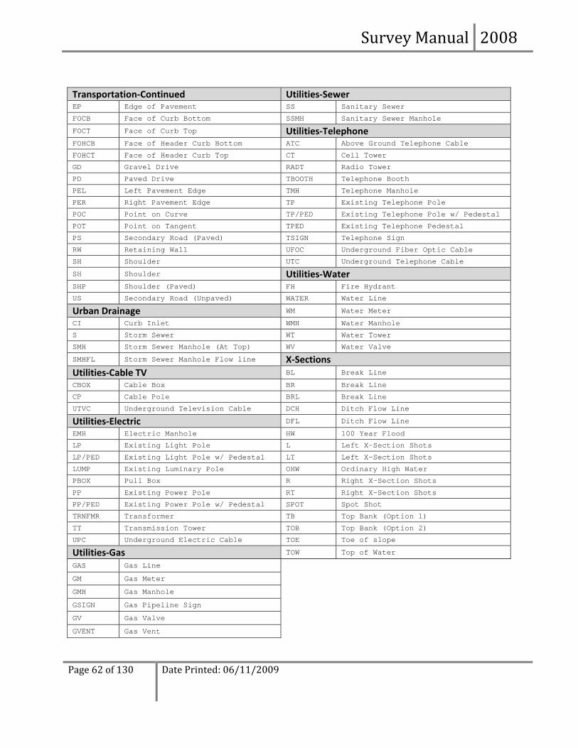
Survey Manual 2008
Page 62 of 130
Date Printed: 06/11/2009
Transportation‐Continued Utilities‐Sewer EP Edge of Pavement SS Sanitary Sewer
FOCB Face of Curb Bottom SSMH Sanitary Sewer Manhole
FOCT Face of Curb Top Utilities‐Telephone FOHCB Face of Header Curb Bottom ATC Above Ground Telephone Cable
FOHCT Face of Header Curb Top CT Cell Tower
GD Gravel Drive RADT Radio Tower
PD Paved Drive TBOOTH Telephone Booth
PEL Left Pavement Edge TMH Telephone Manhole
PER Right Pavement Edge TP Existing Telephone Pole
POC Point on Curve TP/PED Existing Telephone Pole w/ Pedestal
POT Point on Tangent TPED Existing Telephone Pedestal
PS Secondary Road (Paved) TSIGN Telephone Sign
RW Retaining Wall UFOC Underground Fiber Optic Cable
SH Shoulder UTC Underground Telephone Cable
SH Shoulder Utilities‐Water SHP Shoulder (Paved) FH Fire Hydrant
US Secondary Road (Unpaved) WATER Water Line
Urban Drainage WM Water Meter
CI Curb Inlet WMH Water Manhole
S Storm Sewer WT Water Tower
SMH Storm Sewer Manhole (At Top) WV Water Valve
SMHFL Storm Sewer Manhole Flow line X‐Sections Utilities‐Cable TV BL Break Line
CBOX Cable Box BR Break Line
CP Cable Pole BRL Break Line
UTVC Underground Television Cable DCH Ditch Flow Line
Utilities‐Electric DFL Ditch Flow Line
EMH Electric Manhole HW 100 Year Flood
LP Existing Light Pole L Left X-Section Shots
LP/PED Existing Light Pole w/ Pedestal LT Left X-Section Shots
LUMP Existing Luminary Pole OHW Ordinary High Water
PBOX Pull Box R Right X-Section Shots
PP Existing Power Pole RT Right X-Section Shots
PP/PED Existing Power Pole w/ Pedestal SPOT Spot Shot
TRNFMR Transformer TB Top Bank (Option 1)
TT Transmission Tower TOB Top Bank (Option 2)
UPC Underground Electric Cable TOE Toe of slope
Utilities‐Gas TOW Top of Water
GAS Gas Line GM Gas Meter GMH Gas Manhole GSIGN Gas Pipeline Sign GV Gas Valve GVENT Gas Vent

Survey Manual 2008
Page 63 of 130
Date Printed: 06/11/2009
The following is an example of how the points were processed with GeoPak based on alphabetic descriptions used in the field.
TOPO11.COR 1, 10000.00, 10000.00, 201.00, HVCM 2, 11717.89, 9333.30, 203.21, GD, L; ASPHALT 3, 11707.85, 9351.25, 203.35, GD 4, 11716.10, 9386.77, 202.92, GD, EL 5, 11725.15, 9372.63, 204.35, GAS, L 6, 11718.89, 9361.48, 204.56, XROW, L 7, 11718.90, 9361.75, 204.91, PP, L 8, 11702.91, 9387.80, 203.27, GD, L 9, 11689.87, 9358.36, 202.04, GD 10, 11667.83, 9349.93, 205.02, GD, EL 11, 11712.13, 9356.29, 203.24, RCP18, L 12, 11688.69, 9363.81, 203.00, RCP18, EL 13, 11706.99, 9325.35, 204.20, PEL, L 14, 11699.45, 9302.57, 204.51, PER, L 15, 11688.11, 9265.71, 203.13, XROW1, L 16, 11686.64, 9261.01, 202.32, WATER, L 17, 11566.30, 9410.56, 205.46, PP, L 18, 11402.72, 9360.82, 205.70, XROW1, EL 19, 11400.39, 9356.91, 205.48, WATER, EL 20, 11370.10, 9411.51, 204.10, PER, EL 21, 11376.63, 9434.96, 204.30, PEL, EL 22, 11434.13, 9455.70, 204.10, XROW, EL 23, 11417.97, 9431.58, 204.03, GD, L; GRAVEL 24, 11386.86, 9442.45, 204.36, GD1, L 25, 11417.18, 9447.19, 204.70, GD 26, 11402.76, 9459.58, 204.56, GD1 27, 11434.48, 9494.19, 205.34, GD, EL 28, 11419.36, 9499.66, 203.45, GD1, EL 29, 11401.10, 9465.65, 204.67, PP, EL 30, 11398.48, 9478.71, 203.30, GAS, EL 31, 11421.24, 9450.68, 202.20, RCP24, L 32, 11397.94, 9458.15, 202.45, RCP24, EL

Survey Manual 2008
Page 64 of 130
Date Printed: 06/11/2009
4.2.4 Vertical Separate (Cross-sections) With this method, the horizontal data could be collected as stated above except you could leave off the elevation and gather the vertical ground information as cross‐sections and profiles about staked baselines. Cross‐sections shall be collected along all proposed roadway alignments, alignments established for existing roadways. Cross‐sections for waterways, as described in the DRAINAGE section, and for Railroads crossing the proposed alignment, as described in the TOPOGRAPHY section, is also required.
Cross‐sections shall be taken at 100 feet intervals for rural projects and 50 feet intervals for urban projects. These intervals may also be appropriate on 3R projects, depending on the variability of earthwork along the project. Other factors that may influence the frequency of cross‐sections include the presence of intersections, extent of driveway and turnout construction or reconstruction, ADA related work, drainage improvements, etc. Where a cross‐section is not required at property ramps or driveways, a perpendicular profile is required at the centerline of the ramp/driveway in order to design the new property ramp or driveway. Enough coverage shall be taken so as to ensure that the proposed embankment will fit on the cross‐sections. It is the responsibility of the Project Engineer to determine the limits needed but the following table provides normal coverage values.
C.L. to C.L. Spacing of Lines Location of C.L. Survey Distance Left Distance Right
60‐125 feet C.L. of Median 150 feet Outside C.L. of Left Lane (Min.)
150 feet Outside C.L. of Right Lane (Min.)
Please Note: For undivided sections (five lane and transitional areas), the sections shall extend 150 feet left and right of the centerline.
Cross‐sections can be submitted as an ASCII text file in the format as described below or processed with GeoPak and submitted in working x‐section design files. The ASCII text file(s) submitted should be named XS*.COR where * is the name of the baseline the cross‐sections were taken about. (i.e. XS49.COR, XSLRWEST.COR, etc.)
An example of the format is shown below.
Please Note: It is critical that the survey baseline the cross‐sections were taken about is identified at the top of this ASCII text file, and that the columns of data are identified as to what each represents (i.e. PNUM, N, E, ELEV, etc.), as shown below.
X‐Sections for Hwy 49 are as follows:
Point Number
Northing Coord Easting Coord Elevation Description
500 570155.69982000 733291.65462000 173.929 tp 501 569793.03090000 733361.02800000 176.773 CL82+75.000 502 569790.51288000 733353.01379000 176.550 LT82+75.000 503 569788.90288000 733346.96199000 176.476 LT82+75.000 504 569786.78962000 733340.03627000 176.384 LT82+75.000 505 569785.14653000 733333.68831000 176.309 LT82+75.000 506 569784.59460000 733332.47066000 176.440 LT82+75.000 507 569782.43075000 733325.77248000 176.531 LT82+75.000 508 569794.15875000 733364.36214000 176.741 RT82+75.000

Survey Manual 2008
Page 65 of 130
Date Printed: 06/11/2009
509 569794.42502000 733365.52070000 176.460 RT82+75.000 510 569795.00734000 733367.43856000 175.660 RT82+75.000 511 569796.02438000 733369.87337000 175.622 RT82+75.000
4.3 Highway Surveys (Deliverables) This section describes what shall be submitted to the Roadway Design Division in regards to Preliminary Surveys. All survey data shall be submitted with form RWD‐200. Data shall be submitted electronically unless specified otherwise in this manual. Microstation is the electronic drafting package the data shall be submitted in and Roadway Design’s CADD standards, as stated by the CADD Manual, shall be followed. GeoPak is the civil software which shall be used to load points into Microstation, create alignments, create DTM’s, cut cross‐sections/profiles, etc. Specific steps for using GeoPak to perform these tasks are available in Roadway Design’s GeoPak User’s Guide.
The electronic data should be submitted through email, over the network or on CD/DVD to the Assistant Roadway Design Engineer or his/her designee. Any plotted data and/or notes shall be bound together and also submitted with the following label.
TO: ROADWAY DESIGN DIVISION (83‐01) INITIAL PRELIMINARY SURVEY or ADDITIONAL SURVEY DISTRICT: PROJECT NUMBER:
At a minimum, the completed survey shall consist of the items listed and summarized below. Each is described in detail on the following pages.
1. VERTICAL DATA (EXISTING GROUND) ‐ ELECTRONIC or NOTES (As described in detail in the VERTICAL (EXISTING GROUND) section below.)
a. DTM ‐ Digital Terrain Model (Preferred)
Existing ground data collected with XYZ spot shots and break lines shall be processed with GeoPak. A GeoPak TIN shall be created and cross‐sections shall be extracted about all proposed and/or existing alignments. All cross‐section design files shall be submitted with the TIN file, 3‐D design file showing spot shots and break lines, and the GPK file.
b. Baseline tied data (Optional)
Existing ground cross‐sections taken 90 degrees from staked baseline stations shall be submitted as an XYZ ASCII text file, or in a Microstation design file after being processed with GeoPak.
Existing ground profiles taken about a staked baseline, shall be submitted in the GPK and plotted on the profile part of a plan/profile sheet with the corresponding baseline shown in the plan part of this sheet.
2. HORIZONTAL DATA ‐ ELECTRONIC – All topography must be submitted electronically in a 2‐D Microstation design file called TOPO.DGN. Additional topographic survey data should be submitted in a design file called Tdate.DGN where date is the date of submittal.

Survey Manual 2008
Page 66 of 130
Date Printed: 06/11/2009
3. DRAINAGE DATA ‐ PLOTTED (For Drainage Areas 1,000 acres or greater) – Drainage data for drainage areas 1,000 acres or greater, or for smaller areas involving a bridge, shall be placed on plan/profile sheets and submitted as paper plots. Associated Microstation files shall also be submitted.
4.3.1 Vertical Data (Existing Ground) Vertical data (existing ground) can be submitted by one of the following methods depending on how the data was collected.
Control Method Submittal Type I) Spot Shot / Break line Survey (DTM) GeoPak Working X‐Section design file, *.DAT, *.TIN II) 90^ to baseline (Cross‐section) XYZ ASCII text file or GeoPak Working Cross‐section
design file. Please Note:
1. If a GeoPak Working X‐Section file is submitted, GeoPak’s Coordinate Geometry database file (JOB*.GPK) shall also be submitted.
2. Existing ground elevations will be tied to the project’s established vertical datum.
4.3.2 Horizontal (TOPO) All topography data, regardless of the collection method, should be submitted in a 2‐D Microstation design file called TOPO.DGN. TOPO.DGN shall consist of a single long map with State Plane coordinate integrity maintained. Additional surveys (Surveys submitted after the initial survey submittal) submitted in Tdate.DGN should also be on the same coordinate system. All aspects of this design file should adhere to the Roadway Design CADD Manual including Microstation Design file working units, level symbology, line styles, cell libraries, text styles, etc.
Roadway Design provides the following directories to aid you in meeting the CADD standards mentioned above.
RWD\ GROUP\ < English Microstation seed design files, cell libraries, custom menus, etc. INPUT\ < English MDOT GeoPak files
These files are downloadable from Roadway Design’s FTP Site located at http://ftp.mdot.state.ms.us/.
Two items which should help specifically when loading or working with topography in a design file include:
RWD‐SVY.SMD – This is MDOT’s GeoPak Survey Database containing PCODES which should be used in the field to describe the type of data a shot represents. These PCODES are tied with Microstation cell libraries and custom line styles and topography is automatically drawn.
DZINE Bar Menu – Microstation menu which provides an easy way to set proper existing symbology.
It is important that all topography likely to be affected by, or that will affect, the proposed road be accurately located.
4.3.3 Elements of the TOPO.DGN The following section describes in detail what should be submitted to the Roadway Design Division. The TOPO.DGN should include:
1. Horizontal and Vertical Control with appropriate labels. Cells have been created in RWD.CEL and are listed below. Mathematical and Descriptive location shall be provided on these labels.

Survey Manual 2008
Page 67 of 130
Date Printed: 06/11/2009
PCM – Primary Control Marker which contains Northing & Easting coordinates & Elevation.
HVC – Secondary Control Marker which contains Northing & Easting coordinates & Elevation.
HC – Secondary Control Marker which contains Northing & Easting coordinates with no Elevation.
BM – Vertical Control Point which contains Elevation only.
2. Alignment information of the centerline construction of all proposed alignments. This includes tangent bearings, curve and spiral data, and stationing. Alignments should also be stored and submitted in GeoPak’s Coordinate Geometry database file (JOB*.GPK).
a. The arc definition for horizontal curves will be used entirely in highway location.
b. All survey stationing will be done from south to north and west to east.
c. Stationing should always begin with a station large enough to avoid any minus stations if the survey is extended for additional information. When tying to an existing road, the survey should extend far enough past the proposed beginning of the project to provide information necessary for the designer to make a good vertical and horizontal tie.
d. Check tangent bearings against curve tangent bearings to assure there are no kinks at the PC & PT of curves.
3. Location of existing roads. This includes edge of pavement and existing centerline information including tangent bearings, curve and spiral data, stationing, and ties to the centerline construction of the primary route. Topography should be collected a minimum of 650 feet in each direction from the Existing Road – Mainline Construction intersection.
a. Do not send in numerous connected shots (PI’s) on the existing centerlines. For example: If an existing alignment has one curve and two tangents on each side of the curve, three elements should be used in Microstation to show this alignment; one line representing the back tangent, one arc representing the curve, and one line representing the forward tangent.
b. Alignments should be created from field collected existing centerline shots, existing Right‐of‐Way markers, bridge ends, major drainage structures and any other readily identifiable feature shown on the as‐built plans. The “Best Fit” alignment should fit as close to these individual points as possible. Although it is probably impossible to recreate the alignment to match the As‐Built alignment, the As‐Built alignment should be studied and matched as closely as possible when creating the “Best Fit” alignment.
4. Alignment information of survey baseline if cross‐sections taken about a baseline other than the CL construction or existing alignments, except for drainage alignments (See Drainage section below.)
5. Railroad Crossings (At Grade) (See Bridge Section for Grade Separation requirements or if type intersection is unknown.)
a. Profile of the top of both rails 650 feet each direction.
b. Vertical Ground Data should be collected 250 feet in each direction along the tracks within the railroad Right‐of‐Way. If the road coverage extends beyond 250 feet, the limits of the vertical data along the railroad should extend to it.
c. Station and bearing of each set of rails.
d. Alignment of all tracks, 650 feet each direction with curve information (if any) computed.

Survey Manual 2008
Page 68 of 130
Date Printed: 06/11/2009
e. Topography within the railroad Right‐of‐Way, 650 feet each direction, including switching devices, signal devices, control boxes, and utilities (especially fiber optic cables).
f. Name of the railroad.
g. Present railroad Right‐of‐Way.
h. Distance and direction to the nearest mile post in each direction and description of same.
i. Size, type, invert elevation and condition (if required) of existing drainage structures with the direction of flow in field drains and channels indicated by arrows.
6. Existing driveways horizontal location & type.
7. Existing Property data as stated in the property data & existing Right‐of‐Way chapter.
8. Existing buildings with description, e.g.: 1SF – Residence (One Story Frame), names and types of businesses.
9. Existing Storm Drains
a. Inside diameter of pipe
b. Type of pipe
c. Length
d. Direction of flow
e. Upstream & downstream flow line elevation
10. Land Character – The land character of rural areas such as pasture, second growth, cultivated, swampy, etc., should be noted.
a. Stock and Equipment Passes – It is the responsibility of survey parties to recommend locations where stock and/or equipment passes should be placed for proposed highways. The primary indicator for a stock pass is the dividing of a large area specifically used for pasture. Therefore, all pasture lands should be carefully noted. Also, field personnel should be cautioned against discussing possible locations with property owners. The assurance that a stock and/or equipment pass will be considered during the design process is usually the best response.
b. Trees – Trees showing significant age or historical value which may be affected by construction should be shown with the size and type. The edges of wooded areas should also be identified.
11. Waters/Wetlands
a. Wetland areas should be outlined and identified with the classification of “WETLAND”. The Routine Wetland Determination Data form from the Corps of Engineers Wetlands Delineation Manual should be completed for each wetland site. This form is also available through Roadway Design’s Intranet Site Error! Hyperlink reference not valid. ‐> Resources ‐> Forms.
b. All ponds, streams, rivers, etc. should be identified horizontally by the top banks, as waters of the US.
12. Utilities
a. All existing utilities within the project area should be shown.

Survey Manual 2008
Page 69 of 130
Date Printed: 06/11/2009
b. Owners – The owner of each utility should be shown. Include name, address, contact person, and phone number.
c. Limits – When more than one utility company supplies the same service, the limits of each owner’s service area should be indicated.
d. Location and Profile – The location and depth of underground utilities should be determined as best possible. Profiles on gas lines and gravity‐flow sewer lines are especially critical. However, gas lines should never be sounded with a steel rod.
e. All underground utilities which may be affected by roadway or structure construction will be shown in the topography design file. Location should be coordinated through MS ONE CALL (1‐800‐227‐6477).
f. Overhead – Overhead utility lines between poles will not be shown on present layout plots. The direction of the lines will be indicated by a short line through the cell representing the pole.
g. Signals – At signalized intersections, the signal heads, span wires, poles and controller should be recorded and shown.
h. The pole or tower number should be recorded, if available, for major transmission lines.
i. Type of Utility – The type of service for each underground line and for each utility pole should be noted using Roadway Design’s symbology.
j. Storm Sewers and Sanitary Sewers – Elevations should be taken on the top and bottom of each manhole or catch basin and on the invert at each end of every pipe, including pipes that terminate in manholes. It is advisable to develop a table of elevations and a numbering system for the pipes of a sewer system.
k. Septic Tanks and Drain Fields – In areas where there are no municipally owned sewer and water systems, information shall be shown on all developed property regarding sewage disposal and water supply. All septic tanks and field lines near the proposed roadway should also be located. However, a note indicating the location of facilities a considerable distance from the proposed roadway (or behind a building) will suffice.
l. Wells – Any drilled wells (gas, oil, or water). The name and address of the driller and name of the property owner at the time the well was drilled should also be noted. If this information is available, it should be listed in the topography design file adjacent to the well site.
m. Location for Pay Item Purpose – Responsibility for payment (Utility Co. or State) to relocate a utility is determined by its location in or out of present Right‐of‐Way. When utilities are close to the present Right‐of‐Way or user’s line, care should be taken to accurately locate the utility.
n. Occasionally problems are encountered in the coordinating of the location of underground utilities. Any such problems should be recorded in the project field notes.
13. Underground Petroleum Storage Tanks – The disposition of property containing underground petroleum storage tanks is of utmost importance. Environmental requirements call for expensive procedures to ensure that leakage does not occur during any activity affecting the property. Because of the expense involved, the MDOT must carefully consider such property when planning or constructing a roadway project. The ideal solution would be to avoid such property. This, however, is not always possible.

Survey Manual 2008
Page 70 of 130
Date Printed: 06/11/2009
a. An attempt will be made to locate and identify all such property during the location review. Proposed alignments will then be located so that the property can be avoided if possible.
b. In the event that such property is unavoidable, all tanks should be located as accurately as possible and recorded in the topographic design file. Accurate location of the underground tanks is often difficult. However, all possible sources of information should be investigated (conversation with tenants, request for plans from owners, etc.).
c. Occasionally property with tanks not identified in the location committee report will be encountered. This is more likely when the tanks are not in use. The property and existing tanks should be brought to the attention of the District Engineer for consideration of moving the survey line to avoid the property. If this is not possible, the property and tanks should be located as discussed above.
d. Approximate size of tank in gallons.
4.3.4 Bridge Specific
Submittal Format
All data must be submitted in plotted and electronic (.dgn) format Electronic files shall be submitted with the survey. Electronic survey files (point‐shots, cross‐sections, etc.) shall be submitted in Microstation (.dgn) format under the filename BRIDGEDATA[1,2,3…].dgn
Roadway and Highway Crossings (Grade Separation) 1. Obtain the skew angle, bearing of the roadway, and intersection stations at the intersection of
mainline centerline roadway and underlying roadway(s).
2. Obtain cross‐sections at 25 foot intervals along and out to at least 100 feet both sides of the underlying roadway(s) to the limits of the MDOT right‐of‐way. Locate all break lines along each cross‐section including but not limited to:
a. Edge of travel lane
b. Edge of shoulder
c. Top and bottom of ditches
d. All slope breaks
e. Roadway crown and lane breaks

Survey Manual 2008
Page 71 of 130
Date Printed: 06/11/2009
Example:
3. Locate all existing topographical points of interest including but not limited to:
a. Existing structures
b. Drainage structures
c. All visible substructure (e.g. centerline bents, piles, columns)
d. All utilities and utility markers
e. Provide cross‐sections along the mainline as submitted to Roadway Design Division. (Electronic Files only)
4. Obtain elevation(s) on existing bridge structures at points of known plan elevation(s) using the datum of the new survey (0.02’ accuracy relative to project control).
5. Locate the minimum vertical clearances to any existing structure, from the high point of the roadway to bottom of all exterior girders.
Railroad Crossings (Grade Separation) 1. Obtain the skew angle at the intersection of centerline railroad with mainline centerline survey and
centerline approach roadway(s).
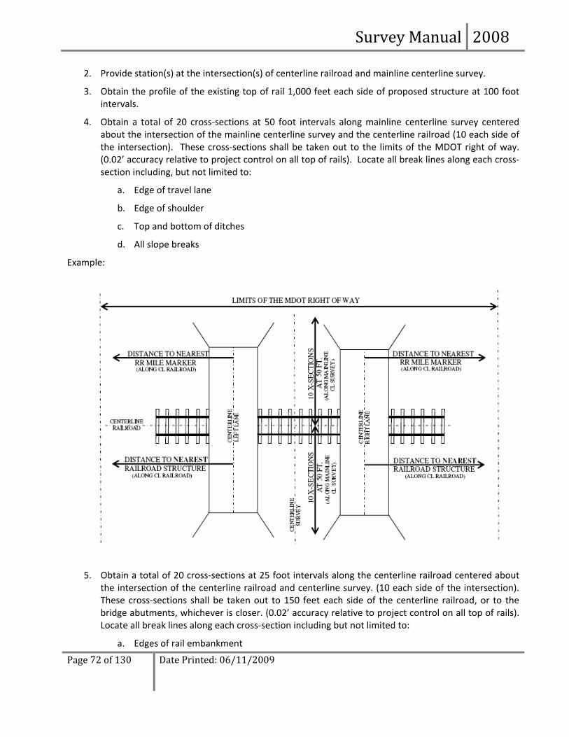
Survey Manual 2008
Page 72 of 130
Date Printed: 06/11/2009
2. Provide station(s) at the intersection(s) of centerline railroad and mainline centerline survey.
3. Obtain the profile of the existing top of rail 1,000 feet each side of proposed structure at 100 foot intervals.
4. Obtain a total of 20 cross‐sections at 50 foot intervals along mainline centerline survey centered about the intersection of the mainline centerline survey and the centerline railroad (10 each side of the intersection). These cross‐sections shall be taken out to the limits of the MDOT right of way. (0.02’ accuracy relative to project control on all top of rails). Locate all break lines along each cross‐section including, but not limited to:
a. Edge of travel lane
b. Edge of shoulder
c. Top and bottom of ditches
d. All slope breaks
Example:
5. Obtain a total of 20 cross‐sections at 25 foot intervals along the centerline railroad centered about the intersection of the centerline railroad and centerline survey. (10 each side of the intersection). These cross‐sections shall be taken out to 150 feet each side of the centerline railroad, or to the bridge abutments, whichever is closer. (0.02’ accuracy relative to project control on all top of rails). Locate all break lines along each cross‐section including but not limited to:
a. Edges of rail embankment
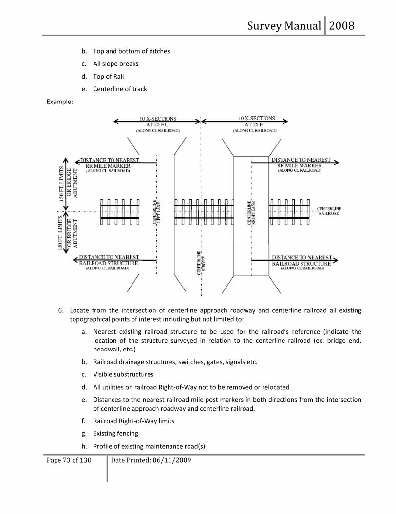
Survey Manual 2008
Page 73 of 130
Date Printed: 06/11/2009
b. Top and bottom of ditches
c. All slope breaks
d. Top of Rail
e. Centerline of track
Example:
6. Locate from the intersection of centerline approach roadway and centerline railroad all existing topographical points of interest including but not limited to:
a. Nearest existing railroad structure to be used for the railroad’s reference (indicate the location of the structure surveyed in relation to the centerline railroad (ex. bridge end, headwall, etc.)
b. Railroad drainage structures, switches, gates, signals etc.
c. Visible substructures
d. All utilities on railroad Right‐of‐Way not to be removed or relocated
e. Distances to the nearest railroad mile post markers in both directions from the intersection of centerline approach roadway and centerline railroad.
f. Railroad Right‐of‐Way limits
g. Existing fencing
h. Profile of existing maintenance road(s)

Survey Manual 2008
Page 74 of 130
Date Printed: 06/11/2009
7. Provide alignment of railroad and mainline as submitted to Roadway Design Division.
8. Obtain elevation(s) on existing bridge structures at points of known plan elevation(s) using the datum of the new survey (0.02’ accuracy relative to project control).
Bridge Widening
1. Obtain bridge deck elevations along the crown line and gutter line at the abutments, mid‐spans, joints and bents (0.02’ accuracy relative to project control)
2. Locate bents limits of visible substructure nearest the portion of structure to be widened along the alignment.
a. Footings (corners)
b. Round Columns (3 points)
c. Diamond Shaped Columns (6 points)
3. Complete survey required for hydraulic, road and highway crossing, or railroads as described in this survey manual.
4. Obtain elevations on the top of bent caps at each end of the cap using the datum of the new survey (0.02’ accuracy relative to project control).
4.3.5 Drainage Drainage data will be submitted in different ways depending on the size of the drainage areas. The information below describes what should be collected and how it should be submitted.
Drainage Map A drainage map will be prepared for every project that has drainage crossing the survey centerline, unless instructed otherwise. Large areas may be delineated on quad sheets or aerial maps. Smaller areas should be surveyed in the field and shown in TOPO.DGN. Any drainage structures which control flow into or away from the immediate project area (where flow crosses the centerline) should be located and their size noted.
The following information should be provided: • An outline of the drainage area with numerical area provided. • The location where the drainage crosses the mainline centerline survey (provide station).
4.3.5.1 Hydraulic Information for the Bridge Division – Drainage Areas 1,000 Acres or Greater
ALL DATA MUST BE IN PLOTTED FORM ON PLAN/PROFILE SHEETS Electronic files shall be submitted with the survey. As stated in Roadway Design’s CADD Manual, “All Drainage Alignments shall be placed in a file called ALIDRN.DGN, all drainage Plan/Profile sheets shall be named and submitted as discussed under the filename WK***[a, b, c].dgn”.
For Structure Replacement on the Existing Alignment, obtain the following: 1. A typical (representative) flood‐plain profile including the channel section. Show the location of the
floodplain profile with references to the mainline centerline survey.

Survey Manual 2008
Page 75 of 130
Date Printed: 06/11/2009
2. A profile along the existing roadway showing the finished grade.
3. A ground‐line profile along any proposed detour.
4. A stream‐traverse 500 feet upstream and 500 feet downstream for typical crossings.
5. Typical channel sections normal to the channel (at least one upstream and one downstream), showing elevations and corresponding horizontal dimensions from the traverse baseline.
6. A stream profile (taken at the deepest part of the stream) extending 500 feet upstream and 500 feet downstream, referencing it to the traverse baseline.
7. The water‐surface elevation at both ends of the stream profile and at the bridge with a date included.
8. Drainage data as follows:
a. High‐Water: Provide elevations, approximate dates, and sources of information for floods of significance. The location of the high‐water marks should be clearly designated relative to the centerline of the proposed route. Provide high‐water marks both upstream and downstream of the mainline centerline survey.
b. Drainage area at the site.
c. Comment on drift and bank stability.
9. Obtain data on the existing bridge(s) as follows:
a. Profile along centerline beneath the bridge with additional detail of any scour holes.
b. Details shall be provided in separate plan and profile views to show the size, location, and extent of any scour holes.
c. Bottom elevation of the low stringers.
d. Type of bridge, span lengths, and skew if applicable.
e. Finished Grade Profile along the bridge and the approach roadway to the edge of the floodplain, or as directed by the Bridge Engineer.
Note: The information in item 9 above, with the exception of 9b,is also needed for existing structures on other highways, county roads and railroads within 1000 feet of the mainline centerline survey.
10. Provide description and elevation of benchmarks nearest the existing bridge or proposed channel crossing including the origin of datum.
For The Hydraulic Design of Structures on a Relocated Alignment: The items listed above will be required except item number 2 may be omitted in a situation where the new alignment is not in the vicinity of the existing alignment.
In most situations, the centerline profile will suffice for item number 1. Contact Bridge Division Hydraulics if there is a question about whether the centerline profile can serve as a floodplain profile.
Where twin bridges are proposed, a ground line profile shall be obtained along the centerline of both lanes.

Survey Manual 2008
Page 76 of 130
Date Printed: 06/11/2009
For Widening On The Existing Alignment : 1. When existing bridges are to be widened, obtain a complete hydraulic survey (as described under
“For Structure Replacement on the Existing Alignment . . .”).
2. When existing box bridges or culverts are to be lengthened, obtain a complete hydraulic survey if either one or both of the following conditions applies:
a. The National Flood Insurance Program Maps show a Regulatory Floodway to be in effect. These maps are available at www.fema.gov or contact the Bridge Division Hydraulics Section for assistance.
b. The site shows signs of channel degradation, scour, and/or bank instability.
4.3.7 Hydraulic Information for the Roadway Design Division – Drainage Areas from 200-1,000 Acres
1. Profile of present highway presenting the finish grade (include stream channel).
2. Ground line profile along proposed detour.
3. A stream‐traverse 500 feet upstream and downstream.
4. A stream profile (taken at the deepest part of the stream, 200‐300 feet upstream and downstream) related to the traverse.
5. Typical channel sections normal to the channel (at least one upstream and one downstream) related to the traverse.
6. Water‐Surface elevation at both ends of the stream profile.
7. High‐water marks upstream and downstream.
8. Drainage area.
9. Comment on drift and bank stability.
10. Size, length, skew, material type, and upstream and downstream flow lines, of existing drainage structures. Cross‐sections are also required at each existing drainage structure location. If structure is skewed, a cross‐section is required for the upstream and downstream end.
11. Descriptive information of existing culverts serving the same drainage area under nearby highways and railroads that will possibly affect MDOT structures.
If a DTM is created, items 1, 2, 3, 4, 5 of the information shall be extracted from the DTM by the Project Office. The remainder of the data should be submitted as notes or in TOPO.DGN except for Item 10 which shall be submitted in TOPO.DGN. See DTM section for submittal type if XYZ Spot Shot/Break line survey collected.
If the vertical ground data is collected as cross‐sections, items 1 and 2 can be extracted by Roadway Design, item’s 3, 8, and 10 should be submitted in TOPO.DGN. Item 5 can be submitted as described in the Vertical Ground section of this chapter. Item 10 shall be submitted in TOPO.DGN. The rest can be submitted as notes or in TOPO.DGN

Survey Manual 2008
Page 77 of 130
Date Printed: 06/11/2009
4.3.8 Hydraulic Information for the Roadway Design Division – Drainage areas less than 200 acres
1. High‐water marks upstream and downstream (TOPO.DGN or Notes).
2. Drainage area (TOPO.DGN).
3. Descriptive information of existing culverts serving the same drainage area under nearby highways and railroads (TOPO.DGN).
4. Sufficient channel flow line profile to establish the natural channel slope, 200‐300 feet upstream and downstream with a stationed traverse line.
5. Typical channel sections upstream and downstream normal to the channel with location identified on traverse line mentioned in previous item.
6. Size, length, skew, material type, and upstream and downstream flow lines, of existing drainage structures (TOPO.DGN). Cross‐sections are also required at each existing drainage structure location. If structure is skewed, a cross‐section is required for the upstream and downstream end.
4.3.9 Property Data and Existing Right-of-Way Property data should be submitted in a Microstation DGN file called PROPERTY.DGN with elements drawn on Roadway Design’s symbology. See the Right‐of‐Way and Property Surveys section of this manual for more detail.
4.4 Site Surveys (Deliverables) for ASU All Topography is to be provided in a Microstation 2‐D Design File along with contours and spot elevations. A Microstation 3‐D Design File can also be included. Furnish electronic data on CD or send by e‐mail and also send one print of each drawing. Architectural Services does not have Geopak. Furnish Microstation DGN files with all pertinent referenced drawing files to the same scale and orientation.
1. A minimum of one permanent benchmark on site for each four acres and a description and elevation to nearest .01 foot.
2. Show contours at 1 foot intervals; error shall not exceed one‐half contour interval.
3. Spot elevations at street intersections and at 50 feet on center of curb, sidewalk and edge of paving, including far side of paving. If elevations vary from established grades, state both grades.
4. Plotted location of structures, paving and improvements above and below ground. This includes wiring above ground and water, gas, sewer, phone, fiber optic, and power lines below ground.
5. Provide finish floor elevations at each entrance of existing buildings on the property.
6. If there is a possibility of the site flooding, show approximate 50 and 100 year flood elevations.
7. Utility information. The following information is to be shown based on recorded information and on surface evidence.
a. Show locations, sizes, depths and pressures of water and gas mains, central steam and other utilities including, but not limited to, buried tanks and septic field servicing, or on, the property.

Survey Manual 2008
Page 78 of 130
Date Printed: 06/11/2009
b. Show location of fire hydrants available to the property and the size of the water main serving each.
c. Show locations, elevations and characteristics of existing power, cable television, street lighting, traffic control facilities and communications systems above and below ground. Above ground utilities shall show wires between poles.
d. Show locations, sizes, depths and directions of flow of sanitary sewers, combination sewers, storm drains and culverts servicing, or on, the property. Also show locations of catch basins and manholes, and inverts of pipe at each.
e. Show closest existing connection of each utility, even if it is not on site.
f. Give name of the operating authority, including contact person and phone number, for each utility indicated above.
8. Spot elevations on paving or other hard surfaces, including existing finish floor elevations at all entry doors, shall be to the nearest .01 foot; on other surfaces, to the nearest .10 foot.
9. When it is the responsibility of the District to prepare the building pad prior to construction, the survey will be revised by the District to show improvements and changes done.
4.5 Preliminary Plans This section describes survey related requirements of Design Plans and Property Maps.
Cover sheets for all plans showing grid distance shall have a note similar to the one below. This note should be submitted in TOPO.DGN along with the survey at which point it will be moved to the Cover Sheet:

Survey Manual 2008
Page 79 of 130
Date Printed: 06/11/2009
Coordinate integrity must be maintained for the project in all applicable design files.
Alignments stored in GeoPak’s Coordinate database file(s) should be used as is and passed from division to division.
4.6 Example Survey The examples on the following pages represent a sample survey.

Survey Manual 2008
Page 80 of 130
Date Printed: 06/11/2009

Survey Manual 2008
Page 81 of 130
Date Printed: 06/11/2009

Survey Manual 2008
Page 82 of 130
Date Printed: 06/11/2009

Survey Manual 2008
Page 83 of 130
Date Printed: 06/11/2009
4.7 References – Preliminary Surveys • Wyoming Department of Transportation Survey Manual; Wyoming DOT; 2001 • Tennessee Department of Transportation Survey Manual; Tennessee DOT; March 13, 2001

Survey Manual 2008
Page 84 of 130
Date Printed: 06/11/2009
5.0 Photogrammetric Surveys
5.1 Introduction “Photogrammetry is the art, science, and technology of obtaining reliable information about physical objects and the environment through processes of recording, measuring, and interpreting photographic images and patterns of electromagnetic radiant energy and other phenomena.”1 “In mapping, measurements on photographs replace field surveys, in whole or in part; consequently, the use of photographs and photogrammetry in mapping is often referred to by such terms as ‘aerial survey’ or ‘photogrammetric survey’.”2 Aerial surveys produce maps and map products using photogrammetric means from vertical aerial imagery. The imagery can be in either hard copy or digital form, but it is essential that the imagery collection is precisely accomplished and the imagery itself is strictly metrically controlled (e.g., having very tight tolerances on factors such as film dimensional stability, image space parameters, platen flatness, lens distortion, etc.) to ensure that precise measurements can be made from it. The map data is compiled in a visual three dimensional (3‐D) environment and is used to produce spatially accurate planimetric maps, digital terrain models (DTM), and products derived from them, e.g., contours and cross‐sections. Photogrammetric maps and map products may be in hard copy or digital form as specified for each project by the MDOT State Surveyor.
As used in this document, “imagery” refers to any product generated through a photographic process derived from capturing reflected sunlight. Most commonly, this would be photography using visible light wavelengths. It could also encompass imagery created from capturing reflected radiation in the infrared (IR) or ultraviolet (UV) portions of the spectrum. Broadly speaking, “remote sensing” includes traditional aerial photography. In the context of this document, however, the term “remote sensing” refers to all airborne data that falls outside of the range between IR and UV, or that has been collected using artificially radiated energy to illuminate the ground surface. LiDAR is an example of a product that falls within this latter category for our purposes. It is beyond the scope of this chapter to address the use of products collected from extra‐atmospheric platforms.
“Versatile as the applications of photogrammetry are, however, field surveys are still required to supply the basic control (both horizontal and vertical) needed to determine the scale, azimuth, and attachment to datums of the photogrammetric”3 maps and map products. Thus, some type of ground control survey is required as part of any aerial survey, either to supply the connection between the photography and the terrestrial datum, or to verify the accuracy of that connection.
5.2 Flight Requirements MDOT has established specifications to define the collection imagery and production of photogrammetric mapping products to ensure uniform quality, and to ensure that all products meet the requirements of MDOT users.
1 Manual of Photogrammetry, pp 1 2 Ibid., pp 1-2 3 Ibid, pp 413

Survey Manual 2008
Page 85 of 130
Date Printed: 06/11/2009
5.2.1 Flight Lines The areas to be photographed will be outlined on the latest available highway county maps with a scale of 1 inch =1 mile (1:63,360). The photogrammetrist will design the flight lines for the photography and delineate such lines on a suitable map of a scale no smaller than that supplied by the Department. Generally, the flight lines will be parallel to each other and generally parallel to the longest boundary lines of the area to be photographed. The flight lines must be designed to obtain stereoscopic coverage of the entire area to be mapped, without gaps, but also without excessive extra coverage. Flight lines will be planned to ensure that the proper forward overlap and side overlap is obtained for all images.
“Forward overlap in the line of flight shall average not less than 57% or more than 62% at the mean elevation of the terrain, unless otherwise specified. Individual forward overlaps shall not be less than 55% or more than 68% excepting the situation where in a forward overlap in areas of low elevation must exceed 68% to attain the minimum 55% forward overlap in adjacent areas of higher elevation. Wherever there is a change in direction between two flight lines (other than between adjacent parallel flight lines) junction areas between the adjoining flight lines shall be covered stereoscopically by both lines.”4
Wherever there is a change in direction of the flight lines, vertical photographs at the beginning of a flight line shall give complete stereoscopic coverage (100%) of the area contiguous to the forward and back sections.
“Side overlap between adjacent parallel flight lines shall be 30% +/‐ 10% at the mean elevation of the terrain. In addition, any point on the flight line as flown shall not deviate from the flight plan location by a distance greater than 10% of the width of coverage of the photograph.”5 An exception to the foregoing requirement is where the strip area to be mapped is slightly wider than the area which can be covered in one flight strip of photographs, in which case side lap of up to 70% to take advantage of control is permissible.
5.2.2 Flying Height The nominal photo scale and required flight height above mean terrain will be noted on the flight maps. Mean terrain will generally be defined as the elevation of the primary transportation infrastructure or corridor to be imaged. Flying height will be derived from the required image collection scale based on the optical dimensions of the imagery collection system, i.e., focal length. Any departure from the specified flying height, required to achieve the required image scale, will not exceed ± 5%. 6 Image negatives having a departure from the specified scale of more than 5% for any reason, e.g., because of tilt or and changes in flight height, may be rejected.
The flying height above the average elevation of the ground shall be such that the collected imagery will yield photographic contact prints on paper or film, or contact and reduced‐size transparencies on optically flat glass, to the scale and size required by the photogrammetric mapping process used by, or on behalf of, MDOT to attain photogrammetric measurements and/or map scales, contour intervals, and accuracy required by MDOT for each specific project or purpose.
Planned flying height will be a function of the physical characteristics and dimensions of the optical system of the sensor to be employed, the scale of the imagery or other product to be collected, the scale of any
4 1995 Draft Standards for Aerial Photography, section 2.3.2 5 Ibid. section 2.3.3 6 Specifications for Vertical Aerial Photography, pp 6

Survey Manual 2008
Page 86 of 130
Date Printed: 06/11/2009
map products to be derived from collected imagery, and the scale and resolution of any imagery products to be created for MDOT.
5.2.3 Scale of Vertical Photography For planimetric mapping and DTMs to be compiled from aerial photography (whether hard copy or digital), the scale at which the images are collected, i.e., the original image scale, must be between 5 and 6 times smaller than scale at which the planimetric mapping is specified to be originally compiled. For example, if MDOT specifies that the plan maps will be originally compiled at a scale of 1 inch = 100 feet, then the imagery must be collected at a scale between 1 inch = 500 feet to 1 inch = 600 feet. Similarly, planimetric mapping to be compiled at an original scale of 1:1,000 would require imagery originally collected at a scale between 1:5,000 and 1:6,000. The exception to this rule is that planimetric mapping to be compiled at an original scale larger than 1:500, e.g., 1:250 “design scale” mapping, may be compiled from high quality aerial imagery, using top‐end stereo compilation equipment, collected at a scale of up to 1:2,500.7
5.2.4 Flight Conditions The illumination by sunlight falling on a unit of horizontal surface varies greatly with the sun’s altitude above the horizon. The amount of illumination from the sun at 30° is about two‐fifths of that at 60° altitude.8 Unless otherwise specified to meet unusual requirements, photogrammetric imagery should be obtained when the sun is at least 30° above the local horizon. A local solar position calculator, such as the one found at www.srrb.noaa.gov/highlights/sunrise/azel.html, can be useful in relating solar altitude to time of day.
Visible‐light imagery shall be collected only when clear, well defined images can be obtained. Images shall not be collected when the ground is obscured by haze, snow, smoke, dust, flood waters, or environmental factors that may obscure ground detail. Clouds and/or shadows of clouds must not appear in the aerial images. Neither should images contain shadows cast by topographic relief.
Flight conditions for collecting non‐image remotely sensed data should be appropriate and conducive to obtaining data of the highest possible quality with the minimum of missing or distorted data.
5.2.5 Equipment Images for photogrammetric mapping will be collected using aircraft and equipment produced, or modified (in the case of the aircraft), for the specific purpose of obtaining precise aerial imagery. MDOT prefers that no window at all is interposed between the camera / sensor lens and the ground to be imaged. “No window of glass or other material shall be interposed between the camera / sensor and the ground to be photographed unless said window is of optical quality (optically flat or neutral), free of scratches and blemishes, and will in no way degrade the resolution or accuracy of”9 the imagery or sensed data. It is important that the aircraft and imagining equipment must be operated by staff with meaningful experience in collecting aerial imagery and remotely sensed data. All cameras, imaging devices, and sensors used to collect images and data used for MDOT mapping projects will be of a type and configuration specialized for airborne applications. These devices must be calibrated and fully capable of capturing products with the geometric integrity and minimized distortion required for the high‐precision uses envisioned by MDOT.
7 Catalog of Photogrammetric Services, pp 11 8 Manual of Photogrammetry, pp 295 9 Specifications for Vertical Aerial Photography, pp 2

Survey Manual 2008
Page 87 of 130
Date Printed: 06/11/2009
5.2.6 Imagery The format and type of imagery to be produced and provided to MDOT as part of any photogrammetric mapping activity will be specified by the MDOT State Surveyor to meet the individual requirements of each project. Unless otherwise specified by the State Surveyor, all visible‐spectrum aerial imagery will be obtained as full natural color imagery.
5.3 Photogrammetric Control To make precise and meaningful measurements from aerial imagery or other electromagnetic data captured from an aircraft, it is essential to be able to accurately and precisely relate the images of objects and features to the actual objects or features on the ground surface. In other words, it is essential to be able to relate the image coordinate system to the ground (grid) coordinate system. This relationship is achieved, in part, by using field surveying methods to measure the positions and elevations of identifiable objects, “photo‐control points” in the classical usage, within the area covered by the imagery or data collection. “The accuracy required for the photo‐control points will depend upon the scale and accuracy requirements of the mapping, and upon the type of photogrammetric procedure to be used.”10
5.3.1 Photogrammetric Control Survey Many airborne mapping applications and practitioners rely solely on GPS in the aircraft to provide control for photogrammetric and remote sensing product creation. This approach is not accepted for MDOT projects at this time. For stereo‐compilation of mapping from imagery, MDOT requires that the process of photo measurement of ground control points and computation of an aerotriangulation solution be used to ensure that the mapping will meet MDOT requirements.
Photogrammetric control surveys should take advantage of the most productive and cost effective technology and methods available, while still ensuring that they meet the requirements of the project. GPS technology is the Department’s preferred method for photogrammetric control surveys, although more conventional methods are acceptable if conditions warrant their use. Given the advances in surveying technology, every photogrammetric control survey must be tied to existing control and produce “real” coordinates and elevations; “assumed” values do not meet MDOT requirements.
MDOT photogrammetric control surveys can be divided conceptually into two phases: first, establishing primary project controls tied to existing published controls; and second, establishing a denser local network of supplemental control on the project site. This secondary network of supplemental control includes the photo control points, i.e., control points that appear as discrete, unique, visible points which can be measured precisely on the ground and in the images. Control surveying has traditionally been divided between horizontal and vertical work. Although that distinction is observed in the following discussion, it is not meant to preclude the application of techniques that will yield accurate, verifiable three‐dimensional controls.
Distribution of Photo Control The specific number and spatial distribution of the photo control points throughout the project area, specifically the area covered by the aerial imagery, is best specified by the photogrammetrist charged with computing the aerotriangulation solution. Every control plan should err on the side of establishing a few too many control points, so that extras and check points are available throughout any project. At a minimum, MDOT expects three horizontal photo control points and two vertical photo control points in the first and
10 Manual of Photogrammetry, pp 422

Survey Manual 2008
Page 88 of 130
Date Printed: 06/11/2009
last models of each flight line or strip, where the project consists of strips connected end to end. Horizontal and vertical control points may coincide. In any given individual strip, one additional horizontal and two additional vertical photo control points should appear no less frequently than every third model between the end models.
For a “block” of photography, i.e., overlapping adjacent strips, the full set of five control points must appear in each of the four corner model. One each additional horizontal and vertical photo control point must appear in the end models of each interior strip.
Horizontal Control For projects involving stereocompilation from imagery, the primary project control will typically be inter‐visible pairs of monumentated survey points spaced anywhere from two to five miles apart. These points will be set in open locations suitable for obtaining good GPS observations. These points will be “tied” directly to the published control. Typically, the coordinates will be established by static GPS observations, post processed and adjusted as a network as described in the chapter on control surveying. These primary control points should all meet a local accuracy standard of at least 1:100,000 relative to the published control.
The primary project control network will be tied to no fewer than three HARN and/or CORS points for position and ellipsoid height determination, and no fewer than three published benchmarks for orthometric height (elevation) determination. At least two independent vectors must connect each horizontal (e.g., HARN) and each vertical (benchmark) control to the project control network. These two vectors may connect to the same or to different primary control points.
In all GPS post‐processing operations for photogrammetric control surveys, only a “precise” ephemeris may be used; this may be a rapid or ultra‐rapid version. Solutions computed using the broadcast ephemeris are not acceptable to MDOT. Precise ephemeris files are available on‐line from a variety of sources. Post‐processing computations must use the NGS models for the separation between the antenna phase centers and the antenna reference point (ARP). Pay particular attention to the model and types of antennas used, and to the presence of an optional ground plane. Only independent vectors may be included in the network adjustment computation; trivial vectors are never allowed. The conversion between the ellipsoid heights and orthometric heights (elevations) must be made using only the latest version of the latest available NGS Geoid model. “OPUS”11 type solutions may, and should, be used to check the results of a static photogrammetric control survey, but they may never be used instead of static observations and post‐processing for determining actual control point coordinates and heights.
The local network of supplementary control includes any pre‐positioned targets and all image‐identifiable photo control points. (Refer to any standard reference for information on the size and configuration of photogrammetric targets for visible‐light imagery.)12 The positions and elevations of these points will typically be determined from the primary project control. If dynamic GPS methods (e.g., RTK) are used, then each and every one of these supplementary points must be “hit” at least twice; preferably on two different days, but at least, with no less temporal spacing, than four hours. The three dimensional distance
( 222 zyx ++ ) between the two occupations must not exceed 0.1 feet.
If “conventional” surveying methods are employed (i.e., total station traverse), then each and every supplementary point must be included as an occupied point in a traverse between primary pairs, or, located
11 On-line User Processing Service, www.ngs.noaa.gov 12 Manual of Photogrammetry, pp 442, 443
Survey Manual 2008
Page 89 of 130
Date Printed: 06/11/2009
by “side shot” independently from two different traverse points. The final adjusted positions of all supplementary points must meet a local accuracy standard of 1:50,000 relative to the primary project control.
Vertical Control Vertical control for photogrammetric mapping projects may be established using GPS, trigonometric leveling traverses, or differential leveling techniques.
In computing elevations from GPS observations, a separate orthometric heights adjustment will be computed on the primary GPS control network to determine whether or not the published benchmarks included in the project still fit together, vertically, within the specified tolerance for their order and class. If any benchmark is identified not to fit with the others, it must be rejected as control and another benchmark added to the survey until three acceptable benchmarks are identified to control the project. Rejected benchmarks should be allowed to “float” in the network adjustment and those results reported by the State Surveyor to NGS. It is possible that a small Height Modernization project, along the lines described in relevant NGS guidelines, may be needed to create adequate NAVD 88 control in the area for a given project. The scope of such an accessory survey will be decided by the MDOT State Surveyor.
Elevations may be carried along the survey to create a 3‐D traverse as long as all targets are mounted on tripods and all instrument and target heights are double measured and recorded in both feet and meters. (The metric values are then converted to feet in the office and compared as a check on the measured heights.) Each and every supplementary vertical point must be included as an occupied point in a traverse between primary pairs, or, located by “side shot” independently from two different traverse points.
When differential leveling is used to establish the elevations of supplementary points, the same two options apply; i.e., each point is either a turning point with foresite and backsite observations, or it is observed as a “side shot” from two different instrument locations.
5.3.2 Coordinate System / Datum The MDOT specifies the use of the State Plane Coordinate System of 1983 (SPCS) referenced to the North American Datum of 1983 (NAD 83) for the coordinates for all mapping projects. Projects will use either of the two transverse Mercator SPCS zones that cover Mississippi, i.e., MS‐E‐2301 or MS‐W‐2302.13 By default, the choice of zone will depend on the county in which the project falls, unless the MDOT State Surveyor specifies which zone is to be used for a particular project. Unless otherwise specified by the MDOT State Surveyor, the coordinates will be derived using the latest adjustment for the NAD 83 promulgated by the National Geodetic Survey. As of this writing, that is the 2007 National Readjustment. The State Surveyor may specify that particular mapping projects use an older NAD 83 adjustment (e.g., NAD 83 (1993), NAD 83 (2000)) to ensure that the new mapping data is consistent with already existing maps, plans, or other information.
The vertical datum for all photogrammetric mapping and remotely sensed products created by, or supplied to, MDOT is the North American Vertical Datum of 1988.
5.3.3 Metadata All photogrammetric and remote sensing map and data products created by or for MDOT will carry metadata identifying all of the individual sources used for horizontal and vertical control, and the dates on which that control was used. The level of detail required is that each and every specific published 13 State Plane Coordinate System of 1983, pp 34

Survey Manual 2008
Page 90 of 130
Date Printed: 06/11/2009
monumentated control point, benchmark, or CORS site used as a control or check will be identified by (at a minimum) agency, name, state, county, and PID (or other unique agency identifier). This metadata will also include the projection(s), coordinate system(s), and datum(s) used; and any specific adjustment tag or identifier attached to a datum.
5.4 Project Quality Control MDOT wants to identify potential quality problems in the production of photogrammetric mapping products as early in the process as possible to minimize impacts to both project schedules and costs. Therefore, MDOT specifies these QC procedures for aerial mapping products.
5.4.1 Photogrammetric Compilation Early in any photogrammetric mapping compilation project, the compiler will mark a set of well defined, photo‐identifiable ground points on hard copies of the aerial imagery. Each point will be identified on the appropriate image with a unique alpha‐numeric code. The compiler will then measure the horizontal coordinates and elevation of each of these well defined points in the ground coordinate system. The photogrammetric compiler will list the coordinates and elevations with the unique code for each point, and provide this separate list, along with the marked images, to the MDOT State Surveyor. The State Surveyor will give the marked images (but not the coordinate / elevations list) to a survey crew, either MDOT or consultant partner. That survey crew will measure the coordinates and elevations of the marked points relative to the project control, and create a list of these values keyed to the unique identifiers which they will return to the State Surveyor. The State Surveyor will compare the photo‐measured and field‐surveyed position and elevation values for the well defined marked points and determine whether or not the sample indicates that the project is likely to meet the required accuracy objectives. If this quality control test is met satisfactorily, then the MDOT State Surveyor should direct that the stereo‐compilation proceed.
Neither the existence of this early check process, nor the successful passing of this early check, will preclude MDOT’s right to make later quality control checks on photogrammetric mapping products at any stage of the process and require that the mapping products be revised as needed to meet the stated accuracy specifications.
5.5 Photogrammetric Products All photogrammetric mapping products created for MDOT will meet all of the standards and specifications detailed in this manual and any special project requirements promulgated by the MDOT State Surveyor.
One caution about the stereocompilation process: “stream digitizing” is never acceptable for MDOT projects, in either planimetric or DTM compilation. Each point that forms a part of a line or boundary feature must be individually selected and measured by the photogrammetrist. “Additional software generated or interpolated points are not to be included.”14
5.5.1 Planimetric Mapping Planimetric maps are two‐dimensional maps, i.e., maps showing the locations, extents, and spatial relationships of ground features. These ground features are identified by specified symbols to facilitate their detection, discrimination, identification, and identification.15 Map symbols fall into three categories:
14 Specifications for Photogrammetric Stereocompilation, pp 19 15 Understanding Maps, pp 11-12

Survey Manual 2008
Page 91 of 130
Date Printed: 06/11/2009
point, line, and area. Symbols vary along six visual dimensions: shape, size, color, value, pattern, and direction.16
Description All planimetric mapping is compiled as digital design files for use on MDOT’s current CADD systems. Planimetric mapping for MDOT includes varying degrees of detail in the depiction of transportation and infrastructure features, and of other built and natural features visible on aerial imagery, depending on the proximity to the roadway. Required details that cannot be captured and mapped from the aerial imagery must be gathered and added to the map files by ground inspection and measurement methods, e.g., field survey.
Mapping limits and stereo‐model limits will be accurately plotted and displayed in all files and plots. Grid lines and intermediate grid ticks will appear, on the specified CADD level, in all photogrammetric mapping files and plots. The spacing of primary grid lines will be appropriate to the mapping scale to ensure that at least two grid lines across the main transportation feature alignment appear in each separate map file or plot. Feature compilation on adjacent map files must edge match exactly, with continuing features “snapped” together at file boundaries.
Each planimetric map file or plot will show a north arrow, oriented to true north.
Accuracy Design scale mapping (1:250 or 1:500) will meet or exceed the following MDOT standard: 90% of all well defined planimetric features are plotted within 0.2 feet of their true ground location. This true location is determined relative to the local ground survey control.17 Accuracy testing may be done by field survey methods, or by other remote measurement methods of demonstrably greater accuracy. Test points will be chosen randomly from among the list of required map features.
Map Compilation The following compilation instructions were taken, and adapted, from a U.S. Army Corps of Engineers Manual.18
All planimetric features and contours are delineated by following the feature with the floating mark, adjusting the elevation so that the floating mark is always in contact with the apparent model surface as the compilation proceeds. The particular map details to be compiled depend on the type of map being prepared and the land use characteristics of the project area.
Compilation of Planimetry – As a general rule, those features whose accurate positioning or alignment is most important should be compiled first. The relationship of the model to the datum should be checked at frequent intervals during the compilation process. It is preferable to compile all the features of a kind at one time; in this way, the chances of overlooking and omitting any detail are minimized.
1. Care should be taken when plotting objects having height, such as buildings and trees, to avoid tracing their shadows instead of their true positions. Buildings may have to be plotted by their roof lines, as the photograph perspective may cause their bases to be partially obscured.
2. Planimetry should not be compiled beyond the project limits.
16 Elements of Cartography, pp 80-83 17 Manual of Photogrammetry, pp 11 18 Photogrammetric Mapping, pp 9-7 and 9-12

Survey Manual 2008
Page 92 of 130
Date Printed: 06/11/2009
Planimetric Features – All planimetric features identifiable on or interpretable from the aerial photographs should be shown on the final maps. The following feature lists may be modified by the State Surveyor to add or delete features in accordance with the purpose of the map (CADD, GIS, LIS, AM/FM, etc.) and the site‐specific characteristics of the area to be compiled:
1. Land‐use features include parks, golf courses, and other recreational areas; historic areas; archeological sites; buildings; fences and walls; canals; ditches; reservoirs; trails; streets; roads; railroads; quarries, borrow pits; cemeteries; orchards; boundaries of logged‐off areas and wooded areas; individual lone large trees; the trace of cross‐country telephone, telegraph, and electric power transmission lines and their poles and towers; fence lines; billboards; rock and other walls; and similar details.
2. Structural features include bridges; trestles; tunnels; piers; retaining walls; dams; power plants; transformer and other substations; transportation terminals and airfields; oil, water, and other storage tanks; and similar detail. Structural features shall be plotted to scale at all map scales. Minor irregularities in outlines not re‐presentable within the limiting accuracy of the map standard may be ignored. Features that are smaller than 1/20 inch at map scale should be symbolized at 1/20 inch size.
3. Hydrographic features include rivers, streams, lakes, ponds, marshes, springs, falls and rapids, glaciers, water wells, and similar detail. Wherever they exist, such features as the drainage‐ways of draws, creeks, and tributary streams longer than 1 inch at map scale should be delineated on the maps.
4. Scale‐dependent features. On maps at scales of 1:600, there should be shown, in addition to the other required land‐use features, curbs, sidewalks, parking stripes, driveways, hydrants, man‐holes, lampposts, and similar features dependent on the functional application.
Map manuscripts must be edited carefully during or immediately after the stereocompilation phase of the project is completed. The map editor should be someone other than the photogrammetrist who compiled the original map manuscript. Each map must be checked for:
1. Compliance with the required map accuracy standards.
2. Completeness of planimetric and topographic detail, as called for in the project specifications.
3. Correctness of symbolization and naming of features.
4. Agreement of edge‐matched planimetric and topographic line work with adjacent maps and flight lines.
All planimetric map files and plots will be configured as detailed in the latest version of the MDOT Roadway Design CADD Manual.
5.5.2 Digital Terrain Models For MDOT’s purposes, a digital terrain model (DTM) is a numerical description of a portion of the earth’s surface in a computer usable format. The DTM describes the “bare earth”, the shapes and slopes of the ground devoid of all natural and artificial (man‐made) features protruding upward from it.
Typically, planimetric mapping and DTMs are compiled separately. Great care must be taken to ensure that the two processes are coordinated so that all the features “line up” correctly and make sense topographically. At least some features of the planimetric mapping and DTM may be compiled just once

Survey Manual 2008
Page 93 of 130
Date Printed: 06/11/2009
and shared (with a minimal manipulation) between the two processes, e.g., highway center lines and edges of pavement, to ensure that the two files accurately describe the same terrain. The most direct way to ensure this proper matching is to first compile selected line features, e.g., highway edge of pavement, as three dimensional break lines, and then export them directly into two dimensional mapping files to serve as the starting points for planimetric map compilation.19
Description DTM files produced for MDOT must be in a form and format directly usable by the Department’s CAD and engineering design software. DTMs take the form of triangulated irregular network (TIN) files. A TIN file is basically a surface model composed of triangular plane elements. These plane elements abut each other to form a continuous surface to the extents of the model. The size of the triangles in the model determines the level of generalization built into the model. Fewer large triangles represent more generalization; more small triangles represent less generalization, i.e., a more detailed depiction of the true nature of the ground surface. The level of generalization, in turn, is one component in the accuracy of the DTM, i.e., how well it describes the true ground surface.
A DTM file is constructed from spot elevations and 3‐D “break lines.” Spot elevations may be measured on a uniform grid, or may be measured at local high and low points. A break line is a linear feature depicting the line along which the slope of the ground changes abruptly, or “breaks.” Break lines are not, however, lines of constant elevation. Examples of break lines are the top and bottom of a curb, the top edge of a retaining wall, or the bottom flow line of a drainage ditch. In the DTM, break lines also define a boundary for the edges of the constituent triangular planes, i.e., triangle edges never cross a break line. Special cases of break lines are used to define the edges, or extents, of the DTM model. Another special case is used to outline “obscured areas” within the DTM. Obscured areas are regions within which accurate DTM features could not be compiled because the ground could not be seen.
Digital terrain models for MDOT use are never generated from contour or cross‐section data. Every DTM file will be accompanied by a matching plan file in which all of the compiled spot elevations and break lines used in the DTM are plotted, with all spots and vertices labeled with their measured NAVD 88 elevation values.
Accuracy Break lines and spot elevations used to construct stereo‐compiled DTMs must meet the horizontal standards for planimetric mapping. DTMs compiled to accompany design scale mapping will meet or exceed these MDOT standards:
1. 90% of well defined features on hard transportation surfaces will have elevations within 0.2 feet of their true value, relative to project control;
2. The mean of the deviations from true elevation of sampled points on engineered surfaces and drainage features within 45 feet of the nearest edge of pavement of the main transportation feature will be ±0.2 feet, with a standard deviation of ±0.4 feet;
3. The mean of the deviations from true elevation of sampled points on non‐engineered surfaces, and of all non‐pavement features farther than 45 feet from the nearest edge of pavement of the main transportation feature, will be ±0.5 feet, with a standard deviation of ±1.0 feet.
All point accuracies may be assessed relative to local project control by field survey methods. For features that are not well defined locations, RTK GPS methods will be used to determine coordinates of each location
19 Specifications for Photogrammetric Stereocompilation, pp 18

Survey Manual 2008
Page 94 of 130
Date Printed: 06/11/2009
at which elevations will be measured and compared. The actual comparison elevations will be measured from project benchmarks by either trigonometric (total station) or differential leveling methods.
Where vertical accuracy better than 0.2 feet is required for design functions, e.g., highway surfaces, then field survey methods will be employed to collect break lines and spot elevations of specified features. This field collected information can then be substituted into the DTM to create the finished product.
DTM Compilation Areas that cannot be seen in the aerial imagery will be outlined with an obscured area boundary break line. No photo‐compiled points or features will be placed inside of an obscured area. Obscured areas will be filled in later, as needed, by field survey methods. The field survey data may, at the direction of the State Surveyor, be added to the DTM file. The field survey crew should be given a copy of the pertinent images so they can see the extent of each obscured area. These images should also have features or points marked thereon for beginning and ending their survey measurements of linear features.
Bridge decks are not compiled into the main DTM surface file. The abutments and other bridge features, and the area around and under any bridge, are compiled (as much as can be seen directly) as if the bridge deck itself did not exist. Bridge decks can be compiled into separate DTM files, if needed. Break lines describing a highway surface may be continued between visible vertices, however, should not pass through the unseen area under a bridge deck. In this case, an obscured area might be created under the bridge on each side of the road surface.
Truly vertical surfaces will be compiled as if they are slightly canted (tilted). The break line defining the bottom of the wall or other vertical feature will be compiled in its true horizontal location. The break line defining the top edge, which would normally be directly above the bottom edge, will be offset inward by not more than 10% of the height, or 0.1 foot, whichever is less.
Neither contours nor cross‐sections are compiled directly. Both can be generated as desired, with greater accuracy and efficiency, from the DTM. The availability of an accurate, well constructed DTM is especially valuable for meeting any requirement for cross‐sections, since new alignments can be created and changed, and sections generated, with a minimal expenditure in time and money at any time after the DTM itself is compiled.
The DTM and associated 3‐D CADD files will be configured as described in the relevant sections of the latest version of the MDOT Roadway Design CADD Manual.
5.5.3 Image Products The standard MDOT image product to be created as part of every photogrammetric mapping project is a set of geo‐referenced SID format files. These images will be geo‐referenced to the appropriate Mississippi State Plane Coordinate System zone (i.e., East zone or West zone), with the coordinates in U.S. survey feet. These images will be at a specified scale or resolution, and include all images that cover the area within the delineated project boundary. Unless otherwise specified, the images will be delivered in digital form only with a six inch pixel resolution. Other imaged products, either digital or printed, may be specified by the State Surveyor for individual projects.
5.5.4 Data Media All digital photogrammetric mapping products created for MDOT will be placed on media specified by the State Surveyor. These are currently CDs or DVDs. At minimum, each individual media item should be

Survey Manual 2008
Page 95 of 130
Date Printed: 06/11/2009
labeled with: job number, flight number, photo numbers, and date of imagery from which the product was derived.
5.6 LiDAR LiDAR (light detection and ranging) technology is used in many applications for collecting large amounts of terrain and feature information over large areas quickly and relatively inexpensively. For all of its advantages, however, LiDAR does not collect data of sufficiently high accuracy or resolution to meet the design mapping requirements of MDOT. This brief discussion of the LiDAR and radar mapping technology, adapted from a U.S. Army Corps of Engineers manual20, provides a useful summary.
LiDAR is an active sensory system that uses light, laser light, to measure distances. When mounted in an airborne platform (fixed wing or rotary wing), this device can rapidly measure distances between the sensor on the airborne platform and points on the ground (or a building, tree, etc.) to collect and generate densely spaced and highly accurate elevation data. LiDAR mapping technology is capable of collecting elevation data with an accuracy of 0.5 feet and horizontal accuracies within 1/1,000th of the flight height. In order to achieve these accuracies, LiDAR systems rely on the Global Positioning System (GPS) and an inertial reference system (IRS).
5.6.1 Capabilities and Limitations Capabilities – LiDAR mapping systems are capable of rapid and accurate collection of topographic and elevation data without having to set out panel points or large control networks. Only one ground control station is needed within 19 miles of the project/collection site. Depending on the flying height, swath width, scan angle, and scan and pulse rates, the shot spacing can range from 25 points per square yard to one point every 40 feet (1,600 square feet). LiDAR is ideal for corridor mapping projects and can provide accurate information for shoreline/beach delineation. Laser mapping is feasible in daylight, overcast (provided that clouds are above the aircraft platform), or night time operations. Day time collection is not dependent upon adequate sun angle as is conventional aerial photography. Several vendors have developed algorithms to classify and remove vegetation to produce bare earth models of the data where some of the LiDAR data points are able to penetrate the vegetation cover.
Limitations – LiDAR sensors can only collect during cloud coverage if the clouds are above the height of the airborne platform. LiDAR sensors can only collect data in reasonably good weather and cannot collect data in rain, fog, mist, smoke, or snowstorms. In areas of dense vegetation coverage, the LiDAR pulses, in most cases, will not be able to penetrate through the foliage to the ground unless ample openings in the vegetation exist and the spot size of the pulse is small and densely spaced. Imagery data (digital photos or satellite imagery) are needed to perform proper vegetation classification and removal when producing bare earth models from multiple return LiDAR data.
5.6.2 Comparisons with Existing Technologies Photogrammetry – The use of LiDAR for topographic mapping and collection of elevation data compares very well with competing technologies, such as traditional aerial photogrammetry, especially in areas where the LiDAR pulse can penetrate foliage. Not only does the data collection compare well, but the data processing of LiDAR, because it is simple X, Y, Z point data, can be more automated with minimal user interaction, unlike photogrammetric processing which requires a lot of user interaction. In many cases,
20 Photogrammetric Mapping, pp 11-1 to 11-4

Survey Manual 2008
Page 96 of 130
Date Printed: 06/11/2009
photogrammetry (usually digital photography) is used in conjunction with LiDAR bare earth processing techniques.
Radar Technologies – LiDAR can provide higher accuracy and more detailed information about the landscape than radar technologies such as Interferometric Synthetic (IFSAR). Elevation data obtained from IFSAR is collected in a side‐looking mode, that is, off to one side, which can result in data voids in non‐open areas. LiDAR data are collected 10‐20 degrees either side of vertical to minimize data void areas and to collect direct vertical measurements to the ground or tops of features. IFSAR, however, can fly higher to obtain larger areas in shorter periods of time and is not affected by cloud cover. Current investigations are examining the benefits of combining IFSAR and LiDAR for use in enhancing the strong points of both systems.
5.6.3 Potential Use for MDOT “The existing photogrammetry process requires early collection and processing of data to support final design in order to avoid delays. However, only the final design stages of project development require the accuracies provided by conventional photogrammetric processing. This presents the opportunity for use of the less accurate LiDAR terrain data in the early phases of the location process, reducing the requirement for more accurate photogrammetric (for final alignments during later phases). With LiDAR, terrain data are available earlier in the process, allowing alignments to be identified sooner. If aerial photography is not collected in conjunction with LiDAR, it is still possible to acquire outside imagery, such as that from Ikonos or QuickBird, to serve as a visual base for reference purposes. The availability of such imagery in the early study stages of highway location would be of value to planners working with the LiDAR data. Photogrammetry can later be produced for a limited area in a shorter timeframe than would be the case for a large‐scale corridor.”21
5.7 References – Photogrammetric Surveys • 1995 DRAFT Standards for Aerial Photography; American Society for Photogrammetry and Remote
Sensing; 1995. • Anderson, J.M., and E.M. Mikhail; Surveying – Theory and Practice, 7th ed.; WCB/McGraw Hill:
Boston; 1998. • Catalog of Photogrammetric Services; New York State Department of Transportation: Albany; 1996. • Keates, J.S.; Understanding Maps; Halsted Press: New York; 1982. • MDOT Preliminary Survey Manual – MDOT 6/1/04. • MDOT Proposal and Contract Documents – Section 900‐2004 Standards Specification. • Photogrammetric Mapping; EM 1110‐1‐1000; Department of the Army: Washington, D.C.; 2002. • Robinson, A., R. Sale, and J. Morrison; Elements of Cartography, 4th ed.; John Wiley & Sons: New
York; 1978. • Slama, C.C., ed. in chief; Manual of Photogrammetry, 4th ed.; American Society of Photogrammetry:
Falls Church; 1980. • Specifications for Photogrammetric Stereocompilation; New York State Department of
Transportation: Albany; 1997. • Specifications for Vertical Aerial Photography; New York State Department of Transportation:
Albany; 1997.
21 Integrating LiDAR and Photogrammetry in Highway Location and Design, pp 6

Survey Manual 2008
Page 97 of 130
Date Printed: 06/11/2009
• Stem, J.E.; State Plane Coordinate System of 1983; NOAA Manual NOS NGS 5; U.S. Department of Commerce: Rockville; 1990.
• Veneziano, D., R. Souleyrette, and S.Hallmark; Integrating LiDAR and Photogrammetry in Highway Location and Design; presented at TRB 82nd Annual Meeting; Transportation Research Board: Washington, D.C.; 2003.
• Wolf, P.R.; Elements of Photogrammetry; McGraw Hill: New York; 1974.

Survey Manual 2008
Page 98 of 130
Date Printed: 06/11/2009
6.0 Right-of-Way and Property Surveys
6.1 Responsible Person in Charge of Boundary Surveys All boundary surveys performed for the MDOT shall have a Professional Surveyor in direct supervision of the survey. This person must possess a valid license as a Professional Surveyor in the State of Mississippi.
6.2 Accuracy Standards for Boundary Surveys Accuracy for all points collected or staked for boundary purposes shall be 0.05 feet relative to the project control established by MDOT using either state plane coordinate monuments or centerline control monuments that will be, or used for construction; or those accuracies as listed in the Mississippi State Board of Registration for Professional Engineers and Land Surveyors publication entitled “Standards of practice for Surveying in the State of Mississippi”. The more stringent of these two accuracy standards will apply and shall be used.
6.3 Property Map Survey 1. All surveys will be conducted using MSPCS using control set by MDOT. MDOT surveying procedure is
to configure all data collectors with the project combined factor to produce grid coordinates. These grid coordinates will remain as‐is throughout the preliminary survey, design, property mapping, property acquisition, and construction phases of the project. There will be no scaling to ground values during this process.
2. Property map survey shall be performed by a Professional Surveyor licensed in the State of Mississippi.
3. The District Control crew will normally set the Primary Control and Secondary Control for a project. Requirements for establishing the Primary Control and Secondary Control are discussed in the Project Control section of this manual, but briefly discussed here because all subsequent surveys shall be tied to this control. The Primary Control monuments will be established at each end of the project and at intervals of 0.5 to 3 miles. Secondary Control will be monuments located between the Primary Control at intervals of 1,500 feet or as needed.
These monuments will be submitted to the person in charge of the property survey in CONTROL.DGN along with a project combined factor for use with data collectors.
If supplemental temporary control is needed, horizontal temporary control will be performed to a minimum of second order Class 2 (1:20,000) specifications. Accepted equipment and methods include; GPS dual frequency surveying equipment, static or RTK, or conventional total station traverse methods depending on the actual field conditions. Use of GPS equipment is the preferred method. A traverse started at a Primary or Secondary Control System must be closed by tying into the primary or secondary system at a different point than the one started from. No open end or random traverse will be accepted.
1. Existing Right‐of‐Way must be re‐established. This will require securing the As‐Built construction plans, Right‐of‐Way deeds, and appraisal maps. Special consideration will need to be given to X parcels as to whether MDOT retains ownership of the parcels.

Survey Manual 2008
Page 99 of 130
Date Printed: 06/11/2009
2. Locate and accept or reject found monumentation.
3. Re‐establish original centerline and stake as per original As‐Built /As‐Constructed plans including PCs / PTs / PIs
6.3.1 Property Record Research A thorough search for recorded information must be performed. Insuring that no break in the chain of title exists, these documents will include, but are not limited to current tax maps, original GLO plats, GLO field notes, or current title deeds.
Once it is determined which properties will be affected, the owners must be contacted as per the procedure outlined in the Preliminary Survey chapter of this manual.
6.3.2 Property Field Survey As the survey progresses the following information must be located:
1. All existing evidence to establish existing property lines, easements / rights‐of‐ways and servitudes.
2. All existing GLO sectional monumentation.
3. All existing sub divisional monumentation.
4. All existing structures relative to survey, including, but not limited to elevated improvement overhangs and any underground structures.
6.3.3 Property Map Preparation and Submittal 1. Maps shall show all recorded sub divisional and GLO sectional information including MSPCS
coordinates of existing corners.
2. Maps shall show point schedule table with MSPCS coordinate values and descriptions of all located monuments.
3. Maps shall depict and support the description of surveyed properties.
4. Maps shall show all Right‐of‐Ways and known easements.
5. If a property corner is missing, it shall be calculated and depicted on the map but not physically set on the ground.
6. All Mississippi State Plane Coordinate System information will be depicted on the map including zones, grid factors, scale factors, and converse axes.
Once the District or their consultant completes the initial property map, they will submit to Survey Maps and Deeds, the completed property map drawing in Microstation format (created using the proper seed files for MSPC zones), a property point ascii file (electronic and printed). The ascii file will contain the coordinates for each property point in MSPC of the appropriate zone. A detailed description of the evidence found shall be listed for each point. This file shall be printed and the Professional Surveyor in charge of the survey shall certify, by signing and placing his or her seal on each page, that the coordinate values of this file meets or exceeds accuracy requirements for land class “B” surveys, as required by Mississippi Board of Registration for Professional Engineers and Land Surveyor’s “Standards of Practice” for Land Surveying in the State of Mississippi.

Survey Manual 2008
Page 100 of 130
Date Printed: 06/11/2009
Example Property Map:

Survey Manual 2008
Page 101 of 130
Date Printed: 06/11/2009
6.4 Right-of-Way Acquisition Maps 1. Before this process can take place, you must first have the final Right‐of‐Way plans, furnished by
Roadway Design Division or their consultant, and a minimum of a 32 year title abstract, (but may not be limited to that time frame) as provided by Right‐of‐Way Division of MDOT or their consultant.
2. You must have a sectional breakdown of information depicted on the Right‐of‐Way acquisition map, municipality, city, town or recorded subdivision plat information.
3. Other information that shall be depicted on the maps include:
a. parcel number
b. route designation
c. FMS and Project number
d. County road names (also city or county road names shown 1,000 feet either side of the primary centerline)
e. Remaining acreage / square footage (also shown on each side of the road if property is split)
f. No access rights and limits
g. Temporary easements
h. Structures other than those shown on Topo
i. North arrow, scale, and legend
j. Proposed and existing Right‐of‐Way lines
k. Station offset for all Right‐of‐Way breaks
l. The acquisition area of the parcels shall be lightly hatched
m. Stations will be West to East / South to North
Once the acquisition plat is completed it will be sent to the District or their consultant for their surveyor’s verification. This should eliminate a majority of the errors and reduce the differences between as per record and as per survey coordinates. Once this verification is complete, the district or their consultant shall notify Survey Maps and Deeds of any possible problems. Survey Maps and Deeds or their consultant shall make any revisions necessary to the acquisition plat and provide the final acquisition plat to the Construction Division for inclusion in the construction documents.
6.4.1 Deeds 1. Deeds must show basis of bearing.
2. The Mississippi State Plane coordinates for the Point of Commencement and Point of Beginning must be shown.
3. A station and offset will be stated on each proposed Right‐of‐Way marker.
4. Bounds must be present in the description for intent purposes. (example: to the grantor’s west property line, along the existing North right of way line of county road….etc).
5. Acreage and square footage must be stated.

Survey Manual 2008
Page 102 of 130
Date Printed: 06/11/2009
6. All Indexing information (beginning with the most recently recorded information) will be stated and contained in all descriptions.
7. Deed must close mathematically and meet standards as set forth by the Mississippi Board of Licensure for Professional Engineers and Surveyors.
8. All deeds must be prepared according to the deed forms provided by Right‐of‐Way Division for all deed circumstances, along with appropriate clauses, as directed by MDOT.
9. Deed must state the aggregate acreage and square footage for multiple parcels.
6.4.2 X Property 1. X (remainder) Property should be treated the same as a parcel.
2. The purchaser of property will be responsible for having a Professional Surveyor depict the bounds of property originally acquired by MDOT, to include, but not limited to centerline stations with offsets shown thereto.
3. X (remainder) property shall be described by the last recorded deed, less and except the MDOT take.
6.4.3 Eminent Domain 1. The purpose is to field survey that part of the defendant’s (property owner’s) property that falls
within the proposed Right‐of‐Way.
2. All surveys will be done to the standards set forth by the Mississippi Board of Licensure for Professional Engineers and Surveyors.
3. Perform each field survey as if all parcels being surveyed will be going through legal court proceedings and the expert testimony of the Professional Surveyor may be required in a court of law.
4. All surveying will be performed by the Professional Surveyor who will certify the original field survey plat(s), description(s), and/or Right‐of‐Way appraisal map instruments / documents.
5. All survey plats, descriptions, and/or Right‐of‐Way appraisal maps will meet standards set forth by the Mississippi Board of Licensure for Professional Engineers and Surveyors.
6. Temporary Easements and “No Access” zones are to be shown on the plat
7. Building or other improvements located on the acquisition parcel are to be shown, as called for in Standards of Practice. The location, relative to the new Right‐of‐Way line, of building or other improvements which are located on the remainder of the subject parcel, but are located near enough to the new Right‐of‐Way line to possibly affect the value of the remaining property, should also be shown.

Survey Manual 2008
Page 103 of 130
Date Printed: 06/11/2009
Example Plat:

Survey Manual 2008
Page 104 of 130
Date Printed: 06/11/2009
6.5 Standards for Preparing As-Built Right of Way Plats The purpose of this section is to establish standards to be used by MDOT and consultant personnel in the preparation of final Right‐of‐Way plats.
All surveying field and office work shall be performed under the responsible charge of a Professional Surveyor.
All surveying equipment (conventional and GPS) shall be shop calibrated or checked on an NGS calibrated baseline prior to performing this work.
Due to the fact of transitioning from older surveying systems to the MSPCS, plat preparation will require two methods of performing this work.
6.5.1 Method 1: Project Not Originally Surveyed in MSPCS On January 28, 2003, a Memorandum of Understanding between the Mississippi State Board of Registration for Professional Engineers and Land Surveyors and the Mississippi Transportation Commission was executed by the Executive Director. This document requires that an as‐built plat depicting the Right‐of‐Way boundaries be prepared for each project with an approved environmental document date on or after the execution date of the Memorandum of Understanding. The document also requires that these surveys comply with the standards of practice as prescribed by the Mississippi State Board of Registration for Professional Engineers and Land Surveyors. These plats shall be recorded at the Chancery Clerk’s office in the county where the project was constructed.
After property has been acquired by MDOT and permanent right of way markers have been established, an accurate detailed survey shall be conducted collecting all Right‐of‐Way monuments, alignment control points (P.C.’s P.T.’s P.I.’s) and any other features relevant to the plat. All points shall be collected with coordinate values in the MSPCS tied to the NGS HARN network.
Please Note: If project plans and documents include Roadway Design special design sheet RW‐1 and Special Provision No. 907‐617‐1 all requirements of the two shall be met.
The Surveyor shall perform necessary research to secure the following record documents:
1. Construction plans.
2. Appraisal maps.
3. MDOT’s deeds for the project.
4. GLO plats and field notes.
The plat shall contain the following information as a minimum:
1. Roadway alignments of both mainline and local roads intersecting the mainline.
2. Edges of pavement locations.
3. Major drainage structures (bridges, box bridges).
4. Project control points.
5. Right‐of‐Way lines.
6. Coordinate and station offset values for each point shown on plat both as per record and as per survey.

Survey Manual 2008
Page 105 of 130
Date Printed: 06/11/2009
7. All monuments collected during preliminary surveys (within the Right‐of‐Way boundary) but no longer existing after construction. Provided these surveys were conducted under the direction of a professional land surveyor.
8. All GLO corners collected during preliminary surveys (within the Right‐of‐Way boundary) shall be re‐monumentated if destroyed by construction. Provided these surveys were conducted under the direction of a professional land surveyor.
9. Differences between on the ground survey and MDOT deed descriptions. In cases where Right‐of‐Way markers are found set in erroneous locations, or significant differences between MDOT deed calls and survey lines are found, the surveyor is to notify the District Construction Engineer prior to completing the plat.
10. Instruments used with serial numbers.
11. All other information as required by the Standards of Practice as prescribed by the Mississippi State Board of Registration for Professional Engineers and Land Surveyors.
Plat size shall be 22” x 34” (scale 1” = 200’) (scale 1” = 100’). Once plats are completed, four signed and sealed copies shall be prepared. One copy is to be recorded at the Chancery Clerk’s office in the county where the project was constructed. One of the copies is to be submitted to the Right‐of‐Way Division for their filling. One copy is to be filed at the District office.
The following shall be submitted to the State Surveyor:
1. A letter documenting the completion of each plat
2. An ascii file containing survey coordinates of each Right‐of‐Way monument
3. Electronic plats in both Microstation (created using the proper seed files for MSPC zones and pdf formats
4. A signed and sealed plat
Attached, for your use, is a checklist for compliance with the Standards of Practice for Surveying and an example plat marked as exhibit “A”. This checklist was issued by the Mississippi State Board of Registration for Professional Engineers and Land Surveyors.

Survey Manual 2008
Page 106 of 130
Date Printed: 06/11/2009

Survey Manual 2008
Page 107 of 130
Date Printed: 06/11/2009

Survey Manual 2008
Page 108 of 130
Date Printed: 06/11/2009
6.5.2 Method 2: Project Originally Surveyed in MSPC Method 2 will require phasing into the system and will eventually be the only method accepted.
This method will be much different than method 1 because the final plat will result in a combined effort by Survey Maps and Deeds or their consultant and the District or their consultant.
A Professional Surveyor shall be in direct charge of the initial property survey.
Once the District or their consultant completes the initial property map, they will submit to Survey Maps and Deeds, the completed property map drawing in Microstation format (created using the proper seed files for MSPC zones) and a property point ascii file (electronic and printed). The ascii file will contain the coordinates for each property point in MSPC of the appropriate zone. A detailed description of the evidence found shall be listed for each point. This file shall be printed and the Professional Surveyor in charge of the survey shall certify, by signing and placing his or her seal on each page, that the coordinate values of this file meets or exceeds accuracy requirements for land class “B” surveys, as required by Mississippi Board of Registration for Professional Engineers and Land Surveyor’s “Standards of Practice” for Land Surveying in the State of Mississippi.
Survey Maps and Deeds or their consultant will then prepare the acquisition plat. This acquisition plat will be prepared under the direct supervision of a Professional Surveyor. Once the acquisition mapping work has been completed Survey Maps and Deeds or their consultant shall number each Right‐of‐Way marker on the acquisition plat as per the numbering sequence as detailed on Roadway Design special design sheet RW‐1. Also point tables containing as per record coordinates shall be placed on the acquisition plat. The acquisition plat will be then sent to the District or their consultant for their surveyor’s verification. This should eliminate a majority of the errors and reduce the differences between as per record and as per survey coordinates. Once this verification is complete, the district or their consultant shall notify Survey Maps and Deeds of any possible problems. Survey Maps and Deeds or their consultant shall make any revisions necessary to the acquisition plat and provide the final acquisition plat to the Construction Division for inclusion in the construction documents.
At the point of project completion, where construction work will not disturb the location of the Right‐of‐Way markers, markers shall be set as per Roadway Design special design sheet RW‐1 and Special Provision No. 907‐617‐1. These Markers shall be set under the direct supervision of a Professional Surveyor to the accuracy standard of 0.05’ relative to MDOT’s control for the project or accuracy standards for class “A” surveys, as required by Mississippi Board of Registration for Professional Engineers and Land Surveyor’s “Standards of Practice” for Land Surveying in the State of Mississippi. The more stringent of the two shall apply.
Once the setting and verification of the Right‐of‐Way markers has been completed, the Professional Surveyor in direct supervision of this task will submit to Survey Maps and Deeds an as per survey point ascii file of as‐built (in‐place) Right‐of‐Way markers (electronic and printed). The file will contain the coordinates for each Right‐of‐Way marker point in MSPC of the appropriate zone. Also a copy of the Right‐of‐Way plan sheets with the Right‐of‐Way marker table completed for all locations in which the Licensed Professional Surveyor installed Right‐of‐Way markers. The table shall be completed showing the as‐built (in‐place) northing and easting location based on the State Plane Coordinate System. Each Right‐of‐Way plan sheet shall be signed and stamped by the Licensed Professional Surveyor certifying the coordinate values of each point shown in the as‐built (in‐place) table meets or exceeds accuracy requirements of 0.05’ relative to MDOT’s control for the project or for land class “A” surveys, as required by Mississippi Board of Registration for Professional Engineers and Land Surveyor’s “Standards of Practice” for Land Surveying in the State of

Survey Manual 2008
Page 109 of 130
Date Printed: 06/11/2009
Mississippi. Also to be submitted is a list of surveying instruments used to set the Right‐of‐Way markers with serial numbers of each instrument and the date of the last calibration.
Survey Maps and Deeds or their consultant will then complete the acquisition plat by inserting the as per survey coordinates into the tables, and by placing distance and direction labels (both as per survey and as per record if differences exist between the two) for each Right‐of‐Way line on the plat as per the attached plat marked Exhibit “B”. The final plat will then be reviewed by the Professional Surveyor who was in direct supervision of the creation of the plat. This review shall be preformed to verify the accuracy and correctness of the plat. After review has been completed, five prints shall be made. The five prints of the final plat, and the electronic plats in Microstation (created using the proper seed files for MSPC zones) and pdf formats shall be submitted to the State Surveyor. The State Surveyor and the Professional Surveyor that set the Right‐of‐Way markers shall sign and seal the five prints as per Exhibit “B”.
Distribution
• State Surveyor (1)
• Professional Surveyor that set the Right‐of‐Way markers (1)
• Right–of‐Way Division (1)
• District (2) one for district file, one for district to record at the Chancery Clerk’s office in the county where the project was constructed.

Survey Manual 2008
Page 110 of 130
Date Printed: 06/11/2009

Survey Manual 2008
Page 111 of 130
Date Printed: 06/11/2009

Survey Manual 2008
Page 112 of 130
Date Printed: 06/11/2009

Survey Manual 2008
Page 113 of 130
Date Printed: 06/11/2009

Survey Manual 2008
Page 114 of 130
Date Printed: 06/11/2009
6.6 SPECIAL PROVISION NO. 907-617-1 CODE: (IS)
DATE: 07/27/2005
Subject: Right‐of‐Way Markers Section 617, Right‐of‐Way Markers, of the 2004 Edition of the Mississippi Standard Specifications for Road and Bridge Construction is deleted in total and replaced as follows:
6.6.1 -- 907-617.01 Description This work consists of furnishing and placing Right‐of‐Way markers in accordance with the plans and these specifications and at points designated on the plans, or as directed. The work also shall include the removal of Right‐of‐Way markers from their original locations and resetting at new locations as specified or established.
Generally, Type “A” markers shall be placed in the ground and Type “B” markers shall be placed in concrete areas. The estimated quantity of markers will be shown on the plans, and it is the Contractor’s responsibility to verify the type and number of markers required.
6.6.2 -- 907-617.02 Materials The Right‐of‐Way marker shall be constructed using a reinforcement bar of the size indicated and a brass or bronze cap as indicated on the plan sheet. The cap shall be Mark‐It® model C/M‐HS‐3‐1/4B, Berntsen® 6000 Series, or approved equal. The cap shall be stamped with information indicated on the plans. The rebar shall meet the requirement of Section 711 of the Standard specifications.
Right‐of‐Way markers for placement in concrete shall be Mark‐It® model C/M‐SS‐3‐1/4B, Berntsen® C Series, or approved equal brass or bronze stem designed marker. The cap shall be stamped with information indicated on the plans.
The witness post shall be made of fiberglass or Poly Vinyl Chloride (PVC) and shall not rust, rot or corrode within the service temperature range of ‐40°F to 140°F. It shall be of the color and size indicated in the plans or contract documents. The color shall not be painted on the marker but shall be pigmented into the material composition of the post. The post shall feature ultra violet (U.V.) inhibitors to eliminate cracking, pealing and deterioration of the post.
6.6.3 -- 907-617.03 Construction Requirements
907‐617.03.1 General Markers shall be manufactured in accordance with the details shown on the plans, and the requirements of this section.
Prior to installation, the rebar shall be checked to assure there are no large burrs or mushrooming on the end that will receive the brass cap. Any burrs shall be filed or ground off before installation. The Contractor shall use rebar drivers to eliminate mushrooming of the rebar during the driving operations.
Type “B” markers may be installed in freshly placed concrete or placed in cured concrete by drilling and anchoring. The marker shall be anchored using a bonding material recommended by the manufacturer of the marker.
The Contractor shall use specially designed post drivers or other means necessary to eliminate damage to

Survey Manual 2008
Page 115 of 130
Date Printed: 06/11/2009
the witness post during installation. The Contractor will not be required to place witness posts in concrete.
All letters, symbols, and other markings shall be as shown on the plans and shall be neatly imprinted in the caps.
The markers shall be set at the locations designated on the plans, or as directed by the Engineer with assistance as needed by the District Surveyor. They shall be set to within 1/4 inch of the lines indicated or established and a minimum of two inches below to a maximum of six inches below the natural ground elevation.
The layout and placement of Right‐of‐Way markers shall be performed by, or under the supervision of, or directed by, a Licensed Professional Surveyor who is duly licensed and entitled to practice as a Professional Surveyor in the State of Mississippi. The duties performed by said Professional shall conform to the definitions under the practice of “land surveying” in Mississippi Law. The location of the markers shall be as shown in the plans. Accuracy standards for placement of markers shall be 0.05 feet relative to the project control established by MDOT using either state plane coordinate monuments or centerline control monuments used for construction; or those accuracies as listed in the Mississippi State Board of Registration for Professional Engineers and Land Surveyors publication entitled “Minimum Standards for Surveying in the State of Mississippi”. The more stringent of these two accuracy standards will apply and shall be used. The Contractor shall not engage the services of any person in the employ of the Department for the performance of any of the work covered by this section or any person who has been employed by the Department within the past six months, except those who have legitimately retired from service with the Department during this period.
The Department will establish, one time only, State Coordinate Plane System control points at distances not to exceed 1,000 feet. The Contractor shall reference, guard and protect control points from damage and obliteration. The Contractor shall verify the accuracy of the control points before proceeding with the installation.
907‐617.03.2 Removal of Existing Markers Existing Right‐of‐Way markers which are specified to be removed shall be removed in accordance with the plans or as directed by the Engineer without additional compensation.
907‐617.03.3 Certification After all the markers are installed, the Licensed Professional Surveyor charged with the installation shall submit a written certification to the Engineer certifying that all Right‐of‐Way markers were set at the locations designated on the plans, or otherwise directed by MDOT, and to the specified tolerances. The certification shall also include a copy of the Right‐of‐Way plan sheets with the Right‐of‐Way marker table completed for all locations in which the Licensed Professional Surveyor installed Right‐of‐Way markers. The table shall be completed showing the as‐built (in‐place) northing and easting location based on the State Coordinate Plane System. Each Right‐of‐Way plan sheet shall be signed and stamped by the Licensed Professional Surveyor.
The Licensed Professional Surveyor will also have to furnish a signed and stamped Final Right‐of‐Way Plat meeting the minimum standards of surveying as requirements by the Mississippi State Board of Registration for Professional Engineers and Land Surveyors.
907‐617.04 Method of Measurement Right‐of‐Way markers will be measured by the unit. Such measurements shall include all the components

Survey Manual 2008
Page 116 of 130
Date Printed: 06/11/2009
and imprinting necessary for the Right‐of‐Way marker, the witness post and surveying decals, all labor, materials and incidentals necessary to furnish a complete in‐place Right‐of‐Way marker.
907‐617.05 Basis of Payment Right‐of‐Way markers will be paid for at the contract unit price per each, which shall be full compensation for completing the work. Payment will be made under “907‐617‐A: Right‐of‐Way Marker ‐ per each”.

Survey Manual 2008
Page 117 of 130
Date Printed: 06/11/2009
7.0 Surveying Equipment (Conventional and GPS)
7.1 Overview Surveying equipment is being used under most stressful conditions. The equipment is exposed to extreme weather conditions, used in dusty construction areas and is subject to bumpy transportation. Proper care in the methods by which equipment is used, stored, transported, and adjusted is a major factor in the successful completion of the survey. Lack of good maintenance practices not only causes unjustified replacement costs, but also can seriously jeopardize the efficiency and accuracy of the entire survey.
The crew leader is responsible for training all crew members in the use of equipment for its intended purpose and the maintenance of all surveying instruments, equipment, tools, and supplies. Should there be a need for additional assistance or training to deal with problems that arise during the course of the survey, a supervisor should be notified.
7.2 Care and Maintenance
7.2.1 General Surveying instruments, which include theodolites, levels, total stations, electronic measuring devices, and GPS receivers, are designed and constructed to provide years of reliable use. The shafts, spindles, pendulums, and electronics of precision instruments, although constructed for rugged field conditions, can be damaged by one careless act, or continued inattention to prescribed procedures for use, care, and adjustment of the instrument.
Each new instrument is furnished with an operator's manual. The manual contains a description of the instrument, specifications of its various components and capabilities, and applications. The manual also contains basic instructions for use of the instrument and describes recommended servicing and adjusting methods. The operator's manual, or a copy thereof, should be kept with the instrument at all times. Each operator should thoroughly study the manual prior to use of the instrument, particularly whenever prescribed field adjustments are to be made. If the manual is lost, stolen, or damaged beyond use, a replacement copy should be obtained as soon as practicable.
The following general principles of care and servicing should be applied as a routine matter for all survey equipment and supplies:
1. All equipment and tools should be kept as clean and dry as practicable, particularly if they are to be transported or stored for any length of time.
2. Wooden surfaces should be wiped clean of caked mud or moisture prior to returning the equipment to the vehicle. The original painted or varnished surfaces should be repaired as often as needed to keep moisture from entering the wood.
3. Metal surfaces should be cleaned and wiped as dry as practicable. A coat of light oil should be applied to tapes and the metal parts of tools to prevent rusting during storage. Excess oil should be wiped off.

Survey Manual 2008
Page 118 of 130
Date Printed: 06/11/2009
7.2.2 Routine Care of Surveying Instruments Before making the first set up of the day, visually inspect the instrument for cracks, bumps, and dents. Check the machined surfaces and the polished faces of the lenses and mirrors. Try the clamps and motions for smooth operation (absence of binding or gritty sound).
1. Frequently clean the instrument externally. Any accumulation of dirt and dust can scratch the machined or polished surfaces and cause friction or sticking in the motions.
2. Dirt and dust should be removed only with a clean soft cloth or with a camel hair brush.
3. Non‐optical parts may be cleaned with a soft cloth or clean chamois.
4. Clean the external surfaces of lenses with a fine lens brush and, if necessary, use a dry lens tissue. Do not use silicone treated tissues, as they can damage the coated optics. It is permissible to breathe on the lens before wiping it, but liquids, such as oil, benzene, water, etc., should never be used for cleaning purposes. DO NOT loosen or attempt to clean the internal surfaces of any lens.
5. Cover an instrument whenever it is uncased and not being used for any length of time, particularly if there is dust or moisture in the air.
6. After an instrument has been used in damp or extremely cold situations, special precautions must be taken to prevent condensation of moisture inside of the instrument. If the instrument is wet or frost covered, remove it from its case, and leave it at room temperature to dry out.
7.3 Transportation
7.3.1 Vehicular Transport The major portion of damage to equipment and tools occurs when they are being placed into or taken out of the survey vehicle. Other damage occurs during transport, when equipment is jostled against other tools or equipment. Compartments (lined with carpeting, when possible) should be provided to keep equipment and supplies separated. This not only keeps the equipment from being damaged, it facilitates finding such items more rapidly. Heavier items should be carried in the lower parts of vehicles and they should never be in direct contact with other tools or equipment below them.
1. The care, organization, and general housekeeping of a vehicle are good indications of the attitude of the entire survey crew. Keep passenger compartments free of unnecessary clutter and equipment. Any equipment or material carried in the passenger compartment should be firmly secured.
2. Transport and store instruments in positions that are consistent with the carrying case design. Many instrument cases indicate the position in which they should be transported. Treat optical targets, prisms, and staffs with the same consideration.
3. Transport the instruments in their carrying cases placed in a compartment cushioned with firm polyfoam or similar material to protect them from jolting or excessive vibrations.
4. Loose equipment, out of place tools, and general clutter not only contribute to damage of the items, but they also waste crew time in locating them and are a safety hazard.
7.3.2 Casing and Uncasing Before removing an instrument, study the way it is placed and secured in the case. The instrument must be replaced in the same position when returned to the case.

Survey Manual 2008
Page 119 of 130
Date Printed: 06/11/2009
In removing the instrument from the case, carefully grip it with both hands.
7.3.3 Field Transport of Surveying Instruments Do not "shoulder" or carry a tripod mounted instrument. These instruments should always be removed from the tripod and secured in their carrying cases when moved.
When carried horizontally while on the tripod, the alidade's weight is an excessive load for the hollow centerpiece to bear. Instrument damage can result if the above precautions are ignored. Also, the instrument fastener can break, causing the instrument to fall.
7.3.4 Care During Instrument Setups Whenever possible, select instrument stations where operation is not dangerous to the instrument operator, or the crew. Select stable ground for the tripod feet. Do not set an instrument closely in front of, or behind, a vehicle or equipment which is likely to move. Take a safe route to all setups.
1. At the site, firmly plant the tripod with its legs widespread. Push along the legs, not vertically, downward. On smooth surfaces, use some type of tripod leg restrainer to keep the legs from sliding outward.
2. Always have the tripod firmly set over the point before removing the instrument from its carrying case. Immediately secure the instrument to the tripod with the instrument fastener.
3. Never leave an instrument or its tribrach on the tripod without securing either to the tripod. Moderate pressure on the fastener screw is sufficient. Excessive tightening causes undue pressure on the foot screws and on the tribrach spring plate. Make sure the tribrach clamp is in the lock position.
7.4 Adjustments of Surveying Instruments
7.4.1 Field Adjustments The crew leader should develop a set of test procedures to be used frequently for elimination of gross errors. Such tests should include a check of items such as the levels, optical plummet, and tripod. In the field, adjustments should only be made when the instrument results are poor or require excessive manipulation.
Normally, each instrument should be periodically checked at a facility where the best conditions for testing are possible. Only the adjustments described in the manual for the instrument should be made in the field or shop. Do not "field strip" (dismantle) instruments.
7.4.2 Major Adjustments When an instrument has been damaged or otherwise requires major adjustments, it will need to be sent to an authorized repair shop. The instrument should be accompanied by a written statement indicating the types of repairs needed. In the case of electronic devices, the request should describe conditions under which the instrument does not function properly, i.e., coldness, dampness, etc.
Wherever possible, the instrument should be "double cased" for shipping, with its case packed inside a cardboard container.

Survey Manual 2008
Page 120 of 130
Date Printed: 06/11/2009
7.4.3 Care of Tools Improperly maintained tools can be a source of annoyance, as well as being a safety hazard. Each employee is responsible for keeping his or her tools and equipment in good condition. To prevent loss of small equipment and tools, avoid laying them on the ground, on vehicles, or on equipment which might be moved. When not in use, carry them in scabbards and pouches.
1. Repair or replace any driving tool that is burred or fractured on any part of the striking or driving face. Many surveyors have been injured by the "shrapnel" effect from tools which had ragged edges. The same is true for "bull points" or other tools which are driven.
2. Promptly replace such handles and those that are cracked or broken. Handles should be firmly secured in all cutting and driving tools.
7.5 Angular Measurement Instruments
7.5.1 General Total stations are today’s primary angle measuring instrument, particularly on all baseline and control surveys.
Due to its low accuracy and inefficiency, the transit is not being used in today’s survey work. Only total stations will be discussed in this section.
7.5.2 Care of Total Stations Although the instruments are ruggedly built, careless or rough use and unnecessary exposure to the elements can seriously damage them. If handled reasonably, they will provide consistently good results with a minimum of downtime for repair or adjustment. Some general guidelines for the care of instruments are:
1. Lifting – Instruments should be removed from the case with both hands. Newer instruments are equipped with a carrying handle; the other hand should support the base. One hand should continually support the instrument until the tribrach lock is engaged and the tripod fixing screw secured.
2. Carrying a Tripod – In most cases, the instrument should be removed and re‐cased for transportation to a new point. If the point is nearby, the instrument should be carried in the vertical position (tripod legs pointing straight down). An instrument should never be "shouldered" or carried horizontally.
3. Adjusting Collimation – The collimation error of a total station is determined by following the procedure outlined in the user’s manual. If the collimation error is found to be consistently in excess of ten seconds on the horizontal and twenty seconds on the vertical, the instrument should be adjusted. The collimation adjustment should be made in the field only by a specially trained individual. Otherwise, the instrument should be returned to an authorized repair shop.
7.6 Distance Measurement Instruments
7.6.1 General Virtually all distance measurements are made today with an electronic instrument such as an EDM or GPS. Tapes are used only when very short distances have to be measured (i.e. on a construction site).

Survey Manual 2008
Page 121 of 130
Date Printed: 06/11/2009
7.6.2 GPS Equipment High precision GPS systems consist of separate components that power the system (AC power systems, batteries), receive the signals (the antenna), process the signals (the receiver), and store the data (the receiver and download media). The equipment used for GPS surveys is designed for use in most weather conditions and is fairly rugged. However, as with all electronics the equipment should be handled with care. While this becomes second nature to people who use the equipment regularly, it may not be obvious to new users.
7.6.3 Specifications All GPS equipment shall meet or exceed the following specifications:
1. Baseline accuracy static mode 5mm (or less) + 1ppm
2. Baseline accuracy RTK mode 10mm (or less) + 2ppm
7.6.4 Suggested Inventory for Typical GPS Survey Crews 1. Two (2) Geodetic Dual Frequency GPS receivers, with 2 real‐time kinematic (RTK) rover setups,
accessories and software.
2. Four (4) Fixed Height GPS Tripods.
3. 1 or 2 hand‐held GPS receivers with accessories and software.
7.6.5 Care of GPS Equipment 1. Be security conscious – theft of GPS equipment is common.
2. Do not force connectors when inserting or removing.
3. Make sure all cable connectors are clean before making a connection.
4. Do not tug on cables – this may damage the internal connection.
5. Keep exposed connectors and other components away from moisture, dust, and grit.
6. Write down any receiver problems in the receiver notebook, but do not use this for project field notes.
7. Keep sharp or abrasive objects away from equipment display panels.
8. Roll up antenna cables and remove any kinks – do not loop them around your arm.
9. Roll up and tuck battery cables into battery bag pouch when not in use.
10. Use proper transport containers and pack them so there are no loose parts inside that may cause damage.
11. Secure tripods and other antenna mounts with sand bags to prevent toppling from wind gusts.
12. Attend bi‐pods when set up with an antenna – these can easily be toppled, resulting in antenna damage.

Survey Manual 2008
Page 122 of 130
Date Printed: 06/11/2009
7.6.6 Total Stations and EDM’s Most electronic distance measuring instruments (EDM’s) are used in combination with a total station. The EDM is either integrated into a total station or mounted on top of it. Some theodolites have special brackets for mounting an EDM on top of them as well.
Each EDM should be checked on a calibration baseline at least once every year. Most EDM’s have approximately the same distance measuring accuracy when operated in accordance with the manufacturer's instructions, with the proper reflector systems. Every instrument has an inherent plus or minus error in every measurement, plus a small error based on parts per million of the distance measured. These errors are generally insignificant in the overall survey, but the surveyor should be aware that they are present and that there is no such thing as an exact measurement.
7.6.7 Specifications All total stations shall meet or exceed the following specifications:
1. Angle measurement 5” (or less)
2. Distance measurement 2mm (or less) + 2ppm
7.6.8 Care of EDM’s 1. EDM’s are designed, constructed, and tested to withstand normal field conditions. They are,
however, precision instruments and should be handled with the same degree of care required for other types of precision survey equipment.
2. Secure EDM’s in vehicles in padded compartments with substantial tie downs so movement and jarring are minimized. Cushion with firm polyfoam or similar material. Do not use soft foam rubber. The instruments should be stored and transported in the position indicated on the case.
3. Required maintenance of most EDM’s is minimal. However, protection from the elements and routine external cleaning is necessary.
4. NEVER point an EDM directly at the sun. The focused rays of the sun can damage sensitive internal parts.
5. Protect EDM’s from excessive heat. Heat can cause erratic readings and deterioration of components. Do not leave instruments in closed vehicles that are parked in the sun. Avoid rapid changes in temperature, particularly from extreme cold to warm, which can cause condensation in the internal parts of the instruments. Condensation can normally be avoided by leaving the instrument in its carrying case for at least 10 minutes and then opening the case to allow any trapped moisture to evaporate. An instrument taken from a warm office or vehicle to an extremely cold operating environment may require some time to adjust itself. The same type of precautions should be taken to let the instrument cool off slowly.
6. Although EDM instruments are water resistant and well shielded, keep them as dry as practicable. The case should be opened and the instrument allowed to dry in a warm dry room when not in use.
7. Frequent partial discharge and charge of batteries could cause the battery to lose its ability to hold power. Periodically, batteries should be discharged completely and then recharged overnight, or for the specified charge time. Effective usage of batteries will also decrease at low temperatures. An EDM in the tracking mode position will discharge the battery quite rapidly, so it is important to be able to charge batteries to their maximum capacity. In general, one should follow the user’s manual

Survey Manual 2008
Page 123 of 130
Date Printed: 06/11/2009
instructions on how to maintain the batteries for top performance. If the batteries still fail to hold power, they should be replaced.
7.6.9 Tapes Surveyor's tapes are available in various lengths, of different materials, and with many methods of graduations. Although EDM’s have replaced tapes for longer measurement, every crew should have both metallic and non‐metallic tapes available. Tape reels for metallic or fiberglass tapes save time and help prevent damage to the tape, particularly if used in construction or heavy traffic areas.
7.6.10 Care of Tapes Routine care extends tape life. The following are basic guidelines for the care of tapes:
1. Do not place a tape where it can be stepped on or run over, unless the tape is flat, taut, and fully supported on a smooth surface. Keep the tape straight when in use. When pulling a slack tape, a loop can develop into a kink and easily break the tape. Avoid pulling a tape around poles or other objects, as a hard pull can stretch or break the tape.
2. Do not wind tapes overly tight on their reels. This can cause unwanted stresses and lead to stretching of the tape.
3. After the day's work, clean tapes that are soiled. In wet weather, dry before storing. Clean rusty tapes with fine steel wool and cleaning solvent or kerosene. Use soap and water when tape is dirty or muddy. To prevent rust after cleaning, oil lightly and then dry the tape.
4. Avoid storing in damp places.
7.7 Accessories for Angular and Distance Measurement Instruments
7.7.1 Tribrachs A tribrach is the detachable base of all theodolites, total stations, forced centering targets, and most EDM’s. Tribrachs are equipped with a bull’s eye bubble for leveling and optical plummets for setting up precisely on a survey mark. The discussion on tribrachs is conducted in a separate section because they are being used with a wide variety of surveying equipment
7.7.2 Use of Tribrachs The ability to "leapfrog" backsite, instrument point, and foresite by using interchangeable tribrachs increases the speed, efficiency and accuracy of the traverse survey. Whenever possible, the tribrach should be detached from the instruments and placed on the tripods for either theodolite or EDM setups. This procedure speeds up the setting up process and protects the instrument from accidents. In some cases, the same tribrach can be used to perform angular and/or distance measurements, as well as GPS observations from the same survey point.
7.7.3 Care of Tribrachs Tribrachs are an integral part of the precision equipment and should be handled accordingly. They should be transported in separate compartments or other containers to prevent damage to the base surfaces, bull’s

Survey Manual 2008
Page 124 of 130
Date Printed: 06/11/2009
eye level, and optical plummet eye piece. Over tightening of the tripod fastener screw can put undue pressure on the leveling plate.
Although the leveling screws are covered, dirt or dust can work into the threads and cause wear. The tribrach should be carefully disassembled, cleaned, and lubricated with light instrument oil whenever the threads appear to be binding. Such repairs should be done in the shop by someone experienced in such work.
7.7.4 Adjustments of Tribrachs An out of adjustment tribrach can cause small random errors and each tribrach should be routinely checked for centering. Careful adjustment with a plumb bob is quite fast and should provide a centering accuracy within 1 millimeter. A more accurate method is to rotate the tribrach 120 degrees over a smooth mark able surface. For the first sighting, a soft pencil line is drawn on the tripod head around the tribrach base. The tribrach is carefully leveled and the sighting point marked. The tribrach is then rotated 120 degrees, carefully set in the pencil marks, re‐leveled, and a new sighting point marked. Repeat this procedure. If the tribrach is slightly out of adjustment, the three rotational marks should form a triangle. The plummet should be sighted to the center of the triangle and the optical plummet adjusted to that setting. The test should be repeated to verify the adjustment.
7.7.5 Tripods Tripods provide a fixed base for all types of surveying instruments and sighting equipment.
In the past, different equipment required different tripods. However, due to standardization by instrument manufacturers, most of today’s equipment utilizes the same tripod. The same tripod can be used for total station, levels, and GPS. Tripods are made of either metal or wood. Wooden tripods are recommended for precision surveys to minimize errors because of expansion and contraction due to heat and cold.
7.7.6 Care of Tripods A stable tripod is required for precision in measuring angles. A tripod should not have any loose joints or parts which might cause instability. Some suggestions for proper tripod care include:
1. Maintain firm snugness in all metal fittings, but never tighten them to the point where they will unduly compress or injure the wood, strip threads or twist off bolts or screws.
2. Tighten leg hinges only enough for each leg to just sustain its own weight when legs are spread out in their normal working position. Check for any slackness in the bushings of the leg hinges and replace the bushings if necessary.
3. Keep metal tripod shoes tight and free of dirt.
4. Keep wooden parts of tripods well painted or varnished to reduce moisture absorption and swelling or drying out and shrinking.
5. Replace top caps on tripods when not in use.
The most damage occurs to tripods when being placed in or taken out of survey vehicles. The life and usefulness of tripods can be significantly extended if compartments are constructed so that the tripods are not riding on or against other equipment.

Survey Manual 2008
Page 125 of 130
Date Printed: 06/11/2009
7.7.7 Sighting Equipment Surveyors use a wide range of sights for a variety of survey operations. The main purpose of a sight is to provide a reference that is visible to the instrument operator for either referencing from a survey point or establishing a survey point. In this context, sights may be required for line, distance, or a combination of line and distance.
7.7.8 Plumb Bob The plumb bob string with Gammon reel is the old standard short distance sighting method, particularly for establishing temporary points. Steadiness of the holder can be enhanced by the use of braces or any type of framework. Various types of inexpensive string line targets are also available.
7.7.9 Range Poles The use of a bulls eye rod level is an essential option when any type of range pole is "hand held" or guyed.
7.7.10 Forced Centering Targets The tribrach mounted traverse target sets are recommended for all baseline traverse surveys, and other control surveys, when they are available. The tribrach contained optical plummet and target configuration provide the most positive daytime sight available.
7.7.11 EDM Prisms Each manufacturer of EDM’s supplies special prisms and prism holders that are compatible with its equipment. The single lens, tiltable holder with provisions for direct connection on the top of a sectional or telescoping plumbing pole is the most common type used in most survey work. Such prism holders are generally equipped with a sighting target mounted above or below the prism to provide parallel sight between the sighting and measuring beams. The maintenance of parallel sight becomes more significant in the accuracy of measurements as the distance is decreased. The use of the tiltable holder, with properly mounted target, maintains the parallel sight relationship, particularly in rough terrain. The surveyor should understand the necessity for parallel sights and know what the telescope aiming point is for the type of EDM being used. The various EDM’s have different methods of transmitting, receiving and computing the light beam. Some light beams may be transmitted and returned to the instrument on the same path, while others travel to one side of the prism and return from the other side in a rectangular pattern. The pattern determines from which part of the prism the beam will be measured and, thus, affects the prism constant relationship between the EDM and prism being used. The position of the prism relative to the vertical axis of the sight also affects the prism constant. It is imperative that the proper prism constant is used; otherwise a systematic error will be introduced in all the measurements made between a particular EDM and prism. The best way to verify that true measurements will be made is to test the EDM and prism on a baseline of a previously established distance.
For longer measurements, cluster holders are available to provide an enhanced light return to the EDM. The clusters are generally arranged in groups of three prisms per holder with facilities to stack up to nine or more prisms on a common sighting plane. The sighting point for such distances is not critical. The surveyor should use his or her best judgment as to where the vertical sighting point should be. Most cluster holders are equipped for mounting on a tribrach by means of a standard tribrach adapter.
7.7.12 Care of Sighting Equipment As with any survey equipment, proper care will extend the useful life of sighting equipment.

Survey Manual 2008
Page 126 of 130
Date Printed: 06/11/2009
1. Range or sighting poles should be kept straight and well painted. Whenever possible, poles should be sheathed or carried in a separate compartment when being transported. Never use range poles for vaulting or spears.
2. Bull's eye rod levels should be checked periodically, or whenever there is any indication that they may be out of adjustment.
3. Forced centering target sets should be treated as any other precision equipment. They should be transported in their carrying case in the proper compartments. They should never be put away wet or dirty. The tribrachs should be kept in the same adjusted condition as theodolite or EDM tribrachs.
4. When not in use, keep prisms in their proper containers with face covers in place. They should be kept clean and moisture free to ensure maximum light return. Clean the reflective surface with a camel hair brush or soft lens tissue.
7.8 Leveling Instruments
7.8.1 Hand Levels Most surveyors maintain a hand level as part of their personal equipment. Hand levels are useful in level "runs" for quick location of turn and instrument points and to determine differences in elevation when chaining. They are also quite useful for rough elevation checks during grading operations. As with any other level, the level bubble can become out of adjustment and should be checked periodically. A quick check can be made against a good carpenter's level and adjusted similar to a regular level instrument.
7.8.2 Automatic Levels Pendulum type automatic levels are the standard leveling instruments used on Department surveys. The principal of operation is essentially the same in all makes. The line of sight is maintained perpendicular to the direction of gravity through a system of prisms, called a compensator. Pendulum levels are fast, accurate and easy to maintain. Proper care and service is required to ensure continuous service and required precision. Do not disassemble instruments in the field. Only attempt those adjustments set forth in the instrument manual.
7.8.3 Digital Levels Digital levels operate by comparing the observed digital image of a bar‐code leveling rod with a map of the bar code stored in the level’s memory. These instruments are also equipped with a conventional pendulum‐type compensator and may be used as an optical level. An on‐board computer processes all leveling operations including determination of sight lengths.
A digital level system should include:
1. Digital level with data recorder module or cable connection to a data collector.
2. Data reader and/or appropriate computer interface/cables.
3. Bar‐code leveling rods.
7.8.4 Field Operations At the beginning and end of each day’s operation, check the instrument for collimation error, recording the tests into the survey notes. When using digital leveling instruments, the absolute collimation error will be

Survey Manual 2008
Page 127 of 130
Date Printed: 06/11/2009
recorded along with the leveling data. If an error in excess of 0.005 foot within a 200 foot sight distance is detected, the level should be readjusted. If the instrument is severely jolted or bumped, or suspected as such, it should be immediately checked.
Manufacturers' specifications state that the digital leveling instrument should not be exposed to direct sunlight and recommend use of an umbrella in bright sunlight.
7.8.5 Horizontal Cross-Hair Test and Adjustment (Two-Peg Test) The test and adjustment procedure for an electronic digital level is geometrically similar to the two‐peg procedure for a conventional optical level. However, all horizontal and vertical measurements and differences are measured and recorded electronically. The collimation error is recorded by the on‐board computer.
7.8.6 Data Collection, Storage, and Transfer Raw data generated by a digital level is stored in a data collector and processed into field book format. Software will perform simple or least‐squares adjustment of the data.
7.8.7 Routine Maintenance and Care Maintenance procedures common to all types of rods include:
1. Periodically check condition of rod for proper function and operation.
2. Clean graduated faces with a damp cloth and wipe dry.
3. Keep the base plate clean.
4. Periodically lubricate hardware and slip joints with an oil‐free silicon spray.
5. Clean sand and grit from slip joints.
6. Periodically check all screws and hardware for proper function.
7.8.8 Transport and Storage 1. Store rods in protective sleeves or cases, in a dry location, either vertically (not leaning), or
horizontally. When stored horizontally, either fully support the rod or provide at least three‐point support.
2. If possible, leave a wet rod uncovered and extended until it is thoroughly dry.
7.8.9 Care of Levels Review the previously stated guidelines for the care of instruments. These guidelines are also generally true for the proper care of pendulum levels. Additional guidelines include:
1. Do not spin or bounce pendulum levels, as such movement can damage the compensator.
2. Protect the level from dust. Dust or foreign matter inside the scope can cause the compensator's damping device to hang up.
3. Frequently check the adjustment of the bull's eye bubble. Adjust the bull's eye to the center, not almost to the center. Make certain it is adjusted along the line of sight and transversely as well. Proper adjustment reduces the possibility of compensator hang up.

Survey Manual 2008
Page 128 of 130
Date Printed: 06/11/2009
4. To check for compensator hang up, slightly tap the telescope with a pencil or operate the fine movement screw jerkily to and fro. If the instrument has a push button release, use it. If the compensator is malfunctioning, send the instrument to an approved repair service for servicing. Do not attempt compensator repair in the field.
7.8.10 Leveling Rods Leveling rods are made of wood, metal, or fiberglass and are graduated in feet or in meters. The foot rod can be read directly to 0.01 feet, whereas, the metric rod is usually read to 0.01 m. More precise reading can be made with add‐on accessories such as a vernier or an optical micrometer. Since leveling rod graduations come in a wide variety of patterns, the crew must become familiar with the specific rod used. Digital levels use a special leveling rod that has a bar code, instead of a numerical scale, for reading the elevation.
Leveling rods come in one, two or three sections. The multi‐section rods can be extended to their full length in different ways. Some have hinges that accommodate folding of the sections, some have sliding sections that can be locked at the proper length, while others are folded telescopically and can be pulled open. The sole of the rod is a metal plate that will withstand the constant wear and tear of the leveling activities.
For very precise work, a one‐section Invar rod is used. Invar rods are precision rods, which have been calibrated and are to be used in control surveys, deformation surveys, precise surveys and resetting or referencing surveys for benchmarks.
7.8.11 Care of Leveling Rods Leveling rods should be maintained and checked as any other precision equipment. Accurate leveling is as dependent on the condition of the rods as on the condition of the levels. Reserve an old rod for rough work, such as measuring sewer inverts, mud levels, etc. The care requirements common to all types of rods are:
1. Protect from moisture, dirt, dust and abrasion.
2. Clean graduated faces with a damp cloth and wipe dry. Touch graduated faces only when necessary and avoid laying the rod where the graduated face will come into contact with other tools, objects, matter, or materials where damage might result.
3. Do not abuse a rod by placing it where it might fall, throwing it, dropping it, dragging it, or using it as a vaulting pole.
4. Keep the metal shoe clean and avoid using it to scrape foreign matter off a bench or other survey points.
5. If possible, leave a wet rod uncovered, unclosed, and extended until it is thoroughly dry.
6. Store rods, either vertically (not leaning) or horizontally with at least three point support, in a dry place and in their protective cases.
7. Periodically check all screws and hardware for snugness and operation.
8. Periodically check accuracy by extending the rod to its full length and checking its scale with an accurate tape. This should be done at the beginning of control level surveys. If the rod indicates a tendency to be "off", it should be checked each time it is extended.

Survey Manual 2008
Page 129 of 130
Date Printed: 06/11/2009
7.8.12 Bull's Eye Rod and Pole Levels The bull's eye level is used for maintaining both level rods and sighting poles in a vertical position. An out of adjustment bull's eye level can cause accumulative error in level lines. Although the sighting pole is infrequently used for traversing, an out of adjustment bull's eye level used on sighting poles can cause errors in both angle and distance measurements.
7.8.13 Adjustment A simple method for checking for gross error in bull's eye level adjustment is to check it against a previously checked door jamb or other permanent building part. Other, more elaborate, checking procedures can be developed using plumb lines or other devices.
7.9 Miscellaneous Accessories
7.9.1 Hand Held Radios Modern survey equipment and techniques have made the hand held radio an essential part of a survey crew's equipment. The statewide mobile radio system may be used to keep the crew in contact with the office and relatively short range hand held radios are used to maintain contact between members of the survey crew. Although units are generally ruggedly constructed, they require special care and maintenance.
Batteries are the primary source of problems with hand held radios.
7.9.2 Care and Use of Radios 1. Radios should never be carried using the antenna as a handle. Move the unit by grasping the main
body of the radio. Avoid laying radios in precarious places where they could be blown off or knocked to the ground.
2. When one radio is being used for most of the transmission, battery life can be extended by switching radios during the day. Transmission causes considerably larger discharge than reception only. Battery life of the receiving radio can be extended by simply pressing the transmission button to acknowledge receipt of a message.
3. All messages should be as short and to the point as possible.
4. It has been found that radio transmission can affect measurements of EDM’s. No transmission should take place near the instrument while measurements are being made.
7.9.3 Batteries Hand held radios and EDM’s operate on rechargeable NiCad and Lithium Ion batteries. Battery failure is the cause of most problems with the operation of radios and such failures can completely disrupt the crew's effectiveness. Some EDM’s are provided with alligator connections for temporary use of the vehicle battery.
1. The need to retain a vehicle at the instrument point can often disrupt the crew's normal procedures. Therefore, the care and maintenance of batteries is an important part of the crew operation and one member of the crew should be assigned that responsibility.
2. NiCad batteries have a tendency to develop false "bottoms" or memories when they are only partially discharged between charging cycles. Periodically, the radio (or instrument) should be left "on" to discharge the battery. Lithium Ion batteries do not develop memories.

Survey Manual 2008
Page 130 of 130
Date Printed: 06/11/2009
7.9.4 Data All data shall be collected with electronic data collectors using MDOT’s current PCODE list. No hand written field notes will be accepted. Data collectors must have the ability to store both a raw file format and a coordinate file format.
7.9.5 Remarks Standard survey crew equipment is defined as equipment typically required to complete all types of MDOT survey tasks. It is not to be considered a minimum, maximum or exhaustive list. This list should be modified to meet specific project requirements. This should allow for flexibility in adding tools, accessories, and personnel to meet local conditions and requirements.
The standard list does not include consumable supplies. Each office should select the items and quantities best suited to meet its requirements.