Create Detour Corridor - Mississippisp.mdot.ms.gov/RoadwayDesign/CADD_Info/GeoPak Help...
14
Corridor Modeling – Detours (10-2010) The following shows the primary dialogs for a Bridge Replacement job with a Temporary Detour & the process involved to properly calculate earthwork. 1) Plan Graphics imported through Corridor Modeling 2) Create Detour Corridor Note: The Detour alignment is brought in with a vertical alignment of none since we’re using the existing pavement slope at the beginning of the project.
Transcript of Create Detour Corridor - Mississippisp.mdot.ms.gov/RoadwayDesign/CADD_Info/GeoPak Help...

Corridor Modeling – Detours (10-2010)
The following shows the primary dialogs for a Bridge Replacement job with a Temporary Detour & the process
involved to properly calculate earthwork.
1) Plan Graphics imported through Corridor Modeling
2) Create Detour Corridor
Note: The Detour alignment is brought in with a vertical alignment of none since we’re using
the existing pavement slope at the beginning of the project.

3) Template Drops – Note this example had 2 Bridges. Shown below is the Detour Corridor.
Note: 33+85.804 is the location where the Detour EP & Existing EP intersect.
4) Import Detour Superelevation

5) Point Controls (For Detour)
Notes:
a) The Point Controls needed for the detour takeoff & tie in are highlighted above. b) CL that is not highlighted above was added as a Horizontal & Vertical Point Control as a way to get the Detour
profile in the full width detour area. c) ES-R is assigned a Horizontal point control so that there will be no conflict with the ML Left Shoulder.
Templates are processed as shown below.
6) Parametric Constraints (If needed)

7) Create Surface of Detour
Notes:
a) Make sure the Clipping option is set to none when creating the detour surface. This only has to be checked if you have to re-create the Detour surface after the ML Corridor has already been created. b) Alternate Surface “Top Dirt – Detour.dtm” also created.
8) Pattern Lines – Create a Pattern DGN file (PATml.dgn) & create Pattern Lines along your ML chain at critical design locations and at the increment needed.
9) Detour XS’s – Create a XS DGN (XS-Detour.dgn) and Cut Existing XS’s of
the Detour Surface along ML Alignment.
10) Use GeoPak’s Multi-Line tool to merge the detour with the existing ground.

Note: Levels in highlighted row are XS_P_FINISHED_GRADE, XS_P_SHOULDER, XS_P_GROUND, & XS_P_SUBGRADE
11) Copy XSml-Detour.dgn to XS-ml.dgn. Enter this file & delete all elements except the
XS_M_MULTI & then change the XS_M_MULTI elements to level XS_X_GROUND. This file will be used to place your ML Surface (with Temporary Slope) in.
12) Create ML Corridor
13) Template Drops – ML

14) Import Superelevation for ML
15) Point Controls (If needed).
16) End Condition Exception – To Place Temporary Slope. When enabled, this overrides the normal
End Condition of the template. Three were added to skip Bridge Stations.
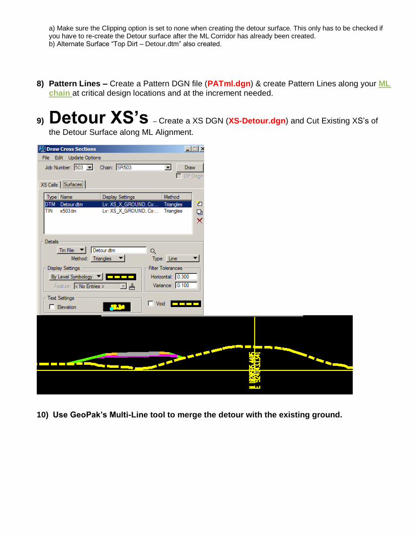
17) Tag Edit, delete the left ground components, and Drag & Drop the following Temporary Slope End Condition. It’s set by default to 2:1 but you can change by filling in the Parametric
Constraint of “Fill Temp Slope”.
18) Tag Tools – Target Aliasing which allows you to target the Detour Corridor (while traffic is on the detour.)
19) Parametric Constraints
Fill in any needed.
20) Process/Review Sections. Since the Detour Corridor was added as a Target Alias it is now being
displayed and it is being intersected by the temporary slope.

21) Create your ML Surface.
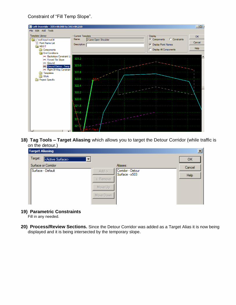
Make sure clipping options if off.
22) ML X-Sections (With Temp. Slope)
Enter XS-ML.DGN and cut X-sections.
23) Run EW to calculate your ML EW with a Temp. Slope.
24) Copy XS-ML.dgn to XS-detour-removal.dgn.
25) Use GeoPak’s Multi-Line tool to merge the detour with the existing ground.

Note: Levels in highlighted row are XS_P_FINISHED_GRADE, XS_P_SHOULDER, XS_P_GROUND.
26) Delete all elements except the XS_M_MULTI & then change the XS_M_MULTI elements to level XS_X_GROUND. This file will be used to place your Detour Removal in.
27) Create Detour Removal Corridor
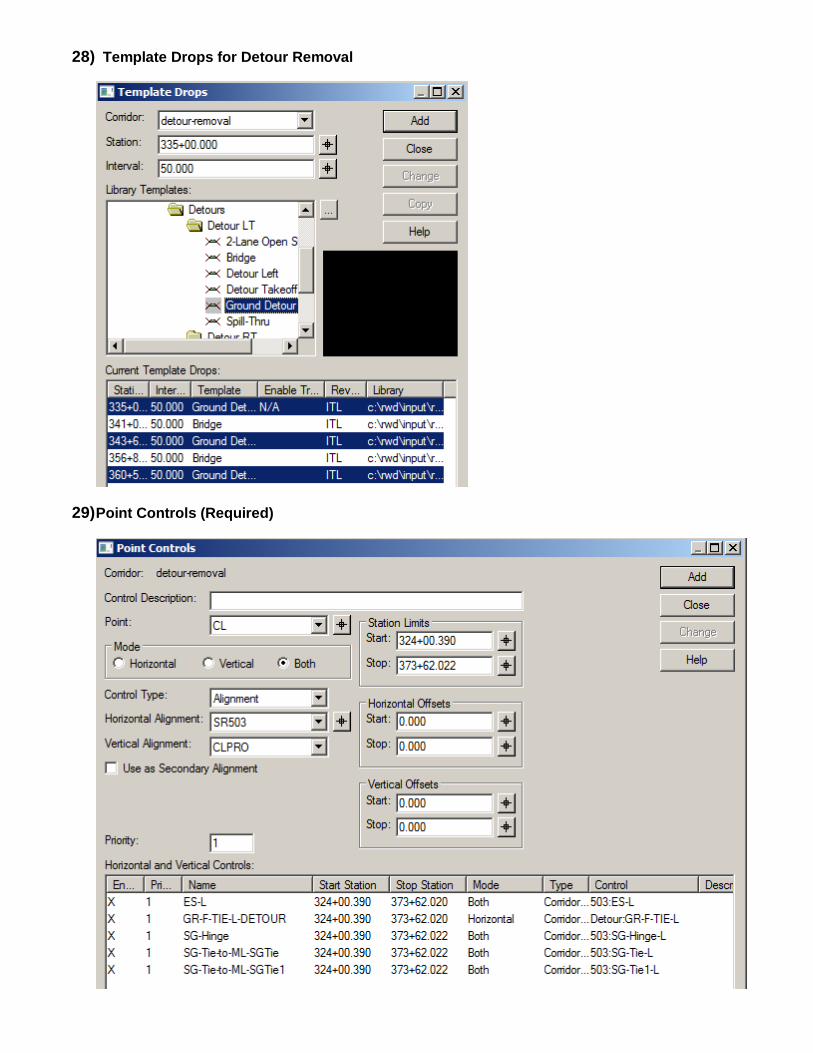
28) Template Drops for Detour Removal
29) Point Controls (Required)

30) Modify Parametric Constraints if needed.
31) Create Surface
Notes: a) Top Dirt – Detour Removal DTM also created. b) Make sure clipping options are set to none.

32) Cut Detour Removal Sections
Enter your XS-ML-Detour-Removal DGN file:
Example of Detour removal to natural ground.
33) Run EW for Detour Removal.
XS Sheet Layout
34) Enter XS-ML.DGN & reference XS-Detour & XS-Detour Removal. Lay out & turn on Nested References.