
One Stop Doc Renal and Urinary System and Electrolyte - Bakalis, Spyros, Stamoulos, Panos

COMPDYN 2015
5th ECCOMAS Thematic Conference on
Computational Methods in Structural Dynamics and Earthquake Engineering M. Papadrakakis, V. Papadopoulos, V. Plevris (eds.)
Crete Island, Greece, 25–27 May 2015
SURROGATE MODELLING OF LIQUID STORAGE TANKS FOR
SEISMIC PERFORMANCE DESIGN AND ASSESSMENT
Konstantinos Bakalis1, Michalis Fragiadakis2, and Dimitrios Vamvatsikos3
1 National Technical University of Athens
Institute of Steel Structures
Zografou Campus, 9 Iroon Polytechneiou str, 15780 Zografou, Athens, Greece
e-mail: [email protected]
2 National Technical University of Athens
Laboratory for Earthquake Engineering
Zografou Campus, 9 Iroon Polytechneiou str, 15780 Zografou, Athens, Greece
e-mail: [email protected]
3 National Technical University of Athens
Institute of Steel Structures
Zografou Campus, 9 Iroon Polytechneiou str, 15780 Zografou, Athens, Greece
e-mail: [email protected]
Keywords: Instructions, ECCOMAS Thematic Conference, Structural Dynamics, Earthquake
Engineering, Proceedings.
Abstract. The finite element method (FEM) is often employed to create detailed models for the
seismic assessment and design of liquid storage tanks. This comprehensive approach offers
accuracy, which is counter-balanced however by its computational inefficiency, especially for
the case of large-scale engineering problems. Regardless of the continuous evolution of com-
puter technology, surrogate models are necessary when such problems of engineering practice
are encountered. This study, attempts to develop an appropriate surrogate modelling approach,
tailored for the design and seismic risk assessment of liquid storage tanks. A formulation that
disregards fluid-structure-interaction is employed in view of providing a reasonable compro-
mise between modelling complexity and error. At the same time, a simplified methodology
based on nonlinear static procedures is proposed for the assessment of atmospheric tanks. The
comparison with Incremental Dynamic Analysis reveals a reasonable, yet conservative in some
cases, match for the damage states considered, thus offering an alternative methodology that
may easily be incorporated within code-based provisions.

Konstantinos Bakalis, Michalis Fragiadakis and Dimitrios Vamvatsikos
1 INTRODUCTION
Large-capacity cylindrical tanks are widely used to store a variety of liquids, such as petro-
leum and liquefied natural gas. The seismic risk of such industrial facilities is considerably
higher compared to ordinary structures, since the damage induced by a strong ground motion
may trigger uncontrollable consequences, not only on the actual facility but also on the envi-
ronment. Recent earthquakes, e.g., Kocaeli (1999) and Tohoku (2011), have shown that heavy
damage on tanks may lead to temporary loss of essential facilities, usually followed by leakage
and/or fire. In order to meet a desired level of safety, Performance-Based-Earthquake-Engi-
neering (PBEE) concepts can be employed to account for any potential sources of uncertainty.
However, recent codes of practice have not fully adopted the PBEE concept, and its application
to industrial facilities is limited to simple code provisions.
2 PROBLEM DEFINITION
Recent earthquakes have highlighted the need for innovative engineering concepts in order
to mitigate the devastating consequences following a strong ground motion. Although extensive
research takes place to date, earthquakes remain a major threat to the community both from a
social and a financial point of view. The PBEE concept forms the state-of-the-art approach for
evaluating the seismic risk, and should also be extended to critical infrastructure, such as the
liquid storage tanks found in industrial complexes. Various approaches serve under this frame-
work, ranging from simplified deterministic to comprehensive probabilistic. In the latter case,
the structural model adopted constitutes a key parameter for the successful performance evalu-
ation, due to the computational time required during the analysis. This remark is highlighted
for the case of atmospheric liquid storage tanks, where the simulation of the fluid-structure-
interaction may result in complex finite element models (FEM) that require a considerable
amount of time even for a single dynamic analysis [1]. Similar studies have developed numer-
ical approximations for the contained liquid [2,3], in an attempt to minimise the estimated com-
putational time. Although the aforementioned FEM-based procedures may be able to capture
complex modes of failure (e.g. local buckling), their suitability within a probabilistic framework
may become computationally prohibitive. Still, at least two studies have attempted to develop
simplified simulation techniques that blend efficiency and accuracy. Malhotra and Veletsos [4–
6] presented a simplified model for the two-dimensional (2D) analysis of liquid storage tanks,
while Cortes et al. [7] developed a model based on rigid beams and equivalent springs that can
be used for rapid dynamic analysis. Still, neither of the two models can be easily applied out-
of-the-box with commercial software: The first approach is based on custom-made analysis
software, while the second needs to be calibrated with a detailed finite element model (origi-
nally taken from the NZEE standards [8] by the authors).
3 MODELLING OF LIQUID STORAGE TANKS
The response of liquid storage tanks can be idealised using a two-degree-of-freedom (2DOF)
system, where the two masses (impulsive and convective) are considered decoupled [9–11].
The geometric and modal characteristics of the hydrodynamic problem are determined using
equivalent parameters for the impulsive and convective masses. For the purpose of this study,
the recommendations of Eurocode 8 [12] are adopted featuring Part 4 [13], where the design of
tanks is discussed in detail. Under the assumption that the impulsive pressure is acting on the
tank walls only, estimates for parameters such as the natural period coefficients (Ci and Cc), the
masses (mi and mc) and the effective height components (hi and hc) are obtained. Subscripts “i”
and “c” are used to denote “impulsive” and “convective” respectively. Previous studies have
shown that the contribution of the convective mass to the overall response of the structure can

Konstantinos Bakalis, Michalis Fragiadakis and Dimitrios Vamvatsikos
be ignored, as the impulsive mass is held responsible for the majority of the damage that tanks
suffer during a strong ground motion event [2,14].
A simplified modelling methodology for liquid storage tanks was recently proposed by Ba-
kalis et al. [15]. The surrogate modelling approach offers a compromise between computational
efficiency and accuracy for the nonlinear static or dynamic analysis. It is based on the work of
Malhotra and Veletsos [6] for liquid storage systems, where the uplifting mechanism of unan-
chored tanks is modelled analytically. According to the modelling procedure adopted the base
plate is divided into an even number of strips and one of them is subjected to an incremental
uplifting static load (V) in order to determine the associated resistance (Figure 1). The strip
model consists of force-based fibre beam column elements with element length equal to ap-
proximately 15 times the base plate thickness, tb. A uniaxial elastoplastic material is assigned
to the fibres in order to capture the inelastic behaviour of the base plate during uplift. Geometric
nonlinearities are taken into account through the co-rotational formulation. The foundation of
the tank is modelled using Winkler springs to account for the soil (or concrete slab) stiffness
beneath the plate. The Winkler springs are also assigned an elastic-no-tension material which
is suitable for the simulation of the base plate uplift. The base plate itself is modelled using
rigid beams that are supported on elastic multilinear springs. The latter simulate the nonlinear
uplifting resistance for each of the ‘N’ beam-spokes, representing equal-area sectors of the cir-
cular base plate. One may notice that the convective component of the fluid is not considered
in the model. This decision is twofold. Obviously, the contribution of the long-period convec-
tive component to the rigid-impulsive response of a broad tank may be deemed negligible [2].
That essentially provides a single rather than a double degree-of-freedom (DOF) system, the
efficiency of which can only be appreciated within a probabilistic framework. As a result, the
impulsive mass (mi) of the system is connected to the base using the elastic element shown in
Figure 2(a). The deflected shape shown in Figure 2(b) presents the uplifting mechanism of the
tank, where the base shear (Vb) induces a certain amount of uplift (w) on the beam-spokes of
the model. This mechanism offers the ability to estimate all major modes of failure, when they
are expressed as a function of uplift. Sloshing response on the other hand is only affected by
parameters such as the convective mass of the fluid and the available freeboard, and may be
calculated though a simple response spectrum analysis for the convective component, following
the Eurocode 8 [13] provisions.

Konstantinos Bakalis, Michalis Fragiadakis and Dimitrios Vamvatsikos
Figure 1: Strip model explained.
Figure 2: (a) Tank model and (b) its deflected shape.
3.1 Case Study
As a case study the liquid storage tank with the following geometric characteristics is
adopted. The tank considered has a radius (R) equal to 13.9m and a total height (ht) of 16.5m.
The bottom course wall (tw) is 17.7mm thick, while the corresponding base plate (tb) and annular
ring (ta) thickness are 6.4mm and 8.0mm, respectively. The fluid stored in the tank is assumed
to reach the maximum allowable fluid height of hf=14m, resulting to a ‘fluid height over radius’
ratio (hf/R) equal to 1.01. The properties of the liquid storage system adopted are summarised
on Table 1.

Konstantinos Bakalis, Michalis Fragiadakis and Dimitrios Vamvatsikos
Table 1. Properties of the tank examined.
Variable description Notation (units) Numerical values
Tank properties
Radius Rt (m) 13.9
Height ht (m) 16.5
Wall thickness per course tw (mm) 17.7/15.7/13.7/11.7/9.7/7.8/6.4/6.4/6.4
Base plate thickness tb (mm) 6.4
Annular ring thickness ta (mm) 8.0
Roof mass mr (ton) 35
Yield strength fy (MPa) 235
Steel Young’s Modulus Es (GPa) 210
Fluid properties Height hf (m) 14.0
Density pf (kg/m3) 1000
3.2 Validation
Figure 3 presents a comparison of the overturning moment obtained with our model and with
the detailed finite element model of Vathi et al. [2]. Good agreement between the two curves is
observed, despite the discrepancies found in the post yield zone. The modelling procedure de-
veloped herein presents a practically perfect match close to the yield point, although it seems
to underestimate the response of the unanchored tank for larger deformations. In all, the mod-
elling procedure adopted provides a good match to the FEM solution, as the differences found
do not exceed 15%.
Figure 3. Base plate rotational resistance.
4 PERFORMANCE OBJECTIVES
Field investigations after major earthquakes have revealed a variety of failure modes on at-
mospheric tanks. They may be summarised to shell buckling, base sliding and sloshing damage
to the upper tank shell and roof. EC8-part 4 [13] provides special provisions for these modes of
failure, as shown by Vathi et al. [2]. For instance, when partial uplift is allowed, either for
design purposes or due to poor detailing of the anchors, the rotation of the plastic hinge devel-
oped on the base plate of the tank should not exceed a certain rotational capacity. Moreover,
the excitation of the long period convective mass may cause sloshing of the contained liquid,

Konstantinos Bakalis, Michalis Fragiadakis and Dimitrios Vamvatsikos
which can in turn damage the upper parts of the tank (roof, upper wall course). During strong
ground motion events, hydrostatic and hydrodynamic effects may lead to high internal pressure
on the tank walls. Overturning for those thin shell structures is resisted by compressive merid-
ional stresses on the wall. Although high pressure may increase the capacity against buckling
by introducing high hoop stress, local yielding may trigger an elastic-plastic buckling failure
around the lower course of the tank’s perimeter, known as the “Elephant’s Foot Buckling”.
The most damaging failure modes are mainly associated with plate/shell rupture, as they
may result in loss of the contained liquid. Rupturing either the bottom layers of the tank wall or
the base plate is expected to trigger uncontrolled loss of the stored material, with all the associ-
ated consequences considered. Recently, Bakalis et al. [16] developed a performance-based
assessment methodology for atmospheric steel liquid storage tanks. The PBEE framework con-
siders three damage states of increasing severity, namely minor (DS1), severe without leakage
(DS2) and loss of containment (DS3). Although this classification may seem reasonable for
roughly understanding the extent of damage, the accurate assessment of loss may become tricky
as, for example, the different mechanisms involved in a single damage state may be associated
with varying degrees of component damage. For instance, the sloshing height response repre-
sents relatively easy-to-repair damage at the top of the tank, compared to an exceedance of a
plastic rotation limit at the base. Thus, it becomes more informative to also classify damage
based on the actual component that has failed. Figure 4 presents the associated failure modes
on the median Incremental Dynamic Analysis (IDA) curve [17] for the unanchored liquid stor-
age tank considered. The FEMA P695 [18] far field ground motion set is used for the nonlinear
dynamic analysis. The base uplift is adopted as one of the Engineering Demand Parameters
(EDP) and the impulsive period spectral acceleration Sa(Timp) or the peak ground acceleration
PGA (similar due to low Timp) are employed as suitable Intensity Measures (IM) that adequately
capture the response of a liquid storage system. It is evident that a component-based classifica-
tion of damage is quite informative, where the upper course of the tank (SL=sloshing), its lower
course (EFB), the base plate (θpl=plastic rotation), and the anchors (AN=yielding/fracture of
anchors) are individually examined. Failure modes such as buckling and plastic rotation are
revealed during the nonlinear time-history analysis. Sloshing damage at the top of the tank wall
is also considered. Still, as shown in Figure 4, this may only appear at excessive spectral accel-
eration values for large tanks due to the ultra-long convective period (Tcon).
Figure 4: Single record and median IDA curves for the unanchored tank examined. Sloshing damage appears
well beyond the limits of the graph.

Konstantinos Bakalis, Michalis Fragiadakis and Dimitrios Vamvatsikos
The local performance objectives summarised in Table 2 may indeed offer a comprehensive
procedure for understanding the extent of damage on a liquid storage unit, even offering the
potential for assigning detailed repair cost estimates. However, it may often be the case that a
global classification is required, suitable for characterising one or more tanks without specific
reference to the component that has been damaged. In that sense, DS1 represents minor damage
induced by a sloshing wave height of the contained liquid equal to the freeboard. DS2 refers to
severe damage at any component of the tank without leakage, where the exceedance of either a
sloshing wave height equal to 1.4 times the available freeboard or a plastic rotation of 0.2 rad
at the base plate triggers the damage state violation. DS3, finally, provides information on the
loss of containment through the exceedance of either the axial EFB capacity (NEFB) or the base
plate plastic rotation of 0.4 rad. As far as anchored systems are concerned, the yielding of the
anchors is considered for DS1, while the fracture of the connection for DS2. Global perfor-
mance objectives are presented on Table 3.
Figure 5: Global versus Local performance objectives for unanchored tanks.
Table 2: Local performance objectives.
Local DSi DS Capacities
DS1SL freeboard
DS1AN Anchorage yielding
DS2SL 1.4* freeboard
DS2AN Anchorage fracture
DS2θpl 0.2rad
DS3θpl 0.4rad
DS3EFB EFB strength

Konstantinos Bakalis, Michalis Fragiadakis and Dimitrios Vamvatsikos
Table 3: Global performance objectives
Tank Description Global (DSi) DS Capacities
Unanchored
DS1 DS1SL
DS2 DS2SL or DS2θpl
DS3 DS3θpl or DS3EFB
Anchored
DS1 DS1SL or DS1AN
DS2 DS2SL or DS2AN or DS2θpl
DS3 DS3θpl or DS3EFB
5 SIMPLIFIED INELASTIC RESPONSE FOR LIQUID STORAGE TANKS
Performance objectives may be well defined, however, their application within a code-based
methodology is still out of the box without the enforcement of nonlinear dynamic analysis.
From the early days of earthquake engineering [19] till the development of more sophisticated
methods [20–22], several research efforts exist for the prediction of inelastic response of struc-
tures. In spite of the miscellaneous approaches developed to date, there is common ground re-
lated to the translation of complex engineering concepts to simpler solutions that are more
appropriate for practicing engineers. In that sense, the Static Pushover analysis (SPO) plays an
important role in the assessment as well as the design of structures, where the well-known re-
duction factor (R)–ductility (μ)–period (T) relationship is required to determine the nonlinear
response of the equivalent SDOF oscillator. Such relationships are available for a variety of
structural systems (see Ruiz-Garcia and Miranda [21] for elastoplastic systems, Vamvatsikos
and Cornell [20] for oscillators with complex quadrilinear backbones). Malhotra and Veletsos
[6] have already shown that liquid storage tanks develop a nonlinear-elastic response with post-
yield hardening behaviour. Unfortunately, to the authors’ knowledge, such R-μ-T relationships
are not available in the existing literature, while Malhotra and Veletsos chose to use instead an
equivalent linearization technique that was also calibrated for elastoplastic systems. Left alone
with an ‘accuracy versus rapidness’ dilemma, the generation of new relationships that corre-
spond to the system examined is preferred over an obscure approximation that is based on ex-
isting R-μ-T relationships.
5.1 Fitting the hardening branch
A SDOF model with a bilinear backbone and a hardening ratio ah=1% is used to simulate
the response for a wide range of periods (0.1-1sec). A series of Incremental Dynamic Analyses
is performed for the given periods in order to form a set of data that will allow the fitting of the
hardening branch response. A pattern in log-space is adopted for the regression of the μ|R set
of data, as shown in Eq. (1). A pattern in the form of Eq. (2) is adopted for the regression of the
Eq. (1) coefficients (βix%) versus the system period. The entire fitting procedure is presented
below, where Figure 6 depicts the IDA curves and Figure 7 the Eq. (1) coefficient fits. Table 4
summarises the results of the fitting procedure.
5.1
%,2%,1%,0% lnlnln RR xxxx (1)
)/1(,3,2,1, TbTbbβ x%x%x%x%i (2)

Konstantinos Bakalis, Michalis Fragiadakis and Dimitrios Vamvatsikos
Figure 6. Strength reduction factor versus median ductility for T=0.1–1sec.
Figure 7: Regression on the Eq. (1) coefficients.
Table 4: Coefficients and functions for the IDA hardening branch fit.
bix% for β0,x% bix% for β1,x% bix% for β2,x%
hardening 16% 50% 84% 16% 50% 84% 16% 50% 84%
1 0.1056 0.6032 0.9851 0.4134 -0.2010 -1.4072 0.3221 0.7521 2.0113
T 0.0551 -0.3320 -0.6725 0.3290 0.9319 2.6714 -0.26667 -0.5504 -1.8568
1/T -0.0354 -0.0868 -0.0979 0.4275 0.7613 1.3283 -0.1659 -0.3598 -0.8404
6 FRAGILITY CURVES BASED ON STATIC PUSHOVER ANALYSIS
Several methodologies for estimating fragility curves have been proposed based on nonlin-
ear static procedures. The Static Pushover analysis is often employed to evaluate the system
performance in view of the simplicity offered to practicing engineers. Despite the approximat-
ing nature of the method, there is a major drawback related to record-to-record variability which
Konstantinos Bakalis, Michalis Fragiadakis and Dimitrios Vamvatsikos
is in turn propagated to the seismic fragility estimation. Thus, an inherently probabilistic prob-
lem is treated in a deterministic way, simply due to pushover analysis. Using the aforemen-
tioned expressions, record-to-record variability can be incorporated explicitly, while limit-state
capacity uncertainties can also be included for a structural system that can adequately be ap-
proximated by a SDOF oscillator. The aforementioned procedure finds application for the case
of liquid storage tanks when a model similar to the one developed by Bakalis et al. [15,16] is
used. Following a Static Pushover analysis performed on the full tank model, a bilinear ideali-
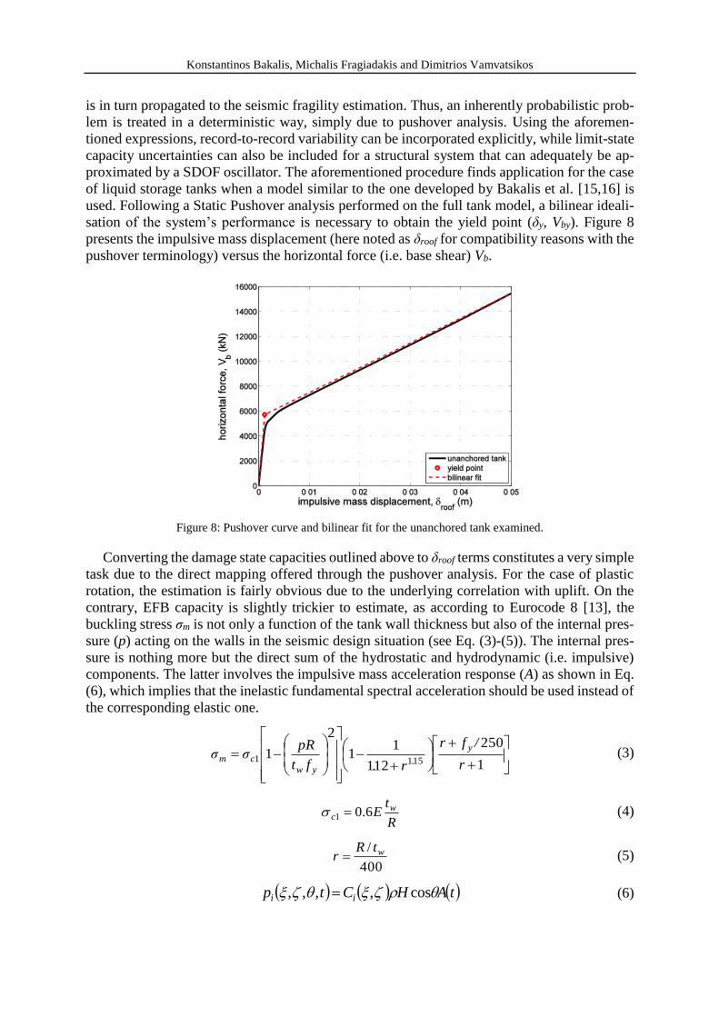
sation of the system’s performance is necessary to obtain the yield point (δy, Vby). Figure 8
presents the impulsive mass displacement (here noted as δroof for compatibility reasons with the
pushover terminology) versus the horizontal force (i.e. base shear) Vb.
Figure 8: Pushover curve and bilinear fit for the unanchored tank examined.
Converting the damage state capacities outlined above to δroof terms constitutes a very simple
task due to the direct mapping offered through the pushover analysis. For the case of plastic
rotation, the estimation is fairly obvious due to the underlying correlation with uplift. On the
contrary, EFB capacity is slightly trickier to estimate, as according to Eurocode 8 [13], the
buckling stress σm is not only a function of the tank wall thickness but also of the internal pres-
sure (p) acting on the walls in the seismic design situation (see Eq. (3)-(5)). The internal pres-
sure is nothing more but the direct sum of the hydrostatic and hydrodynamic (i.e. impulsive)
components. The latter involves the impulsive mass acceleration response (A) as shown in Eq.
(6), which implies that the inelastic fundamental spectral acceleration should be used instead of
the corresponding elastic one.
1
250
121
11
2
11511
r
/fr
r.ft
pRσσ
y
.yw
cm (3)
R
tE w
c 6.01 (4)
400
/ wtRr (5)
tAHCtp ii cos,,,, (6)

Konstantinos Bakalis, Michalis Fragiadakis and Dimitrios Vamvatsikos
The bilinear approximation adopted allows decoupling of the elastic and inelastic regions, when
the corresponding stiffness (kel, kh) is considered. Simply put, at the time of maximum defor-
mation, the inertia force equals the maximum spring restoring force. If we let Sael and Sa
inel
denote the absolute spectral accelerations in elasticity and inelasticity, respectively, and Sdel,
Sdinel stand for the corresponding spectral displacements, then, equilibrium for an elastic system
would be expressed as:
ela
eldel mSSk (7)
leading to the well-known expression Sael = ω2∙Sd
el. Instead, the equilibrium of an inelastic
system would appear as
ineldhhy
inela
yineldhyel
inela
SaaS
SkkmS
12
(8)
that allows us to conveniently use the impulsive mass displacement (available from a pushover
analysis) to estimate the corresponding inelastic spectral acceleration that influences EFB fail-
ure. As far as sloshing damage is concerned, one may rush into the conclusion that an accurate
seismic fragility estimation is not possible using pushover analysis, due to the inherent decou-
pling between the impulsive and convective response. From a first point of view, this is a valid
comment as the pushover analysis fundamentally refers to the first-mode loading pattern only.
However, in view of providing an approximate solution for the derivation of fragility curves,
the median convective spectral acceleration Sa(Tcon, 0.5%) may be converted to Sa(Timp, 2%)
terms in order to allow for the corresponding limiting δroof displacement estimation. In our case,
the FEMA P695 far-field ground motion set [18] was used to derive the relationship between
the central (i.e. median) value of the impulsive and convective spectral accelerations. Although
one may follow the scaling procedure for a given set of records shown in Figure 9, in practice
the design spectrum could also be employed with the aid of a damping adjustment factor. Care
should be exercised though for long convective periods (i.e. Tcon>4 sec), as the spectral accel-
eration shape is not adequately captured through the corresponding design (uniform hazard)
spectrum, something that can also be said for accelerograms that have been excessively high-
pass filtered.
Figure 9: Single record and median spectra featuring the impulsive versus the convective component.

Konstantinos Bakalis, Michalis Fragiadakis and Dimitrios Vamvatsikos
With the limiting capacities defined, the associated impulsive spectral accelerations may be
estimated by inverting the well-known control node displacement response equation found in
FEMA 440 [23] (see Eq. (10)). The inelastic displacement ratio CR (also noted as C1 in FEMA
440) can be estimated though Eq. (9), where the limiting reduction factor is known from the
linear regression equation, for a given ductility. Unlike the majority of static pushover applica-
tions, the fundamental-mode participation factor (C0) is set equal to one, as the capacity curve
shown in Figure 8 is a product of a simple SDOF model. Similarly, the stiffness degradation
modifier (C2) is also equal to one due to the nonlinear elastic response of the liquid storage
system.
lim
limlim
RCR
(9)
20
lim
2
limlim 1112
CCCS
R
roofa
(10)
The seismic fragility estimation forms a very simple procedure within a probabilistic frame-
work, where the capacities are considered lognormally distributed around the corresponding
limiting median estimates. The probability that demand exceeds the median limit state capacity,
for a given earthquake intensity, may be calculated through the standard normal cumulative
distribution function Φ shown in Eq. (11). Following a power law approximation for the median
demand (valid for performance levels away from the global instability region) [24], the latter
can also be given in the form of Eq. (12), where 2limroof
and 2 are the median capacity and
demand dispersions, and b the slope corresponding to the power law equation (see Eq. (13)).
The FEMA P-58 [25] guidelines are recommended for the median capacity dispersion estima-
tion. The proposed strength (EFB), ductility (plastic rotation) and displacement-based (sloshing)
procedures are employed for the damage state dispersion estimation. Obviously, for the case
that relevant data is available, the corresponding dispersion should be used in view of providing
a rather smaller margin of error in the final fragility estimation. Demand dispersion on the other
hand should be calculated through the 16% and 84% R-μ fractiles, as shown in Eq. (14).
22
lim
lim
ˆlnˆln|
roof
roofaroof
a
SSDCP (11)
22
lim
lim
1
ˆlnˆln|
roofb
SSSDCP aa
a (12)
lim
lim
ln
ln
Rb
(13)
2
lnln lim16lim84 RR
(14)

Konstantinos Bakalis, Michalis Fragiadakis and Dimitrios Vamvatsikos
In order to accurately assess the seismic risk involved in liquid storage tanks, an inten-
sity measure that characterises the structural system’s response in an optimal manner must be
identified. There could be a lot of discussion regarding which intensity measure better repre-
sents the structural response during the seismic risk assessment procedure. Unfortunately, such
a discussion is not valid when the pushover analysis is used, as the fundamental-mode load-
pattern adopted mandates the use of the corresponding spectral acceleration. For the case of
liquid storage tanks that would be the impulsive mass spectral acceleration Sa(Timp).
Figure 10 presents the seismic fragility evaluation based on the simplified procedure
outlined above. Fragility curves are provided for all local damage states given in Table 2, and
a comparison with the IDA-based assessment procedure discussed by Bakalis et al. [16] is per-
formed in view of evaluating the proposed SPO-based methodology. It appears that fragility
curves are in good agreement for the sloshing and plastic rotation damage states, although minor
discrepancies exist throughout the intensity considered, that can be attributed to the fitting pro-
cedure of the cumulative distribution function. The Elephant’s Foot Buckling failure mode also
presents a good match for low to moderate seismic intensities. Discrepancies are noticed though
as the impulsive spectral acceleration is increased, where the response seems to be significantly
overestimated when the pushover analysis is employed. Although further research is necessary
to verify the results of Figure 10, the complexity of the EFB mode of failure as well as the
associated uncertainties is of an extent that cannot probably be captured through a SDOF model
pushover analysis. Still the seismic fragility product presents a rather conservative illustration
of the system’s performance, and hence its application within a code-based methodology could
be considered.
Figure 10: A comparison between IDA and SPO-based fragility curves for the local DS classification.
7 CONCLUSIONS
A surrogate, yet robust, beam element model has been presented for the analysis of liquid
storage tanks. Its accuracy in comparison with computationally expensive finite element models
make it appealing for design applications. Since the computational effort for a single nonlinear
response history analysis does not exceed a few seconds, one may realise that the applicability
of the SDOF model can be extended to a seismic risk assessment framework. Incremental Dy-
namic Analysis is employed for the identification of the most damaging failure modes. Local
as well as global damage states are defined, favouring the seismic risk assessment of either a

Konstantinos Bakalis, Michalis Fragiadakis and Dimitrios Vamvatsikos
single liquid storage system or an entire group of tanks, respectively. Following the damage
state definition, a simplified assessment methodology is presented based on static pushover
analysis, where the estimation of the corresponding limiting capacities is discussed in detail.
The evaluation of the pushover-based seismic risk assessment methodology is performed
through the extraction of fragility curves that correspond to all local damage states. The com-
parison with an IDA-based methodology shows the pushover to offer a conservative estimate
for the Elephant’s Foot Buckling damage state, but a reasonable agreement for the remaining
failure modes. The proposed assessment methodology is not intended to substitute well-tested
procedures based on nonlinear dynamic analysis. Instead, it attempts to form a simplified tech-
nique that may serve under a code-based framework the majority of practicing engineers.
REFERENCES
[1] Kilic S and Ozdemir Z. “Simulation of Sloshing Effects in Cylindrical Containers under
Seismic Loading.” Proceedings of the 6 LS-DYNA Anwenderforum, Frankenthal, 2007.
[2] Vathi M, Pappa P and Karamanos SA. “Seismic Response of Unanchored Liquid Storage
Tanks.” Proceedings of the ASME 2013 Pressure Vessels & Piping Division Conference,
Paris, France, 2013.
[3] Talaslidis DG, Manolis GD, Paraskevopoulos E, Panagiotopoulos C, Pelekasis N and
Tsamopoulos J. “Risk analysis of industrial structures under extreme transient loads.”
Soil Dynamics and Earthquake Engineering, Vol. 24, No.6, 2004, pp. 435–48.
[4] Malhotra PK and Veletsos AS. “Beam Model for Base‐ Uplifting Analysis of
Cylindrical Tanks.” Journal of Structural Engineering, Vol. 120, No.12, 1994, pp. 3471–
88.
[5] Malhotra PK and Veletsos AS. “Uplifting Analysis of Base Plates in Cylindrical Tanks.”
Journal of Structural Engineering, Vol. 120, No.12, 1994, pp. 3489–505.
[6] Malhotra PK and Veletsos AS. “Uplifting Response of Unanchored Liquid‐ Storage
Tanks.” Journal of Structural Engineering, Vol. 120, No.12, 1994, pp. 3525–47.
[7] Cortes G, Prinz GS, Nussbaumer A and Koller MG. “Cyclic Demand at the Shell-Bottom
Connection of Unanchored Steel Tanks.” 15th World Conference on Earthquake
Engineering, Lisboa, Portugal, 2012.
[8] NZEE. “Seismic Design of Storage Tanks.” New Zealand National Society for
Earthquake Engineering Wellington, New Zealand, 2009.
[9] Malhotra PK, Wenk T and Wieland M. “Simple Procedure for Seismic Analysis of
Liquid-Storage Tanks.” Structural Engineering International, Vol. 10, No.3, 2000, pp.
197–201.
[10] Priestley MJN, Wood JH and Davidson BJ. “Seismic Design of Storage Tanks.” Bulletin
of the New Zealand Society for Earthquake Engineering, Vol. 19, No.4, 1986, pp. 272–
84.
[11] Calvi GM and Nascimbene R. “Progettazione sismica dei serbatoi.” Progettare i gusci,
IUSS Press, 2011. p. 537–672.
[12] CEN. “Eurocode 8: Design Provisions Of Structures For Earthquake Resistance - Part 1:
General rules, seismic actions and rules for buildings, CEN, Brussels.” CEN [Comité
Européen de Normalisation], 2004.
[13] CEN. “Eurocode 8: Design of structures for earthquake resistance–Part 4: Silos, tanks
and pipelines.” European Committee for Standard. Brussels, 2006.
[14] Malhotra PK. “Seismic Response of Soil-Supported Unanchored Liquid-Storage Tanks.”
Journal of Structural Engineering, Vol. 123, No.4, 1997, pp. 440–50.
Konstantinos Bakalis, Michalis Fragiadakis and Dimitrios Vamvatsikos
[15] Bakalis K, Vamvatsikos D and Fragiadakis M. “Surrogate Modelling and Sensitivity
Analysis of Steel Liquid Storage Tanks.” 8th Hellenic National Conference of Steel
Structures, Tripoli, Greece, 2-4 October 2014, 2014.
[16] Bakalis K, Vamvatsikos D and Fragiadakis M. “Seismic Reliability Assessment of
Liquid Storage Tanks.” 2nd European Conference on Earthquake Engineering and
Seismology, Istanbul, Turkey, 24-29 August 2014, 2014.
[17] Vamvatsikos D and Cornell CA. “Incremental dynamic analysis.” Earthquake
Engineering & Structural Dynamics, Vol. 31, No.3, 2002, pp. 491–514.
[18] FEMA. “Quantification of Building Seismic Performance Factors.” FEMA P-695,
prepared by Applied Technology Council for Federal Emergency Management Agency,
Washington, D.C., 2009.
[19] Veletsos A and Newmark NM. “Effect of inelastic behavior on the response of simple
systems to earthquake motions.” Proceedings of the 2nd World Conference on
Earthquake Engineering, 1960. p. 895–912.
[20] Vamvatsikos D and Cornell CA. “Direct estimation of the seismic demand and capacity
of oscillators with multi-linear static pushovers through IDA.” Earthquake Engineering
and Structural Dynamics, Vol. 35, No.April 2004, 2006, pp. 1097–117.
[21] Ruiz-García J and Miranda E. “Probabilistic estimation of maximum inelastic
displacement demands for performance-based design.” Earthquake Engineering and
Structural Dynamics, Vol. 36, No.March, 2007, pp. 1235–54.
[22] Kreslin M and Fajfar P. “The extended N2 method taking into account higher mode
effects in elevation.” Earthquake Engineering and Structural Dynamics, Vol. 40, 2011,
pp. 1571–89.
[23] FEMA. “Improvement of Nonlinear Static Seismic Analysis Procedures.” FEMA 440,
prepared by the Applied Technology Council for the Federal Emergency Management
Agency, Washington D.C, 2005.
[24] Cornell CA, Jalayer F, Hamburger RO and Foutch D a. “Probabilistic Basis for 2000
SAC Federal Emergency Management Agency Steel Moment Frame Guidelines.”
Journal of Structural Engineering. 2002. p. 526–33.
[25] FEMA. “Seismic Performance Assessment of Buildings.” FEMA P-58, prepared by the
Applied Technology Council for the Federal Emergency Management Agency,
Washington D.C, 2012.