Surface Treatment Plan - California Public Utilities ...
17
AGENCY DRAFT Surface Treatment Plan West of Devers Transmission Line Upgrade Project Prepared for Southern California Edison May 2017 6 Hutton Centre Drive, Suite 700 Santa Ana, CA 92707
Transcript of Surface Treatment Plan - California Public Utilities ...

A G E N C Y D R A F T
Surface Treatment Plan
West of Devers Transmission Line Upgrade Project
Prepared for
Southern California Edison
May 2017
6 Hutton Centre Drive, Suite 700 Santa Ana, CA 92707
PR0213171152SCO
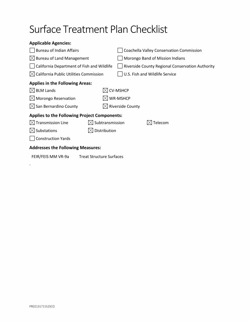
Surface Treatment Plan Checklist Applicable Agencies:
Bureau of Indian Affairs Coachella Valley Conservation Commission
Bureau of Land Management Morongo Band of Mission Indians
California Department of Fish and Wildlife Riverside County Regional Conservation Authority
California Public Utilities Commission U.S. Fish and Wildlife Service
Applies in the Following Areas: BLM Lands CV-MSHCP
Morongo Reservation WR-MSHCP
San Bernardino County Riverside County
Applies to the Following Project Components: Transmission Line Subtransmission Telecom
Substations Distribution
Construction Yards
Addresses the Following Measures:
FEIR/FEIS MM VR-9a Treat Structure Surfaces .

PR0213171152SCO III
Contents Section Page
Acronyms and Abbreviations .............................................................................................................. v
1 Introduction ....................................................................................................................... 1-1 1.1 Project Overview .............................................................................................................. 1-1 1.2 Project Location ............................................................................................................... 1-2 1.3 Lead Agencies .................................................................................................................. 1-2 1.4 Mitigation Measure ......................................................................................................... 1-3 1.5 Applicable Project Segments ........................................................................................... 1-3 1.6 Timing .............................................................................................................................. 1-4
2 Methods ............................................................................................................................. 2-1 2.1 Transmission Structures................................................................................................... 2-1 2.2 Subtransmission and Distribution .................................................................................... 2-1 2.3 Substation Equipment ..................................................................................................... 2-2 2.4 Telecommunication Equipment ....................................................................................... 2-2 2.5 Retaining Walls ................................................................................................................ 2-2 2.6 Maintenance of Surface Treatments ............................................................................... 2-2
3 Plan Approval ..................................................................................................................... 3-1
4 References .......................................................................................................................... 4-1
5 Revisions ............................................................................................................................ 5-1
Figures
2-1 Surface Finish Comparison
2-2 Simulated View of Lattice Steel Structures Constructed Using Dulled, Slightly Darkened Galvanized Steel
2-3 Simulated View of Tubular Steel Structures Constructed Using Dulled, Slightly Darkened Galvanized Steel

PR0213171152SCO V
Acronyms and Abbreviations BLM Bureau of Land Management
CAISO California Independent System Operator
CPUC California Public Utilities Commission
FEIR Final Environmental Impact Report
FEIS Final Environmental Impact Statement
kV kilovolt
LST lattice steel tower
LWSP lightweight steel pole
MM mitigation measure
Morongo Reservation Reservation Trust Lands of the Morongo Band of Mission Indians
Plan Surface Treatment Plan
Project West of Devers Upgrade Project
ROW right-of-way
SCE Southern California Edison
TSP tubular steel pole
WOD West of Devers
SECTION 1
PR0213171152SCO 1-1
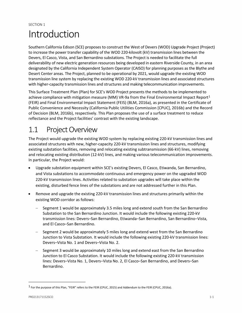
Introduction Southern California Edison (SCE) proposes to construct the West of Devers (WOD) Upgrade Project (Project) to increase the power transfer capability of the WOD 220-kilovolt (kV) transmission lines between the Devers, El Casco, Vista, and San Bernardino substations. The Project is needed to facilitate the full deliverability of new electric generation resources being developed in eastern Riverside County, in an area designated by the California Independent System Operator (CAISO) for planning purposes as the Blythe and Desert Center areas. The Project, planned to be operational by 2021, would upgrade the existing WOD transmission line system by replacing the existing WOD 220-kV transmission lines and associated structures with higher-capacity transmission lines and structures and making telecommunication improvements.
This Surface Treatment Plan (Plan) for SCE’s WOD Project presents the methods to be implemented to achieve compliance with mitigation measure (MM) VR-9a from the Final Environmental Impact Report1 (FEIR) and Final Environmental Impact Statement (FEIS) (BLM, 2016a), as presented in the Certificate of Public Convenience and Necessity (California Public Utilities Commission [CPUC], 2016b) and the Record of Decision (BLM, 2016b), respectively. This Plan proposes the use of a surface treatment to reduce reflectance and the Project facilities’ contrast with the existing landscape.
1.1 Project Overview The Project would upgrade the existing WOD system by replacing existing 220-kV transmission lines and associated structures with new, higher-capacity 220-kV transmission lines and structures, modifying existing substation facilities, removing and relocating existing subtransmission (66-kV) lines, removing and relocating existing distribution (12-kV) lines, and making various telecommunication improvements. In particular, the Project would:
• Upgrade substation equipment within SCE’s existing Devers, El Casco, Etiwanda, San Bernardino, and Vista substations to accommodate continuous and emergency power on the upgraded WOD 220-kV transmission lines. Activities related to substation upgrades will take place within the existing, disturbed fence lines of the substations and are not addressed further in this Plan.
• Remove and upgrade the existing 220-kV transmission lines and structures primarily within the existing WOD corridor as follows:
− Segment 1 would be approximately 3.5 miles long and extend south from the San Bernardino Substation to the San Bernardino Junction. It would include the following existing 220-kV transmission lines: Devers–San Bernardino, Etiwanda–San Bernardino, San Bernardino–Vista, and El Casco–San Bernardino.
− Segment 2 would be approximately 5 miles long and extend west from the San Bernardino Junction to Vista Substation. It would include the following existing 220-kV transmission lines: Devers–Vista No. 1 and Devers–Vista No. 2.
− Segment 3 would be approximately 10 miles long and extend east from the San Bernardino Junction to El Casco Substation. It would include the following existing 220-kV transmission lines: Devers–Vista No. 1, Devers–Vista No. 2, El Casco–San Bernardino, and Devers–San Bernardino.
1 For the purpose of this Plan, “FEIR” refers to the FEIR (CPUC, 2015) and Addendum to the FEIR (CPUC, 2016a).
SECTION 1 – INTRODUCTION
1-2 PR0213171152SCO
− Segment 4 would be approximately 12 miles long and extend east from the El Casco Substation to San Gorgonio Avenue in the City of Banning. It would include the following existing 220-kV transmission lines: Devers–Vista No. 1, Devers–Vista No. 2, Devers–El Casco, and Devers–San Bernardino.
− Segment 5 would be approximately 9 miles long and extend east from San Gorgonio Avenue in the City of Banning to the eastern limit of the Reservation Trust Lands of the Morongo Band of Mission Indians (Morongo Reservation) at Rushmore Avenue. It would include the following existing 220-kV transmission lines: Devers–Vista No. 1, Devers–Vista No. 2, Devers–El Casco, and Devers–San Bernardino.
− Segment 6 would be approximately 8 miles long and extend east from the eastern boundary of the Morongo Reservation to Devers Substation. It would include the following existing 220-kV transmission lines: Devers–Vista No. 1, Devers–Vista No. 2, Devers–El Casco, and Devers–San Bernardino.
• Remove a portion (approximately 2 miles) of the existing San Bernardino–Redlands–Timoteo and San Bernardino–Redlands–Tennessee 66-kV Subtransmission Lines from within the existing WOD right-of-way (ROW) and reconstruct as follows:
− The relocated San Bernardino–Redlands–Timoteo 66-kV Subtransmission Line would be approximately 2 miles long and would reconnect to the San Bernardino–Redlands–Timoteo 66-kV Subtransmission Line inside Timoteo–Substation.
− The relocated San Bernardino–Redlands–Tennessee 66-kV Subtransmission Line would be approximately 3.5 miles long and would reconnect to the San Bernardino–Redlands–Tennessee 66-kV Subtransmission Line at Barton Road.
• Remove a portion of the existing Dental and Intern 12-kV distribution circuits within the WOD ROW and relocate the circuits as follows:
− The relocated Dental 12-kV Distribution Circuit would be approximately 1.5 miles long and would reconnect to the existing Dental 12-kV circuit.
− The relocated Intern 12-kV Distribution Circuit would be approximately 2.25 miles long and would reconnect to the Intern 12-kV circuit.
• Install telecommunication lines and equipment for the protection, monitoring, and control of transmission lines and substation equipment.
1.2 Project Location The Project crosses the cities of Banning, Beaumont, Calimesa, Colton, Grand Terrace, Loma Linda, Palm Springs, Rancho Cucamonga, Redlands, San Bernardino, and Yucaipa, as well as unincorporated areas of Riverside and San Bernardino counties. The transmission corridor passes over Interstate 215 in San Bernardino County, as well as State Route (SR)-60, SR-79, SR-243, and SR-62 in Riverside County, and runs approximately parallel to the majority of the Interstate 10 corridor in both San Bernardino and Riverside counties.
1.3 Lead Agencies Lead agencies have discretionary approval over the Project and are responsible for this Plan. The CPUC is the state lead agency responsible for compliance with the California Environmental Quality Act. The Bureau of Land Management (BLM) is the federal lead agency responsible for compliance with National

SECTION 1 – INTRODUCTION
PR0213171152SCO 1-3
Environmental Policy Act. Identified materials or documentation will be provided to the CPUC and the BLM in accordance with the Project requirements.
1.4 Mitigation Measure This Plan addresses MM VR-9a from the FEIR and FEIS which states:
Treat structure surfaces. SCE shall treat the surfaces of all structures and new buildings visible to the public such that: a) their colors minimize visual contrast by blending with the characteristic landscape colors; b) their colors and finishes do not create excessive glare; and c) their colors and finishes are consistent with local policies and ordinances. The transmission structures and conductors shall be non-specular and non-reflective, and the insulators shall be non-reflective and non-refractive. SCE shall consider the use of special galvanizing treatments or post-manufacture application of chemical treatments (such as Natina Steel) to ensure that transmission structures are sufficiently dulled and non-reflective and are of the appropriate color to blend effectively with the surrounding landscape. SCE shall comply with CPUC and BLM requirements regarding appropriate surface treatments for Proposed Project elements.
SCE shall provide to the CPUC and BLM for review, a draft Surface Treatment Plan describing the application of colors and textures to all new facility structures, buildings, walls, fences, and components comprising all facilities to be constructed. The draft Surface Treatment Plan must explain how the design will reduce glare and minimize visual intrusion and contrast by blending the facilities with the landscape. The draft plan shall be submitted to CPUC and BLM at least 60 days prior to ordering the first structures that are to be color-treated during manufacture or prior to construction of any of the facility components, whichever comes first. If the BLM or CPUC notifies SCE that revisions to the plan are needed before the plan can be approved, within 30 days of receiving that notification, SCE shall prepare and submit for review and approval a revised plan. The draft Surface Treatment Plan shall include the following components and specifications.
• Specification, and 11” x 17” color simulations at life-size scale, of the treatment proposed for use on structures, including structures treated during manufacture.
• A list of each major structure, building, tower and/or pole, and fencing specifying the color(s) and finish(es) proposed for each (colors must be identified by name and by vendor brand or a universal designation).
• Two sets of brochures and/or color chips for each proposed color.
• A detailed schedule for completion of the treatment.
• A procedure to ensure proper treatment maintenance for the life of the Proposed Project.
• Until SCE receives notification of approval of the Surface Treatment Plan by the CPUC and BLM, SCE shall not specify to the vendors the treatment of any buildings or structures for manufacture and shall not perform the final treatment on any buildings or structures treated on site. Additionally, construction activities shall not start until approval of the plan from the CPUC and BLM has been received. Within 14 days following the completion of treatment on any facility component, SCE shall notify the CPUC and BLM that the component (e.g., structure or building) is ready for inspection.
1.5 Applicable Project Segments The Plan addresses structure surface treatment procedures required for facilities constructed across all Segments of the Project.

SECTION 1 – INTRODUCTION
1-4 PR0213171152SCO
1.6 Timing Per MM VR-9a, this Plan will be submitted to CPUC and BLM at least 60 days prior to ordering the tower steel, conductors, insulators, and retaining wall block that are to be treated during manufacture. If BLM or CPUC notifies SCE that revisions to the Plan are needed before the Plan can be approved, within 30 days of receiving that notification, SCE shall prepare and submit for review and approval a revised Plan. SCE will proceed with steel procurement after the Plan is approved. Because the methods proposed in this Plan would address surface treatments to be applied by the manufacturer, it applies prior to construction. For retaining wall block that may require treatment after construction to match the color of adjacent native surfaces, treatment may be performed during construction.
SECTION 2
PR0213171152SCO 2-1
Methods The following sections include a description of the methods by which SCE will treat the surfaces of structures visible to the public to minimize visual contrast and excessive glare. Because the Project involves upgrade of existing facilities, Project components on which new facilities will be constructed are generally limited to replacement transmission, subtransmission, distribution, and telecommunication lines. No new substations, reactors, series capacitors, or other facilities that would introduce potential visual contrasts have been proposed.
2.1 Transmission Structures MM VR-9a specifies that transmission structures and conductors shall be non-specular and non-reflective, and the insulators shall be non-reflective and non-refractive. It also specifies that SCE shall consider the use of special galvanizing treatments or, if necessary, post-manufacture application of chemical treatments (such as Natina Steel) to ensure that transmission structures are sufficiently dulled and non-reflective, and are of the appropriate color to blend effectively with the surrounding landscape. SCE considered three finish treatments (light-gray dulled galvanized, medium-gray dulled galvanized, and dark-gray dulled galvanized) for the transmission line structures—lattice steel towers (LSTs) and tubular steel poles (TSPs). The goal was to select a surface treatment that would blend into the landscape settings. In viewing darkened TSPs along recently built transmission lines in Southern California, it was apparent that the darker colors stand out against the existing landscape and provide more contrast than lighter-gray towers, which tend to blend into the background with distance. For this reason, SCE has determined that the best choice for blending the proposed transmission structures into the Project landscape is to specify that the galvanized steel used for the LSTs and TSPs be treated at the factory to produce a dulled light gray to avoid internal color contrasts and provide a color that minimizes contrast with the surroundings. A color sample and comparison are provided on Figure 2-1. Sample 1 represents the dulling and level of darkening that will be specified for the steel used to construct lattice steel and steel pole structures used for the Project. Sample 2 is galvanized steel that has been dulled to a very dark tone. Sample 3 represents galvanized steel that has not received any dulling or darkening treatment.
For all segments of the line, dulled, non-specular conductors will be used. The insulators specified will be made of a composite material with a dulled gray finish that will not have the reflective or refractive properties associated with glass insulators.
In addition to the small-scale steel color samples, simulations were also completed. Figure 2-2 is a simulation of a segment of the Project consisting of LSTs with the dulled, light-gray finish, non-specular conductors, and composite insulators with a dulled gray finish. Figure 2-3 depicts a segment of the line with TSPs that also have the dulled, light-gray finish as well as non-specular conductors, and composite insulators with a dulled gray finish.
2.2 Subtransmission and Distribution The subtransmission and distribution project components may include LSTs, TSPs, lightweight steel poles (LWSP), and/or wooden poles. Wooden poles are, by nature, non-reflective and do not contrast with the surrounding landscape. LSTs, TSPs, and LWSPs would be treated with a dull light-gray galvanization as described in Section 2.1.

2-2 PR0213171152SCO
SECTION 2 – METHODS
2.3 Substation Equipment The planned upgrades of the substation equipment at the Devers, El Casco, Etiwanda, San Bernardino, and Vista substations will entail replacing existing circuit breakers and disconnects with new equipment with the capacity to handle the increase in power related to the new lines. As is the case with the existing circuit breaker cabinets, the surfaces of the new circuit breaker cabinets will be similar to an American National Standards Institute 70 gray finish. The substation upgrades will not require construction of new buildings or modification of existing buildings. In addition, upgrades will not entail any changes to the fences around the perimeters of the substations. Because there will be no noticeable physical changes to the substations and no changes to the colors of the existing substation features, there is no need for additional surface treatment measures at the substations.
2.4 Telecommunication Equipment The Project includes installation of telecommunication lines and equipment for the protection, monitoring, and control of transmission lines and substation equipment. Most of the new telecommunication equipment will be located inside the existing telecommunication structures on the substation sites and will not be visible. The telecommunication lines will be thin, black insulated wires with low levels of visibility. The splice boxes that will be located on the structures that carry the telecommunication lines will be small and similar to American National Standards Institute 70 gray in color. Because these boxes are small and will have a dull, neutral-colored finish, no further surface treatment will be required.
2.5 Retaining Walls The Project includes a limited number of retaining walls along access roads and at tower sites. Because retaining walls will be constructed to control erosion, they will be constructed in areas with minimal vegetation (e.g., boulders, rocky slopes, erosional features). Two general types of retaining walls will be used: soldier pile walls and Hilfiker walls. The exposed face of soldier pile walls will be composed of galvanized metal “C” channels. The surfaces will be treated with special galvanizing treatments or post-manufacture application of chemical treatments (such as Natina Steel) after installation. The Hilfiker walls will be constructed using welded wire mesh with native backfill for most applications. The fill material will be selected to match the local terrain. One Hilfiker wall will incorporate the Eureka Reinforced Soil method, which is similar in concept and construction to the welded wire wall but includes the addition of precast full-height fascia panels. The panels will be painted after construction to match the surrounding environment.
2.6 Maintenance of Surface Treatments The tower steel, insulators, and conductors are expected to further dull over time and show less visual contrast. Maintenance is not expected to be required for these components maintain a dull finish throughout the lifespan of the tower. The colored concrete retaining wall blocks are also expected to maintain their finish throughout the life of the retaining walls and are not expected to require maintenance.
SCE will attempt to avoid treatment during or after tower construction (e.g., Natina) to limit the use of liquids that may be potentially hazardous to the environment. SCE does not anticipate using this method; however, it is referred to in this plan as a potential contingency should in-field treatment be necessary.

SECTION 3
PR0213171152SCO 3-1
Plan Approval This Plan has been prepared to address FEIR/FEIS MM VR-9a. SCE requests review and approval of this Plan from the CPUC and the BLM.

SECTION 4
EN1102161103MKE 4-1
References Bureau of Land Management (BLM). 2016a. Final Environmental Impact Statement Report - Southern California Edison’s West of Devers Upgrade Project. August.
Bureau of Land Management (BLM). 2016b. Record of Decision for the West of Devers Upgrade Project. BLM/CA/PL-2015/012+1793, DOI-BLM-CA-060-0015-0021, CACA-055285. December.
California Public Utilities Commission (CPUC). 2015. Final Environmental Impact Report (FEIR), Southern California Edison’s West of Devers Upgrade Project. SCH #2014051041. December. http://www.cpuc.ca.gov/environment/info/aspen/westofdevers/toc-feir.htm.
California Public Utilities Commission (CPUC). 2016a. Addendum to Final Environmental Impact Report, Southern California Edison’s West of Devers Upgrade Project. SCH #2014051041. April. http://www.cpuc.ca.gov/environment/info/aspen/westofdevers/feir_addendum.pdf.
California Public Utilities Commission (CPUC). 2016b. Decision Granting Certificate of Public Convenience and Necessity for the West of Devers Upgrade Project and Related Matter. August. http://docs.cpuc.ca.gov/PublishedDocs/Published/G000/M166/K441/166441910.pdf.

SECTION 5
EN1102161103MKE 5-1
Revisions Revisions made to standard text (black ink) should be noted below to document changes in requirements or SCE’s approach to this Surface Treatment Plan.
Date Description of Revision Contact

Figures

Sample 1Dulled and very slightly darkened treatment (preferred)
Figure 2-1.Surface Finish ComparisonSurface Treatment PlanSouthern California EdisonWest of Devers Upgrade Project
Sample 2Dark gray tone treatment
Sample 3Galvanized steel (no treatment)

Simulated view that depicts the appearance of a line segment with lattice steel structures constructed using dulled, slightly darkened galvanized steel.
Figure 2-2.Simulated View of Lattice Steel StructuresConstructed Using Dulled, Slightly DarkenedGalvanized SteelSurface Treatment PlanSouthern California EdisonWest of Devers Upgrade Project
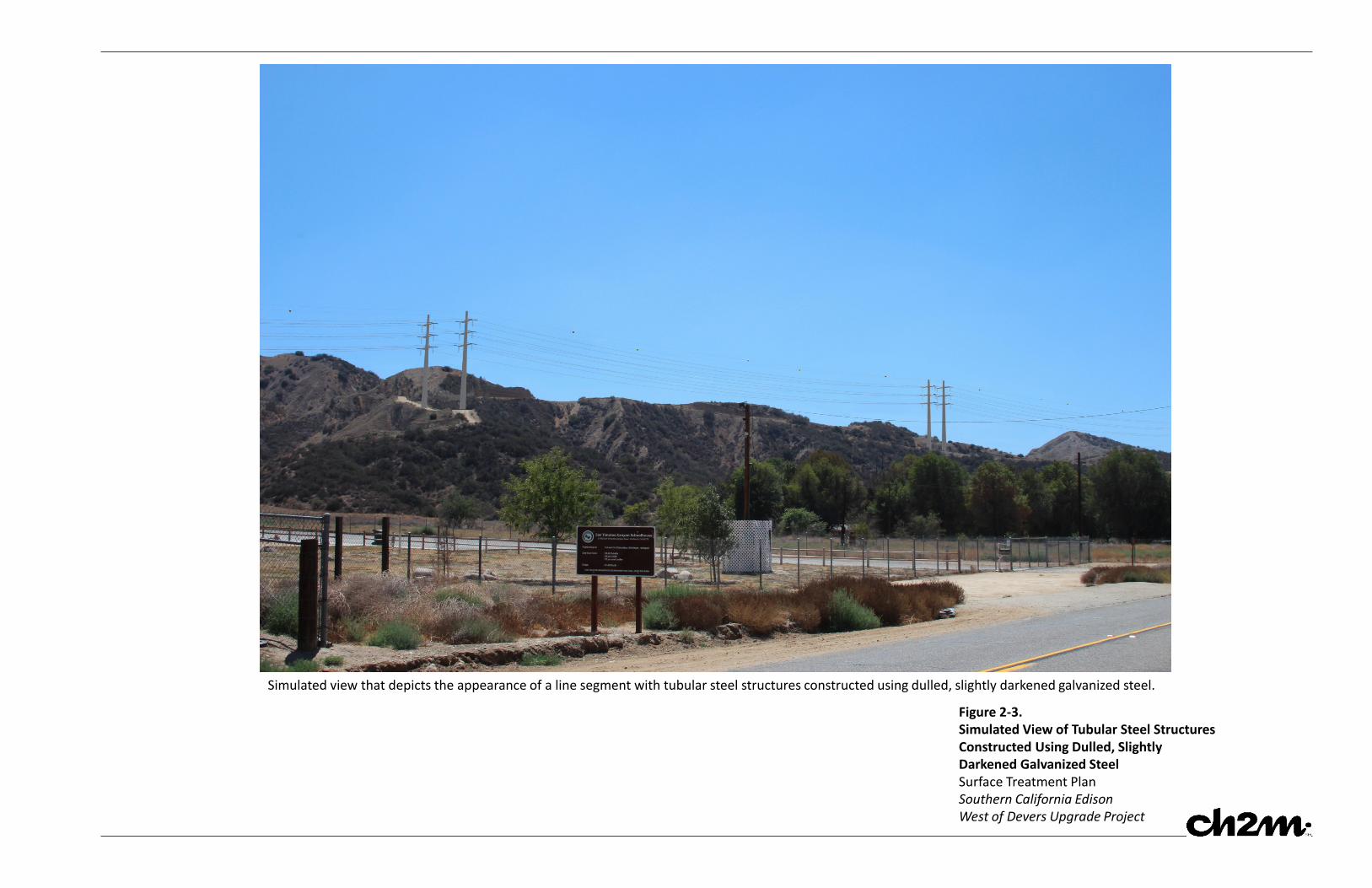
Simulated view that depicts the appearance of a line segment with tubular steel structures constructed using dulled, slightly darkened galvanized steel.
Figure 2-3.Simulated View of Tubular Steel StructuresConstructed Using Dulled, SlightlyDarkened Galvanized SteelSurface Treatment PlanSouthern California EdisonWest of Devers Upgrade Project