Surface-plasmon-resonance-like fiber-based sensor at terahertz frequencies
5
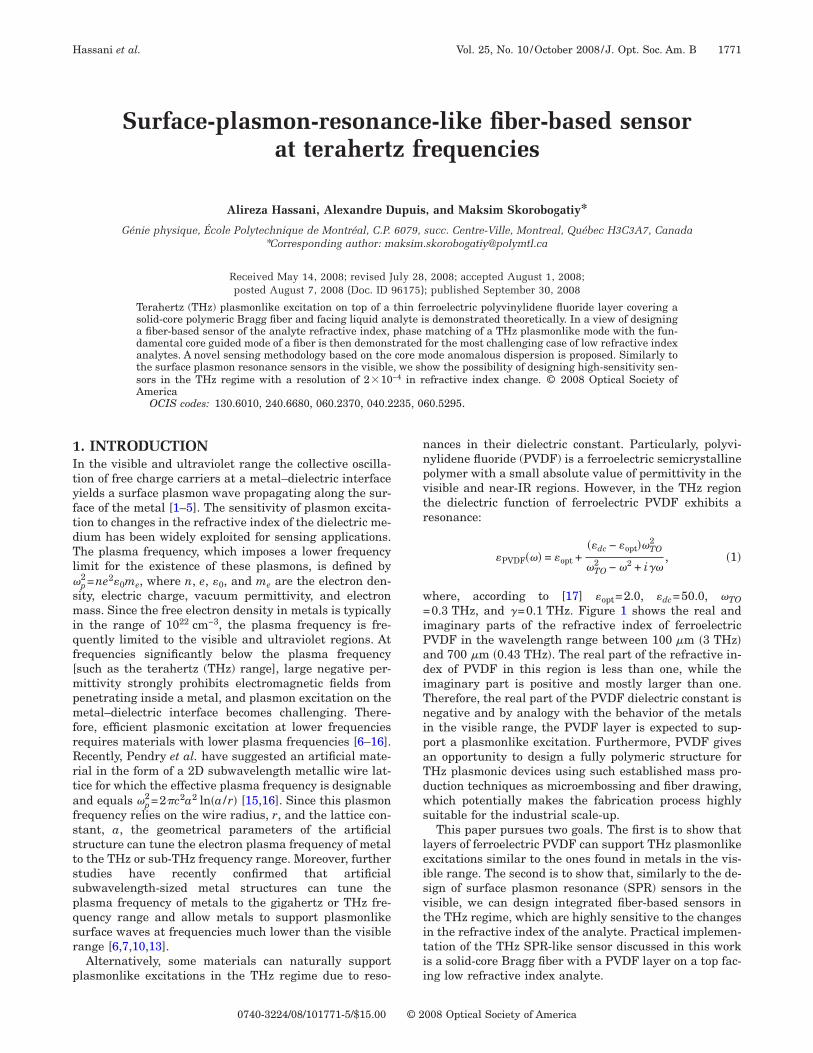
Surface-plasmon-resonance-like fiber-based sensor at terahertz frequencies Alireza Hassani, Alexandre Dupuis, and Maksim Skorobogatiy* Génie physique, École Polytechnique de Montréal, C.P. 6079, succ. Centre-Ville, Montreal, Québec H3C3A7, Canada * Corresponding author: [email protected] Received May 14, 2008; revised July 28, 2008; accepted August 1, 2008; posted August 7, 2008 (Doc. ID 96175); published September 30, 2008 Terahertz (THz) plasmonlike excitation on top of a thin ferroelectric polyvinylidene fluoride layer covering a solid-core polymeric Bragg fiber and facing liquid analyte is demonstrated theoretically. In a view of designing a fiber-based sensor of the analyte refractive index, phase matching of a THz plasmonlike mode with the fun- damental core guided mode of a fiber is then demonstrated for the most challenging case of low refractive index analytes. A novel sensing methodology based on the core mode anomalous dispersion is proposed. Similarly to the surface plasmon resonance sensors in the visible, we show the possibility of designing high-sensitivity sen- sors in the THz regime with a resolution of 2 10 -4 in refractive index change. © 2008 Optical Society of America OCIS codes: 130.6010, 240.6680, 060.2370, 040.2235, 060.5295. 1. INTRODUCTION In the visible and ultraviolet range the collective oscilla- tion of free charge carriers at a metal–dielectric interface yields a surface plasmon wave propagating along the sur- face of the metal [1–5]. The sensitivity of plasmon excita- tion to changes in the refractive index of the dielectric me- dium has been widely exploited for sensing applications. The plasma frequency, which imposes a lower frequency limit for the existence of these plasmons, is defined by p 2 = ne 2 0 m e , where n, e, 0 , and m e are the electron den- sity, electric charge, vacuum permittivity, and electron mass. Since the free electron density in metals is typically in the range of 10 22 cm -3 , the plasma frequency is fre- quently limited to the visible and ultraviolet regions. At frequencies significantly below the plasma frequency [such as the terahertz (THz) range], large negative per- mittivity strongly prohibits electromagnetic fields from penetrating inside a metal, and plasmon excitation on the metal–dielectric interface becomes challenging. There- fore, efficient plasmonic excitation at lower frequencies requires materials with lower plasma frequencies [6–16]. Recently, Pendry et al. have suggested an artificial mate- rial in the form of a 2D subwavelength metallic wire lat- tice for which the effective plasma frequency is designable and equals p 2 =2c 2 a 2 lna / r [15,16]. Since this plasmon frequency relies on the wire radius, r, and the lattice con- stant, a, the geometrical parameters of the artificial structure can tune the electron plasma frequency of metal to the THz or sub-THz frequency range. Moreover, further studies have recently confirmed that artificial subwavelength-sized metal structures can tune the plasma frequency of metals to the gigahertz or THz fre- quency range and allow metals to support plasmonlike surface waves at frequencies much lower than the visible range [6,7,10,13]. Alternatively, some materials can naturally support plasmonlike excitations in the THz regime due to reso- nances in their dielectric constant. Particularly, polyvi- nylidene fluoride (PVDF) is a ferroelectric semicrystalline polymer with a small absolute value of permittivity in the visible and near-IR regions. However, in the THz region the dielectric function of ferroelectric PVDF exhibits a resonance: PVDF = opt + dc - opt TO 2 TO 2 - 2 + i , 1 where, according to [17] opt = 2.0, dc = 50.0, TO =0.3 THz, and = 0.1 THz. Figure 1 shows the real and imaginary parts of the refractive index of ferroelectric PVDF in the wavelength range between 100 m 3 THz and 700 m 0.43 THz. The real part of the refractive in- dex of PVDF in this region is less than one, while the imaginary part is positive and mostly larger than one. Therefore, the real part of the PVDF dielectric constant is negative and by analogy with the behavior of the metals in the visible range, the PVDF layer is expected to sup- port a plasmonlike excitation. Furthermore, PVDF gives an opportunity to design a fully polymeric structure for THz plasmonic devices using such established mass pro- duction techniques as microembossing and fiber drawing, which potentially makes the fabrication process highly suitable for the industrial scale-up. This paper pursues two goals. The first is to show that layers of ferroelectric PVDF can support THz plasmonlike excitations similar to the ones found in metals in the vis- ible range. The second is to show that, similarly to the de- sign of surface plasmon resonance (SPR) sensors in the visible, we can design integrated fiber-based sensors in the THz regime, which are highly sensitive to the changes in the refractive index of the analyte. Practical implemen- tation of the THz SPR-like sensor discussed in this work is a solid-core Bragg fiber with a PVDF layer on a top fac- ing low refractive index analyte. Hassani et al. Vol. 25, No. 10/ October 2008/ J. Opt. Soc. Am. B 1771 0740-3224/08/101771-5/$15.00 © 2008 Optical Society of America
Transcript of Surface-plasmon-resonance-like fiber-based sensor at terahertz frequencies
1ItyftdTl�smiqf[mpmfrRrtafsstsspqsr
p
Hassani et al. Vol. 25, No. 10 /October 2008 /J. Opt. Soc. Am. B 1771
Surface-plasmon-resonance-like fiber-based sensorat terahertz frequencies
Alireza Hassani, Alexandre Dupuis, and Maksim Skorobogatiy*
Génie physique, École Polytechnique de Montréal, C.P. 6079, succ. Centre-Ville, Montreal, Québec H3C3A7, Canada*Corresponding author: [email protected]
Received May 14, 2008; revised July 28, 2008; accepted August 1, 2008;posted August 7, 2008 (Doc. ID 96175); published September 30, 2008
Terahertz (THz) plasmonlike excitation on top of a thin ferroelectric polyvinylidene fluoride layer covering asolid-core polymeric Bragg fiber and facing liquid analyte is demonstrated theoretically. In a view of designinga fiber-based sensor of the analyte refractive index, phase matching of a THz plasmonlike mode with the fun-damental core guided mode of a fiber is then demonstrated for the most challenging case of low refractive indexanalytes. A novel sensing methodology based on the core mode anomalous dispersion is proposed. Similarly tothe surface plasmon resonance sensors in the visible, we show the possibility of designing high-sensitivity sen-sors in the THz regime with a resolution of 2�10−4 in refractive index change. © 2008 Optical Society ofAmerica
OCIS codes: 130.6010, 240.6680, 060.2370, 040.2235, 060.5295.
nnpvtr
w=iPadiTnipaTdws
leisvtitii
. INTRODUCTIONn the visible and ultraviolet range the collective oscilla-ion of free charge carriers at a metal–dielectric interfaceields a surface plasmon wave propagating along the sur-ace of the metal [1–5]. The sensitivity of plasmon excita-ion to changes in the refractive index of the dielectric me-ium has been widely exploited for sensing applications.he plasma frequency, which imposes a lower frequency
imit for the existence of these plasmons, is defined by
p2=ne2�0me, where n, e, �0, and me are the electron den-ity, electric charge, vacuum permittivity, and electronass. Since the free electron density in metals is typically
n the range of 1022 cm−3, the plasma frequency is fre-uently limited to the visible and ultraviolet regions. Atrequencies significantly below the plasma frequencysuch as the terahertz (THz) range], large negative per-ittivity strongly prohibits electromagnetic fields from
enetrating inside a metal, and plasmon excitation on theetal–dielectric interface becomes challenging. There-
ore, efficient plasmonic excitation at lower frequenciesequires materials with lower plasma frequencies [6–16].ecently, Pendry et al. have suggested an artificial mate-ial in the form of a 2D subwavelength metallic wire lat-ice for which the effective plasma frequency is designablend equals �p
2=2�c2a2 ln�a /r� [15,16]. Since this plasmonrequency relies on the wire radius, r, and the lattice con-tant, a, the geometrical parameters of the artificialtructure can tune the electron plasma frequency of metalo the THz or sub-THz frequency range. Moreover, furthertudies have recently confirmed that artificialubwavelength-sized metal structures can tune thelasma frequency of metals to the gigahertz or THz fre-uency range and allow metals to support plasmonlikeurface waves at frequencies much lower than the visibleange [6,7,10,13].
Alternatively, some materials can naturally supportlasmonlike excitations in the THz regime due to reso-
0740-3224/08/101771-5/$15.00 © 2
ances in their dielectric constant. Particularly, polyvi-ylidene fluoride (PVDF) is a ferroelectric semicrystallineolymer with a small absolute value of permittivity in theisible and near-IR regions. However, in the THz regionhe dielectric function of ferroelectric PVDF exhibits aesonance:
�PVDF��� = �opt +��dc − �opt��TO
2
�TO2 − �2 + i��
, �1�
here, according to [17] �opt=2.0, �dc=50.0, �TO0.3 THz, and �=0.1 THz. Figure 1 shows the real and
maginary parts of the refractive index of ferroelectricVDF in the wavelength range between 100 �m �3 THz�nd 700 �m �0.43 THz�. The real part of the refractive in-ex of PVDF in this region is less than one, while themaginary part is positive and mostly larger than one.herefore, the real part of the PVDF dielectric constant isegative and by analogy with the behavior of the metals
n the visible range, the PVDF layer is expected to sup-ort a plasmonlike excitation. Furthermore, PVDF givesn opportunity to design a fully polymeric structure forHz plasmonic devices using such established mass pro-uction techniques as microembossing and fiber drawing,hich potentially makes the fabrication process highly
uitable for the industrial scale-up.This paper pursues two goals. The first is to show that
ayers of ferroelectric PVDF can support THz plasmonlikexcitations similar to the ones found in metals in the vis-ble range. The second is to show that, similarly to the de-ign of surface plasmon resonance (SPR) sensors in theisible, we can design integrated fiber-based sensors inhe THz regime, which are highly sensitive to the changesn the refractive index of the analyte. Practical implemen-ation of the THz SPR-like sensor discussed in this works a solid-core Bragg fiber with a PVDF layer on a top fac-ng low refractive index analyte.
008 Optical Society of America
2EWiSfitltfibmstnptAslpcpt(
gpcfcimfcmiafifitbat
ima
plmsbaaa(f=1P2Bti
fllrllltfitttsiz
micMi
Fi
Fw
1772 J. Opt. Soc. Am. B/Vol. 25, No. 10 /October 2008 Hassani et al.
. TERAHERTZ PLASMONLIKEXCITATIONSe first would like to remind the reader of the general
deas behind the principles of operation of a fiber-basedPR sensor. A typical configuration of such a sensor is aber with a thin metal layer deposited on its surface inhe near proximity of a fiber core. Another side of a metalayer is facing the analyte to be monitored. During opera-ion of a sensor, one launches a broadband light into theber core. In the vicinity of a specific wavelength definedy the sensor design, one of the core modes is phaseatched (avoiding crossing of the corresponding disper-
ion relations) with a plasmon excitation mode confined tohe metal–analyte interface. In the vicinity of such a reso-ant wavelength one observes a dramatic decrease in theower transmitted through the fiber due to partial energyransfer from the core guided mode into a lossy plasmon.s the dispersion relation of a plasmon mode is very sen-itive to the refractive index of an analyte, resonant wave-ength, and, hence, spectral position of the absorptioneak will shift when the analyte refractive index ishanged. By detecting the spectral shift in the absorptioneak of a core-guided mode, changes in the analyte refrac-ive index of the order of 10−4–10−5 refractive index unitsRIU) can be detected.
Additionally, as detailed in [4,5], using photonic band-ap fibers considerably simplifies phase matching of thelasmon and core-guided fiber modes, especially in thease of low refractive index analytes. Particularly, the ef-ective refractive index of a plasmon excitation is typicallylose to that of an analyte, while the effective refractivendex of a core guided fiber mode is close to that of a core
aterial. As there are few optical materials that have re-ractive indices smaller than 1.45, in practice it becomeshallenging to achieve phase matching between the plas-on and core guided modes when the analyte refractive
ndex is smaller than 1.4 (the case of gaseous and aqueousnalytes). A key advantage of using the photonic bandgapbers is that the fundamental core-guided mode in suchbers can be designed to have an arbitrarily small effec-ive refractive index. Particularly, by placing the reflectorandgap at the desired wavelength of operation, and bydjusting the fiber core size, one can design a fundamen-al core mode to have arbitrarily small effective refractive
0
0.2
0.4
0.6
0.8
1Re(n PVDF)
100 200 300 400 500 600 7000
1
2
3
4
5
6
( m)
Im(nPVDF)
ig. 1. (Color online) Real and imaginary part of the refractivendex of ferroelectric PVDF.
ndex, and to achieve phase matching with a plasmonode at any desired operational wavelength and for any
nalyte.In this paper, we demonstrate the possibility of THz
lasmoniclike excitation on top of a PVDF layer facing aow refractive index liquid analyte with n=1.33. A plas-
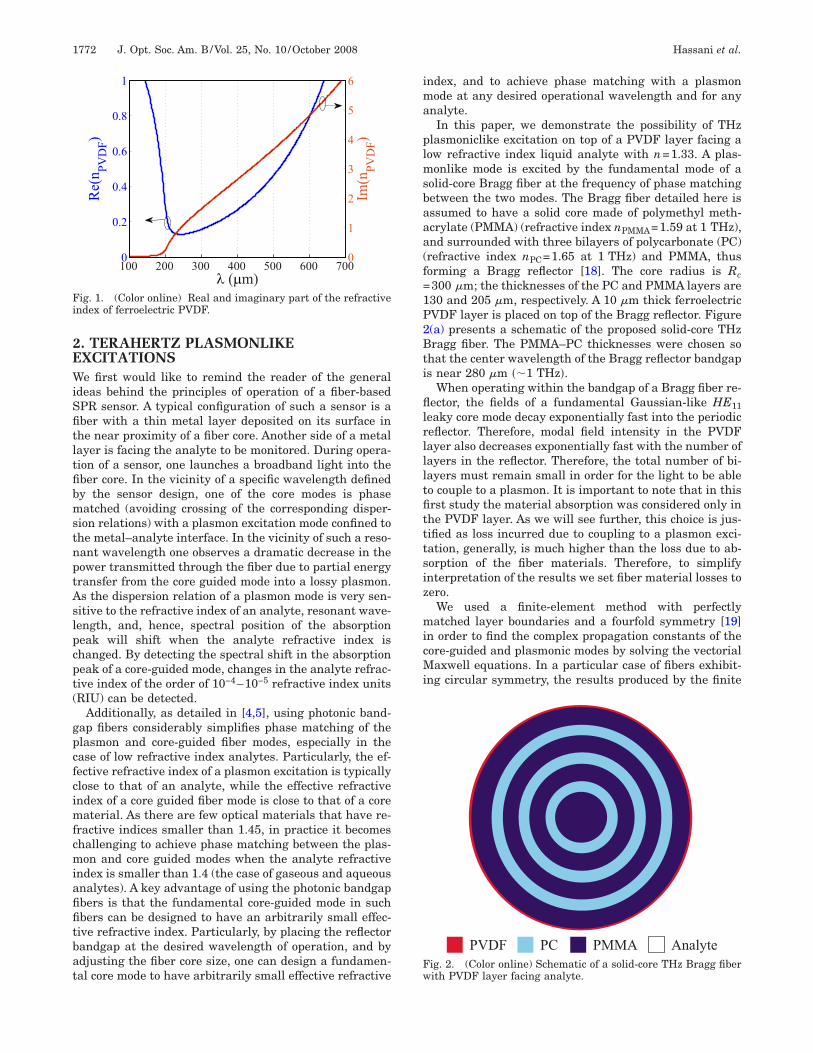
onlike mode is excited by the fundamental mode of aolid-core Bragg fiber at the frequency of phase matchingetween the two modes. The Bragg fiber detailed here isssumed to have a solid core made of polymethyl meth-crylate (PMMA) (refractive index nPMMA=1.59 at 1 THz),nd surrounded with three bilayers of polycarbonate (PC)refractive index nPC=1.65 at 1 THz) and PMMA, thusorming a Bragg reflector [18]. The core radius is Rc300 �m; the thicknesses of the PC and PMMA layers are30 and 205 �m, respectively. A 10 �m thick ferroelectricVDF layer is placed on top of the Bragg reflector. Figure(a) presents a schematic of the proposed solid-core THzragg fiber. The PMMA–PC thicknesses were chosen so
hat the center wavelength of the Bragg reflector bandgaps near 280 �m ��1 THz�.
When operating within the bandgap of a Bragg fiber re-ector, the fields of a fundamental Gaussian-like HE11
eaky core mode decay exponentially fast into the periodiceflector. Therefore, modal field intensity in the PVDFayer also decreases exponentially fast with the number ofayers in the reflector. Therefore, the total number of bi-ayers must remain small in order for the light to be ableo couple to a plasmon. It is important to note that in thisrst study the material absorption was considered only inhe PVDF layer. As we will see further, this choice is jus-ified as loss incurred due to coupling to a plasmon exci-ation, generally, is much higher than the loss due to ab-orption of the fiber materials. Therefore, to simplifynterpretation of the results we set fiber material losses toero.
We used a finite-element method with perfectlyatched layer boundaries and a fourfold symmetry [19]
n order to find the complex propagation constants of theore-guided and plasmonic modes by solving the vectorialaxwell equations. In a particular case of fibers exhibit-
ng circular symmetry, the results produced by the finite
PVDF PC PMMA Analyteig. 2. (Color online) Schematic of a solid-core THz Bragg fiberith PVDF layer facing analyte.

ettdafifcWgmnbtraa
mdrotvctipcPbibcr1l
mtCntCaAmtwpuwfiwpcomtqmtTpmt
tfgd
F�tbpma
miopisd6Fbwmpsit
FmftS=mam
Hassani et al. Vol. 25, No. 10 /October 2008 /J. Opt. Soc. Am. B 1773
lement method can be also confirmed by a transfer ma-rix method. Since we have neglected material absorption,he imaginary part of the core mode propagation constantefines modal propagation loss resulting from coupling tolossy plasmon. For a given analyte, we design a Bragg
ber reflector in such a manner as to ensure that the ef-ective refractive index of a plasmonic excitation (which islose to that of the analyte) falls within the fiber bandgap.e then vary the fiber core size to position the core-
uided mode dispersion curve in such a way as to phaseatch it with a plasmon mode. Sensing in analytes of sig-ificantly different refractive indices requires distinct fi-er designs. In all the simulations that follow we arbi-rarily assume a low refractive index analyte withefractive index of n=1.33. Nevertheless, design consider-tions presented in this paper are general and can bedapted to any analyte refractive index.Figure 3 shows the dispersion relation of the funda-ental core mode, and the plasmonic mode. The solid and
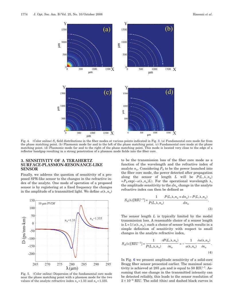
ashed black curves (blue online) present the dispersionelations of the fundamental core mode for the two valuesf the analyte refractive index of 1.33 and 1.335, respec-ively. Furthermore, Fig. 4 shows the field distributions inarious fiber modes and at several points of interest indi-ated in Fig. 3. Particularly, Fig. 4(a) shows the field dis-ribution in the fiber core mode at point A in Fig. 3, whichs located far from the point of phase matching with alasmon (point C in Fig. 3). There, the mode is well-onfined to the fiber core with only a little intensity in theVDF layer region. In Fig. 4(b) we show the field distri-ution in the plasmonic mode at point B in Fig. 3, whichs located far from the phase matching point with the fi-er core mode. As expected, most of the modal intensity isoncentrated at the PVDF–analyte interface. When theefractive index of analyte increases from na=1.33 to.335, the plasmonic mode shifts toward longer wave-engths [gray dashed curve (red online)].
ig. 3. (Color online) Dispersion relations of the core-guidedode [solid and dashed black curves (blue online)] and the sur-
ace plasmon mode [solid and dashed curves running top to bot-om (red online)] in the vicinity of the phase-matching point C.olid curves are calculated for the analyte refractive index na1.33, while dashed curves are calculated for na=1.335. Trans-ission loss of a core-guided mode (dashed-dotted curve) exhibitsstrong increase at the phase-matching point C due to efficientixing with a plasmon wave.
In Fig. 4(c) we show the field distribution in the coreode at the point C in Fig. 3, which is located exactly at
he phase matching point with a plasmon mode. At pointstrong mixing between the two modes is observed. Also
ote that the curvature of the core mode dispersion rela-ion changes in the vicinity of the phase matching point. Originally, we believed that this change is due to inter-ction of a core-guided mode with yet another fiber mode.fter performing exhaustive simulations with transferatrix and finite-element codes we are convinced that
here is no other mode located in this region. Therefore,e have to conclude that the observed anomaly in the dis-ersion relation of a core-guided mode is due to the un-sually strong and extended interaction of such a modeith a plasmonic mode. Particularly, when plotting theeld distribution in the plasmon mode at the point D,hich is located far to the right of the phase matchingoint, we still observe a very strong mixing between theore-guided and plasmonic modes. By studying positionsf bandgap edges we find that this behavior of a plas-onic mode is due to the fact that its dispersion relation
o the right of a phase matching point C approaches veryuickly the edge of a reflector bandgap. In this case,odal penetration of a plasmon mode through the reflec-
or and into the fiber core becomes strongly pronounced.his, in turn, leads to a strong interaction between thelasmon and core-guided modes even far from the phaseatching point, and as a consequence, is an anomaly in
he core mode dispersion relation.Finally, the gray dashed–dotted curve in Fig. 3 shows
he imaginary part of the effective refractive index of theundamental core mode, which also defines modal propa-ation loss due to absorption by the plasmon. In units ofecibels/centimeters such a loss is expressed as
��dB/cm� = Im�neff�40�/���cm�log 10�
= 1819�dB/cm�Im�neff��THz�. �2�
or example, at 1 THz, Im�neff��10−3 defines a1.8 dB/cm propagation loss of a fiber mode. Note that in
his paper material absorption of the fiber materials haveeen neglected with an exception of a PVDF layer. Inractice, total modal propagation loss will be approxi-ately given by the sum of the bulk loss of a core material
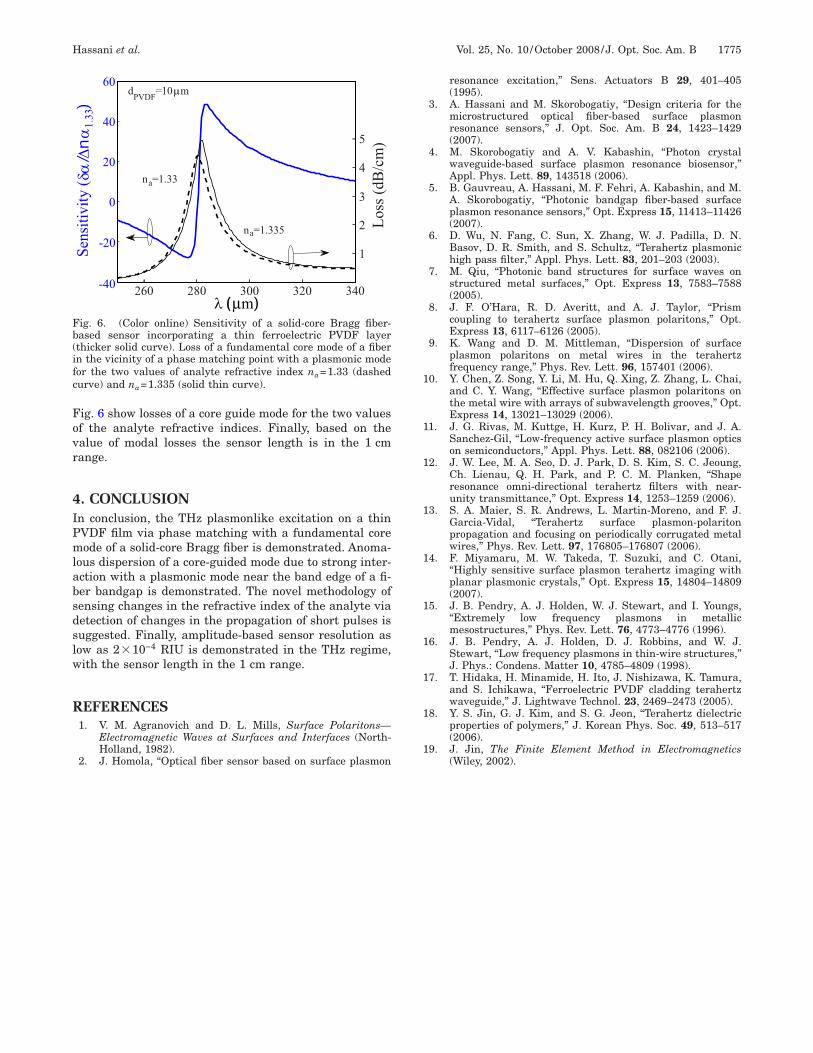
nd the loss due to coupling to a plasmon excitation.Figure 5 shows the anomalous dispersion of the funda-ental core mode of a Bragg fiber near the phase match-
ng point with a plasmon mode. Due to strong interactionf the fundamental core mode with a plasmon mode, dis-ersion of a core mode is highly sensitive to the changesn the refractive index of the analyte. For example, as-uming analyte refractive index of 1.33, the core modeispersion achieves its maximum positive value of0 ps/ �nm-km� at 282 �m [darker curve (blue online)] inig. 5). When changing the refractive index of the analytey 5�10−3 RIU, the core mode dispersion curve shifts to-ards longer wavelengths resulting in a new value ofodal dispersion of −55 ps/ �nm km� at 282 �m [higher-
eaked curve (red online)] in Fig. 5). Such a dramatic sen-itivity of modal dispersion to changes in the refractivendex of analyte can be, in principle, used for sensinghrough detection of changes in the pulse propagation.
3SSFpdsi
tfata=tr
Ttisc
IBtsb2
Ftmr mode
Fnv
1774 J. Opt. Soc. Am. B/Vol. 25, No. 10 /October 2008 Hassani et al.
. SENSITIVITY OF A TERAHERTZURFACE-PLASMON-RESONANCE-LIKEENSORinally, we address the question of sensitivity of a pro-osed SPR-like sensor to the changes in the refractive in-ex of the analyte. One mode of operation of a proposedensor is by registering at a fixed frequency the changesn the amplitude of a transmitted light. We define ��� ,na�
ig. 4. (Color online) Sz field distributions in the fiber modes athe phase matching point. (b) Plasmonic mode far and to the leftatching point. (d) Plasmonic mode far and to the right of the p
eflector bandgap resulting in a strong penetration of a plasmon
265 270 275 280 285 290 295
0
50
100
150
( m)
10 m PVDF
na=1.33na=1.335
-50
-100
-150
-200
D(ps/nm-km)
ig. 5. (Color online) Dispersion of the fundamental core modeear the phase matching point with a plasmon mode for the twoalues of the analyte refractive index n =1.33 and n =1.335.
a ao be the transmission loss of the fiber core mode as aunction of the wavelength and the refractive index ofnalyte na. Considering P0 to be the power launched intohe fiber core mode, the power detected after propagationlong the sensor of length L will be P�L ,� ,na�P0 exp�−��� ,na�L�. For the operational wavelength �,
he amplitude sensitivity to the dna change in the analyteefractive index can then be defined as
SA����RIU−1� =1
P�L,�,na�
P�L,�,na + dna� − P�L,�,na�
dna.
�3�
he sensor length L is typically limited by the modalransmission loss. A reasonable choice of a sensor lengths L=1/��� ,na�; such a choice of sensor length results in aimple definition of sensitivity with respect to smallhanges in the analyte refractive index,
SA����RIU−1� =1
P�L,�,na�
�P�L,�,na�
�na= −
1
���,na�
����,na�
�na.
�4�
n Fig. 6 we present amplitude sensitivity of a solid-coreragg fiber sensor presented earlier. The maximal sensi-
ivity is achieved at 285 �m and is equal to 50 RIU−1. As-uming that one change in the transmitted intensity cane detected reliably, this leads to the sensor resolution of�10−4 RIU. The solid (thin) and dashed black curves in
s points indicated in Fig. 3. (a) Fundamental core mode far fromphase matching point. (c) Fundamental core mode at the phaseatching point. This mode is located very close to the edge of a
fields into the fiber core.
variouof thehase m
Fovr
4IPmlabsdslw
R
1
1
1
1
1
1
1
1
1
1
Fb(ifc
Hassani et al. Vol. 25, No. 10 /October 2008 /J. Opt. Soc. Am. B 1775
ig. 6 show losses of a core guide mode for the two valuesf the analyte refractive indices. Finally, based on thealue of modal losses the sensor length is in the 1 cmange.
. CONCLUSIONn conclusion, the THz plasmonlike excitation on a thinVDF film via phase matching with a fundamental coreode of a solid-core Bragg fiber is demonstrated. Anoma-
ous dispersion of a core-guided mode due to strong inter-ction with a plasmonic mode near the band edge of a fi-er bandgap is demonstrated. The novel methodology ofensing changes in the refractive index of the analyte viaetection of changes in the propagation of short pulses isuggested. Finally, amplitude-based sensor resolution asow as 2�10−4 RIU is demonstrated in the THz regime,ith the sensor length in the 1 cm range.
EFERENCES1. V. M. Agranovich and D. L. Mills, Surface Polaritons—
Electromagnetic Waves at Surfaces and Interfaces (North-Holland, 1982).
0
20
40
60
3
Loss(dB/cm)
260 280 300 320 340
1
2
4
5
na=1.33
na=1.335
dPVDF=10 mSensitivity(
-20
-40
ig. 6. (Color online) Sensitivity of a solid-core Bragg fiber-ased sensor incorporating a thin ferroelectric PVDF layerthicker solid curve). Loss of a fundamental core mode of a fibern the vicinity of a phase matching point with a plasmonic modeor the two values of analyte refractive index na=1.33 (dashedurve) and na=1.335 (solid thin curve).
2. J. Homola, “Optical fiber sensor based on surface plasmon
resonance excitation,” Sens. Actuators B 29, 401–405(1995).
3. A. Hassani and M. Skorobogatiy, “Design criteria for themicrostructured optical fiber-based surface plasmonresonance sensors,” J. Opt. Soc. Am. B 24, 1423–1429(2007).
4. M. Skorobogatiy and A. V. Kabashin, “Photon crystalwaveguide-based surface plasmon resonance biosensor,”Appl. Phys. Lett. 89, 143518 (2006).
5. B. Gauvreau, A. Hassani, M. F. Fehri, A. Kabashin, and M.A. Skorobogatiy, “Photonic bandgap fiber-based surfaceplasmon resonance sensors,” Opt. Express 15, 11413–11426(2007).
6. D. Wu, N. Fang, C. Sun, X. Zhang, W. J. Padilla, D. N.Basov, D. R. Smith, and S. Schultz, “Terahertz plasmonichigh pass filter,” Appl. Phys. Lett. 83, 201–203 (2003).
7. M. Qiu, “Photonic band structures for surface waves onstructured metal surfaces,” Opt. Express 13, 7583–7588(2005).
8. J. F. O’Hara, R. D. Averitt, and A. J. Taylor, “Prismcoupling to terahertz surface plasmon polaritons,” Opt.Express 13, 6117–6126 (2005).
9. K. Wang and D. M. Mittleman, “Dispersion of surfaceplasmon polaritons on metal wires in the terahertzfrequency range,” Phys. Rev. Lett. 96, 157401 (2006).
0. Y. Chen, Z. Song, Y. Li, M. Hu, Q. Xing, Z. Zhang, L. Chai,and C. Y. Wang, “Effective surface plasmon polaritons onthe metal wire with arrays of subwavelength grooves,” Opt.Express 14, 13021–13029 (2006).
1. J. G. Rivas, M. Kuttge, H. Kurz, P. H. Bolivar, and J. A.Sanchez-Gil, “Low-frequency active surface plasmon opticson semiconductors,” Appl. Phys. Lett. 88, 082106 (2006).
2. J. W. Lee, M. A. Seo, D. J. Park, D. S. Kim, S. C. Jeoung,Ch. Lienau, Q. H. Park, and P. C. M. Planken, “Shaperesonance omni-directional terahertz filters with near-unity transmittance,” Opt. Express 14, 1253–1259 (2006).
3. S. A. Maier, S. R. Andrews, L. Martin-Moreno, and F. J.Garcia-Vidal, “Terahertz surface plasmon-polaritonpropagation and focusing on periodically corrugated metalwires,” Phys. Rev. Lett. 97, 176805–176807 (2006).
4. F. Miyamaru, M. W. Takeda, T. Suzuki, and C. Otani,“Highly sensitive surface plasmon terahertz imaging withplanar plasmonic crystals,” Opt. Express 15, 14804–14809(2007).
5. J. B. Pendry, A. J. Holden, W. J. Stewart, and I. Youngs,“Extremely low frequency plasmons in metallicmesostructures,” Phys. Rev. Lett. 76, 4773–4776 (1996).
6. J. B. Pendry, A. J. Holden, D. J. Robbins, and W. J.Stewart, “Low frequency plasmons in thin-wire structures,”J. Phys.: Condens. Matter 10, 4785–4809 (1998).
7. T. Hidaka, H. Minamide, H. Ito, J. Nishizawa, K. Tamura,and S. Ichikawa, “Ferroelectric PVDF cladding terahertzwaveguide,” J. Lightwave Technol. 23, 2469–2473 (2005).
8. Y. S. Jin, G. J. Kim, and S. G. Jeon, “Terahertz dielectricproperties of polymers,” J. Korean Phys. Soc. 49, 513–517(2006).
9. J. Jin, The Finite Element Method in Electromagnetics
(Wiley, 2002).


![Terahertz electromagnetic crystal waveguide fabricated by ...gehm/pubs/OptExp.19.3962.pdfapplications and the micro/nano-fabrication methods in use at optical frequencies [24, 25].](https://static.fdocuments.in/doc/165x107/5f95fdd70b47bf7fee521dd6/terahertz-electromagnetic-crystal-waveguide-fabricated-by-gehmpubsoptexp193962pdf.jpg)

![Review Article A Review of Computational Electromagnetic ...et al. [ ] used metamaterial made up of periodic graphene microribbon arrays for terahertz plasmon excitations and demonstrated](https://static.fdocuments.in/doc/165x107/60bf77d5262f570c1e13764b/review-article-a-review-of-computational-electromagnetic-et-al-used-metamaterial.jpg)