Surface Modification of Tokamak Fixed Limiter Used in High-Field Tokamak TRIAM-1
11
This article was downloaded by: [Texas A & M International University] On: 05 October 2014, At: 09:45 Publisher: Taylor & Francis Informa Ltd Registered in England and Wales Registered Number: 1072954 Registered office: Mortimer House, 37-41 Mortimer Street, London W1T 3JH, UK Journal of Nuclear Science and Technology Publication details, including instructions for authors and subscription information: http://www.tandfonline.com/loi/tnst20 Surface Modification of Tokamak Fixed Limiter Used in High-Field Tokamak TRIAM-1 Kazutoshi TOKUNAGA a , Tadashi FUJIWARA a , Yoshio MIYAMOTO b , Takeo MUROGA b , Naoaki YOSHIDA b , Satoshi ITOH b & Group TRIAM b a Interdisciplinary Graduate School of Engineering Sciences, Kyushu University b Research Institute for Applied Mechanics, Kyushu University , Kasuga-koen, Kasuga-shi , 816 Published online: 15 Mar 2012. To cite this article: Kazutoshi TOKUNAGA , Tadashi FUJIWARA , Yoshio MIYAMOTO , Takeo MUROGA , Naoaki YOSHIDA , Satoshi ITOH & Group TRIAM (1990) Surface Modification of Tokamak Fixed Limiter Used in High-Field Tokamak TRIAM-1, Journal of Nuclear Science and Technology, 27:4, 333-342, DOI: 10.1080/18811248.1990.9731191 To link to this article: http://dx.doi.org/10.1080/18811248.1990.9731191 PLEASE SCROLL DOWN FOR ARTICLE Taylor & Francis makes every effort to ensure the accuracy of all the information (the “Content”) contained in the publications on our platform. However, Taylor & Francis, our agents, and our licensors make no representations or warranties whatsoever as to the accuracy, completeness, or suitability for any purpose of the Content. Any opinions and views expressed in this publication are the opinions and views of the authors, and are not the views of or endorsed by Taylor & Francis. The accuracy of the Content should not be relied upon and should be independently verified with primary sources of information. Taylor and Francis shall not be liable for any losses, actions, claims, proceedings, demands, costs, expenses, damages, and other liabilities whatsoever or howsoever caused arising directly or indirectly in connection with, in relation to or arising out of the use of the Content. This article may be used for research, teaching, and private study purposes. Any substantial or systematic reproduction, redistribution, reselling, loan, sub-licensing, systematic supply, or distribution in any form to anyone is expressly forbidden. Terms & Conditions of access and use can be found at http://www.tandfonline.com/page/terms-and- conditions
Transcript of Surface Modification of Tokamak Fixed Limiter Used in High-Field Tokamak TRIAM-1

This article was downloaded by: [Texas A & M International University]On: 05 October 2014, At: 09:45Publisher: Taylor & FrancisInforma Ltd Registered in England and Wales Registered Number: 1072954 Registeredoffice: Mortimer House, 37-41 Mortimer Street, London W1T 3JH, UK
Journal of Nuclear Science andTechnologyPublication details, including instructions for authors andsubscription information:http://www.tandfonline.com/loi/tnst20
Surface Modification of Tokamak FixedLimiter Used in High-Field TokamakTRIAM-1Kazutoshi TOKUNAGA a , Tadashi FUJIWARA a , Yoshio MIYAMOTO b ,Takeo MUROGA b , Naoaki YOSHIDA b , Satoshi ITOH b & Group TRIAMb
a Interdisciplinary Graduate School of Engineering Sciences, KyushuUniversityb Research Institute for Applied Mechanics, Kyushu University ,Kasuga-koen, Kasuga-shi , 816Published online: 15 Mar 2012.
To cite this article: Kazutoshi TOKUNAGA , Tadashi FUJIWARA , Yoshio MIYAMOTO , Takeo MUROGA ,Naoaki YOSHIDA , Satoshi ITOH & Group TRIAM (1990) Surface Modification of Tokamak Fixed LimiterUsed in High-Field Tokamak TRIAM-1, Journal of Nuclear Science and Technology, 27:4, 333-342, DOI:10.1080/18811248.1990.9731191
To link to this article: http://dx.doi.org/10.1080/18811248.1990.9731191
PLEASE SCROLL DOWN FOR ARTICLE
Taylor & Francis makes every effort to ensure the accuracy of all the information (the“Content”) contained in the publications on our platform. However, Taylor & Francis, ouragents, and our licensors make no representations or warranties whatsoever as to theaccuracy, completeness, or suitability for any purpose of the Content. Any opinions andviews expressed in this publication are the opinions and views of the authors, and arenot the views of or endorsed by Taylor & Francis. The accuracy of the Content should notbe relied upon and should be independently verified with primary sources of information.Taylor and Francis shall not be liable for any losses, actions, claims, proceedings, demands,costs, expenses, damages, and other liabilities whatsoever or howsoever caused arisingdirectly or indirectly in connection with, in relation to or arising out of the use of theContent.
This article may be used for research, teaching, and private study purposes. Anysubstantial or systematic reproduction, redistribution, reselling, loan, sub-licensing,systematic supply, or distribution in any form to anyone is expressly forbidden. Terms &Conditions of access and use can be found at http://www.tandfonline.com/page/terms-and-conditions
Journal of NucLEAR SciENCE and TECHNOLOGY, 27[4], pp. 333-342 (April 1990).
Surface Modification of Tokamak Fixed Limiter Used in High-Field Tokamak TRIAM-1
Kazutoshi TOKUNAGA,
Interdisciplinary Graduate School of Engineering Sciences, Kyushu University*
Tadashi FUJIWARA, Yoshio MIYAMOTO, Takeo MUROGA, Naoaki YOSHIDA, Satoshi ITOH and TRIAM Group
Research Institute jor Applied Mechanics, Kyushu University*
Received july 28, 1989
The surface morphology and composition changes of a Mo fixed limiter used in the HighField Tokamak TRIAM-1 after about 70,000 hydrogen plasma discharges have been investigated by means of optical microscope, SEM-EDS and AES. Significant difference in surface damage is observed between the electron drift side and the ion drift side.
The damage on the electron drift side is characterized by melting, cracking, cone-like protuberance, droplet, eutectic and impurity accumulation. This is considered to be caused by the overlapped effects of the heat load from the plasma, which decreases with increasing distance from the plasma center, and the impurity accumulation which originated from the stainless steel vacl.\um vessel and the limiter itself.
The kinds of damage on the ion drift side are melting due to arcing, sputtering, blistering and color change of the surface due to impurity accumulation. The distribution of these damages changes with the distance from the limiter edge. The damage observed on the ion drift side is considered to be caused by the synergistic effects of sputtering due to ion bombardment, impurity accumulation and heat load due to arcing.
KEYWORDS: plasma-wall interactions, TRIAM-1 tokamak, modifications, limiters, molybdenum, heat load, impurity accumulation, hydrogen bombardment, melting, arcing, sputtering, blistering, plasma
333
I. INTRODUCTION
The damage of first walls and impurity flux into the plasma due to the plasma wall interactions are viewed as major problems in developing fusion reactors such as a tokamak'1J. New materials which are capable of withstanding plasma loading and reducing impurity emission must be developed.
tering, blistering, arcing, melting and impurity accumulation c2J-c4 J. However, the synergism of these effects, which should have significant positional dependence in the torus, have not been well clarified.
Direct observations of surface modification of first walls in a tokamak can provide valuable information for the design of new first wall materials. Studies with this aim have been carried out in many tokamak devices. They have shown prominent effects of sput-
In this study, a Mo limiter used in the High-Field Tokamak TRIAM-lcsJ-Cn has been investigated with respect to both surface morphological and compositional changes after long term operation. Observations of both sides of a circular limiter have made it possible to examine modifications of both electron and ion sides at various poloidal directions. The contribution of the surface loading such * Kasuga-koen, Kasuga.shi 816.
-39-
Dow
nloa
ded
by [
Tex
as A
& M
Int
erna
tiona
l Uni
vers
ity]
at 0
9:45
05
Oct
ober
201
4

334
as heat and particle flux, and impurity accumulation is discussed based on the data obtained for the radial and circumferential distribution of the modifications.
ll. EXPERIMENTAL METHODS
The device parameters of the TRIAM-1 are summarized in Table 1<s)-(7). Ohmic and turbulent heating discharge experiments by hydrogen plasma were performed using a Mo limiter fixed to the 304 stainless steel vacuum chamber as shown in Fig. 1. This limiter is ·composed of two half-rings with an inner diameter of 80 mm, a width of 13 mm and a thickness of 5 mm<•l-(7).
Table 1 Main parameters of TRIAM-1 tokamak and plasma parameters
Major radius Plasma radius Toroidal magnetic field
25.4 em 4.0cm 2.4-3.6 T
Plasma current 15-47 kA Line average electron density 1.5-2.2 x 1013 cm- 3
Electron temperature 200-640 e V Ion temperature Duration time
80-580eV <20ms
]. Nucl. Sci. Techno!.,
After about 70,000 discharges in 7 years, this limiter was extracted and examined with an optical microscope, SEM-EDS and AES.
m. RESULTS AND DISCUSSION
1. Distribution of Surface Modification Figure 1 is the schematic representation
of the distribution of surface modification on the electron drift side and the ion drift side of the limiter. Following significant differences in surface modification were observed between these two sides. On the electron drift side, melting (areas A and B in Fig. 1),
cracking (area A), cone-like protuberance (area A), eutectic (area B), droplet (area B and C) and multilayer of impurity accumulation (area C)
were observed. On the ion drift side, on the other hand, the major modifications were melting due to arcing (area D), sputtering (area D), blistering (area E), impurity accumulation (area F) and droplets (area F). But, the distribution of the modifications on both sides made circular stripe patterns depending on the radial distance from the limiter inner edge. The heavy damaged regions were located at the inside and outside of the torus. Particu-
outside inside inside outside
electron drift side ion drift side
On the electron drift side, A: Melting and cracking, B: Droplets and impurity accumulation layer overall remelted, C : Droplets and partially remelted or non-melted impurity accumulation layer.
On the ion drift side, D: Arcing and Sputtering, E: Blistering, F: Impurity accumulation.
Fig. 1 Areal distribution of surface modifications on electron drift side and ion drift side of Mo limiter
-40-
Dow
nloa
ded
by [
Tex
as A
& M
Int
erna
tiona
l Uni
vers
ity]
at 0
9:45
05
Oct
ober
201
4

Vol. 27, No. 4 (Apr. 1990)
larly, modification of the inner part of the torus was quite prominent. This distribution is expected to reflect the directional dependence of the plasma instability< B). Details of damage on the electron drift side and the ion drift side will be described in Sees. 11-2, 3, respectively.
2. Electron Drift Side ( 1 ) Surface Morphology In the vicinity of the inner edge of the
limiter (area A in Fig. 1), the surface layer was molten and many cracks were produced by thermal stress due to thermal loading. Melting is expected to be enhanced by the reduced thermal conductivity due to crack formation. Micrographs in Photo. 1 shows the edge of the inner part of the torus where the highest heat loading is expected. Here, a number of cone-like protuberances and deep cracks in the form of cross stripes are ob-
335
served. In this area, weight loss was observed and impurity was ejected. The modification of this type is weaken with increasing distance from the inner edge of the limiter. In the area B, locating outside the area A, the surface is covered with droplets and impurities forming eutectic or multilayer (see Photo. 3(2)-(4)). The droplets size and areal droplet volume decrease with increasing the distance from the inner edge irrespective of the poloidal direction. Thus, it is expected that droplets were originally sprayed out from the molten surface (area A) in the vicinity of the inner edge of the limiter as shown in Photo. 1. It is considered that these droplets arose from the force caused by boiling or magnetic field< 9J<t•J. This implies that the droplet generation as well as evaporation can be an important source of thermal release of metal on the electron drift side of the limiter.
Photo. 1 SEM image on electron drift side (a) and optical microscope image on plasma side (b) of limiter edge in inner part of torus
( 2 ) Cross-sectional View of Modifications Photograph 2 shows a cross-sectional view
in the vicinity of the area shown in Photo. 1. The recrystallized surface layer with a thick-
ness of about 0.1 mm are followed by the layer of fine structures of about 0.1 mm thickness. Below these layers, there are laminar structures representing the original manufac-
-41-
Dow
nloa
ded
by [
Tex
as A
& M
Int
erna
tiona
l Uni
vers
ity]
at 0
9:45
05
Oct
ober
201
4

336 ]. Nucl. Sci. Techno!.,
ture. It is considered that the top layer of the original structures was canceled by melting and solidification and ripened by succeeding
heat load. The intermediate layer is considered to be heat-affected and changes gradually to the original manufacture.
(1}
Photo. 2 Optical microscope image of cross section in vicinity of area shown in Photo. 1
(2) (3) Photo. 3 SEM image (a) and compositional image (b) of electron
drift side in order from inner to outer positions
-42-
(4)
Dow
nloa
ded
by [
Tex
as A
& M
Int
erna
tiona
l Uni
vers
ity]
at 0
9:45
05
Oct
ober
201
4
Vol. 27, No. 4 (Apr. 1990)
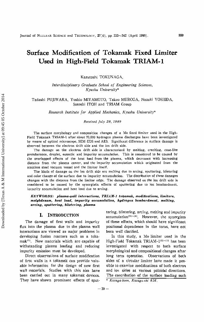
( 3 ) Impurity Accumulation Photograph 3(1)"-'(4) shows (a) SEM (sec
ondary electron) and (b) composition (modified backscattered electron) images of representative positions of limiter in order from the inner to the outer parts.
SEM and composition images show that in the vicinity of the inner edge (Photo. 3(1) and area A in Fig. 1), the surface layer is molten and the surface compositions are almost uniform. Figure 2(1) shows spectrum of EDS analyses in this area. It shows no signal of metallic impurities exceeding the limit of detection except bulk Mo.
( 1 ) Mo
Mo
(2) Fe
(1) and (2) correspond with Photo. 3(1) and (2).
Fig. 2 Spectrum of EDS analyses
At the outer part (Photo. 3(2) and area B in Fig. 1), a molten surface with uniform composition is also observed. However, EDS analyses (Fig. 2(2)) show the existence of Fe, Cr and Ni in addition to Mo. A number of hemispheric projections and cracks are observed on the surface. These hemispheric projections are considered to be formed by arrival of droplets that originated from the inner molten area and by fusing those droplets with surface materials due to the temperature rise induced by plasma loading.
337
In the outside of this area (Pnoto. 3(3) and area C in Fig. 1), the surface layer is partially molten and compositional distribution is not uniform. The existence of Mo, Fe, Cr and Ni were shown by EDS analyses. Spherical droplets are also observed. This shows that after arrival of these droplets, the surface temperature was not so high enough that the droplets fused with surface materials.
At the outermost part (Photo. 3(4) and area c in Fig. 1), no evidence of surface melting but covering with redeposited layers, which are partially exfoliated and composed of Fe, Cr, Ni and Mo, is observed. Stereoscopic observation indicate that the thickness of this layer is about 2 11m with small areal thickness variations.
Photograph 4(1) and (2) show SEM micrograph of cross section and line profile analyses of Mo, Fe, Cr and Ni along the reference line in the area corresponding to Photo. 3(2) and (3), respectively. As shown in Photo. 4(1), it is clear that the deposited layer and Mo base were molten together and the thickness of molten and resolidified zone is about 7 f1m. The composition of these layer is rich in Mo and Fe. Impurity Cr has a tendency to segregate near the surface.
As shown in Photo. 4(2), the deposited layer with a thickness of about 311m exists on the Mo base. Judging from the clear change of Fe concentration at the interface, the deposited layer and Mo base were not mixed by heat load. The deposited layer is composed of Mo, Fe, Cr and Ni. The result of cross-sectional observation are consist with the surface observation.
In the area B in Fig. 1 (Photo. 3(2)), the surface impurity layers fuse with the base surface resulting in strong adhesion. However, in the area C in Fig. 1 (Photo. 3(4)), the impurity accumulation layer is not molten and, thus, loosely attached with the base surface. As a result, the surface impurity layer is partially exfoliated. The difference in the surface structure of these two areas is considered to be caused by the heat load with positional variation after impurity arrival.
-43-
Dow
nloa
ded
by [
Tex
as A
& M
Int
erna
tiona
l Uni
vers
ity]
at 0
9:45
05
Oct
ober
201
4

338 ]. Nucl. Sci. Techno!.,
(1) MoLa, FeKa, CrKa, NiKa (To Photo. 3(2)) (2) MoLa, FeKa, CrKa, NiKa (To Photo. 3(4))
Photo. 4 (1), (2) SEM image and line profile analyses along reference line The range of MoLa is 10 times larger than that of FeKa,CrKa and NiKa.
( 4 ) Measurements of Depth Distribution of Impurities Using AES
Figure 3 shows Auger spectrum of the impurity deposit area (area C in Fig. 1) after
etching for 350 s by 5 keV Ar ions. It can be seen that the surface is composed of 0 and C in addition to metallic impurities, and C : peak is that of carbide type.
-44-
Dow
nloa
ded
by [
Tex
as A
& M
Int
erna
tiona
l Uni
vers
ity]
at 0
9:45
05
Oct
ober
201
4

Vol. 27, No. 4 (Apr. 1990)
900
850
BOO rn ~ 750 ::s 0 700 (.)
650
600
339
100 200 300 400 500 600 700 BOO 900 1000
Kinetic Energy I eV Fig. 3 Auger spectrum of impurity deposit area (area C
in Fig. 1) after etching for 5 keY Ar ions
a 80
r! 0 40
20
Figure 4(a)"-'(C) shows AES sputter depth profiles at the positions corresponding to Photo. 3(1), (2) and (4), respectively. Figure 4(a) indicates that, at the molten area shown in Photo. 4(1), no metallic impurities but 0 and C are accumulated near the surface. However, metallic impurities of Fe, Cr and Mo are accumulated in the area shown m Photo. 3(2) and (4) as indicated in Fig. 4(b) and (c). Since the limiter was exposed to air prior to analysis, impurity 0 near surface is expected to include some environmental effects such as exposure to the air. A comparison of Fig. 4(b) with (c) shows that the Cr concentration is locally high at the surface of the molten impurity layer probably due to segregation during melting and succeeding solidification. Impurity C exists in the part of the interior surface of the limiter and the formation of carbide is observed in Fig. 3. This is because that carbon deposited on the limiter as well as other impurities and formed carbide by reaction on deposited materials. The above results for the depth compositional distribution using AES reasonably support the speculation of the metallic impurity history shown in Sec. ill-2( 3 ).
00~~~~~;=~~~~~ 4.0 so 60 7.0 80 9.0 10.0
The area of a, b, c correspond to Photo. 3(1), (2) and (4), respectively.
Fig. 4(a)- (c) Auger sputter depth profile/
80
60
r! ;; 40
20
80
60
r! 0 40
-45-
Sputter Time (min)
Mo
1.2 24 3.6 48 60 7.2 8.4 96 10.8 120 Sputter Time (min)
Mo
eo eo 100 12.0 14.0 160 reo 200 Sputter Time (min)
Dow
nloa
ded
by [
Tex
as A
& M
Int
erna
tiona
l Uni
vers
ity]
at 0
9:45
05
Oct
ober
201
4

:!40
( 5) Factors Controlling Modifications of Electron Drift Side
Thermal effects due to plasma loading, i. e. melting, cracking, evaporation and emission of droplet, are most significant on the inner side of the limiter. The absence of impurities at this area is expected to be due to the evaporation or spraying out of droplets by repeating heat load. Thermal loading decreased with increasing distance from the inner edge of the limiter, and impurities deposited on such area formed eutectic or layer.
The factors controlling the modifications on the electron drift side are summarized as thermal loading and impurity deposition. Synergistic effects of these two factors result in complicated and position dependent modifications observed on the electron drift side.
3. Ion Drift Side Modifications on the ion drift side were
remarkably different from those of the electron drift side. Arcing, sputtering, blistering and impurity accumulation were observed.
( 1 ) Arcing and Sputtering Photograph 5(a) shows a SEM image of
the area D in Fig. 1. The surface is molten resulting i11 a fine uneven morphology. This modification is considered to be formed by repeated linear arcs. In the area near the boundary, arcings do not occur often and typical linear melting due to arcing are observed (Photo. 5(b)). The direction of the arc spot motion was random because the magnetic field was normal to the surface on the ion drift side. Generally, in small tokamaks such as the TRIAM-1, heavy arc damage is not expected because the discharge duration time is shortc11l. However, in the present case, arcing occurred as major damage on the ion drift side. The reason of this discrepancy remains to be clarified by taking into account the contribution of the plasma characters.
In addition, surface is modified into a wavy structure as shown in Photo. 5(b). This is considered to be the result of erosion due to sputtering_ caused by ion bombardment. Stereoscopic observations indicate that the erosion depth is about 1'""'"'5 p.m. Assuming that hydrogen ions with an energy of about 100 eV,
]. Nucl. Sci. Technol.,
Photo. 5 SEM image of areas affected by (a) heavy and (b) slight arcing on ion drift side (area D in Fig. 1)
which is the typical energy of plasma in the TRIAM-1, solely contributed to erosion by sputtering, the hydrogen loading on the limiter surface is roughly estimated to be 1018 particles/cm2/discharge. It has been reported that sputtering induced by 0 can be the dominant erosion mechanism at the limiter02l.
In the TRIAM-1, the densities of 0 and C in the plasma were estimated to be less than 1/100 of that of H. But the sputtering yield of 0 and C ions may be multi-charged with higher energies and, thus, with higher sputtering yield. Therefore, the sputtering by 0 and C as well as H may be one of the major reasons of the present prominent erosion.
EDS analyses showed no metallic impurity in this area. This can be interpreted as high sputtering-induced erosion rate induced by sputtering exceeding the impurity deposition rate.
( 2 ) Blistering Circular images with various sizes from 10
to 200 p.m are observed by optical microscope
-46-
Dow
nloa
ded
by [
Tex
as A
& M
Int
erna
tiona
l Uni
vers
ity]
at 0
9:45
05
Oct
ober
201
4

Vol. 27, No. 4 (Apr. 1990)
in the area E of Fig. 1 as shown in Photo. 6. They are believed to be blisters, because surface scratches similar to those observed in non damaged surface, which are expected to be introduced during fabrication, indicate that the circular images do not represent any foreign materials but evolution of the surface morphology.
Photo. 6 Optical microscope image of blistering zone on ion drift side (area E in Fig. 1)
Ion bombardment experiments have shown that the diameter of a blister is about tenth that of ion rangeC''l. Based on this relation, the diameter of blister on the Mo limiter in the TRIAM-1 is expected to be less than 10 nm, which is 3 to 4 order smaller than those actually observed. This difference is expected to be due to the laminar structure produced during fabrication. Formation of the present large blisters is considered to be caused by agglomerating implanted H ions to the plane defects of the laminar structure.
( 3) Impurity Accumulation Photograph 7 shows (a) SEM micrograph
and (b) compositional images in the outermost
341
area on the ion drift side (area F in Fig. 1). The observation using SEM and the chemical analyses with EDS indicates that the impurity layer, which is composed of Fe, Cr, Ni and Mo, deposits on the base limiter surface. The adhesion strength of the impurity layer is expected to be low because the impurity layer is partially exfoliated. The wavy modifications due to sputtering and arcing also occur on the impurity layer.
Photo. 7 SEM image (a) and compositional image (b) of impurity deposit area on ion drift side
( 4 ) Factors Determining Modifications of Ion Drift Side
The major factors determining the modifications of the ion drift side are arcing, ion bombardment and impurity accumulation. The modification observed presently are reasonably interpreted as the results of synergistic effects of these factors whose contribution have prominent positional dependence.
-47-
Dow
nloa
ded
by [
Tex
as A
& M
Int
erna
tiona
l Uni
vers
ity]
at 0
9:45
05
Oct
ober
201
4

342
IV. CONCLUSION
Examinations of a Mo limiter after long term operation in the High-Field Tokamak TRIAM-1 indicate that the limiter surface were drastically modified in a complex manner and that the significant differences in the modification on the electron side and the ion side occurred.
On the electron drift side, the multiformity of the damage distribution is expected to be attributed to the synergism of the heat load from plasma and impurity accumulation due to plasma wall interactions. On the other hand, the damages observed on the ion drift side indicate that they were caused by synergistic effects of sputtering due to ion bombardment, impurity accumulation and heat loading due to arcing. On both limiter sides, the locality of the contribution of these factors are expected to result in the present complex and position-dependent surface modifications.
ACKNOWLEDGMENT
The authors gratefully acknowledge the assistance of UL V AC-PHI. Inc. and VG Scientific Ltd. in performing AES analyses.
f. Nucl. Sci. Techno/.,
-REFERENCEs-
(1) McCRACKEN, G. M., SToTT, P. E.: Plasma-surface interactions in tokamaks, Nucl. Fusion, 19[7]. 889 (1979).
(2) HILDEBRANDT, D., HINTZE, W., ]UETTNER, B., LAUX, M., LINGERTAT, ]., PECH, P., REINER, H.D., STRUSNY, H., WoLFF, H.: f. Nucl. Mater., 93/94, 310 (1980).
(3) FERRO, C., FRANCONI, E., NERI, A.: ibid., 111 I 112, 573 (1982).
(4) WoLFF, H., GROTE, H., HERRMANN, A., HILDEBRANDT, D., LAUX, M., PECH, P., REINER, H. D., ZIEGENHAGEN, G.: ibid., 145/147, 671 (1987).
(5) HIRAKI, N., IToH, S., KAWAI, Y., Tm, K., NAKAMURA, K., MITARAI, 0.: Rep. Res. Inst. Appl. Mech., XXVii[85J, 85 (1979).
(6) Tor, K., HIRAKI, N., NAKAMURA, K., MITARAI, 0., KAWAI, Y., ITOH, S.: Nucl. Fusion, 20[9], 1169 (1980).
(7) lToH, S., NAKAMURA, Y., HIRAKI, N., NAKAMURA, K., KIKUCHI, M., NAGAO, A., WATANABE, T.: 11th European Conf. Controlled Fusion and Plasma Physics, (Part 1), 405 (1983), European Phys. Soc.
(8) FRANCIS, F. Chen: "Introduction to Plasma Physics", (1974), Plenum Press, New York.
(9) GLOCK, E. and PULSATOR Team: ]. Nucl. Mater., 93/94, 305 (1980).
M WoLFER, W. G., HAssANEIN, A.M.: ibid., 111 /112, 560 (1982).
~l) MuRRAY,]. G.: Fusion Techno!., 8, 664 (1985). M RoBERTO, ]. B., ZuHR, R. A., WITHROW, S. P.:
f. Nucl. Mater., 93/94,146 (1980). M KAMINSKY, M.: "Radiation Effects on Solid
Surface", 112 (1976), Am. Chern. Soc.
-48-
Dow
nloa
ded
by [
Tex
as A
& M
Int
erna
tiona
l Uni
vers
ity]
at 0
9:45
05
Oct
ober
201
4