Support RAND For More Information TO MITIGATE JAMMING AND INCREASE LPI/LPD..... 21 The CDL Family...
55
This PDF document was made available from www.rand.org as a public service of the RAND Corporation. 6 Jump down to document Visit RAND at www.rand.org Explore RAND Project AIR FORCE View document details This document and trademark(s) contained herein are protected by law as indicated in a notice appearing later in this work. This electronic representation of RAND intellectual property is provided for non-commercial use only. Permission is required from RAND to reproduce, or reuse in another form, any of our research documents for commercial use. Limited Electronic Distribution Rights For More Information CHILD POLICY CIVIL JUSTICE EDUCATION ENERGY AND ENVIRONMENT HEALTH AND HEALTH CARE INTERNATIONAL AFFAIRS NATIONAL SECURITY POPULATION AND AGING PUBLIC SAFETY SCIENCE AND TECHNOLOGY SUBSTANCE ABUSE TERRORISM AND HOMELAND SECURITY TRANSPORTATION AND INFRASTRUCTURE The RAND Corporation is a nonprofit research organization providing objective analysis and effective solutions that address the challenges facing the public and private sectors around the world. Purchase this document Browse Books & Publications Make a charitable contribution Support RAND
Transcript of Support RAND For More Information TO MITIGATE JAMMING AND INCREASE LPI/LPD..... 21 The CDL Family...

This PDF document was made available from www.rand.org as a public
service of the RAND Corporation.
6Jump down to document
Visit RAND at www.rand.org
Explore RAND Project AIR FORCE
View document details
This document and trademark(s) contained herein are protected by law as indicated in a notice appearing later in this work. This electronic representation of RAND intellectual property is provided for non-commercial use only. Permission is required from RAND to reproduce, or reuse in another form, any of our research documents for commercial use.
Limited Electronic Distribution Rights
For More Information
CHILD POLICY
CIVIL JUSTICE
EDUCATION
ENERGY AND ENVIRONMENT
HEALTH AND HEALTH CARE
INTERNATIONAL AFFAIRS
NATIONAL SECURITY
POPULATION AND AGING
PUBLIC SAFETY
SCIENCE AND TECHNOLOGY
SUBSTANCE ABUSE
TERRORISM AND HOMELAND SECURITY
TRANSPORTATION ANDINFRASTRUCTURE
The RAND Corporation is a nonprofit research organization providing objective analysis and effective solutions that address the challenges facing the public and private sectors around the world.
Purchase this document
Browse Books & Publications
Make a charitable contribution
Support RAND

This product is part of the RAND Corporation technical report series. Reports may
include research findings on a specific topic that is limited in scope; present discus-
sions of the methodology employed in research; provide literature reviews, survey
instruments, modeling exercises, guidelines for practitioners and research profes-
sionals, and supporting documentation; or deliver preliminary findings. All RAND
reports undergo rigorous peer review to ensure that they meet high standards for re-
search quality and objectivity.

Communications Networks to Support Integrated Intelligence, Surveillance, Reconnaissance, and Strike Operations
Elham Ghashghai
Prepared for the United States Air Force
Approved for public release; distribution unlimited

The RAND Corporation is a nonprofit research organization providing objective analysis and effective solutions that address the challenges facing the public and private sectors around the world. RAND’s publications do not necessarily reflect the opinions of its research clients and sponsors.
R® is a registered trademark.
© Copyright 2004 RAND Corporation
All rights reserved. No part of this book may be reproduced in any form by any electronic or mechanical means (including photocopying, recording, or information storage and retrieval) without permission in writing from RAND.
Published 2004 by the RAND Corporation1776 Main Street, P.O. Box 2138, Santa Monica, CA 90407-2138
1200 South Hayes Street, Arlington, VA 22202-5050201 North Craig Street, Suite 202, Pittsburgh, PA 15213-1516
RAND URL: http://www.rand.org/To order RAND documents or to obtain additional information, contact
Distribution Services: Telephone: (310) 451-7002; Fax: (310) 451-6915; Email: [email protected]
Library of Congress Cataloging-in-Publication Data
Ghashghai, Elham. Communications networks to support integrated intelligence, surveillance, reconnaissance, and strike operations / Elham Ghashghai. p. cm. “TR-159.” Includes bibliographical references. ISBN 0-8330-3664-5 (pbk.) 1. Command and control systems—United States. 2. United States—Armed Forces—Communication systems. I. Title.
UB212.G49 2004 355.3'3041'0973—dc22
2004018245
The research reported here was sponsored by the United States Air Force under Contract F49642-01-C-0003. Further information may be obtained from the Strategic Planning Division, Directorate of Plans, Hq USAF.

iii
Preface
U.S. military operations in the 21st century rely heavily on receiving anddistributing information to and from the field of operation. Immense amounts ofdata must be collected, processed, and fused into knowledge via high-capacitynetworks. This report addresses the communications challenges associated withintegrating current and future intelligence, surveillance, and reconnaissance(ISR) assets effectively with weapons platforms and the weapons themselves. Itevaluates a variety of options for satisfying the needs of robust communicationssystems.
The research was sponsored by Major General Ronald F. Sams (Director,Intelligence, Surveillance, and Reconnaissance), Brigadier General Daniel Leaf(Director, Operational Requirements), and Mr. Harry Disbrow, all of whomreport to the Deputy Chief of Staff of the Air Force, Air and Space Operations.The action officer was LtCol Karen Clark. This research was conducted withinthe Aerospace Force Development Program of RAND Project AIR FORCE as partof the “Integrated ISR-Strike” study led by Dr. Glenn Buchan. For furtherinformation, contact the author, Elham Ghashghai (310-393-0411, x7211;[email protected]).
RAND Project AIR FORCE
RAND Project AIR FORCE (PAF), a division of the RAND Corporation, is theU.S. Air Force’s federally funded research and development center for studiesand analyses. PAF provides the Air Force with independent analyses of policyalternatives affecting the development, employment, combat readiness, andsupport of current and future aerospace forces. Research is performed in fourprograms: Aerospace Force Development; Manpower, Personnel, and Training;Resource Management; and Strategy and Doctrine.
Additional information about PAF is available on our web site athttp://www.rand.org/paf.


v
Contents
Preface ................................................... iii
Figures ................................................... vii
Tables ................................................... ix
Summary ................................................. xi
Acknowledgments........................................... xv
Acronyms .................................................xvii
1. INTRODUCTION ....................................... 1Organization of This Report ................................ 3
2. METHODOLOGY ....................................... 5Assumptions and Limitations ............................... 5Threats, Requirements, and Baselines ......................... 5Systems and Programs .................................... 6
Joint Tactical Information Distribution System (JTIDS)............ 6Joint Tactical Radio System (JTRS) .......................... 6The Common Data Link (CDL) Family ....................... 7
Data-Rate Requirement.................................... 8
3. ANALYSIS OF THREATS FROM JAMMING AND SIGINTRECEIVERS............................................ 11Jamming Analysis ....................................... 11Signal Detection Analysis .................................. 15
4. OPTIONS TO MITIGATE JAMMING AND INCREASE LPI/LPD..... 21The CDL Family Provides an Adequate Capacity and
Some Protection Against Detection and Jamming,But It May Not Be Enough .............................. 21
Spreading the Signal Over Time and Bandwidth IncreasesLPI/LPD But Degrades Link Capacity...................... 22
Smart Antennae Increase Jam Resistance ....................... 23LPI/LPD Antenna Design Can Protect Against Silent Threats
and a Severe Jamming Environment ....................... 23Spread-Spectrum, Low-Power, Low-Sidelobe Techniques
Can Be Combined for Intratheater Platforms ................. 26Absorption Band Is a Viable Option for the Backbone Network
But Not for Long-Range Intratheater Links .................. 30A Laser Communication System Is the Most Robust Link
Above the Cloud Level................................. 30
5. THE ANSWER IS IN THE COMBINATION..................... 33
Bibliography ............................................... 35


vii
Figures
1.1. Integration of ISR and Fighter Platforms ..................... 23.1. X-Band Link Margin ................................... 133.2. Ku-Band Link Margin .................................. 133.3. Ka-Band Link Margin .................................. 143.4. Jammer Link Geometry ................................. 153.5. Energy Detector....................................... 163.6. Intercept Ranges as a Function of Transmitted Data Rate ......... 183.7. Single-Channel Radiometer Intercept Carpet Plot
Corresponding to Detector Parameters PD = 10–6, PFA = 10–8,and N0 = –170 dBm/Hz ................................. 20
4.1. Antenna Size, Data Rate, and Link Range Trade-Offs............ 224.2. Phased-Array Antenna Receiver Based on Link Range
and Data Rate ........................................ 244.3. Protecting Against Silent Threat ........................... 254.4. Maximum Beamwidth Allowable for Keeping the Main
Beam Off the Ground................................... 254.5. Suppressing Sidelobe Increases Antenna Size ................. 274.6. Transmitter ERP in the Direction of SIGINT Receiver vs.
Intercept Sensitivity and Range............................ 284.7. Link Range vs. Jammer Range for Various Jammer
Transmit Powers and Gain (i.e., Jammer ERP) ................. 295.1. Wideband Communications Options: New Systems
Will Be Required ...................................... 33


ix
Tables
2.1. Systems and Programs.................................. 83.1. Estimated Payload Weights for a Single, N-Element
Phased-Array Antenna.................................. 14


xi
Summary
U.S. military operations in the 21st century rely heavily on receiving anddistributing information to and from the field of operation. Immense amounts ofdata must be collected, processed, and fused into knowledge via high-capacitynetworks. The required high capacity in a hostile environment introducessignificant challenges and conflicting requirements to the communicationsnetwork for a variety of reasons.
The research in this report focuses on combat systems operating at medium andlow altitudes, which pose different challenges from the challenges of intelligence,surveillance, and reconnaissance (ISR) platforms operating at high altitudes:
• Medium- and low-altitude airborne platforms, such as fighters and bombers,are closer to jammers and signals intelligence (SIGINT) receivers. Hence, theadversary systems may require less sensitivity to intercept those signals andless power to jam them.
• The low observability of the platforms can potentially be compromised bytransmitting large amounts of data.
• During transmission of large amounts of data, platforms at lower altitudesare at a higher risk of being detected.
To fully understand the issues and challenges, we considered two types ofthreats: mobile jammers and SIGINT receivers able to detect and locate usertransmitters. Such jammers and SIGINT receivers are hard to locate and engage.(See p. 5.)
We first discuss data requirements and threats and examine the currentcommunications programs and shortfalls. We then analyze a variety of optionsin terms of frequencies, waveforms, and antenna types, and make suggestionsfor improving the current communications program based on altitude, range,data rate, and threat. (See pp. 11–15.)
The following are some of the main findings:
• The Joint Tactical Information Distribution System (JTIDS) and the futureJoint Tactical Radio System (JTRS) do not have the required capacity tosupport a high-data-rate connectivity requirement. (See p. 6.)

xii
• Common Data Link (CDL) family programs can provide a sufficient data ratefor the fighter/bomber with Advanced Synthetic Aperture RadarSystem—Improved Program (AIP) capability. However, these systems needfurther improvement to survive a more severe threat environment. (See p.21.)
• A near-term solution for improving jam resistance is the addition of nullingcapability to CDL families (including Multiple Platform Common Data Link,MP-CDL). However, although nulling techniques are effective for jammers,they are not effective against SIGINT receivers that detect communicationsemissions. (See p. 22.)
• Agile, multibeam, low-sidelobe directional antennae are required to achievemore protection against jamming and intercept receivers. These techniquesincrease the size and weight of the antenna. (See p. 23.)
• The following communications options are effective against jamming andSIGINT detection but are not appropriate for medium- and low-altitudeplatforms. These options can be used for high-altitude platforms, such as ISRplatforms, communications nodes, and satellites: (See pp. 21–29.)— Absorption band (55–60 GHz) is a viable option for links above 55 km
(60 kft) because signals at absorption band get absorbed through theatmosphere. Absorption band is inherently effective against ground
threats, but is not effective against airborne jammers and airborne
SIGINT receivers.— Laser is the most robust option for links above 12 km (40 kft) because
laser beams get absorbed through clouds.— Workarounds such as proliferated platforms, compression, alternative
concepts of operation, and system augmentation (e.g., airborne relays)may be appropriate, but further analysis is needed to examine theireffectiveness. In particular, proliferated platforms with multiple beamsmay form a more robust, reliable network.
In summary, there is no one solution for all situations and platforms. Acombination of options will be needed for a reliable and robust communicationslink; these options may change depending on altitude, range, data rate, andthreat. (See pp. 33–35.)
Thus, communications does not appear to be a major limiting factor, at least nottechnically, in developing future ISR forces. However, programmatic action willbe required to develop the necessary systems, and the costs could be significant.

xiii
The communications problems posed by future ISR forces appear to be solvable,but at a cost.
The development of new systems, together with required platform modificationsand new designs, raise technology and cost issues that are not addressed herebut that need to be carefully examined.


xv
Acknowledgments
The author would like to thank Glenn Buchan and Joel Kvitky for their guidanceand inputs. She also would like to thank Robert Preston, Elwyn Harris, andEdgar Satorious for providing essential inputs and analysis to this work. Thisreport greatly benefited from review comments from Ted Harshberger, RosalindLewis, Kristin Leuschner, Edward Bedrosian, and Carl Rhodes.


xvii
Acronyms
ABIT Airborne Information Transmission
AESA Active Electronically Scanned Array
AFRL Air Force Research Laboratory
AIP ASARS–Improved Program
ASARS Advanced Synthetic Aperture Radar System
ATC Automatic Target Cueing
CDL Common Data Link
CNR Carrier-to-Noise Ratio
CONOPs Concept of Operations
CONUS Continental United States
Eb/No The required energy/bit-to-noise spectral density ratio(dB) to achieve a desired bit error rate
EO/IR Electro-Optical/Infrared
ERP Effective Radiated Power
ISR Intelligence, Surveillance, and Reconnaissance
JTIDS Joint Tactical Information Distribution System
JTRS Joint Tactical Radio System
LPD Low Probability of Detection
LPI Low Probability of Intercept
MP-CDL Multi-Platform Common Data Link
NCCT Network Centric Collaboration Targeting
RF Radio Frequency
SBR Space-Based Radar
SIGINT Signals Intelligence
SINCGARS Single-Channel Ground and Airborne Radio System
SNR Signal-to-Noise Ratio
TCDL Tactical Common Data Link
TTNT Tactical Targeting Network Techniques
UAV Unmanned Aerial Vehicle


1
1. Introduction
U.S. military operations in the 21st century rely heavily on receiving anddistributing information to and from the field of operation. Immense amounts ofdata must be collected, processed, and fused into knowledge via high-capacitynetworks. This report addresses the communications challenges associated withintegrating current and future intelligence, surveillance, and reconnaissance(ISR) asset capabilities with weapons platforms and the weapons themselves.
The current research builds on our previous study of communication options forhigh-altitude platforms (it is now in preparation for publication). This phase ofthe research extends the overall communications network requirements tosupport the transport of high-throughput sensor data from medium- and low-altitude platforms via communications and/or ISR platforms to the processingand analysis centers located in the continental United States (CONUS).
The current study first examines the components of today’s communicationsnetwork and the capabilities and vulnerabilities inherent in both existingprograms and those planned for the future. We then discuss the challenges thatmust be addressed and recommend solutions for increasing the survivability andresilience of the required communication links. The study focuses on technicalsolutions and not on other issues such as management, interoperability,spectrum allocation, or cost.
We look at two distinct kinds of threats: jamming and signal detection (theability to “see” the enemy by receiving electromagnetic signals). These threatswork in different ways. Jamming is directed at the receiver and consists oftransmitting suitable waveforms to prevent or otherwise interfere with thereceiver’s ability to receive an intended communication. In contrast, detection isdirected at the transmitter as an enemy signals intelligence (SIGINT) receiverattempts to “observe” and possibly gain information from the communicationsignals in order to locate the transmitter. Because they only receive signals, thesethreats are silent.
Although we lay out options for a survivable communications network tosupport whole-theater operations, our focus is on the survivability of the subsetof the network that supports the transmission of sensor data from medium- andlow-altitude platforms. This problem presents a more challenging casecompared to high-altitude ISR platforms for a variety of reasons:

2
• Medium- and low-altitude airborne platforms are at a closer range tojammers and SIGINT receivers. As a result, adversary systems may requireless sensitivity to intercept signals and less power to jam them.
• Such platforms are ordinarily at a higher risk for being tracked and targetedby lethal systems.
• The transmission of large amounts of data can potentially compromise thelow observability of these platforms.
The integration of ISR and strike platforms is shown in Figure 1.1. There arethree main components to this figure. The top band represents space, in whichlie ISR satellites (including space-based radar [SBR] or communication satellites)and high-altitude platforms (including U2 and Global Hawk). The middle andlower bands represent medium and low altitudes, in which lie such platforms asfighters, bombers, and smaller unmanned aerial vehicles (UAVs).
It is our assumption that solutions to these challenges, whether technological orrelated to concepts of operations (CONOPs), are not independent of each other.For instance, in examining options for decreasing the vulnerability of platformsto jamming, it is not sufficient to focus on the merits of individual solutions, such
RAND TR159-1.1
CONUS Theater
Terrestrialgateway
Low alt.<12 km(<40 kft)
Low-earthorbit
Spacegateway
Geosynchronous earth orbit
Mid-earthorbit
Medium alt.12–15 km(40–50 kft)
High alt.>19 km(>65–70 kft)
Interceptor
Figure 1.1—Integration of ISR and Fighter Platforms

3
as a narrow mainlobe, higher power, and spread spectrum, without addressingthe interrelations or side effects of the options. Such interactions should not beoverlooked. For example, it is known that a narrow mainlobe on an antenna mayresult in higher sidelobes, which increase the observability of the platform,making it more vulnerable.
Adding power to overcome jamming has a similar effect; similarly, spread-spectrum techniques can overcome jamming but may diminish throughput. Anumber of methods that have been proposed to increase the survivability of thecommunications network have such undesirable side effects. In this report, wediscuss the trade-offs involved in implementing any one or a combination ofsystems and CONOPs solutions to increase the survivability of the overallcommunications network.
Organization of This Report
The remainder of this report is divided into four chapters. Chapter 2 discussesour methodology, Chapter 3 explains how we conducted our analysis of thethreats from jamming and SIGINT receivers, Chapter 4 presents the mainfindings of our analysis, and Chapter 5 offers our conclusions andrecommendations.


5
2. Methodology
In this chapter, we explain the key assumptions and limitations of our study. Wealso describe the threats, requirements, and baselines used in our analysis as wellas the systems and programs under review.
Assumptions and Limitations
In our analysis, we assume air superiority in the sense that threats tocommunications assets are limited to ground jammers and SIGINT receivers.
We focus on high-data-rate networks as they relate to the transmission of sensordata gathered by medium- and low-altitude platforms, because this is the moststressing case. The low-data-rate case is considered to be a lesser-included case.
We focus on the survivability of communications networks against nonlethalsystems only, i.e., active jammers and passive SIGINT receivers. Although thelatter can affect the survivability of the platform, we do not explicitly addressthose implications in this phase of our research.
We recognize that no method or technology can make a system completelyimmune to jamming or interception. The best we can do is to make such threatsmore difficult and costly for the adversary. In our study, we try to show thedegree to which each solution contributes to the survivability of thecommunications network given our present estimate of the future threat.Although we mention some of the countermeasures an adversary couldpotentially employ against any of these solutions, detailed analysis of suchmethods and their effectiveness is beyond the scope of this study.
Threats, Requirements, and Baselines
As noted earlier, we consider two types of threats: mobile ground jammers andground-based SIGINT receivers. Jammers range from small systems to largerjammers that require large trucks for mobility.
The enemy uses ground-based SIGINT receivers to detect and locate the platformby detecting the signals emitted by these platforms. Unlike jammers, thesereceivers are silent threats and are therefore difficult to locate. SIGINT receivers

6
range from simple to very sophisticated devices with high sensitivity to signals.These receivers can employ a variety of detectors including: (1) standardradiometers (energy detectors), (2) channelized radiometers, (3) cross-correlators,and (4) compressive receivers. Our analyses are limited to scenarios using astandard radiometer. The others are beyond the scope of this study.
Systems and Programs
We consider a number of current and future systems and programs, as follows:
Joint Tactical Information Distribution System (JTIDS)
JTIDS is a U.S. joint communications service with some secure and jam-resistancecapability. The system provides situation awareness and command and control.However, the throughput capacity of this system is only a few kbps, which is notsufficient for the high-data-rate required for sensor data.
Joint Tactical Radio System (JTRS)
JTRS is the future Department of Defense (DoD) radio that will replace thecurrent radio systems, including JTIDS. This program has been developed toaddress interoperability issues within the military. JTRS is to span a frequencyrange of 2 MHz to 2 GHz, and it has the potential to increase the transmissionfrequency to 55 GHz for space communications requirements.
The expected total throughput for JTRS does not provide the high-data-raterequired for electro-optical/infrared (EO/IR) sensors.1 In addition, the level ofprotection and the low probability of intercept/low probability of detection(LPI/LPD) capabilities are not yet well defined.
We next describe some existing programs and systems that are capable of high-data-rate transmissions and explain their vulnerabilities to various types andlevels of threats. We also examine options for increasing the survivability andresilience of the communications links.
_________________1 For more information, see the website at http://jtrs.army.mil/.

7
The Common Data Link (CDL) Family
The CDL systems and programs described here have high-data-rate capabilities.Although originally designed for ISR platforms, they have the potential to beused on fighter and bomber platforms as well.
The CDL system supports transmit/receive data between airborne ISR platformsand ground processing and combat units, but it is not planned for fighterplatforms. The system provides the maximum capacity of 274 Mbps in X-(9.7–10.5 GHz) and Ku- (14.5–15.5 GHz) bands, which is adequate for currentcommunications needs but is not sufficient for the increasing overallcommunications demand of multi-Gbps.2 The system is capable of providingsome protection against a jamming threat, in which case the data rate falls backto 10 Mbps to increase the link margin for protection. (See more detaileddiscussion and analysis in Chapters 3 and 4.) The Airborne InformationTransmission (ABIT) system offers beyond-line-of-sight range and improvedtimeliness for real-time operations without burdening already heavily usedcommunications satellites. This system is used on platforms such as U2.
The Tactical Common Data Link (TCDL) system supports air-to-surfacetransmission of radar, imagery, video, and other sensor information at a range ofup to 200 km. This system is used on platforms such as Predator.
Multi-Platform Common Data Link (MP-CDL) is a Concept and TechnologyDevelopment program that aims to address tactical data link needs. The MP-CDL is a multipoint version of CDL.3
These programs can provide high throughput to move imagery and otherintelligence information from collection platforms to ground stations and/orother airborne platforms anywhere in the theater. The overall characteristics ofthese links are summarized in Table 2.1.
________________2 For more detailed information, please see Systems Description Document for the Common Data
Link System, May 4, 1998.3 For more detailed information, please see Systems Requirement Document for the Multi-Platform
Common Data Link System, June 11, 2002.

8
Table 2.1
Systems and Programs
System/Program Platform Description
SINCGARS a
Have Quick All platforms Voice
JTIDSJTRS (JTIDS follow-on)
All platforms forJTIDSUp to 5 Mbps
Image up to 5 Mbps networkthroughput (voice and stillimages, but not video streaming)
Tactical Targeting NetworkTechnologies (TTNT) Air-air link 10 kbps–Mbps at 100 nm (2 ms)
Network Centric CollaborationTargeting (NCCT) Air-air link
High data rate 10 Mbps videostreaming
Common Data Link(CDL, MP-CDL)
U2, Rivet Joint,Global Hawk
10, 50, 274 Mbps video streaming
Airborne InformationTransmission (ABIT) Air-air link 10, 50, 274 Mbps
NOTE: Data rate: Low, medium, high.a Single-Channel Ground and Airborne Radio System.
Data-Rate Requirement
The data-rate requirement for high-altitude ISR assets is on the order of Gbps,whereas it is on the order of Mbps for medium- and low-altitude platforms withEO/IR and radar capability. The data-rate requirement varies depending on thesize and quality of images and the transmission time allowed. For that reason,we take a parametric approach in this study. For the worst-case scenario, weconsider the case in which near-real-time transmission speeds are required tosupport offboard target designation, and the data consist of 1-foot-resolutionsynthetic aperture images collected by a fourth-generation Active ElectronicallyScanned Array (AESA) radar. If current-generation G4-class processors areemployed, and images are synthesized onboard, we assume a 1.23-Megapixelimage can be generated in an interval comparable with the target illuminationtime. With an advanced processor upgrade, we assume one can generate animage with an area approximately 30 times larger, i.e., about 37 Megapixels. Ifimages are collected at the rate of 1 frame per 30 seconds, and we assume 8 bitsper pixel, the data rate required is 10 Mbps. Note that Automatic Target Cueing(ATC) can reduce the transmission requirements by a significant factor,depending on the false-alarm rate. The role of ATC would be to select a fewsmall areas of interest for transmission, one of which is likely to contain thedesired target.

9
Data compression is an effective way to reduce the required transmission time ofthe platform, thus making it more difficult for the enemy to detect. There areaggressive techniques used in commercial industry that can further compressdata by a factor of 8, using the industry standard MPEG2 compression algorithm.However, data compression may result in lower-quality images. For example, aVHS-quality image requires 1.5 Mbps data rate, whereas higher-quality framessuch as DVD and HDTV require 6–18 Mbps. In this study, we do not focus ondata compression to preserve the high-quality image required for precise targetrecognition and identification. However, we will study the effect of compressionin more detail in future work.
The following chapter discusses the analysis of the threat from jammers andSIGINT receivers. Although CDL family links provide the required data, theyhave only limited protection against jamming, energy detectors, andradiometers. We discuss this limitation in more detail in Chapter 4.

11
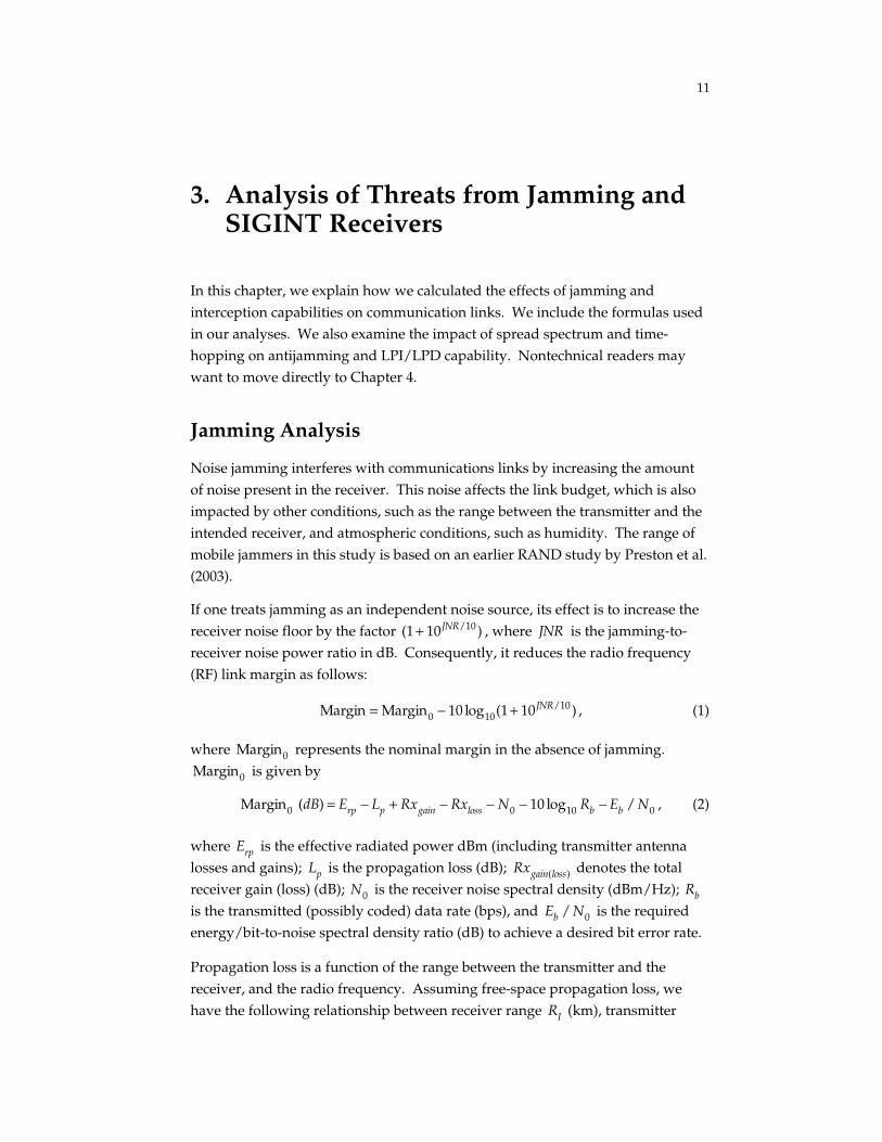
3. Analysis of Threats from Jamming andSIGINT Receivers
In this chapter, we explain how we calculated the effects of jamming andinterception capabilities on communication links. We include the formulas usedin our analyses. We also examine the impact of spread spectrum and time-hopping on antijamming and LPI/LPD capability. Nontechnical readers maywant to move directly to Chapter 4.
Jamming Analysis
Noise jamming interferes with communications links by increasing the amountof noise present in the receiver. This noise affects the link budget, which is alsoimpacted by other conditions, such as the range between the transmitter and theintended receiver, and atmospheric conditions, such as humidity. The range ofmobile jammers in this study is based on an earlier RAND study by Preston et al.(2003).
If one treats jamming as an independent noise source, its effect is to increase thereceiver noise floor by the factor (1 + 10JNR/10 ) , where JNR is the jamming-to-receiver noise power ratio in dB. Consequently, it reduces the radio frequency(RF) link margin as follows:
Margin = Margin0 − 10 log10(1 + 10JNR/10 ) , (1)
where Margin0 represents the nominal margin in the absence of jamming.
Margin0 is given by
Margin0 (dB) = Erp − Lp + Rxgain − Rxloss − N0 − 10 log10 Rb − Eb / N0 , (2)
where Erp is the effective radiated power dBm (including transmitter antennalosses and gains); Lp is the propagation loss (dB); Rxgain(loss) denotes the totalreceiver gain (loss) (dB); N0 is the receiver noise spectral density (dBm/Hz);
Rb
is the transmitted (possibly coded) data rate (bps), and Eb / N0 is the requiredenergy/bit-to-noise spectral density ratio (dB) to achieve a desired bit error rate.
Propagation loss is a function of the range between the transmitter and thereceiver, and the radio frequency. Assuming free-space propagation loss, wehave the following relationship between receiver range
RI (km), transmitter

12
power P (dBW); transmitter gain GTI (dB) (in the direction of the receiver), and
the carrier-to-noise ratio CNR (dB/Hz):
P + GTI + 30 − Lpi + Rxgain − N0 = CNR,
where Rxgain is the receiver antenna gain (dB); N0 is the receiver noise spectraldensity (-170 dBm/Hz assumed in the following);
Lpi = 92.4 + 20 log10( f ) + 20 log10(RI )
is the propagation loss between the transmitter and receiver; and f (GHz) is theoperating frequency.
In the following analysis, we focus on line-of-sight links in three frequencybands: X- (8.22 GHz), Ku- (14 GHz), and Ka- (29 GHz) band. For each link, thefollowing assumptions are made: (a) transmit/receive phased-array antennasare used, each with N elements and with 0.75 wavelength spacing betweenelements; (b) transmitter power is 125 W; (c) -170 dBm/Hz receiver noise spectrallevel is assumed; and (d) atmospheric-related attenuations are 0 dB at X-band, 1dB at Ku-band, and 4 dB at Ka-band. Based on data presented in Khatib (1997),the peak gain Gant (dB) of the transmit/receive phased-array antennas ismodeled by
Gant ≈ 9.24 + 10 log10(N ⋅ (d / λ)2 ) , (3)
where d / λ is the ratio of the array element spacing to the wavelength. Notethat
Gant enters into the nominal link margin (Eq. 2) via both Erp and Rxgain ,
and thus, for a fixed d / λ , the nominal link margin increases with increasing Nas 20 log10 N.
The corresponding link margins (relative to a nominal Eb / N0 of 12 dB) arepresented in Figures 3.1–3.3. As shown, the link margin decreases with greaterfrequency because of the additional propagation loss [increasing with frequency
f as 20 log10( f ) ] as well as the additional assumed atmospheric-relatedattenuation. Using data presented in Khatib (1997), the estimated payloadweights of the transmit/receive phased-array antennas for the differentfrequency bands and for different values of N are tabulated in Table 3.1.

13
RAND TR159-3.1
30
28
26
24
22
20
18
16
14
32
Mar
gin,
dB
12600500
N = 1024 elements
512
256
1024
512
256
Range, km
Data rate = 1.0 Gbps
400300 700
28
26
24
22
20
18
16
30
141
Data rate, Gbps
Range = 500 km
0.5 1.5
Figure 3.1—X-Band Link Margin
RAND TR159-3.2
24
22
20
18
16
14
12
10
8
26
Mar
gin,
dB
6600500
N = 1024 elements
512
256
1024
512
256
Range, km
Data rate = 1.0 Gbps
400300 700
24
20
18
16
14
12
10
26
81
Data rate, Gbps
Range = 500 km
0.5 1.5
22
Figure 3.2—Ku-Band Link Margin

14
RAND TR159-3.3
15
10
5
0
20M
argi
n, d
B
–5600500
N = 1024 elements
512
256
1024
512
256
Range, km
Data rate = 1.0 Gbps
400300 700
15
10
5
0
20
–51
Data rate, Gbps
Range = 500 km
0.5 1.5
Figure 3.3—Ka-Band Link Margin
Table 3.1
Estimated Payload Weights for a Single,N-Element Phased-Array Antenna
FrequencyBand N Weight (lb) a
250 45X1500 130
250 451500 125
Ku, Ka
2000 145
a Including controller and power supply.
To parameterize the effects of jamming on system performance, we consider theplane earth1 geometry depicted in Figure 3.4. For a given altitude H, the jammerrange
DJ is determined in terms of the elevation angle θ via DJ = H / sinθ .
_________________1 This is a good approximation over the ranges of interest here.

15
RAND TR159-3.4
X
H
θ
Receiverplatform
Jammer
DJ
Figure 3.4—Jammer Link Geometry
The received jamming-to-receiver noise power ratio JNR is given by
JNR (dB) = Jrp − LpJ + Rxgain; J − Rxloss ; J − N0 − 10 log10 Rb , (4)
where Jrp denotes the effective radiated power (dBm) from the jammer
(including transmitter antenna losses and gains); LpJ is the propagation loss (dB)from the jammer to the receiver platform;
Rxgain(loss); J denotes the total receiver
gains (losses) (dB) associated with the jammer signal; N0 is the receiver noisespectral density (dBm/Hz), and
Rb is the transmitted data rate (bps). With
reference to Figure 3.4, the propagation loss (dB) from the jammer to the receiver
LpJ can be expressed in terms of the receiver platform altitude H (km) and theelevation angle θ as
Lp = 20 log10(4πrf / c) ≈ 92.4 + 20 log10( f ) + 20 log10(H / sinθ) , (5)
where f is the frequency and c = 3 × 10⁸ m/ s is the speed of light.
Signal Detection Analysis
Detection probability is the probability that a SIGINT receiver will detect anemitter, assuming that the SIGINT receiver antenna is pointed at the emitter.The intercept probability equals detection probability × time (power on)/receiverscan time.

16
Probability of Detection (PD) Versus Received Signal Power at theReceiver
Detection, the gateway to interception, includes signal sorting and classification.SIGINT receivers can employ a variety of detectors such as (1) standardradiometers (energy detectors), (2) channelized radiometers, (3) cross-correlators,and (4) compressive receivers. As an illustration of the factors influencingdetector performance, we consider a standard radiometer as depicted inFigure 3.5.
The input signal x(t) is first filtered through a predetection filter with asufficiently wide bandwidth to accommodate the signal class of interest. Thepredetection filter bandwidth W will typically not be optimized for a givenwaveform. After predetection filtering, the data y(t) are passed through asquare-law device and are then integrated in a postdetection filter over asufficient time interval T to provide reliable signal threshold detection. Thethreshold
VT is chosen based on a desired false-alarm probability
PFA . Note that
a threshold decision can be made every T seconds. Once a signal detection isregistered, the other intercept functions are initiated.
The relevant SIGINT receiver parameters include predetection filter bandwidth
W ; integration time constant T ; detection threshold VT ; and false-alarmprobability PFA . Other parameters include the received signal power P (at theoutput of the predetection filter) as well as the receiver spectral noise densityN0 . The former depends upon the radiated source power in the direction of thereceiver; the range from the source to the receiver; the operating frequency f0 ;and the antenna gain of the receiver in the direction of the source. The receiverspectral noise density N0 is dependent upon the receiver noise figure F .
RAND TR159-3.5
x(t) y(t)BPF,
W
Noncoherent integration
Signaldetector
(.)2
k = 1, 2, ...
dt . y (t )
2,k . T
(k – 1) . TVk =⌡
⌡
Vk ≥ Vt ← signaldetection
Figure 3.5—Energy Detector

17
Assuming the receiver noise is spectrally white and Gaussian, then theprobability of signal detection
PD is given by [Torrieri, 1985]:
PD = 1
2dx ⋅ x
λ⎛⎝⎜
⎞⎠⎟
(γ −1)/2
⋅exp(− x + λ2
) ⋅ Iγ −1( xλ )2VT /N0
∞∫ , (1a)
where γ denotes the largest integer not exceeding the time-bandwidth product
T ⋅W , i.e., γ ∫ T ⋅W⎡⎢ ⎤⎥ ; Iγ −1(⋅) is the modified Bessel function of the first kind
and order γ − 1 ; λ ∫ 2 ⋅ P ⋅T / N0 is twice the intercepted signal energy-to-noisespectral density ratio, and VT / N0 can be directly related to PFA via:
PFA = exp −
VT
N0
⎛
⎝⎜⎞
⎠⎟⋅ 1
k !⋅
VT
N0
⎛
⎝⎜⎞
⎠⎟
k
k =0
γ −1∑ . (1b)
Thus, given PFA , VT / N0 can be obtained by inverting Eq. (1b).
Two limiting cases are worth noting: large T ⋅W and T ⋅W = 1. In the formercase, Vk (Figure 3.5) is approximately Gaussian and we have the approximationsfor PD and PFA [Torrieri, 1985]:
PD = 12
⋅ erfcVT / N0 − T ⋅W − λ / 2
2 ⋅ (T ⋅W + λ)
⎡
⎣⎢⎢
⎤
⎦⎥⎥
, (2a)
and
PFA = 1
2⋅ erfc
VT / N0 − T ⋅W
2 ⋅T ⋅W
⎡
⎣⎢
⎤
⎦⎥ , (2b)
where erfc(⋅) is the complementary error function defined by
erfc(x) ∫ 2
π⋅ du ⋅exp(−u2 )
x
∞∫ . (2c)
This is a reasonable approximation for detecting spread-spectrum transmissions.Given N0=170,
Ps (dBm) = CNR (dB − Hz) + N0 = CNR − 170 .
Plots of RI versus data rate are presented in Figure 3.6 for different GTI and for
CNR = 49 dB-Hz ( T = 100 sec, single-channel radiometer) and CNR = 31dB/Hz ( T = 1 sec). As is seen with a T = 1 sec radiometer integration, the linkbecomes quite vulnerable to long-range interception ( RI > 100 km) at data rateson the order of 1 Mbps once GTI exceeds -10 dB.

18
RAND TR159-3.6
100
300
Inte
rcep
t ran
ge, k
m
0
Data rate, bps
GTI = –10 dB
104 106
200
500
1000
0
Data rate, bps
GTI = 0 dB
104 106
5
10
Inte
rcep
t ran
ge, k
m
0
GTI = –40 dB
50
100
0
GTI = –20 dB
CNR = 31 dB/Hz
CNR = 49 dB/Hz
CNR = 31 dB/Hz
CNR = 49 dB/Hz
CNR = 31 dB/Hz
CNR = 49 dB/Hz
CNR = 31 dB/Hz
CNR = 49 dB/Hz
Figure 3.6—Intercept Ranges as a Function of Transmitted Data Rate
Based on the single-channel radiometer detectability analysis carried outpreviously, we consider here trade-offs between received signal level
Ps ,
predetection resolution bandwidth B , and detector integration time T = K / B ,where K = B ⋅T is the detector time-bandwidth product. In this analysis, it isassumed that the SIGINT receiver spectral noise density is a nominal N0 = –170dBm/Hz. It is further assumed that the communication link becomes vulnerableonce the detection probability PD exceeds 10-6 at a false-alarm probability
PFA of
10–8.
Given that detectability can be conveniently parameterized in terms of the signalpower-to-noise spectral density ratio CNR =
Ps / N0 at the intercept receiver,
then for a given N0 we can equivalently parameterize detector performance interms of
Ps (dBm) = CNR (dB − Hz) + N0 = CNR − 170 .

19
To compute the signal-to-noise ratio and bandwidth, we use formulas (2a), (2b),and (2c) above, which provide approximations for PD and PFA . Given PD = 10-6
and PFA = 10-8, we note that
12
⋅ erfc 3.35⎡⎣ ⎤⎦ ~ PD (3a)
and
12
⋅ erfc 3.96⎡⎣ ⎤⎦ ~ PFA . (3b)
Substituting into Eqs. (2a) and (2b), we derive the following relationship between
K , B, and CNR (valid for large K ):
K ~ 2 ⋅ 3.96 ⋅ B/CNR − 3.35 ⋅ (B/CNR) ⋅ 1 + 2 ⋅CNR / B( )2
~ 2 ⋅ 3.96 ⋅ B/CNR − 3.35 ⋅ (B/CNR) ⋅ (1 + CNR / B)( )2
= 2 ⋅ 0.61 ⋅ B/CNR − 3.35( )2,
(4)
where we make the assumption (second equality in (2a)) that CNR / B << 1(which is valid for large B ). Given Eq. (4), we can plot Ps for different values of
B and T .
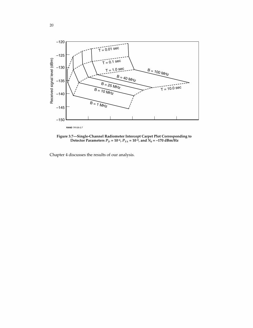
The carpet plot in Figure 3.7 corresponds to the nominal detection parameters.The predetection resolution bandwidth B is typically chosen to span the widestpossible signal bandwidth of interest. As seen in the figure, for a given T ,increasing B results in larger signal detection thresholds. For example, at T = 1sec, the minimum detectable signal level is approximately –140 dBm at B = 1MHz; however, at B = 100 MHz, the minimum detectable signal level increasesto almost –130 dBm. This illustrates the importance of spread-spectrumwaveforms, which force the SIGINT receiver to increase B and thereby degradeits signal detection threshold.
Furthermore, keeping the average transmitted message as short as possible limitsthe SIGINT receiver’s maximum effective integration time T and therefore alsodegrades its signal detection threshold. For example, at B = 1 MHz, a signaldetection threshold of approximately –145 dBm is feasible if T = 10 sec, whereasthis increases to almost –130 dBm if the SIGINT receiver is forced to reduce T toonly 10 msec (or equivalently if the average message duration is reduced to 10msec, which is possible for command/control data transmissions).
20
RAND TR159-3.7
–130
–125T = 0.01 sec
T = 0.1 sec
T = 1.0 sec B = 100 MHzB = 40 MHzB = 25 MHzB = 10 MHz
B = 1 MHz
T = 10.0 sec
–135
–140
–145
–120
Rec
eive
d si
gnal
leve
l (dB
m)
–150
Figure 3.7—Single-Channel Radiometer Intercept Carpet Plot Corresponding toDetector Parameters PD = 10–6, PFA = 10–8, and N0 = –170 dBm/Hz
Chapter 4 discusses the results of our analysis.

21
4. Options to Mitigate Jamming andIncrease LPI/LPD
Moderate jammers and SIGINT receivers are serious threats to communicationnetworks. In addition, the survivability of the entire platform can becompromised if the enemy uses SIGINT receivers to detect and locate airplatforms. To guard against these threats, it is critical to improve existingantijam and low-probability of intercept/low probability of detection (LPI/LPD)capabilities in the communications network.
In this chapter, we examine the feasibility of the following options for thesepurposes:
• Spread spectrum and frequency-hopping
• Smart antennae
• Absorption band
• Free-space laser.
The CDL Family Provides an Adequate Capacity andSome Protection Against Detection and Jamming, But ItMay Not Be Enough
As explained earlier, CDL and MP-CDL are capable of providing the data raterequired for transmitting sensor data from fighter and bomber platforms withhigh-resolution sensor capabilities. Figure 4.1 illustrates the trade-off among thedata rate, antenna size, and the range between the receiver and transmitter. Forexample, a 48-in. antenna aperture, such as the one on Global Hawk, can supportup to a 50-Mbps link from the airborne platform to a satellite. Similarly, a 9-in.aperture, similar to that on the Predator package, can support a long-range air-to-air link.
CDL family links degrade rather gracefully in a hostile jamming environment.The throughput degrades from 270 Mbps to 10 Mbps to increase the margin byabout 14 dB. This margin provides some protection against jamming, which wewill discuss. However, these links are not designed for more severe jammingenvironments or SIGINT receivers.

22
Lower-altitude platformssuch as fighters andbombers
RAND TR159-4.1
NOTE: Assumptions: 10-dB margin air-to-air link (over 12-dB Eb/N0): air CDL link (AT-100)transmit/receive antennas with 200-W radiated power; 15 GHz.
103
104
102
105
Ran
ge (
km)
101
Antenna aperture(Global Hawk)
Data rate = 200 Mbps10050
1
48”
1” (omni)
2”
8”
9.5”
Higher-altitude
platforms
10
Figure 4.1—Antenna Size, Data Rate, and Link Range Trade-Offs
Spreading the Signal Over Time and BandwidthIncreases LPI/LPD But Degrades Link Capacity
Spread-spectrum techniques produce LPI signals that are difficult to detect, read,or jam. These techniques spread the energy of the transmitted signal across afrequency band that is much wider than is normally required. This approachmakes the location of the transmitter difficult to detect.
By introducing a duty cycle (on-off transmission pattern, random or periodic),the communicator spreads its transmissions over time much like frequency-hopping or spread-spectrum modulation spreads the transmission overfrequency; this technique is known as time-hopping. If one assumes that theSIGINT receiver is not smart enough to synchronize to the transmissions, thenthe receiver is forced to integrate over a long time interval T in an attempt tocollect enough energy to determine whether or not the communicator istransmitting.
Again, this approach is analogous to spread-spectrum communications whereinthe SIGINT receiver is forced to use a wider bandwidth to collect all of thetransmitted energy from the communicator. The net effect of this is to lower theaverage intercepted power by a factor alpha, which is the ratio of totaltransmission time Ts to T, i.e.,

23
duty cycle = α = Ts/T.
Thus, the average intercepted power is reduced by alpha over what would bereceived if the communicator were transmitting continuously (at peak power).The received signal level at the SIGINT receiver is reduced by 10*(log10(alpha)).
Smart Antennae Increase Jam Resistance
Smart antenna processing reduces the effect of jamming by placing antenna nullsin the direction of the jammer to cancel its effect. Smart antenna processingsystems range from simple sidelobe cancellers to more sophisticated,multielement, phased-array antennae. In the case of sidelobe canceling, jammingenergy received through the sidelobe of the primary antenna (phased array, dish,etc.) is cancelled via an auxiliary antenna (phased array, omnidirectional antennaelement, reflector, etc.), which is (ideally) shielded from the incident jammingsignal of interest. Multielement phased arrays use adaptive beamformingnetworks to provide jammer cancellation, as noted above.
In any case, the reduction in jamming effect afforded by smart antennaprocessing depends on several factors, including platform dynamics, totalnumber of antenna elements available, and number of active jammers. Typicalairborne smart-antenna processing systems can provide an additional 20 to 60 dBof cancellation in jamming-to-receiver noise power over that provided from thesidelobe antenna gain of the primary antenna pattern.
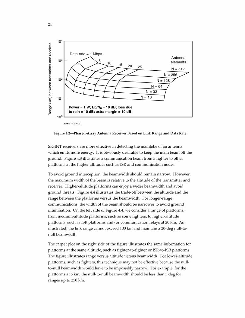
Figure 4.2 is another carpet plot illustrating the trade-offs between the size (i.e.,the number of elements in the phased-array antenna), data rate, and rangebetween transmitter and receiver. As an example, this figure illustrates how 256-element antennae at both a receiver and transmitter can support a 30-Mbps datarate up to 200 km.
LPI/LPD Antenna Design Can Protect Against SilentThreats and a Severe Jamming Environment
As discussed above, the smart antenna increases antijam capability. However, itdoes not provide protection against SIGINT receivers such as a standardradiometer (energy detector). This problem can be addressed through antennadesigns aimed at lowering the signal received by a SIGINT receiver. Theprobability of detection can be substantially decreased by reducing power andsidelobes.
24
RAND TR159-4.2
Power = 1 W; Eb/N0 = 10 dB; loss dueto rain = 10 dB; extra margin = 10 dB
103
102
101
104
Ran
ge (
km)
betw
een
tran
smitt
er a
nd r
ecei
ver
100
N = 512
N = 256
N = 16
N = 32N = 64
N = 128
Data rate = 1 Mbps
20 251510
5Antennaelements
Figure 4.2—Phased-Array Antenna Receiver Based on Link Range and Data Rate
SIGINT receivers are more effective in detecting the mainlobe of an antenna,which emits more energy. It is obviously desirable to keep the main beam off theground. Figure 4.3 illustrates a communication beam from a fighter to otherplatforms at the higher altitudes such as ISR and communication nodes.
To avoid ground interception, the beamwidth should remain narrow. However,the maximum width of the beam is relative to the altitude of the transmitter andreceiver. Higher-altitude platforms can enjoy a wider beamwidth and avoidground threats. Figure 4.4 illustrates the trade-off between the altitude and therange between the platforms versus the beamwidth. For longer-rangecommunications, the width of the beam should be narrower to avoid groundillumination. On the left side of Figure 4.4, we consider a range of platforms,from medium-altitude platforms, such as some fighters, to higher-altitudeplatforms, such as ISR platforms and/or communication relays at 20 km. Asillustrated, the link range cannot exceed 100 km and maintain a 20-deg null-to-null beamwidth.
The carpet plot on the right side of the figure illustrates the same information forplatforms at the same altitude, such as fighter-to-fighter or ISR-to-ISR platforms.The figure illustrates range versus altitude versus beamwidth. For lower-altitudeplatforms, such as fighters, this technique may not be effective because the null-to-null beamwidth would have to be impossibly narrow. For example, for theplatforms at 6 km, the null-to-null beamwidth should be less than 3 deg forranges up to 250 km.

25
RAND TR159-4.3
Fighter
Interceptor
Receiver
Sidelobeantenna
gain
Mainlobe
Transmitter
Effective radiatedpower (interceptor)
Effective radiatedpower (receiver)
Figure 4.3—Protecting Against Silent Threat
RAND TR159-4.4
30
15
10
5
35
Nul
l-to-
null
beam
wid
th (
deg)
Nul
l-to-
null
beam
wid
th (
deg)
0200160
10
20
250
100
250
6
Altitude =2 km
Range =1 km
Line-of-sight range, r (km)
6 km to 20 km
Range vs. beamwidthPlatform altitude vs.range vs. beamwidth
12080 280
25
20
240
9
8
7
4
10
0
Same altitude
6
5
3
2
1
Figure 4.4—Maximum Beamwidth Allowable for Keeping the Main Beam Off theGround
Outside the main beam of the antennae are the sidelobes, which are anundesirable—but unavoidable—feature, especially in this case. Sidelobes have to

26
be suppressed as much as possible; however, suppressing sidelobes usuallydegrades antenna efficiency and increases the beamwidth. Thus, to maintainhigh gain in the mainlobe and keep the beamwidth narrow, the antenna size hasto be increased (Georgia Institute of Technology, 1993). Figure 4.5 illustrates thetrade-off between beamwidth sidelobe and antenna size. The figure indicatesthat a 20-deg null-to-null corresponds to a 21-in. antenna diameter for a 48-dBsidelobe reduction.
Spread-Spectrum, Low-Power, Low-SidelobeTechniques Can Be Combined for IntratheaterPlatforms
Our analysis to evaluate the adequacy of current systems in a severe jammingenvironment found that the current systems are not adequate for robustcommunications. To address the challenges posed by a more severe jammingenvironment, a combination of spread spectrum and phased-array antennas withnulling capabilities will be required.
The options we have discussed can help reduce vulnerabilities in thecommunications network, but each option has its unique limitations. Spreadspectrum alone does not protect against more-advanced jammers. Becausespread-spectrum techniques use a high percentage of bandwidth, thesetechniques are not very useful for higher data rates. Antijam capabilities can beincreased by increasing the effective radiated power, but LPI/LPD will bediminished as a result.
Maintaining the balance between antenna power and LPI/LPD requires acombination of directionality, power management, and low sidelobes. The firstoption for achieving LPD is to decrease the antenna's effective radiated power(ERP) in the direction of energy detectors. However, because SIGINT receiverthreats are hard to locate, it will also be necessary to keep the mainlobe off theground (in case of ground threats) and reduce the sidelobes. This technique isuseful primarily for platforms at altitudes of 12 km and above. Using differenttypes of tapers can reduce the antenna sidelobe. However, the use of tapers willincrease antenna size while decreasing its efficiency. For example, a 256-elementantenna on both receiver and transmitter can support 10-Mbps data rate at arange of 250 km. However, to reduce sidelobes sufficiently to maintain an"acceptable" protection against energy detectors, a much larger antenna would beneeded. In this example, a 512-element antenna would be required to achieve a25-dB (from the peak mainlobe) gain reduction in sidelobes (using Blackmantaper) while maintaining a null-null 20-deg beamwidth.

27
RAND TR159-4.5
40
Antenna size vs. sidelobereduction vs. bandwidth60
50
30
20
10
70
Nul
l-to-
null
beam
wid
th (
deg)
0
6”
24”
13.2
48
Sidelobe reduction (dB)
4032
23
21”18”
15”
12”
9” Antennasize
Figure 4.5—Suppressing Sidelobe Increases Antenna Size
The carpet plot in Figure 4.6 illustrates the trade-offs between three parameters:(1) range or distance between the SIGINT receiver and the transmitter, (2) ERP inthe direction of the SIGINT receiver, and (3) SIGINT receiver sensitivity, rangingfrom very moderate current receivers with –50-dBm sensitivity to very advancedreceivers with –140 dBm.
A moderate SIGINT receiver can easily detect a Global Hawk-type antenna withan ERP of 70 dBm at the mainlobe. As is illustrated in Figure 4.6, a moderatereceiver can easily detect this type of antenna even from its sidelobes (with –50-dBm sensitivity). Suppressing the sidelobes, however, decreases the receivedsignal at the SIGINT receiver. A current state-of-the-art SIGINT receiver (with–100-dBm sensitivity) would still be able to intercept such a signal. Additionalspreading and time-hopping reduces the signal effectiveness at the SIGINTreceiver.
The current CDL program, which uses a parabolic dish, can be susceptible tosevere jamming. Although a comparable parabolic antenna dish can support thesame link, it may not provide the required jamming protection. We thereforeexamined the levels of protection provided by different antenna options againstvarious mobile jammers.

28
RAND TR159-4.6
Received signal at the interceptor vs. interceptorrange and interceptor sensitivity
102
101
103S
IGIN
T r
ecei
ver-
to-t
rans
mitt
er r
ange
(km
)
100
ReceiverERP =
70 dBm
Combiningtechniques:
low sidelobes,spread spectrum,and time-hopping
Lowsidelobe
9”parabolicsidelobe
dish
50
4540
–50 dBm
(interceptor sensitivity)
–70 –90
–110
–130
–140
30
20
10
Figure 4.6—Transmitter ERP in the Direction of SIGINT Receiver vs. InterceptSensitivity and Range
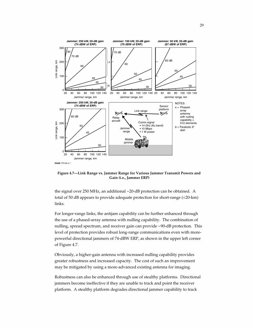
Figure 4.7 illustrates link range versus jammer range. Four levels of jammingthreats are analyzed, from more severe in the upper left corner to less severe inthe lower left corner.1 The analysis assumed that stationary ground jammerscould be detected and destroyed. In the figure, a 30-dB protection linecorresponds to a 512-element receiver antenna gain (in the direction oftransmitter).
As demonstrated in the lower left corner of the figure, without furtherprotection, a moderate mobile jammer (63 dBW) would be capable of jamming alink even from a long range. As we explained earlier, spread-spectrumtechniques can provide additional protection against jamming; however, theyalso degrade link capacity. By reducing the data rate to 2 MHz and spreading
_________________1 Platforms are considered to be operating at 20-km altitude at Ku-band with 10-dB rain
attenuation. Transmitter ERP is 30 dB (corresponding to 512 elements), 20-dB jammer antenna gain,10-mbps data rate, 18-dB link SNR (corresponding to a 6-dB margin over Eb/No = 12 dB).
29
RAND TR159-4.7
200
100
0
300
Link
ran
ge, k
m
12060
70 dB
90
30
45
50
60
Jammer range, km
Jammer: 250 kW, 20-dB gain(74 dBW of ERP)
4020 14010080
200
100
0
300
Link
ran
ge, k
m
12060
60 dB
30
45
50
Jammer range, km
Jammer: 250 kW, 20-dB gain(74 dBW of ERP)
4020 14010080
12060
70 dB
30
45
50
60
Jammer range, km
Jammer: 100 kW, 20-dB gain(70 dBW of ERP)
4020 14010080 12060
60 dB
30
45
50
Jammer range, km
Jammer: 50 kW, 20-dB gain(67 dBW of ERP)
4020 14010080
A
B
NOTES:A = Phased- array antenna with nulling capability = 512 elementsB = Parabolic 9” dish
Relayaircraft
SensorplatformLink range
Jammerrange
Mobilejammer
Comm signal • 14 Ghz (Ku band) • 10 Mbps • 1 W power
Figure 4.7—Link Range vs. Jammer Range for Various Jammer Transmit Powers andGain (i.e., Jammer ERP)
the signal over 250 MHz, an additional ~20-dB protection can be obtained. Atotal of 50 dB appears to provide adequate protection for short-range (<20-km)links.
For longer-range links, the antijam capability can be further enhanced throughthe use of a phased-array antenna with nulling capability. The combination ofnulling, spread spectrum, and receiver gain can provide ~90-dB protection. Thislevel of protection provides robust long-range communications even with more-powerful directional jammers of 74-dBW ERP, as shown in the upper left cornerof Figure 4.7.
Obviously, a higher-gain antenna with increased nulling capability providesgreater robustness and increased capacity. The cost of such an improvementmay be mitigated by using a more-advanced existing antenna for imaging.
Robustness can also be enhanced through use of stealthy platforms. Directionaljammers become ineffective if they are unable to track and point the receiverplatform. A stealthy platform degrades directional jammer capability to track

30
and point and hence degrades their effectiveness. Further analysis is required toexamine the effectiveness of this option.
Absorption Band Is a Viable Option for the BackboneNetwork But Not for Long-Range Intratheater Links
Communications in the absorption band [55–65 GHz] provide a widerbandwidth but also provide substantial atmospheric attenuation of a ground-based jamming threat when the air platforms are operating at high altitudes (i.e.,20 km or greater).
Atmospheric absorption makes the absorption band very unattractive forcommunication links in the troposphere. The atmospheric attenuation at 10 kmis about 10 times higher (i.e., 4–5 dB/km) than that at 20 km. As a consequence,the integrated attenuation for the link accumulates much faster than it does forthe higher-altitude backbone links, thus making use of the absorption bandimpractical for long-range links.
A Laser Communication System Is the Most RobustLink Above the Cloud Level
So far, we have focused on improving capacity and providing antijammingprotection for communications links using radio frequencies. However, thehigh carrier frequency and bandwidth potential of laser optics offers severalpotential advantages over RF links: much higher data rates, reducedpayload weights and power consumption, increased covertness, and reducedvulnerability to jamming. Optical links can also operate in parallel with otherassets, because they do not use the same allocated and regulated spectrum asRF communications. Laser optics efficiently and simultaneously transfermultiple wideband channels and allow the data to be encoded, decoded, androuted to many users via a single transceiver system. Laser optics are ofparticular interest to military users because of their narrow transmit beams,which have very low sidelobe levels and thereby provide a very low probabilityof intercept.
Optical links have a number of disadvantages, however. A fundamentalproblem is that rain and clouds, which absorb laser beams, significantly degradecommunications. Because cloud formation is usually limited to altitudes below12 km, absorption is less of a problem for high-altitude platforms. Anotherconcern is that the highly directed transmit beams coupled with the vibration of

31
satellites and platforms pose difficulties in tracking, acquiring, and maintainingthe link.
These limitations might be overcome through a combination of laser opticstechnology and RF technologies capable of increasing covert high-data-ratecommunications. The RF technology could be used to receive and transmitcommunications to a ground station in the presence of clouds, and laser opticscould be used for high-altitude (above the cloud level) air-to-air, air-to-satellite,and satellite-to-satellite and air- or satellite-to-ground links in dry climates.Although laser optic technology is still in development and therefore posesimplementation risks, there is evidence that these problems may be resolved inthe near future. The Optical Communications Technology group at LincolnLaboratory has been developing the system concepts and space-qualifiedhardware to build a package that could support high-data-rate optical links.Based on their results, the group concluded that the current technology is readyfor an operational system with a satellite-to-satellite link capability of severalhundred megabits per second, and that this number would increase to multiplegigabits in the near future.2
A congressionally mandated and funded program known as the Recce.IntelLaser Crosslink Program started in 1996 with the objective of demonstrating fullduplex air-to-air lasercom using autonomous signal acquisition and trackingwith the terminal and other hardware. AFRL has estimated an operational UAVoptical terminal at less than 150 lbs.
________________2 Interview with Roy Bondurant at Massachusetts Institute of Technology, Cambridge, MA,
2002; and with Hamid Hemmati at Jet Propulsion Laboratory, Pasadena, CA, 2002. See also Hemmati(2002).

33
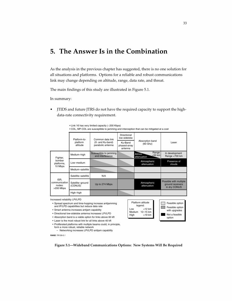
5. The Answer Is in the Combination
As the analysis in the previous chapter has suggested, there is no one solution forall situations and platforms. Options for a reliable and robust communicationslink may change depending on altitude, range, data rate, and threat.
The main findings of this study are illustrated in Figure 5.1.
In summary:
• JTIDS and future JTRS do not have the required capacity to support the high-data-rate connectivity requirement.
Fighter,bomber
platforms,10 Mbps
ISR,communication
nodes:>200 Mbps
Increased reliability LPI/LPD
• Spread spectrum and time-hopping increase antijamming and IP/LPD capabilities but reduce data rate
• Smart antenna increases antijam capability
• Directional low-sidelobe antenna increases LPI/LPD
• Absorption band is a viable option for links above 60 kft
• Laser is the most robust link for all links above 40 kft
• Proliferated platforms with multiple beams could, in principle, form a more robust, reliable network
– Networking increases LPI/LPD antijam capability
LowMediumHigh
Platform altitudelegend:
<12 km12–15 km
>19 km
Medium–high
Low–medium
Medium–satellite
Satellite–satellite
Satellite–ground(CONUS)
High–high
Platform-to-platform altitude
Common data link(X- and Ku-band)parabolic antenna
Directionallow sidelobe
Ku-Bandphased-array
antenna
Absorption band(60 Ghz) Laser
In developmentRange <700 km
• Link 16 has very limited capacity (~200 Kbps)• CDL, MP-CDL are susceptible to jamming and interception that can be mitigated at a cost
RAND TR159-5.1
Feasible option
Feasible optionwith upgrades
Not a feasibleoption
N/A
Susceptible to jammingand interference
Up to 274 Mbps Atmosphericattenuation
Atmosphericattenuation
Possible with multipleground receivers
in dry CONUS
Presence ofclouds
Atmos.attenuation
Range<50 km
Figure 5.1—Wideband Communications Options: New Systems Will Be Required

34
• CDL-family programs can provide a sufficient data rate for thefighter/bomber with Advanced Synthetic Aperture Radar System(ASARS)–Improved Program (AIP) capability. However, these systems needfurther improvement to survive a severe threat environment.— Spread spectrum can provide some protection against jamming, but it
reduces the data rate.— A near-term solution for improving jam resistance is to add nulling
capability to CDL families (including MP-CDL). However, althoughnulling techniques are effective for jammers, they are not effectiveagainst SIGINT receivers such as energy detectors.
— Agile, multibeam, low-sidelobe directional antennae are required toachieve more protection against jamming and SIGINT receivers. Thesetechniques increase the size and weight of the antenna.
• High-altitude platforms, such as ISR platforms, communication nodes andsatellites, have two communications options:— This absorption band is a viable option for links above 60,000 ft (ISR
and communication nodes).— Laser is the most robust option for links above 40,000 ft.
• Proliferated platforms with multiple beams, in principle, may form a morerobust, reliable network. Further analysis is required to examine theeffectiveness of such platforms.
Thus, communication does not appear to be a major limiting factor, at least nottechnically, in developing future ISR forces. However, programmatic action willbe required to develop the necessary systems, and the costs could be significant.The communications problems posed by future ISR forces appear solvable, but ata cost.

35
Bibliography
Georgia Institute of Technology, Antenna Engineering Handbook, Richard C.Johnson and Henry Jasik (eds.), 1st ed., New York: McGraw-Hill, Inc., 1993.
Hemmati, Hamid, Status of Free-Space Optical Communications Program at JPL,Pasadena, Calif.: Jet Propulsion Laboratory, 2000.
Joint Tactical Radio System (JTRS), accessed online at http://jtrs.army.mil/
Khatib, H. H., “Theater Wideband Communications,” 1997 MILCOM Proceedings,November 2–5, 1997, pp. 378–382.
Preston, Bob, Rosalind Lewis, David Frelinger, and Alexander Hou, Protecting theMilitary Utility of U.S. Space Systems, Santa Monica, Calif.: RAND Corporation,MR-1512-AF, 2003 (document not available to the general public).
Systems Description Document for the Common Data Link System, May 4, 1998.
Systems Requirement Document for the Multi-Platform Common Data Link System,June 11, 2002.
Torrieri, D., Principles of Secure Communication Systems, Dedham, Mass.: ArtechHouse, 1985.