Support Material Beam Clamps Pg. 154 - MP Husky · Hold Down Clamp HP-514A-PW GHP-514-PW Expansion...
14
For more information or to order, call 1-800-277-4810 or visit www.MP Husky.com. Support Material Hold Down Clamps & Expansion Guides Pgs. 148-150 Tray Hanger clips Pg. 151 Suspension Channels and Fittings Pgs. 152-153 Beam Clamps Pg. 154 Hangers Pg. 155 Supports Pgs. 156-157 Brackets Pgs. 158-160
Transcript of Support Material Beam Clamps Pg. 154 - MP Husky · Hold Down Clamp HP-514A-PW GHP-514-PW Expansion...

11.147
For more information or to order, call 1-800-277-4810 or visit www.MP Husky.com.
SupportMaterial
Hold Down Clamps & Expansion Guides Pgs. 148-150Tray Hanger clips Pg. 151Suspension Channels and Fittings Pgs. 152-153Beam Clamps Pg. 154Hangers Pg. 155Supports Pgs. 156-157Brackets Pgs. 158-160

12-S
up
po
rt
Mat
er
ial
8 6 4 . 2 3 4 . 4 8 0 0m p h u s k y . c o m
Copyright 2010 MP Husky. All rights reserved.
CABLE TRAY
148
Hold Down Clips
Single Hold Down/Expansion Clips for Flange-In Trough or LadderThis clip holds flange in trays securely to a lower support channel or bracket and can also be used as an expansion guide with a W-12 washer placed under the base. (W-12 washer sold separately) Use 1/2” hardware.
SiderailHeight
TrayType
Mill-Galv.
SS304
SS316
HDGAF Galvann.(Husky Way)
3-3/8” H,NSH0,PSH0,ASH6 HB-2 4HB-2 6HB-2 GHB-2 NHB-2
4” J,NSJ0,PSJ0,ASJ6 JB-2 4JB-2 6JB-2 GJB-2 NJB-2
4-1/2” JA,JB,JC,YA,YD KB-2 4KB-2 6KB-2 GKB-2 n/a
6” M,MB,MD,X,X1,XA,NSM0, PSM0,ASM6
MB-2 4MB-2 6MB-2 GMB-2 NMB-2
6-1/4” XB,XC,XD XCB-2 4XCB-2 6XB-2 GXCB-2 n/a
7” MD7,MD74,X7,X71,XC7,XB7 X7B-2 4X7B-2 6X7B-2 GX7B-2 n/a
Single Hold Down Clips for Flange-In This clip holds all Husky ladders to a support channel or bracket.
TrayType
ZincPlated
SS304
SS316 HDGAF
Flange In3/8” Hdw
SHDC-V 4HDC-V 6HDC-V GHDC-V
Flange In1/2” Hdw
SHDC-V1/2 4HDC-V1/2 6HDC-V1/2 GHDC-V1/2
*All part numbers are for 1 each.
Single Hold Down Clips for Flange-Out or I-Beam LadderThis clip holds Husky Ladder trays securely to a lower support channel or bracket. Use 1/2” hardware.
Hold Down/Expansion Guide for Flange Out LadderThese special heavy duty tray hold down clamps and expansion guides are ideal for fas-tening tray to C-Channels, such as those found on bridges. They are easy to install and reduce field labor costs since the beam clamp set screw eliminates the need to drill the C-Channel.
All Flange Out Ladders Zinc Plated HDGAF
Hold Down Clamp HP-514A-PW GHP-514-PW
Expansion Guide HP-514A-PWO GHP-514-PWO
TrayType
Aluminum ZincPlated
SS304
SS316 HDGAF
All Flange Out
AHDC-A SHDC-A 4HDC-A 6HDC-A GHDC-A
Hardware not included.

12-Su
pp
or
t M
ater
ial
CABLE TRAY
8 6 4 . 2 3 4 . 4 8 0 0m p h u s k y . c o m
Copyright 2010 MP Husky. All rights reserved.149
Hold Down Clips
Double Hold Down Clips for Ladder and TroughDouble hold down clips allow two side by side trays to be fastened to the support with one clip and less hardware. Use 1/2” hardware.
Hold Down Bolts for ChannelSpecial 3/8” bolts are used to fasten 4” & 6” wide Husky channels to channel hangers and other supports.
TrayType Alum.
ZincPlated
SS304
SS316 HDGAF
3/4” AHDC-2A SHDC-2A 4HDC-2A 6HDC-2A GHC-2A
1-1/2” AHDC-2CA SHDC-2CA 4HDC-2CA 6HDC-2CA GHDC-2CA
1-3/4” AHDC-2C SHDC-2C 4HDC-2C 6HDC-2C GHDC-2C
ZincPlated HDGAF
Catalog No. HB-10 GHB-10
TrayType Alum.
ZincPlated
SS304
SS316 HDGAF
All Flange In (except I8)Husky Tray
AEXG-VL SEXG-VL 4EXG-VL 6EXG-VL GEXG-VL
All Flange Out & I-BeamHusky Tray
AEXG-EL SEXG-EL 4EXG-EL 6EXG-EL GEXG-EL
*All part numbers are for 1 each.
Guides for LadderExpansion guides are used to secure ladder style trays, while guiding the tray during movement during thermal expan-sion. For expansion guide recommendations, contact your local representative or the factory. Use 1/2” hardware.
Nylon PadCatalog #INSL-VEUsed for insulating hold-downs and for insulating tray.
12-S
up
po
rt
Mat
er
ial
8 6 4 . 2 3 4 . 4 8 0 0m p h u s k y . c o m
Copyright 2010 MP Husky. All rights reserved.
CABLE TRAY Expansion Guides
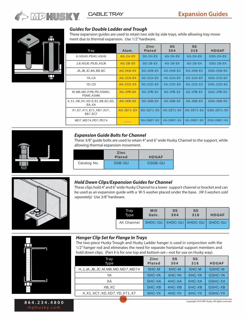
Guides for Double Ladder and TroughThese expansion guides are used to retain two side by side trays, while allowing tray move-ment due to thermal expansion. Use 1/2” hardware.
Hold Down Clips/Expansion Guides for ChannelThese clips hold 4” and 6” wide Husky Channel to a lower support channel or bracket and can be used as an expansion guide with a W-5 washer placed under the base. (W-5 washers sold separately) Use 3/8” hardware.
TrayType
MillGalv.
SS304
SS316 HDGAF
All Channel SHDC-GU 4HDC-GU 6HDC-GU GHDC-GU
Expansion Guide Bolts for ChannelThese 3/8” guide bolts are used to retain 4” and 6” wide Husky Channel to the support, while allowing thermal expansion movement.
ZincPlated HDGAF
Catalog No. SGB-GU GSGB-GU
Tray Alum.Zinc
PlatedSS
304SS
316 HDGAFH,NSH0,PSH0,ASH6 AG-2H-EX SG-2H-EX 4G-2H-EX 6G-2H-EX GSG-2H-EX
J,B,NSJ0,PSJ0,ASJ6 AG-2B-EX SG-2B-EX 4G-2B-EX 6G-2B-EX GSG-2B-EX
JA,JB,JC,BA,BB,BC AG-2KB-EX SG-2KB-EX 4G-2KB-EX 6G-2KB-EX GSG-2KB-EX
YA,CA AG-2CA-EX SG-2CA-EX 4G-2CA-EX 6G-2CA-EX GSG-2CA-EX
YD,CD AG-2CD-EX SG-2CD-EX 4G-2CD-EX 6G-2CD-EX GSG-2CD-EX
M,MB,MD,P,PB,PD,NSMO,PSM0,ASM6
AG-2PB-EX SG-2PB-EX 4G-2PB-EX 6G-2PB-EX GSG-2PB-EX
X,X1,XB,XC,XD,E,E1,EB,EC,ED, EA,XA
AG-2EB-EX SG-2EB-EX 4G-2EB-EX 6G-2EB-EX GSG-2EB-EX
X7,E7,X71,E71,XB7,XC7, EB7,EC7
AG-2E71-EX SG-2E71-EX 4G-2E71-EX 6G-2E71-EX GSG-2E71-EX
MD7,MD74,PD7,PD74 ____ SG-2MD7-EX 4G-2MD7-EX 6G-2MD7-EX GSG-2MD7-EX
Hanger Clip Set for Flange In TraysThe two-piece Husky Trough and Husky Ladder hanger is used in conjunction with the 1/2” hanger rod and eliminates the need for separate horizontal support members and hold down clips. (Part # is for one top and bottom set—not for use on Husky way).
TrayType
ZincPlated
SS304
SS316 HDGAF
H,J,JA,JB,JC,M,MB,MD,MD7,MD74 SHC-M 4HC-M 6HC-M GSHC-MYA SHC-YA 4HC-YA 6HC-YA GSHC-YAXA SHC-XA 4HC-XA 6HC-XA GSHC-XA
XB,XC SHC-XB 4HC-XB 6HC-XB GSHC-XBX,X1,XC7,XD,XD7,YD,X71,X7 SHC-YX 4HC-YX 6HC-YX GSHC-YX
150

12-Su
pp
or
t M
ater
ial
CABLE TRAY
8 6 4 . 2 3 4 . 4 8 0 0m p h u s k y . c o m
Copyright 2010 MP Husky. All rights reserved.151
Hanger Clips
I-Beam Tray HangerTray hanger for 1-1/4” and 2” flange I-Beam Trays (not for I6 & I8). Includes top and bot-tom clamps and spacer. Hanger rod, washers and hex nuts purchased seperately.
TrayType
ZincPlated
SS304
SS316 HDGAF
IJA,IJB,IJC SHC-IJA 4HC-IJA 6HC-IJA GSHC-IJA
IYB,IYC SHC-IYC 4HC-IYC 6HC-IYC GSHC-IYC
IMB,IMC,IMD,IXA,IXB,IXC,IXD SHC-IXB 4HC-IXB 6HC-IXB GSHC-IXB
IXD7 SHC-IXD7 4HC-IXD7 6HC-IXD7 GSHC-IXD7
Single Hanger Clips for Flange-Out TraysTwo inch wide single hanger clips are used with the 1/2” hanger rod to hold Husky Lad-der firmly in place.
Double Hanger ClipsDouble hanger clips are used in the center of two side by side ladders and help with a 1/2” hanger rod. The top bolt is included with each unit.
*Above part numbers are for 1 each.
TrayType Alum.
ZincPlated
SS304
SS316 HDGAF
B —— SHC-CB 4HC-CB 6HC-CB GSHC-CB
BA,BB,BC AHC-KB SHC-KB 4HC-KB 6HC-KB GSHC-KB
CA AHC-CA SHC-CA 4HC-CA 6HC-CA GSHC-CA
CD —— SHC-CD 4HC-CD 6HC-CD GSHC-CDP,PB,E,EA,E1 AHC-EP SHC-EP 4HC-EP 6HC-EP GSHC-EP
EB,EC,ED AHC-EB SHC-EB 4HC-EB 6HC-EB GSHC-EB
E7,E71,EB7,EC7 AHC-E71 SHC-E71 4HC-E71 6HC-E71 GSHC-E71
PD7,PD74 ---- SHC-PD7 4HC-PD7 6HC-PD7 GSHC-MD7
TrayType Alum.
ZincPlated
SS304
SS316 HDGAF
B —— SHC-2B 4HC-2B 6HC-2B GSHC-2B
BA,BB,BC AHC-2KB SHC-2KB 4HC-2KB 6HC-2KB GSHC-2KB
CA AHC-2CA SHC-2CA 4HC-2CA 6HC-2CA GSHC-2CA
CD —— SHC-2CD 4HC-2CD 6HC-2CD GSHC-2CD
P,PB AHC-2P SHC-2P 4HC-2P 6HC-2P GSHC-2P
E,EA,E1 AHC-2E SHC-2E 4HC-2E 6HC-2E GSHC-2E
EB,EC,ED AHC-2EB SHC-2EB 4HC-2EB 6HC-2EB GSHC-2EB
E7,E71,EB7,EC7 AHC-2E71 SHC-2E71 4HC-2E71 6HC-2E71 GSHC-2E71
PD7,PD74 —— SHC-2PD7 4HC-2PD7 6HC-2PD7 GSHC-2PD7

12-S
up
po
rt
Mat
er
ial
8 6 4 . 2 3 4 . 4 8 0 0m p h u s k y . c o m
Copyright 2010 MP Husky. All rights reserved.
CABLE TRAY
152
Suspension Channels and Fittings
Channels are used with 1/2” hanger rods to support ladder style trays where hanger clips cannot be utilized and for troughs with or without hold-down clips. When used with trough, only HB-2,JB-2, etc. style hold-down clips can be used.
Center Support( ) = insert width
Hanger Rods
Trapeze Support Channels
Item Plated Steel Stainless 316
12’0” Hanger Rod6’0” Hanger Rod3’-0” Hanger RodExtra Hex Nuts
Extra Lock WashersExtra Flat Washers
HR-144GHR-72GHR-36G
N-12W-9W-12
6HR-144G6HR-72G6HR-36GN-12-6SW-9-6SW-12-6S
Tray Width Aluminum HDGAF SS304 SS316
36”30”24”18”12”9”6”
ASC-36ASC-30ASC-24ASC-18ASC-12ASC-9ASC-6
SSC-36SSC-30SSC-24SSC-18SSC-12SSC-9SSC-6
4SC-364SC-304SC-244SC-184SC-124SC-94SC-6
6SC-366SC-306SC-246SC-186SC-126SC-96SC-6
1/2” diameter, 13 threads per inch hanger rods can be used with all tray support chan-nels, angles and hanger clips. They have continuous threads and are furnished with 4 (N-12) nuts, 2 (W-9) lock-washers and 2 (W-12) flat washers.
Maximum allowable load:Use for design, 1100 lbs., in combination with all standard suspension fittings, hanger clips, and couplings normally used. The safe load is much higher.
TrayType Aluminum HDGAF
SS316
LadderAll Flange In
All Flange OutVACS-( )EACS-( )
VSCS-( )ESCS-( )
6VSCS-( )6ESCS-( )
Husky TroughHJ
JA,JB,JC,YA,MD7,MD74M,MB,MC
----
VACS-( )-KVACS-( )-M
VSCS-( )-HVSCS-( )-JVSCS-( )-KVSCS-( )-M
6VSCS-( )-H6VSCS-( )-J6VSCS-( )-K6VSCS-( )-M

12-Su
pp
or
t M
ater
ial
CABLE TRAY
8 6 4 . 2 3 4 . 4 8 0 0m p h u s k y . c o m
Copyright 2010 MP Husky. All rights reserved.153
Suspension Channels and Fittings
Angles are continuously slotted to hold down Husky Trough using HB-1 bolts, and can be used to support all tray types with 1/2” hanger rod suspended from overhead.
Maximum allowable load:Will safely support any loaded tray of the designated width within the load limits of the hanger rod.
Single channel hangers are used to support single 4” or 6” wide Husky Channels from 1/2” hanger rod. The bottom support member, on which the channel rests, is drilled to accom-modate HB-10 hold-down bolts, or SGB-GU expansion guide bolts.
Double hangers support single or double, 4” or 6” wide Husky Channels from 1/2” hanger rods. The support member, on which the channel rests, is drilled to accommodate HB-10 hold-down bolts, or SGB-GU expansion guide bolts.
Trapeze Support Angles
Single Channel Hangers
Double Channel Hangers
Tray Width HDGAF
36”30”24”18”12”9”6”
STSA-36STSA-30STSA-24STSA-18STSA-12STSA-9STSA-6
Channel Type
HDGAF SS 304 SS 316
4”,6” SH-GU 4SH-GU 6SH-GU
Hanger Rod CouplingsCouplings are used to connect hanger rods when lengths of more that 144” are encoun-tered or to connect rods between trays that are hung one over the other. They also reduce field labor costs by extending new or existing hanger rods to support additional trays.
Channel Type
HDGAF SS 304 SS 316
4” SH-2G4 4SH-2G4 6SH-2G4
6” SH-2G6 4SH-2G6 6SH-2G6
Item Plated SS 304 SS 316
1/2” Steel w/o Window HRC 4HRC 6HRC
1/2” Malleable Ironwith Window
HRC-G -- --

12-S
up
po
rt
Mat
er
ial
8 6 4 . 2 3 4 . 4 8 0 0m p h u s k y . c o m
Copyright 2010 MP Husky. All rights reserved.
CABLE TRAY
154
Clamps
Swivel JointsSwivel joints allow hanger rods to swing from an inclined clamp. They are furnished with or without a 1 inch stud assembly.
Item PlatedSS
304SS
316Swivel Joint
OnlySJ 4SJ 6SJ
Swivel JointWith Stud
SJS 4SJS 6SJS
This wide-flanged clamp is furnished with or without a hook bolt in lengths to accom-modate 6” through 12” wide beams up to 3/4” thick.
Maximum allowable load:300 lbs.
I-Beam Clamp
Item Plated Steel SS 316
Clamp OnlyClamp w/Hook BoltLess than 6”6”-10”10”-12”
PS-2622
PS-2622-6PS-2622-10PS-2622-12
6PS-2622
6PS-2622-66PS-2622-106PS-2622-12
Beam clamps have 1/2” holes to at-tach hanger rods to a beam flange or to support channels. Furnished in unfinished iron.
Maximum allowable load:1000 lbs.
Beam Clamps
Flange Thickness Catalog No.
7/8”2”
SC-503SC-508
C-Clamps allow for the direct support of hanger rods on I-beams, wide flange beam sec-tions and angles and are sup-plied in unfinished iron.
Beam C-Clamps
Catalog No.
GC
This is standard I-Beam Clamp with a hook bolt and swivel clevis.
Maximum allowable load:300 lbs.
I-Beam Clamp w/Swivel
Item Plated Steel SS 316
Clamp OnlyClamp w/Hook BoltLess than 6”6”-10”10”-12”
PS-2622SJ
PS-2622SJ-6PS-2622SJ-10PS-2622SJ-12
6PS-2622SJ
6PS-2622SJ-66PS-2622SJ-106PS-2622SJ-12

12-Su
pp
or
t M
ater
ial
CABLE TRAY
8 6 4 . 2 3 4 . 4 8 0 0m p h u s k y . c o m
Copyright 2010 MP Husky. All rights reserved.155
Hangers
The standard size is 1-1/4” square with a 1/2” bevel and a 9/16” hole. Bolt and nut not in-cluded.
Bevel Washers
Catalog No.
W-11
Vertical Hangers For Tray
Vertical Hangers For Channel
Vertical hangers support single-type vertical ladders or troughs from 1/2” hanger rods. Each is furnished with the required mounting hardware.
Maximum allowable load:250 lbs. per unit
HDGAF SH-VU
SS 316 6SH-VU
This hanger assembly for vertical channels accommo-dates either 4” or 6” wide channels and is furnished with all necessary hardware, except for the top 1/2” hanger rod to the building steel.
Maximum allowable load:200 lbs.
HDGAF SH-VGU
SS 316 6SH-VGU
Channel ClampsChannel clamp assemblies can be used on all American Standard channels with a flange width of 3-1/4” or less. They are furnished in zinc plated steel with or without a swivel joint.
Maximum allowable load:500 lbs. with a safety factor of 5
Item Zinc Plated Steel
Clamp Only HP-177
Clamp w/Swivel Joint HP-177SJ
HP Channel Clamps
HP single and back to back strut type support channels are attached to structural beams with a 0.8” maximum flange thickness. Clamps are furnished with the required hardware.
Maximum allowable load:1,275 lbs. with a safety factor of 5
Channel Type Zinc Plated Steel
HP-200 Single Strut HP-265A
HP-201 Double Strut HP-265D
12-S
up
po
rt
Mat
er
ial
8 6 4 . 2 3 4 . 4 8 0 0m p h u s k y . c o m
Copyright 2010 MP Husky. All rights reserved.
CABLE TRAY
156
Vertical Run Supports
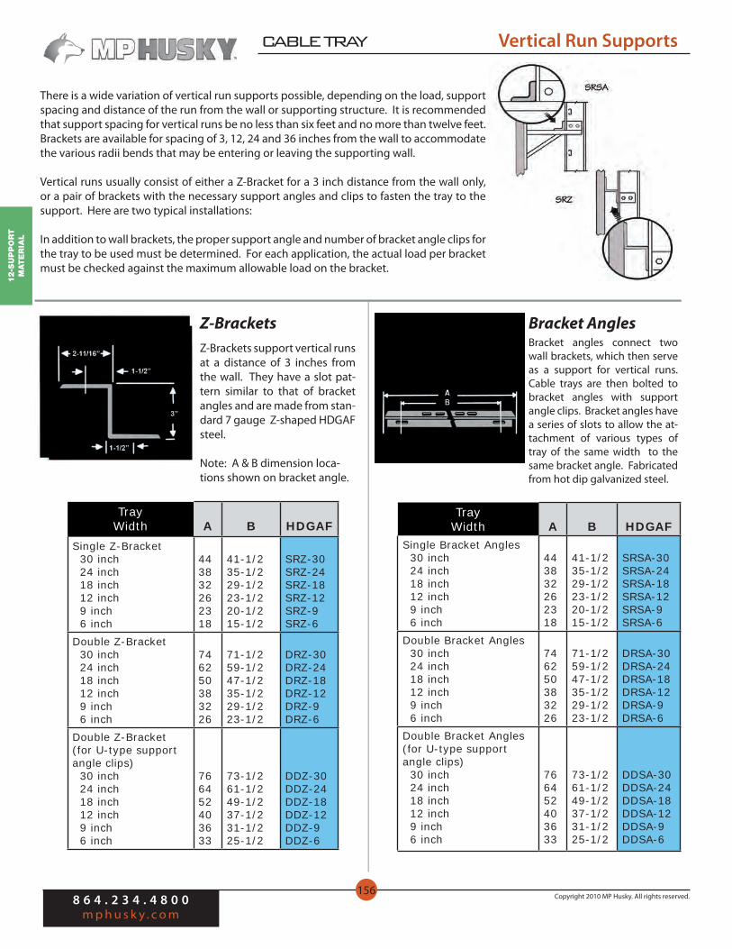
There is a wide variation of vertical run supports possible, depending on the load, support spacing and distance of the run from the wall or supporting structure. It is recommended that support spacing for vertical runs be no less than six feet and no more than twelve feet. Brackets are available for spacing of 3, 12, 24 and 36 inches from the wall to accommodate the various radii bends that may be entering or leaving the supporting wall.
Vertical runs usually consist of either a Z-Bracket for a 3 inch distance from the wall only, or a pair of brackets with the necessary support angles and clips to fasten the tray to the support. Here are two typical installations:
In addition to wall brackets, the proper support angle and number of bracket angle clips for the tray to be used must be determined. For each application, the actual load per bracket must be checked against the maximum allowable load on the bracket.
Bracket AnglesZ-BracketsBracket angles connect two wall brackets, which then serve as a support for vertical runs. Cable trays are then bolted to bracket angles with support angle clips. Bracket angles have a series of slots to allow the at-tachment of various types of tray of the same width to the same bracket angle. Fabricated from hot dip galvanized steel.
Z-Brackets support vertical runs at a distance of 3 inches from the wall. They have a slot pat-tern similar to that of bracket angles and are made from stan-dard 7 gauge Z-shaped HDGAF steel.
Note: A & B dimension loca-tions shown on bracket angle.
TrayWidth A B HDGAF
Single Bracket Angles 30 inch 24 inch 18 inch 12 inch 9 inch 6 inch
443832262318
41-1/235-1/229-1/223-1/220-1/215-1/2
SRSA-30SRSA-24SRSA-18SRSA-12SRSA-9SRSA-6
Double Bracket Angles 30 inch 24 inch 18 inch 12 inch 9 inch 6 inch
746250383226
71-1/259-1/247-1/235-1/229-1/223-1/2
DRSA-30DRSA-24DRSA-18DRSA-12DRSA-9DRSA-6
Double Bracket Angles(for U-type support angle clips) 30 inch 24 inch 18 inch 12 inch 9 inch 6 inch
766452403633
73-1/261-1/249-1/237-1/231-1/225-1/2
DDSA-30DDSA-24DDSA-18DDSA-12DDSA-9DDSA-6
TrayWidth A B HDGAF
Single Z-Bracket 30 inch 24 inch 18 inch 12 inch 9 inch 6 inch
443832262318
41-1/235-1/229-1/223-1/220-1/215-1/2
SRZ-30SRZ-24SRZ-18SRZ-12SRZ-9SRZ-6
Double Z-Bracket 30 inch 24 inch 18 inch 12 inch 9 inch 6 inch
746250383226
71-1/259-1/247-1/235-1/229-1/223-1/2
DRZ-30DRZ-24DRZ-18DRZ-12DRZ-9DRZ-6
Double Z-Bracket (for U-type support angle clips) 30 inch 24 inch 18 inch 12 inch 9 inch 6 inch
766452403633
73-1/261-1/249-1/237-1/231-1/225-1/2
DDZ-30DDZ-24DDZ-18DDZ-12DDZ-9DDZ-6
12-Su
pp
or
t M
ater
ial
CABLE TRAY
8 6 4 . 2 3 4 . 4 8 0 0m p h u s k y . c o m
Copyright 2010 MP Husky. All rights reserved.157
Supports
Support Angle Clips
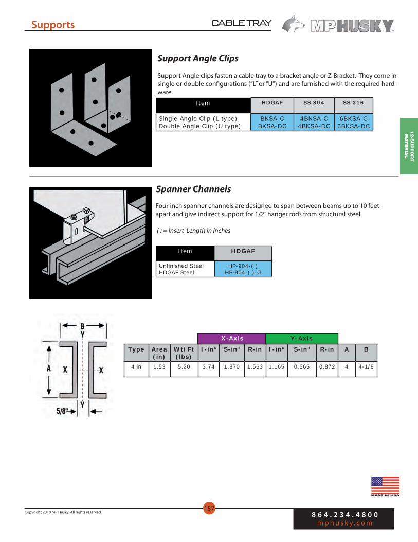
Support Angle clips fasten a cable tray to a bracket angle or Z-Bracket. They come in single or double configurations (“L” or “U”) and are furnished with the required hard-ware.
Item HDGAF SS 304 SS 316
Single Angle Clip (L type)Double Angle Clip (U type)
BKSA-CBKSA-DC
4BKSA-C4BKSA-DC
6BKSA-C6BKSA-DC
Spanner Channels
Four inch spanner channels are designed to span between beams up to 10 feet apart and give indirect support for 1/2” hanger rods from structural steel.
( ) = Insert Length in Inches
Item HDGAF
Unfinished SteelHDGAF Steel
HP-904-( )HP-904-( )-G
Type Area(in)
Wt/Ft(lbs)
I-in4 S-in3 R-in I-in4 S-in3 R-in A B
4 in 1.53 5.20 3.74 1.870 1.563 1.165 0.565 0.872 4 4-1/8
X-Axis Y-Axis

12-S
up
po
rt
Mat
er
ial
8 6 4 . 2 3 4 . 4 8 0 0m p h u s k y . c o m
Copyright 2010 MP Husky. All rights reserved.
CABLE TRAY
158
Wall Brackets
MP Husky offers a variety of wall brackets to support trays and channels from any wall or vertical support. The design of the brackets takes into consideration whether the trays or channels will be supported singly or two in parallel, on horizontal or vertical runs, the distance from the wall, bend radii, etc.
The allowable load of each type of bracket is given below: Condition 1—Where the load is applied at two points (ladders or troughs apart in width). Condition 2—Where the load is applied as a single concentrated load at the end of the bracket (as when supporting vertical runs).
A minimum safety factor of 2 against yield has been used in determining the maximum allowable load. All calculations have been confirmed by testing. Brackets are most commonly used for single or double horizontal runs.
Channel Brackets
Channel brackets will accommodate single or double channel runs with pre-drilled holes for HB-10 Hold Down Bolts or SGB-GU expansion guides, purchased separately.
Maximum allowable load:Twice the allowable load for the respective channel at a support spacing of 10 feet.
Item HDGAF SS 304 SS 316
Single for 4” ChannelDouble for 4” ChannelSingle for 6” ChannelDouble for 6” Channel
SSBK-GSDBK-GSSBK-G6SDBK-G6
4SSBK-G4SDBK-G4SSBK-G64SDBK-G6
6SSBK-G6SDBK-G6SSBK-G66SDBK-G6
Low Headroom BracketsLow headroom brackets are designed to attach Husky Trough and Husky Flange In Ladder to wall mounted strut type channel framing. Available in HDGAF.
Maximum allowable load:Condition 1—500 lbs.Condition 2—250 lbs.
A B C HDGAF
251913107
2115963
11-3/42-1/2
2-13/163-3/16
VBK-24VBK-18VBK-12VBK-9VBK-6
Condition 1
Condition 2

12-Su
pp
or
t M
ater
ial
CABLE TRAY
8 6 4 . 2 3 4 . 4 8 0 0m p h u s k y . c o m
Copyright 2010 MP Husky. All rights reserved.159
Wall Brackets
Medium Weight BracketsMedium weight brackets are used primarily to support 2 ladders side by side or 2 ladders one over the other. They are made of 3/16” structural angle, welded and hot dip galva-nized. The horizontal support angle is continuously slotted to increase the versatility of the bracket.
Maximum allowable load:Condition 1: 1200 lbs.Condition 2: 600 lbs.
Heavy Weight Brackets
Heavy weight, channel type brackets are used to support long spans or multiple ladder or trough installations that exceed the load capacity of ordinary brackets. They are welded from 3” structural steel channel with 1-1/2” channel stiffening members and hot dip gal-vanized. To develop the full strength of the brackets, the 3, 1/2” diameter bolts for which the wall members are drilled must be used.
Maximum allowable load:4,000 lbs. when applied as 2 equally concentrated loads, spaced at least 2’-4” apart on brackets five feet wide and under; or at least 4’-6” apart on brackets over five feet wide. The capacity is greater when used for a uniformly distributed load.
One Piece Wall BracketOne piece, light duty brackets are made from 1/8” thick hot dip galvanized steel. Placing one bracket below another allows a minimum vertical spacing of cable trays of 8”.
Maximum allowable load:Condition 1—600 lbs.Condition 2—300 lbs.
A Catalog No.
27-1/423-1/419-1/415-1/412-1/49-1/4
WBK-28LWBK-24LWBK-20LWBK-16LWBK-12LWBK-10L
Type A B C Catalog No.
49”39”30”21”
49393121
31-1/2262118
25-1/2201512
WBK-49MWBK-39MWBK-30MWBK-21M
Type A B C Catalog No.
66”60”54”48”42”36”
666054484236
636351513939
565644443232
WBK-66CWBK-60CWBK-54CWBK-48CWBK-42CWBK-36C

12-S
up
po
rt
Mat
er
ial
8 6 4 . 2 3 4 . 4 8 0 0m p h u s k y . c o m
Copyright 2010 MP Husky. All rights reserved.
CABLE TRAY
160
Wall Brackets
Single Strut BracketsDesigned primarily for use with strut framing, these brackets will work well in other applications. The uniform loads shown represent a 2.5 safety factor. Furnished in HDGAF steel.
Allowable concentrated end load:One half the listed uniform load.
TrayWidth
UniformLoad
Flange InFlange Out
FlangeOut
24”18”12”9”6”
200lbs.500lbs.700lbs.700lbs.1000lbs.
HP-S250-30HP-S250-24HP-S250-15HP-S250-12HP-S250-9
HP-S250-30HP-S250-24HP-S250-18HP-S250-15HP-S250-12
Double Strut BracketsSimilar to single strut brackets, but for wider trays and heavier loads. The uniform load shown represent a 2.5 safety factor. Furnished in HDGAF steel.
Allowable concentrated end load:One half the listed uniform load.
TrayWidth
UniformLoad
Flange InFlange Out
FlangeOut
36”30”24”18”
400lbs.650lbs.800lbs.1000lbs.
HP-S251-42HP-S251-36HP-S251-30HP-S251-24
HP-S251-42HP-S251-36HP-S251-30HP-S251-24
Strut Type Support ChannelHP-type channels provide indirect support for hanger rods by spanning between avail-able structural support beams and channels. The channel is supplied in 10’ or 20’ lengths and can easily be field cut to the length needed for use as a trapeze-type support. Avail-able in single or double (back to back) configurations.
P = Pre-Galvanized ( )120=10’G = HDGAF ( )240=20’
Single Double
WidthDepthWeight/Foot
1-5/8”1-5/8”2 lbs.
1-5/8”3-1/4”4 lbs.
Black SteelMill Galvan.HDGAF
HP-200-( )HP-200-( )-PHP-200-( )-G
HP-201-( )HP-201-( )-PHP-201-( )-G
Strut Hardware
Item Plated Steel SS 304 SS 316
1/2” Spring Nut HP-10TG 4HP-10TG 6HP-10TG1/2” Square Blank Nut HP-10WS 4HP-10WS 6HP-10WS
1-1/2” Square Washer, 9/16” Hole W-10 W-10-4S W-10-6S1/2” x 1-1/2” Hex Head Cap Screw B-61 B-61-4S B-61-6S
1/2” Lock Washer W-9 W-9-4S W-9-6S1/2” x 13 Hex Nut N-12 N-12-4S N-12-6S1/2” Flat Washer W-12 W-12-4S W-12-6S