Superior Energizer - v2t9n5r9.stackpathcdn.com
20
Superior Energizer Manual D425
Transcript of Superior Energizer - v2t9n5r9.stackpathcdn.com
Superior Energizer
Manual D425

Manual D425 • Logan Superior Energizer • Page 1
Logan Oil Tools
SuPERIOR ENERgIZER SERVIcE kIT
Logan Superior Energizer Service kit • 17
J1069Volume Pump
When ordering, please specify:(1) Name and number of assembly or part
cOMPLETE ASSEMbLY Logan Part No. 26000-055Consists of: Bowen No. 145213
SEAL PROTECTOR RING Logan Part No. J1073INSTALLATION TOOL Bowen No. 625O-RING Logan Part No. J1074INSTALLATION TOOL Bowen No. 626FILL PLUG WRENCH — Logan Part No. J1075T30 TORX HEAD Bowen No. 359TFILL PLUG WRENCH — Logan Part No. J1077ALLEN HEAD Bowen No. 620A1/4" x 1" PIPE NIPPLE Logan Part No. J1078
Bowen No. 36953LINE FILTER Logan Part No. J1080
Bowen No. 565651/4" MALE COUPLER Logan Part No. J1085
Bowen No. 6561/4" FEMALE COUPLER Logan Part No. J1086
Bowen No. 6553/8" BOX x 1/4" GALVANIZED Logan Part No. J1373BOX COUPLER Bowen No. …1/8" BOX x 1/4" Logan Part No. J1374PIN HEX BUSHING Bowen No. …
1/4" 19 NPT PIN Logan Part No. J1376HOSE FITTING Bowen No. …6 FT. EXHAUST HOSE Logan Part No. J1072
Bowen No. 33435PUMP HOSE Logan Part No. …
Bowen No. 2581VOLUME PUMP Logan Part No. J1069
Bowen No. 2580METAL BOX Logan Part No. J1070
Bowen No. 1995 5/8" FILL PLUG ADAPTER Logan Part No. J1224-001
Bowen No. …7/16" 20 NF Logan Part No. J1046-001FILL PLUG ADAPTER Bowen No. …3/8" 24 NF Logan Part No. J1045-001FILL PLUG ADAPTER Bowen No. …O-RING Logan Part No. 568010-100
Bowen No. 568010O-RING — 70 DURO NITRILE Logan Part No. 568005-100
Bowen No. 568005
J1070Metal Box
Pump Hose
J10726 Ft. Exhaust Hose
NOTES

Page 2 • Logan Superior Energizer • Manual D425
Logan Super ior Energ izer • 1
Cont ent s
Logan Super ior Energ izerOverview................................................................................ 2Operation............................................................................... 2Use with Superior Hydraulic Fishing Jar................................ 2Rig Up.................................................................................... 2Jarring.................................................................................... 3Rig Maintenance.................................................................... 3Dressing Area Maintenance .................................................. 3Equipment Required.............................................................. 3Disassembly .......................................................................... 4Inspection of Parts................................................................. 4
Pressure Body ................................................................... 4Impact Surfaces................................................................. 4Splines ............................................................................... 4
Assembly ............................................................................... 5Preparation............................................................................ 5Testing ................................................................................... 5Filling and Testing.................................................................. 5Test Load Chart ..................................................................... 6Jar Tester............................................................................... 7Illustration of Metal Parts ....................................................... 8Illustration of Polypaks and Seals.......................................... 9Strength Data ...............................................................10 – 11 ChartA–Specifications
Chart B – Strength and Test DataChart C – Recommended Tightening Torques
Complete Assemblies and Parts Lists ......................... 12 – 15Service Kit ................................................................... 16 – 17
LEGAL NOTICEAll references to Bowen® part numbers in this literature are used to identify interchangeable tools and parts. Reference to such tools and parts does not imply that Logan Oil Tools is a licenseeorisinanywayaffiliatedwithNationalOilwellVarco.LoganOilToolsdoesnotsell,oroffertosell,NationalOilwellVarco(Bowen)products.
“Bowen”isaregisteredtrademarkofNationalOilwellVarco.
3rd Printing, August 2012. Rev. 2

Manual D425 • Logan Superior Energizer • Page 3
2 • Logan Super ior Energ izer
OVERVIEW
The Logan Superior Energizer is essen-tiallyafluidspringthatstoresenergywhenastrainispulledonthefishingstring. Its function is to increase the im-pactenergydeliveredtothestuckfishby the Logan Superior Hydraulic Fishing Jar and the collars used to supply the impact energy.
When the strain is removed by the free strokeofthefishingjar,thestoredener-gy is released, accelerating the collars upward until a blow of high impact is struck.Thehydraulicfluidcontainedinthetoolcushionsmuchofthejarringshock from the rebounding string after each stroke to protect tools and string from damage.
Variableloadiscontrolledbyapplyinga lighter or heavier pull on the working string. A light pull will create light impact and a heavy pull will create hard impact at the strike point.
The Logan Superior Energizer is run inconjunctionwithaLoganSuperiorHydraulic Fishing Jar of the same size.Each size of Logan Superior Energizer is designed to match a corresponding size of Logan Superior Hydraulic Fish-ing Jar.
OPERATION
The Logan Superior Energizer is installed in the string when maximum jarringimpactandimpulseareneeded,particularly in shallow, deviated, ordirectional holes. Running strings lack stretch at shallow depths. Acceleration andeffectivenessofthejarringas-sembly are diminished due to the small amount of available stretch. In deviated or directional holes, friction between the running string and the wall of the hole will often diminish accelerated movement. In these cases, much ofthe energy will be lost. The Logan
Superior Energizer provides a means to store the required energy immediately abovethedrillcollarsandfishingjartooffset the loss of stretch or drag on the runningstring.Inconventionaljarringoperations, using either hydraulic or mechanicaljars,theintensityofablowis a function of, and is proportional to the accelerated movement of the entire runningstringabovethefishingjar.
Avoid running the tools at a highly devi- ated point or in the curve of a direction-al hole. Isolate the Logan Superior Hy-draulic Fishing Jar and Logan Superior Energizer from stiffer sections of the stringwithflexiblejoints.
The Logan Superior Energizer is simple to use and requires only a straight pull ataloaddeterminedbythejob.Itiscompletely safe to assemble since no high-pressure pre-loading is required.
All internal and external threaded con-nections are tightened to the recom-mended torque at the Logan manufac-turing facilities prior to shipment. Check all external connections after use to ensure proper torque is maintained.
CAUTION: Tong the Superior Ener-gizer approximately four inches from the threads. Do not tong directly over the threads. Doing so will damage the tool.
USE WITH THE LOGAN SUPERIOR HYDRAULIC FISHING J AR
The Logan Superior Energizer is always used with a Logan Superior Hydraulic Fishing Jar.
It is recommended that no less than twojointsofdrillcollarsornolessthanfourjointsofheavyweightdrillpipebeinstalled between the Logan Superior Hydraulic Fishing Jar and the Logan Superior Energizer.
RIG UP
Fill the Logan Superior Energizer with the correct Logan Energizer Fluid (seepage 13) and test the tool in a Logan Jar Tester (see page 7) or equivalent testfixturetoverifyperformance.
Before using, carefully examine the Logan Superior Energizer to be sure the tool has been properly assembled and filled,andthatthereisnoleakage.
Toachievemaximumeffectfromjarringaction, the Logan Superior Energizer should be installed in the string imme- diately above the drill collars, heavy-weight drill pipe, and other concentrated mass located between the Logan Supe-rior Hydraulic Fishing Jar and Energizer. Exceptwhenflexibilityisrequiredforbending, there should be no change in weightperfootinthefirst1,000feetin the working string directly above the Logan Superior Energizer.
NOTE: The Logan Superior Energizer is shipped from the factory in the closed position. The Superior Energizer is in-stalled between the running string (tub-ing or drill pipe) and the jarring mass (i.e. drill collars) that are located directly above the Logan Superior Hydraulic Fishing Jar. When the tool is elevated, the mandrel will stroke open two to three inches before elevating the at-tached fishing assembly. This is part of the temperature compensating design feature that makes the Logan Superior Energizer unique.
Once the tool is lowered into the well, downhole temperature will expand the energizer fluid and close this gap, in-creasing the working stroke of the tool.

Page 4 • Logan Superior Energizer • Manual D425
Logan Super ior Energ izer • 3
When the fishing string is pulled from the well, the Logan Superior Energizer will once again stroke open two to three inches.
This gap may be somewhat greater if a heavy length of fish is being recov-ered.
WARNING: The Logan Superior Fishing Jar is shipped from the fac-tory in the closed (cocked) position. The closed Superior Fishing Jar should not be left suspended in the elevator, especially with any signif-icant amount of weight suspended below it, as the tool may open and drop the length of its stroke, caus-ing damage or injury.
J ARRING
Velocityandrelativeimpactloadofa blow is controlled by the amount of stretchintherunningstring(pullload)and weight of the drill collars installed above the Logan Superior Hydraulic Fishing Jar. It is necessary to install similar weight above the Logan Supe-rior Energizer for a minimum of 1,000 feet to lessen the reverse inertia on thefishingjar.Applytheminimumpullload above the weight of the drill collars and string to obtain an effective blow.
CAUTION: Maximum pull load on the fishing jar should not be exceed-ed at any time during the pull cycle.
1. To strike the initial blow, set the stringdowntoensurethefishing jarisclosed.Raisethestringby
applying the desired pull load on thefishingjar.
2.Setthebrakeandwaitforthejartostrike. Depending on depth of oper-ation, amount of stretch on the string
(pullload),downholetemperature,hole condition, and other variables, the initial blow may take from a few seconds to several minutes.
3.Closethejarandrepeat.Itisonly necessarytoclosethejarbefore
stretching the string to strike the next blow. Any desired pull load, up
tothemaximumpullloadforthejar,may be struck on subsequent blows.
The Logan Superior Energizer can transmit full torque in either direction at all times while maintaining full circula-tion throughout the tool.
RIG MAINTENANCE
Nospecificactionisrequiredforrigdown. In most cases, after moderate useonashortjob,minormaintenancemaybeperformedontherigfloor.Afterinspectingtherigfloorforoilleaks,laythe Logan superior Energizer on the derrickfloor.
It is recommended that the Logan Superior Energizer should not remain suspended in the elevator for extended periods.
NOTE: The Logan Superior Energizer is shipped from the factory in the closed position. The Superior Energizer is in-stalled between the running string (tub-ing or drill pipe) and the jarring mass (i.e. drill collars) that are located directly above the Logan Superior Hydraulic Fishing Jar. When the tool is elevated, the mandrel will stroke open two to three inches before elevating the at-tached fishing assembly. This is part of the temperature compensating design feature that makes the Logan Supe-rior Energizer unique.
Once the tool is lowered into the well, downhole temperature will expand the energizer fluid and close this gap, in-creasing the working stroke of the tool. When the fishing string is pulled from the well, the Logan Superior Energizer will once again stroke open two to three inches.
This gap may be somewhat greater if a heavy length of fish is being recov-ered.
WARNING: The Logan Superior Fishing Jar is shipped from the fac- tory in the closed (cocked) position. The closed Superior Fishing Jar should not be left suspended in the elevator, especially with any signif-icant amount of weight suspended below it, as the tool may open and drop the length of its stroke, caus-ing damage or injury.
Immediately remove the Logan Superior Energizerfromthefishingstringandflushallmudfromthebore,especiallyfrom inside the washpipe.
DRESSING AREAMAINTENANCE
AfterprolongedfieldservicetheLoganSuperior Energizer should be disassem-bled, cleaned, inspected, and redressed.
EQUIPMENT REQUIRED
The following is a list of equipment that will be required to dress the Logan Superior Energizer.
1. A suitable vise and tong or equiv-alent device of suitable size.
2. Overhead crane with 2,000 lb.minimum capacity.
3. Pipe wrenches of suitable sizes for outside diameters of body parts and for all internal parts.
4. Chain wrenches of suitable sizes for all threaded parts.
5. A suitable belt pulley assembly that can be suspended from a hoist for rotating threaded parts during make up or break out.
6. Suitable nylon lift straps for lifting heavy parts during disassembly or assembly.
Manual D425 • Logan Superior Energizer • Page 5
4 • Logan Super ior Energ izer
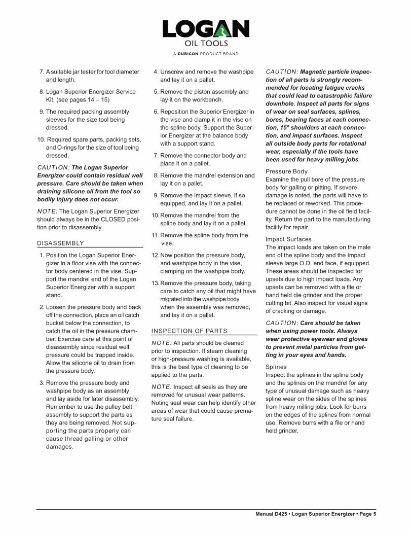
7.Asuitablejartesterfortooldiameterand length.
8. Logan Superior Energizer Service Kit. (see pages 14 – 15)
9. The required packing assembly sleeves for the size tool being dressed.
10. Required spare parts, packing sets, and O-rings for the size of tool being dressed.
CAUTION: The Logan Superior Energizer could contain residual well pressure. Care should be taken when draining silicone oil from the tool so bodily injury does not occur.
NOTE: The Logan Superior Energizer should always be in the CLOSED posi-tion prior to disassembly.
DISASSEMBLY
1. Position the Logan Superior Ener- gizerinafloorvisewiththeconnec-
tor body centered in the vise. Sup-port the mandrel end of the Logan Superior Energizer with a support stand.
2. Loosen the pressure body and back off the connection, place an oil catch bucket below the connection, to catch the oil in the pressure cham-ber. Exercise care at this point of disassembly since residual well pressure could be trapped inside. Allow the silicone oil to drain from the pressure body.
3. Remove the pressure body and washpipe body as an assembly and lay aside for later disassembly.Remember to use the pulley belt assembly to support the parts as they are being removed. Not sup-porting the parts properly can cause thread galling or other damages.
4. Unscrew and remove the washpipe and lay it on a pallet.
5. Remove the piston assembly and lay it on the workbench.
6. Reposition the Superior Energizer in the vise and clamp it in the vise on the spline body. Support the Super-ior Energizer at the balance body with a support stand.
7. Remove the connector body andplace it on a pallet.
8. Remove the mandrel extension and lay it on a pallet.
9. Remove the impact sleeve, if soequipped, and lay it on a pallet.
10.Remove the mandrel from the spline body and lay it on a pallet.
11. Remove the spline body from the vise.
12.Nowpositionthepressurebody,and washpipe body in the vise, clamping on the washpipe body.
13.Remove the pressure body, taking care to catch any oil that might have migrated into the washpipe bodywhen the assembly was removed, and lay it on a pallet.
INSPECTION OF PARTS
NOTE: All parts should be cleaned prior to inspection. If steam cleaning or high-pressure washing is available, this is the best type of cleaning to be applied to the parts.
NOTE: Inspect all seals as they are removed for unusual wear patterns. Noting seal wear can help identify other areas of wear that could cause prema-ture seal failure.
CAUTION: Magnetic particle inspec-tion of all parts is strongly recom-mended for locating fatigue cracks that could lead to catastrophic failure downhole. Inspect all parts for signs of wear on seal surfaces, splines, bores, bearing faces at each connec-tion, 15° shoulders at each connec-tion, and impact surfaces. Inspect all outside body parts for rotational wear, especially if the tools have been used for heavy milling jobs.
Pressure BodyExamine the pull bore of the pressure body for galling or pitting. If severe damage is noted, the parts will have to be replaced or reworked. This proce-durecannotbedoneintheoilfieldfacil-ity. Return the part to the manufacturing facility for repair.
Impact SurfacesThe impact loads are taken on the male end of the spline body and the Impact sleeve large O.D. end face, if equipped. These areas should be inspected for upsets due to high impact loads. Any upsetscanberemovedwithafileorhand held die grinder and the proper cutting bit. Also inspect for visual signs of cracking or damage.
CAUTION: Care should be taken when using power tools. Always wear protective eyewear and gloves to prevent metal particles from get-ting in your eyes and hands.
SplinesInspect the splines in the spline body and the splines on the mandrel for any type of unusual damage such as heavy spline wear on the sides of the splines fromheavymillingjobs.Lookforburrson the edges of the splines from normal use.Removeburrswithafileorhandheld grinder.
Page 6 • Logan Superior Energizer • Manual D425
Logan Super ior Energ izer • 5
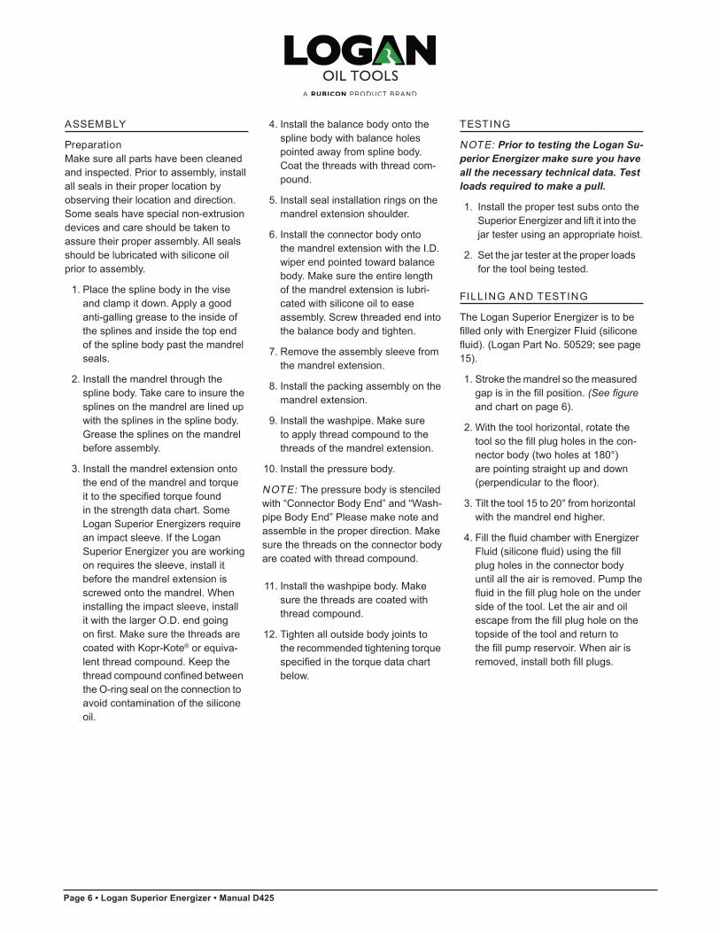
ASSEMBLY
PreparationMake sure all parts have been cleaned and inspected. Prior to assembly, install all seals in their proper location by observing their location and direction. Some seals have special non-extrusion devices and care should be taken to assure their proper assembly. All seals should be lubricated with silicone oil prior to assembly.
1. Place the spline body in the vise and clamp it down. Apply a good anti-galling grease to the inside of the splines and inside the top end of the spline body past the mandrel seals.
2. Install the mandrel through the spline body. Take care to insure the splines on the mandrel are lined up with the splines in the spline body.Grease the splines on the mandrel before assembly.
3. Install the mandrel extension ontothe end of the mandrel and torque
ittothespecifiedtorquefoundin the strength data chart. Some Logan Superior Energizers require an impact sleeve. If the Logan Superior Energizer you are working on requires the sleeve, install it before the mandrel extension is screwed onto the mandrel. When installing the impact sleeve, install it with the larger O.D. end going
onfirst.Makesurethethreadsarecoated with Kopr-Kote® or equiva-lent thread compound. Keep the
threadcompoundconfinedbetweenthe O-ring seal on the connection to avoid contamination of the silicone oil.
4. Install the balance body onto the spline body with balance holes pointed away from spline body.Coat the threads with thread com-pound.
5. Install seal installation rings on themandrel extension shoulder.
6. Install the connector body ontothe mandrel extension with the I.D. wiper end pointed toward balance body. Make sure the entire length of the mandrel extension is lubri-cated with silicone oil to ease assembly. Screw threaded end into the balance body and tighten.
7. Remove the assembly sleeve from the mandrel extension.
8. Install the packing assembly on the mandrel extension.
9. Install the washpipe. Make sureto apply thread compound to the threads of the mandrel extension.
10. Install the pressure body.
NOTE: The pressure body is stenciled with “Connector Body End” and “Wash-pipe Body End” Please make note and assemble in the proper direction. Make sure the threads on the connector body are coated with thread compound.
11. Install the washpipe body. Make sure the threads are coated with thread compound.
12.Tightenalloutsidebodyjointstothe recommended tightening torque
specifiedinthetorquedatachartbelow.
TESTING
NOTE: Prior to testing the Logan Su-perior Energizer make sure you haveall the necessary technical data. Test loads required to make a pull.
1. Install the proper test subs onto the Superior Energizer and lift it into the
jartesterusinganappropriatehoist.
2.Setthejartesterattheproperloadsfor the tool being tested.
FILLING AND TESTING
The Logan Superior Energizer is to be filledonlywithEnergizerFluid(siliconefluid).(Logan Part No. 50529; see page 15).
1. Stroke the mandrel so the measured gapisinthefillposition.(See figure
and chart on page 6).
2. With the tool horizontal, rotate the toolsothefillplugholesinthecon- nectorbody(twoholesat180°)
are pointing straight up and down (perpendiculartothefloor).
3.Tiltthetool15to20°fromhorizontalwith the mandrel end higher.
4.FillthefluidchamberwithEnergizer Fluid(siliconefluid)usingthefill
plug holes in the connector body until all the air is removed. Pump the
fluidinthefillplugholeontheunderside of the tool. Let the air and oil
escapefromthefillplugholeonthetopside of the tool and return to
thefillpumpreservoir.Whenairis removed,installbothfillplugs.
Manual D425 • Logan Superior Energizer • Page 7
6 • Logan Super ior Energ izer
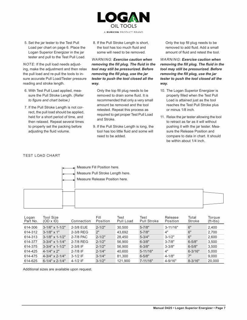
Measure Fill Position here.
Measure Pull Stroke Length here.
Measure Release Position here.
Additional sizes are available upon request.
Logan Tool Size Fill Test Test Release Total TorquePart No. (OD x ID) Connection Position Pull Load Pull Stroke Position Stroke (ft-lbs)
614-306 3-1/6" x 1-1/2" 2-3/8 EUE 2-1/2" 30,500 5-7/8" 3-11/16" 6" 2,400614-312 3-1/8" x 1" 2-3/8 REG 2" 43,692 5-7/8" 4" 6" 2,700614-313 3-1/8" x 1-1/2" 2-7/8 PAC 2-1/2" 28,450 5-3/4" 3-1/2" 6" 2,600614-377 3-3/4" x 1-1/4" 2-7/8 REG 2-1/2" 56,900 6-3/8" 3-7/8" 6-5/8" 3,500614-375 3-3/4" x 1-1/2" 2-3/8 IF 2-1/2" 56,900 6-3/8" 3-3/8" 6-5/8" 3,500614-425 4-1/4" x 2" 2-7/8 IF 2-1/4" 40,600 5-11/16" 4" 6-3/16" 5,000614-475 4-3/4" x 2-1/4" 3-1/2 IF 3-1/4" 81,300 6-5/8" 4-1/8" 7" 9,000614-625 6-1/4" x 2-1/4" 4-1/2 IF 3-1/2" 121,900 7-11/16" 4-9/16" 8-3/16" 20,000
5.SetthejartestertotheTestPullLoad per chart on page 6. Place the
LoganSuperiorEnergizerinthejartester and pull to the Test Pull Load.
NOTE: If the pull load needs adjust-ing, make the adjustment and then relax the pull load and re-pull the tools to in-sure accurate Pull Load/Tester pressure reading and stroke length.
6. With Test Pull Load applied, mea-sure the Pull Stroke Length. (Refer
to figure and chart below.)
7. If the Pull Stroke Length is not cor-rect, the pull load should be applied, held for a short period of time, and then relaxed. Repeat several times to properly set the packing before
adjustingthefluidvolume.
8. If the Pull Stroke Length is short, thetoolhastoomuchfluidand
some will need to be removed.
WARNING: Exercise caution when removing the fill plug. The fluid in the tool may still be pressurized. Before removing the fill plug, use the jar tester to push the tool closed all the way.
Onlythetopfillplugneedstobe removedtodrainsomefluid.Itis
recommended that only a very small amount be removed and the tool retested. Repeat this process as required to get proper Test Pull Load and Stroke.
9. If the Pull Stroke Length is long, the toolhastoolittlefluidandsomewill
need to be added.
Onlythetopfillplugneedstobe removedtoaddfluid.Addasmall amountoffluidandretestthetool.
WARNING: Exercise caution when removing the fill plug. The fluid in the tool may still be pressurized. Before removing the fill plug, use the jar tester to push the tool closed all the way.
10. The Logan Superior Energizer is properlyfilledwhentheTestPull Loadisattainedjustasthetool
reaches the Test Pull Stroke plus or minus 1/8 inch.
11.Relaxthejartesterallowingthetoolto retract as far as it will without
pushingitwiththejartester.Mea-sure the Release Position and compare to data in chart. It should be within about 1/4 inch.
TEST LOAD CHART
Page 8 • Logan Superior Energizer • Manual D425
Logan Super ior Energ izer • 7
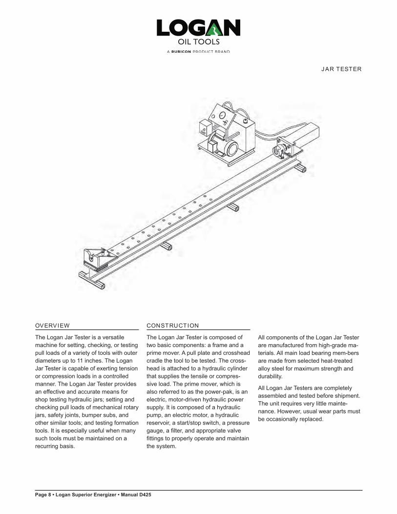
OVERVIEW
The Logan Jar Tester is a versatile machine for setting, checking, or testing pull loads of a variety of tools with outer diameters up to 11 inches. The Logan Jar Tester is capable of exerting tension or compression loads in a controlled manner. The Logan Jar Tester provides an effective and accurate means for shoptestinghydraulicjars;settingandchecking pull loads of mechanical rotary jars,safetyjoints,bumpersubs,andothersimilartools;andtestingformationtools. It is especially useful when many such tools must be maintained on a recurring basis.
CONSTRUCTION
The Logan Jar Tester is composed of two basic components: a frame and a prime mover. A pull plate and crosshead cradle the tool to be tested. The cross-head is attached to a hydraulic cylinder that supplies the tensile or compres-sive load. The prime mover, which is also referred to as the power-pak, is an electric, motor-driven hydraulic power supply. It is composed of a hydraulic pump, an electric motor, a hydraulic reservoir, a start/stop switch, a pressure gauge,afilter,andappropriatevalvefittingstoproperlyoperateandmaintainthe system.
All components of the Logan Jar Tester are manufactured from high-grade ma-terials. All main load bearing mem-bers are made from selected heat-treated alloy steel for maximum strength and durability.
All Logan Jar Testers are completely assembled and tested before shipment. The unit requires very little mainte-nance. However, usual wear parts must be occasionally replaced.
J AR TESTER

Manual D425 • Logan Superior Energizer • Page 9
8 • Logan Super ior Energ izer
Metal Parts(Upper Half)
Metal Parts(Lower Half)
Washpipe
MandrelImpact Sleeve
(not required for some assemblies)
Mandrel Extension
Mandrel
Connector Body
Spline Body
Piston Assembly
Washpipe Body
Pressure Body
Connector Body
Balance Body
Pressure Body Fill Plug2 Req’d
Pressure Body Fill Plug1 Req’d
Page 10 • Logan Superior Energizer • Manual D425
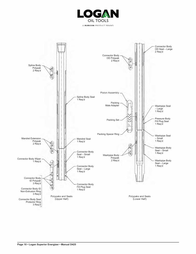
Polypaks and Seals(Upper Half)
Polypaks and Seals(Lower Half)
Washpipe Body Polypak2 Req’d
Mandrel Extension Polypak2 Req’d
Connector Body Wiper 1 Req’d
Connector BodySeal – Small 1 Req’d
Connector BodyFill Plug Seal 1 Req’d
Connector BodySeal – Large 1 Req’d
Mandrel Seal 1 Req’d
Packing Set
Washpipe Seal – Large1 Req’d
Washpipe Body Seal – Large1 Req’d
Connector Body OD Seal – Large2 Req’d
Washpipe Body Seal – Small 1 Req’d
Connector Body OD Polypak
2 Req’d
Packing Spacer Ring
Packing Male Adapter
Piston Assembly
Pressure Body Fill Plug Seal1 Req’d
Washpipe Seal – Small1 Req’d
Spline Body Seal 1 Req’d
Spline Body Polypak2 Req’d
Connector Body ID Polypak
3 Req’d
Connector Body ID Non-ExtrusionRing
3 Req’d
Connector Body Seal Protector Ring
3 Req’d
Logan Super ior Energ izer • 9
Manual D425 • Logan Superior Energizer • Page 11
10 • Logan Super ior Energ izer
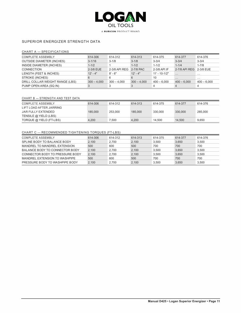
SUPERIOR ENERGIZER STRENGTH DATA
CHART A — SPECIFICATIONS
COMPLETE ASSEMBLY 614-306 614-312 614-313 614-375 614-377 614-376OUTSIDE DIAMETER (INCHES) 3-1/16 3-1/8 3-1/8 3-3/4 3-3/4 3-3/4INSIDE DIAMETER (INCHES) 1-1/2 1 1-1/2 1-1/2 1-1/4 1-7/8CONNECTION 2-3/8 EUE 2-3/8 API REG 2-7/8 PAC 2-3/8 API IF 2-7/8 API REG 2-3/8 EUELENGTH (FEET & INCHES) 12' - 4" 8' - 6" 12' - 4" 11' - 10-1/2" … …STROKE (INCHES) 6 6 6 10 … …DRILL COLLAR WEIGHT RANGE (LBS) 300 – 4,000 300 – 4,000 300 – 4,000 400 – 6,000 400 – 6,000 400 – 6,000PUMP OPEN AREA (SQ IN) 3 3 3 4 4 4
CHART B — STRENGTH AND TEST DATA
COMPLETE ASSEMBLY 614-306 614-312 614-313 614-375 614-377 614-376LIFT LOAD AFTER JARRINGJAR FULLY EXTENDED 185,000 253,000 185,000 330,000 330,000 285,000TENSILE @ YIELD (LBS)TORQUE @ YIELD (FT-LBS) 4,200 7,500 4,200 14,500 14,500 9,650
CHART C — RECOMMENDED TIGHTENING TORQUES (FT-LBS)
COMPLETE ASSEMBLY 614-306 614-312 614-313 614-375 614-377 614-376SPLINE BODY TO BALANCE BODY 2,100 2,700 2,100 3,500 3,650 3,500MANDREL TO MANDREL EXTENSION 500 600 500 700 700 700BALANCE BODY TO CONNECTOR BODY 2,100 2,700 2,100 3,500 3,650 3,500CONNECTOR BODY TO PRESSURE BODY 2,100 2,700 2,100 3,500 3,650 3,500MANDREL EXTENSION TO WASHPIPE 500 600 500 700 700 700PRESSURE BODY TO WASHPIPE BODY 2,100 2,700 2,100 3,500 3,650 3,500

Page 12 • Logan Superior Energizer • Manual D425
Logan Super ior Energ izer • 11
Mandrel
Balance Body Pressure BodySpline
ConnectorBody
WashpipeBody
Mandrel to Mandrel Extension
(internal connection)
Mandrel Extensionto Washpipe(internal connection)
CHART A — SPECIFICATIONS
COMPLETE ASSEMBLY 614-425 614-450 614-475 614-625 614-775OUTSIDE DIAMETER (INCHES) 4-1/4 4-1/2 4-3/4 6-1/4 7-3/4INSIDE DIAMETER (INCHES) 2 2-3/8 2-1/4 2-1/4 3-1/16CONNECTION 2-7/8 IF 2-7/8 EUE 3-1/2 IF 4-1/2 IF 6-5/8 REGLENGTH (FEET & INCHES) 11' - 4" … 11' - 6" 13' - 8" 15' - 7"STROKE (INCHES) 6-3/16 … 7 8-3/16 8-1/2DRILL COLLAR WEIGHT RANGE (LBS) 400 – 6,000 400 – 6,000 500 – 8000 8,500 – 15,000 12,200 – 21,000PUMP OPEN AREA (SQ IN) 6 7-1/2 7 11 16
CHART B — STRENGTH AND TEST DATA
COMPLETE ASSEMBLY 614-425 614-450 614-475 614-625 614-775LIFT LOAD AFTER JARRINGJAR FULLY EXTENDED 375,000 360,000 505,000 1,000,000 1,600,000TENSILE @ YIELD (LBS)TORQUE @ YIELD (FT-LBS) 18,500 12,000 18,100 40,800 79,000
CHART C — RECOMMENDED TIGHTENING TORQUES (FT-LBS)
COMPLETE ASSEMBLY 614-425 614-450 614-475 614-625 614-775SPLINE BODY TO BALANCE BODY 5,000 3,500 9,090 20,000 39,000MANDREL TO MANDREL EXTENSION 1,500 700 1,800 7,000 12,500BALANCE BODY TO CONNECTOR BODY 5,000 3,500 9,090 20,000 39,000CONNECTOR BODY TO PRESSURE BODY 5,000 3,500 9,090 20,000 39,000MANDREL EXTENSION TO WASHPIPE 1,500 700 1,000 4,800 10,500PRESSURE BODY TO WASHPIPE BODY 5,000 3,500 9,090 20,000 39,000
SUPERIOR ENERGIZER STRENGTH DATA

Manual D425 • Logan Superior Energizer • Page 13
12 • Logan Super ior Energ izer
SUPERIOR ENERGIZER
TOOL JOINT CONNECTION 2-3/8 EUE 2-3/8 2-7/8 PAC 2-3/8 2-7/8 2-3/8 2-7/8API REG API IF API REG EUE API IF
OUTSIDE DIAMETER — INCHES 3-1/16 3-1/8 3-1/8 3-3/4 3-3/4 3-3/4 4-1/4INSIDE DIAMETER — INCHES 1-1/2 1 1-1/2 1-1/2 1-1/4 1-7/8 2COMPLETE ASSEMBLY Logan Part No. 614-306 614-312 614-313 614-375 614-377 614-376 614-425
COMPONENTS
MANDREL Logan Part No. BX11 BX10 BX11 BX12 ** BX18 BX13MANDREL SEAL Logan Part No. 568-225 … 568-225 568-225 ** ** 568-229 No.Req’d. … … 1 1 … … 1SPLINE BODY Logan Part No. BX21 BX20 BX21 BX22 ** BX28 BX23SPLINE BODY SEAL Logan Part No. 568-230 568-230 568-230 568-234 ** ** 568-238 No.Req’d. 1 1 1 1 … … 1SPLINE BODY Logan Part No. BD205-1 BD205-1 BD205-1 BD202-3 ** ** BD202-2 POLYPAK No.Req’d. 2 2 2 2 … … 2MANDREL SLEEVE Logan Part No. BX31 BX30 BX31 … ** BX38 …BALANCE BODY Logan Part No. BX41 BX41 BX41 BX42 ** BX48 BX43MANDREL EXTENSION Logan Part No. BX51 BX50 BX51 BX52 ** BX58 BX53MANDREL EXTENSION Logan Part No. BD205-2 BD205-2 BD205-2 BD201-2 ** ** BX144-3 POLYPAK No.Req’d. 2 2 1 2 … … 2PISTON ASSEMBLY Logan Part No. BX61 BX60 BX61 BX62 ** BX68 BX63Consists of:PACKING SET Logan Part No. BX61-1 BX60-1 BX61-1 BX62-1 ** BX68-1 BX63-1PACKING Logan Part No. BX61-2 BX60-2 BX61-2 BX62-2 ** BX68-2 BX63-2MALE ADAPTERPACKING SPACER RING Logan Part No. BX61-3 BX60-3 BX61-3 BX62-3 ** BX68-3 BX63-3CONNECTOR BODY Logan Part No. BX71 BX70 BX71 BX72 ** BX78 BX73CONNECTOR BODY Logan Part No. … … … BD71 ** ** BD76 WIPERCONNECTOR BODY Logan Part No. BD205-3 BD200-3 BD205-3 BD201-3 ** ** AQ29005 ID POLYPAK No.Req’d. 3 3 3 3 … … 3CONNECTOR BODY ID Logan Part No. L365-32 L365-30 L365-32 BD231 ** ** BD236 NON-EXTRUSION RING No.Req’d. 2 2 2 3 … … 3CONNECTOR BODY Logan Part No. 8-228 … 8-228 ** ** ** **SEAL PROTECTOR RING No.Req’d. 2 … 2 … … … …CONNECTOR BODY Logan Part No. … … … … ** ** …OD PARBAK RING No.Req’d. … … … … … … …CONNECTOR BODY OD Logan Part No. L366-33.5 BX160 L366-33.5 … ** ** …NON-EXTRUSION RING No.Req’d. 2 1 2 … … … …CONNECTOR BODY Logan Part No. 568-228 568-330 568-228 568-232 ** ** 568-236 SEAL (SMALL) No.Req’d. 2 2 2 1 … … 1CONNECTOR BODY Logan Part No. 568-230 568-230 568-230 568-234 ** ** 568-238 SEAL (LARGE) No.Req’d. 2 2 2 2 … … 2CONNECTOR BODY Logan Part No. AG10000 AG10002 AG10000 AG10002 ** ** AG10002 FILL PLUG No.Req’d. 2 2 2 2 … … 2CONNECTOR BODY Logan Part No. 568-005 568-006 568-005 568-006 ** ** 568-006 FILL PLUG SEAL No.Req’d. 2 2 2 2 … … 2
* Redress Kits include O-Ring Packing Sets, Polypak Kits, and Connector Body Wipers** To be advised by engineering

Page 14 • Logan Superior Energizer • Manual D425
Logan Super ior Energ izer • 13
SUPERIOR ENERGIZER
TOOL JOINT CONNECTION 2-3/8 EUE 2-3/8 2-7/8 PAC 2-3/8 2-7/8 2-3/8 2-7/8API REG API IF API REG EUE API IF
OUTSIDE DIAMETER — INCHES 3-1/16 3-1/8 3-1/8 3-3/4 3-3/4 3-3/4 4-1/4INSIDE DIAMETER — INCHES 1-1/2 1 1-1/2 1-1/2 1-1/4 1-7/8 2COMPLETE ASSEMBLY Logan Part No. 614-306 614-312 614-313 614-375 614-377 614-376 614-425
COMPONENTS (CONTINUED)
CONNECTOR BODY Logan Part No. … … … AQ29003 ** ** AQ29005 OD POLYPAK No.Req’d. … … … 2 … … 2PRESSURE BODY Logan Part No. BX91 BX90 BX91 BX92 ** BX98 BX93PRESSURE BODY Logan Part No. AG10004 AG10004 AG10004 AG10004 ** ** AG10000 FILL PLUG No.Req’d. 1 1 1 1 … … 1PRESSURE BODY Logan Part No. … … … … ** ** 568-005 FILL PLUG SEAL No.Req’d. … … … … … … 1WASHPIPE Logan Part No. BX101 BX100 BX101 BX102 ** BX108 BX103WASHPIPE SEAL Logan Part No. … 568-130 … 568-227 ** ** 568-231 (LARGE) No.Req’d. … 1 … 1 … … 1WASHPIPE SEAL Logan Part No. 568-224 568-221 568-224 568-225 ** ** 568-229 (SMALL) No.Req’d. 1 1 1 1 … … 1WASHPIPE BODY Logan Part No. BX111 BX110 BX111 BX112 ** BX118 BX113WASHPIPE BODY SEAL Logan Part No. 568-230 568-230 568-230 568-234 ** ** 568-238 (LARGE) No.Req’d. 1 1 1 1 … … 1WASHPIPE BODY SEAL Logan Part No. 568-228 568-228 568-228 568-232 ** ** 568-236 (SMALL) No.Req’d. 1 1 1 1 … … 1WASHPIPE BODY Logan Part No. BD200-3 BD205-2 BD205-3 BD201-3 ** ** AQ29003 POLYPAK No.Req’d. 2 2 2 2 … … 2REDRESS KITS * Logan Part No. BX121 BX120 BX121 BX122 ** BX128 BX123O-RING PACKING SET Logan Part No. BX131 BX130 BX131 BX132 ** BX138 BX133POLYPAK KIT Logan Part No. BX141 BX140 BX141 BX142 ** BX148 BX143Consists of: SPLINE BODY Logan Part No. BD205-1 BD205-1 BD205-1 BD202-3 ** ** BD202-2 POLYPAK No.Req’d. 2 2 2 2 … … 2MANDREL EXTENSION Logan Part No. BD205-2 BD205-2 BD205-2 BD201-2 ** ** BX144-3 POLYPAK No.Req’d. 1 2 1 2 … … 2CONNECTOR BODY Logan Part No. BD205-3 BD200-3 BD205-3 BD201-3 ** ** AQ29005 ID POLYPAK No.Req’d. 3 3 3 3 … … 3CONNECTOR BODY Logan Part No. … … … AQ29003 ** ** AQ29005 OD POLYPAK No.Req’d. … … … 2 … … 2WASHPIPE BODY Logan Part No. BD205-3 BD205-2 BD205-3 BD201-3 ** ** AQ29003 POLYPAK No.Req’d. 2 2 2 2 … … 2MANDREL EXTENSION Logan Part No. BD205-6 BX140-5 BD205-6 BX201-6 ** ** BD206-6 ASSEMBLY SLEEVE No.Req’d. 1 … 1 1 … … 1
* Redress Kits include O-Ring Packing Sets, Polypak Kits, and Connector Body Wipers** To be advised by engineering

Manual D425 • Logan Superior Energizer • Page 15
14 • Logan Super ior Energ izer
SUPERIOR ENERGIZER
TOOL JOINT CONNECTION 3-1/2 4-1/2 5-1/2 6-5/8API IF API IF API REG API REG
OUTSIDE DIAMETER — INCHES 4-3/4 6-1/4 6-3/4 7-3/4 INSIDE DIAMETER — INCHES 2-1/4 2-1/4 2-3/4 3-1/16COMPLETE ASSEMBLY Logan Part No. 614-475 614-625 614-675 614-775
COMPONENTS
MANDREL Logan Part No. BX14 BX15 BX16 BX17MANDREL SEAL Logan Part No. 568-232 568-236 ** 568-348 No.Req’d. 1 1 … 1SPLINE BODY Logan Part No. BX24 BX25 BX26 BX27SPLINE BODY SEAL Logan Part No. 568-242 568-254 ** 568-362 No.Req’d. 1 1 … 1SPLINE BODY Logan Part No. BD202-1 BD203-1 ** BD204-1POLYPAK No.Req’d. 2 2 … 2 MANDREL SLEEVE Logan Part No. BX34 … BX36 BX37BALANCE BODY Logan Part No. BX44 BX45 BX46 BX47MANDREL EXTENSION Logan Part No. BX54 BX55 BX56 BX57MANDREL EXTENSION Logan Part No. BD202-2 BD203-2 ** BD204-2POLYPAK No.Req’d. 2 2 … 1MANDREL EXTENSION Logan Part No. … BD223 … BD224WIPERPISTON ASSEMBLY Logan Part No. BX64 BX65 BX66 BX67Consists of:PACKING SET Logan Part No. BX64-1 BX65-1 BX66-1 BX67-1PACKING Logan Part No. BX64-2 BX65-2 BX66-2 BX67-2 MALE ADAPTERPACKING SPACER RING Logan Part No. BX64-3 BX65-3 BX66-3 BX67-3CONNECTOR BODY Logan Part No. BX74 BX75 BX76 BX77CONNECTOR BODY Logan Part No. BX84 BD73 BX86 BD74 WIPERCONNECTOR BODY Logan Part No. BX144-3 BD203-3 ** BD204-3ID POLYPAK No.Req’d. 3 3 … …CONNECTOR BODY ID Logan Part No. BX154 BD233 ** BD234-001NON-EXTRUSION RING No.Req’d. 3 3 … … CONNECTOR BODY Logan Part No. L375-41 BD273 ** BD274SEAL PROTECTOR RING No.Req’d. 3 3 … …CONNECTOR BODY Logan Part No. … … ** BD204-2OD PARBAK RING No.Req’d. … … … …CONNECTOR BODY OD Logan Part No. ** … ** Not Req'd NON-EXTRUSION RING No.Req’d. … … … CONNECTOR BODY Logan Part No. 568-239 568-250 ** BD204-3SEAL (SMALL) No.Req’d. 1 1 … 1CONNECTOR BODY Logan Part No. 568-242 568-252 ** 568-362SEAL (LARGE) No.Req’d. 2 2 … 2CONNECTOR BODY Logan Part No. AG10002 AG10002 ** **FILL PLUG No.Req’d. 2 2 … …CONNECTOR BODY Logan Part No. 568-006 568-006 ** **FILL PLUG SEAL No.Req’d. 2 2 … …CONNECTOR BODY Logan Part No. BD202-5 BD203-5 ** **OD POLYPAK No.Req’d. 2 2 … …
* Redress Kits include O-Ring Packing Sets, Polypak Kits, and Connector Body Wipers** To be advised by engineering

Page 16 • Logan Superior Energizer • Manual D425
Logan Super ior Energ izer • 15
SUPERIOR ENERGIZER
TOOL JOINT CONNECTION 3-1/2 4-1/2 5-1/2 6-5/8API IF API IF API REG API REG
OUTSIDE DIAMETER — INCHES 4-3/4 6-1/4 6-3/4 7-3/4 INSIDE DIAMETER — INCHES 2-1/4 2-1/4 2-3/4 3-1/16COMPLETE ASSEMBLY Logan Part No. 614-475 614-625 614-675 614-775
COMPONENTS (CONTINUED)
CONNECTOR BODY Logan Part No. ** **OD POLYPAK No.Req’d. … … PRESSURE BODY Logan Part No. BX94 BX95 BX96 BX97PRESSURE BODY Logan Part No. AG10000 AG10000 ** **FILL PLUG No.Req’d. 1 1 … … PRESSURE BODY Logan Part No. 568-005 568-005 ** **FILL PLUG SEAL No.Req’d. 1 1 … …WASHPIPE Logan Part No. BX104 BX105 BX106 BX107WASHPIPE SEAL Logan Part No. 568-234 568-238 ** **(LARGE) No.Req’d. 1 1 … … WASHPIPE SEAL Logan Part No. 568-232 568-234 ** **(SMALL) No.Req’d. 1 1 … …WASHPIPE BODY Logan Part No. BX114 BX115 BX116 BX117WASHPIPE BODY SEAL Logan Part No. 568-242 568-252 ** **(LARGE) No.Req’d. 1 1 … …WASHPIPE BODY SEAL Logan Part No. 568-240 568-250** **(SMALL) No.Req’d. 1 1 … …WASHPIPE BODY Logan Part No. BX144-3 BD203-3 ** **POLYPAK No.Req’d. 2 2 … …REDRESS KITS * Logan Part No. BX124 BX125 BX126 BX127O-RING PACKING SET Logan Part No. BX134 BX135 BX136 BX137POLYPAK KIT Logan Part No. BX144 BX145 BX146 BX147Consists of: SPLINE BODY Logan Part No. BD202-1 BD203-1 ** **POLYPAK No.Req’d. 2 2 … …MANDREL EXTENSION Logan Part No. BD202-2 BD203-2 ** **POLYPAK No.Req’d. 2 2 … …CONNECTOR BODY Logan Part No. BX144-3 BD203-3 ** **ID POLYPAK No.Req’d. 3 3 … …CONNECTOR BODY Logan Part No. BD202-5 BD203-5 ** **OD POLYPAK No.Req’d. 2 2 … …WASHPIPE BODY Logan Part No. BX144-3 BD203-3 ** **POLYPAK No.Req’d. 2 2 … …MANDREL EXTENSION Logan Part No. BX144-5 BX145-5 ** **ASSEMBLY SLEEVE No.Req’d. 1 1 … …
ENERGIZER FLUID Logan Part No. 50529-A 50529-B 50529-C 50529-D 50529-E BowenNo. 50529-A 50529-B 50529-C 50529-D 50529
1 Gallon 2 Gallons 5 Gallons 30 Gallons 55 Gallons
* Redress Kits include O-Ring Packing Sets, Polypak Kits, and Connector Body Wipers** To be advised by engineering

Manual D425 • Logan Superior Energizer • Page 17
16 • Logan Super ior Energ izer Ser v ic e K i t
SUPERIOR ENERGIZER SERVICE K IT
J1045-0013/8" Fill Plug
Adapter
J10851/4" Male Couplers
J10861/4" Female Couplers
J1373Box Coupler
J1374Hex Bushing
J1376Hose Fitting
J1080Line Filter
568005-100O-Rings
568010-100O-Ring
J1073Installation Tool
J1074O-Ring Installation Tool
J1077Fill Plug Wrench
J1075Torx Head
Fill Plug Wrench
J1046-0017/16" Fill Plug
Adapter
J1224-0015/8" Fill Plug
Adapter
J10781/4"x1"PipeNipple
Note: Photos of parts are not actual size.

Page 18 • Logan Superior Energizer • Manual D425
COMPLETE ASSEMBLY Logan Part No. 26000-055
SEAL PROTECTOR RING INSTALLATION TOOL
Logan Part No. J1073
O-RING INSTALLATION TOOL Logan Part No. J1074
FILL PLUG WRENCH — T30 TORX HEAD
Logan Part No. J1075
FILL PLUG WRENCH — ALLEN HEAD
Logan Part No. J1077
1/4" x 1" PIPE NIPPLE Logan Part No. J1078
LINE FILTER Logan Part No. J1080
1/4" MALE COUPLER Logan Part No. J1085
1/4" FEMALE COUPLER Logan Part No. J1086
3/8" BOX x 1/4" GALVANIZED BOX COUPLER
Logan Part No. J1373
1/8" BOX x 1/4" PIN HEX BUSHING
Logan Part No. J1374
1/4" 19 NPT PIN HOSE FITTING
Logan Part No. J1376
6 FT. EXHAUST HOSE Logan Part No. J1072
PUMP HOSE Logan Part No. …
VOLUME PUMP Logan Part No. J1069
METAL BOX Logan Part No. J1070
5/8" FILL PLUG ADAPTER Logan Part No. J1224-001
7/16" 20 NF FILL PLUG ADAPTER
Logan Part No. J1046-001
3/8" 24 NF FILL PLUG ADAPTER
Logan Part No. J1045-001
O-RING Logan Part No. 568010-100
O-RING — 70 DURO NITRILE Logan Part No. 568005-100
When ordering, please specify:(1) Name and number of assembly or part
J1070Metal Box
J10726 Ft. Exhaust Hose
J1069Volume Pump
Pump Hose
SUPERIOR ENERGIZER SERVICE KIT

©2014 Logan Oil Tools12/2014
CORPORATE HEADQUARTERS
Logan International Inc. 7850 North Sam Houston Parkway West, Suite 100Houston, Texas 77064+1 832 386 2500
635 8th Avenue SouthwestSuite 850Calgary, Canada T2P 3M3 403 930 6810 | Fax 403 930 6811
U.S. SALES OFFICES
California 3155 Pegasus Drive Bakersfield, CA 93308-6800 661.387.1449 I Fax 661.387.1624
Louisiana 103 Bluffwood Drive Broussard , LA 70518-3310 337.839.2331 I Fax 337.839.2334
118 Common Court Houma, LA 70360-7982 985.868.7333 I Fax 985.868.7007
North Dakota 4925 Highway 85 South Williston , ND 58801 701.572.0565 I Fax 701.572.0644
Oklahoma 424 South Eagle Lane Oklahoma City, OK 73128-4225 405.782.0625 I Fax 405.782.0760
Pennsylvania 244 Grey Fox Drive, Suite 1 Montoursville , PA 17754-9572 570.546.1066 I Fax 570.546.0388
Texas 1519 South Flournoy Alice TX,78332 361.396.0139 I Fax 361.396.0112
11610 Cutten Road Houston, TX 77066-3008 832.602.2134 I Fax 832.286.4117
11006 Lucerne Street Houston, Texas 77016-1920 281.219.6613 I Fax 281.219.6638
1305 Energy Drive Kilgore, TX 75662-5539 903.984.6700 I Fax 903.984.6755
601 McDonald Odessa, TX 79761-6106 432.580.7414 I Fax 432.580.7656
Utah 1369 South 1100 East Vernal, UT 84078-8600 435.781.2856 I Fax 435.781.2858
INTERNATIONAL STOCKING DISTRIBUTORS
Canada Logan Oil Tools 9755 45th Avenue NW Edmonton , Alberta T6E 5V8 780.433.9957 I Fax 780.468.1979
Colombia Logan Oil Tools Sucursal Colombia Calle 113 No. 7-21 Edificio Teleport Business Park Torre A, Oficina 915 Bogota, Colombia (57.1 ).629.1995 I Fax (57.1 ).612.8357
A Singapore Logan Oil Tools Pte Ltd 54 Loyang Way Singapore 508747 65.65428422 I Fax 65.65420477
United Arab Emirates Logan Oil Tools Jebel Ali Free Zone (South) P.O. Box 23724 Dubai, UAE 971.4.813.8000 I Fax 971.4.813.8001
Woodhouse International P.O. Box 23724 Dubai, UAE 971.4.347.2300 I Fax 971.4.347.4642
United Kingdom Logan Oil Tools, U.K. Ltd. Unit C1 Kintore Business Park Kintore, lnverurie Aberdeenshire AB51 OYQ Scotland +44.1467.631190