Sun Fire V210 and V240 Servers Administration Guide
102
Sun Microsystems, Inc. 4150 Network Circle Santa Clara, CA 95054 U.S.A. 650-960-1300 Send comments about this document to: [email protected] Sun Fire V210 and V240 Servers Administration Guide Part No. 816-4826-11 April 2003, Revision A
Transcript of Sun Fire V210 and V240 Servers Administration Guide

Sun Microsystems, Inc.4150 Network CircleSanta Clara, CA 95054 U.S.A.650-960-1300
Send comments about this document to: [email protected]
Sun Fire V210 and V240 ServersAdministration Guide
Part No. 816-4826-11April 2003, Revision A

PleaseRecycle
Copyright 2002 Sun Microsystems, Inc., 4150 Network Circle, Santa Clara, CA 95054 U.S.A. All rights reserved.
This product or document is distributed under licenses restricting its use, copying, distribution, and decompilation. No part of this product ordocument may be reproduced in any form by any means without prior written authorization of Sun and its licensors, if any. Third-partysoftware, including font technology, is copyrighted and licensed from Sun suppliers.
Parts of the product may be derived from Berkeley BSD systems, licensed from the University of California. UNIX is a registered trademark inthe U.S. and other countries, exclusively licensed through X/Open Company, Ltd.
Sun, Sun Microsystems, the Sun logo, AnswerBook2, docs.sun.com, and Solaris are trademarks, registered trademarks, or service marks of SunMicrosystems, Inc. in the U.S. and other countries. All SPARC trademarks are used under license and are trademarks or registered trademarksof SPARC International, Inc. in the U.S. and other countries. Products bearing SPARC trademarks are based upon an architecture developed bySun Microsystems, Inc. The Energy Star logo is a registered trademark of EPA.
The OPEN LOOK and Sun™ Graphical User Interface was developed by Sun Microsystems, Inc. for its users and licensees. Sun acknowledgesthe pioneering efforts of Xerox in researching and developing the concept of visual or graphical user interfaces for the computer industry. Sunholds a non-exclusive license from Xerox to the Xerox Graphical User Interface, which license also covers Sun’s licensees who implement OPENLOOK GUIs and otherwise comply with Sun’s written license agreements.
Federal Acquisitions: Commercial Software—Government Users Subject to Standard License Terms and Conditions.
DOCUMENTATION IS PROVIDED “AS IS” AND ALL EXPRESS OR IMPLIED CONDITIONS, REPRESENTATIONS AND WARRANTIES,INCLUDING ANY IMPLIED WARRANTY OF MERCHANTABILITY, FITNESS FOR A PARTICULAR PURPOSE OR NON-INFRINGEMENT,ARE DISCLAIMED, EXCEPT TO THE EXTENT THAT SUCH DISCLAIMERS ARE HELD TO BE LEGALLY INVALID.
Copyright 2002 Sun Microsystems, Inc., 4150 Network Circle, Santa Clara, CA 95054 Etats-Unis. Tous droits réservés.
Ce produit ou document est distribué avec des licences qui en restreignent l’utilisation, la copie, la distribution, et la décompilation. Aucunepartie de ce produit ou document ne peut être reproduite sous aucune forme, par quelque moyen que ce soit, sans l’autorisation préalable etécrite de Sun et de ses bailleurs de licence, s’il y en a. Le logiciel détenu par des tiers, et qui comprend la technologie relative aux polices decaractères, est protégé par un copyright et licencié par des fournisseurs de Sun.
Des parties de ce produit pourront être dérivées des systèmes Berkeley BSD licenciés par l’Université de Californie. UNIX est une marquedéposée aux Etats-Unis et dans d’autres pays et licenciée exclusivement par X/Open Company, Ltd.
Sun, Sun Microsystems, le logo Sun, AnswerBook2, docs.sun.com, et Solaris sont des marques de fabrique ou des marques déposées, oumarques de service, de Sun Microsystems, Inc. aux Etats-Unis et dans d’autres pays. Toutes les marques SPARC sont utilisées sous licence etsont des marques de fabrique ou des marques déposées de SPARC International, Inc. aux Etats-Unis et dans d’autres pays. Les produits portantles marques SPARC sont basés sur une architecture développée par Sun Microsystems, Inc.
L’interface d’utilisation graphique OPEN LOOK et Sun™ a été développée par Sun Microsystems, Inc. pour ses utilisateurs et licenciés. Sunreconnaît les efforts de pionniers de Xerox pour la recherche et le développement du concept des interfaces d’utilisation visuelle ou graphiquepour l’industrie de l’informatique. Sun détient une licence non exclusive de Xerox sur l’interface d’utilisation graphique Xerox, cette licencecouvrant également les licenciés de Sun qui mettent en place l’interface d’utilisation graphique OPEN LOOK et qui en outre se conforment auxlicences écrites de Sun.
Achats fédéraux : logiciel commercial - Les utilisateurs gouvernementaux doivent respecter les conditions du contrat de licence standard.
LA DOCUMENTATION EST FOURNIE “EN L’ETAT” ET TOUTES AUTRES CONDITIONS, DECLARATIONS ET GARANTIES EXPRESSESOU TACITES SONT FORMELLEMENT EXCLUES, DANS LA MESURE AUTORISEE PAR LA LOI APPLICABLE, Y COMPRIS NOTAMMENTTOUTE GARANTIE IMPLICITE RELATIVE A LA QUALITE MARCHANDE, A L’APTITUDE A UNE UTILISATION PARTICULIERE OU AL’ABSENCE DE CONTREFAÇON.
Contents
1. Introduction 1
Overview of the Servers 2
Sun Fire V210 Server 2
Sun Fire V240 Server 3
Features 3
Differences Between The Servers 4
Bezel Features 4
Server Status Indicators 5
▼ To Turn The Locator LED On 6
▼ To Turn The Locator LED Off 6
Front Panel Features 7
On/Standby Switch 7
Hard disk drives 9
DVD-ROM Drive 9
System Configuration Card (SCC) 10
Keyswitch (Sun Fire V240 server only) 12
Back Panel Features 14
I/O Ports 15
Network Status Indicators 15
Contents iii
USB Ports 16
External SCSI Port 16
Power Supply Unit (PSU) 17
Optional Components 18
System Prompts 19
2. Removing and Replacing Components 21
Replaceable Components 22
Avoiding Electrostatic Discharge 22
▼ To Avoid Electrostatic Discharge While Working On The Front Panel 22
▼ To Open The Front Bezel 22
Controlling Server Power 24
▼ To Power On Using the On/Standby Switch 24
▼ To Power Off Using The On/Standby Switch 25
Swapping the System Configuration Card Between Servers 25
▼ To Swap the System Configuration Card Between Servers 25
Removing and Replacing Hard Disk Drives 27
Removing A Hard Disk Drive 27
Installing A Hard Disk Drive 28
Installing a SCSI Hard Disk Drive With Solaris Running 29
Removing a SCSI Hard Disk Drive With Solaris Running 30
Removing And Replacing The DVD-ROM Drive 32
▼ To Replace The DVD-ROM Drive 33
Sun Fire V240 Server: Removing and Replacing a Power Supply Unit 34
▼ To Remove a Power Supply Unit 34
▼ To Replace a Power Supply Unit 34
3. Sun™ Advanced Lights-Out Manager 37
Sun™ Advanced Lights-Out Manager 1.0 (ALOM) 38
Contents iv
ALOM Management Ports 39
Setting the admin Password 39
Basic ALOM Functions 40
▼ To Switch To The ALOM Prompt 40
▼ To Switch To The Server Console Prompt 40
4. Sun Management Center 41
Sun Management Center 42
How Sun Management Center Works 42
Other Sun Management Center Features 43
Using Sun Management Center 43
Hardware Diagnostic Suite 44
When to Run Hardware Diagnostic Suite 44
Requirements for Using Hardware Diagnostic Suite 44
5. Sun VTS 47
SunVTS 48
SunVTS Software and Security 48
Using SunVTS 49
▼ To Find Out Whether SunVTS Is Installed 50
Installing SunVTS 50
Viewing SunVTS Documentation 50
6. Diagnostics 53
Overview Of Diagnostic Tools 54
Sun™ Advanced Lights-Out Manager 55
Status Indicators 56
POST Diagnostics 56
▼ To Start POST Diagnostics 57
Controlling POST Diagnostics 58
Contents v
OpenBoot Diagnostics 59
▼ To Start OpenBoot Diagnostics 60
Controlling OpenBoot Diagnostics Tests 61
OpenBoot Commands 63
▼ To Run OpenBoot Commands 66
Operating Environment Diagnostic Tools 67
Error and System Message Log Files 67
Solaris System Information Commands 67
▼ To Run Solaris System Information Commands 75
Recent Diagnostic Test Results 76
▼ To View Recent Test Results 76
OpenBoot Configuration Variables 76
▼ To View And Set OpenBoot Configuration Variables 77
Additional Diagnostic Tests for Specific Devices 78
Using the probe-scsi Command To Confirm That Hard Disk Drives AreActive 78
Using the probe-ide Command To Confirm That the DVD or CD-ROMDrive is Connected 79
Using the watch-net and watch-net-all Commands To Check theNetwork Connections 79
Automatic Server Restart 80
Automatic System Recovery (ASR) 81
Auto-Boot Options 82
Error Handling Summary 82
Reset Scenarios 83
▼ To Enable ASR 83
▼ To Disable ASR 84
vi Sun Fire V210 and V240 Servers Administration Guide • April 2003

Figures
FIGURE 1-1 The Sun Fire V210 Server 2
FIGURE 1-2 The Sun Fire V240 Server 3
FIGURE 1-3 Location of Status Indicators (Sun Fire V210 Server Shown) 5
FIGURE 1-4 Location Of Front Panel Features 7
FIGURE 1-5 Location Of Hard Disk Drive Service Indicators (Sun Fire V120 Server Shown) 9
FIGURE 1-6 Location Of The Keyswitch (Sun Fire V240 Server Only) 13
FIGURE 1-7 Keyswitch Positions (Sun Fire V240 Server Only) 13
FIGURE 1-8 I/O Ports On A Sun Fire V210 Server 14
FIGURE 1-9 I/O Ports On A Sun Fire V240 Server 15
FIGURE 1-10 Location Of Network Status Indicators 15
FIGURE 1-11 System Prompt Flow Diagram 19
FIGURE 2-1 Opening The Bezel on a Sun Fire V210 Server 23
FIGURE 2-2 Opening The Bezel on a Sun Fire V210 Server 23
FIGURE 2-3 Inserting a System Configuration Card (Sun Fire V210 Server Shown) 26
FIGURE 2-4 Inserting a Hard Disk Drive (Sun Fire V210 Server Shown) 28
FIGURE 2-5 Removing a DVD-ROM Drive (Sun Fire V240 Shown) 33
FIGURE 6-1 probe-scsi Output Message 78
FIGURE 6-2 probe-scsi-all Output Message 78
FIGURE 6-3 probe-ide Output Message 79
FIGURE 6-4 watch-net Diagnostic Output Message 80
Figures vii

FIGURE 6-5 watch-net-all Diagnostic Output Message 80
Figures viii
Tables
TABLE 1-1 Sun Fire V210 and V240 Server: Differences 4
TABLE 1-2 Server Status Indicators 5
TABLE 1-3 On/Standby Switch Actions and Results 8
TABLE 1-4 Explanation of Power States 8
TABLE 1-5 Hard Disk Drive Service Indicators 9
TABLE 1-6 OBP Configuration Parameters Stored On The System Configuration Card 10
TABLE 1-7 Keyswitch Position and Server Behaviours 14
TABLE 1-8 Network Link Indicators 16
TABLE 1-9 Network Speed Indicators 16
TABLE 1-10 Power Supply Unit Indicators 17
TABLE 1-11 Power Supply Unit Ready To Remove Indicator (Sun Fire V240 only) 17
TABLE 1-12 Optional Components 18
TABLE 3-1 What ALOM Monitors 38
TABLE 4-1 What Sun Management Center Monitors 42
TABLE 5-1 SunVTS Tests 49
TABLE 6-1 Summary of Diagnostic Tools 54
TABLE 6-2 What ALOM Monitors 56
TABLE 6-3 OpenBoot Configuration Variables 58
TABLE 6-4 Sample obdiag Menu 60
TABLE 6-5 Keywords for the test-args OpenBoot Configuration Variable 61
Tables ix

TABLE 6-6 Using Solaris Information Display Commands 75
x Sun Fire V210 and V240 Servers Administration Guide • April 2003
Preface
The Sun Fire V210 and V240 Servers Administration Guide is intended to be used byexperienced system administrators. As well as general descriptive information aboutthe Sun Fire V210 and V240 servers, it includes detailed instructions on the variousserver administration tasks.
To use the information in this manual you must have a working knowledge ofcomputer network concepts and terms, and advanced knowledge of the Solaris™operating environment.
Before You Read This BookThis book does not cover server installation and rackmounting. For detailedinformation on those topics, refer to the Sun Fire V210 and V240 Servers InstallationGuide.
Before following any of the procedures described in this book, ensure you have readthe Sun Fire V210 and V240 Servers Compliance and Safety Manual.
Using UNIX CommandsThis document does not contain information on basic UNIX® commands andprocedures such as shutting down the system, booting the system, and configuringdevices.
See one or more of the following for this information:
xi

■ Solaris Handbook for Sun Peripherals■ Other software documentation that you received with your system
xii Sun Fire V210 and V240 Servers Administration Guide • April 2003
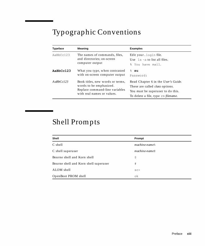
Typographic Conventions
Shell Prompts
Typeface Meaning Examples
AaBbCc123 The names of commands, files,and directories; on-screencomputer output
Edit your.login file.Use ls -a to list all files.% You have mail.
AaBbCc123 What you type, when contrastedwith on-screen computer output
% su
Password:
AaBbCc123 Book titles, new words or terms,words to be emphasized.Replace command-line variableswith real names or values.
Read Chapter 6 in the User’s Guide.These are called class options.You must be superuser to do this.To delete a file, type rm filename.
Shell Prompt
C shell machine-name%
C shell superuser machine-name#
Bourne shell and Korn shell $
Bourne shell and Korn shell superuser #
ALOM shell sc>
OpenBoot PROM shell ok
Preface xiii

Related Documentation
Read the Sun Fire V210 and V240 Servers Compliance and Safety Guide beforeperforming any of the procedures documented in this manual.
Accessing Sun Documentation OnlineYou can view, print, or purchase a broad selection of Sun documentation, includinglocalized versions, at:
http://www.sun.com/documentation
Sun Welcomes Your CommentsSun is interested in improving its documentation and welcomes your comments andsuggestions. You can email your comments to Sun at:
Please include the part number (816-4826-xx) of your document in the subject line ofyour email.
Application Title Part Number
Unpacking Sun Fire V210 and V240 Servers QuickStart Guide
816-4824-xx
Installation Sun Fire V210 and V240 ServersCompliance and Safety ManualSun Fire V210 and V240 ServersInstallation Guide
817-1462-xx
816-4825-xx
Lights-Out Management ALOM Online Help 817-0076-xx
Latest information Sun Fire V210 and V240 Server ProductNotes
816-4828-xx
xiv Sun Fire V210 and V240 Servers Administration Guide • April 2003
CHAPTER 1
Introduction
This chapter describes the Sun Fire V210 and V240 servers and gives an overview oftheir main features. It contains the sections:
■ “Overview of the Servers” on page 2
■ “Bezel Features” on page 4
■ “Back Panel Features” on page 14
■ “Optional Components” on page 18
■ “System Prompts” on page 19
1
Overview of the Servers
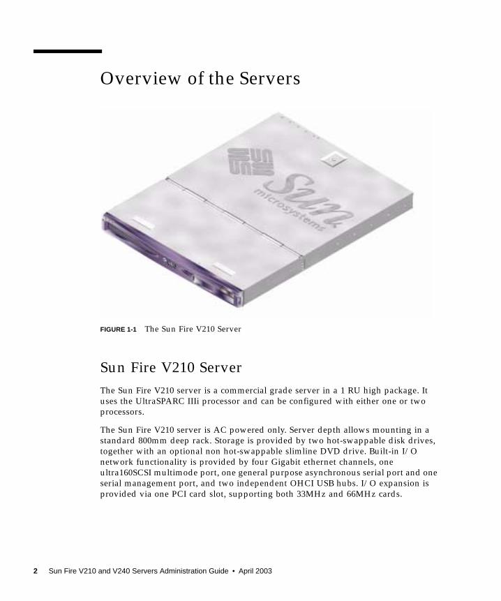
FIGURE 1-1 The Sun Fire V210 Server
Sun Fire V210 ServerThe Sun Fire V210 server is a commercial grade server in a 1 RU high package. Ituses the UltraSPARC IIIi processor and can be configured with either one or twoprocessors.
The Sun Fire V210 server is AC powered only. Server depth allows mounting in astandard 800mm deep rack. Storage is provided by two hot-swappable disk drives,together with an optional non hot-swappable slimline DVD drive. Built-in I/Onetwork functionality is provided by four Gigabit ethernet channels, oneultra160SCSI multimode port, one general purpose asynchronous serial port and oneserial management port, and two independent OHCI USB hubs. I/O expansion isprovided via one PCI card slot, supporting both 33MHz and 66MHz cards.
2 Sun Fire V210 and V240 Servers Administration Guide • April 2003
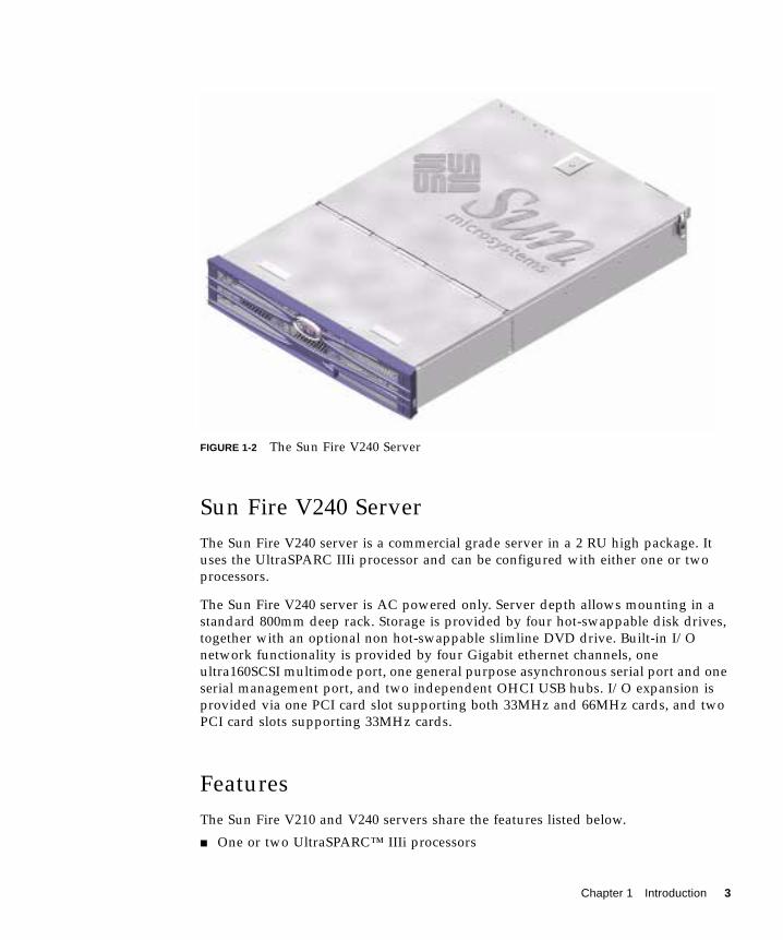
FIGURE 1-2 The Sun Fire V240 Server
Sun Fire V240 ServerThe Sun Fire V240 server is a commercial grade server in a 2 RU high package. Ituses the UltraSPARC IIIi processor and can be configured with either one or twoprocessors.
The Sun Fire V240 server is AC powered only. Server depth allows mounting in astandard 800mm deep rack. Storage is provided by four hot-swappable disk drives,together with an optional non hot-swappable slimline DVD drive. Built-in I/Onetwork functionality is provided by four Gigabit ethernet channels, oneultra160SCSI multimode port, one general purpose asynchronous serial port and oneserial management port, and two independent OHCI USB hubs. I/O expansion isprovided via one PCI card slot supporting both 33MHz and 66MHz cards, and twoPCI card slots supporting 33MHz cards.
FeaturesThe Sun Fire V210 and V240 servers share the features listed below.
■ One or two UltraSPARC™ IIIi processors
Chapter 1 Introduction 3
■ Four DIMM slots per processor■ Four 10/100/1000Base-T Ethernet ports■ One Ultra160 SCSI port for connecting external devices■ One general purpose serial port■ One serial management port■ Two USB ports■ One 10Base-T Ethernet server management port■ PCI expansion■ DVD-ROM drive■ Hot swappable hard disk drives■ System configuration card■ Front and rear service indicators
Differences Between The Servers
Bezel FeaturesThe front bezel of the Sun Fire V210 and V240 server contains the server status LEDsand a space for placing an identification label.
TABLE 1-1 Sun Fire V210 and V240 Server: Differences
Sun Fire V210 server Sun Fire V240 server
Height 1 RU high 2 RU high
PCI1x64-bit 33/66 MHz 3.3V PCIslot
1x64-bit 33/66 MHz 3.3V PCIslot2x64-bit 33 MHz 5V PCI slots
Hard disk drive bays Two Ultra160 SCSI Four Ultra160 SCSI
Power supply units Single AC Dual redundant AC
Keyswitch None Behind bezel
4 Sun Fire V210 and V240 Servers Administration Guide • April 2003
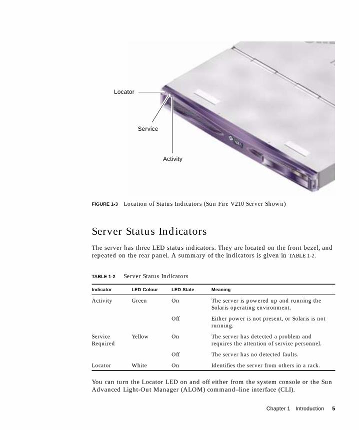
FIGURE 1-3 Location of Status Indicators (Sun Fire V210 Server Shown)
Server Status IndicatorsThe server has three LED status indicators. They are located on the front bezel, andrepeated on the rear panel. A summary of the indicators is given in TABLE 1-2.
You can turn the Locator LED on and off either from the system console or the SunAdvanced Light-Out Manager (ALOM) command–line interface (CLI).
TABLE 1-2 Server Status Indicators
Indicator LED Colour LED State Meaning
Activity Green On The server is powered up and running theSolaris operating environment.
Off Either power is not present, or Solaris is notrunning.
ServiceRequired
Yellow On The server has detected a problem andrequires the attention of service personnel.
Off The server has no detected faults.
Locator White On Identifies the server from others in a rack.
Locator
Service
Activity
Chapter 1 Introduction 5
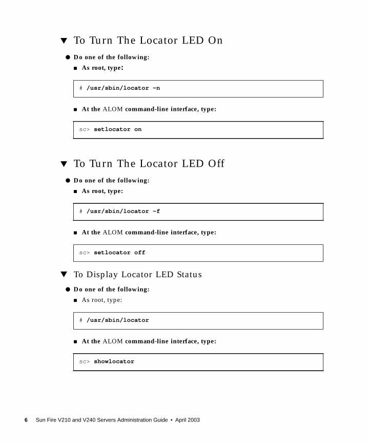
▼ To Turn The Locator LED On● Do one of the following:
■ As root, type:
■ At the ALOM command-line interface, type:
▼ To Turn The Locator LED Off● Do one of the following:
■ As root, type:
■ At the ALOM command-line interface, type:
▼ To Display Locator LED Status
● Do one of the following:
■ As root, type:
■ At the ALOM command-line interface, type:
# /usr/sbin/locator -n
sc> setlocator on
# /usr/sbin/locator -f
sc> setlocator off
# /usr/sbin/locator
sc> showlocator
6 Sun Fire V210 and V240 Servers Administration Guide • April 2003
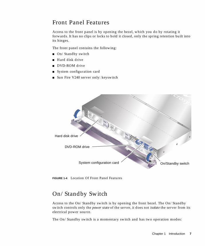
Front Panel FeaturesAccess to the front panel is by opening the bezel, which you do by rotating itforwards. It has no clips or locks to hold it closed, only the spring retention built intoits hinges.
The front panel contains the following:
■ On/Standby switch
■ Hard disk drive
■ DVD-ROM drive
■ System configuration card
■ Sun Fire V240 server only: keyswitch
FIGURE 1-4 Location Of Front Panel Features
On/Standby SwitchAccess to the On/Standby switch is by opening the front bezel. The On/Standbyswitch controls only the power state of the server, it does not isolate the server from itselectrical power source.
The On/Standby switch is a momentary switch and has two operation modes:
DVD-ROM drive
Hard disk drive
On/Standby switchSystem configuration card
Chapter 1 Introduction 7
■ Press and immediately release■ Press and hold down for more than 4 seconds
The results of these actions are summarised in TABLE 1-3.
Controlling Server Power
For information on connecting the server to a power source and powering on theserver, see the Sun Fire V210 and V240 Servers Installation Guide.
For information on controlling server power using software, see the ALOM OnlineHelp which is located on the Sun Fire V210 and V240 Servers Documentation CD.
The server immediately goes into Standby mode as soon as it is connected to apower source. As long as it remains connected to the power source, the server staysin either the Standby or On power state. An explanation of the power states is givenin TABLE 1-4.
Note – The only way to remove power totally from the server is to disconnect thepower cable.
TABLE 1-3 On/Standby Switch Actions and Results
Server Power State Press and release Press down for more than 4 seconds
On (with Solarisrunning)
Software performs orderlyshutdown. Server entersStandby state
Server enters Standby statedirectly
On (with Solaris notrunning)
No effect Server enters Standby statedirectly
Standby Server enters On power state Server enters On power state
TABLE 1-4 Explanation of Power States
Power State Description
On Server is connected to a power source and the power is enabled.
Standby Server is connected to a power source but power is not enabled.
Off Server is not connected to a power source. Power cable isdisconnected.
8 Sun Fire V210 and V240 Servers Administration Guide • April 2003
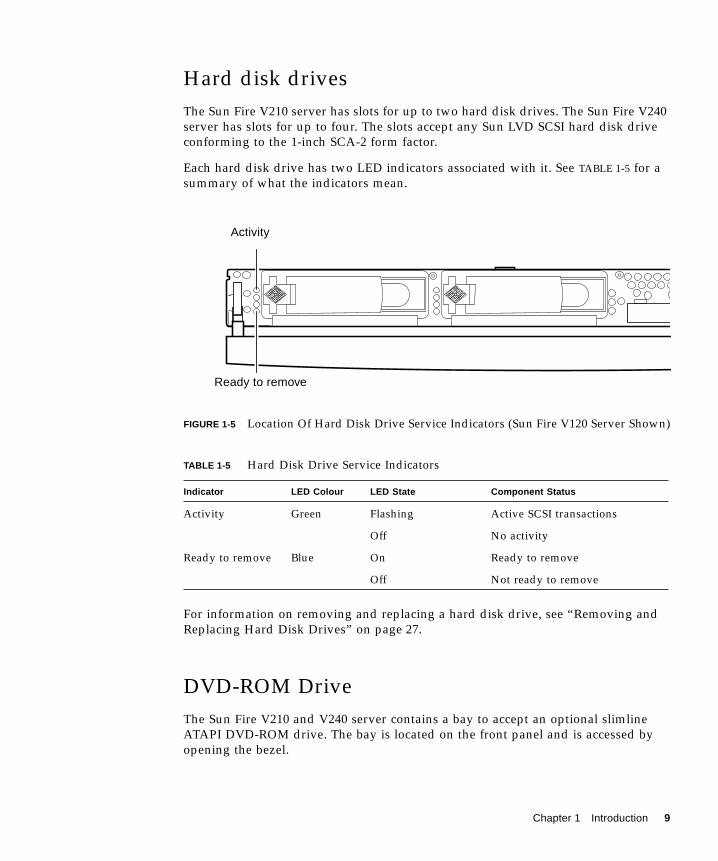
Hard disk drivesThe Sun Fire V210 server has slots for up to two hard disk drives. The Sun Fire V240server has slots for up to four. The slots accept any Sun LVD SCSI hard disk driveconforming to the 1-inch SCA-2 form factor.
Each hard disk drive has two LED indicators associated with it. See TABLE 1-5 for asummary of what the indicators mean.
FIGURE 1-5 Location Of Hard Disk Drive Service Indicators (Sun Fire V120 Server Shown)
For information on removing and replacing a hard disk drive, see “Removing andReplacing Hard Disk Drives” on page 27.
DVD-ROM DriveThe Sun Fire V210 and V240 server contains a bay to accept an optional slimlineATAPI DVD-ROM drive. The bay is located on the front panel and is accessed byopening the bezel.
TABLE 1-5 Hard Disk Drive Service Indicators
Indicator LED Colour LED State Component Status
Activity Green Flashing Active SCSI transactions
Off No activity
Ready to remove Blue On Ready to remove
Off Not ready to remove
Activity
Ready to remove
Chapter 1 Introduction 9
For information on DVD-ROM drive installation, see “Removing And Replacing TheDVD-ROM Drive” on page 32.
System Configuration Card (SCC)The system configuration card is housed in a slot behind the front bezel, next to theOn/Standby switch (see FIGURE 1-4). The card contains unique network identityinformation, including the MAC address and hostid (known as the idprom), and theOpenBoot™ PROM configuration (also known as nvram).
The server attempts to access the SCC while booting.
■ If a properly formatted card is not present in the reader, the system will not boot.
■ If the content of the nvram section is invalid, the system will be initialized withits default nvram configuration.
■ If the content of the idprom section is invalid, OBP displays a warning messageand the system will not auto-boot Solaris. However, you can boot the system fromthe ok prompt using the boot command.
It is therefore essential that you store the SCC safely if you have to remove it fromthe server, and replace it before restarting the system.
For more information, see “Swapping the System Configuration Card BetweenServers” on page 25.
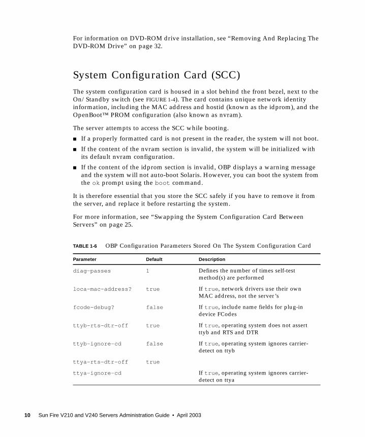
TABLE 1-6 OBP Configuration Parameters Stored On The System Configuration Card
Parameter Default Description
diag-passes 1 Defines the number of times self-testmethod(s) are performed
loca-mac-address? true If true, network drivers use their ownMAC address, not the server’s
fcode-debug? false If true, include name fields for plug-indevice FCodes
ttyb-rts-dtr-off true If true, operating system does not assertttyb and RTS and DTR
ttyb-ignore-cd false If true, operating system ignores carrier-detect on ttyb
ttya-rts-dtr-off true
ttya-ignore-cd If true, operating system ignores carrier-detect on ttya
10 Sun Fire V210 and V240 Servers Administration Guide • April 2003
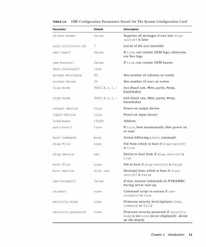
silent-mode? false Suppress all messages if true and diag-switch? is false
scsi-initiator-id 7 scsi-id of the scsi controller
oem-logo? false If true, use custom OEM logo, otherwise,use Sun logo
oem-banner? false If true, use custom OEM banner
ansi-terminal? true
screen-#columns 80 Sets number of columns on screen
screen-#rows 34 Sets number of rows on screen
ttya-mode 9600,8,n,1,- ttya (baud rate, #bits, parity, #stop,handshake)
ttyb-mode 9600,8,n,1,- ttyb (baud rate, #bits, parity, #stop,handshake)
output-device ttya Power-on output device
input-device ttya Power-on input device
load-base 16384 Address
auto-boot? true If true, boot automatically after power onor reset
boot-command boot Action following a boot command
diag-file none File from which to boot if diag-switch?is true
diag-device net Device to boot from if diag-switch? istrue
boot-file none File to boot if diag-switch? is false
boot-device disk net Device(s) from which to boot if diag-switch? is false
use-nvramrc? false If true, execute commands in NVRAMRCduring server start-up
nvramrc none Command script to execute if use-nvramrc? is true
security-mode none Firmware security level (options: none,command, or full)
security-password none Firmware security password if security-mode is not none (never displayed) - do notset this directly
TABLE 1-6 OBP Configuration Parameters Stored On The System Configuration Card
Parameter Default Description
Chapter 1 Introduction 11
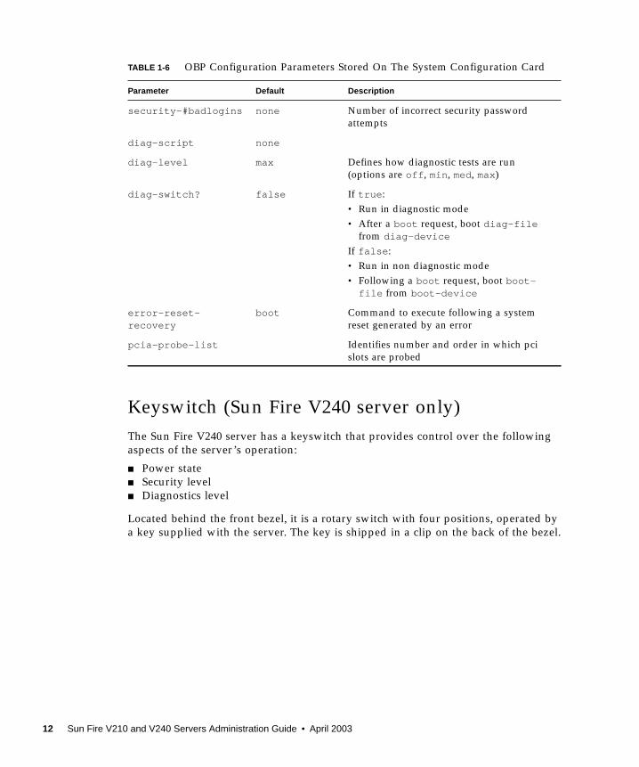
Keyswitch (Sun Fire V240 server only)The Sun Fire V240 server has a keyswitch that provides control over the followingaspects of the server’s operation:
■ Power state■ Security level■ Diagnostics level
Located behind the front bezel, it is a rotary switch with four positions, operated bya key supplied with the server. The key is shipped in a clip on the back of the bezel.
security-#badlogins none Number of incorrect security passwordattempts
diag-script none
diag-level max Defines how diagnostic tests are run(options are off, min, med, max)
diag-switch? false If true:• Run in diagnostic mode• After a boot request, boot diag-file
from diag-device
If false:• Run in non diagnostic mode• Following a boot request, boot boot-file from boot-device
error-reset-recovery
boot Command to execute following a systemreset generated by an error
pcia-probe-list Identifies number and order in which pcislots are probed
TABLE 1-6 OBP Configuration Parameters Stored On The System Configuration Card
Parameter Default Description
12 Sun Fire V210 and V240 Servers Administration Guide • April 2003
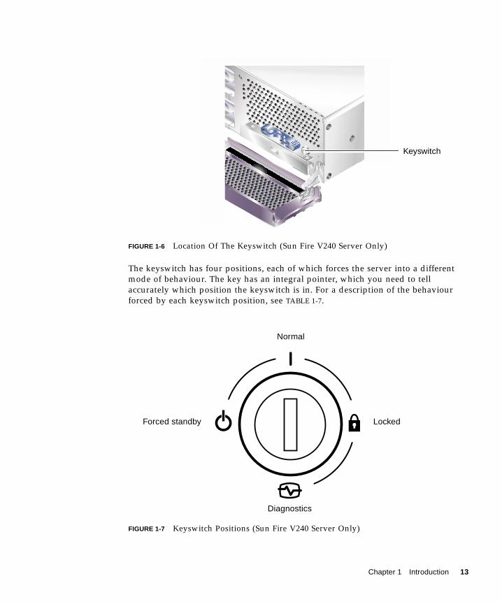
FIGURE 1-6 Location Of The Keyswitch (Sun Fire V240 Server Only)
The keyswitch has four positions, each of which forces the server into a differentmode of behaviour. The key has an integral pointer, which you need to tellaccurately which position the keyswitch is in. For a description of the behaviourforced by each keyswitch position, see TABLE 1-7.
FIGURE 1-7 Keyswitch Positions (Sun Fire V240 Server Only)
Keyswitch
Forced standby
Normal
Locked
Diagnostics
Chapter 1 Introduction 13
Keyswitch positions and the behaviours they force are given in TABLE 1-7.
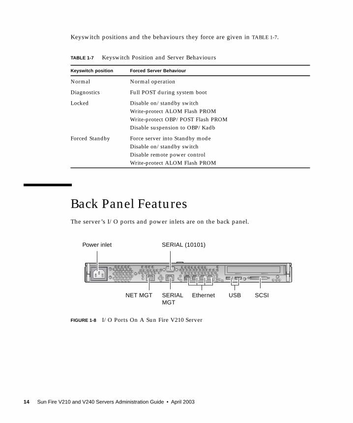
Back Panel FeaturesThe server’s I/O ports and power inlets are on the back panel.
FIGURE 1-8 I/O Ports On A Sun Fire V210 Server
TABLE 1-7 Keyswitch Position and Server Behaviours
Keyswitch position Forced Server Behaviour
Normal Normal operation
Diagnostics Full POST during system boot
Locked Disable on/standby switchWrite-protect ALOM Flash PROMWrite-protect OBP/POST Flash PROMDisable suspension to OBP/Kadb
Forced Standby Force server into Standby modeDisable on/standby switchDisable remote power controlWrite-protect ALOM Flash PROM
Power inlet
NET MGT
SERIAL (10101)
SERIALMGT
Ethernet USB SCSI
14 Sun Fire V210 and V240 Servers Administration Guide • April 2003
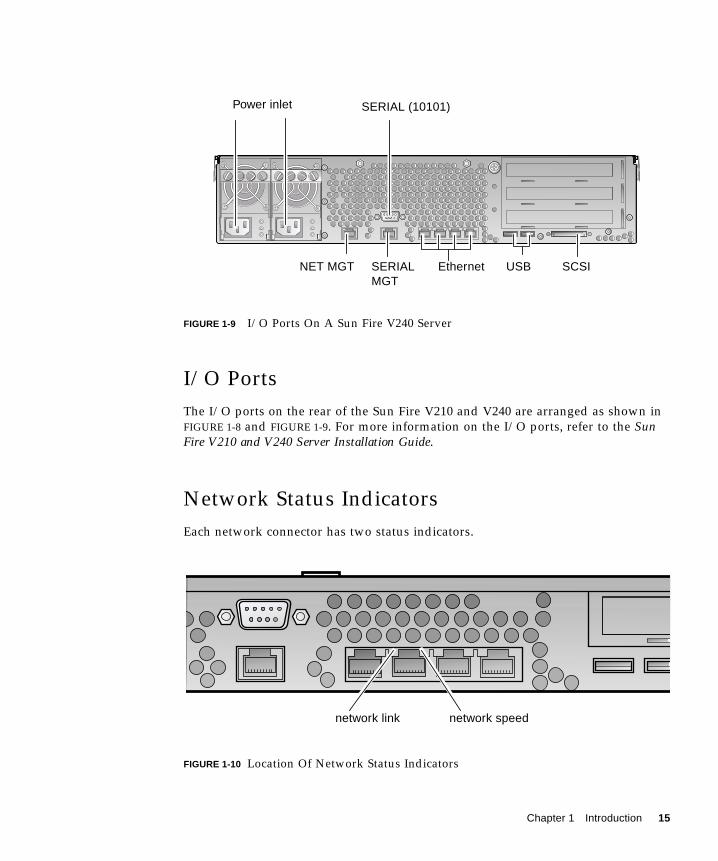
FIGURE 1-9 I/O Ports On A Sun Fire V240 Server
I/O PortsThe I/O ports on the rear of the Sun Fire V210 and V240 are arranged as shown inFIGURE 1-8 and FIGURE 1-9. For more information on the I/O ports, refer to the SunFire V210 and V240 Server Installation Guide.
Network Status IndicatorsEach network connector has two status indicators.
FIGURE 1-10 Location Of Network Status Indicators
Power inlet SERIAL (10101)
SERIALMGT
NET MGT Ethernet USB SCSI
network link network speed
Chapter 1 Introduction 15
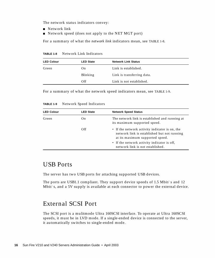
The network status indicators convey:
■ Network link■ Network speed (does not apply to the NET MGT port)
For a summary of what the network link indicators mean, see TABLE 1-8.
For a summary of what the network speed indicators mean, see TABLE 1-9.
USB PortsThe server has two USB ports for attaching supported USB devices.
The ports are USB1.1 compliant. They support device speeds of 1.5 Mbit/s and 12Mbit/s, and a 5V supply is available at each connector to power the external device.
External SCSI PortThe SCSI port is a mulitmode Ultra 160SCSI interface. To operate at Ultra 160SCSIspeeds, it must be in LVD mode. If a single-ended device is connected to the server,it automatically switches to single-ended mode.
TABLE 1-8 Network Link Indicators
LED Colour LED State Network Link Status
Green On Link is established.
Blinking Link is transferring data.
Off Link is not established.
TABLE 1-9 Network Speed Indicators
LED Colour LED State Network Speed Status
Green On The network link is established and running atits maximum supported speed.
Off • If the network activity indicator is on, thenetwork link is established but not runningat its maximum supported speed.
• If the network activity indicator is off,network link is not established.
16 Sun Fire V210 and V240 Servers Administration Guide • April 2003
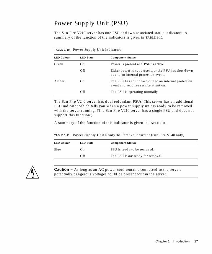
Power Supply Unit (PSU)The Sun Fire V210 server has one PSU and two associated status indicators. Asummary of the function of the indicators is given in TABLE 1-10.
The Sun Fire V240 server has dual redundant PSUs. This server has an additionalLED indicator which tells you when a power supply unit is ready to be removedwith the server running. (The Sun Fire V210 server has a single PSU and does notsupport this function.)
A summary of the function of this indicator is given in TABLE 1-11.
Caution – As long as an AC power cord remains connected to the server,potentially dangerous voltages could be present within the server.
TABLE 1-10 Power Supply Unit Indicators
LED Colour LED State Component Status
Green On Power is present and PSU is active.
Off Either power is not present, or the PSU has shut downdue to an internal protection event.
Amber On The PSU has shut down due to an internal protectionevent and requires service attention.
Off The PSU is operating normally.
TABLE 1-11 Power Supply Unit Ready To Remove Indicator (Sun Fire V240 only)
LED Colour LED State Component Status
Blue On PSU is ready to be removed.
Off The PSU is not ready for removal.
Chapter 1 Introduction 17
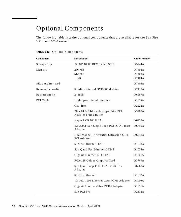
Optional ComponentsThe following table lists the optional components that are available for the Sun FireV210 and V240 server.
TABLE 1-12 Optional Components
Component Description Order Number
Storage disk 36 GB 10000 RPM 1-inch SCSI X5244A
Memory 256 MB512 MB1 GB
X7402AX7403AX7404A
SSL daughter card X7405A
Removable media Slimline internal DVD-ROM drive X7410A
Rackmount kit 24-inch X6967A
PCI Cards High Speed Serial Interface X1155A
Cauldron X2222A
PGX 64 8/24-bit colour graphics PCIAdapter Frame Buffer
X3768A
Jasper LVD 160 HBA X6758A
ISP 2200F Sun Single Loop PCI FC-AL HostAdapter
X6799A
Dual channel Differential Ultrawide SCSIPCI Adapter
X6541A
SunFastEthernet FE/P X1033A
Sun Quad FastEthernet QFE/P X1034A
Gigabit Ethernet 2.0 GBE/P X1141A
PGX-128 Colour Graphics Card X3769A
Sun Dual Loop PCI FC-AL 2GB HostAdapter
X6768A
SunFastEthernet X1032A
10/100/1000 Ethernet-Cat5 PCI66 Adapter X1150A
Gigabit Ethernet-Fiber PCI66 Adapter X1151A
Sun PCI Pro X2132A
18 Sun Fire V210 and V240 Servers Administration Guide • April 2003
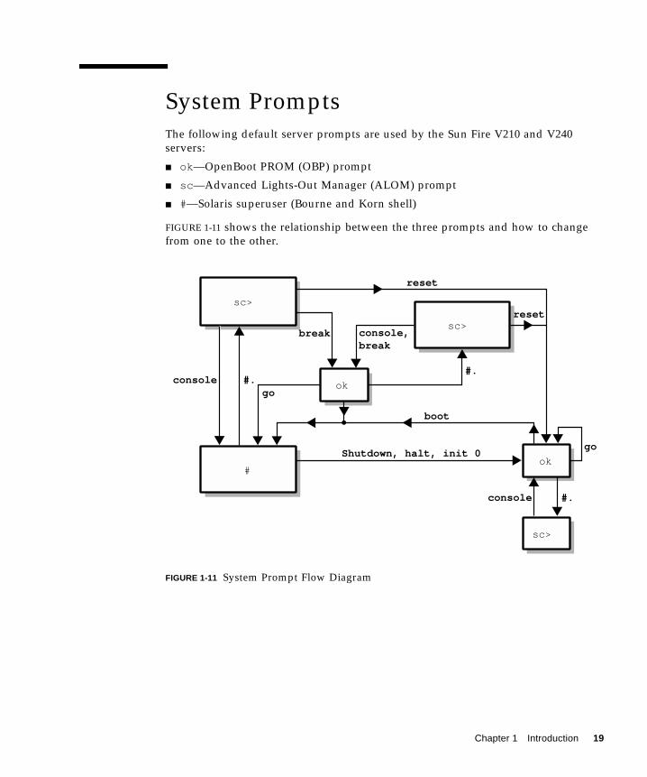
System PromptsThe following default server prompts are used by the Sun Fire V210 and V240servers:
■ ok—OpenBoot PROM (OBP) prompt
■ sc—Advanced Lights-Out Manager (ALOM) prompt
■ #—Solaris superuser (Bourne and Korn shell)
FIGURE 1-11 shows the relationship between the three prompts and how to changefrom one to the other.
FIGURE 1-11 System Prompt Flow Diagram
ok
ok
go
sc>
sc>
Shutdown, halt, init 0
boot
break
console
console,break
reset
go
reset
sc>
#.#.
#.console
#
Chapter 1 Introduction 19

20 Sun Fire V210 and V240 Servers Administration Guide • April 2003
CHAPTER 2
Removing and ReplacingComponents
This chapter tells you how to remove and replace the components that are locatedbehind the server’s front bezel. The procedures documented in this chapter do notrequire the attention of qualified service personnel.
Caution – Read the section, “Avoiding Electrostatic Discharge” on page 22, andwear a properly grounded antistatic strap, before you carry out any of theprocedures in this section.
The chapter contains the following sections:
■ “Replaceable Components” on page 22
■ “Avoiding Electrostatic Discharge” on page 22
■ “Swapping the System Configuration Card Between Servers” on page 25
■ “Removing and Replacing Hard Disk Drives” on page 27
■ “Removing And Replacing The DVD-ROM Drive” on page 32
21
Replaceable ComponentsOpen the bezel down to access these components:
■ System Configuration Card
■ Hard disk drives
■ DVD-ROM drive
Note – Access to any other component requires the removal of the server’s lid, andinvolves procedures that must be carried out by trained personnel only.
Avoiding Electrostatic Discharge
▼ To Avoid Electrostatic Discharge While WorkingOn The Front Panel
1. Attach one end of the antistatic wrist strap to your wrist.
2. Attach the other end to a grounding stud on the rack or cabinet.
▼ To Open The Front Bezel1. Ensure that you are properly grounded.
See “To Avoid Electrostatic Discharge While Working On The Front Panel” onpage 22.
22 Sun Fire V210 and V240 Servers Administration Guide • April 2003
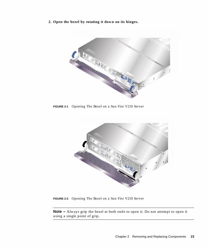
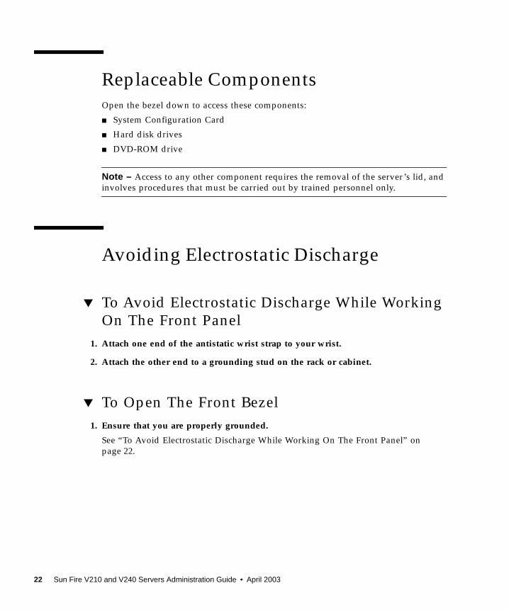
2. Open the bezel by rotating it down on its hinges.
FIGURE 2-1 Opening The Bezel on a Sun Fire V210 Server
FIGURE 2-2 Opening The Bezel on a Sun Fire V210 Server
Note – Always grip the bezel at both ends to open it. Do not attempt to open itusing a single point of grip.
Chapter 2 Removing and Replacing Components 23
Controlling Server PowerBefore you remove or replace a system configuration card or DVD-ROM drive, theserver must be powered down.
For detailed information on controlling server power with software, refer to theALOM Online Documentation which is contained on the Sun Fire V210 and V240Servers Documentation CD.
▼ To Power On Using the On/Standby Switch
Caution – Never move the system when the system power is on. Movement cancause catastrophic disk drive failure. Always power off the system before moving it.
1. Connect the server to an AC power source.
Once connected, the server automatically goes into Standby power mode.
2. Turn on power to any peripherals and external storage devices you have connectedto the server.
Read the documentation supplied with the device for specific instructions.
3. Open the front bezel.
4. Sun Fire V240 only: insert the system key into the keyswitch and set it to theNormal or Diagnostics position.
5. Press the On/Standby switch.
6. Sun Fire V240 only:
a. Turn the key switch to the Locked position.
This prevents anyone from accidentally powering off the system.
b. Remove the system key from the keyswitch and store it in the clip on the backof the bezel.
7. Close the front bezel.
24 Sun Fire V210 and V240 Servers Administration Guide • April 2003
▼ To Power Off Using The On/Standby Switch
Note – Applications running on the Solaris operating environment can be adverselyaffected by a poorly executed system shutdown. Make sure you have gracefully shutdown any applications before powering off the system.
1. Notify users that the system will be powered down.
2. Back up the system files and data, if necessary.
3. Sun Fire V240 only: ensure that the keyswitch is in the Normal or Diagnosticsposition.
4. Press and release the On/Standby switch behind the front bezel.
The system begins an orderly software system shutdown.
Note – Pressing and releasing the On/Standby switch initiates an orderly softwareshutdown. Pressing and holding the switch for four seconds causes an immediatehardware shutdown. Whenever possible, initiate an orderly shutdown. Forcing animmediate hardware shutdown can corrupt the disk drive and cause loss of data.
5. Wait for the front panel green LED to go out.
6. Sun Fire V240 only: remove the system key from the keyswitch and store it in theclip on the back of the front bezel.
7. Close the front bezel.
Swapping the System ConfigurationCard Between Servers
▼ To Swap the System Configuration CardBetween Servers
1. Power down both servers.
See “Controlling Server Power” on page 24.
Chapter 2 Removing and Replacing Components 25
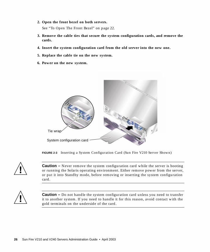
2. Open the front bezel on both servers.
See “To Open The Front Bezel” on page 22.
3. Remove the cable ties that secure the system configuration cards, and remove thecards.
4. Insert the system configuration card from the old server into the new one.
5. Replace the cable tie on the new system.
6. Power on the new system.
FIGURE 2-3 Inserting a System Configuration Card (Sun Fire V210 Server Shown)
Caution – Never remove the system configuration card while the server is bootingor running the Solaris operating environment. Either remove power from the server,or put it into Standby mode, before removing or inserting the system configurationcard.
Caution – Do not handle the system configuration card unless you need to transferit to another system. If you need to handle it for this reason, avoid contact with thegold terminals on the underside of the card.
Tie wrap
System configuration card
26 Sun Fire V210 and V240 Servers Administration Guide • April 2003
Removing and Replacing Hard DiskDrives
Caution – The server and hard disk drives contain electronic parts that areextremely sensitive to static electricity. Wear a grounded antistatic wrist strap whenyou carry out this procedure.
Removing A Hard Disk DriveThe hard disk drives are hot-pluggable modules. If more than one is fitted, you caninstall or remove a hard disk drive without powering off the server or removing itfrom the rack.
However, you do need to make sure that no system or application software is usinga hard disk drive when you remove it.
Note – If you intend to remove a hard disk drive with Solaris running, follow theinstructions in “Removing a SCSI Hard Disk Drive With Solaris Running” onpage 30 before performing the steps below.
1. Open the front bezel.
See “To Open The Front Bezel” on page 22.
2. Check that the blue indicator LED is lit on the hard disk drive.
The blue LED comes on when the hard disk drive is ready to remove.
3. Slide the catch at the front of the hard disk drive to the right.
This releases the handle on the front of the hard disk drive.
4. Pull the handle and remove the hard disk drive from the server by sliding it outfrom its bay.
Chapter 2 Removing and Replacing Components 27

Installing A Hard Disk Drive
Caution – The server and hard disk drives contain electronic parts that areextremely sensitive to static electricity. Wear a grounded antistatic wrist strap whenyou carry out this procedure.
FIGURE 2-4 Inserting a Hard Disk Drive (Sun Fire V210 Server Shown)
5. Slide the catch on the front of the hard disk to the right.
This releases a handle on the front of the hard disk drive. The lever must be openbefore you insert the hard disk drive. If it is not, the hard disk drive will not engagewith the server correctly.
6. Slide the hard disk drive into its bay at the front of the server.
Push it in firmly until the metal lever starts to close. This indicates that the hard diskdrive has engaged with its connector in the server.
7. Push the metal lever until the disk drive clicks into place.
8. Close the bezel.
If you have installed a hard disk drive with Solaris running, now perform the stepsin “Installing a SCSI Hard Disk Drive With Solaris Running” on page 29.
28 Sun Fire V210 and V240 Servers Administration Guide • April 2003
Installing a SCSI Hard Disk Drive With SolarisRunningBefore performing the instructions in this section, install the Hard Disk Drive byfollowing the instructions in “Installing A Hard Disk Drive” on page 28.
Use the instructions below in conjunction with the cfgadm(M) man page.
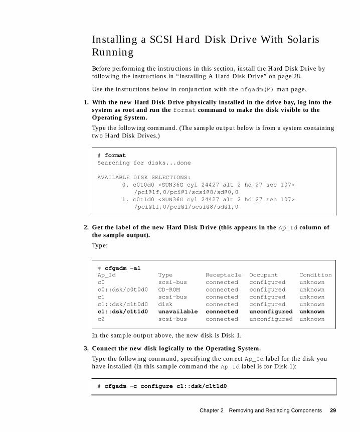
1. With the new Hard Disk Drive physically installed in the drive bay, log into thesystem as root and run the format command to make the disk visible to theOperating System.
Type the following command. (The sample output below is from a system containingtwo Hard Disk Drives.)
2. Get the label of the new Hard Disk Drive (this appears in the Ap_Id column ofthe sample output).
Type:
In the sample output above, the new disk is Disk 1.
3. Connect the new disk logically to the Operating System.
Type the following command, specifying the correct Ap_Id label for the disk youhave installed (in this sample command the Ap_Id label is for Disk 1):
# formatSearching for disks...done
AVAILABLE DISK SELECTIONS:0. c0t0d0 <SUN36G cyl 24427 alt 2 hd 27 sec 107>
/pci@1f,0/pci@1/scsi@8/sd@0,01. c0t1d0 <SUN36G cyl 24427 alt 2 hd 27 sec 107>
/pci@1f,0/pci@1/scsi@8/sd@1,0
# cfgadm -c configure c1::dsk/c1t1d0
# cfgadm -alAp_Id Type Receptacle Occupant Conditionc0 scsi-bus connected configured unknownc0::dsk/c0t0d0 CD-ROM connected configured unknownc1 scsi-bus connected configured unknownc1::dsk/c1t0d0 disk connected configured unknownc1::dsk/c1t1d0 unavailable connected unconfigured unknownc2 scsi-bus connected unconfigured unknown
Chapter 2 Removing and Replacing Components 29
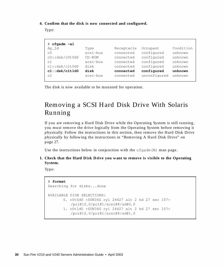
4. Confirm that the disk is now connected and configured.
Type:
The disk is now available to be mounted for operation.
Removing a SCSI Hard Disk Drive With SolarisRunningIf you are removing a Hard Disk Drive while the Operating System is still running,you must remove the drive logically from the Operating System before removing itphysically. Follow the instructions in this section, then remove the Hard Disk Drivephysically by following the instructions in “Removing A Hard Disk Drive” onpage 27.
Use the instructions below in conjunction with the cfgadm(M) man page.
1. Check that the Hard Disk Drive you want to remove is visible to the OperatingSystem.
Type:
# formatSearching for disks...done
AVAILABLE DISK SELECTIONS:0. c0t0d0 <SUN36G cyl 24427 alt 2 hd 27 sec 107>
/pci@1f,0/pci@1/scsi@8/sd@0,01. c0t1d0 <SUN36G cyl 24427 alt 2 hd 27 sec 107>
/pci@1f,0/pci@1/scsi@8/sd@1,0
# cfgadm -alAp_Id Type Receptacle Occupant Conditionc0 scsi-bus connected configured unknownc0::dsk/c0t0d0 CD-ROM connected configured unknownc1 scsi-bus connected configured unknownc1::dsk/c1t0d0 disk connected configured unknownc1::dsk/c1t1d0 disk connected configured unknownc2 scsi-bus connected unconfigured unknown
30 Sun Fire V210 and V240 Servers Administration Guide • April 2003
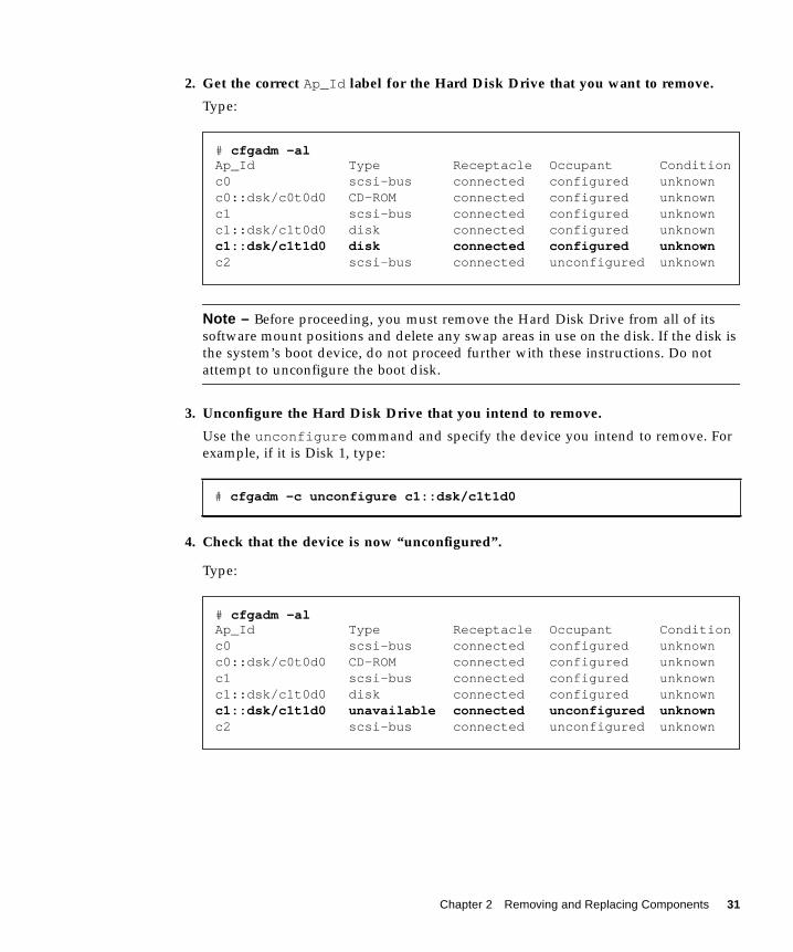
2. Get the correct Ap_Id label for the Hard Disk Drive that you want to remove.
Type:
Note – Before proceeding, you must remove the Hard Disk Drive from all of itssoftware mount positions and delete any swap areas in use on the disk. If the disk isthe system’s boot device, do not proceed further with these instructions. Do notattempt to unconfigure the boot disk.
3. Unconfigure the Hard Disk Drive that you intend to remove.
Use the unconfigure command and specify the device you intend to remove. Forexample, if it is Disk 1, type:
4. Check that the device is now “unconfigured”.
Type:
# cfgadm -c unconfigure c1::dsk/c1t1d0
# cfgadm -alAp_Id Type Receptacle Occupant Conditionc0 scsi-bus connected configured unknownc0::dsk/c0t0d0 CD-ROM connected configured unknownc1 scsi-bus connected configured unknownc1::dsk/c1t0d0 disk connected configured unknownc1::dsk/c1t1d0 disk connected configured unknownc2 scsi-bus connected unconfigured unknown
# cfgadm -alAp_Id Type Receptacle Occupant Conditionc0 scsi-bus connected configured unknownc0::dsk/c0t0d0 CD-ROM connected configured unknownc1 scsi-bus connected configured unknownc1::dsk/c1t0d0 disk connected configured unknownc1::dsk/c1t1d0 unavailable connected unconfigured unknownc2 scsi-bus connected unconfigured unknown
Chapter 2 Removing and Replacing Components 31
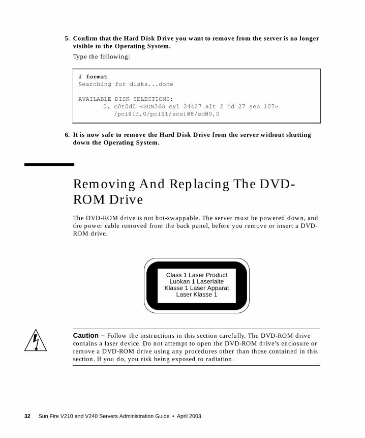
5. Confirm that the Hard Disk Drive you want to remove from the server is no longervisible to the Operating System.
Type the following:
6. It is now safe to remove the Hard Disk Drive from the server without shuttingdown the Operating System.
Removing And Replacing The DVD-ROM DriveThe DVD-ROM drive is not hot-swappable. The server must be powered down, andthe power cable removed from the back panel, before you remove or insert a DVD-ROM drive.
Caution – Follow the instructions in this section carefully. The DVD-ROM drivecontains a laser device. Do not attempt to open the DVD-ROM drive’s enclosure orremove a DVD-ROM drive using any procedures other than those contained in thissection. If you do, you risk being exposed to radiation.
# formatSearching for disks...done
AVAILABLE DISK SELECTIONS:0. c0t0d0 <SUN36G cyl 24427 alt 2 hd 27 sec 107>
/pci@1f,0/pci@1/scsi@8/sd@0,0
Class 1 Laser ProductLuokan 1 Laserlaite
Klasse 1 Laser ApparatLaser Klasse 1
32 Sun Fire V210 and V240 Servers Administration Guide • April 2003
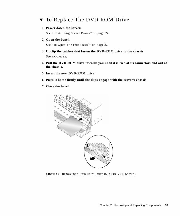
▼ To Replace The DVD-ROM Drive1. Power down the server.
See “Controlling Server Power” on page 24.
2. Open the bezel.
See “To Open The Front Bezel” on page 22.
3. Unclip the catches that fasten the DVD-ROM drive to the chassis.
See FIGURE 2-5.
4. Pull the DVD-ROM drive towards you until it is free of its connectors and out ofthe chassis.
5. Insert the new DVD-ROM drive.
6. Press it home firmly until the clips engage with the server’s chassis.
7. Close the bezel.
FIGURE 2-5 Removing a DVD-ROM Drive (Sun Fire V240 Shown)
Chapter 2 Removing and Replacing Components 33
Sun Fire V240 Server: Removing andReplacing a Power Supply UnitThe Sun Fire V240 server has dual-redundant power supplies. You can swap onepower supply while the other is still running.
The Sun Fire V210 server has a single power supply. Swapping it requires theattention of qualified service personnel. Refer to the Sun Fire V210 and V240 ServersParts Replacement Manual which is contained on the Sun Fire V210 and V240Servers Documentation CD.
▼ To Remove a Power Supply Unit1. At the ALOM prompt, type:
Where x is the power supply unit identifier, 0 or 1.
When the blue ok to remove LED lights on the back of the power supply unit,remove it.
2. Pull down on the PSU lever.
3. Withdraw the PSU from the server’s chassis.
▼ To Replace a Power Supply Unit1. Slide the PSU into the back of the server until it stops.
Do not push the PSU lever closed until the PSU is all the way in.
2. Press the PSU lever until it clicks home.
This engages the PSU with the power distribution board inside the server.
sc> removefru -y PSx
34 Sun Fire V210 and V240 Servers Administration Guide • April 2003
3. At the ALOM prompt, type:
Where x is the power supply unit identifier, 0 or 1.
sc> poweron PSx
Chapter 2 Removing and Replacing Components 35

36 Sun Fire V210 and V240 Servers Administration Guide • April 2003
CHAPTER 3
Sun™ Advanced Lights-OutManager
This chapter gives an overview of the Sun Advanced Lights-Out Manager (ALOM)software. The chapter contains:
■ “Sun™ Advanced Lights-Out Manager 1.0 (ALOM)” on page 38
■ “ALOM Management Ports” on page 39
■ “Setting the admin Password” on page 39
■ “Basic ALOM Functions” on page 40
37
Sun™ Advanced Lights-Out Manager1.0 (ALOM)Both the Sun Fire V210 server and the Sun Fire V240 server are shipped with Sun™Advanced Lights Out Manager (ALOM) 1.0 installed. The system console is directedto ALOM by default and is configured to show server console information onstartup.
ALOM enables you to monitor and control your server over either a serialconnection (using the SERIAL MGT port), or Ethernet connection (using the NETMGT port). For information on configuring an Ethernet connection, refer to theALOM Online Help.
Note – The ALOM serial port, labelled SERIAL MGT, is for server managementonly. If you need a general purpose serial port, use the serial port labeled 10101.
ALOM can be configured to send email notification of hardware failures and otherevents related to the server or to ALOM.
The ALOM circuitry uses standby power from the server. This means that:
■ ALOM is active as soon as the server is connected to a power source, and untilpower is removed by unplugging the power cable.
■ ALOM firmware and software continue to be effective when the server operatingsystem goes offline.
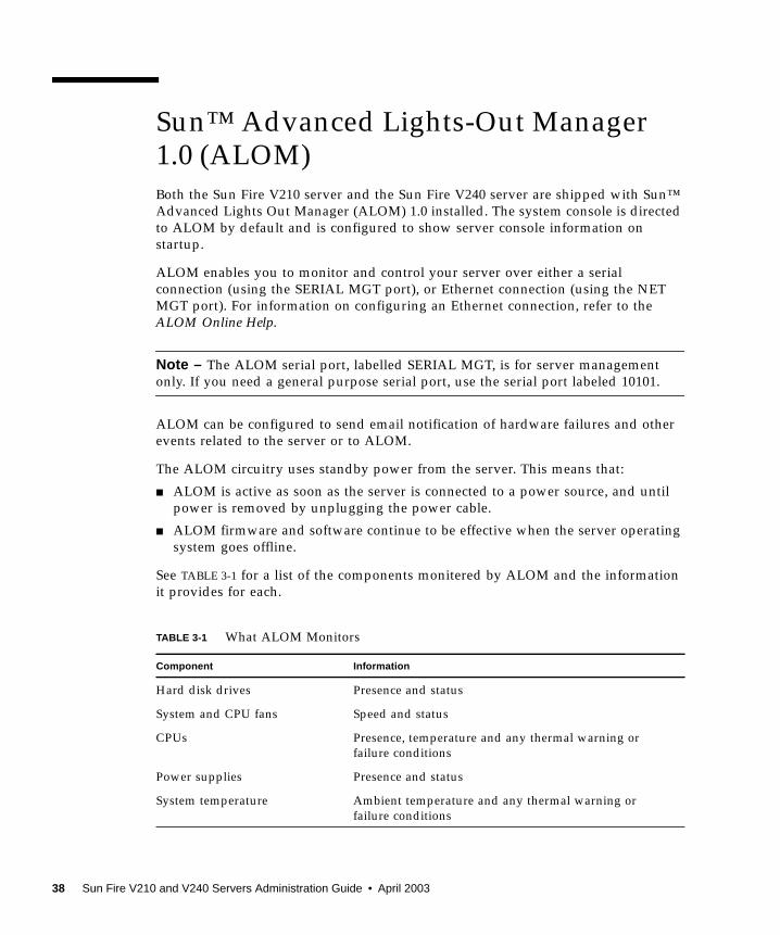
See TABLE 3-1 for a list of the components monitered by ALOM and the informationit provides for each.
TABLE 3-1 What ALOM Monitors
Component Information
Hard disk drives Presence and status
System and CPU fans Speed and status
CPUs Presence, temperature and any thermal warning orfailure conditions
Power supplies Presence and status
System temperature Ambient temperature and any thermal warning orfailure conditions
38 Sun Fire V210 and V240 Servers Administration Guide • April 2003
ALOM Management PortsThe default management port is labeled SERIAL MGT. This port uses an RJ-45connector and is for server management only—it supports only ASCII connections toan external console. Use this port when you first begin to operate the server.
Another serial port—labeled 10101— is available for general purpose serial datatransfer. This port uses a DB-9 connector. For information on pinouts, refer to theSun Fire V210 and V240 Server Installation Guide.
In addition, the server has one 10Base-T Ethernet management domain interface,labelled NET MGT. To use this port, ALOM configuration is required. Forinformation, see the ALOM Online Help which is included on the Sun Fire V210 andV240 Server Documentation CD.
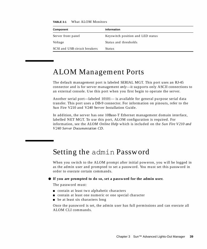
Setting the admin PasswordWhen you switch to the ALOM prompt after initial poweron, you will be logged inas the admin user and prompted to set a password. You must set this password inorder to execute certain commands.
● If you are prompted to do so, set a password for the admin user.
The password must:
■ contain at least two alphabetic characters■ contain at least one numeric or one special character■ be at least six characters long
Once the password is set, the admin user has full permissions and can execute allALOM CLI commands.
Server front panel Keyswitch position and LED status
Voltage Status and thresholds
SCSI and USB circuit breakers Status
TABLE 3-1 What ALOM Monitors
Component Information
Chapter 3 Sun™ Advanced Lights-Out Manager 39
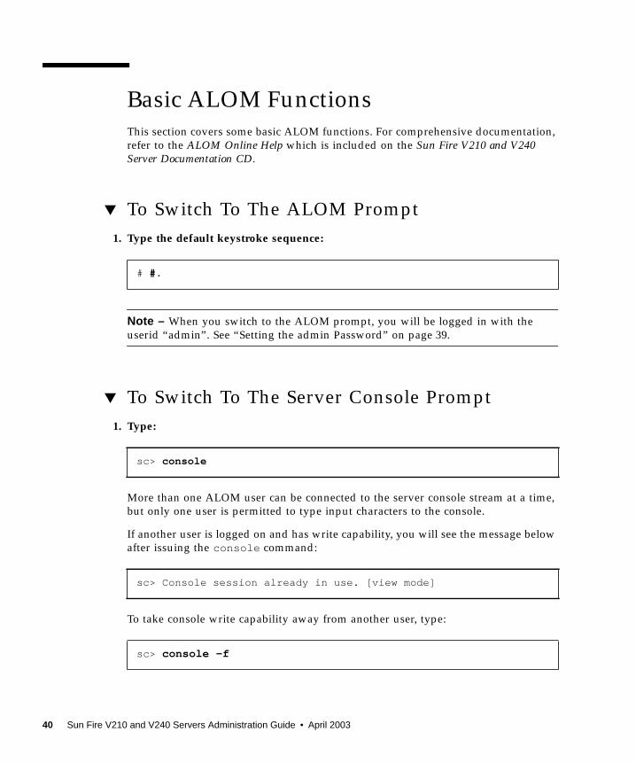
Basic ALOM FunctionsThis section covers some basic ALOM functions. For comprehensive documentation,refer to the ALOM Online Help which is included on the Sun Fire V210 and V240Server Documentation CD.
▼ To Switch To The ALOM Prompt1. Type the default keystroke sequence:
Note – When you switch to the ALOM prompt, you will be logged in with theuserid “admin”. See “Setting the admin Password” on page 39.
▼ To Switch To The Server Console Prompt1. Type:
More than one ALOM user can be connected to the server console stream at a time,but only one user is permitted to type input characters to the console.
If another user is logged on and has write capability, you will see the message belowafter issuing the console command:
To take console write capability away from another user, type:
# #.
sc> console
sc> Console session already in use. [view mode]
sc> console -f
40 Sun Fire V210 and V240 Servers Administration Guide • April 2003
CHAPTER 4
Sun Management Center
This chapter describes SunMC. The chapter contains the sections:
■ “Sun Management Center” on page 42
■ “Hardware Diagnostic Suite” on page 44
41
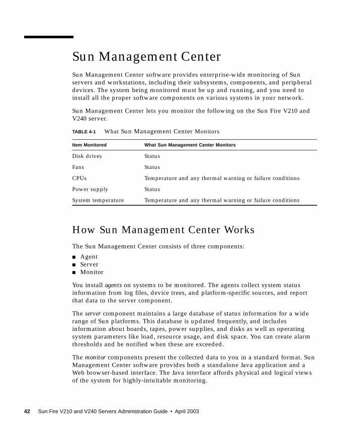
Sun Management CenterSun Management Center software provides enterprise-wide monitoring of Sunservers and workstations, including their subsystems, components, and peripheraldevices. The system being monitored must be up and running, and you need toinstall all the proper software components on various systems in your network.
Sun Management Center lets you monitor the following on the Sun Fire V210 andV240 server.
How Sun Management Center WorksThe Sun Management Center consists of three components:
■ Agent■ Server■ Monitor
You install agents on systems to be monitored. The agents collect system statusinformation from log files, device trees, and platform-specific sources, and reportthat data to the server component.
The server component maintains a large database of status information for a widerange of Sun platforms. This database is updated frequently, and includesinformation about boards, tapes, power supplies, and disks as well as operatingsystem parameters like load, resource usage, and disk space. You can create alarmthresholds and be notified when these are exceeded.
The monitor components present the collected data to you in a standard format. SunManagement Center software provides both a standalone Java application and aWeb browser-based interface. The Java interface affords physical and logical viewsof the system for highly-intuitable monitoring.
TABLE 4-1 What Sun Management Center Monitors
Item Monitored What Sun Management Center Monitors
Disk drives Status
Fans Status
CPUs Temperature and any thermal warning or failure conditions
Power supply Status
System temperature Temperature and any thermal warning or failure conditions
42 Sun Fire V210 and V240 Servers Administration Guide • April 2003
Other Sun Management Center FeaturesSun Management Center software provides you with additional tools, which canoperate with management utilities made by other companies.
The tools are an informal tracking mechanism and the optional add-on, HardwareDiagnostics Suite.
Informal Tracking
Sun Management Center agent software must be loaded on any system you want tomonitor. However, the product lets you informally track a supported platform evenwhen the agent software has not been installed on it. In this case, you do not havefull monitoring capability, but you can add the system to your browser, have SunManagement Center periodically check whether it is up and running, and notify youif it goes out of commission.
Hardware Diagnostic Suite
The Hardware Diagnostic Suite is a package which you can purchase as an add-on toSun Management Center. The suite lets you exercise a system while it is still up andrunning in a production environment. See “Hardware Diagnostic Suite” on page 44for more information.
Interoperability With Third-Party Monitoring Tools
If you administer a heterogeneous network and use a third-party network-basedsystem monitoring or management tool, you may be able to take advantage of SunManagement Center software’s support for Tivoli Enterprise Console, BMC Patrol,and HP Openview.
Using Sun Management CenterSun Management Center software is aimed at system administrators who have largedata centers to monitor or other installations that have many computer platforms tomonitor. If you administer a smaller installation, you need to weigh SunManagement Center software’s benefits against the requirement of maintaining asignificant database (typically over 700 Mbytes) of system status information.
The servers to be monitored must be running , Sun Management Center relies on theSolaris operating environment for its operation.
Chapter 4 Sun Management Center 43
For detailed instructions, see the Sun Management Center Software User’s Guide.
Obtaining the Latest Information
For the latest information about this product, go to the Sun Management Center Website: http://www.sun.com/sunmanagementcenter.
Hardware Diagnostic SuiteThe Sun Management Center features an optional Hardware Diagnostic Suite, whichyou can purchase as an add-on. The Hardware Diagnostic Suite is designed toexercise a production system by running tests sequentially.
Sequential testing means the Hardware Diagnostic Suite has a low impact on thesystem. Unlike SunVTS, which stresses a system by consuming its resources withmany parallel tests (see “SunVTS” on page 48), the Hardware Diagnostic Suite letsthe server run other applications while testing proceeds.
When to Run Hardware Diagnostic SuiteThe best use of the Hardware Diagnostic Suite is to disclose a suspected orintermittent problem with a non-critical part on an otherwise functioning machine.Examples might include questionable disk drives or memory modules on a machinethat has ample or redundant disk and memory resources.
In cases like these, the Hardware Diagnostic Suite runs unobtrusively until itidentifies the source of the problem. The machine under test can be kept inproduction mode until and unless it must be shut down for repair. If the faulty partis hot-pluggable or hot-swappable, the entire diagnose-and-repair cycle can becompleted with minimal impact to system users.
Requirements for Using Hardware DiagnosticSuiteSince it is a part of Sun Management Center, you can only run Hardware DiagnosticSuite if you have set up your data center to run Sun Management Center. Thismeans you have to dedicate a master server to run the Sun Management Centerserver software that supports Sun Management Center software’s database of
44 Sun Fire V210 and V240 Servers Administration Guide • April 2003
platform status information. In addition, you must install and set up SunManagement Center agent software on the systems to be monitored. Finally, youneed to install the console portion of Sun Management Center software, whichserves as your interface to the Hardware Diagnostic Suite.
Instructions for setting up Sun Management Center, as well as for using theHardware Diagnostic Suite, can be found in the Sun Management Center SoftwareUser’s Guide.
Chapter 4 Sun Management Center 45

46 Sun Fire V210 and V240 Servers Administration Guide • April 2003
CHAPTER 5
Sun VTS
This chapter describes SunVTS. The chapter contains the following sections:
■ “SunVTS” on page 48
47
SunVTSSunVTS is a software suite that performs system and subsystem stress testing. Youcan view and control a SunVTS session over a network. Using a remote machine,you can view the progress of a testing session, change testing options, and control alltesting features of another machine on the network.
You can run SunVTS software in three different test modes:
■ Connection mode verifies the presence of device controllers on all subsystems. Thistypically takes no more than a few minutes and is a good way to “sanity check”system connections.
■ Functional mode exercises only the specific subsystems you choose. This is thedefault mode.
■ Auto Config mode automatically detects all subsystems and exercises them in oneof two ways:
■ Confidence testing – performs one pass of tests on all subsystems, and thenstops. For typical system configurations, this requires one or two hours.
■ Comprehensive testing – tests all subsystems repeatedly for up to 24 hours.
Since SunVTS software can run many tests in parallel and consume many systemresources, you should take care when using it on a production system. If you arestress-testing a system using SunVTS software’s Comprehensive test mode, do notrun anything else on that system at the same time.
A server must be running the Solaris operating environment for SunVTS software tobe able to test it. Since SunVTS software packages are optional, they may not beinstalled on your system. See “To Find Out Whether SunVTS Is Installed” on page 50for instructions.
SunVTS Software and SecurityDuring SunVTS software installation, you must choose between Basic or SunEnterprise Authentication Mechanism (SEAM) security. Basic security uses a localsecurity file in the SunVTS installation directory to limit the users, groups, and hostspermitted to use SunVTS software. SEAM security is based on the standard networkauthentication protocol Kerberos and provides secure user authentication, dataintegrity and privacy for transactions over networks.
48 Sun Fire V210 and V240 Servers Administration Guide • April 2003
If your site uses SEAM security, you must have the SEAM client and server softwareinstalled in your networked environment and configured properly in both Solarisand SunVTS software. If your site does not use SEAM security, do not choose theSEAM option during SunVTS software installation.
If you enable the wrong security scheme during installation, or if you improperlyconfigure the security scheme you choose, you may find yourself unable to runSunVTS tests. For more information, see the SunVTS User’s Guide and theinstructions accompanying the SEAM software.
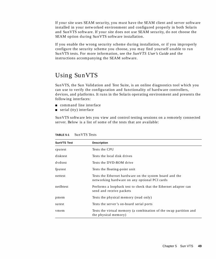
Using SunVTSSunVTS, the Sun Validation and Test Suite, is an online diagnostics tool which youcan use to verify the configuration and functionality of hardware controllers,devices, and platforms. It runs in the Solaris operating environment and presents thefollowing interfaces:
■ command line interface■ serial (tty) interface
SunVTS software lets you view and control testing sessions on a remotely connectedserver. Below is a list of some of the tests that are available:
TABLE 5-1 SunVTS Tests
SunVTS Test Description
cputest Tests the CPU
disktest Tests the local disk drives
dvdtest Tests the DVD-ROM drive
fputest Tests the floating-point unit
nettest Tests the Ethernet hardware on the system board and thenetworking hardware on any optional PCI cards
netlbtest Performs a loopback test to check that the Ethernet adapter cansend and receive packets
pmem Tests the physical memory (read only)
sutest Tests the server’s on-board serial ports
vmem Tests the virtual memory (a combination of the swap partition andthe physical memory)
Chapter 5 Sun VTS 49
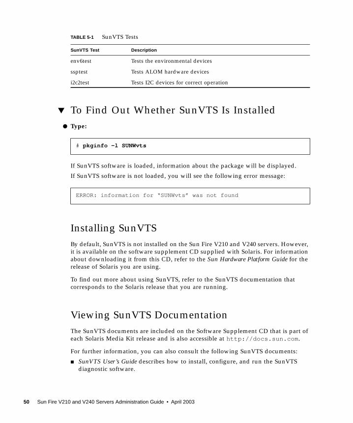
▼ To Find Out Whether SunVTS Is Installed● Type:
If SunVTS software is loaded, information about the package will be displayed.
If SunVTS software is not loaded, you will see the following error message:
Installing SunVTSBy default, SunVTS is not installed on the Sun Fire V210 and V240 servers. However,it is available on the software supplement CD supplied with Solaris. For informationabout downloading it from this CD, refer to the Sun Hardware Platform Guide for therelease of Solaris you are using.
To find out more about using SunVTS, refer to the SunVTS documentation thatcorresponds to the Solaris release that you are running.
Viewing SunVTS DocumentationThe SunVTS documents are included on the Software Supplement CD that is part ofeach Solaris Media Kit release and is also accessible at http://docs.sun.com.
For further information, you can also consult the following SunVTS documents:
■ SunVTS User’s Guide describes how to install, configure, and run the SunVTSdiagnostic software.
env6test Tests the environmental devices
ssptest Tests ALOM hardware devices
i2c2test Tests I2C devices for correct operation
# pkginfo -l SUNWvts
ERROR: information for “SUNWvts” was not found
TABLE 5-1 SunVTS Tests
SunVTS Test Description
50 Sun Fire V210 and V240 Servers Administration Guide • April 2003
■ SunVTS Quick Reference Card provides an overview of how to use the SunVTSCDE interface.
■ SunVTS Test Reference Manual provides details about each individual SunVTS test.
Chapter 5 Sun VTS 51

52 Sun Fire V210 and V240 Servers Administration Guide • April 2003
CHAPTER 6
Diagnostics
This chapter describes the diagnostics tools available to the Sun Fire V210 and V240servers. The chapter contains the sections:
■ “Overview Of Diagnostic Tools” on page 54
■ “Sun™ Advanced Lights-Out Manager” on page 55
■ “Status Indicators” on page 56
■ “POST Diagnostics” on page 56
■ “OpenBoot Diagnostics” on page 59
■ “OpenBoot Commands” on page 63
■ “Operating Environment Diagnostic Tools” on page 67
■ “Recent Diagnostic Test Results” on page 76
■ “OpenBoot Configuration Variables” on page 76
■ “Additional Diagnostic Tests for Specific Devices” on page 78
■ “Automatic Server Restart” on page 80
■ “Automatic System Recovery (ASR)” on page 81
53
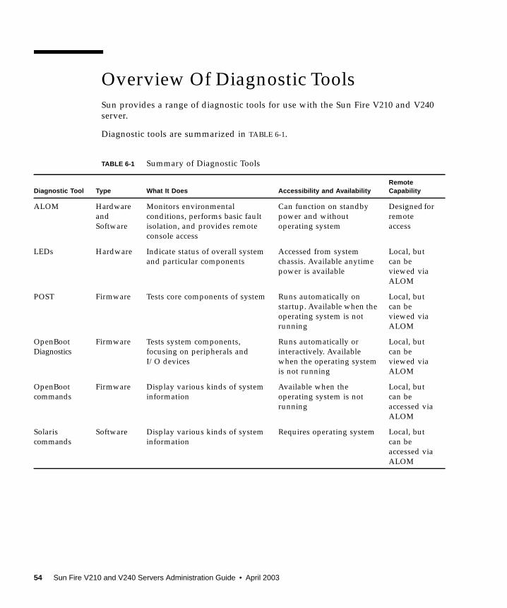
Overview Of Diagnostic ToolsSun provides a range of diagnostic tools for use with the Sun Fire V210 and V240server.
Diagnostic tools are summarized in TABLE 6-1.
TABLE 6-1 Summary of Diagnostic Tools
Diagnostic Tool Type What It Does Accessibility and AvailabilityRemoteCapability
ALOM HardwareandSoftware
Monitors environmentalconditions, performs basic faultisolation, and provides remoteconsole access
Can function on standbypower and withoutoperating system
Designed forremoteaccess
LEDs Hardware Indicate status of overall systemand particular components
Accessed from systemchassis. Available anytimepower is available
Local, butcan beviewed viaALOM
POST Firmware Tests core components of system Runs automatically onstartup. Available when theoperating system is notrunning
Local, butcan beviewed viaALOM
OpenBootDiagnostics
Firmware Tests system components,focusing on peripherals andI/O devices
Runs automatically orinteractively. Availablewhen the operating systemis not running
Local, butcan beviewed viaALOM
OpenBootcommands
Firmware Display various kinds of systeminformation
Available when theoperating system is notrunning
Local, butcan beaccessed viaALOM
Solariscommands
Software Display various kinds of systeminformation
Requires operating system Local, butcan beaccessed viaALOM
54 Sun Fire V210 and V240 Servers Administration Guide • April 2003
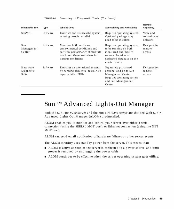
Sun™ Advanced Lights-Out ManagerBoth the Sun Fire V210 server and the Sun Fire V240 server are shipped with Sun™Advanced Lights Out Manager (ALOM) pre-installed.
ALOM enables you to monitor and control your server over either a serialconnection (using the SERIAL MGT port), or Ethernet connection (using the NETMGT port).
ALOM can send email notification of hardware failures or other server events.
The ALOM circuitry uses standby power from the server. This means that:
■ ALOM is active as soon as the server is connected to a power source, and untilpower is removed by unplugging the power cable.
■ ALOM continues to be effective when the server operating system goes offline.
SunVTS Software Exercises and stresses the system,running tests in parallel
Requires operating system.Optional package mayneed to be installed
View andcontrol overnetwork
SunManagementCenter
Software Monitors both hardwareenvironmental conditions andsoftware performance of multiplemachines. Generates alerts forvarious conditions
Requires operating systemto be running on bothmonitored and masterservers. Requires adedicated database on themaster server
Designed forremoteaccess
HardwareDiagnosticSuite
Software Exercises an operational systemby running sequential tests. Alsoreports failed FRUs
Separately purchasedoptional add-on to SunManagement Center.Requires operating systemand Sun ManagementCenter
Designed forremoteaccess
TABLE 6-1 Summary of Diagnostic Tools (Continued)
Diagnostic Tool Type What It Does Accessibility and AvailabilityRemoteCapability
Chapter 6 Diagnostics 55
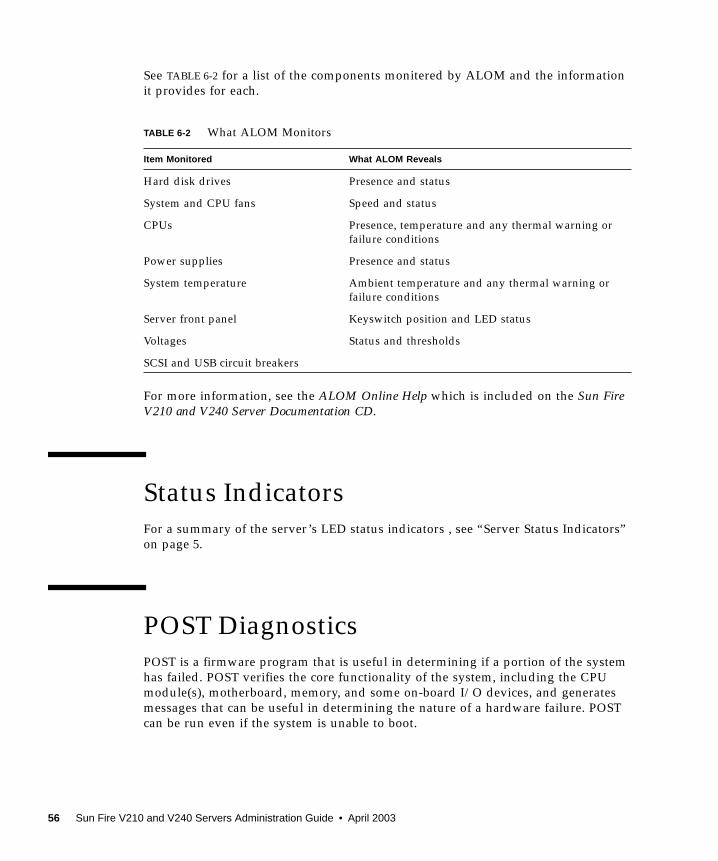
See TABLE 6-2 for a list of the components monitered by ALOM and the informationit provides for each.
For more information, see the ALOM Online Help which is included on the Sun FireV210 and V240 Server Documentation CD.
Status IndicatorsFor a summary of the server’s LED status indicators , see “Server Status Indicators”on page 5.
POST DiagnosticsPOST is a firmware program that is useful in determining if a portion of the systemhas failed. POST verifies the core functionality of the system, including the CPUmodule(s), motherboard, memory, and some on-board I/O devices, and generatesmessages that can be useful in determining the nature of a hardware failure. POSTcan be run even if the system is unable to boot.
TABLE 6-2 What ALOM Monitors
Item Monitored What ALOM Reveals
Hard disk drives Presence and status
System and CPU fans Speed and status
CPUs Presence, temperature and any thermal warning orfailure conditions
Power supplies Presence and status
System temperature Ambient temperature and any thermal warning orfailure conditions
Server front panel Keyswitch position and LED status
Voltages Status and thresholds
SCSI and USB circuit breakers
56 Sun Fire V210 and V240 Servers Administration Guide • April 2003
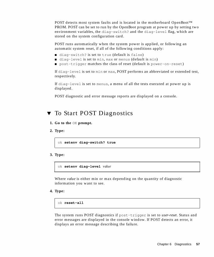
POST detects most system faults and is located in the motherboard OpenBoot™PROM. POST can be set to run by the OpenBoot program at power up by setting twoenvironment variables, the diag-switch? and the diag-level flag, which arestored on the system configuration card.
POST runs automatically when the system power is applied, or following anautomatic system reset, if all of the following conditions apply:
■ diag-switch? is set to true (default is false)■ diag-level is set to min, max or menus (default is min)■ post-trigger matches the class of reset (default is power-on-reset)
If diag-level is set to min or max, POST performs an abbreviated or extended test,respectively.
If diag-level is set to menus, a menu of all the tests executed at power up isdisplayed.
POST diagnostic and error message reports are displayed on a console.
▼ To Start POST Diagnostics1. Go to the OK prompt.
2. Type:
3. Type:
Where value is either min or max depending on the quantity of diagnosticinformation you want to see.
4. Type:
The system runs POST diagnostics if post-trigger is set to user-reset. Status anderror messages are displayed in the console window. If POST detects an error, itdisplays an error message describing the failure.
ok setenv diag-switch? true
ok setenv diag-level value
ok reset-all
Chapter 6 Diagnostics 57
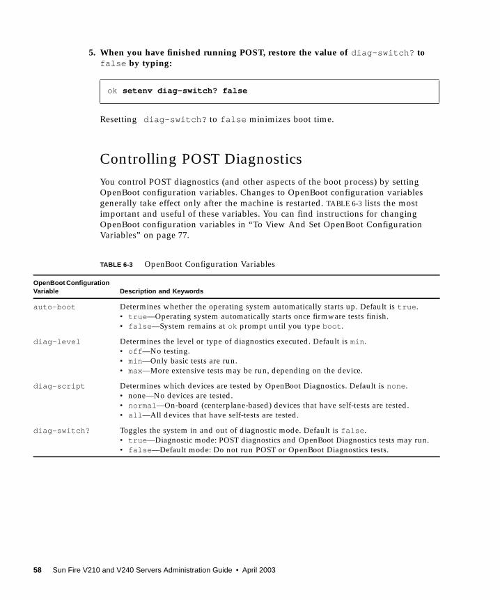
5. When you have finished running POST, restore the value of diag-switch? tofalse by typing:
Resetting diag-switch? to false minimizes boot time.
Controlling POST DiagnosticsYou control POST diagnostics (and other aspects of the boot process) by settingOpenBoot configuration variables. Changes to OpenBoot configuration variablesgenerally take effect only after the machine is restarted. TABLE 6-3 lists the mostimportant and useful of these variables. You can find instructions for changingOpenBoot configuration variables in “To View And Set OpenBoot ConfigurationVariables” on page 77.
ok setenv diag-switch? false
TABLE 6-3 OpenBoot Configuration Variables
OpenBoot ConfigurationVariable Description and Keywords
auto-boot Determines whether the operating system automatically starts up. Default is true.• true—Operating system automatically starts once firmware tests finish.• false—System remains at ok prompt until you type boot.
diag-level Determines the level or type of diagnostics executed. Default is min.• off—No testing.• min—Only basic tests are run.• max—More extensive tests may be run, depending on the device.
diag-script Determines which devices are tested by OpenBoot Diagnostics. Default is none.• none—No devices are tested.• normal—On-board (centerplane-based) devices that have self-tests are tested.• all—All devices that have self-tests are tested.
diag-switch? Toggles the system in and out of diagnostic mode. Default is false.• true—Diagnostic mode: POST diagnostics and OpenBoot Diagnostics tests may run.• false—Default mode: Do not run POST or OpenBoot Diagnostics tests.
58 Sun Fire V210 and V240 Servers Administration Guide • April 2003
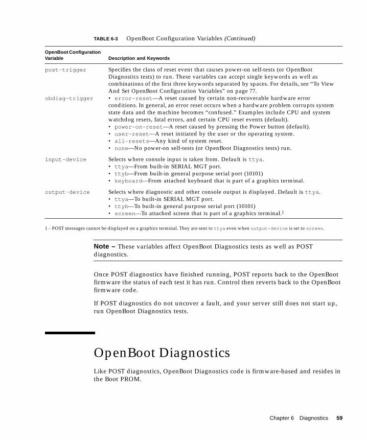
1 – POST messages cannot be displayed on a graphics terminal. They are sent to ttya even when output-device is set to screen.
Note – These variables affect OpenBoot Diagnostics tests as well as POSTdiagnostics.
Once POST diagnostics have finished running, POST reports back to the OpenBootfirmware the status of each test it has run. Control then reverts back to the OpenBootfirmware code.
If POST diagnostics do not uncover a fault, and your server still does not start up,run OpenBoot Diagnostics tests.
OpenBoot DiagnosticsLike POST diagnostics, OpenBoot Diagnostics code is firmware-based and resides inthe Boot PROM.
post-trigger
obdiag-trigger
Specifies the class of reset event that causes power-on self-tests (or OpenBootDiagnostics tests) to run. These variables can accept single keywords as well ascombinations of the first three keywords separated by spaces. For details, see “To ViewAnd Set OpenBoot Configuration Variables” on page 77.• error-reset—A reset caused by certain non-recoverable hardware errorconditions. In general, an error reset occurs when a hardware problem corrupts systemstate data and the machine becomes “confused.” Examples include CPU and systemwatchdog resets, fatal errors, and certain CPU reset events (default).• power-on-reset—A reset caused by pressing the Power button (default).• user-reset—A reset initiated by the user or the operating system.• all-resets—Any kind of system reset.• none—No power-on self-tests (or OpenBoot Diagnostics tests) run.
input-device Selects where console input is taken from. Default is ttya.• ttya—From built-in SERIAL MGT port.• ttyb—From built-in general purpose serial port (10101)• keyboard—From attached keyboard that is part of a graphics terminal.
output-device Selects where diagnostic and other console output is displayed. Default is ttya.• ttya—To built-in SERIAL MGT port.• ttyb—To built-in general purpose serial port (10101)• screen—To attached screen that is part of a graphics terminal.1
TABLE 6-3 OpenBoot Configuration Variables (Continued)
OpenBoot ConfigurationVariable Description and Keywords
Chapter 6 Diagnostics 59
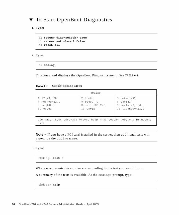
▼ To Start OpenBoot Diagnostics1. Type:
2. Type:
This command displays the OpenBoot Diagnostics menu. See TABLE 6-4.
Note – If you have a PCI card installed in the server, then additional tests willappear on the obdiag menu.
3. Type:
Where n represents the number corresponding to the test you want to run.
A summary of the tests is available. At the obdiag> prompt, type:
ok setenv diag-switch? trueok setenv auto-boot? falseok reset-all
ok obdiag
TABLE 6-4 Sample obdiag Menu
obdiag
1 i2c@0,3204 network@2,17 scsi@2,110 usb@a
2 ide@d5 rtc@0,708 serial@0,2e811 usb@b
3 network@26 scsi@29 serial@0,3f812 flashprom@2,0
Commands: test test-all except help what setenv versions printenvsexit
obdiag> test n
obdiag> help
60 Sun Fire V210 and V240 Servers Administration Guide • April 2003
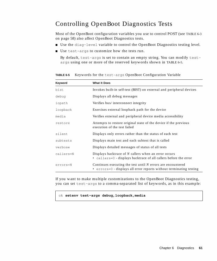
Controlling OpenBoot Diagnostics TestsMost of the OpenBoot configuration variables you use to control POST (see TABLE 6-3on page 58) also affect OpenBoot Diagnostics tests.
■ Use the diag-level variable to control the OpenBoot Diagnostics testing level.
■ Use test-args to customize how the tests run.
By default, test-args is set to contain an empty string. You can modify test-args using one or more of the reserved keywords shown in TABLE 6-5.
If you want to make multiple customizations to the OpenBoot Diagnostics testing,you can set test-args to a comma-separated list of keywords, as in this example:
TABLE 6-5 Keywords for the test-args OpenBoot Configuration Variable
Keyword What It Does
bist Invokes built-in self-test (BIST) on external and peripheral devices
debug Displays all debug messages
iopath Verifies bus/interconnect integrity
loopback Exercises external loopback path for the device
media Verifies external and peripheral device media accessibility
restore Attempts to restore original state of the device if the previousexecution of the test failed
silent Displays only errors rather than the status of each test
subtests Displays main test and each subtest that is called
verbose Displays detailed messages of status of all tests
callers=N Displays backtrace of N callers when an error occurs• callers=0 - displays backtrace of all callers before the error
errors=N Continues executing the test until N errors are encountered• errors=0 - displays all error reports without terminating testing
ok setenv test-args debug,loopback,media
Chapter 6 Diagnostics 61
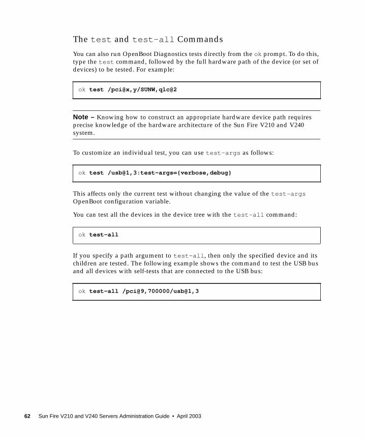
The test and test-all Commands
You can also run OpenBoot Diagnostics tests directly from the ok prompt. To do this,type the test command, followed by the full hardware path of the device (or set ofdevices) to be tested. For example:
Note – Knowing how to construct an appropriate hardware device path requiresprecise knowledge of the hardware architecture of the Sun Fire V210 and V240system.
To customize an individual test, you can use test-args as follows:
This affects only the current test without changing the value of the test-argsOpenBoot configuration variable.
You can test all the devices in the device tree with the test-all command:
If you specify a path argument to test-all, then only the specified device and itschildren are tested. The following example shows the command to test the USB busand all devices with self-tests that are connected to the USB bus:
ok test /pci@x,y/SUNW,qlc@2
ok test /usb@1,3:test-args={verbose,debug}
ok test-all
ok test-all /pci@9,700000/usb@1,3
62 Sun Fire V210 and V240 Servers Administration Guide • April 2003
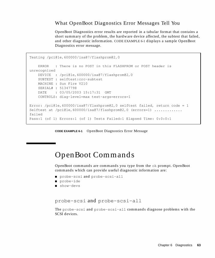
What OpenBoot Diagnostics Error Messages Tell You
OpenBoot Diagnostics error results are reported in a tabular format that contains ashort summary of the problem, the hardware device affected, the subtest that failed,and other diagnostic information. CODE EXAMPLE 6-1 displays a sample OpenBootDiagnostics error message.
CODE EXAMPLE 6-1 OpenBoot Diagnostics Error Message
OpenBoot CommandsOpenBoot commands are commands you type from the ok prompt. OpenBootcommands which can provide useful diagnostic information are:
■ probe-scsi and probe-scsi-all■ probe-ide■ show-devs
probe-scsi and probe-scsi-all
The probe-scsi and probe-scsi-all commands diagnose problems with theSCSI devices.
Testing /pci@1e,600000/isa@7/flashprom@2,0
ERROR : There is no POST in this FLASHPROM or POST header isunrecognized DEVICE : /pci@1e,600000/isa@7/flashprom@2,0 SUBTEST : selftest:crc-subtest MACHINE : Sun Fire V210 SERIAL# : 51347798 DATE : 03/05/2003 15:17:31 GMT CONTR0LS: diag-level=max test-args=errors=1
Error: /pci@1e,600000/isa@7/flashprom@2,0 selftest failed, return code = 1Selftest at /pci@1e,600000/isa@7/flashprom@2,0 (errors=1) .............failedPass:1 (of 1) Errors:1 (of 1) Tests Failed:1 Elapsed Time: 0:0:0:1
Chapter 6 Diagnostics 63
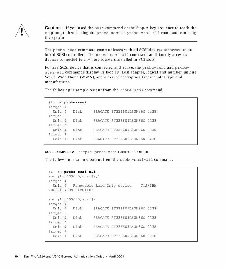
Caution – If you used the halt command or the Stop-A key sequence to reach theok prompt, then issuing the probe-scsi or probe-scsi-all command can hangthe system.
The probe-scsi command communicates with all SCSI devices connected to on-board SCSI controllers. The probe-scsi-all command additionally accessesdevices connected to any host adapters installed in PCI slots.
For any SCSI device that is connected and active, the probe-scsi and probe-scsi-all commands display its loop ID, host adapter, logical unit number, uniqueWorld Wide Name (WWN), and a device description that includes type andmanufacturer.
The following is sample output from the probe-scsi command.
CODE EXAMPLE 6-2 sample probe-scsi Command Output
The following is sample output from the probe-scsi-all command.
{1} ok probe-scsiTarget 0 Unit 0 Disk SEAGATE ST336605LSUN36G 0238Target 1 Unit 0 Disk SEAGATE ST336605LSUN36G 0238Target 2 Unit 0 Disk SEAGATE ST336605LSUN36G 0238Target 3 Unit 0 Disk SEAGATE ST336605LSUN36G 0238
{1} ok probe-scsi-all/pci@1c,600000/scsi@2,1Target 4 Unit 0 Removable Read Only device TOSHIBAXM6201TASUN32XCD1103
/pci@1c,600000/scsi@2Target 0 Unit 0 Disk SEAGATE ST336605LSUN36G 0238Target 1 Unit 0 Disk SEAGATE ST336605LSUN36G 0238Target 2 Unit 0 Disk SEAGATE ST336605LSUN36G 0238Target 3 Unit 0 Disk SEAGATE ST336605LSUN36G 0238
64 Sun Fire V210 and V240 Servers Administration Guide • April 2003
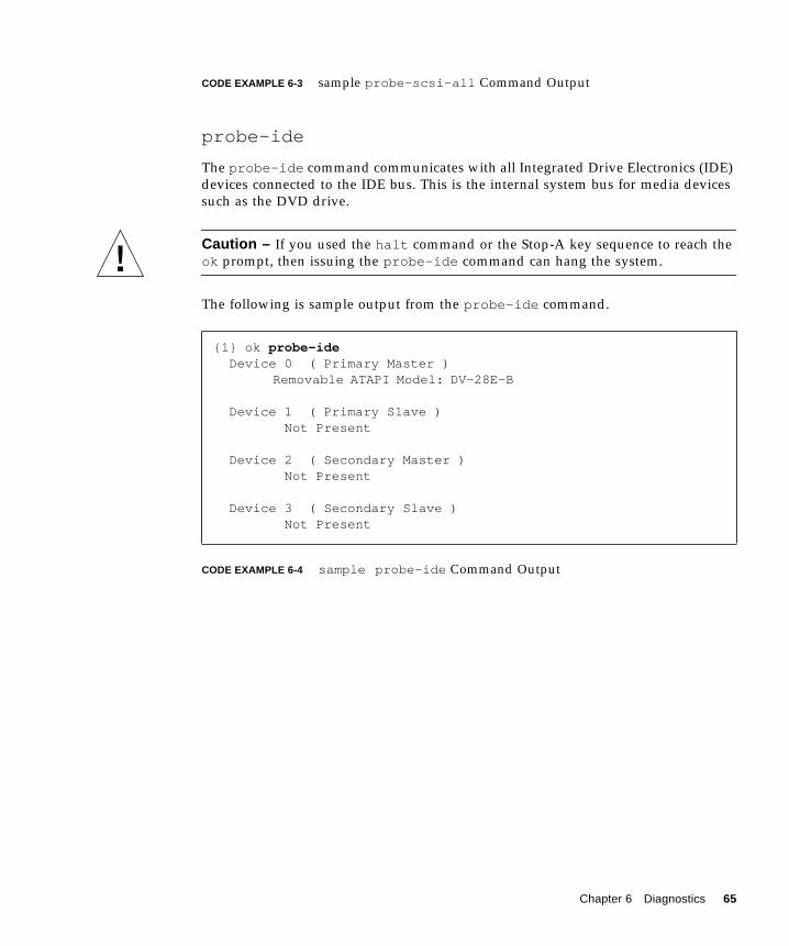
CODE EXAMPLE 6-3 sample probe-scsi-all Command Output
probe-ide
The probe-ide command communicates with all Integrated Drive Electronics (IDE)devices connected to the IDE bus. This is the internal system bus for media devicessuch as the DVD drive.
Caution – If you used the halt command or the Stop-A key sequence to reach theok prompt, then issuing the probe-ide command can hang the system.
The following is sample output from the probe-ide command.
CODE EXAMPLE 6-4 sample probe-ide Command Output
{1} ok probe-ide Device 0 ( Primary Master )
Removable ATAPI Model: DV-28E-B
Device 1 ( Primary Slave ) Not Present
Device 2 ( Secondary Master ) Not Present
Device 3 ( Secondary Slave ) Not Present
Chapter 6 Diagnostics 65
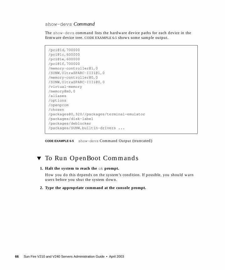
show-devs Command
The show-devs command lists the hardware device paths for each device in thefirmware device tree. CODE EXAMPLE 6-5 shows some sample output.
CODE EXAMPLE 6-5 show-devs Command Output (truncated)
▼ To Run OpenBoot Commands1. Halt the system to reach the ok prompt.
How you do this depends on the system’s condition. If possible, you should warnusers before you shut the system down.
2. Type the appropriate command at the console prompt.
/pci@1d,700000/pci@1c,600000/pci@1e,600000/pci@1f,700000/memory-controller@1,0/SUNW,UltraSPARC-IIIi@1,0/memory-controller@0,0/SUNW,UltraSPARC-IIIi@0,0/virtual-memory/memory@m0,0/aliases/options/openprom/chosen/packages@0,320//packages/terminal-emulator/packages/disk-label/packages/deblocker/packages/SUNW,builtin-drivers ...
66 Sun Fire V210 and V240 Servers Administration Guide • April 2003
Operating Environment DiagnosticToolsIf a system passes OpenBoot Diagnostics tests, it normally attempts to boot itsmultiuser operating environment. For most Sun systems, this means the Solarisoperating environment. Once the server is running in multiuser mode, you haveaccess to the software-based diagnostic tools, SunVTS and Sun Management Center.These tools allow you to monitor the server, exercise it, and isolate faults.
Note – If you set the auto-boot OpenBoot configuration variable to false, theoperating system does not boot following completion of the firmware-based tests.
In addition to the tools mentioned above, you can refer to error and system messagelog files, and Solaris system information commands.
Error and System Message Log FilesError and other system messages are saved in the /var/adm/messages file.Messages are logged to this file from many sources, including the operating system,the environmental control subsystem, and various software applications.
Solaris System Information CommandsThe following Solaris commands display data that you can use when assessing thecondition of a Sun Fire V210 and V240 server:
■ prtconf■ prtdiag■ prtfru■ psrinfo■ showrev
This section describes the information these commands give you. More informationon using these commands is contained in the appropriate man page.
Chapter 6 Diagnostics 67
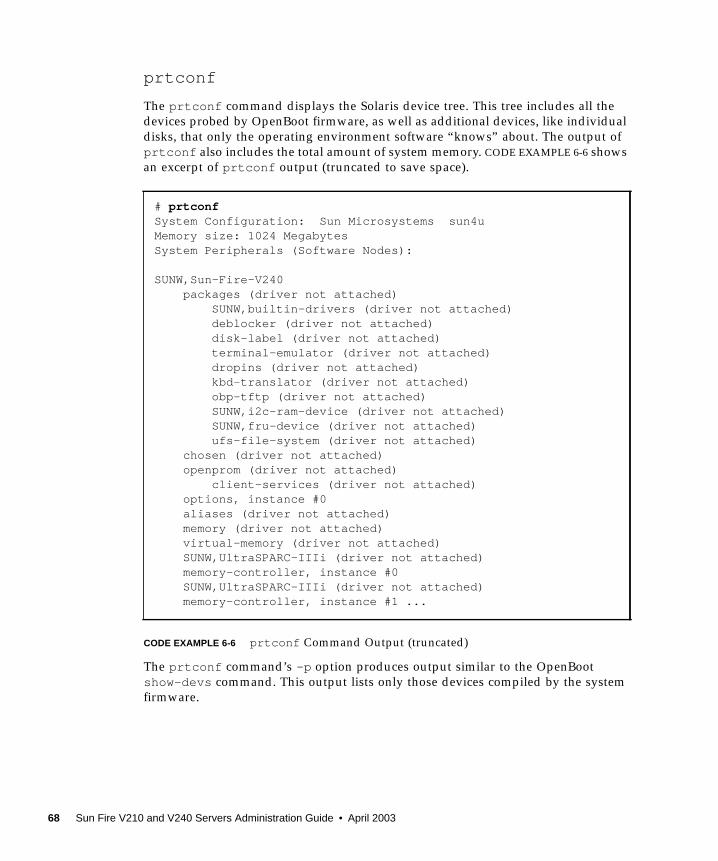
prtconf
The prtconf command displays the Solaris device tree. This tree includes all thedevices probed by OpenBoot firmware, as well as additional devices, like individualdisks, that only the operating environment software “knows” about. The output ofprtconf also includes the total amount of system memory. CODE EXAMPLE 6-6 showsan excerpt of prtconf output (truncated to save space).
CODE EXAMPLE 6-6 prtconf Command Output (truncated)
The prtconf command’s -p option produces output similar to the OpenBootshow-devs command. This output lists only those devices compiled by the systemfirmware.
# prtconfSystem Configuration: Sun Microsystems sun4uMemory size: 1024 MegabytesSystem Peripherals (Software Nodes):
SUNW,Sun-Fire-V240 packages (driver not attached) SUNW,builtin-drivers (driver not attached) deblocker (driver not attached) disk-label (driver not attached) terminal-emulator (driver not attached) dropins (driver not attached) kbd-translator (driver not attached) obp-tftp (driver not attached) SUNW,i2c-ram-device (driver not attached) SUNW,fru-device (driver not attached) ufs-file-system (driver not attached) chosen (driver not attached) openprom (driver not attached) client-services (driver not attached) options, instance #0 aliases (driver not attached) memory (driver not attached) virtual-memory (driver not attached) SUNW,UltraSPARC-IIIi (driver not attached) memory-controller, instance #0 SUNW,UltraSPARC-IIIi (driver not attached) memory-controller, instance #1 ...
68 Sun Fire V210 and V240 Servers Administration Guide • April 2003

prtdiag
The prtdiag command displays a table of diagnostic information that summarizesthe status of system components.
Chapter 6 Diagnostics 69

The display format used by the prtdiag command can vary depending on whatversion of the Solaris operating environment is running on your system. Followingis an excerpt of some of the output produced by prtdiag on a healthy Sun Fire
70 Sun Fire V210 and V240 Servers Administration Guide • April 2003
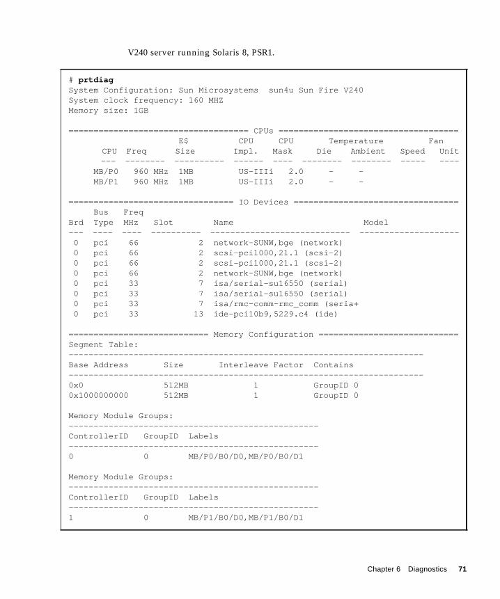
V240 server running Solaris 8, PSR1.
# prtdiagSystem Configuration: Sun Microsystems sun4u Sun Fire V240System clock frequency: 160 MHZMemory size: 1GB
==================================== CPUs ==================================== E$ CPU CPU Temperature Fan
CPU Freq Size Impl. Mask Die Ambient Speed Unit--- -------- ---------- ------ ---- -------- -------- ----- ----
MB/P0 960 MHz 1MB US-IIIi 2.0 - - MB/P1 960 MHz 1MB US-IIIi 2.0 - -
================================= IO Devices ================================= Bus FreqBrd Type MHz Slot Name Model--- ---- ---- ---------- ---------------------------- -------------------- 0 pci 66 2 network-SUNW,bge (network) 0 pci 66 2 scsi-pci1000,21.1 (scsi-2) 0 pci 66 2 scsi-pci1000,21.1 (scsi-2) 0 pci 66 2 network-SUNW,bge (network) 0 pci 33 7 isa/serial-su16550 (serial) 0 pci 33 7 isa/serial-su16550 (serial) 0 pci 33 7 isa/rmc-comm-rmc_comm (seria+ 0 pci 33 13 ide-pci10b9,5229.c4 (ide)
============================ Memory Configuration ============================Segment Table:-----------------------------------------------------------------------Base Address Size Interleave Factor Contains-----------------------------------------------------------------------0x0 512MB 1 GroupID 00x1000000000 512MB 1 GroupID 0
Memory Module Groups:--------------------------------------------------ControllerID GroupID Labels--------------------------------------------------0 0 MB/P0/B0/D0,MB/P0/B0/D1
Memory Module Groups:--------------------------------------------------ControllerID GroupID Labels--------------------------------------------------1 0 MB/P1/B0/D0,MB/P1/B0/D1
Chapter 6 Diagnostics 71
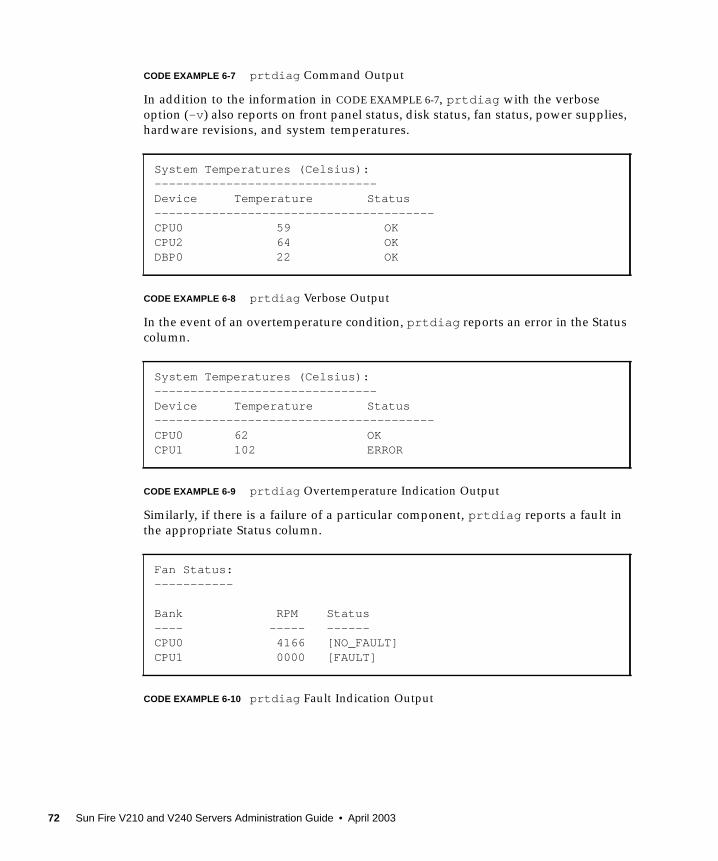
CODE EXAMPLE 6-7 prtdiag Command Output
In addition to the information in CODE EXAMPLE 6-7, prtdiag with the verboseoption (-v) also reports on front panel status, disk status, fan status, power supplies,hardware revisions, and system temperatures.
CODE EXAMPLE 6-8 prtdiag Verbose Output
In the event of an overtemperature condition, prtdiag reports an error in the Statuscolumn.
CODE EXAMPLE 6-9 prtdiag Overtemperature Indication Output
Similarly, if there is a failure of a particular component, prtdiag reports a fault inthe appropriate Status column.
CODE EXAMPLE 6-10 prtdiag Fault Indication Output
System Temperatures (Celsius):-------------------------------Device Temperature Status---------------------------------------CPU0 59 OKCPU2 64 OKDBP0 22 OK
System Temperatures (Celsius):-------------------------------Device Temperature Status---------------------------------------CPU0 62 OKCPU1 102 ERROR
Fan Status:-----------
Bank RPM Status---- ----- ------CPU0 4166 [NO_FAULT]CPU1 0000 [FAULT]
72 Sun Fire V210 and V240 Servers Administration Guide • April 2003
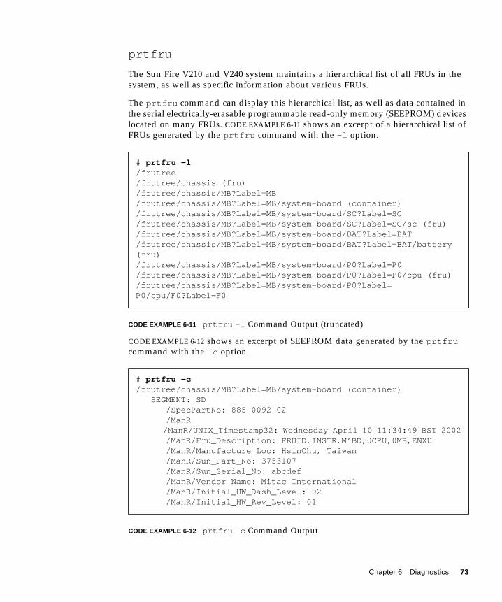
prtfru
The Sun Fire V210 and V240 system maintains a hierarchical list of all FRUs in thesystem, as well as specific information about various FRUs.
The prtfru command can display this hierarchical list, as well as data contained inthe serial electrically-erasable programmable read-only memory (SEEPROM) deviceslocated on many FRUs. CODE EXAMPLE 6-11 shows an excerpt of a hierarchical list ofFRUs generated by the prtfru command with the -l option.
CODE EXAMPLE 6-11 prtfru -l Command Output (truncated)
CODE EXAMPLE 6-12 shows an excerpt of SEEPROM data generated by the prtfrucommand with the -c option.
CODE EXAMPLE 6-12 prtfru -c Command Output
# prtfru -l/frutree/frutree/chassis (fru)/frutree/chassis/MB?Label=MB/frutree/chassis/MB?Label=MB/system-board (container)/frutree/chassis/MB?Label=MB/system-board/SC?Label=SC/frutree/chassis/MB?Label=MB/system-board/SC?Label=SC/sc (fru)/frutree/chassis/MB?Label=MB/system-board/BAT?Label=BAT/frutree/chassis/MB?Label=MB/system-board/BAT?Label=BAT/battery(fru)/frutree/chassis/MB?Label=MB/system-board/P0?Label=P0/frutree/chassis/MB?Label=MB/system-board/P0?Label=P0/cpu (fru)/frutree/chassis/MB?Label=MB/system-board/P0?Label=P0/cpu/F0?Label=F0
# prtfru -c/frutree/chassis/MB?Label=MB/system-board (container) SEGMENT: SD /SpecPartNo: 885-0092-02 /ManR
/ManR/UNIX_Timestamp32: Wednesday April 10 11:34:49 BST 2002 /ManR/Fru_Description: FRUID,INSTR,M’BD,0CPU,0MB,ENXU /ManR/Manufacture_Loc: HsinChu, Taiwan /ManR/Sun_Part_No: 3753107 /ManR/Sun_Serial_No: abcdef /ManR/Vendor_Name: Mitac International /ManR/Initial_HW_Dash_Level: 02 /ManR/Initial_HW_Rev_Level: 01
Chapter 6 Diagnostics 73
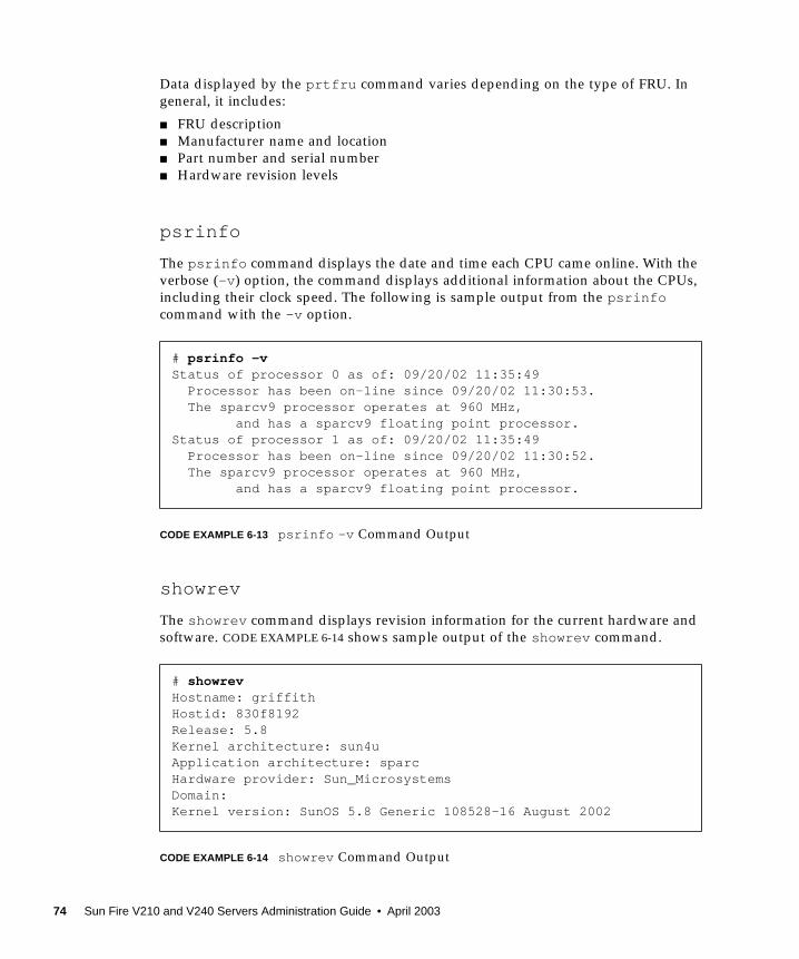
Data displayed by the prtfru command varies depending on the type of FRU. Ingeneral, it includes:
■ FRU description■ Manufacturer name and location■ Part number and serial number■ Hardware revision levels
psrinfo
The psrinfo command displays the date and time each CPU came online. With theverbose (-v) option, the command displays additional information about the CPUs,including their clock speed. The following is sample output from the psrinfocommand with the -v option.
CODE EXAMPLE 6-13 psrinfo -v Command Output
showrev
The showrev command displays revision information for the current hardware andsoftware. CODE EXAMPLE 6-14 shows sample output of the showrev command.
CODE EXAMPLE 6-14 showrev Command Output
# psrinfo -vStatus of processor 0 as of: 09/20/02 11:35:49 Processor has been on-line since 09/20/02 11:30:53. The sparcv9 processor operates at 960 MHz, and has a sparcv9 floating point processor.Status of processor 1 as of: 09/20/02 11:35:49 Processor has been on-line since 09/20/02 11:30:52. The sparcv9 processor operates at 960 MHz, and has a sparcv9 floating point processor.
# showrevHostname: griffithHostid: 830f8192Release: 5.8Kernel architecture: sun4uApplication architecture: sparcHardware provider: Sun_MicrosystemsDomain:Kernel version: SunOS 5.8 Generic 108528-16 August 2002
74 Sun Fire V210 and V240 Servers Administration Guide • April 2003
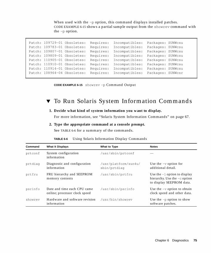
When used with the -p option, this command displays installed patches.CODE EXAMPLE 6-15 shows a partial sample output from the showrev command withthe -p option.
CODE EXAMPLE 6-15 showrev -p Command Output
▼ To Run Solaris System Information Commands1. Decide what kind of system information you want to display.
For more information, see “Solaris System Information Commands” on page 67.
2. Type the appropriate command at a console prompt.
See TABLE 6-6 for a summary of the commands.
Patch: 109729-01 Obsoletes: Requires: Incompatibles: Packages: SUNWcsuPatch: 109783-01 Obsoletes: Requires: Incompatibles: Packages: SUNWcsuPatch: 109807-01 Obsoletes: Requires: Incompatibles: Packages: SUNWcsuPatch: 109809-01 Obsoletes: Requires: Incompatibles: Packages: SUNWcsuPatch: 110905-01 Obsoletes: Requires: Incompatibles: Packages: SUNWcsuPatch: 110910-01 Obsoletes: Requires: Incompatibles: Packages: SUNWcsuPatch: 110914-01 Obsoletes: Requires: Incompatibles: Packages: SUNWcsuPatch: 108964-04 Obsoletes: Requires: Incompatibles: Packages: SUNWcsr
TABLE 6-6 Using Solaris Information Display Commands
Command What It Displays What to Type Notes
prtconf System configurationinformation
/usr/sbin/prtconf —
prtdiag Diagnostic and configurationinformation
/usr/platform/sun4u/sbin/prtdiag
Use the -v option foradditional detail.
prtfru FRU hierarchy and SEEPROMmemory contents
/usr/sbin/prtfru Use the -l option to displayhierarchy. Use the -c optionto display SEEPROM data.
psrinfo Date and time each CPU cameonline; processor clock speed
/usr/sbin/psrinfo Use the -v option to obtainclock speed and other data.
showrev Hardware and software revisioninformation
/usr/bin/showrev Use the -p option to showsoftware patches.
Chapter 6 Diagnostics 75
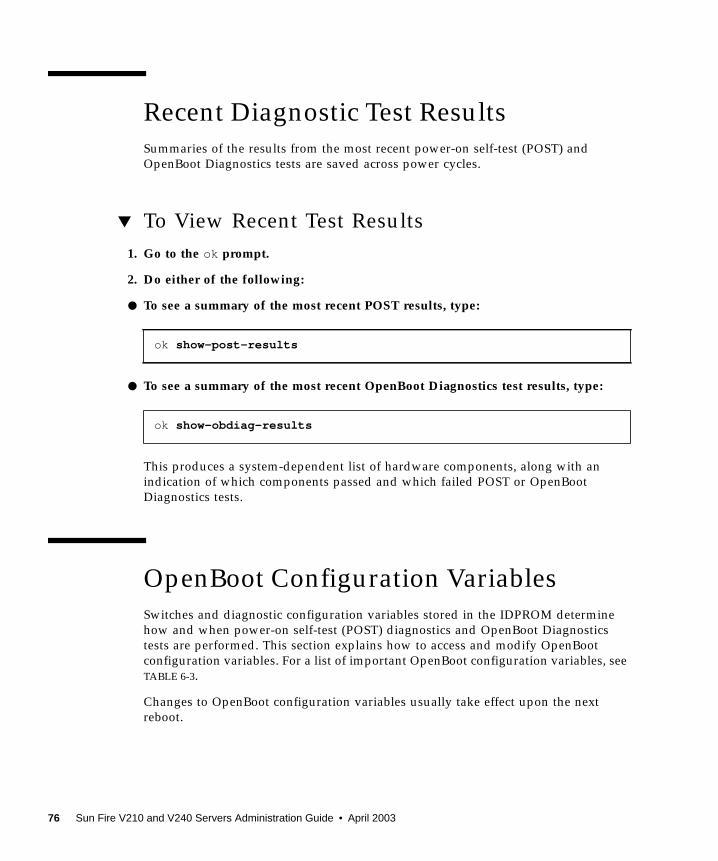
Recent Diagnostic Test ResultsSummaries of the results from the most recent power-on self-test (POST) andOpenBoot Diagnostics tests are saved across power cycles.
▼ To View Recent Test Results1. Go to the ok prompt.
2. Do either of the following:
● To see a summary of the most recent POST results, type:
● To see a summary of the most recent OpenBoot Diagnostics test results, type:
This produces a system-dependent list of hardware components, along with anindication of which components passed and which failed POST or OpenBootDiagnostics tests.
OpenBoot Configuration VariablesSwitches and diagnostic configuration variables stored in the IDPROM determinehow and when power-on self-test (POST) diagnostics and OpenBoot Diagnosticstests are performed. This section explains how to access and modify OpenBootconfiguration variables. For a list of important OpenBoot configuration variables, seeTABLE 6-3.
Changes to OpenBoot configuration variables usually take effect upon the nextreboot.
ok show-post-results
ok show-obdiag-results
76 Sun Fire V210 and V240 Servers Administration Guide • April 2003
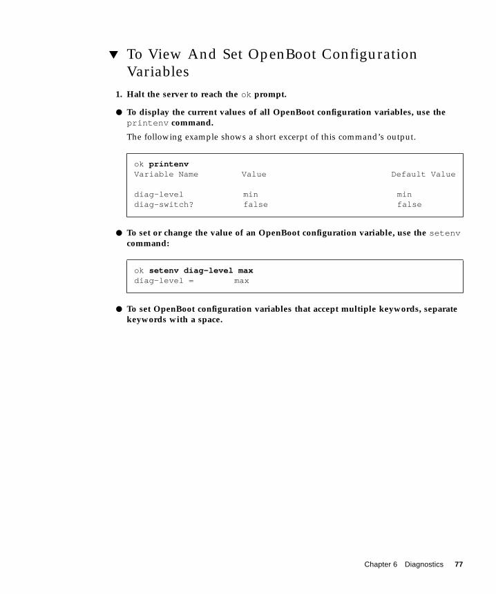
▼ To View And Set OpenBoot ConfigurationVariables
1. Halt the server to reach the ok prompt.
● To display the current values of all OpenBoot configuration variables, use theprintenv command.
The following example shows a short excerpt of this command’s output.
● To set or change the value of an OpenBoot configuration variable, use the setenvcommand:
● To set OpenBoot configuration variables that accept multiple keywords, separatekeywords with a space.
ok printenvVariable Name Value Default Value
diag-level min mindiag-switch? false false
ok setenv diag-level maxdiag-level = max
Chapter 6 Diagnostics 77
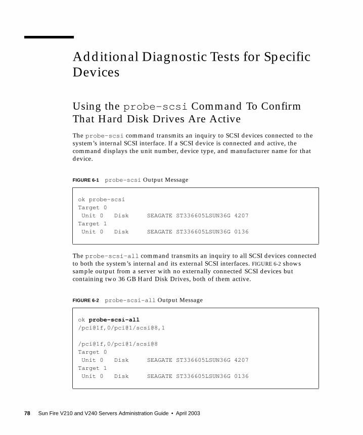
Additional Diagnostic Tests for SpecificDevices
Using the probe-scsi Command To ConfirmThat Hard Disk Drives Are ActiveThe probe-scsi command transmits an inquiry to SCSI devices connected to thesystem’s internal SCSI interface. If a SCSI device is connected and active, thecommand displays the unit number, device type, and manufacturer name for thatdevice.
The probe-scsi-all command transmits an inquiry to all SCSI devices connectedto both the system’s internal and its external SCSI interfaces. FIGURE 6-2 showssample output from a server with no externally connected SCSI devices butcontaining two 36 GB Hard Disk Drives, both of them active.
FIGURE 6-1 probe-scsi Output Message
ok probe-scsi
Target 0
Unit 0 Disk SEAGATE ST336605LSUN36G 4207
Target 1
Unit 0 Disk SEAGATE ST336605LSUN36G 0136
FIGURE 6-2 probe-scsi-all Output Message
ok probe-scsi-all
/pci@1f,0/pci@1/scsi@8,1
/pci@1f,0/pci@1/scsi@8
Target 0
Unit 0 Disk SEAGATE ST336605LSUN36G 4207
Target 1
Unit 0 Disk SEAGATE ST336605LSUN36G 0136
78 Sun Fire V210 and V240 Servers Administration Guide • April 2003
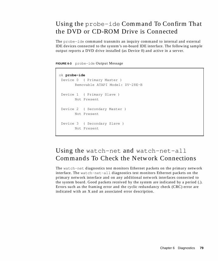
Using the probe-ide Command To Confirm Thatthe DVD or CD-ROM Drive is ConnectedThe probe-ide command transmits an inquiry command to internal and externalIDE devices connected to the system’s on-board IDE interface. The following sampleoutput reports a DVD drive installed (as Device 0) and active in a server.
Using the watch-net and watch-net-allCommands To Check the Network ConnectionsThe watch-net diagnostics test monitors Ethernet packets on the primary networkinterface. The watch-net-all diagnostics test monitors Ethernet packets on theprimary network interface and on any additional network interfaces connected tothe system board. Good packets received by the system are indicated by a period (.).Errors such as the framing error and the cyclic redundancy check (CRC) error areindicated with an X and an associated error description.
FIGURE 6-3 probe-ide Output Message
ok probe-ide
Device 0 ( Primary Master )
Removable ATAPI Model: DV-28E-B
Device 1 ( Primary Slave )
Not Present
Device 2 ( Secondary Master )
Not Present
Device 3 ( Secondary Slave )
Not Present
Chapter 6 Diagnostics 79
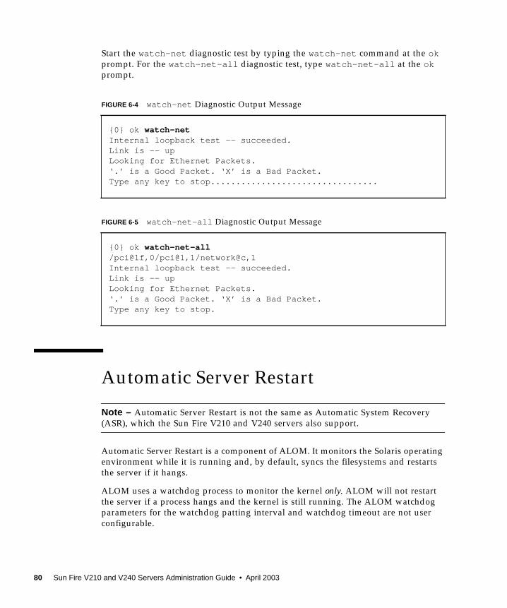
Start the watch-net diagnostic test by typing the watch-net command at the okprompt. For the watch-net-all diagnostic test, type watch-net-all at the okprompt.
Automatic Server Restart
Note – Automatic Server Restart is not the same as Automatic System Recovery(ASR), which the Sun Fire V210 and V240 servers also support.
Automatic Server Restart is a component of ALOM. It monitors the Solaris operatingenvironment while it is running and, by default, syncs the filesystems and restartsthe server if it hangs.
ALOM uses a watchdog process to monitor the kernel only. ALOM will not restartthe server if a process hangs and the kernel is still running. The ALOM watchdogparameters for the watchdog patting interval and watchdog timeout are not userconfigurable.
FIGURE 6-4 watch-net Diagnostic Output Message
{0} ok watch-netInternal loopback test -- succeeded.Link is -- upLooking for Ethernet Packets.‘.’ is a Good Packet. ‘X’ is a Bad Packet.Type any key to stop.................................
FIGURE 6-5 watch-net-all Diagnostic Output Message
{0} ok watch-net-all/pci@1f,0/pci@1,1/network@c,1Internal loopback test -- succeeded.Link is -- upLooking for Ethernet Packets.‘.’ is a Good Packet. ‘X’ is a Bad Packet.Type any key to stop.
80 Sun Fire V210 and V240 Servers Administration Guide • April 2003
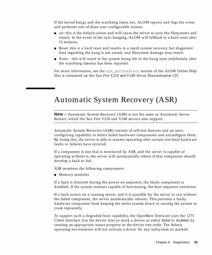
If the kernel hangs and the watchdog times out, ALOM reports and logs the eventand performs one of three user configurable actions.
■ xir: this is the default action and will cause the server to sync the filesystems andrestart. In the event of the sync hanging, ALOM will fallback to a hard reset after15 minutes.
■ Reset: this is a hard reset and results in a rapid system recovery but diagnosticdata regarding the hang is not stored, and filesystem damage may result.
■ None - this will result in the system being left in the hung state indefinitely afterthe watchdog timeout has been reported.
For more information, see the sys_autorestart section of the ALOM Online Helpthat is contained on the Sun Fire V210 and V240 Server Documentation CD.
Automatic System Recovery (ASR)
Note – Automatic System Recovery (ASR) is not the same as Automatic ServerRestart, which the Sun Fire V210 and V240 servers also support.
Automatic System Recovery (ASR) consists of self-test features and an auto-configuring capability to detect failed hardware components and unconfigure them.By doing this, the server is able to resume operating after certain non-fatal hardwarefaults or failures have occured.
If a component is one that is monitored by ASR, and the server is capable ofoperating without it, the server will automatically reboot if that component shoulddevelop a fault or fail.
ASR monitors the following components:
■ Memory modules
If a fault is detected during the power-on sequence, the faulty component isdisabled. If the system remains capable of functioning, the boot sequence continues.
If a fault occurs on a running server, and it is possible for the server to run withoutthe failed component, the server automatically reboots. This prevents a faultyhardware component from keeping the entire system down or causing the system tocrash repeatedly.
To support such a degraded boot capability, the OpenBoot firmware uses the 1275Client Interface (via the device tree) to mark a device as either failed or disabled, bycreating an appropriate status property in the device tree node. The Solarisoperating environment will not activate a driver for any subsystem so marked.
Chapter 6 Diagnostics 81
As long as a failed component is electrically dormant (not causing random buserrors or signal noise, for example), the system will reboot automatically and resumeoperation while a service call is made.
Note – ASR is not enabled until you activate it.
Auto-Boot OptionsThe auto-boot? setting controls whether or not the firmware automatically bootsthe operating system after each reset. The default setting is true.
The auto-boot-on-error? setting controls whether the system will attempt adegraded boot when a subsystem failure is detected. Both the auto-boot? andauto-boot-on-error? settings must be set to true to enable an automaticdegraded boot.
● To set the switches, type:
Note – The default setting for auto-boot-on-error? is false. Therefore, thesystem will not attempt a degraded boot unless you change this setting to true. Inaddition, the system will not attempt a degraded boot in response to any fatal non-recoverable error, even if degraded booting is enabled. For examples of fatal non-recoverable errors, see “Error Handling Summary” on page 82.
Error Handling SummaryError handling during the power-on sequence falls into one of the following threecases:
■ If no errors are detected by POST or OpenBoot Diagnostics, the system attemptsto boot if auto-boot? is true.
■ If only non-fatal errors are detected by POST or OpenBoot Diagnostics, thesystem attempts to boot if auto-boot? is true and auto-boot-on-error? istrue.
ok setenv auto-boot? trueok setenv auto-boot-on-error? true
82 Sun Fire V210 and V240 Servers Administration Guide • April 2003
Note – If POST or OpenBoot Diagnostics detects a non-fatal error associated withthe normal boot device, the OpenBoot firmware automatically unconfigures thefailed device and tries the next-in-line boot device, as specified by the boot-deviceconfiguration variable.
■ If a fatal error is detected by POST or OpenBoot Diagnostics, the system will notboot regardless of the settings of auto-boot? or auto-boot-on-error?. Fatalnon-recoverable errors include the following:
■ All CPUs failed■ All logical memory banks failed■ Flash RAM cyclical redundancy check (CRC) failure■ Critical field-replaceable unit (FRU) PROM configuration data failure■ Critical application-specific integrated circuit (ASIC) failure
Reset ScenariosThree OpenBoot configuration variables, diag-switch?, obdiag-trigger, andpost-trigger, control how the system runs firmware diagnostics in response tosystem reset events.
The standard system reset protocol bypasses POST and OpenBoot Diagnostics unlessdiag-switch? is set to true. The default setting for this variable is false. BecauseASR relies on firmware diagnostics to detect faulty devices, diag-switch? mustbe set to true for ASR to run. For instructions, see “To Enable ASR” on page 83.
To control which reset events, if any, automatically initiate firmware diagnostics, useobdiag-trigger and post-trigger. For detailed explanations of these variablesand their uses, see “Controlling POST Diagnostics” on page 58 and “ControllingOpenBoot Diagnostics Tests” on page 61.
▼ To Enable ASR1. At the system ok prompt, type:
ok setenv diag-switch? trueok setenv auto-boot? trueok setenv auto-boot-on-error? true
Chapter 6 Diagnostics 83
2. Set the obdiag-trigger variable to power-on-reset, error-reset, or user-reset. For example, type:
3. Type:
The system permanently stores the parameter changes and boots automatically if theOpenBoot variable auto-boot? is set to true (its default value).
Note – To store parameter changes, you can also power cycle the system using thefront panel Power button.
▼ To Disable ASR1. At the system ok prompt, type:
2. Type:
The system permanently stores the parameter change.
Note – To store parameter changes, you can also power cycle the system using thefront panel Power button.
ok setenv obdiag-trigger user-reset
ok reset-all
ok setenv diag-switch? false
ok reset-all
84 Sun Fire V210 and V240 Servers Administration Guide • April 2003
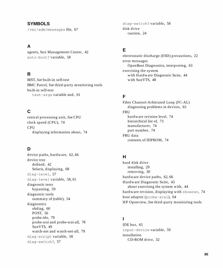
SYMBOLS/var/adm/messages file, 67
Aagents, Sun Management Center, 42auto-boot? variable, 58
BBIST, See built-in self-testBMC Patrol, See third-party monitoring toolsbuilt-in self-test
test-args variable and, 61
Ccentral processing unit, See CPUclock speed (CPU), 74CPU
displaying information about, 74
Ddevice paths, hardware, 62, 66device tree
defined, 42Solaris, displaying, 68
diag-level, 57diag-level variable, 58, 61diagnostic tests
bypassing, 59diagnostic tools
summary of (table), 54diagnostics
obdiag, 60POST, 56probe-ide, 79probe-scsi and probe-scsi-all, 78SunVTS, 49watch-net and watch-net-all, 79
diag-script variable, 58diag-switch?, 57
diag-switch? variable, 58disk drive
caution, 24
Eelectrostatic discharge (ESD) precautions, 22error messages
OpenBoot Diagnostics, interpreting, 63exercising the system
with Hardware Diagnostic Suite, 44with SunVTS, 48
FFibre Channel-Arbitrated Loop (FC-AL)
diagnosing problems in devices, 63FRU
hardware revision level, 74hierarchical list of, 73manufacturer, 74part number, 74
FRU datacontents of IDPROM, 74
Hhard disk drive
installing, 29removing, 30
hardware device paths, 62, 66Hardware Diagnostic Suite, 43
about exercising the system with, 44hardware revision, displaying with showrev, 74host adapter (probe-scsi), 64HP Openview, See third-party monitoring tools
IIDE bus, 65input-device variable, 59installation
CD-ROM drive, 32
85
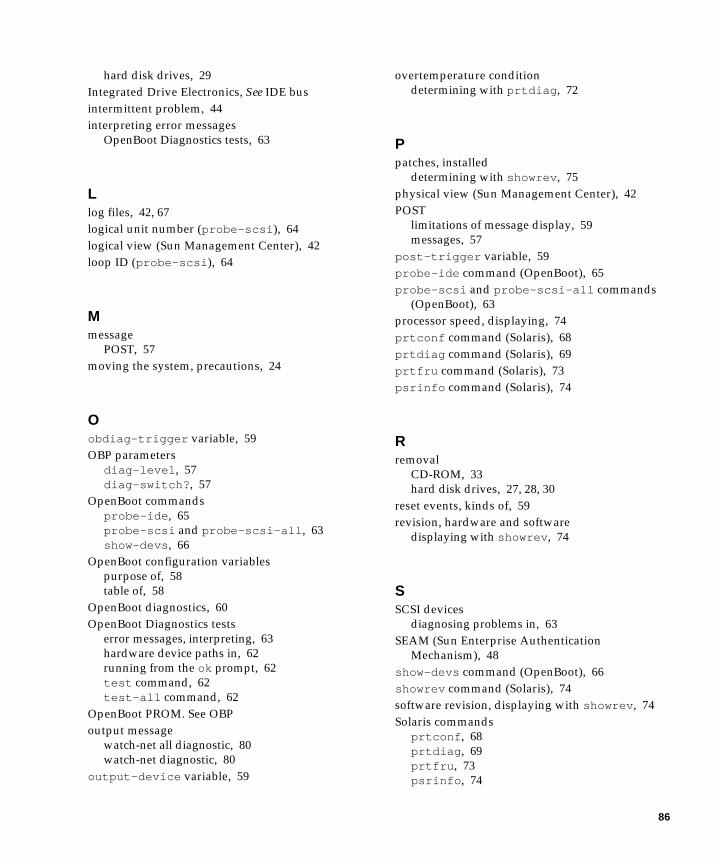
hard disk drives, 29Integrated Drive Electronics, See IDE busintermittent problem, 44interpreting error messages
OpenBoot Diagnostics tests, 63
Llog files, 42, 67logical unit number (probe-scsi), 64logical view (Sun Management Center), 42loop ID (probe-scsi), 64
Mmessage
POST, 57moving the system, precautions, 24
Oobdiag-trigger variable, 59OBP parameters
diag-level, 57diag-switch?, 57
OpenBoot commandsprobe-ide, 65probe-scsi and probe-scsi-all, 63show-devs, 66
OpenBoot configuration variablespurpose of, 58table of, 58
OpenBoot diagnostics, 60OpenBoot Diagnostics tests
error messages, interpreting, 63hardware device paths in, 62running from the ok prompt, 62test command, 62test-all command, 62
OpenBoot PROM. See OBPoutput message
watch-net all diagnostic, 80watch-net diagnostic, 80
output-device variable, 59
overtemperature conditiondetermining with prtdiag, 72
Ppatches, installed
determining with showrev, 75physical view (Sun Management Center), 42POST
limitations of message display, 59messages, 57
post-trigger variable, 59probe-ide command (OpenBoot), 65probe-scsi and probe-scsi-all commands
(OpenBoot), 63processor speed, displaying, 74prtconf command (Solaris), 68prtdiag command (Solaris), 69prtfru command (Solaris), 73psrinfo command (Solaris), 74
Rremoval
CD-ROM, 33hard disk drives, 27, 28, 30
reset events, kinds of, 59revision, hardware and software
displaying with showrev, 74
SSCSI devices
diagnosing problems in, 63SEAM (Sun Enterprise Authentication
Mechanism), 48show-devs command (OpenBoot), 66showrev command (Solaris), 74software revision, displaying with showrev, 74Solaris commands
prtconf, 68prtdiag, 69prtfru, 73psrinfo, 74
86
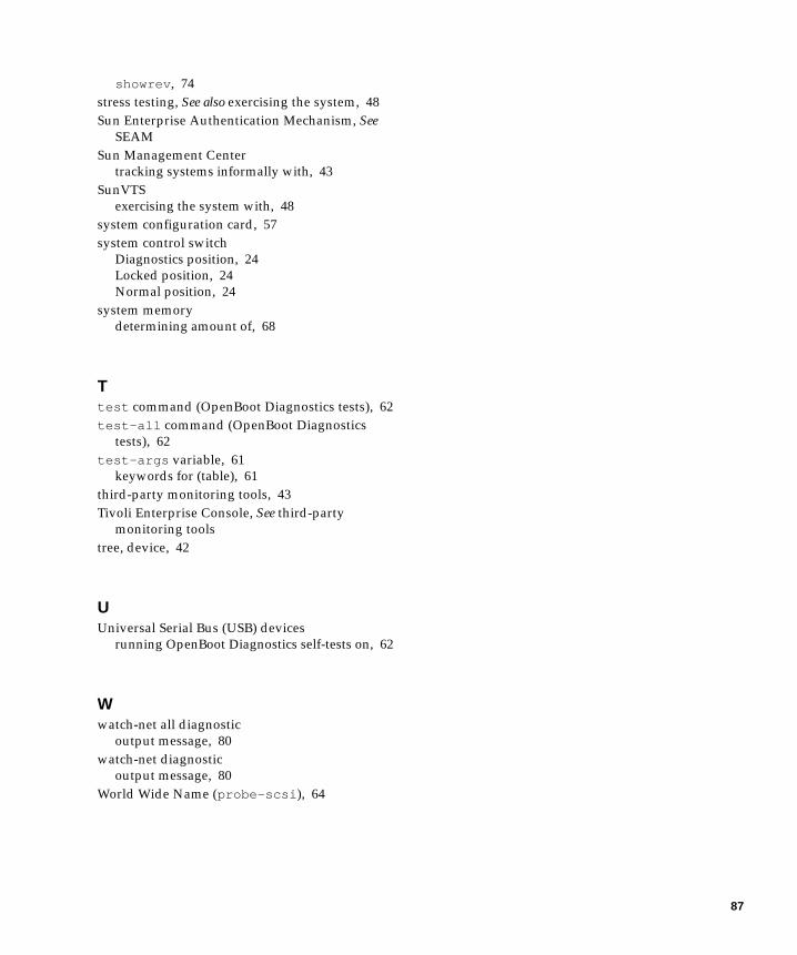
showrev, 74stress testing, See also exercising the system, 48Sun Enterprise Authentication Mechanism, See
SEAMSun Management Center
tracking systems informally with, 43SunVTS
exercising the system with, 48system configuration card, 57system control switch
Diagnostics position, 24Locked position, 24Normal position, 24
system memorydetermining amount of, 68
Ttest command (OpenBoot Diagnostics tests), 62test-all command (OpenBoot Diagnostics
tests), 62test-args variable, 61
keywords for (table), 61third-party monitoring tools, 43Tivoli Enterprise Console, See third-party
monitoring toolstree, device, 42
UUniversal Serial Bus (USB) devices
running OpenBoot Diagnostics self-tests on, 62
Wwatch-net all diagnostic
output message, 80watch-net diagnostic
output message, 80World Wide Name (probe-scsi), 64
87

88 Sun Fire V210 and V240 Servers Administration Guide • April 2003